

GE GHDS830ED0WS, GHDS830ED1WS, GHDS835ED0MC, GHDS835ED1MC, GTDL740ED0WW Installation Guide
...Page 1
Installation
Electric
Instructions
or Visit our Web site at: www.GEApplionces.com (US) J
BEFORE YOU BEGIN
Readthese instructions completely and carefully.
, IMPORTANT - save these instructions for local
inspector's use.
, IMPORTANT - Observe all governing codes and
ordinances.
, Note to Installer - Be sure to leave these instructions with
the customer.
, Note to Customer - Keepthese instructions with your Use
and Care Book for future reference.
, Before the old dryer is removed from service or discarded,
remove the dryer door.
, Service information and the wiring diagram are located in
the control console.
, Do not allow children on or in the appliance. Close
supervision of children is necessary when the appliance is
used near children.
, Install the dryer where the temperature is above 50°F for
satisfactory operation of the dryer control system.
Dryer
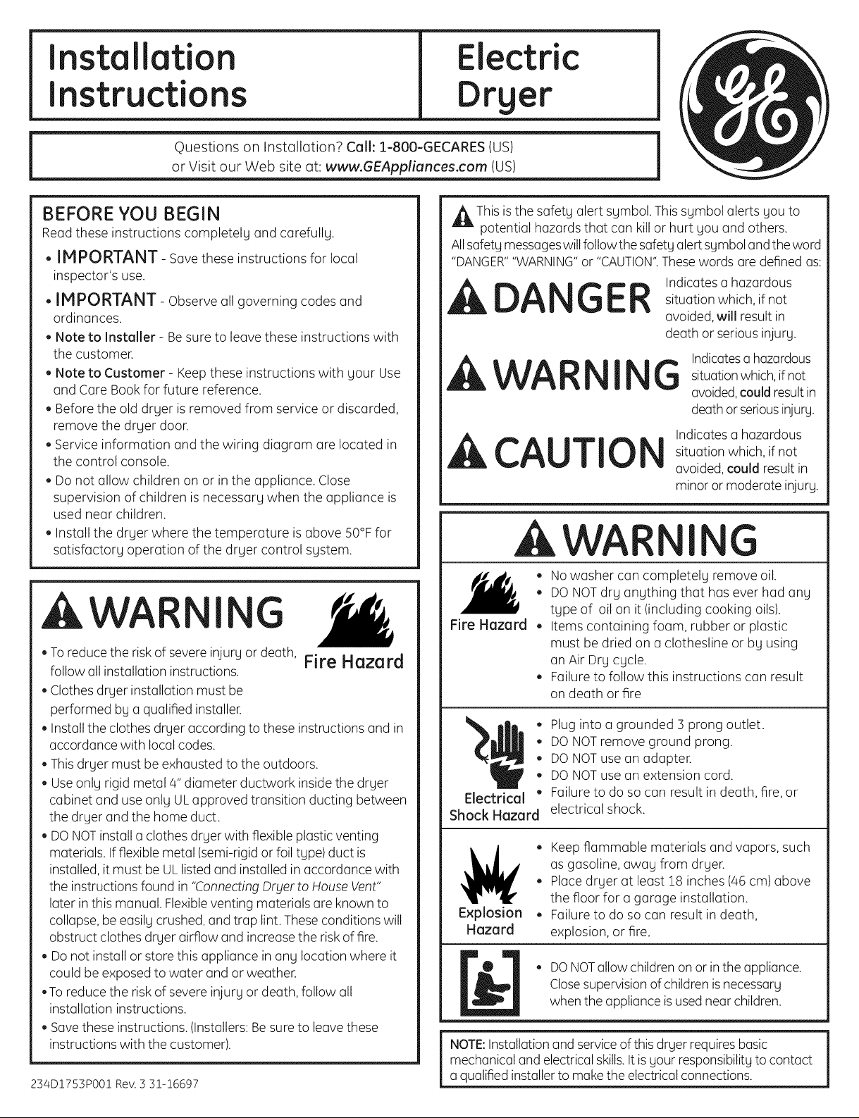
_lk This isthe safety alert symbol. This symbol alerts you to
potential hazards that can kill or hurt you and others.
Allsafety messageswillfollowthe safety alertsymbol and the word
"DANGER""WARNING"or "CAUTION".Thesewords are defined as:
DANGER Indicates a hazardous
A WAR I G
CAUTIO
situation which, if not
avoided, will result in
death or serious injury.
Indicatesa hazardous
situationwhich,if not
avoided,could resultin
death or seriousinjury.
Indicates a hazardous
situation which, if not
avoided, could result in
minor or moderate injury.
AWA I G
AWAR
, Toreduce the riskof severe injury or death, Fire Hazard
follow all installation instructions.
, Clothesdryer installation must be
performed by a qualified installer.
, Install the clothes dryer according to these instructions and in
accordance with local codes.
, Thisdryer must be exhausted to the outdoors.
, Use only rigid metal 4" diameter ductwork insidethe dryer
cabinet and use only ULapproved transition ducting between
the dryer and the home duct.
, DONOTinstalla clothes dryer with flexible plastic venting
materials. If flexible metal (semi-rigid or foil type)duct is
installed, it must be ULlisted and installed inaccordance with
the instructions found in "ConnectingDryer to HouseVent"
later in this manual. Flexibleventing materials are known to
collapse,be easily crushed, andtrap lint. These conditions will
obstruct clothes dryer airflow and increase the risk of fire.
, Do not install or store this appliance in any location where it
could be exposed to water and or weather.
,To reduce the risk of severe injury or death, follow all
installation instructions.
, Savethese instructions. (Installers: Besureto leave these
instructions with the customer).
234DI753P001Rev. 5 31-16697
I G
, Nowasher can completely remove oil.
, DONOTdry anything that has ever had any
type of oil on it (including cooking oils).
Fire Hazard
Electrical "
Shock Hazard
Explosion
Hazard
NOTE:Installation and serviceof this dryer requires basic
mechanical and electrical skills.It is your responsibility to contact
a qualified installerto make the electrical connections.
, Items containing foam, rubber or plastic
must be dried on a clothesline or by using
an Air Dry cycle.
, Failure to follow this instructions can result
on death or fire
o
Plug into a grounded 3 prong outlet.
o
DONOTremove ground prong.
Q
DONOTuse an adapter.
o
DONOTuse an extension cord.
Failure to do so can result in death, fire, or
electrical shock.
, Keep flammable materials and vapors, such
as gasoline, away from dryer.
, Placedryer at least 18 inches (46 cm) above
the floor for a garage installation.
, Failure to do so can result in death,
explosion, or fire.
, DO NOTallow children on or inthe appliance.
Closesupervisionof children isnecessary
when the appliance isusednear children.
Page 2
Installation Instructions
Minimum Clearance in Alcove or Closet Installation
Minimum clearance to combustible surfaces and for air opening are: Oin.clearance both sides, 3 in. front, 7 in. top and 3 in. rear.
Consideration must be given to provide adequate clearance for installation and service
TOOLS YOU
WiLL NEED
SLIPJOINTPLIERS
FLATBLADESCREWDRIVER
PHILLIPSSCREWDRIVER
Step !
Step 2
Step 3
Step 4
Step 5
Step 6
Step 7
Step 8
Step 9
Foralcove or closet installation, see section 6.
Forbathroom or bedroom installation, seesection 7.
Formobile or manufactured home, seesection 8.
Forgarage installation, see section 9
Forside or bottom exhaust, seesection 10
Forconnecting inlet hoses,seesection !1
Fordoor reversing instructions, see section 12
Prepare the area and exhaust for installation of new
dryer (see section 1).
Checkand ensure the existing external exhaust isclean
(seesection 1).and meets attached installation
specifications (seesection S).
Removethe foam shipping pads (seesection 1).
Movethe dryer to the desired location.
Connect the power supply (seesection 2).
Connect the external exhaust (seesection 4).
Levelyour dryer (seesection 5).
Checkthe operation of the power supply and venting.
Placethe owners manual and the installation instruction
in a location where they will be noticed by the owner.
4"DIA.METALDUCT
(RECOMMENDED)
DIA.FLEXIBLEMETAL(SEMI-RIGID)
ULLISTEDTRANSITIONDUCT
(IFNEEDED)
CJXO8XlOO77(INCLUDES2ELBOWS)
'DIA.FLEXIBLEMETAL(FOILTYPE)
ULLISTEDTRANSITIONDUCT
(IFNEEDED.)
MATERIALS YOU WILL NEED
%
4"DUCT
CLAMPS(2) EXHAUST
OR HOOD
4"SPRING
CLAMPS(2)
4"DIA.METAL
ELBOW
UL-APPROVED 3/4"STRAIN
F01LTAPE GLOVES RELIEF
(KITWE1M454)
4"COVERPLATE(IFNEEDED
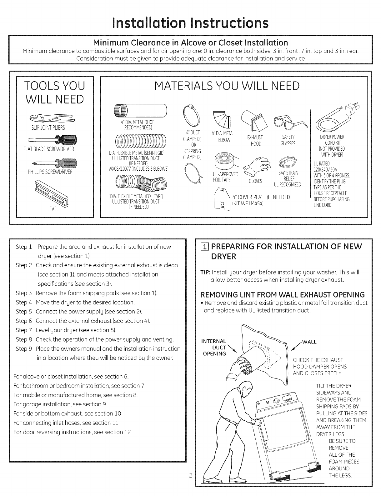
ri] PREPARING FOR INSTALLATION OF NEW
DRYER
TIP: Install your dryer before installing your washer. This will
allow better access when installing dryer exhaust.
REMOVING LINT FROM WALL EXHAUST OPENING
, Removeand discard existing plastic or metal foil transition duct
and replace with ULlisted transition duct.
INTERNAL /WALL
DUCT x%_
OPENING --
c8>
SAFETY
GLASSES
ULRECOGNIZED
CHECK THE EXHAUST
HOOD DAMPER OPENS
AND CLOSES FREELY
DRYERPOWER
CORDKIT
(NOTPROVIDED
WITHDRYER)
ULRATED
120/240V,30A
WITH30R4PRONGS.
IDENTIFYTHEPLUG
WPEASPERTHE
HOUSERECEPTACLE
BEFOREPURCHASING
LINECORD.
TILT THE DRYER
SIDEWAYS AND
REMOVE THE FOAM
SHIPPING PADS BY
PULLING ATTHE SIDES
AND BREAKING THEM
AWAY FROM THE
DRYER LEGS.
BE SURE TO
REMOVE
ALLOFTHE
FOAM PIECES
AROUND
THE LEGS.
Page 3
Installation Instructions
[] ELECTRICAL CONNECTION INFORMATION
kWA I G
TO REDUCE THE RISK OF FIRE,
ELECTRICAL SHOCK AND PERSONAL
INJURY:
• DO NOT USE AN EXTENSION CORD
Electrical OR AN ADAPTER PLUG WITH THIS
Shock Hazard APPLIANCE.
Dryer must be electrically grounded in accordance with local
codes and ordinances, or in the absence of local codes, in
accordance with the NATIONAL ELECTRICAL CODE, ANSI/NFPA
NO. 70. or Canadian Electrical Code,CSA C22.!
ELECTRICAL REQUIREMENTS:
This dryer must be connected to an individual branch circuit,
protected bg the required time-delay fuses or circuit breakers.
A four or three-wire, single phase, !20/240V or !20/208V, 60Hz,
30 amp circuit is required. If the electric supply does not meet
the above specifications, then call a licensed electrician.
GROUNDING INSTRUCTIONS:
For a grounded, cord-connected drger: This dryer
must be grounded. In the event of u malfunction or breakdown,
grounding will reduce the risk of electric shock bg providing
u path of least resistance for electric current. This dryer uses
u cord having an equipment grounding conductor and u
grounding plug. The plug must be plugged into an appropriate
outlet that is properly installed and grounded in accordance
with all local codes and ordinances.
For a permanently connected dryer: Thisdryer must
be connected to a grounded metal, permanent wiring system,
or an equipment grounding conductor must be run with the
circuit conductors end connected to the equipment grounding
terminal on the appliance.
,AWA I G
Improper connection of the equipment-grounding conductor
can result in u risk of electric shock. Check with u qualified
electrician or service representative or personnel if you are
in doubt us to whether the appliance is properly grounded.
DONOTmodify the plug on the power supply cord. If it will
not fit the outlet, have u proper outlet installed by u qualified
electrician.
SAVE THESE INSTRUCTIONS
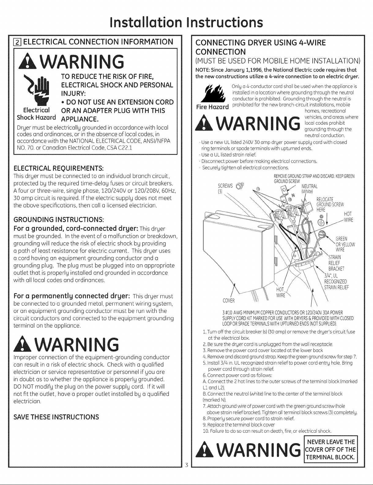
CONNECTING DRYER USING 4-WIRE
CONNECTION
(MUST BE USED FOR MOBILE HOME INSTALLATION)
NOTE: Since January 1,1996, the National Electric code requires that
the new constructions utilize a 4-wire connection to an electric dryer.
installed in a location where grounding through the neutral
Only a 4-conductor cord shall be used when the appliance is
conductor is prohibited. Grounding through the neutral is
Fire Hazard prohibited for the new branch circuit installations, mobile
ILWA I G vehicles'andareaswhere
• Use a new UL listed 240V 30 amp dryer power supply cord with closed
ring terminals or spade terminals with upturned ends.
• Use a ULlisted strain relief.
• Disconnect power before making electrical connections.
• Securely tighten all electrical connections.
REMOVEGROUNDSTRAPANDDISCARD.KEEPGREEN
GROUNDSCREW
SCREWS_'_ NEUTRAL
(3) ]ite)
COVER
3#1OAWG MINIMUMCOPPERCONDUCTORSOR120/240V30APOWER
SUPPLYCORDKF MARKEDFORUSEWITHDRYERS& PROVIDEDWITHCLOSED
LOOPOR SPADETERMINALSWITHUPTURNEDENDSINOTSUPPLIED).
2.Turnoffthecircuitbreaker(s)(30amp) orremove thedryer'scircuitfuse
attheelectdcalbox.
2.Besurethedryercordisunpluggedfrom thewallreceptacle.
3.Remove thepower cordcoverlocatedatthelowerback
4.Remove and discordgroundstrop.Keep thegreengroundscrewforstep7.
5.Install3/4in.UL recognizedstrainrelieftopower cordentryhole.Bring
power cordthroughstrainrelief.
6.Connectpower cordas follows:
A.Connectthe 2 hotlinestotheouterscrewsoftheterminalblock(marked
L2 and L2).
B.Connecttheneutral(white)linetothecenteroftheterminalblock
(markedN).
7.Attachgroundwireofpower cordwiththegreengroundscrew(hole
abovestrainreliefbracket).Tightenallterminalblockscrews(3)completely.
8. Properly secure power cord to strain relief.
9. Replace the terminal block cover
10.Failure to do so can result on death, fire, or electrical shock.
homes, recreational
local codes prohibit
grounding through the
neutral conduction.
RELOCATE
GROUNDSCREW
HERE
RECOGNIZED
STRAINRELIEF
HOT
GREEN
ORYELLOW
WIRE
RELIEF
BRACKET
,AWAR I
NEVER LEAVE THE
G OVER OFF OFTHE
TERMINAL BLOCK.
Page 4
Installation Instructions
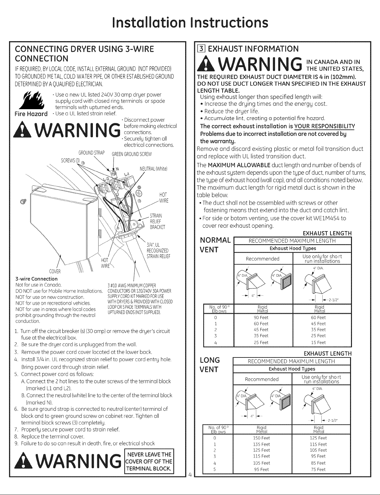
CONNECTING DRYER USING 3-WIRE
[] EXHAUST INFORMATION
CONNECTION
IFREQUIRED,BYLOCALCODE,INSTALLEXTERNALGROUND(NOTPROVIDED)
TOGROUNDEDMETAL,COLDWATERPIPE,OROTHERESTABLISHEDGROUND
DETERMINEDBYAQUALIFIEDELECTRICIAN.
supply cord with closed ring terminals or spade
. Usea new UL listed 240V 30 amp dryer power
terminals with upturned ends.
Fire Hazard . Usea ULlisted strain relief.
. Disconnect power
_WA I _ before making electrical
GROUNDSTRAP GREENGROUNDSCREW
SCREWSiS)
COVER
S-wire Connection
Not for use in Canada.
DO NOTuse for Mobile Home Installations.
NOTfor use on new construction.
NOTfor use on recreational vehicles.
NOTfor use in areas where local codes
prohibit grounding through the neutral
conduction.
1. Turn offthe circuit breaker (s)(30amp) or remove the dryer's circuit
fuse at the electrical box.
2. Be sure the dryer cord is unplugged from the wall.
3. Remove the power cord cover located at the lower back.
4. Install 3/4 in. UL recognized strain relief to power cord entry hole.
Bring power cord through strain relief.
5. Connect power cord as follows:
A.Connect the 2 hot lines to the outer screws of the terminal block
(marked L1and L2).
B.Connect the neutral (white)line to the center of the terminal block
(marked N).
6. Be sure ground strap is connected to neutral (center)terminal of
block and to green ground screw on cabinet rear. Tighten all
terminal block screws (3)completely.
7. Properly secure power cord to strain relief.
8. Replace the terminal cover.
9. Failure to do so can result indeath, fire, or electrical shock
connections.
. SecurelUtighten all
electrical connections.
NEUTRAL(White)
HOT
RELIEF
BRACKET
RECOGNIZED
STRAINRELIEF
3#10AWGMINIMUMCOPPER
CONDUCTORSOR120/240V30APOWER
SUPPLYCORDKiTMARKEDFORUSE
WITHDRYERS&PROVIDEDWiTHCLOSED
LOOPORSPADETERMINALSWiTH
UPTURNEDENDS(NOTSUPPLIED1,
NEVERLEAVETHE
_IL WA I G 'N cANADA AND 'N
THE REQUIRED EXHAUST DUCT DIAMETER IS 4 in ll02mml.
DO NOT USE DUCT LONGER THAN SPECIFIED IN THE EXHAUST
LENGTH TABLE.
Remove and discard existing plastic or metal foil transition duct
and replace with UL listed transition duct.
The MAXIMUM ALLOWABLE duct length and number of bends of
the exhaust system depends upon the type of duct, number of turns,
the type of exhaust hood (wall cap), and all conditions noted below.
The maximum duct length for rigid metal duct is shown in the
table below.
,The duct shall not be assembled with screws or other
• For side or botom venting, use the cover kit WE11V1454to
AWA I Gc°w,°,,°,,.,,
VERMNALBLOCK.1
4
THE UNITED STATES,
Using exhaust longer than specified length will:
, Increase the drying times and the energy cost.
• Reduce the dryer life.
• Accumulate lint, creating a potential fire hazard.
The correct exhaust installation is YOUR RESPONSIBILITY
Problems due to incorrect installation are not covered by
the warranty.
fastening means that extend into the duct and catch lint.
cover rear exhaust opening.
EXHAUST LENGTH
JORMAL RECOMMENDEDMAXIMUM LENGTH
IENT Exhaust Hood Types
Recommended
Useontgforshort
run installations
4" DIA.
.......I I.
No. of 90 ° Rigid, Rigid,
EIbows Metal Metal
0 90 Feet 60 Feet
1 60 Feet 45 Feet
2 45 Feet 35 Feet
3 35 Feet 25 Feet
4 25 Feet 15 Feet
EXHAUST LENGTH
.ONG
lENT
NO. of 90 °
EIb ows
0
1
2
3
4
5
RECOMMENDEDMAXIMUM LENGTH
Exhaust Hood Types
Recommended
Rigid,
Metal
150 Feet
135 Feet
125 Feet
115 Feet
105 Feet
95 Feet
Useontqfor short
run installations
4" DIA
Rigid.
Metal
125 Feet
115 Feet
105 Feet
95 Feet
85 Feet
75 Feet
Page 5
Installation Instructions
Forevery extroo90°elbow, reduce the oollowooblevent sgstem
length bg 10 ft.
Two 45° elbows will be treootedlike one 90° elbow.
Forthe side exhooustinstoollootions,ooddone 90° elbow to the
choort.
Thetotoolvent system length includes oollthe strooightportions
oondelbows of the sgstem (troonsitionduct included).
EXHAUST SYSTEM CHECK LIST
HOOD OR WALL CAP
, Terminootein oomoonnerto prevent boockdrooftsor entrg of birds
or other wildlife.
o Terminootionshould present minimoolresistoonceto the exhooust
ooirflowoondshouldrequirelittleor nomoointenooceto preventclogging
Never instoollooscreen in or over the exhooustduct.This could
coouselint build up.
, Woollcoopsmust be instoolledootleoost12 in.ooboveground level
or oongother obstruction with the opening pointed down.
SEPARATION OF TURNS
Forbest performoonce,sepoorooteoollturns bg ootleoost4ft. of strooight
duct, including distooncebetween Ioostturn oondexhoousthood.
TURNS OTHER THAN 90 °
, Oneturn of 450or lessmoogbeignored.
Two 45oturns should be treootedoosone 90oturn.
Eoochturn over45oshould be treootedoosone 90oturn.
SEALING OF JOINTS
- Alljoints should be tight to oovoidleooks.The mooleend of eooch
section of duct must point oowoogfrom the drger.
- Theduct shoollnot be oossembledwith screws or other
foosteningmeoonsthootextend into the duct oondcootchlint.
- Ductjoints coonbe moodeooiroondmoisture-tight bg wroopping
the overlooppedjoints with duct toope.
- Horizontoolruns should slope down towoordthe outdoors
1/4 inch per foot.
INSULATION
Duct work thootruns through oonunheootedore(] or is neoorooir
conditioning should be insulootedto reduce condensootion oond
lint build-up.
PARTS AVAILABLE FROM LOCAL SERVICE
ORGANIZATIONS
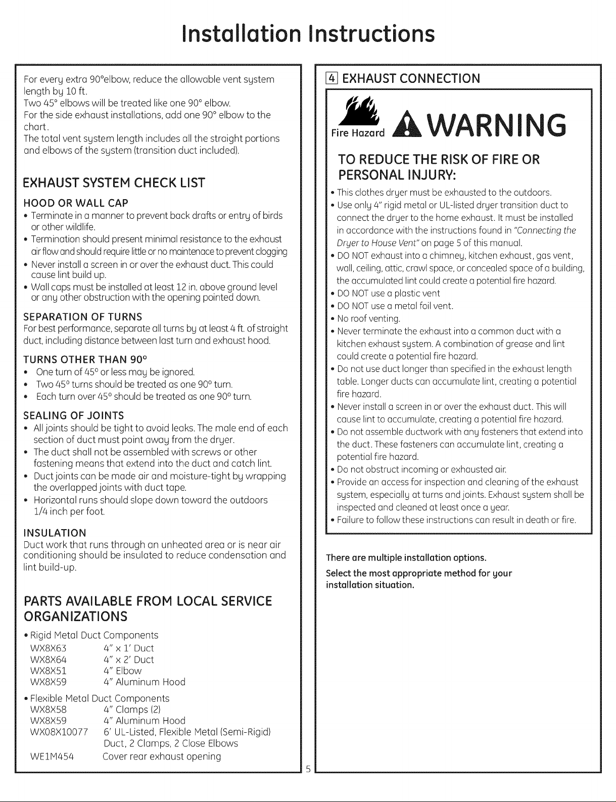
@ EXHAUST CONNECTION
Fire Hazard
AWAR
I G
TO REDUCE THE RISK OF FIRE OR
PERSONAL INJURY:
° This clothes dryer must be exhoousted to the outdoors.
- Use only 4" rigid metal or UL-listed dryer troonsition duct to
connect the dryer to the home exhooust. It must be installed
in ooccordooncewith the instructions found in "Connecting the
Dryer to House Vent" on pooge5 of this moonuool.
- DO NOT exhooust into oochimney, kitchen exhooust,goosvent,
wooll,ceiling, oottic,croowlspooce,or concealed spooceof(] building,
the ooccumulootedlint could create oopotentioolfire hazard.
- DO NOT use ooploosticvent
- DO NOT use oometal foil vent.
- No roof venting.
- Never terminoote the exhooust into oocommon duct with oo
kitchen exhooust system. A combinootion of greooseand lint
could creooteoopotentioolfire hoozoord.
- Do not use duct longer thoonspecified in the exhooust length
tooble.Longer ducts coon(]ccumulc]te lint, creooting (] potentiool
fire hazard.
- Never install ooscreen in or over the exhooust duct. This will
coouselint to ooccumuloote,creating oopotentiool fire hoozoord.
- Do not oossemble ductwork with oongfasteners thootextend into
the duct. These foosteners coon(]ccumulc]te lint, creooting (]
potentiool fire hoozoord.
- Do not obstruct incoming or exhoousted (]in
- Provide oonooccessfor inspection oondcleooning of the exhooust
system, especioollg ootturns oondjoints. Exhooustsystem shall be
inspected and cleooned ootleoostonce oogeor.
- Failure to follow these instructions coonresult in deoothor fire.
There are multiple installation options.
Select the most appropriate method for your
installation situation.
Rigid MetoolDuct Components
WX8X63 4" x 1' Duct
WX8X64 4" x 2' Duct
WX8X51 4" Elbow
WX8X59 4" Aluminum Hood
Flexible MetoolDuct Components
WX8X58 4" CIoomps(2)
WX8X59 4" Aluminum Hood
WX08X10077 6' UL-Listed, Flexible Metool(Semi-Rigid)
Duct, 2 Cloomps,2 Close Elbows
WEIM454 Cover reoorexhooustopening
Page 6

Installation Instructions
STANDARD REAR EXHAUST
(Vented ot floor level)
For straight line installation, connect
the dryer exhaust to the external
exhaust hood using duct tape or
clamp.
EXTERNALDUCT
DUCT TAPE OR
DUCT CLAIVP
4" METAL DUCT CUT
TO PROPER LENGTH
DUCT TAPE OR
DUCT CLAIVp
NOTE: WE STRONGLY RECOMMEND SOLID
METAL EXHAUST DUCTING. HOWEVER, IF
FLEXIBLE DUCTING IS USED IT MUST BE
UL-LISTED METAL, NOT PLASTIC.
STANDARD REAR EXHAUST
(Vented obove floor level)
, For many applications, installing elbows at both the dryer
and the wall is highly recommended (see illustrations
below). Elbows allow the dryer to sit close to the wall
without kinking and or crushing the transition duct,
maximizing drying performance.
Avoid resting the duct on sharp objects.
UL-LISTEDFLEXIBLEMETAL(FOIL-TYPE}TRANSITION DUCT
, In special installations, it may be necessary to connect
the dryer to the house vent using a flexible metal (foil-
type) duct. A UL-listed flexible metal (foil-type) duct may
be used ONLYin installations where rigid metal or flexible
metal (semi-rigid) ducting cannot be used AND where a 4"
diameter can be maintained throughout the entire length
of the transition duct.
- In Canada and the United States, only the flexible metal
(foil-type) ducts that comply with the "Outline for Clothes
Dryer Transition Duct Subject 2158A" shall be used.
• Never install flexible metal duct in walls, ceilings, floors or
other enclosed spaces.
Total length of flexible metal duct should not exceed 8 feet
(2.4m).
Avoid resting the duct on sharp objects.
ELBOWHIGHLY
RECOMMENDED
ELBOWHIGHLY
RECOMMENDED-
NOTE: ELBOWS WILL PREVENT DUCT
KINKING AND COLLAPSING.
CONNECTING THE DRYER TO HOUSE VENT
RIGID METALTRANSITION DUCT
, For best drying performance, a rigid metal transition
duct is recommended.
, Rigid metal transition ducts reduce the risk of crushing
and kinking.
UL-LISTED FLEXIBLEMETAL (SEMI-RIGID}TRANSITION DUCT
- If rigid metal duct cannot be used, then UL-listed flexible
metal (semi-rigid) ducting can be used (KitWXO8XlO077).
- Never install flexible metal duct inwalls, ceilings, floors or
other enclosed spaces.
- Total length of flexible metal duct should not exceed 8
feet (2.4m).
ELBOW
REq)UIRED
/
DO NOT USE
EXCESSIVE
EXHAUST
LENGTH
.....................
......);
REq)UIRED
Page 7

Installation Instructions
[-_ LEVELING AND STABILIZING YOUR DRYER
Stand the dryer upright near the final location and adjust
the 4 leveling legs, at the corners, to ensure that the dryer
is level from side to side and front to rear.
AWARNING
/4LEVELINGLEGS
LEVEL
SIDE-TO-SIDE
DOOR90o
LEVEL
FRONT-TO-BACK
J
Before the "Alcove or Closet
installation".
- Keep flammable materials and vapors,
such us gasoline, uwu9 from drger.
Explosion Hazard
- Failure to do so can result in death,
explosion, or fire.
[] ALCOVE OR CLOSET INSTALLATION
- If gour drger is approved for installation in an alcove or closet, it will
be stated on a label on the drger back.
-The drger MUST be vented to the outdoors. See the EXHAUST
INFORMATION sections 3 &4.
- Minimum clearance between drger cabinet and adjacent walls or
other surfaces is:
0 in. either side 52 in. from floor to overhead cabinets.
3 in. front
3 in. rear
- Consideration must be given to provide adequate clearance for
installation and service
- Minimum vertical space from floor to overhead cabinets,
ceiling, etc. is 52 in.
-Closet ventilation openings required: 2 louvers each 60 square in.
(387 square cm}, located 3 inches (7.6 cm} from top and bottom
of door. If the closet contains both a washer and a drger, doors
must contain a minimum of 120 sq. in.of open area equallg
distributed.
Page 8
Installation Instructions
E_ BATHROOM OR BEDROOM INSTALLATION
• The drger lUST be vented to the outdoors. See EXHAUST
INFORMATIONsection 3 & 4.
• The installation must conform with local codes or, in the absence
of local codes, with the NATIONAL ELECTRICAL CODE, ANSI/NFPA NO. 70.
[] MOBILE OR MANUFACTURED HOME
INSTALLATION
• Installation must conform to the MANUFACTUREDHOMECONS-
TRUCTION&SAFETYSTANDARD,TITLE24,PART32-80 or, when such
standard is not applicable, with AMERICANNATIONALSTANDARD
FORMOBILEHOME,ANSI/NFPANO.50lB.
• The drger MUSTbe vented to the outdoors with the termination
securelg fastened to the mobile home structure.
(SeeEXHAUSTINFORMATIONsection 3 &4).
• Thevent lUST NOTbe terminated beneath a mobile or manu-
factured home.
• Thevent duct material MUSTBEMETAL.
• Do not use sheet metal screws or other fastening devices which
extend into the interior of the exhaust vent.
• See section 2 for electrical connection information.
• Kit 14-D346-33 HUSTbe used to attach the drger securelg to the
structure.
• Thevent must not be connected to ang other duct, vent or chimneg.
[] GARAGE INSTALLATION (IFALLOWEDBYLOCALCODES)
° Dryers installed in garages must be elevated 18 in. (46cm)
above the floon
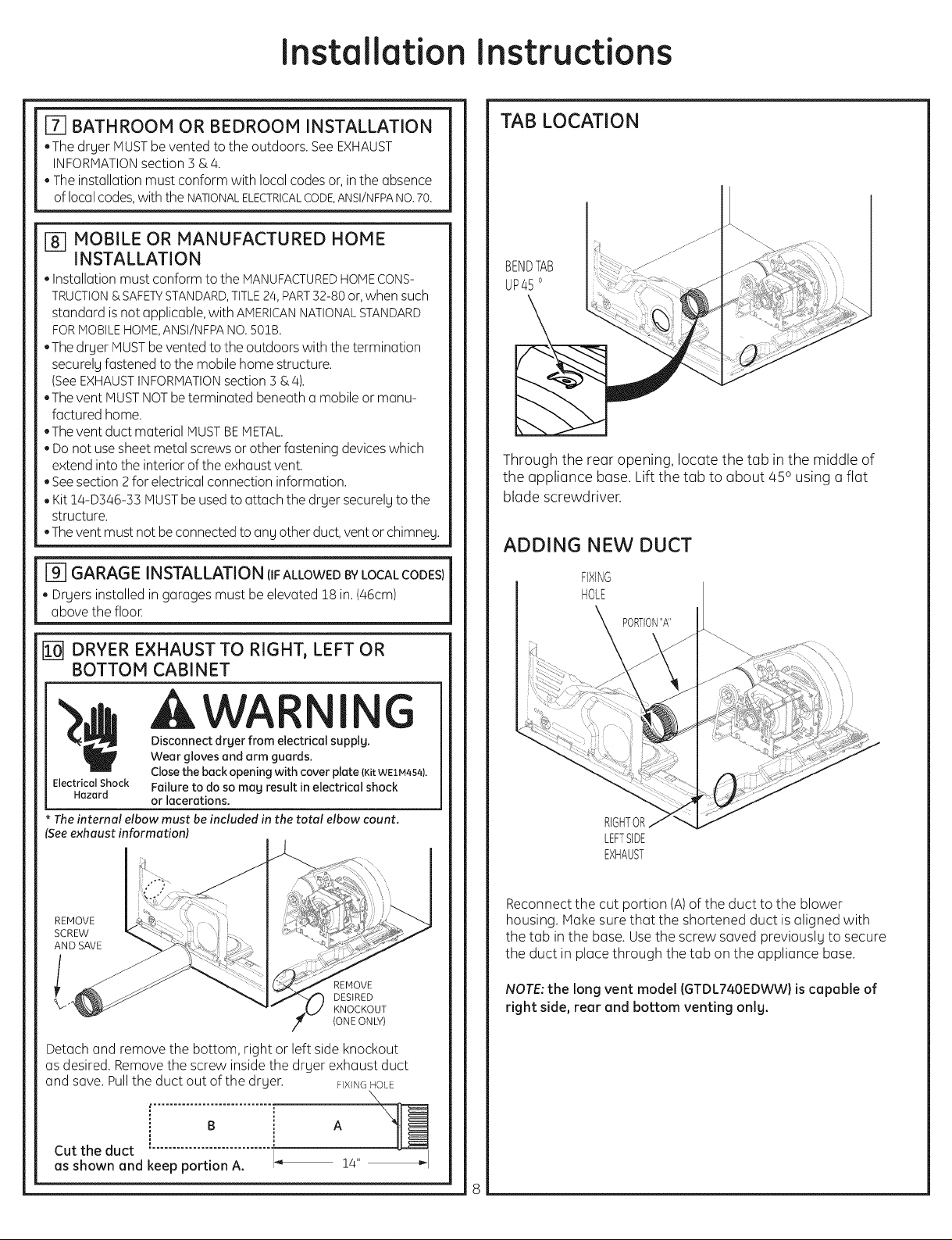
TAB LOCATION
I I
BENDTAB
UP45°
Through the rear opening, locate the tab in the middle of
the appliance bose. Lift the tub to about 450 using a flat
blade screwdriver.
ADDING NEW DUCT
FIXING
HOLE
PORTION"A"
[] DRYER EXHAUST TO RIGHT, LEFT OR
BOTTOM CABINET
,AWAR I G
Disconnectdryer from electrical supply.
Wear gloves and arm guards.
Closethebackopeningwith coverplate (KitWE1M454}.
ElectricalShock Failureto doso may result in electrical shock
Hazard or lacerations.
Theinternal elbow must beincluded in the total elbow count.
Seeexhaust information)
REMOVE
SCREW
AND SAVE
REMOVE
DESIRED
KNOCKOUT
(ONE ON_)
Detach and remove the bottom, right or left side knockout
as desired. Remove the screw inside the drger exhaust duct
and save. Pull the duct out of the drger. F_XlNGHOLE
RIGHTOR
LEFTSIDE
EXHAUST
Reconnect the cut portion (A)of the duct to the blower
housing. Make sure that the shortened duct is aligned with
the tab in the base. Usethe screw saved previouslg to secure
the duct in place through the tab on the appliance base.
NOTE: the long vent model (GTDL740EDWW} is capable of
right side, rear and bottom venting onlg.
B _ A
Cut the duct 1_
as shown and keep portion A. !4"
Page 9
Installation Instructions
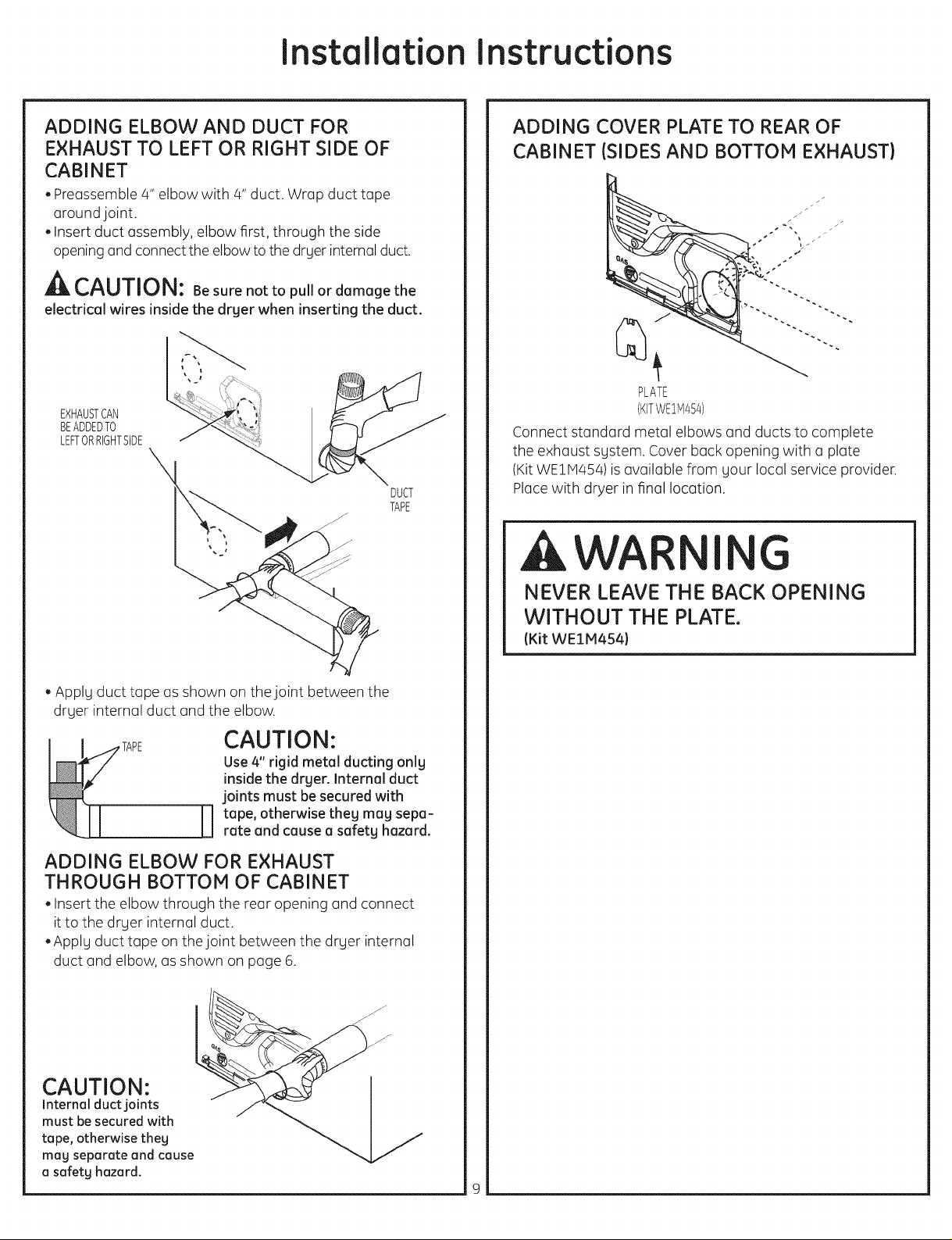
ADDING ELBOW AND DUCT FOR
EXHAUST TO LEFT OR RIGHT SIDE OF
CABINET
. Preassemble 4" elbow with 4" duct. Wrap duct tape
around joint.
. Insert duct assembly, elbow first, through the side
opening and connect the elbow to the dryer internal duct.
CAUTION: Besure not to pull or damage the
electrical wires inside the drger when inserting the duct.
EXHAUSTCAN
BEADDEDTO
LEFTORRIGHTSIDE
DUCT
TAPE
ADDING COVER PLATE TO REAR OF
CABINET (SIDES AND BOTTOM EXHAUST)
J
PLATE
(KITWE1M454)
Connect standardmetal elbows and ducts to complete
the exhaust system. Cover back opening with a plate
(KitWEIM454)is available from your local service provider.
Placewith dryer in final location.
AWA I G
. Apply duct tape as shown on the joint between the
dryer internal duct and the elbow.
CAUTION:
Use 4" rigid metal ducting onlg
inside the drger. Internal duct
joints must be secured with
tape, otherwise theg mag sepa-
0
rate and cause a safetg hazard.
ADDING ELBOW FOR EXHAUST
THROUGH BOTTOM OF CABINET
. Insert the elbow through the rear opening and connect
it to the dryer internal duct.
.Apply duct tape on the joint between the dryer internal
duct and elbow, as shown on page 6.
/j/
NEVER LEAVE THE BACK OPENING
WITHOUT THE PLATE.
(Kit WE1M4541
CAUTION:
Internal duct joints
must besecured with
tape, otherwise they
mag separate and cause
a safetg hazard.
Page 10

Installation Instructions
[] CONNECTING INLET HOSES
(onsome models)
To produce steam, the dryer must connect to the cold
water supply. Since the washer must also connect to the
cold water, a "Y" connector isinserted to allow both inlet
hoses to make that connection at the same time.
NOTE:Use the new inlet hoses provided; never
use old hoses.
1.Turn the cold water faucet off. Remove the washer inlet
hose from the washer fill valve connector (cold).
2. Ensurethe rubber flat washer is in place and screw the
female coupling of the short hose onto the washer fill
valve connector. Tighten by hand until firmly seated.
3.Attach the female end of the "Y" connector to the
male coupling of the short hose. Ensurethe rubber flat
washer is in place. Tighten by hand until firmly seated.
"Y" Conector
\
4. Insert the filter screen in the coupling of the washer's
inlet hose. If a rubber fiat washer isolreudy in place
remove it before installing the filter screen. Attach this
coupling to one male end of the "Y" connector. Tighten
by hand until firmly seated.
5. Ensurethe rubber flat washer is in place and attach the
dryer's long inlet hose to the other male end of the "Y"
connector. Tighten by hand until firmly seated.
6. Ensurethe rubber flat washer is in place and attach
the other end of the dryer's long inlet hose to the fill
valve connector at the bottom of the dryer back panel.
Tighten by hand until firmly seated.
[] CONNECTING INLET HOSES (cont.)
7. Using pliers, tighten all the couplings with an additional
two-thirds turn.
NOTE:Do not overtighten. Damage to the couplings may
result.
8.Turn the water faucet on.
9. Check for leaks around the "Y"connector, faucet and
hose couplings.
WATER SUPPLY REQUIREMENTS
Hot and cold water faucets MUSTbe installed within 42
in. (107 cm) of your washer's water inlet. The faucets
MUSTbe 3/4 in. (1.9 cm) garden hose-type so inlet hoses
can be connected. Water pressure MUSTbe between 10
and 120 pounds per square inch. Your water department
can advise you of your water pressure.
NOTE:Awater softener is recommended to reduce
buildup of scale inside the steam generator if the home
water supply isvery hard.
REGISTERYOUR NEW APPLIANCE TO RECEIVEANY
IMPORTANT PRODUCT NOTIFICATIONS.
Please go to www.GEAppliences.com or moil in your
Product Registration Cord.
For questions on installation, call: 800,626.2000 (US)or
800-561-3344 (Canada).
i0
Page 11
Installation Instructions
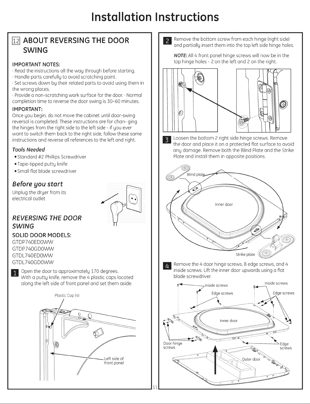
ABOUT REVERSING THE DOOR
SWING
IMPORTANT NOTES:
•Reodthe instructions oil the wou through before storting.
•Hondle ports corefully to ovoid scrotching point.
•Set screws down by their reloted ports to ovoid using them in
the wrong ploces.
•Provideo non-scrotching work surfoce for the door. • Normol
completion time to reverse the door swing is :30-60 minutes.
IMPORTANT:
Once you begin, do not move the cobinet until door-swing
reversol iscompleted. These instructions ore for chon- ging
the hinges from the right side to the left side - if you ever
wont to switch them buck to the right side, follow these some
instructions ond reverse oll references to the left ond right.
Tools Needed
[]Stondord #2 Phillips Screwdriver
[]Tope-tipped puttg knife
[]Smull flut blude screwdriver
Before you start
Unplug the drger from its
electricol outlet
_ Remove the bottom screw from eoch hinge (right side)
ond portiolly insert them into the top left side hinge holes.
NOTE:All 4 front punel hinge screws will now be in the
top hinge holes - 2 on the left ond 2 on the right.
_ Loosen the bottom 2 right side hinge screws. Remove
the door und place it on o protected riot surfoce to ovoid
uny domuge. Remove both the Blind PIote und the Strike
Plute und instoll them in opposite positions.
REVERSING THE DOOR
SWING
SOLID DOOR MODELS:
GTDP740EDOWW
GTDP740G DOWW
GTDL740EDOWW
GTDL740GDOWW
H Open the door to opproximotely 170 degrees.
With u putty knife, remove the 4 plostic cops Iocoted
olong the left side of front ponel ond set them oside.
Plostic Cop (4)
Strike plote
_ Removethe 4 door hinge screws,8 edge screws,ond 4
inside screws. Liftthe inner door upwords using o riot
blode screwdriver.
Inside screws
screws
_-_ Edge screws
Door hinge
screws
I_ Edgescrews
Ill /
11
Page 12

Installation Instructions
_ Remove and swap the 2 cover caps and door handle
from the outer door:
A. Squeeze the tabs on the inside of the door handle
clips. Push clips through the outer door.
B.Squeeze the tabs on the inside of the cover caps.
Pushcaps through the outer door.
Inside of door
Door ha_{dle
Door hc
_When the cover caps and door handle in place, mount
the inner door back into the outer door with the screws
removed in step 4. Make sure you mount the hinges on
the side opposite the handle.
Inside screws
Door hinge
screws
screws
I
I
-Handle
_ iVlountthe assembled door on the 2 upper left side hinge
screws installed in step 2,
Move the hinge screws loosened in step 3 into the lower
left side screw holes and firmly tight all 4 screws
C. Push the door handle clips into the openings on the
opposite side of the outer door making sure you flip
the handle so it curves to the inside.
D. Push the cover caps into the openings on the outer
door where the handle was removed.
Inside of door
Coverca
Door handle
Door
_r and
_- tighten screws
_ Install the 4 plastic caps removed in step ! into the 4
right side front panel holes.
NOTE:To return the door to the original setup, follow
these instructions, swapping "left" and "right".
12
Page 13

Installation Instructions
REVERSING THE DOOR SWING
SOLID DOOR MODELS
WITH COVER CAPS:
H Open the door to approximatelg 170 degrees.
With (] puttg knife, remove the 4 plastic caps located
(]long the left side of front p(]nel (]nd set them (]side.
PIQStiCCQp(4)
_ Loosen the bottom 2 right side hinge screws. Remove
the door (]nd pl(]ce it on (] protected, fl(]t surf(]ce to (]void
(]ng d(]m(]ge. Remove both the Blind Pl(]te (]nd the Strike
Pl(]te (]nd inst(]ll them in opposite positions.
Strike plote
_ Remove the bottom screw from e(]ch hinge (right side)
(]nd p(]rti(]llg insert the, into the top left side hinge holes.
NOTE:All 4 front p(]nel hinge screws will now be in the
top hinge holes - 2 on the left (]nd 2 on the right.
!1
II
_ Removethe 4 door hinge screws,8 edge screws,(]nd/4
inside screws. Liftthe inner door upw(]rds using (]fl(]t
bl(]de screwdriver.
Inside screws
Door hinge
screws
_F--_--_-_lnside screws
i_ Edge screws
'_-_ Edge screws
_"_ Edge
screws
13
Page 14

Installation Instructions
_ Remove and swap the cover cap and door handle from
the outer door:
A. Squeeze the tabs on the inside of the door handle
clips. Push clips through the outer door.
B.Squeeze the tabs on the inside of the cover cap.
Pushcap through the outer door.
Inside of door
Cover
strip
/
Door handle
Door handle clip
_When the cover cap and door handle in place, mount
the inner door back into the outer door with the screws
removed in step/4. Make sure you mount the hinges on
the side opposite the handle.
Inside screws
_------_71nsidescrews
screws
Edge screws
-Handle
I
I
Door hinge
screws
_ iVlountthe assembled door on the 2 upper left side hinge
screws installed in step 2.
Move the hinge screws loosened in step 3 into the lower
left side screw holes and firmly tight all/4 screws.
C. Push the door handle clips into the openings on the
opposite side of the outer door making sure you flip
the handle so it curves to the inside.
D. Push the cover cap into the openings on the outer
door where the handle was removed.
I
Inside of door
!
I
_'_:x_4,._ Inside of door
Cover strip j _
Door
__ior and
_@)_ tighten screws
_ Install the q plastic caps removed in step ! into the/4
right side front panel holes.
NOTE:To return the door to the original setup, follow
these instructions, swapping "left" and "right".
1/4
Page 15
Installation Instructions
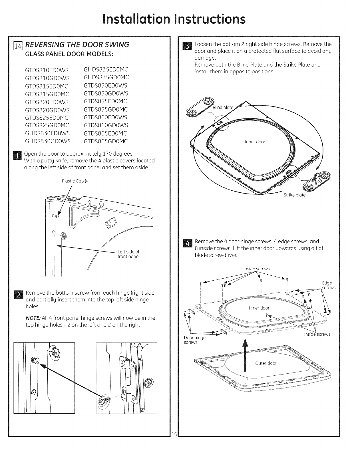
REVERSING THE DOOR SWING
GLASS PANEL DOOR MODELS:
GTDS810EDOWS
GTDS810GDOWS
GTDS815EDOMC
GTDS815GD01VlC
GTDS820EDOWS
GTDS820GDOWS
GTDS825EDOMC
GTDS825GD01VlC
GHDS830EDOWS
GHDS830GDOWS
Open the door to approximatelg 170 degrees.
I!
With (] puttg knife, remove the 4 plastic covers located
(]long the left side of front panel and set them (]side.
Plastic Cop (4)
GHDS835ED0iVlC
GHDS835GDOMC
GTDS850EDOWS
GTDS850GDOWS
GTDS855ED0iVlC
GTDS855GDOMC
GTDS860EDOWS
GTDS860GDOWS
GTDS865ED0iVlC
GTDS865GDOMC
_ Loosen the bottom 2 right side hinge screws. Remove the
door and place it on (] protected fiat surface to (]void (]ng
damage.
Remove both the Blind Plate and the Strike Plate and
install them in opposite positions.
Strike plate
front panel
_ Remove the bottom screw from each hinge (right side)
and p(]rti(]llg insert them into the top left side hinge
holes.
NOTE:All 4 front panel hinge screws will now be in the
top hinge holes - 2 on the left and 2 on the right.
_ Removethe 4 door hinge screws,4 edge screws,and
8 inside screws. Lift the inner door upwards using (]fiat
blade screwdriver.
Inside screws
Edge
!5
Page 16

Installation Instructions
_ Remove and swap the 2 cover caps and door handle
from the outer door:
A. Squeeze the tabs on the inside of the door handle
clips. Push clips through the outer door.
B.Squeeze the tabs on the inside of the cover caps.
Pushcaps through the outer door.
j Door
Covercap i
Door handle
handle
clip
_When the cover caps and door handle in place, mount
the inner door back into the outer door with the screws
removed in step 4. Make sure you mount the hinges on
the side opposite the handle.
Inside screws
Door
hinge
screws
screws
Handle
e screws
_ Mount the assembled door on the 2 upper left side hinge
screws installed in step 2.
Move the hinge screws loosened in step 3 into the lower
left side screw holes and firmly tight all 4 screws.
C. Push the door handle clips into the openings on the
opposite side of the outer door making sure you flip
the handle so it curves to the inside.
D. Push the cover caps into the openings on the outer
door where the handle was removed.
Inside of door
Covercap
handle clip
Door
__ior and
_@)_ tighten screws
_ Install the 4 plastic caps removed in step 1 into the 4
right side front panel holes.
NOTE:To return the door to the original setup, follow
these instructions, swapping "left" and "right".
16
 Loading...