

GE GHDA690P01BB, GHDA690P01WW, GHDA690P02BB, GHDA690P02WW, GHDA690P03BB Installation Guide
...Page 1
Installation
Built-In
Instructions
BEFORE YOU BEGIN
Readthese instructionscompletelyand
carefully.
IMPORTANT Observeall
governingcodesand ordinances.
Noteto Installer_Be sureto leavetheseinstructions
forthe consumer'sand localInspector_]use.
Note to ConsumerKeeptheseinstructionswith your
Owner"sManualforfuturereference.
Skill level Installationofthisdishwasherrequires
basicmechanical,Plumbingandelectricalskills.Proper
installationistheresponsibilityoftheinstaller.
Productfailuredueto improperinstallationisnot
coveredunderthe OurDishwasherWarranty.
CompletionTime?1 to3Hours.NewinstaJlations
requiremoretimethanreplacementinstallations.
Dishwasher
IMPORTANT Thedishwasher
MUSTbeinstalledto allowfor future removalfrom
the enclosure if serviceis required.
Ifyoureceived a damageddishwasher,youshould
immediatelycontactyour dealeror builder.
FOR YOUR SAFETY
Readandobserveall CAUTIONSandWARNINGS
shownthroughouttheseinstructions.While performing
installationsdescribedinthisbooklet,gloves,safety
glassesorgogglesshouldbeworn.
WARNING
Toreducethe risk of electrical shock,fire,
or injuryto persons,the installermust
ensurethat thedishwasheris completely
enclosedatthetime ofinstallation.
READ
KEEP
CAREFULLY,
THESE INSTRUCTIONS,
206C1559P148 31-30207 03-10 FL
Page 2

Installation Preparation
PARTS SUPPLIED:
[] Two#8 Phillipsflatheadwood screws, 5/8"long
to securedishwasher to underside of countertop
(inliterature package).
MATERIALS YOU WILL NEED :
[] Ferrule,compressionnutand 90°Elbow (3/8"NPTexternal
thread ononeend, oppositeend sizedtofit water supply)
[] Threadsealtape
[] ULListedwire nuts (3)
Materials For New Installations Only:
[] Air gapfor drainhose, ifrequired
[] Wasteteefor houseplumbing,if applicable
[] Electrical cableor power cord, if applicable
[] Screw type hoseclamps
[] Strain relief for electrical connection.
[] Handshut-off valve
[] Water line3/8"min.copper
[] Couplerfor extending drain line,if applicable
2WoodScrews
9O°Elbow,
Ferruleand
CompressionNut
WasteTee
Air Gap
Hand
Shut-Off
Valve
Electrical Cable
(orPower Cord,if applicable)
Screw Type Strain Relief
Hose Clamps
Thread
SealTape
Wire Nuts (3)
HotWater line
Coupler
TOOLS YOU WILL NEED: _ and1/4__...5/16"[] Phillips head screwdriver Ph __-,__
[] 5/16"and 1/4"nutdriver Head _ Nutdriver
[] 6"Adjustable wrench Screwdriver
[] Level
[] Carpenterssquare 6"Adjustable
[] Safety glasses
[] Flashlight Flashlight
[] Measuring tape _ _nch
[] Bucket to catch water when flushing the line
[] Gloves
For New Installations Only:
[] Tubing cutter SafetyGlasses
[] Drill and appropriate bits Bucket
[]Holesawset _
Gloves
Hole Saw Set
Level
Carpenters
Square
TubingCutter
Measuring Tape
Page 3
Installation Preparation
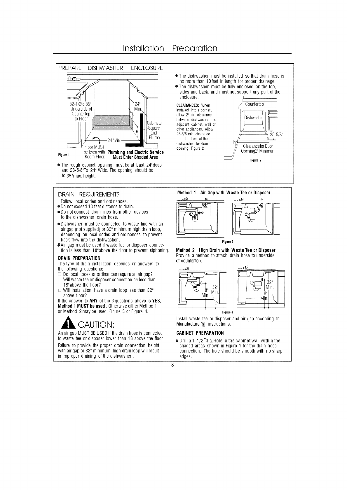
PREPARE DISHWASHER ENCLOSURE
toFloor
°Square
and
Plumb
FloorMUST
Figure1
o Therough cabinetopeningmustbe at least24"deep
and23-5/8'% 24"Wide.Theopeningshouldbe
to35"max.height.
beEvenwith PlumbingandElectricService
RoomFloor. MustEnterShadedArea
• Thedishwashermustbeinstalledso thatdrainhoseis
nomorethan 10feetinlengthforproperdrainage.
• Thedishwashermustbefullyenclosedonthe top,
sidesand back,andmustnotsupportanypart ofthe
enclosure.
CLEARANCES:When
installedinto a corner,
allow 2"min. clearance
between dishwasher and
adjacent cabinet, wal! or
other appliances. Allow
25-5/8"min. clearance
from thefront of the
dishwasher for door
opening. Figure 2
-- Figure 2
DRAIN REQUIREMENTS
Followlocalcodes andordinances.
eDo notexceed10feetdistanceto drain.
oDo notconnectdrainlines fromother devices
tothe dishwasherdrainhose.
oDishwashermustbe connectedto waste linewith an
airgap(notsupplied)or32"minimumhighdrainloop,
dependingon local codesandordinancesto prevent
backflow intothe dishwasher.
_Air gap mustbeusedifwastetee ordisposerconnec-
tion islessthan 18"abovethe floor to preventsiphoning.
DRAIN PREPARATION
The type of drain installation depends on answers to
the following questions:
Do local codes or ordinances require anair gap?
Will waste tee or disposer connection be less than
18"above the floor?
Will installation have a drain loop less than 32"
above floor?
If the answer to ANY of the 3 questions above is YES,
Method 1 MUST be used. Otherwise eitherMethod 1
or Method 2may be used. Figure 3 or Figure 4.
CAUTION:
AnairgapMUSTBEUSEDifthe drainhoseisconnected
towasteteeor disposerlowerthan18"abovethefloor.
Failureto providetheproperdrainconnectionheight
withairgapor32"minimum,highdrainloopwill result
in improperdrainingofthe dishwasher.
Method1 Air GapwithWasteTeeor Disposer
Figure3
Method2 HighDrainwithWasteTeeorDisposer
Provideamethodto attachdrainhosetounderside
ofcountertop.
Figure4
Installwasteteeor disposerandair gapaccordingto
Manufacturer'_ instructions.
CABINET PREPARATION
• Drill a1-1/2"dia.Hole in the cabinetwall within the
shadedareasshownin Figure1for the drainhose
connection.Theholeshouldbe smoothwithno sharp
edges.
Page 4
Installation Preparation
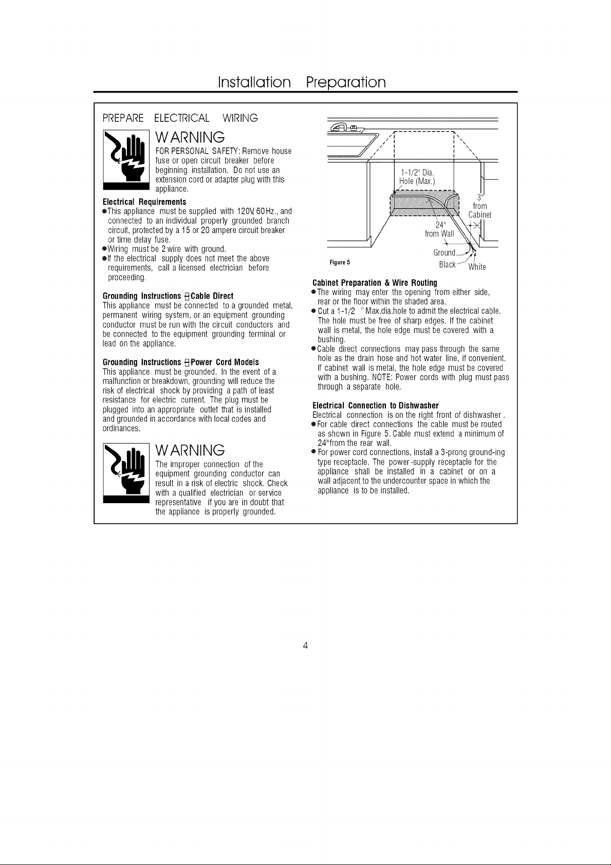
PREPARE ELECTRICAL WIRING
WARNING
FORPERSONALSAFETY:Removehouse
fuse or opencircuit breakerbefore
beginninginstallation.Donotusean
extensioncordoradapterplugwiththis
appliance.
Electrical Requirements
oThis appliance must be supplied with 120V,60Hz., and
connected to an individual properly grounded branch
circuit, protected by a 15 or 20 ampere circuit breaker
or time delay fuse.
oWiring must be 2wire with ground.
elf the electrical supply does not meet the above
requirements, call a licensed electrician before
proceeding.
GroundingInstructionsBCable Direct
Thisappliancemust beconnectedto a groundedmetal,
permanentwiring system,or anequipmentgrounding
conductormustbe runwith the circuit conductorsand
beconnectedto theequipmentgroundingterminalor
leadontheappliance.
GroundingInstructionsBPower CordModels
Thisappliancemust begrounded.Intheeventofa
malfunctionor breakdown,groundingwill reducethe
riskofelectrical shockbyproviding apathofleast
resistancefor electric current.Theplugmust be
pluggedintoanappropriateoutlet thatis installed
andgroundedinaccordancewithlocalcodesand
ordinances.
WARNING
Theimproperconnectionofthe
equipmentgroundingconductorcan
resultin a riskof electricshock.Check
with a qualified electricianor service
representativeif youareindoubtthat
the applianceis properlygrounded.
Figure5
Cabinet Preparation & Wire Routing
eThe wiring may enter the opening from either side,
rear or the floor within the shaded area.
o Cut a 1-1/2 "Max.dia.hole to admit the electrical cable.
The hole must be free of sharp edges. If the cabinet
wall is metal, the hole edge must be covered with a
bushing.
OCable direct connections maypass through the same
hole as the drain hose and hot water line, if convenient.
If cabinet wall is metal, the hole edge must be covered
with a bushing. NOTE:Power cords with plug must pass
through a separate hole.
ElectricalConnectionto Dishwasher
Electricalconnection is on the rightfront of dishwasher.
oFor cable directconnectionsthe cable mustberouted
asshowninFigure5. Cablemustextendaminimumof
24"fromthe rearwall.
e Forpowercord connections,installa3-prongground-ing
typereceptacle.The power-supplyreceptaclefor the
appliance shall be installed in a cabinet or on a
walladjacentto theundercounterspacein whichthe
applianceistobe installed.
Page 5

Installation Instructions
PREPARE HOT WATER LINE
eThe linemayenterfromEitherside,rear or floor
withinthe shadedareashowninFigureF.
oThe line maypassthroughthe sameholeasthe
electrical cableandDrainhose.Or,Outanadditional
1-1/2"dia.holeto accommodatethewaterline.
If powercordwith plug isused,water line Mustnot
passthrough power cord hole.
i \
i x\
i
fl I
Shut-off1-1/2"Dia.
Valve H_
II
Ii
Hot_===
From
Cabinet
CabinetFace--,
Figure 6
Water Line Connection
• Turnoff thewater supply.
Install ahandshut-offvalvein an accessiblelocation,
suchasunderthesink.(Optional,butstronglyrecom-
mendedand maybe requiredby localcodes.)
®Waterconnectionisonthe left side of the dishwasher.
Installthehot waterinletline,usingnolessthan3/8"
O.D.coppertubing.Routethelineasshownin FigureF
andextendforward atleast18"fromrearwall.
• Adjustwaterheaterfor120°Fto150°Ftemperature.
• Flushwater line to cleanout debris.
eThe hotwater supplylinepressuremustbe20-120PSI.
FromFloor _ --
BEFOR YOU BEGIN
Locate andsetasidethepackagecontaining
2 phillips headcountertop mounting screws
and2 additionaltoekickscrews(Iocated in
the literature).
ISTEP11 CHECK DOOR BALANCE
Tocheckthe door balance,holdthe top of the dis-
washerfirmly.
jfo
IooroasoII
'D_rease
Figure 7
• Openthe door slowly,ifthe doordrops when
released,increase spring tension.If the door closes
when released,decreasetension.
ePull the spring adjustment pin outofthe holes,insert
in the nexthighestor lowest holeandtest again.
eAdjust bothdoor springsto the sametension.
eContinue movingthe spring pin until door is balance.
CAUTION:
Openingthe doorwill causethedishwasher
to tipforward. Donotopenthedooruntilyouareready
toinstallthedishwasher.If it is
necessaryto openthedoor,hold
thetop of thedishwashersecurely
with one handandholdthedoor
with the otherhand.
Page 6

Installation Instructions
]ADJUST LEVELING LEGS
oMove the dishwasherclosetotheinstallation
locationandlayit onitsback.
/
\
_ __........
Adjustto
Installation
Height
Figure 8
eMeasure installationheightanddishwasherheight.
Extendlevelinglegsoutfromthe dishwasherbase,
1/4"lessthaninstallationheight.
I.III_T.E_IIIIIIIIIII'.REMOVE TOEKICK
• Removethe2 toekickscrews.Liftoffthe2piece
toekick.
[STEP- 4]INSTALL POWER CORD
Skipthisstepifdishwasherwill bedirectwired.
Thepowercordandconnectionsmustcomplywith
the NationalElectricalCode,Section422and!orlocal
codesandordinances.
oRecommendedpowercordlengthis54'mi n. And
64"max.
A B CheckThatWhite,Blackand
Remove GreenDishwasherWiresAreThreaded
JunctionBox ThruHolein Back
Ground '// _,_¢lqite
........_ jBlack
DUseULListed
WireNuts /
Figure10 C
Power
o Connectincoming............................................CordWiresThru
powercordwhite (orribbed) andTighten
to dishwasherwhite,black
(orsmooth)toblackandgroundto dishwashergreen
wire. UseULlistedwirenuts ofappropriatesize.
• Replacejunction boxcover.Besurewires are not
pinchedunderthe cover.
StrainRelief
Figure9
2-Screws
[STE#5/INSTALL 90 ° ELBOW
Wrap90'_elbowwith threadsealtape.
Installa90"elbowontothe watervalve.
Elbow
Water
Valve
Bracket
Thud
Figure11 SealTape
e Do notoverTighten90'_elbow,water valvebracket
couldbendorwater valvefittingcouldbreak.
e Positiontheend of theelbowto facetherearof the
dishwasher.
Page 7

Installation Instructions
POSITION WATER LINE
AND HOUSE WIRING
OPositionwater supplylineand housewiringonthe
floorof theopeningto avoidinterferencewith base
ofdishwasherandcomponentsunderdishwasher.
Line Wiring
Figure12
iSTEP 7/INSERT DRAIN HOSE
THROUGH CABINET
eUpright thedishwasherandpositioninfront ofthe
opening.Insertdrain hoseintocabinet wall hole.
Ifa powercord is used,guidethe endthrough a
separatehole.
DrainHose
th10'
I]$1T_I_IIIIIIIIII_I]SLIDE DISHWASHER
PARTIALLYINTO CABINET
DOriOTPUSHAGAINSTFRONTPANELWITHKNEES.
DAMAGEWILLOCCUR.
• Sidedishwasherintotheopeningafew inchesata
time.
)o NotPushAgainst
FrontDoorPanelWith
Knee.Damageto The
DoorPanelWillOccur,
oAs youproceed,pullthedrainhosethroughthe
openingunderthesink.Stoppushingwhenthe dish-
washerisafew inchesforwardofadjacentcabinetry.
e Makesuredrainhoseis not kinkedunderthe dish-
washer andthereis no interferencewith the water
lineandwiring or anyothercomponent.
Figure 14
Insulati
Blanket
Hose
H(
Wiring
Cord
(IfUsed)
Figure13
TIP:Positionwaterlineandhousewiringonthefloor
to avoidinterferencewith baseof dishwasher.
Page 8
Installation Instructions
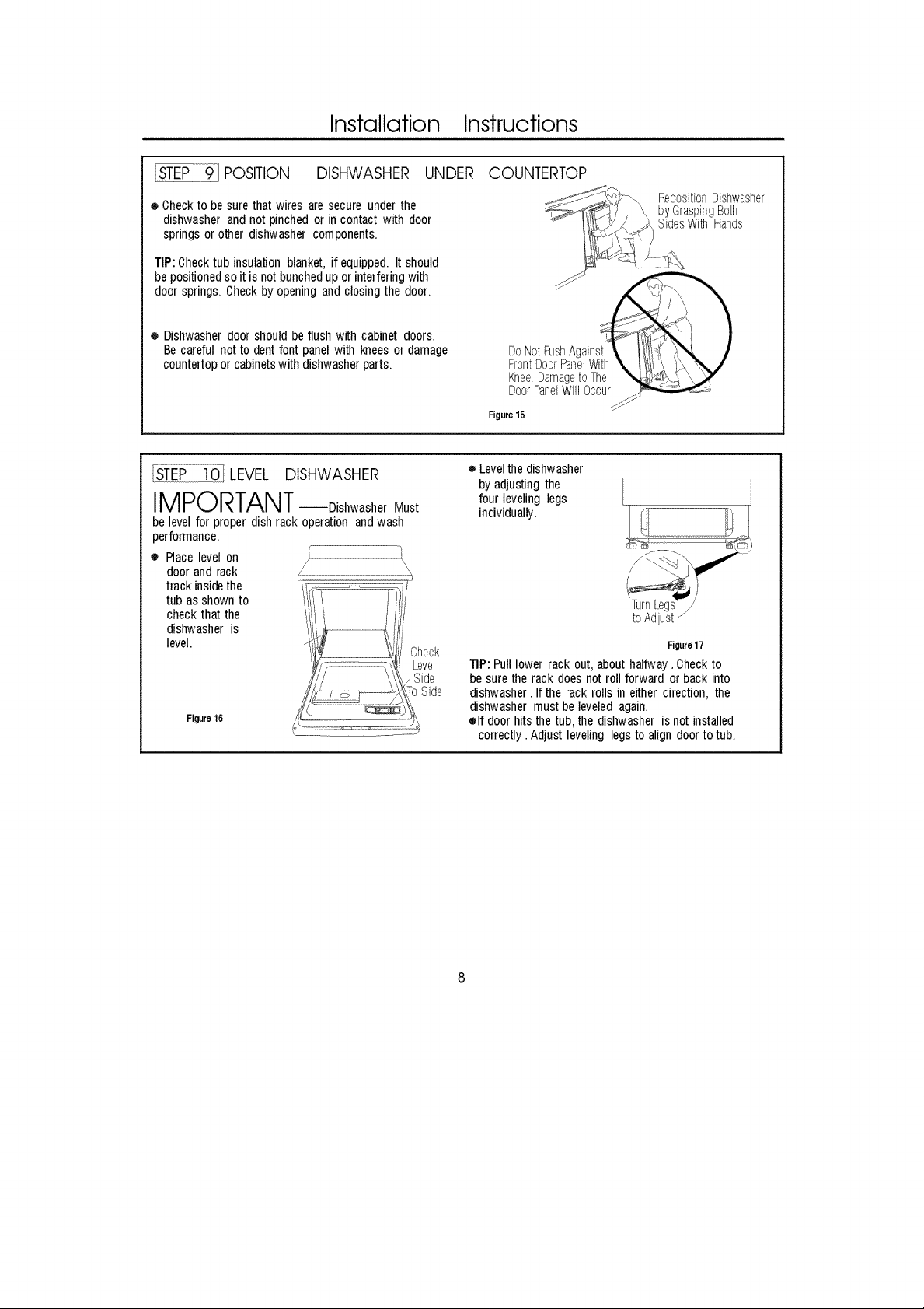
I_Pii_91 POSITION DISHWASHER UNDER
• Checkto be surethat wires are secureunder the
dishwasherandnot pinchedor incontactwith door
springsor otherdishwashercomponents.
TIP:Checktub insulationblanket,if equipped.It should
bepositionedso it is notbunchedup orinterferingwith
door springs.Checkbyopeningand closingthe door.
• Dishwasherdoorshouldbeflushwithcabinet doors.
Becareful notto dentfont panelwith kneesordamage
countertoporcabinetswith dishwasherparts.
LEVEL DISHWASHER
IMPORTANT--DishwasherMust
belevelfor proper dishrack operationandwash
performance.
o Placelevelon
doorandrack
trackinsidethe
tub as shownto
checkthatthe
dishwasheris
level.
Figure16
Check
Level
Side
ToSide
COUNTERTOP
RepositionDishwasher
byGraspingBoth
SidesWith Hands
DoorPanelWillOccur.
Figure15
e Levelthe dishwasher
byadjustingthe
four levelinglegs
individually.
Figure17
TIP:Pulllowerrack out,abouthalfway.Checkto
besuretherackdoesnotrollforwardorbackinto
dishwasher.Ifthe rackrollsineitherdirection,the
dishwashermust beleveledagain.
elf doorhitsthetub,thedishwasherisnotinstalled
correctly.Adjust levelinglegsto aligndoorto tub.
Page 9
Installation Instructions
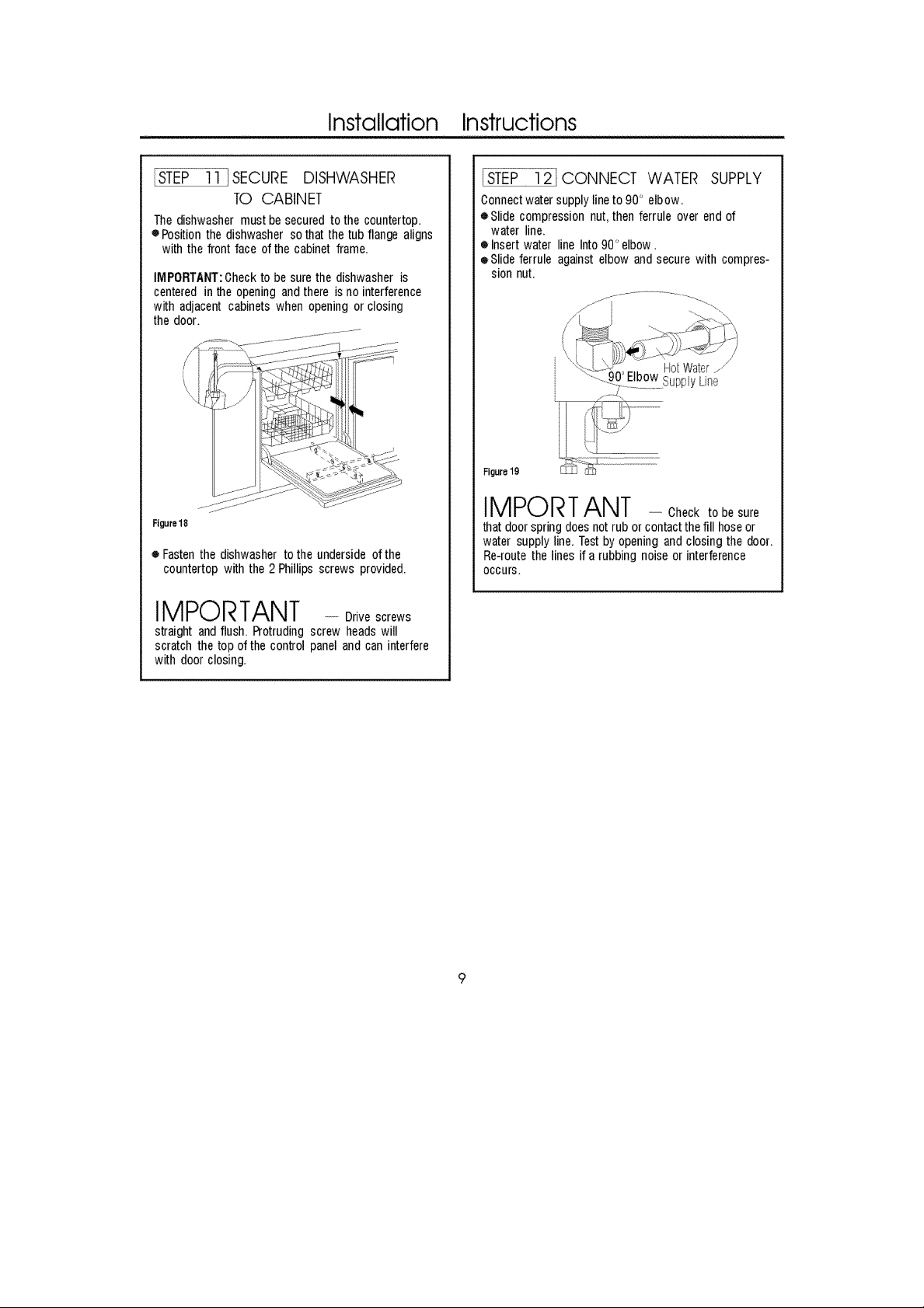
_EP-11-l SECURE DISHWASHER
TO CABINET
Thedishwashermustbesecuredto thecountertop.
oPosition thedishwashersothatthe tubflange aligns
with the front face ofthe cabinet frame.
IMPORTANT:0heckto besurethe dishwasheris
centeredinthe openingandthere is nointerference
with adjacent cabinetswhen opening orclosing
the door.
Figure18
o Fastenthe dishwasherto the undersideof the
countertopwiththe 2Phillipsscrewsprovided.
IMPORTANT - Drivescrews
straight and flush.Protrudingscrew headswill
scratch thetop ofthe controlpaneland caninterfere
with doorclosing.
ISTEP 12] CONNECT WATER SUPPLY
0onnectwatersupplylineto90' elbow.
eSlide compressionnut,then ferrule over endof
water line.
• Insertwater lineInto90" elbow.
oSlide ferrule againstelbow andsecurewith compres-
sionnut.
Figurelg
IMPORTANT - Check tobe sure
thatdoorspringdoesnot ruborcontactthefill hoseor
watersupplyline.Testby openingandclosingthe door.
Re-routethe lines ifa rubbing noiseor interference
occurs.
9
Page 10
Installation Instructions
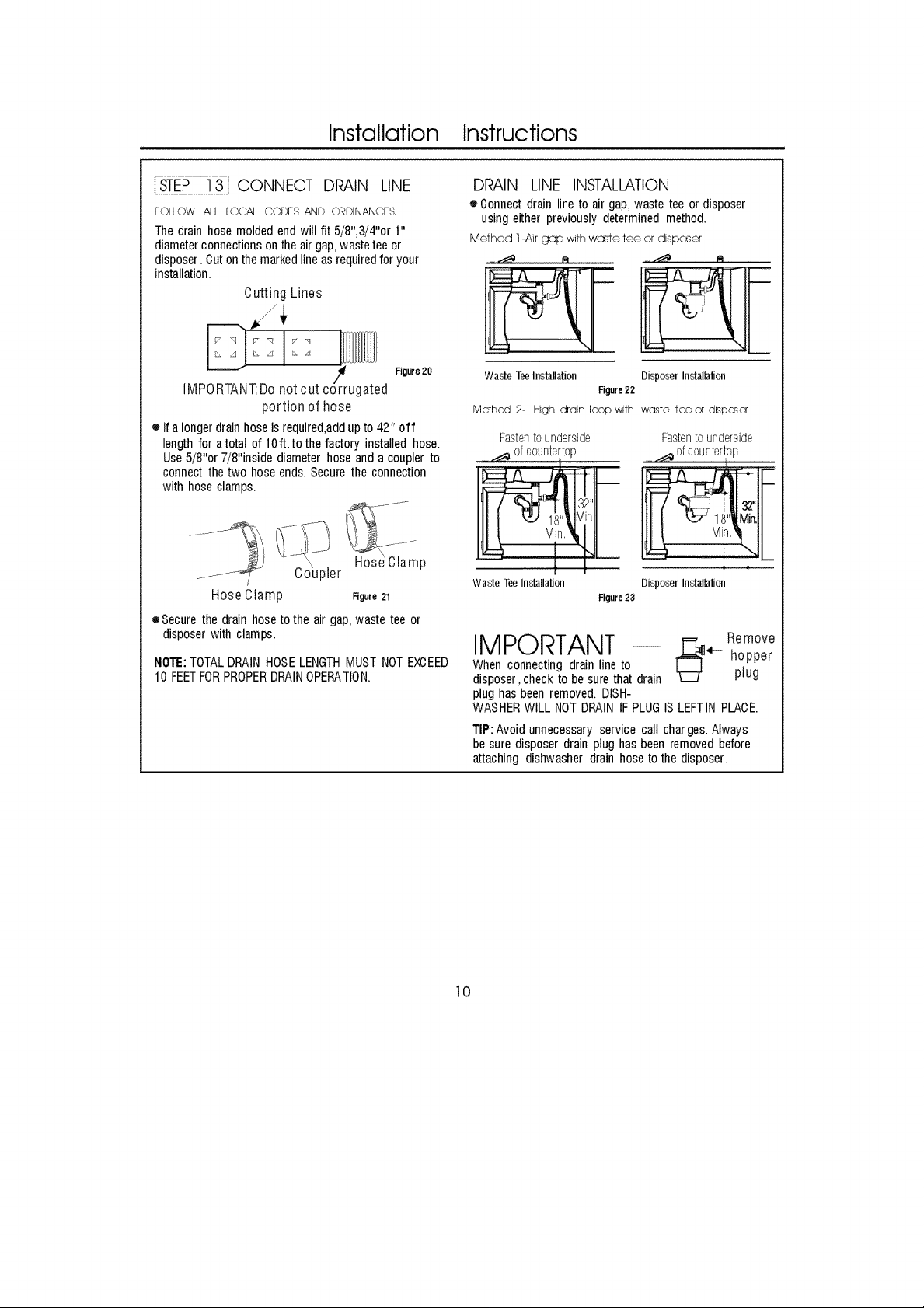
CONNECT DP_,,IN LINE
FOLLOW ALL LOCAL CODES AND C._DINANCES.
Thedrainhosemoldedendwillfit 5/8",3/4"or 1"
diameterconnectionsontheairgap,wastetee or
disposer.Outon themarkedlineasrequiredfor your
installation.
Cutting Lines
Figure20
IMPORTANT:Do not cut corrugated
portion of hose
• Ifa longerdrainhoseis required,addupto42" off
lengthfor atotal of10ft. tothe factoryinstalledhose.
Use5/8"or 7/8"insidediameterhoseand acouplerto
connectthetwo hoseends.Securethe connection
with hoseclamps.
,, HoseClamp
/ Coupler
Hose Clamp Figure21
eSecure the drainhoseto the airgap,waste tee or
disposerwith clamps.
NOTE:TOTALDRAINHOSELENGTHMUSTNOTEXOEED
10 FEETFORPROPERDRAINOPERATION.
DRAIN LINE INSTALLATION
• Oonnectdrain lineto air gap,waste teeor disposer
usingeitherpreviouslydeterminedmethod.
M÷thod 1-Air gap with waste tee or disposer
.,..,"J_ eJ ......_ A
Wade TeeInstallation Disposer Installal]on
Methcd 2- High drain loop with waste fee or disposer
Fastentounderside Fastentounderside
Waste Tp.eInstallal]on Disposer Installal]on
IMPORTANT -- hopper
Whenconnectingdrainlineto plug
disposer,checkto besurethat drain
plug hasbeenremoved.DISH-
WASHERWILL NOTDRAINIFPLUGISLEFTIN PLAOE.
TIP:Avoidunnecessaryservice call charges.Always
be suredisposer drain plughasbeenremovedbefore
attachingdishwasherdrainhosetothedisposer.
!
Figure22
Figure23
_i._ ofc0Unterl0D"
/
Remove
10
Page 11

Installation Instructions
[STEP 14] CONNECT POWER
SUPPLY
Skipthisstepif equippedwithpowercord.
Verifythatpoweristurnedoffatthesource,
oRernovejunction box Coyer'A"
oLocatethethreedishwasherwires,(white,blackand
green)with strippedends.Insertdishwasherwires
throughthesmall holein theJunctionBo×"B"
eSecure housewiring tothebottomofthejunction
boxwitha strainRelief'c"
oUsewire nutstoconnectincominggroundto green,
whitetowhite andblackto Black"D"
eReplacejunctionboxcover"E",checktobesure
thatwiresare notpinchedunderthe cover.
A B CheckThatWhite,Blackand
Remove GreenDishwasherWiresAreThreaded
JunctionBox ThruHoleinBack
Cover
Ground White
......,,.,_ Black
DUseULListed 't ,,
WireNuts C
Figure 23
E.ReplaceJunctionBoxCover
\
insertPower
CordWiresThru
StrainRelier
andTighten
WARNING
Ifhousewiring isnot2-wirewith
ground,agroundmustbeprovided
bythe installer.Whenhousewiring
is aluminum,besureto useULListed
anti-oxidantcompoundandaluminum-
to-copper connectors
PRE-TESTCHECKLIST
Reviewthislist afterinstalling yourdishwasherto
avoidchargesfora servicecallthatisnotcovered
byyourwarranty.
Checkto besurePoweris OFF.
{71Opendoorandremoveall foamandpaper
packaging.
l, LocatetheOwner's manualintheliterature
package.
!] Readthe Owner's Manualforoperating
instructions.
Checkdooropeningandclosing.If doordoesnot
openandclose freely ortends to fall, check spring
adjustments.SeeStep1.
Checkto besurethat wiring is secure underthe
dishwasher,not pinchedorincontactwith door
springsor othercomponents.SeeStep9.
Checkdooralignmentwith tub. Ifdoorhitstub,
leveldishwasher.SeeStep10.
Pulllowerrackout,abouthalfway . Checktobe
sureit doesnotroll backorforwardonthe door.
Iftherack moves,adjustlevelinglegs.SeeStep10.
Checkdooralignmentwith cabinet.If door hits
cabinet,repositionor relevel dishwasher.See
Step10.
Verifywater supplyand drainlinesarenot kinked
or in contactwithother components.Contactwith
motoror dishwasherfTamecouldcausenoise.
SeeStep8.
Turn on the sink hot water faucet and verify water
temperature. Incoming water temperature Must
Be between 120'1=and 150 F.AMinimum of 120F
temperature is required for best wash perfor-
mance. See" Prepare Hot Water Line'_ page 5.
Add 2 quarts of water to the bottom of the dish-
washer to lubricate the pump seal.
Turnonwatersupply.Checkfor leaks. Tighten
connectionsif needed.
!3
Removeprotectivefilm if presentfrom thecontrol
panelanddoor.
11
Page 12
Installation Instructions
[ STEP] 6 ]DISHWASHER WETTEST
[] Turn on power supply(or plug power cord into outlet, if equipped).
[] Select " Normal wash" program.
[] Close the door.
[] Checkto be sure that water enters the dishwasher.if water does not enter the dishwasher, checkto be sure that
water and power are turn on.
[] Check for leaks under the dishwasher.if aleak is found,turn power supply off,then tighten connections.Restore
power afterleak is corrected.
[] Check for leaks.around the door. Aleakaroundthe door could becaused by door rubbing or hitting against
adjacent cabinetry. Reposition the dishwasher if necessary.See step 9.
[] The dishwasher will drain and turn off about 5 to 7 minutes after the first fill.C heck dainlines, if leaks are found,turn
power off at the breaker and correct plumbing as necessary.Restore power ater corrections are made.See Step 12.
[] Open dishwasher door and make sure most of the water has drained.if not,checkthat disposer plug has been
removed and/or air gap is not plugged.See Step 13.Also chek drain line for kinking.
[] Run the dishwasher through another fill and drain cycle .Check for leaks and correct if require.
[] At the end of drain, Press reset button.
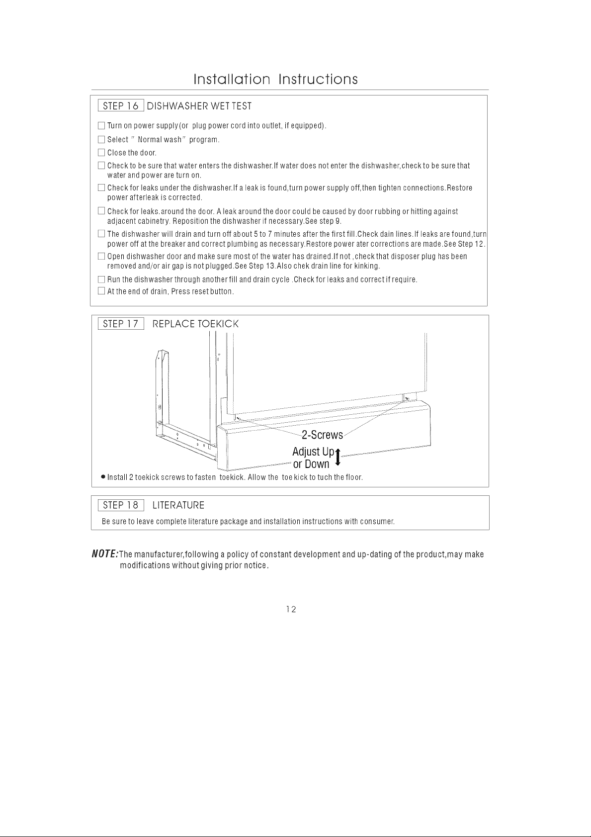
[STEP]7 ] REPLACETOEKICK
2-Screws
Adjust Up.
ii .......................or Down
elnstall 2 toekiok screws to fasten toekiok. Allow the toe kick to tuch the floor.
[STEP]8 ] LITERATURE
Be sure to leave complete literature package and installation instructions with consumer.
NOTE:The manufacturer, following a policy of constant development and up-dating ofthe product,may make
modifications without giving prior notice.
12
 Loading...