

Page 1
GEAppliances.com
Safety Instructions ............2, 3
Operating Instructions
Features ..........................4, 5
Controls ..........................6–9
Dispenser* ......................... 10
Autofill* ............................11
Water Filter ........................12
Fresh Food Storage Options .....13,14
Climate Zone & Temperature
Controlled Drawer ...............15,16
Freezer ............................17
Automatic Ice maker ...............18
Care and Cleaning ................ 19
Replacing the Lights ................20
Installation Instructions
Preparing to Install the
Bottom Freezer
Re frigerator ....................21, 22
Installing the Refrigerator .......23–33
Installing the Water Line ........34–36
Troubleshooting Tips ......38, 39
Normal Operating Conditions .......37
Truth or Myth .................. 40, 41
Consumer Support
Warranty ..........................42
RPWFE Water Filter Cartridge Limited
Warranty .........................43
Performance Data Sheet ...........44
Consumer Support ........Back Cover
Owner’s Manual and
Installation Instructions
GE and GE Profile™ models
Models that start with PFE, GFE, DFE,
and GNE are Standard Depth Models (SD)
Models that start with GYE, PYE and PWE
are Counter Depth Models (CD)
Réfrigérateurs
Manuel d’utilisation
et instructions
d’installation
Modèles GE et GE Profile™
La section française commence à la
Les numéros de modèle commençant par PFE, GFE,
Les numéros de modèle commençant par GYE, PYE
et PWE sont des modèles de profondeur
DFE, et GNE sont des modèles
de profondeur normale (PN).
de comptoir (PC).
Refrigeradores
page 45
Manual del Propietario e
Instrucciones de Instalación
GE y GE Profile™ modelos
*Select Models Only
La sección en español empieza en la
página 90
Los modelos que comienzan con las letras
PFE, GFE, DFE, y GNE son Modelos con
Write the model and serial
numbers here:
Model # ____________________
Serial # ____________________
Find these numbers on a label
on the left side, near the middle
of the refrigerator compartment.
Los modelos que comienzan con las
letras GYE, PYE y PWE son Modelos con
Profundidad Estándar (SD)
Profundidad de Mesada (CD)
Refrigerators
239D4106P020 49-60716 08-14 GE
Page 2
IMPORTANT SAFETY INFORMATION.
READ ALL INSTRUCTIONS BEFORE USING.
SAFETY
IMPORTANT SAFETY INFORMATION READ ALL INSTRUCTIONS BEFORE USING
GE Appliances website
For more information on your refrigerator’s operation, visit
www.GEAppliances.com
REFRIGERATOR SAFETY INFORMATION
This is the safety alert symbol. This symbol alerts you to potential hazards that can kill or hurt you and others. All safety
messages will follow the safety alert symbol and the word “DANGER”, “WARNING”, or “CAUTION”. These words are defined as:
Indicates a hazardous situation which, if not avoided, will result in death or serious injury.
DANGER
Indicates a hazardous situation which, if not avoided, could result in death or serious injury.
WARNING
Indicates a hazardous situation which, if not avoided, could result in minor or moderate injury.
CAUTION
IMPORTANT SAFETY INSTRUCTIONS
WARNING
To reduce the risk of fire, explosion, electric shock, or injury when using your
refrigerator follow these basic safety precautions:
This refrigerator must be properly installed and located in
accordance with the Installation Instructions before it is used.
Unplug the refrigerator before cleaning and making repairs.
NOTE: Repairs must be performed by a qualified Service
Replace all parts and panels before operating.
Because of potential safety hazards under certain conditions,
To prevent suffocation and entrapment hazards to children,
Do not store or use gasoline or other flammable vapors and
Power to the refrigerator cannot be disconnected by any
Professional.
we strongly recommend against the use of an extension cord.
However, if you must use an extension cord, it is absolutely
necessary that it be a UL-listed (in the United States) or a CSA
certified (in Canada), 3-wire grounding type appliance extension
cord having a grounding type plug and outlet and that the
electrical rating of the cord be 15 amperes (minimum) and 120
volts.
Remove the fresh food and freezer doors from any refrigerator
before disposing of it or discontinuing its use.
liquids in the vicinity of this or any other appliance.
setting on the control panel, refrigerator must be unplugged to
remove power.
Do not allow children to climb, stand or hang on the door handles
or the shelves in the refrigerator. They could seriously injure
themselves.
In refrigerators with automatic ice makers, avoid contact with
the moving parts of the ejector mechanism, or with the heating
element that releases the cubes. Do not place fingers or hands
on the automatic ice making mechanism while the refrigerator is
plugged in.
Do not clean glass shelves or covers with warm water when
they are cold. Glass shelves and covers may break if exposed
to sudden temperature changes or impact, such as bumping or
dropping. Tempered glass is designed to shatter into many small
pieces if it breaks.
Keep fingers out of the “pinch point” areas; clearances between
the doors and between the doors and cabinet are necessarily
small. Be careful closing doors when children are in the area.
Do not touch the cold surfaces in the freezer compartment when
hands are damp or wet, skin may stick to these extremely cold
surfaces.
Do not refreeze frozen foods which have thawed completely.
Use a sturdy glass when dispensing ice (on models with ice
dispenser)
INSTALLATION
WARNING
Keep flammable materials and vapors, such as gasoline, away from refrigerator. Failure to do so can
result in fire, explosion, or death.
Explosion Hazard.
2
Page 3
GEAppliances.com
SAFETY (CONT.)
WARNING
Tip Over Hazard.
Built-in style models (model PYE, CYE, GYE, PWE, CWE, and ZWE) are top heavy, especially with any
doors open. These models must be secured with the anti-tip floor bracket to prevent tipping forward,
which could result in death or serious injury. Read and follow the entire installation instructions for
installing the anti-tip floor bracket packed with your refrigerator.
CONNECTING ELECTRICITY
WARNING
Plug into a grounded 3-prong outlet
Do not remove the ground prong
Do not use an adapter
Failure to follow these instructions can result in death, fire, or electrical shock.
Electrical Shock Hazard.
Do not, under any circumstances, cut or remove the third (ground) prong from the power cord.
For personal safety, this appliance must be properly grounded.
The power cord of this appliance is equipped with a 3-prong
(grounding) plug which mates with a standard 3-prong
(grounding) wall outlet to minimize the possibility of electric
shock hazard from this appliance.
Have the wall outlet and circuit checked by a qualified
electrician to make sure the outlet is properly grounded.
Where a standard 2-prong wall outlet is encountered, it is
your personal responsibility and obligation to have it replaced
with a properly grounded 3-prong wall outlet. Do not use an
adapter.
The refrigerator should always be plugged into its own
individual electrical outlet which has a voltage rating that
matches the rating plate.
A 115 Volt AC, 60 Hz, 15- or 20-amp fused, grounded electrical
supply is required. This provides the best performance and
also prevents overloading house wiring circuits which could
cause a fire hazard from overheated wires.
Never unplug your refrigerator by pulling on the power cord.
Always grip plug firmly and pull straight out from the outlet.
Repair or replace immediately all power cords that have
become frayed or otherwise damaged. Do not use a cord that
shows cracks or abrasion damage along its length or at either
end.
When moving the refrigerator away from the wall, be careful
not to roll over or damage the power cord.
PROPER DISPOSAL OF YOUR OLD REFRIGERATOR
WARNING
Remove fresh-food and freezer doors from the refrigerator, prior to disposal. Failure to do so can
result in child entrapment which can lead to death or brain damage.
IMPORTANT:
Suffocation and child entrapment hazard.
Child entrapment and suffocation are not problems of the past.
Junked or abandoned refrigerators are still dangerous even if
they will sit for “just a few days.” If you are getting rid of your old
refrigerator, please follow the instructions below to help prevent
accidents.
Before You Throw Away Your Old Refrigerator or
Freezer:
Take off the fresh food and freezer doors.
Leave the shelves in place so that children may not easily climb
inside.
Refrigerants
All refrigeration products contain refrigerants, which under
federal law must be removed prior to product disposal. If you
are getting rid of an old refrigeration product, check with the
company handling the disposal about what to do.
READ AND FOLLOW THIS SAFETY INFORMATION CAREFULLY.
SAVE THESE INSTRUCTIONS
3
Page 4
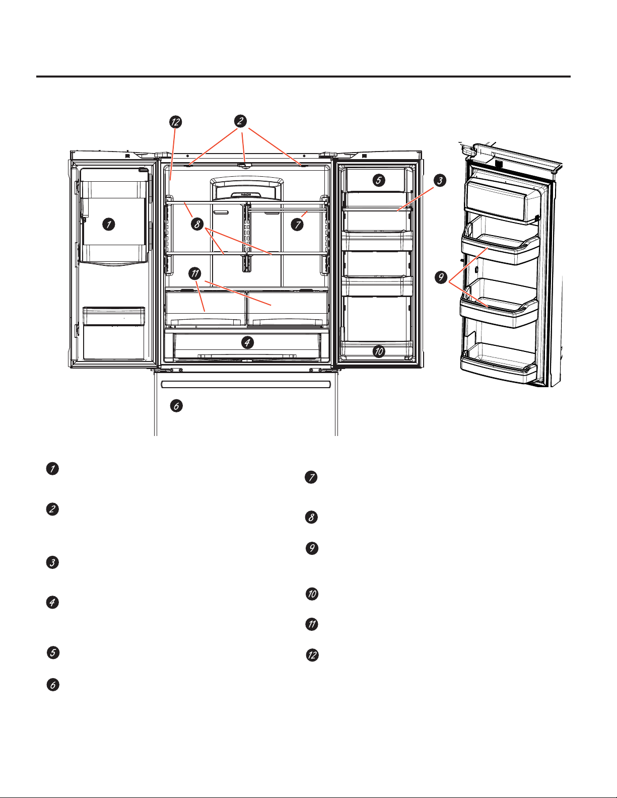
About the features. *
Space-saving ice maker*
Ice maker and bin are located on the door creating more usable
storage space.
Showcase LED lighting
LED lighting is positioned throughout the interior to spotlight areas
in the refrigerator. LEDs are located under the fresh food door to
light the freezer when opened.
Drop-down tray*
Allows for extra door storage when you need it and tucks away
when you don’t.
Full-width temperature controlled drawer
(on some models)
Adjustable temperature control bin that can accommodate
larger items.
Dairy bin*
Separate compartment for your items.
Dual ice maker/Ice bin (on some models)
An ice maker in both compartments gives you
more ice whenever you need it
.
*Select Models Only
QuickSpace™ shelf*
Functions as a normal full-sized shelf when needed and easily slides
back to store tall items below.
Spillproof shelves
Designed to capture your spills for easier clean up.
Anti-slip Mat*
Liner that captures spills, keeps containers from shifting when the door
is opened and is easily removable for cleaning.
Removable door bin
Can be removed for those with a wall limiting the door opening.
Climate zone bin
Separate bins for produce storage.
Water filter*
Filters water & Ice
4
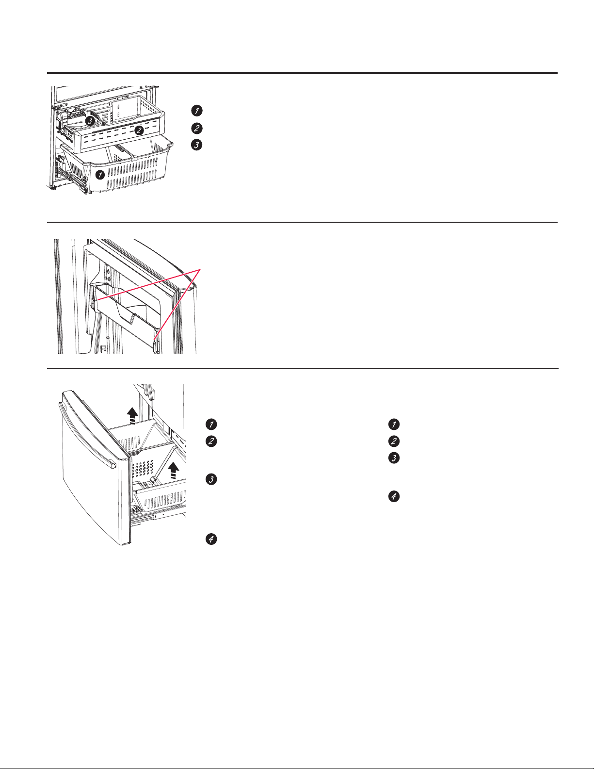
Page 5
About the features. * GEAppliances.com
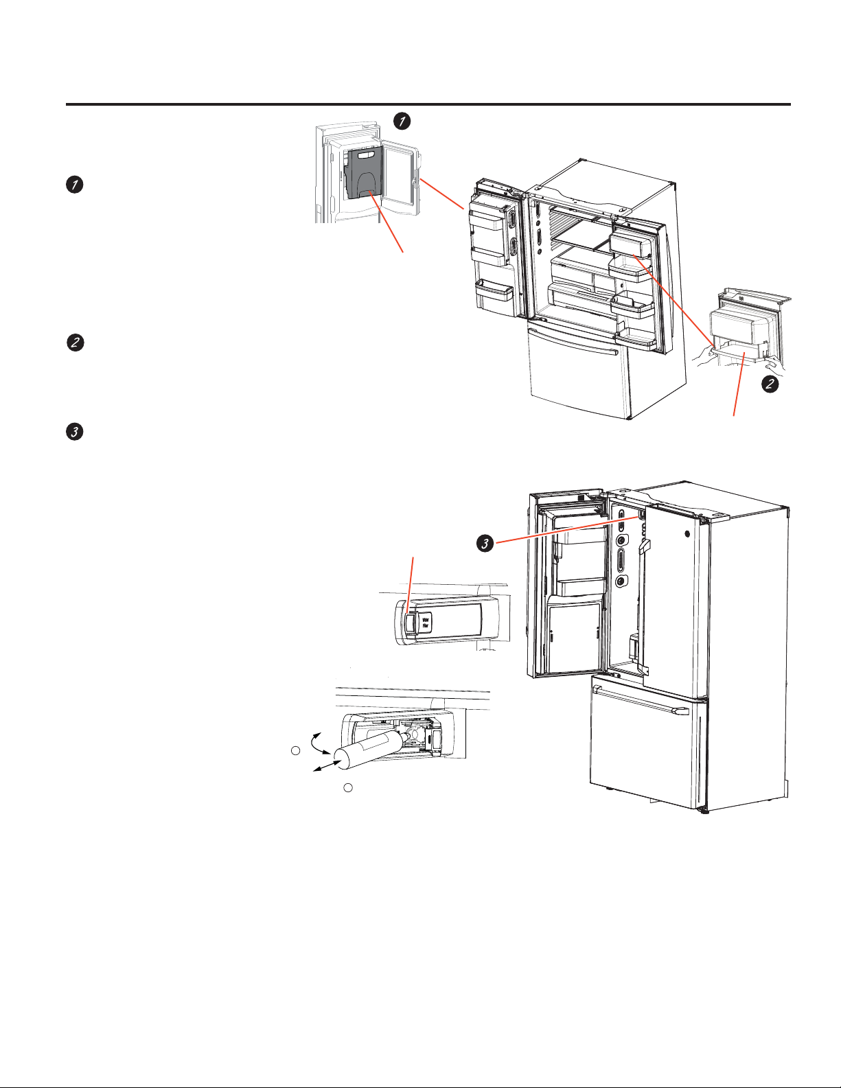
Door ice bin*
1. Open left fresh food door.
2. Pull down latch to release bin door.
3. Using handhold lift ice bucket up and
out to clear locators in bottom of bin.
4. To replace the ice bucket, set it on the
guide brackets and push until the ice
bucket seats properly.
5. If bucket cannot be replaced, rotate
the Ice Bucket Fork 1/4 turn clockwise.
Drop down dairy bin*
1. Open right fresh food
2. Depress both buttons on lower sides
and bin will drop down.
3. Reverse to reinstall.
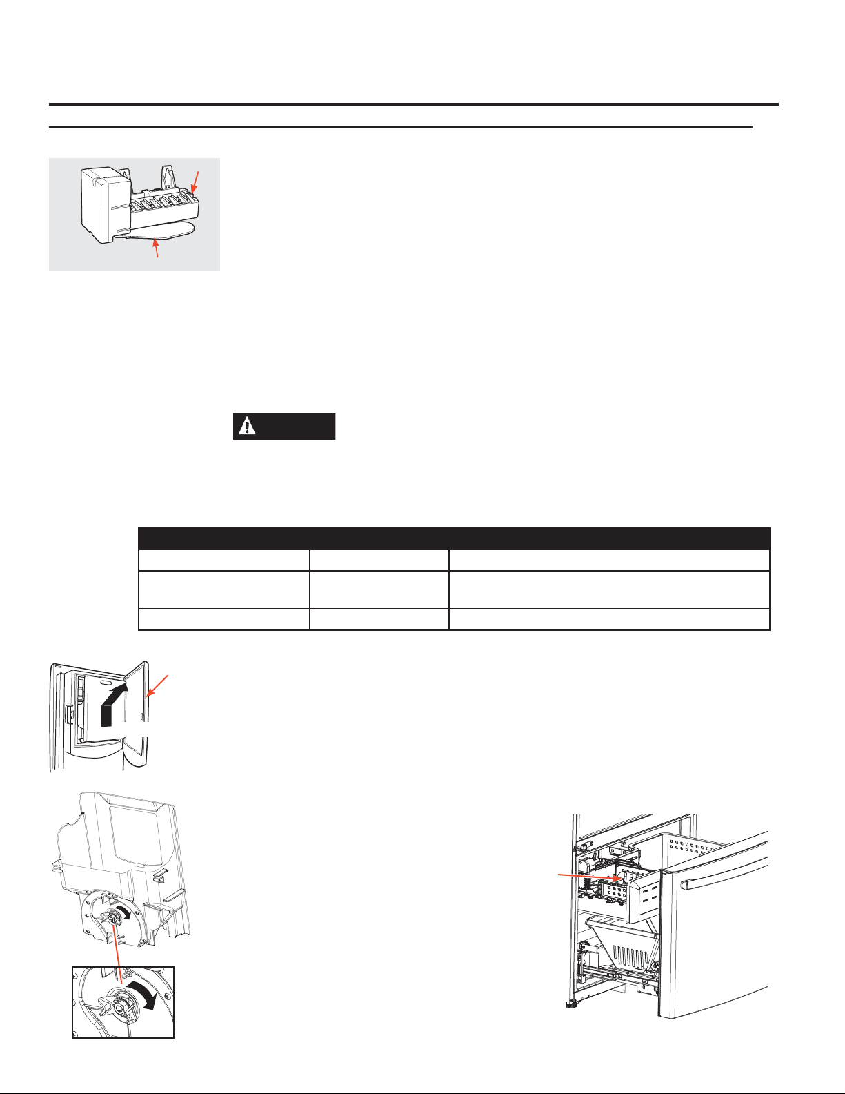
Ice/water filter
Remove filter/bypass plug
Push the indent on the cover and open
filter door. Pull out on filter/bypass plug
and pull straight back to remove.
Installing the filter cartridge
Push the indent at the bottom of the
cover and open. Lift door and align tabs
on filter to filter/holder and push filter into
place.
Ice bucket
Push in and
pull open
Latch
Drop down tray
(tray open)
*Select Models Only
Swing
1
Push \ Pull
2
5
Page 6
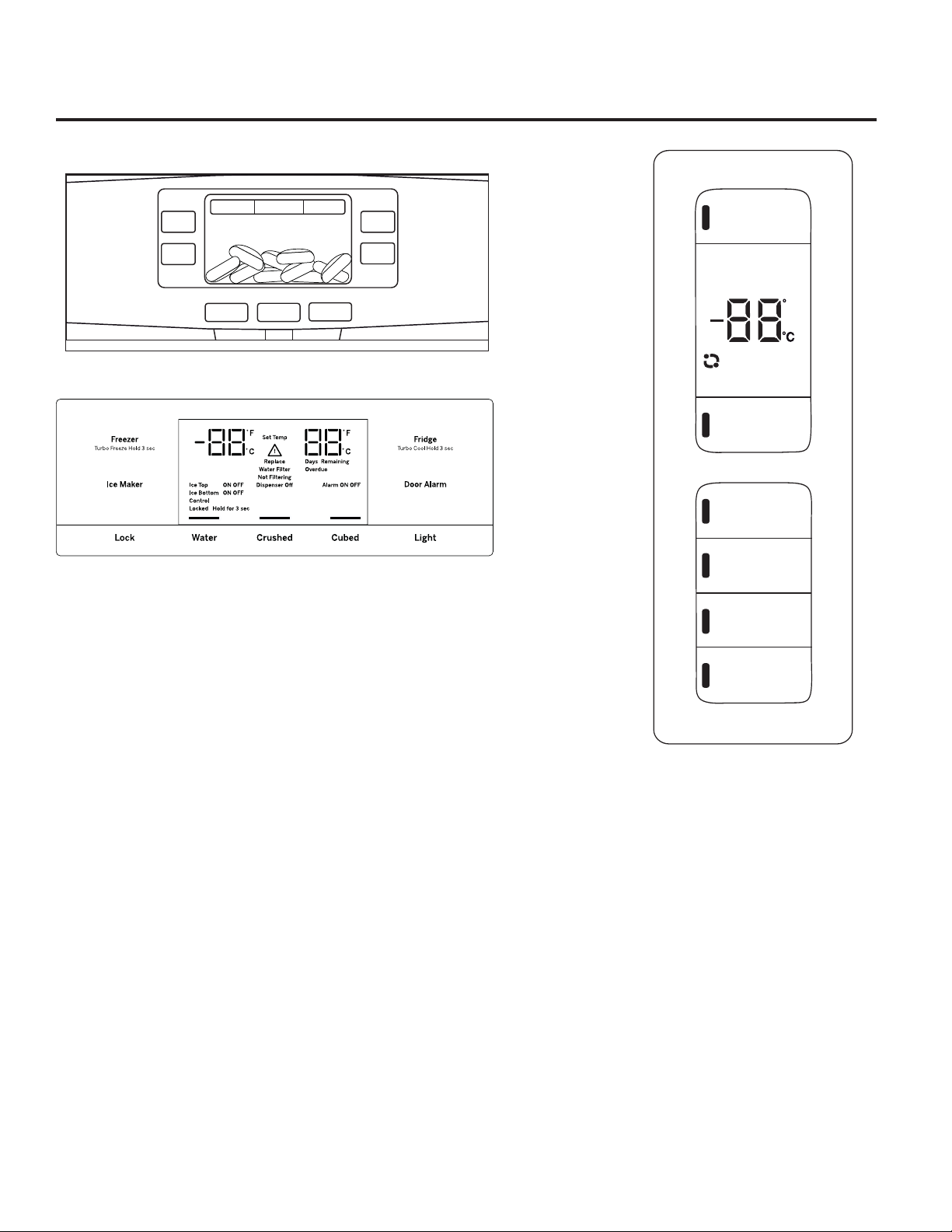
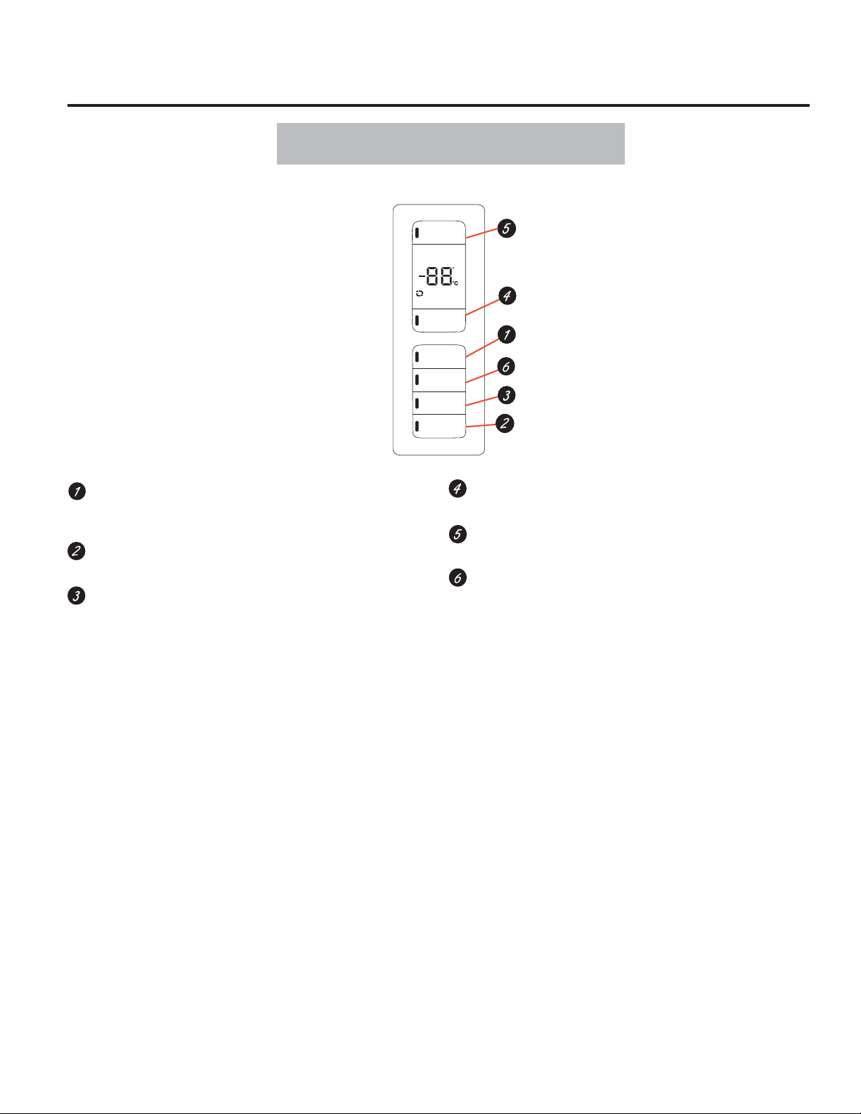
About the controls with temperature settings.
PFE28,PYE22P Control Style A, LCD External Control
Control
Lock
Light
Temperature
Cubed
Water
Express Mode
Crushed
Settings
Precise Fill
Auto Fill
Cubed
GFE28, GFE26, DFE28, GYE22 Control Style B, External Control
Refrigerator
Hold 3 Sec for °F/°C
Recommended: 37 °F
Actual Set
F
Energy Smart
Recommended: 0°F
Freezer
Energy Smart Override
Hold 3 Seconds
Door Alarm
Ice Maker
GNE29, PWE23 Control Style C, Internal Control
Lock Controls
Hold 3 Seconds
Reset Filter
Hold 3 Seconds
NOTE: The refrigerator is shipped with protective film covering the temperature controls.
If this film was not removed during installation, remove it now.
The temperature controls are preset in the factory at 37°F for the refrigerator compartment and 0°F for the freezer
compartment. Allow 24 hours for the temperature to stabilize to the preset recommended settings.
The temperature controls can display both the SET temperature as well as the actual temperature in the refrigerator and
freezer. The actual temperature may vary slightly from the SET temperature based on usage and operating environment.
6
Page 7
About the controls with temperature settings. GEAppliances.com
Changing the Temperature for Control Style A
To Change the Refrigerator Temperature:
Access By: Temperature Button
Activate By: Below the word “Refrigerator”, use the arrows to
select the desired temperature. Press DONE when finished to
return to HOME screen.
To Change the Freezer Temperature:
Access By: Temperature Button
Activate By: Below the word “Freezer”, use the arrows to
select the desired temperature. Press DONE when finished to
return to HOME screen.
Temperature
Temperature
Changing the Temperature for Control Style B
To change the temperature, press and release the Freezer
or Fridge pad. The display will show the set temperature. To
change the temperature, press either the Freezer or Fridge
pad until the desired temperature is displayed.
To turn OFF cooling system, access SETTINGS from the
HOME screen. Page over and tap COOLING SYSTEM ON.
Press DONE to return to HOME screen.
To turn ON cooling system, access SETTINGS from the HOME
screen. Page over and tap COOLING SYSTEM OFF. Press
DONE to return to HOME screen.
Turning the cooling system off stops the cooling to
refrigerator, but it does not shut off the electrical power.
To turn OFF cooling system, press and hold Fridge and Ice
Maker simultaneously for 3 seconds. When the cooling
system is OFF the display should read OFF.
Changing Temp. for Control Style C
Temperature Display is located on inside of left-hand
refrigerator door. To change the temperature, press and
release the REFRIGERATOR or FREEZER pad. The ACTUAL
TEMP light will come on and the display will show the actual
temperature. To change the temperature, tap either the
REFRIGERATOR or FREEZER pad until the desired
temperature is displayed.
To turn OFF cooling system, press and hold the
REFRIGERATOR and FREEZER pads simultaneously for 3
seconds. When the cooling system is OFF the display should
read OFF.
NOTE: For optimal temperature performance, we recommend to avoid placing food items directly at the air flow vents of the
fresh food air tower and thus blocking the air flow.
To turn ON cooling system, press either REFRIGERATOR or
FREEZER pad. The display will show the preset temperature
settings of 37°F for refrigerator and 0°F for freezer. Turning
the cooling system off stops the cooling to refrigerator, but it
does not shut off the electrical power.
7
Page 8
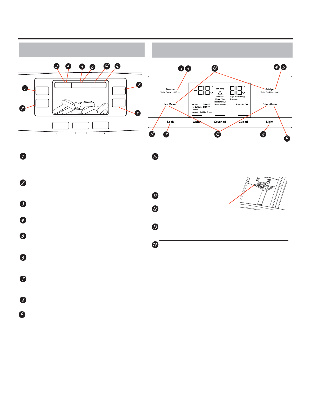
About the controls - features.
Control Style A, External Controls
Control
Lock
Light
Temperature
Cubed
Water
Express Mode
Crushed
Settings
Cubed
PFE28, PYE22P
Precise Fill
Auto Fill
Hands-free Autofill*
Hands-free Autofill uses sensors to monitor
container height to automatically dispense filtered
water without having to activate the paddle.
PreciseFill setting*
Precisely dispenses filtered water in accurate measurements
in ounces, cups, quarts, or liters using paddle.
Refrigerator temp control
Adjust freezer compartment temperature.
Fresh food temp control
Adjust fresh food compartment temperature.
TurboFreeze™ setting
Activate TurboFreeze to quickly restore freezer
temperatures after frequent door openings.
TurboCool™ setting
Activate TurboCool to quickly restore fresh food
temperature after frequent door openings.
Lock controls
Press and hold 3 seconds to lock out ice and water dispenser
and all feature and temperature buttons.
LED dispenser light
LED lighting that can be turned on/off to light your dispenser.
Door Alarm
Sounds to alert when the freezer or fresh food doors
have been left open. Press and hold Door Alarm pad and it will toggle
the sound between low, high and off.
Control Style B, External Controls
DFE28, GYE22
Photo upload*
GFE28, GFE26,
Insert USB memory stick to upload personal
photos to the refrigerator LCD screen.
LCD will provide on screen prompts to load
and view slideshow.
Make sure the photos are in the
root directory in your USB.
Ice maker setting
Turn your ice makers on/off.
Cooling system On/Off
Press and hold Fridge & Ice Maker simultaneously for 3 seconds to turn
the cooling system on or off.
USB Cover
Metric/English units
Press and hold Ice Maker & door alarm simultaneously for 3 seconds to
switch between Metric & English units.
Additional settings:
• Photo upload and delete
• Slideshow
• Connected Home ready
• Reset water filter
• Ice maker on/off
• Door alarm
• Sound control
• Cooling system On/Off
• Metric/English units
• Auto fill video turorial
Additional Modes
• Sabbath Mode
Press and hold lock & light simultaneously for 3 seconds to enter/
exit Sabbath mode. Activate Sabbath Mode to turn off interior lights,
temperature control and advanced features. Compressor will run on a
timed defrost when in Sabbath mode.
*Select Models Only
8
Page 9
About the controls - features.* GEAppliances.com
Controls Style C, Internal Controls
Door Alarm
Sounds to alert when the freezer or fresh food doors have
been left open.
Reset Filter*
Hold for 3 seconds after replacing filter.
Lock Controls
Press and hold 3 seconds to lock out ice and water dispenser and all
feature and temperature buttons.
Refrigerator
Hold 3 Sec for °F/°C
Recommended: 37 °F
Actual Set
Energy Smart
Recommended: 0°F
Freezer
Energy Smart Override
Hold 3 Seconds
Door Alarm
Ice Maker
Lock Controls
Hold 3 Seconds
Reset Filter
Hold 3 Seconds
GNE29, PWE23
F
Freezer temp control
Adjust freezer compartment temperature
Refrigerator temp control
Adjust fresh food compartment temperature
Ice maker setting
Turn your ice makers on/off.
*Select Models Only
9
Page 10
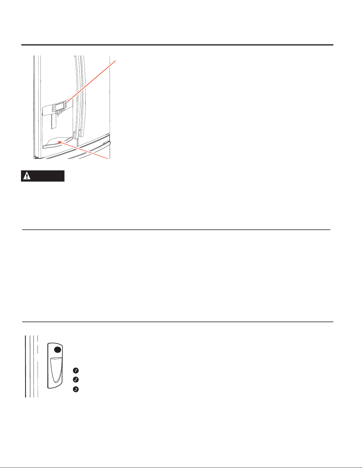
About the dispenser.*
Water & Ice Dispenser
(See About the controls
with temperature settings &
About the control features)
Precise
Fill
Auto
ll
Fi
ck
o
L
rol
t
Con
Light
d
e
Cub
ter
Wa
Dispenser tray
WARNING
Laceration Hazard
Never put fingers or any other object into ice crusher
discharge opening. Doing so can result in contacting the ice
crushing blades and lead to serious injury or amputation
Use a sturdy glass when dispensing ice. A delicate glass may
break and result in personal injury.
If no water is dispensed when the refrigerator is first installed,
there may be air in the water line system. Press the dispenser
paddle for at least five minutes to remove trapped air from the
water line and to fill the water system. To flush out impurities in
the water line, throw away the first six full glasses of water.
To remove Dispenser Tray (Type A Only)
Pull Dispenser Tray out until it stops.
Locate tab in the center on the bottom and push up.
Pull Dispenser Tray assembly out.
Lift metal Dispenser Tray out at center notch to clean.
To remove Dispenser Tray (Type B Only)
Pull Dispenser Tray out.
To reinstall Dispenser Tray (Type A Only)
Place the Dispenser Tray cover on top of catch tray and
position under the two plastic retainers on either side.
Center Dispenser tray, and align with center guides.
Push in until it locks firmly in place.
To reinstall Dispenser Tray (Type B Only)
Center Dispenser Tray and push in until it snaps in place.
Important Facts About Your Dispenser
Do not add ice from trays or bags to the door ice maker
bucket. It may not crush or dispense.
Avoid overfilling glass with ice and use of narrow glasses.
Backed-up ice can jam the chute or cause the door in the
chute to freeze shut. If ice is blocking the chute remove the ice
bucket, poke it through with a wooden spoon.
Beverages and foods should not be quick-chilled in the
door ice maker bin. Cans, bottles or food packages in the
storage drawer may cause the ice maker or auger to jam.
To Use the Internal Water Dispenser*
The water dispenser is located on the
left wall inside the refrigerator compartment.
To dispense water:
Hold the glass against the recess.
Push the water dispenser button.
Hold the glass underneath the
dispenser for 2–3 seconds after
releasing the dispenser button. Water
may continue to dispense after the
button is released.
To keep dispensed ice from missing the glass, put the glass
close to, but not touching, the dispenser opening.
Some crushed ice may be dispensed even though you
selected CUBED ICE. This happens occasionally when a few
cubes accidentally get directed to the crusher.
After crushed ice is dispensed, some water may drip from the
chute.
Sometimes a small mound of snow will form on the door in the
ice chute. This condition is normal and usually occurs when you
have dispensed crushed ice repeatedly. The snow will eventually
evaporate.
If no water is dispensed when the refrigerator is first installed,
there may be air in the water line system. Press the dispenser
button for at least 5 minutes to remove trapped air from the
water line and to fill the water system. During this process,
the dispenser noise may be loud as the air is purged from the
water line system. To flush out impurities in the water line,
throw away the first 6 glassfuls of water.
NOTE: To avoid water deposits, the dispenser should be
cleaned periodically by wiping with a clean cloth or sponge.
*Select Models Only
10
Page 11
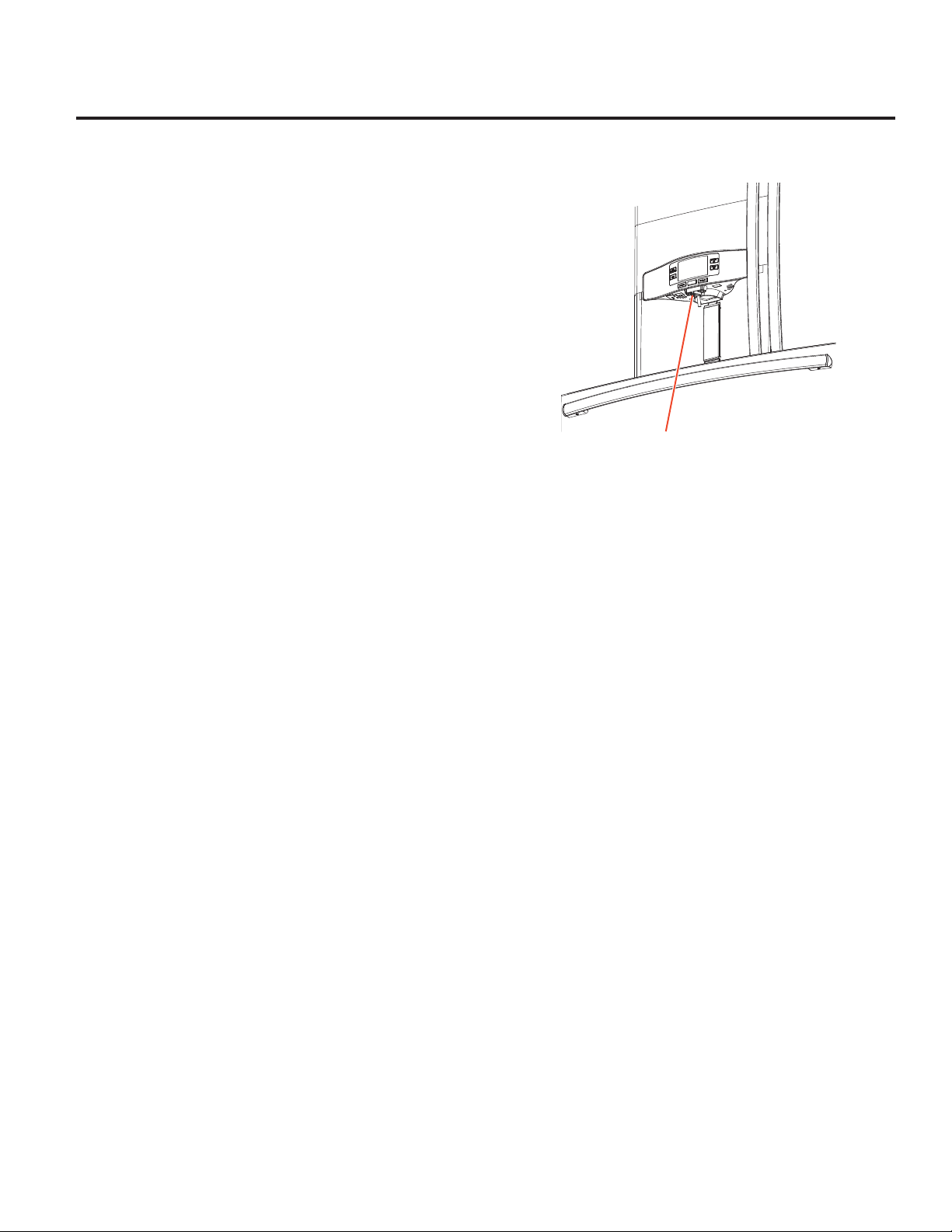
About autofill.*
To Use HANDS FREE AUTO FILL:
• Center container on Recess Dispenser Tray and remove hand
from container
• Press AUTO FILL
To Stop AUTO FILL
• Press CANCEL, to resume filling press AUTO FILL.
Important Facts about AUTO FILL
• For optimum results, use a uniform container between 4-8”
tall and 2-6” wide.
• Container shape, fill level and functionality may vary on
containers taller than 8”.
• Container volumes may vary, if error message “Container
Not Found” is given, try a different container.
• AUTO FILL will time out.
• Handles and garnishes on the rim of the container my cause
overfilling or variation in fill volumes.
• Splashing may occur depending on the location of the
container, water flow rate, container shape, and ice cubes.
• Keep sensors clean with a clean damp cloth, and do not
spray liquid or cleaners directly on sensors
• AUTO FILL works best with household water pressure of 60
to 100 psi.
GEAppliances.com
Sensors
*Select Models Only
11
Page 12
About the GE® RPWFE water filter cartridge.
Water Filter Cartridge
The water filter cartridge is located in the fresh food interior
on the left side wall, near the top.
This product uses radio frequency identification (RFID) to
detect leaks and monitor filter status. The RFID technology is
certified by the FCC.
FCCID: ZKJ-EBX1532P001 ICID: 10229A-EBX1532P001
“This device complies with part 15 of the FCC Rules. Operation is
subject to the following two conditions: (1) This device may not
cause harmful interference, and (2) this device must accept any
interference received, including interference that may cause
undesired operation.”
“This device complies with Industry Canada licence-exempt
RSS standard(s). Operation is subject to the following two
conditions: (1) this device may not cause interference, and (2)
this device must accept any interference, including interference
that may cause undesired operation of the device.”
When to replace the filter cartridge
The filter cartridge should be replaced every six months or
earlier if 170 gallons of water has been dispensed or the flow of
water to the dispenser or icemaker decreases.
Touch Screen Models: A filter status message will appear on
the screen when the water filter needs to be replaced. The filter
status will automatically update when the filter is replaced.
Non-touch Screen Models: A filter indicator light will illuminate
on the screen when the water filter needs to be replaced.
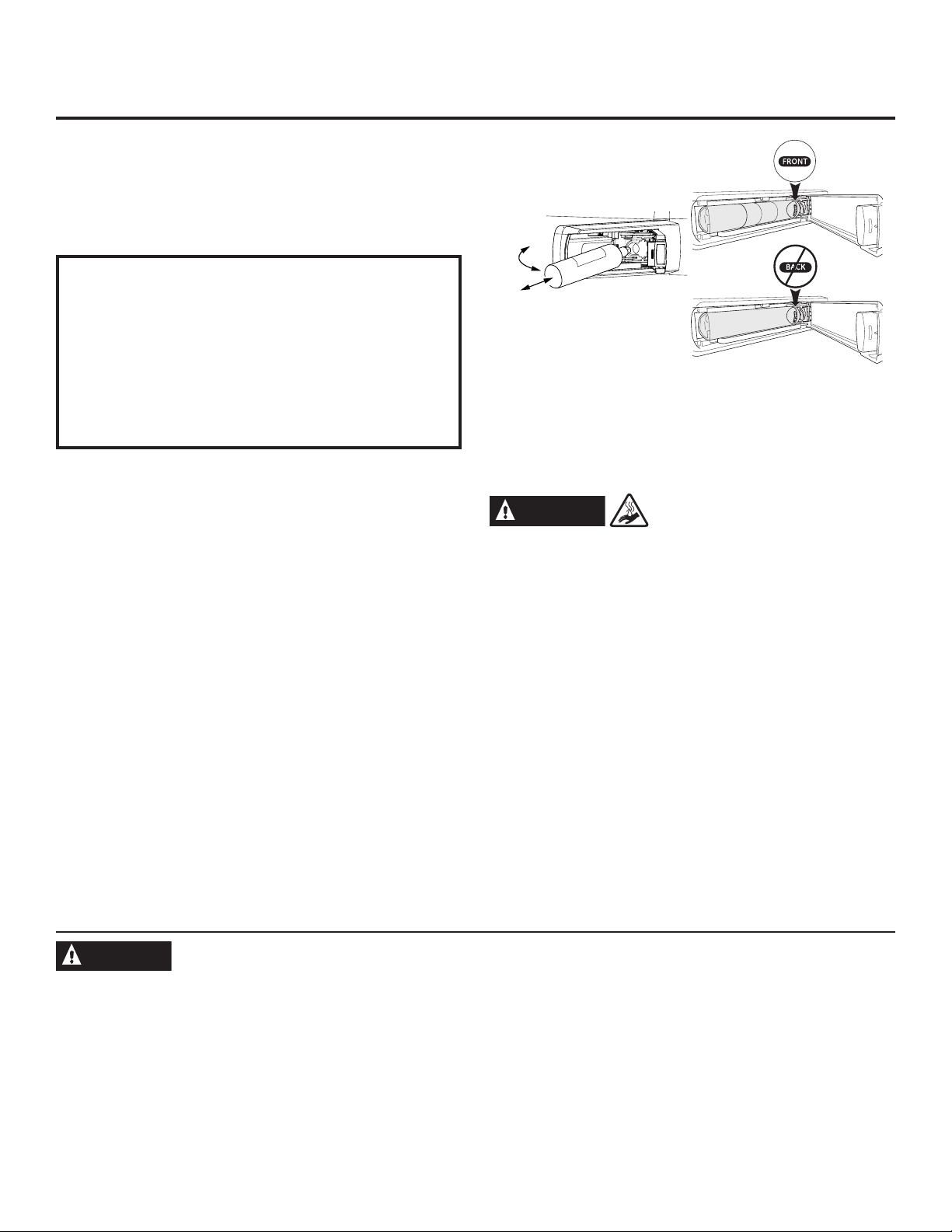
Removing the filter cartridge
To replace the filter, first remove the old cartridge by opening
the filter door and pulling on the bottom of the cartridge to allow
it to swing outward. When the cartridge can no longer swing,
gently pull to unseat it from the cartridge holder. DO NOT TWIST
CARTRIDGE. A small amount of water may drip out.
Installing the Filter Cartridge
1. Align top of filter cartridge with cartridge holder with the word
“FRONT” facing outward then push the cartridge toward
the rear of the unit until it is fully seated. DO NOT TWIST THE
FILTER CARTRIDGE!
2. While continuing to ensure cartridge is fully seated in the
holder, gently swing the filter inward until it is in position. If
filter will not swing easily, check to ensure filter is properly
aligned and fully seated within the cartridge holder. Close the
filter door.
Swing
Push \ Pull
3. Run two gallons of water through the cold water dispenser
(about 5 minutes) to remove air from the system. A newly
installed filter cartridge will cause water to spurt from the
dispenser. Use a large pitcher or sports bottle to catch the
water spray. DO NOT use hands-free auto-fill (some models)
until all air is removed from the system.
4. Reset Filter Status message (non-touch screen models).
WARNING
Use of the hot water dispenser prior to purging air from the
system may result in spurting of hot water and lead to hot water
scalding. Follow the instructions above to purge all air from the
system through the cold water dispenser prior to using the hot
water dispenser.
Note: It is normal for water to appear discolored during the initial
system flush. Water color will return to normal after first few
minutes of dispensing.
Filter Bypass Plug
To reduce the risk of property damage due to water leakage,
you MUST use the filter bypass plug when a replacement filter
cartridge is not available. The dispenser and icemaker will not
operate without either the filter or bypass plug installed. The
bypass plug is installed in the same way as a filter cartridge.
*Select Models Only
Scalding Hazard.*
WARNING
To reduce the risk associated with choking, do not allow children under 3 years of age to have access to small parts
during the installation of this product. The disposable filter cartridge should be replaced every 6 months at the rated capacity,
or sooner if a noticeable reduction in flow rate occurs.
For the maximum benefit of your filtration system, GE recommends the use of GE-branded filters only. Using GE-branded filters
in GE and Hotpoint® refrigerators provides optimal performance and reliability. GE filters meet rigorous industry NSF standards
for safety and quality that are important for products that are filtering your water. GE has not qualified non-GE-branded filters
for use in GE and Hotpoint refrigerators and there is no assurance that non-GE-branded filters meet GE’s standards for quality,
performance and reliability.
If you have questions, or to order additional filter cartridges, visit our website at www.geapplianceparts.com or call GE
Parts and Accessories, 800.626.2002.
Customers in Canada should consult the yellow pages for the nearest Camco Service Center.
12
Page 13
About the fresh food storage options.
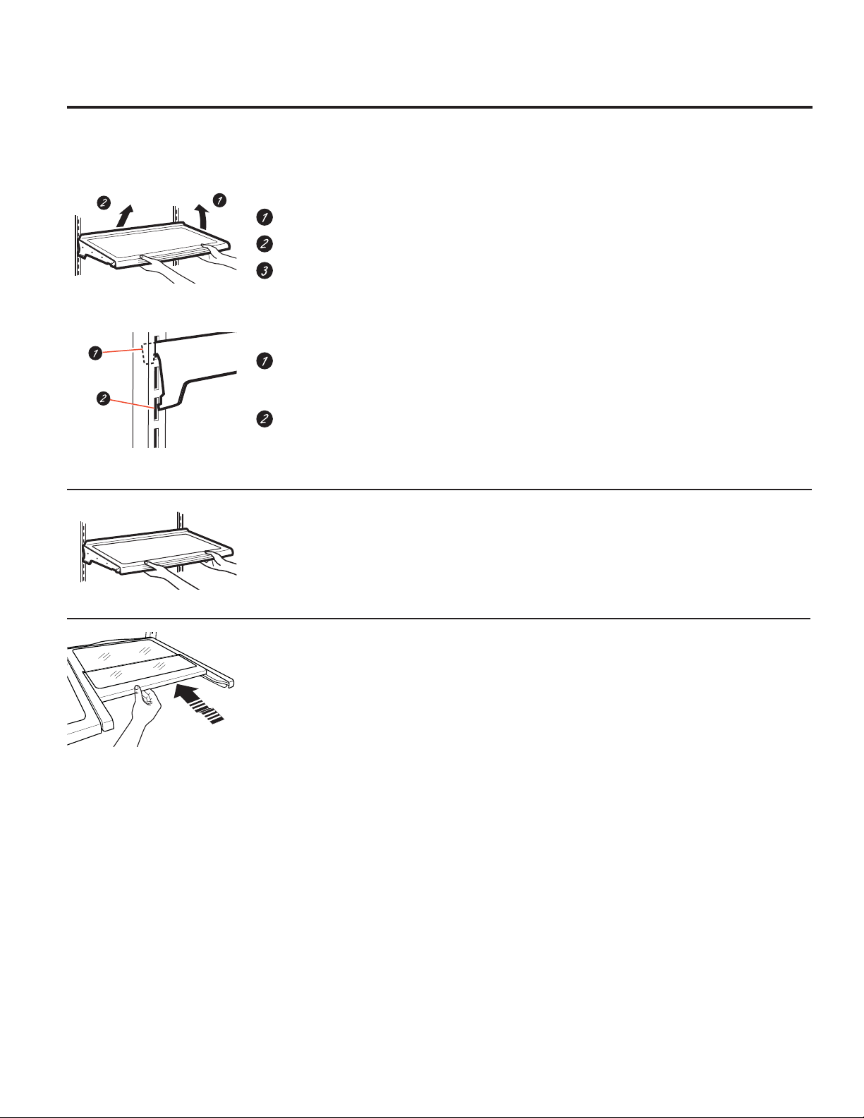
Rearranging the Shelves
Shelves in the refrigerator compartment are adjustable.
To remove:
Remove all items from the shelf.
Tilt the shelf up at the front.
Lift the shelf up at the back and bring the
shelf out.
To replace:
While tilting the shelf up, insert the top hook
at the back of the shelf in a slot on the
track.
Lower the front of the shelf until the bottom
of the shelf locks into place.
Spillproof Shelves
Spillproof shelves have special edges to help
prevent spills from dripping to lower shelves.
Quick Space Shelf *
This shelf splits in half and slides under itself for
storage of tall items on the shelf below.
This shelf can be removed and replaced or
relocated (just like spillproof shelves).
NOTE: The location of the upper Quick Space
Shelf is not adjustable.
*Select Models Only
13
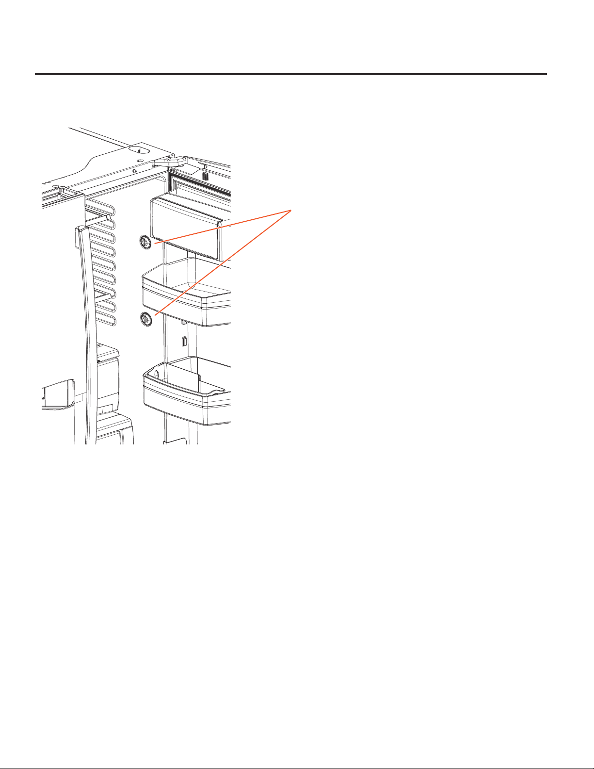
Page 14
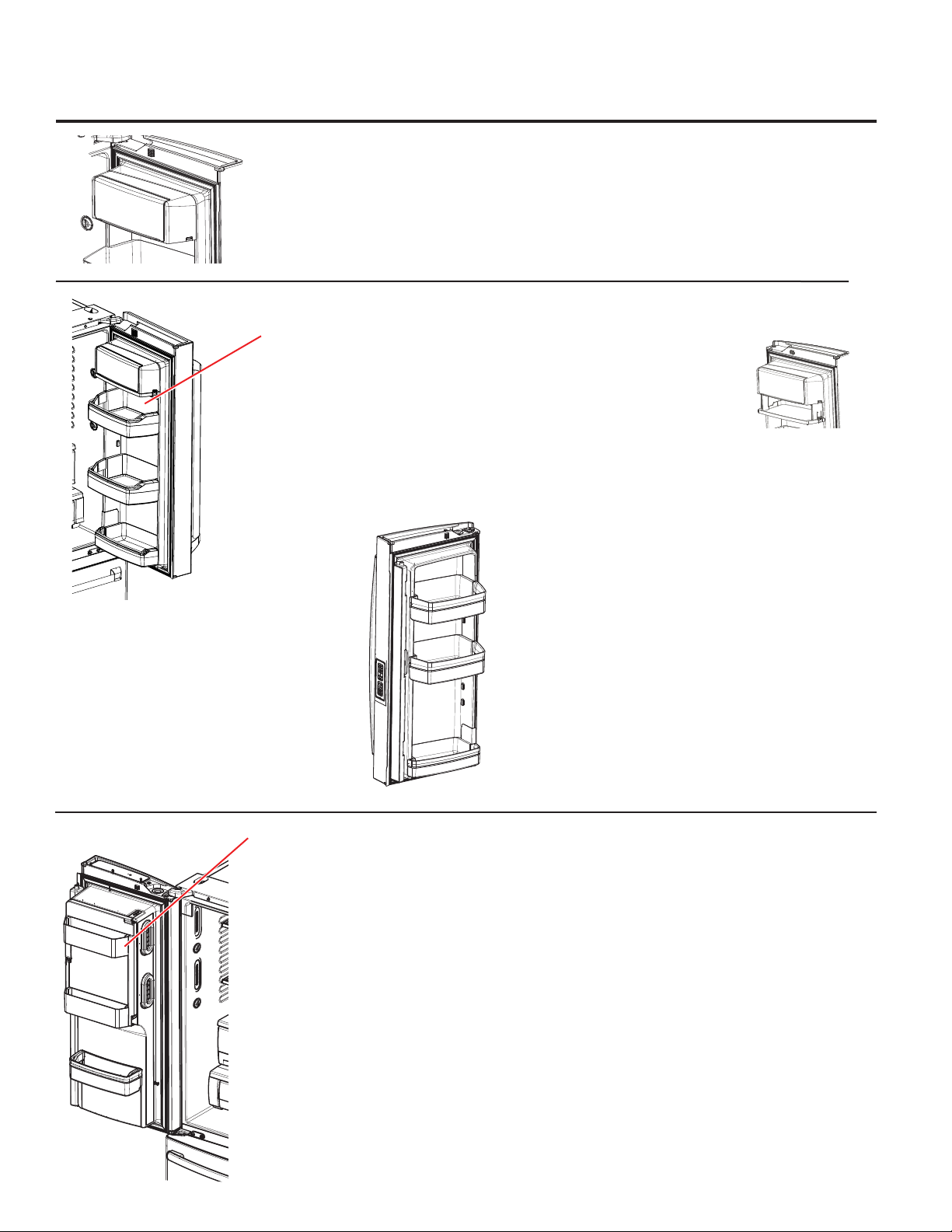
About the fresh food storage options.
Non-Adjustable Dairy Bin*
To remove: Lift the dairy bin straight up,
then pull out.
Adjustable Bins on the Door
Adjustable bins can easily be carried from
refrigerator to work area.
To remove: Lift bin straight up, then pull out.
To replace or relocate: Slide in the bin just
above the molded door supports, and push
down. The bin will lock in place. See page 33.
Non-Dispense Models
(Left Hand Door)
To replace: Engage the bin in the molded door
supports and push down. The bin will lock in
place. See page 33.
Drop down tray *
(tray open)
1. Open right fresh food
door
2. Depress both buttons
on lower sides of bin
and bin will drop down.
3. Reverse to reinstall.
Non-Adjustable Bins on the Door (Dispenser Models - Left Hand Door)
To remove: Lift the bin straight up, then pull out.
To replace: Engage the bin in the molded
supports on the door and push down. It will lock
in place.
The ice maker door bins are not
interchangeable, note the location upon
removal and replace the bin in its proper
location.
*Select Models Only
14
Page 15
About the climate zone and
C
D
temperature controlled drawer. GEAppliances.com
ClimateZone
Keep fruits and vegetables organized in separate
compartments for easy access.
Excess water that may accumulate in the bottom
of the drawers or under the drawers should be
wiped dry.
Fruits Vegetables
Fruits Vegetables
F
C
M
E
AT
ClimateZone
DE
L
I
P
R
O
DU
C
Fruits Vege
E
CHE
ESE
C
IT
R
U
S
SE
L
EC
T
Note: Temperatures indicate the appropriate tem-
peratures for the food and actual temperatures may
vary based on normal operation and other factors
such as door openings and fresh food set point.
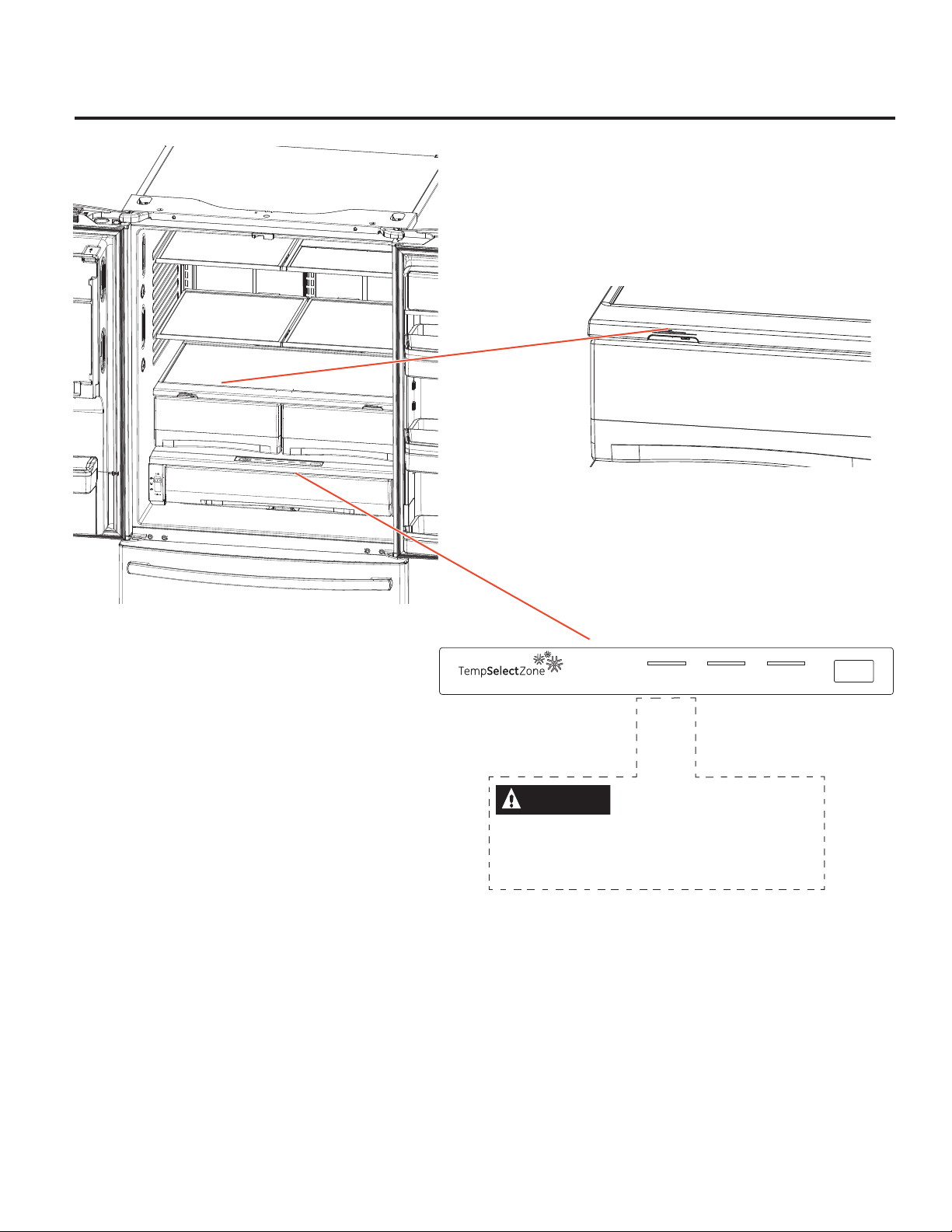
Temperature Controlled Drawer*
The Temperature Controlled Drawer is a
full-width drawer with adjustable temperature
control. This drawer can be used for large
miscellaneous items.
To change setting, press select button.
Meat Beverage Deli
32° 34° 38°
CAUTION
Laceration Hazard.
Do not store glass bottles at this setting. If
they are frozen, they can break and result
in personal injury.
Select
*Select Models Only
15
Page 16
About the climate zone and temperature controlled drawer.
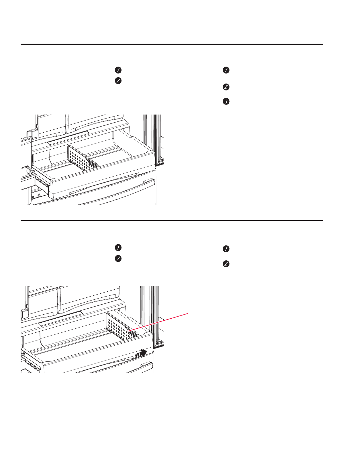
How to Remove and Replace the Adjustable Deli/Produce Drawer
To remove:
Pull the drawer out to the stop position.
Lift the front of the drawer up and out.
To replace:
Pull left and right slides until fully
extended.
Place drawer back in first and rotate
drawer front down to seat on slide.
Push the drawer in to closed position.
How to Remove and Replace Drawer Divider*
To remove:
Pull the drawer out to the stop position.
Raise the front side of the divider
to unhook it from the rear wall of
the drawer.
Divider
To replace:
Hook the back of the divider over the
rear wall of the drawer.
Push the divider down.
*Select Models Only
16
Page 17
About the freezer. GEAppliances.com
Freezer Basket and Drawer
Basket.
Drawer
Ice Bucket *
Non-Adjustable Bin in the Freezer*
To remove: push in plastic tab on either left
or right side
To replace: slide bin into location until it
locks into place.
Basket Removal
To remove, Standard Depth models only:
Open freezer door to the stop position.
Remove freezer door bin by pushing
plastic tab on either left or right side
to release bin hinge pin.
Remove freezer basket by lifting up
the rear of the basket and moving
basket rearward until the front of the
basket can be rotated upward and
out.
Lift it out to remove.
To remove, PYE and PWE models only:
Open fresh food doors.
Open freezer door to the stop position.
Remove freezer basket by lifting up
the rear of the basket and rotate it
upward.
Lift it out to remove.
To replace:
Reverse step 1 thru 4 to replace.
*Select Models Only
17
Page 18
About the automatic ice maker.
A newly installed refrigerator may take 12 to 24 hours to begin making ice.
Ice maker
Feeler Arm
Automatic Ice Maker*
The ice maker will produce seven cubes
per cycle approximately 100–130 cubes
in a 24-hour period, depending on freezer
compartment temperature, room temperature,
number of door openings and other use
conditions.
The ice maker will fill with water when it cools to
15°F (–10°C). A newly installed refrigerator may
take 12 to 24 hours to begin making ice cubes.
If the refrigerator is operated before the water
line connection is made to the unit or if the
water supply to an operating refrigerator is
turned off, make sure that the ice maker is
turned off. Once the water has been connected
to the refrigerator, the ice maker may be turned
on. See the table below for details.
WARNING
You may hear a buzzing sound each time
the ice maker fills with water.
Throw away the first few batches of ice to allow
the water line to clear.
Be sure nothing interferes with the sweep
of the feeler arm.
When the bin fills to the level of the feeler arm,
the ice maker will stop producing ice. It is normal
for several cubes to be joined together.
If ice is not used frequently, old ice cubes will
become cloudy, taste stale and shrink.
NOTE: In homes with lower-than-average water
pressure, you may hear the ice maker cycle
multiple times when making one batch of ice.
To minimize the risk of personal injury, avoid contact with the moving parts of the ejector
mechanism, or with the heating element that releases the cubes. Do not place fingers or
hands on the automatic ice making mechanism while the refrigerator is plugged in.
How to Turn the Ice Maker On/Off
Display Type (See Page 6) Model # How to turn the ice maker on/off
Control Style A PFE28, PYE22P Use the settings menu on the touchscreen
Control Style B GFE28/26, DFE28,
GYE22
Control Style C GNE29, PWE23 Use the “ICE MAKER” button on the control
Use the “ICE MAKER” button on the control
Lift and pull
Ice Box
Door
Ice Bucket and Dispenser*
• Open the ice box door on inside of the left
door.
• Pull up and out on on the ice bucket in
the left hand door to remove it from the
compartment .
• To replace the ice bucket, set it on the
guide brackets and push until the ice
bucket seats properly.
• If bucket cannot be replaced, rotate the ice
bucket fork 1/4 turn clockwise.
18
Extra Ice Storage*
There is additional ice storage in the freezer
compartment drawer.
• Open the freezer drawer.
• The ice bucket is located on the left side of
the upper basket.
• Pull the upper basket forward to remove
the ice bucket.
Freezer
Ice
Bucket
*Select Models Only
Page 19

Care and cleaning of the refrigerator. GEAppliances.com
Cleaning the Outside
The stainless steel panels, door handles and trim.
Do not use appliance wax, polish, bleach, or other products
containing chlorine on stainless steel.
Stainless steel (on some models) can be cleaned with a
commercially available stainless steel cleaner. A spray-on
stainless steel cleaner works best.
Cleaning the Inside
To help prevent odors, leave an open box of baking soda in
the refrigerator and freezer compartments.
Unplug the refrigerator before cleaning.
If this is not practical, wring excess moisture out of sponge or
cloth when cleaning around switches, lights or controls.
Use an appliance wax polish on the inside surface between
the doors.
8VHZDUPZDWHUDQGEDNLQJVRGDVROXWLRQ³DERXWD
tablespoon (15 ml) of baking soda to a quart (1 liter) of water.
This both cleans and neutralizes odors.
Rinse and wipe dry.
Silver-accented plastic parts.
Wash parts with soap or other mild detergents. Wipe clean
with a sponge, damp cloth or paper towel.
Do not use scouring pads, powdered cleaners, bleach or
cleaners containing bleach because these products can
scratch and weaken the paint finish.
Should spill tray need cleaning use lime remover.
CAUTION
Do not clean glass shelves or covers
with warm water when they are cold. Glass shelves and
covers may break if exposed to sudden temperature
changes or impact such as bumping or dropping.
Tempered glass is designed to shatter into many small
pieces if it breaks.
Behind the Refrigerator
Be careful when moving the refrigerator away from the wall. All
types of floor coverings can be damaged, particularly cushioned
coverings and those with embossed surfaces.
Raise the leveling legs located at the bottom front of the
refrigerator.
Preparing for Vacation
For long vacations or absences, remove food and unplug the
refrigerator. Clean the interior with a baking soda solution of
one tablespoon (15 ml) of baking soda to one quart (1 liter) of
water. Leave the doors open.
LCD Models: turn refrigerator off at control (pg 7) .
If the temperature can drop below freezing, have a qualified
service technician drain the water supply system to prevent
serious property damage due to flooding.
Preparing to Move
Secure all loose items such as shelves and drawers by taping
them securely in place to prevent damage.
When using a hand truck to move the refrigerator, do not rest
the front or back of the refrigerator against the hand truck. This
could damage the refrigerator.
Pull the refrigerator straight out and return it to position by
pushing it straight in. Moving the refrigerator in a side direction
may result in damage to the floor covering or refrigerator.
Lower the leveling legs until they touch the floor.
When pushing the refrigerator back, make sure you don’t
roll over the power cord or water supply line.
1) Turn refrigerator off (pg. 7) or unplug the refrigerator.
2) Empty ice bucket
3) Turn water supply off
If you cut the water supply off, turn off the ice maker (pg. 18).
Upon returning from vacation:
1) Replace the water filter.
2) Run 2 gallons of water through the cold water dispenser
(about 5 minutes) to flush the system.
Handle only from the sides of the refrigerator.
Be sure the refrigerator stays in an upright position during
moving.
19
Page 20
Replacing the lights.
Refrigerator Lights (LEDs)
There is LED lighting in fresh food
compartment and on the bottom of
the fresh food doors to light the freezer
compartment.*
An authorized technician will need to
replace the LED light.
If this assembly needs to be replaced, call
GE Service at 1.800.432.2737
in the United States or 1.800.561.3344
in Canada.
*Select Models Only
20
Page 21
Installation
Refrigerator
Instructions
Questions? Call 800.GE.CARES (800.432.2737) or visit our Website at: GEAppliances.com
In Canada, call 1.800.561.3344 or visit our Website at: www.GEAppliances.ca
GE and GE Profile™ models
BEFORE YOU BEGIN
Read these instructions completely and carefully.
WARNING
Built-in style models (model PYE, CYE, GYE, PWE,
CWE, and ZWE)
open. These models must be secured with the anti-tip
floor bracket to prevent tipping forward, which could
result in death or serious injury. Read and follow the entire
installation instructions for installing the anti-tip floor
bracket packed with your refrigerator.
•
IMPORTANT ³ Observe all governing codes and
ordinances. Save these instructions for local inspector’s use.
•
Note to Installer – Be sure to leave these instructions with
the Consumer.
• Note to Consumer – Keep these instructions for future
reference.
• Skill level – Installation of this appliance requires basic
mechanical skills.
• Completion time –
• Proper installation is the responsibility of the installer.
• Product failure due to improper installation is not covered
under the Warranty.
Tip Over Hazard.
are top heavy, especially with any doors
Refrigerator Installation can vary
Water Line Installation 30 minutes
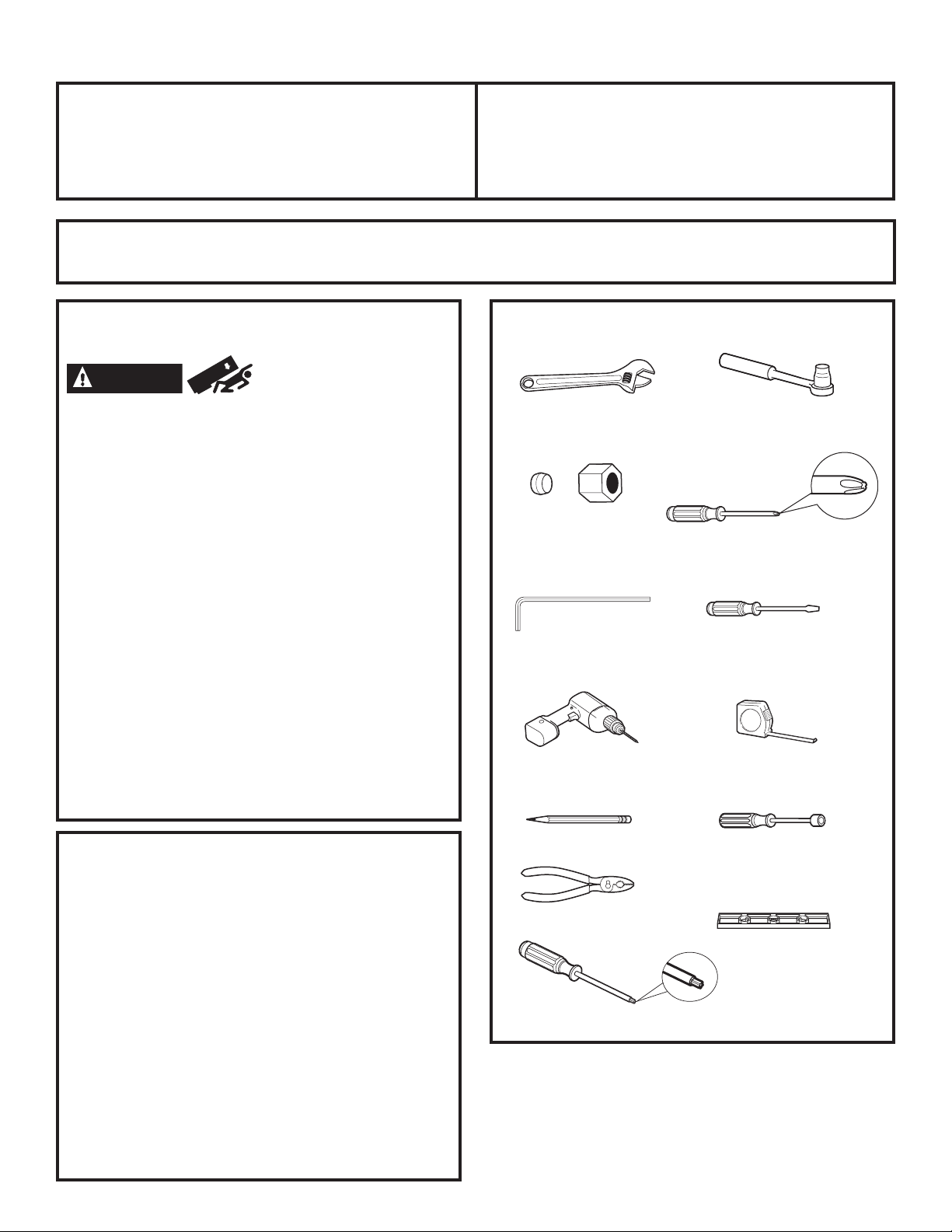
TOOLS YOU MAY NEED
Adjustable Wrench
1/4” Outer Diameter
Compression Nut
and Ferrule (sleeve)
1/8”, 3/32”, 1/4” & 5/32”
Allen Wrenches
1/8” Drill Bit and
Electric or Hand Drill
Ȓµ Socket Ratchet/Driver
Phillips-Head Screwdriver
Flat-Head Screwdriver
Tape Measure
PREPARATION
MOVING THE REFRIGERATOR INDOORS
If the refrigerator will not fit through a doorway,
the refrigerator door and freezer drawer can be removed.
• To remove the refrigerator door, see the Installing
the Refrigerator section.
• To remove the freezer drawer, see the Removing
the Freezer Drawer section.
WATER SUPPLY TO THE ICE MAKER AND DISPENSER
If the refrigerator has an ice maker, it will have to be
connected to a cold water line. A GE water supply kit
(containing tubing, shutoff valve, fittings and instructions)
is available at extra cost from your dealer, by visiting
our website at GEAppliances.com (in Canada at www.
GEAppliances.ca) or from Parts and Accessories, 800.626.2002
(in Canada 1.800.661.1616).
21
Pencil
Pliers
Torx T20, T25
1/4” Nut Driver
5/16” Nut Driver
Level
Page 22
Installation Instructions
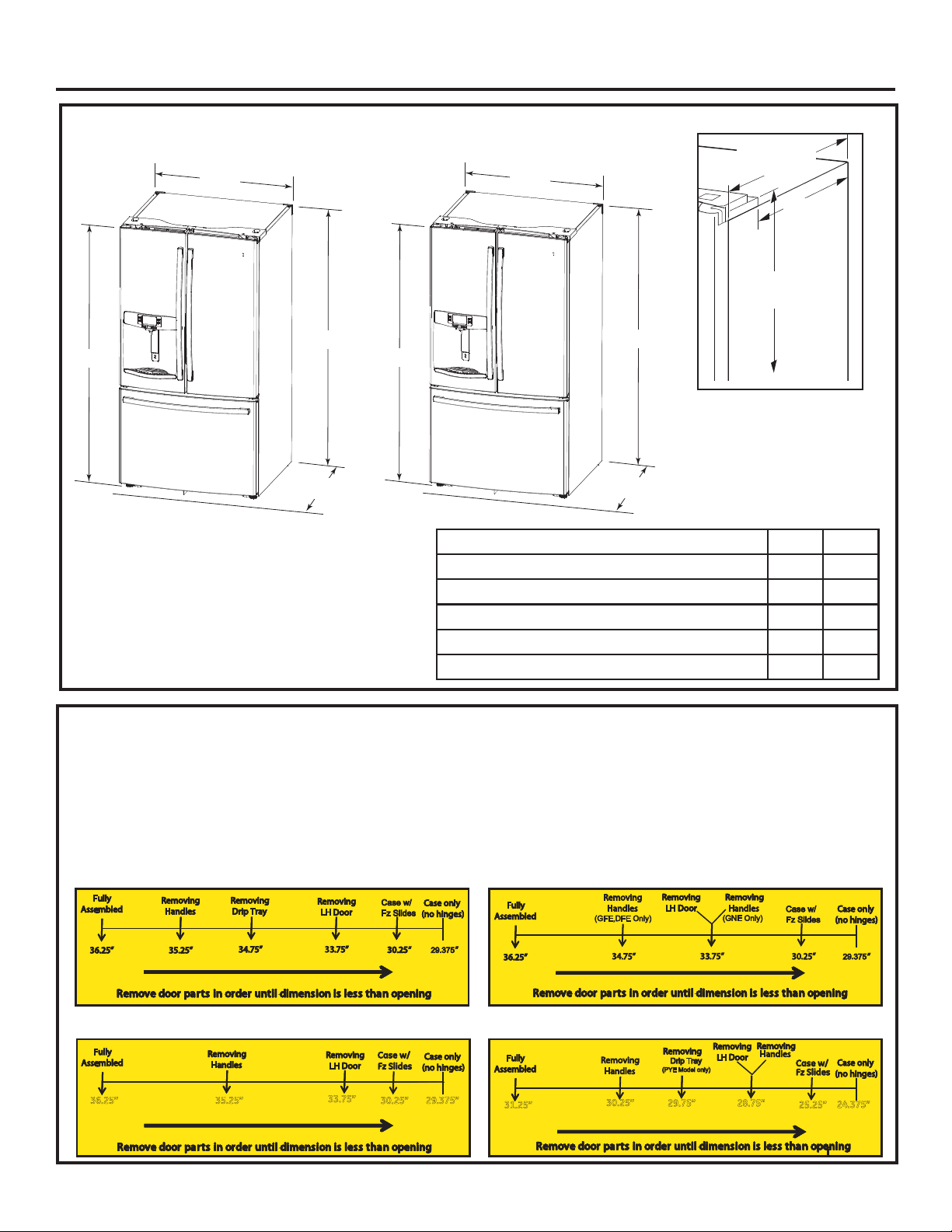
DIMENSIONS
7
ø8
69
”
All measurements are given with leveling leg fully retracted.
Standard Depth (SD) Models OnlyCounter Depth (CD) Models Only
353ø4”
69”
311ø4”
69
7
ø8
”
353ø4”
Overall Height to Top of Hinge Cover
Height to Top of Cabinet
Case Depth without Doors 29
Overall Exterior Case Width
Overall Exterior Depth Doors/Drawers with Handles 36¼” 31¼”
69”
361ø4”
Case Depth w/o
3
24
” SD
ø8
3
” CD
ø8
Doors 29
23 1ø4” SD
18 1ø4” CD
Height from
floor to hinge
cover top 69
7
ø8”
Additional Dimensions
SD CD
7
ø8
69
”69
69” 69”
3
ø8
”24
353ø4”353ø4”
7
ø8
”
3
ø8
Moving THE REFRIGERATOR
• Using the chart below determine if the width of your passageway can accommodate the depth of the refrigerator. Ensure you have clearance
to prevent damage to the refrigerator before safely moving it to the final location.
• If passageways are large enough to accommodate the refrigerator without removing the handles skip to Step 6. Leave tape, film and all
packaging on doors until the refrigerator is in the final location.
• NOTE: Use a padded hand truck or moving straps to move this refrigerator. Place the refrigerator on the hand truck with a side against
the truck. We strongly recommend that two people move and complete this installation.
If your model number starts with PFE (SD)
If your model number starts with CFE (SD)
36.25” 35.25” 29.375”
33.75”
30.25”
If your model number starts with GFE, DFE, GNE (SD)
If your model number starts with CYE, PYE, PWE (CD)
31.25”
30.25”
28.75”29.75”
22
(PWE)
25.25”
24.375”
Page 23
Installation Instructions
INSTALLING THE REFRIGERATOR
REFRIGERATOR LOCATION
• Do not install the refrigerator where the temperature
will go below 60°F (16°C) because it will not run often
enough to maintain proper temperatures.
• Do not install the refrigerator where the temperature
will go above 100°F (37°C) because it will not perform
properly.
• Install it on a floor strong enough to support it fully
loaded.
CLEARANCES
Allow the following clearances for ease of installation,
proper air circulation and plumbing and electrical
connections.
Sides 1/8” (3 mm)
Top 1” (25 mm) Cabinet/Hinge Cover
Back 2” (50 mm)
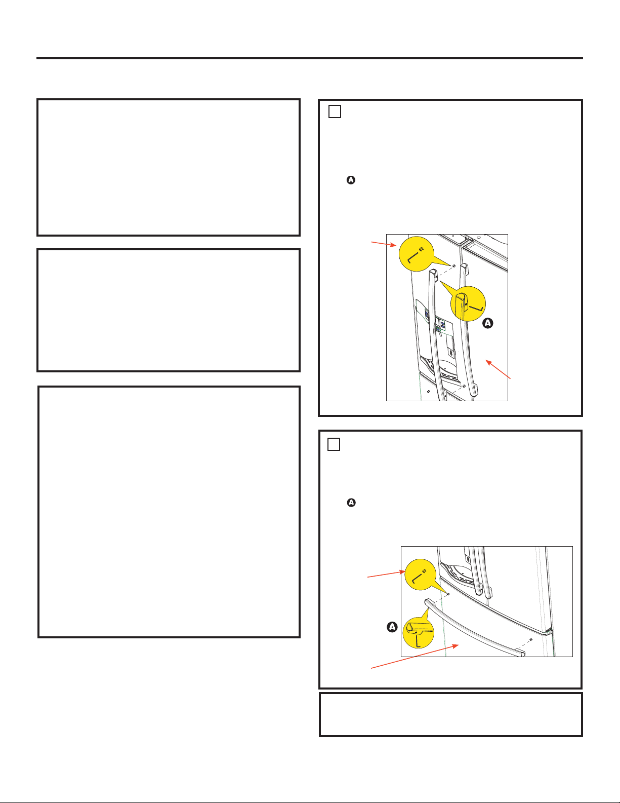
1
REMOVE THE FRESH FOOD
DOOR HANDLE
Handle Design varies based on models, however
Installation is same.
Stainless steel and plastic handles:
Loosen the set screws with the 1/8” Allen wrench
and remove the handle.
NOTE: If the handle mounting fasteners need to be
tightened or removed, use a 1/4” Allen wrench.
Mounting
Fasteners
REMOVING THE REFRIGERATOR DOORS
• IMPORTANT NOTE: This refrigerator is 361/4” deep (311/4”
for CD models). Doors and passageways leading to the
installation location must be at least 36
leave the doors and handles attached to the refrigerator
while transporting it into the installation location. If
1
passageways are less than 36
/4”, the refrigerator doors
and handles can easily be scratched and damaged.
The top cap and doors can be removed to allow the
refrigerator to be safely moved indoors. If passageways
1
are less than 31
/4”, start with Step 1.
• If it is not necessary to remove doors, skip to Step
11. Leave tape and all packaging on doors until the
refrigerator is in the final location.
• NOTE: Use a padded hand truck to move this refrigerator.
Place the refrigerator on the hand truck with a side
against the truck. We strongly recommend that TWO
PEOPLE move and complete this installation.
1
/4” wide in order to
Leave film
on until after
installation
REMO VE T H E FREEZER DOOR HANDLE
2
Handle Design varies based on models, however
Installation is same.
Stainless steel and plastic handles:
Loosen the set screws with the 1/8” Allen wrench and
remove the handle.
NOTE: If the handle mounting fasteners need to be
tightened or removed, use a 1/4” Allen wrench.
Mounting
Fasteners
Leave film
on until after
installation
Reinstall the handles using the same procedure as
removing.
23
Page 24
Installation Instructions
INSTALLING THE REFRIGERATOR (cont.)
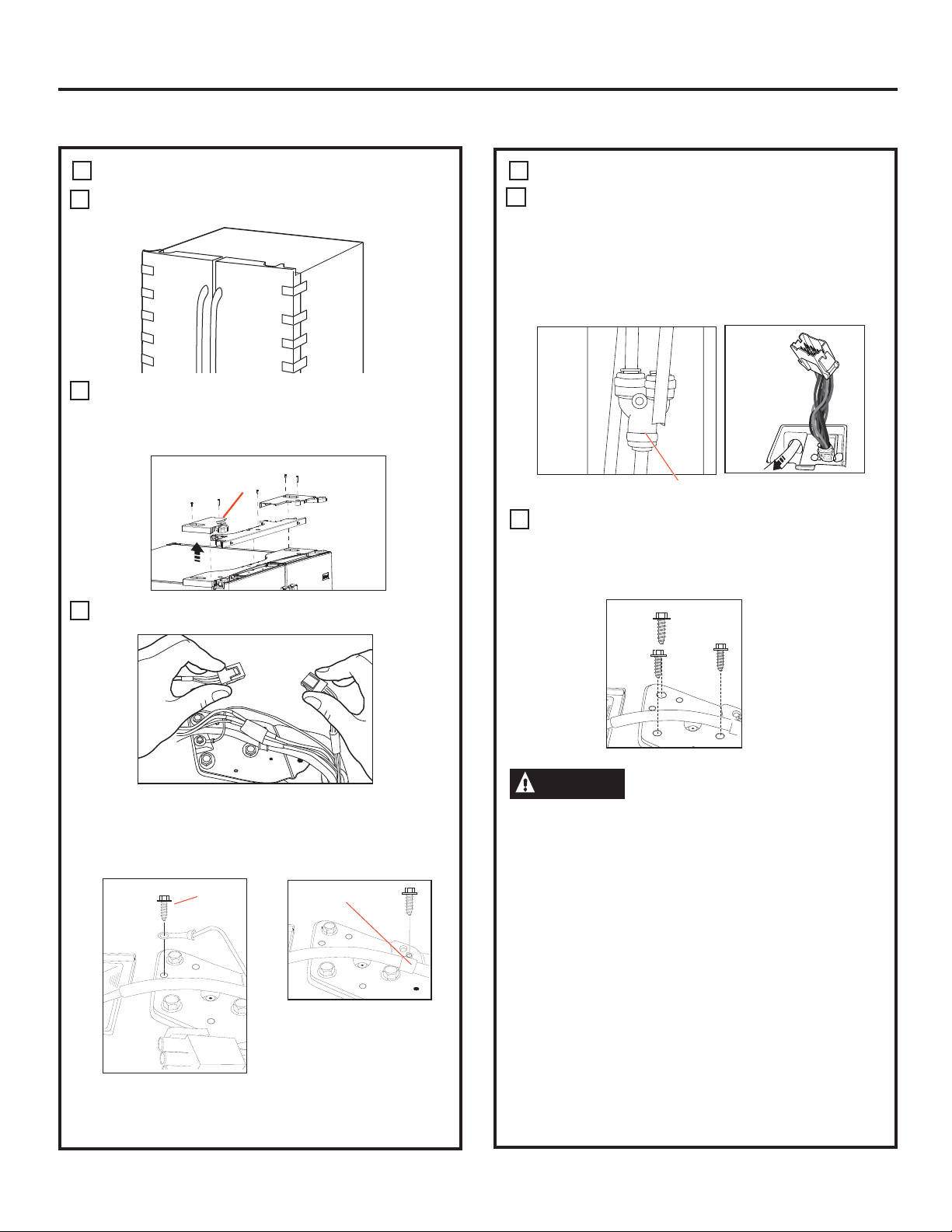
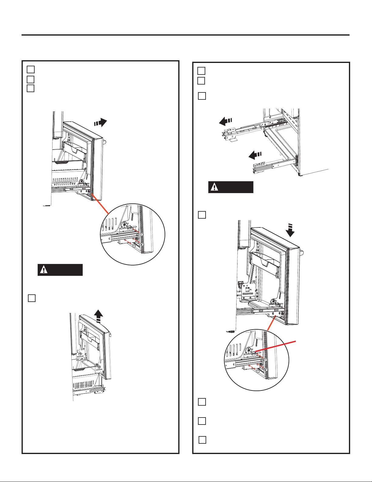
REMOVE THE REFRIGERATOR DOORS
3 3
Securely tape the door shut with masking tape or have
A
a second person support the door.
Start with left-hand door first: Remove the hinge cover
B
on top of the left refrigerator door by removing all hex
screws and pulling it up. Do the same for the
right-hand door and the middle cover.
D
REMOVE THE REFRIGERATOR DOORS (cont)
Disconnect the water line from the back of the unit by
pressing down on the dark grey collar while pulling up
on the water line.
Pull water line through case conduit from the top to
free the line for door removal. The water line is more
than 4’ long and may need to be taped to Door for
accessibility when reinstalling.
Hinge
Cover
C
Disconnect both electrical connectors at the top cover.
Remove the 1/4” hex head screw to disconnect the
ground wire from the hinge.
Remove the 1/4” hex head screw to remove the strain
relief from the water line.
Ground
screw
Strain
Relief
Y or Straight
Connector
E
Using a 3/8” socket ratchet/driver, remove the screws
securing the top hinge to the cabinet,
then lift the hinge straight up to free the hinge pin
from the location in the top of the door.
CAUTION
Single person lift could cause injury. Use assistance
when handling, moving or lifting the refrigerator doors.
Note: when removing door, to prevent damage to door
and electronics, carefully place the door in a proper
location.
Note: The lower door hinge pin and hinge are keyed and
must be matched correctly for the door to self close
properly. Please follow the directions carefully.
Lifting Hazard.
24
Page 25
Installation Instructions
INSTALLING THE REFRIGERATOR (cont.)
REMOVE THE REFRIGERATOR DOORS (cont)
Note: for proper installation later, please follow the next step
carefully.
Remove the tape and keeping the door as
F
straight as possible, open the door to 90º then lift
straight up to remove it.
Lift up & off
center hinge
Open Door to 90°
REMOVE OPPOSITE DOOR
Follow the same procedure on the opposite door. There
are no wires or water lines on the opposite side
4
REMOVE CENTER HINGE (if necessary)
Remove the 3/8ļscrews securing the center hinge to the
cabinet.
Use T20 driver to remove outboard screw
REINSTALLING THE REFRIGERATOR DOORS
5
Reverse steps 1 through 4 to reinstall refrigerator, follow
details below for critical alignments.
Reinstall center hinge first and torque the screws to 65
A
in-lbs. With the LH door at 90º to the front of
the case, lower the refrigerator door onto the center hinge.
Ensure that the door and hinge align correctly.
Rotate doors closed and make sure moveable center sealing
B
portion of the door aligns with the striker. If the door will not
self-close after reinstalling, remove door, turn door upside
down, check alignment mark and arrow; (there is an
alignment mark on the door closure mechanism. It
corresponds to an alignment arrow on the plastic ring. Rotate
door closure mechanism to align mark and arrow, reinstall
door).
Align flats with tab.
Remove
center screw
Loosen Outer
screws
Underside OF
Fresh Food Door
If door cannot be installed at 90° follow steps below:
Install door at 180° to case front.
1.
2. If space limits opening door to less than 180°, then:
a) Remove door, carefully turn door upside down.
b) Check alignment of door closure mechanism shaft on
underside of door. The flats on the shaft should correspond
to alignment tab on plastic ring or mark on bottom end cap.
c) If shaft is not aligned to tab/mark, using 5/32” Allen wrench,
rotate door closure mechanism shaft counterclockwise
for right door and clockwise for left door. Then align
flat with tab/mark.
d) Install the door at 90°.
Securely tape the door shut with masking tape or have a
second person support the door. Reinstall the top hinge and
torque the screws to 65 in-lbs.
Be sure to reinstall the ground wire and strain relief to the top
C
hinge.
Reinstall hinge cover. NOTE: Ensure wires are not pinched or
D
under screw bosses before tightening screws.
25
Page 26
Installation Instructions
INSTALLING THE REFRIGERATOR (cont.)
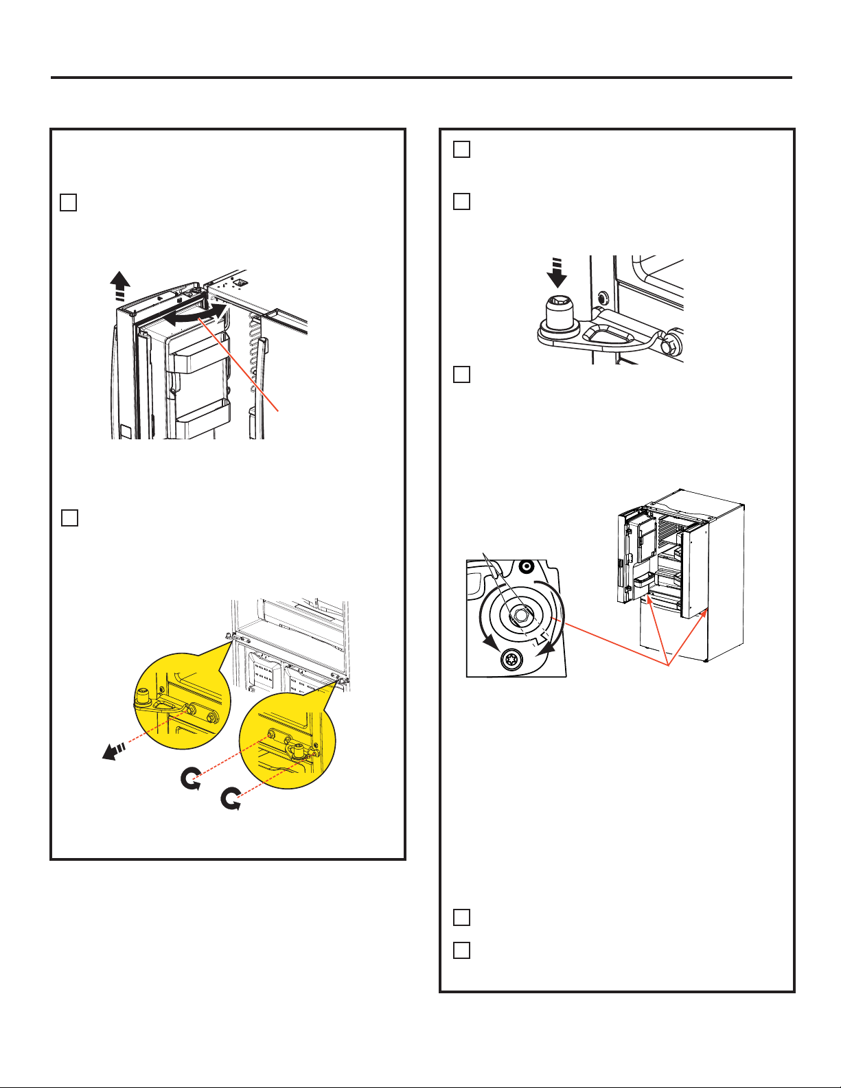
REMOVE THE FREEZER DOOR
6
A
Pull the freezer door open to full extension.
Remove 3 attachment screws, located at the bottom
B
on each side of the freezer door using 3/8” hex socket
driver.
7
A
B
REPLACING THE FREEZER DOOR
Pull the slide Mechanism to full extension using both
hands simultaneously.
Remove the basket resting on the slides.
CAUTION
Freezer door is heavy Use both hands to secure the
door before lifting.
Lift the freezer door to disengage it from the slide
C
mechanism
Lifting Hazard
CAUTION
Freezer door is heavy Use both hands to secure the
door before lifting.
Lift the freezer door and place it on the slide mechanism
C
Lifting Hazard
Align and insert
tab on Freezer
Door Bracket
with slot on
Freezer Slide
Bracket.
The door can safely rest on the bottom. Do not rest the
door on any other surfaces to avoid scratches.
Push the slide mechanism back completely until it self
retracts.
26
Replace the attachment screws and torque the screws
D
to 65 in-lb
For adjusting freezer door gaps, follow the instructions
E
on pg 27.
Replace the basket
F
Page 27
Installation Instructions
INSTALLING THE REFRIGERATOR (cont.)
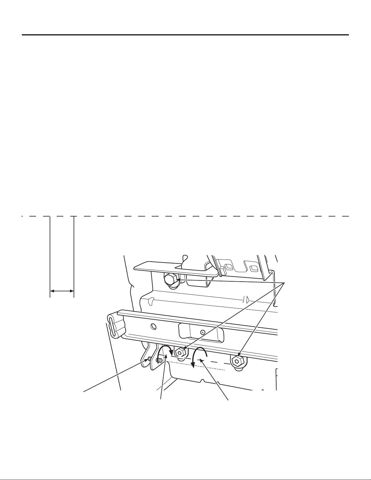
Instructions for adjusting freezer door gaps:
IMPORTANT!
The 6 mounting screws (3 on each side) are NOT interchangeable with the center or top hinge
screws. Drawer screws have flat washer heads, and other screws have lines/ribs on washer heads.
After installation of the freezer door, check for uniform gaps (top and bottom of right and left hand
side) with the template provided.
In the event of excessive gaps use the following steps to adjust the freezer door.
Step 1 - Loosen the 3 screws on each side (right and left) of the freezer door.
Step 2 - Adjust set screw clockwise if gap at the top is too big (see template). Turn the set screw using 3/32” hex
key clockwise by quarter to half a rotation
Step 3 - Adjust set screw counter-clockwise if gap at the bottom is too big (see template). Turn the set screw
using 3/32” hex key counter-clockwise by quarter to half a rotation
Step 4 - Tighten the 3 screws on each side (right and left).
Step 5 - Re-check the gaps using the template and repeat steps 1 to 4 if required and complete with step 5.
Fold here for using template
0.600”
Template for checking gaps.
Gap should be 0.6” or below.
Gabarit pour vérifier les
écarts. L’écart doit être de
0,6 po (1,5 cm) ou moins.
Plantilla para el control de
espacios. El espacio debería
ser de 0.6” o inferior.
Set Screw
Vis d’ajustement
Tornillo del Set
Plier ici pour utiliser le gabarit Dóblelo aquí para usar la plantilla
Step 2
Étape 2
Paso 2
Step 3
Étape 3
Paso 3
Step 1
Étape 1
Paso 1
Step 4
Étape 4
Paso 4
27
Refer to 239D4144P001, Pub No. 31-45474-2
Page 28
Installation Instructions
INSTALLING THE REFRIGERATOR (cont.)
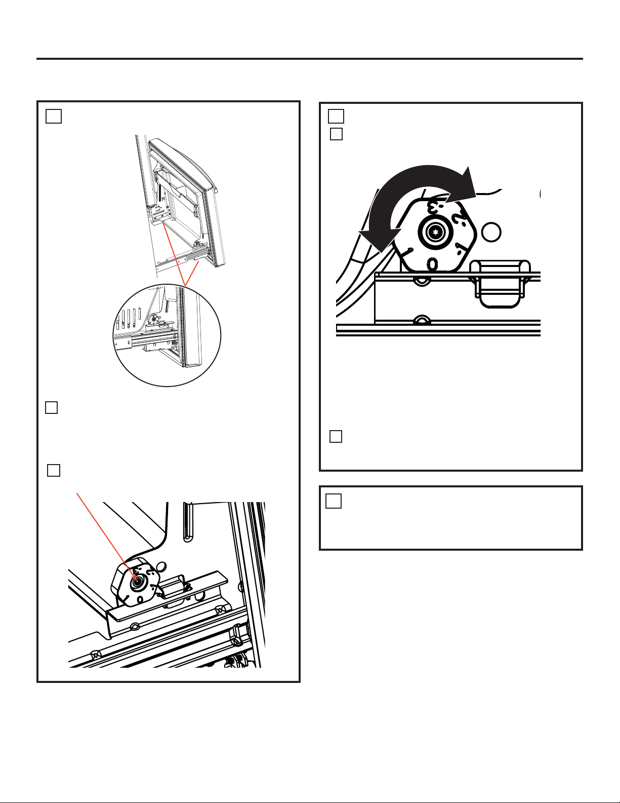
LEVEL THE FREEZER DOOR
8
9
LEVEL THE FREEZER DOOR (cont.)
A
Lift the door on the side requiring adjustment,
rotate the cam to required position.
Locate the height adjuster cam in the freezer
A
door. Slightly loosen the three door attachment
screws on both sides using a 3/8” hex socket
driver.
B
Locate and loosen the cam screw using the
T-27 screw driver.
0 - Initial position
1 - Lift by 0.050”
-1 - Lower by 0.050”
-2 - Lower by 0.100
-3 - Lower by 0.150”
After adjustment tighten the 3 attachment
B
screws using to 65 in-lb.
REMOVE PACKAGING
10
A) Remove all tape, foam and protective
packing from shelves and drawers.
28
Page 29
Installation
Instructions
Anti-Tip Floor Bracket
PYE, CYE, GYE, PWE, CWE,
and ZWE Models Only
WARNING
Built-in style models (model PYE, CYE, GYE, PWE, CWE,
and ZWE) are top heavy, especially with any doors
open. These models must be secured with the anti-tip
floor bracket to prevent tipping forward, which could
result in death or serious injury. Read and follow
the entire installation instructions for installing the
anti-tip floor bracket packed with your refrigerator.
Tip Over Hazard.
NOTE:
If you did not receive an anti-tip bracket with your
purchase, call 1.800.626.8774 to receive one at no
cost. (In Canada, call 1.800.561.3344.)
For installation instructions of the bracket, visit: www.
GEAppliances.com.
(In Canada, www.GEAppliances.ca.)
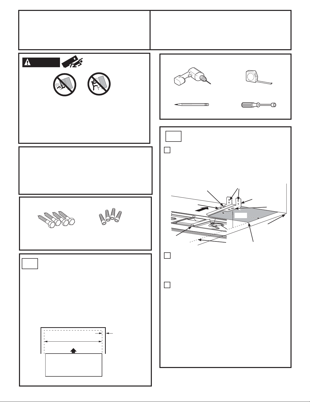
MATERIALS YOU MAY NEED (not included)
TOOLS YOU WILL NEED
1/8” (3 mm) Drill Bit and
Electric or Hand Drill
Pencil
LOCATING THE ANTI-TIP FLOOR
AT-2
Tape measure
5/16” (8 mm) Nut Driver
BRACKET
Place the anti-tip floor bracket locator template
A
(included inside the anti-tip kit) onto the floor
up against the rear wall, within W, and in line
with the desired location of the RH side of the
refrigerator (see Figure 1).
Figure 1 – Installation Overview
Floor – Concrete
(2 Holes)
Floor – Wood
(2 Holes)
2 Wall Holes
Floor Bracket
to Install
RH Holes
Lag Bolts
1/4” (6 mm) x 1-1/2” (38 mm)
Drill Bit Appropriate for Anchors
For Anti-Tip Bracket Mounted on CONCRETE Floors Only
AT-1
MEASURE CABINET OPENING
Anchor Sleeves
1/2” (12 mm) OD
AVAILABLE VS. REFRIGERATOR WIDTH
Measure width of cabinet opening where
refrigerator will be placed, W.
Be sure to account for any countertop overhang,
baseboard thickness and any clearance desired.
Width, W, should not be less than 36”. The
refrigerator will be placed approximately in the
middle of this opening.
Rear Wall
W
REFRIGERATOR
Baseboard
Thickness or
Countertop
Overhang
(Whichever Is
Larger) Plus
Any Desired
Clearance
15 ¼”
Rear RH
Corner of
Base Bracket
on the
Refrigerator
Place the anti-tip floor bracket onto the locator
B
template with its RH floor holes lined up with
the floor holes indicated on the template sheet,
approximately 15 ¼” from the edge of the sheet
or the RH side of the refrigerator.
Hold down in position and use the anti-tip floor
C
bracket as a template for marking the holes
based upon your configuration and type of
construction as shown in Step 3. Mark the hole
locations with a pencil, nail or awl.
NOTE:
• It is REQUIRED to use at least 2 screws to mount
the floor bracket (one on each side of the
anti-tip floor bracket). Both must be into either
the wall or the floor. Figure 2 indicates all the
acceptable mounting configurations for screws.
Identify the screw holes on the anti-tip floor
bracket for your configuration.
RH Side of
Refrigerator
Cabinet Wall
Locator Template
Sheet
Front
RH Side
Refer to 239D1142P001, Pub No. 31-45484-3
29
Page 30
Installation Instructions
LOCATING THE ANTI-TIP FLOOR
AT-2
BRACKET (cont.)
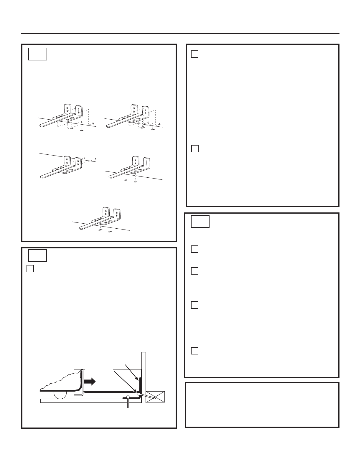
Figure 2 – Acceptable
Screw Placement Locations
Recommended Installation
Minimum Acceptable #1 –
AT-3
WOOD Wall and Floor Construction:
A
– Wood
Wall Plate Stud
Minimum Acceptable #3 –
Concrete Floor
ANTI-TIP BRACKET INSTALLATION
• Drill the appropriate number of 1/8” (3 mm)
pilot holes in the center of each floor bracket
hole being used (a nail or awl may be used if
a drill is not available) AND remove the locator
template from the floor.
• Mount the anti-tip floor bracket by fastening
the 2, or recommended 4, #10-16 hex-head
screws tightly into place as illustrated in
Figure 3.
Figure 3 – Attachment to Wall and Floor
Rear RH
Corner of the
Refrigerator
Must Enter
Metal Stud
Recommended Installation
Minimum Acceptable #2 –
2 Screws
Wood or
Floor
– Concrete
Wood Floor
Floor
Bracket
Wall
Wall
Plate
Stud
CONCRETE Wall and Floor Construction:
B
• Anchors required (not provided):
4 each 1/4” (6 mm) x 1-1/2” (38 mm) lag bolts
4 each 1/2” (12 mm) O.D. sleeve anchors
• Drill the recommended size holes for the
anchors into the concrete at the center of the
holes marked in Step 2.
• Install the sleeve anchors into the drilled
holes. Place the anti-tip floor bracket as
indicated in Step 2. Remove the locator
template from the floor.
• Install the lag bolts through the anti-tip floor
bracket and tighten appropriately.
WOOD Wall and TILE Floor Construction:
C
• For this special case, locate the 2 wall holes
identified in Fig. 1. Drill an angled 1/8” (3 mm)
pilot hole (approx. as shown in Fig. 3) in the
center of each hole.
• Mount the anti-tip floor bracket using the
Minimum Acceptable Installation #1, as
illustrated in Fig. 2.
AT-4
POSITIONING THE REFRIGERATOR
TO ENGAGE THE ANTI-TIP FLOOR
AND BASE BRACKETS
Before pushing the refrigerator into the opening,
A
plug the power cord into the receptacle and
connect waterline (if equipped). Check for leaks.
Locate the refrigerator’s RH side and move back
B
approximately in line with the RH side of the
cabinet opening, W. This should position the
anti-tip floor bracket to engage the anti-tip base
bracket on the refrigerator.
Gently roll the refrigerator back into the cabinet
C
opening until it comes to a complete stop. Check to
see if the refrigerator front lines up with the cabinet
front face. If not, carefully rock the refrigerator
forward and backward until engagement occurs
and you notice that the refrigerator is fully pushed
up against the rear wall.
If Applicable: Adjust the rear (and front) wheel
D
height settings to fully engage the rear anti-tip
brackets, while also aligning the refrigerator
front with the cabinet front face.
NOTE:
If you pull the refrigerator out and away from the wall
for any reason, make sure the anti-tip floor bracket is
engaged when the refrigerator is pushed back against
the rear wall.
30
Refer to 239D1142P001, Pub No. 31-45484-3
Page 31

Installation Instructions
o
u
INSTALLING THE REFRIGERATOR (cont.)
CONNECTING THE REFRIGERATOR
11
TO THE HOUSE WATER LINE
A cold water supply is required for automatic ice maker
operation. If there is not a cold water supply, you will
need to provide one. See Installing the Water Line section.
NOTES:
• Before making the connection to the refrigerator, be
sure the refrigerator power cord is not plugged into the
wall outlet.
• If your refrigerator does not have a water filter, we
recommend installing one if your water supply has
sand or particles that could clog the screen of the
refrigerator’s water valve. Install it in the water line
near the refrigerator. If using GE SmartConnect
Refrigerator Tubing Kit, you will need an additional tube
(WX08X10002) to connect the filter. Do not cut plastic
tube to install filter.
• Before connecting the water line to the house, purge
the house line for at least 2 minutes.
If you are using copper tubing, place a compression nut
A
and ferrule (sleeve) onto the end of the tubing coming
from the house cold water supply.
If you are using the GE SmartConnect
™
tubing, the nuts
are already assembled to the tubing.
™
If you are using copper tubing, insert the end of the
B
tubing into the refrigerator connection, at the back of the
refrigerator, as far as possible. While holding the tubing,
tighten the fitting.
If you are using GE SmartConnect
™
tubing, insert
the molded end of the tubing into the refrigerator
connection, at the back of the refrigerator, and tighten
the compression nut until it is hand tight. Then tighten
one additional turn with a wrench. Over tightening may
cause leaks.
Fasten the tubing into the clamp provided to hold it in
C
position. You may need to pry open the clamp.
1/4”
Compression
Nut
SmartConnect™
Tubing
Ferrule
(sleeve)
Refrigerator
Connection
Tubing Clamp
Bride
Abrazadera del t
1/4“ Tubing
Tuyau de 1/4 p
Tubería de 1/4“
31
Page 32

Installation Instructions
INSTALLING THE REFRIGERATOR (cont.)
TURN ON THE WATER SUPPLY
12
Turn the water on at the shutoff valve (house water
supply) and check for any leaks.
PLUG IN THE REFRIGERATOR
13
15
LEVEL THE REFRIGERATOR DOORS
Remember a level refrigerator is necessary for
getting the doors perfectly even. If you need
help, review the previous section on leveling the
refrigerator.
When
the left
door is
lower than
the right
door.
When
the left
door is
higher than
the right
door.
Adjustment
point
See the grounding information attached to the power
cord.
LEVEL THE REFRIGERATOR
14
The leveling legs have 2 purposes:
1) Leveling legs adjust so the refrigerator is
firmly positioned on the floor and does not
wobble.
2) Leveling legs serve as a stabilizing brake
to hold the refrigerator securely in position
during operation and cleaning. The leveling
legs also prevent the refrigerator from
tipping.
Turn the leveling legs clockwise to raise
A
the refrigerator, counterclockwise to lower it.
If you open the freezer door, you can see
A
the center hinge.
Insert 1/4” Allen wrench into the shaft of the
B
center hinge.
Adjust the height by turning clockwise
C
or counterclockwise. When you turn
counterclockwise, the door will move up.
RAISE
Raise
Flat-Head Screwdriver
NOTICE: To avoid possible property
damage, the leveling legs must be firmly
touching the floor.
32
Page 33

Installation Instructions
Non-Dispense
Models
H
H
J
Refrigerator Assembly Instructions, suggested assembly.
,QVWUXFWLRQVĈDVVHPEODJHGXUpIULJHUDWRUĈDVVHPEODJHVXJJpUHU
Instrucciones de montaje del refrigerador, ensamble sugerido.
G
(Select
models
only)
GE Appliances
General Electric Company
Louisville, KY 40225
GEAppliances.com
To place bins into doors:
Match your bin with the letter shown.
Position the bin hooks over the bin locator
and push forward until inserted fully.
Push bin down until locked into position.
Bin hook
rear each side
Bin locator
each side
33
Refer to 239D4129P002 Pub No. 31-45498
Page 34

Installation Instructions
INSTALLING THE WATER LINE
BEFORE YOU BEGIN
Recommended copper water supply kits are WX8X2,
WX8X3 or WX8X4, depending on the amount of tubing
you need. Approved plastic water supply lines are GE
SmartConnect
WX08X10015 and WX08X10025).
When connecting your refrigerator to a GE Reverse
Osmosis Water System, the only approved installation
is with a GE RVKit. For other reverse osmosis water
systems, follow the manufacturer’s recommendations.
If the water supply to the refrigerator is from
a Reverse Osmosis (RO) Water Filtration System
AND the refrigerator also has a water filter,
use the refrigerator’s filter bypass plug. Using
the refrigerator’s water filtration cartridge in
conjunction with the RO water filter can result in
hollow ice cubes.
This water line installation is not warranted
by the refrigerator or ice maker manufacturer.
Follow these instructions carefully to minimize
the risk of expensive water damage.
Water hammer (water banging in the pipes)
in house plumbing can cause damage to
refrigerator parts and lead to water leakage
or flooding. Call a qualified plumber to correct water
hammer before installing the water supply line to
the refrigerator.
To prevent burns and product damage, do not hook
up the water line to the hot water line.
For PFE27 and PYE23K Models: If the refrigerator is
operated before the water connection is made to
the ice maker, press and hold both the CRUSHED
and CUBED buttons together for 3 seconds to
disengage the ice maker. When the refrigerator has
been connected to the water supply, press and hold
both the CRUSHED and CUBED buttons together for
3 seconds to re-engage the ice maker.
™
Refrigerator Tubing (WX08X10006,
For PFE28 and PYE22P Models: If the refrigerator is
operated before the water connection is made to
the ice maker, see ICE MAKER under SETTINGS menu
of the LCD Operations section and follow the screen
commands to turn the ice maker OFF.
Do not install the ice maker tubing in areas where
temperatures fall below freezing.
When using any electrical device (such as a power
drill) during installation, be sure the device is double
insulated or grounded in a manner to prevent
the hazard of electric shock, or is battery powered.
All installations must be in accordance with local
plumbing code requirements.
WHAT YOU WILL NEED
• Copper or GE SmartConnect™ Refrigerator Tubing
kit, 1/4” outer diameter to connect
the refrigerator to the water supply. If using
copper, be sure both ends of the tubing are
cut square.
To determine how much tubing you need:
measure the distance from the water valve
on the back of the refrigerator to the water supply
pipe. Be sure there is sufficient extra tubing to allow
the refrigerator to move out from the wall after
installation.
GE SmartConnect
available in the following lengths:
6’ (1.8 m) – WX08X10006
15’ (4.6 m) – WX08X10015
25’ (7.6 m) – WX08X10025
™
Refrigerator Tubing Kits are
For Non-LCD Models: If the refrigerator is operated
before the water connection is made to the ice
maker, press and release the ICE MAKER button on
the control panel to disengage the ice maker. When
the refrigerator has been connected to the water
supply, press and release the ICE MAKER button on
the control panel to re-engage the ice maker.
34
Page 35

Installation Instructions
INSTALLING THE WATER LINE (cont.)
WHAT YOU WILL NEED (CONT.)
NOTE: The only GE approved plastic tubing
is that supplied in GE SmartConnect
Tubing kits. Do not use any other plastic water
supply line because the line is under pressure at all
times. Certain types of plastic will crack or rupture
with age and cause water damage to your home.
• A GE water supply kit (containing tubing,
shutoff valve and fittings listed below) is available
at extra cost from your dealer or from Parts
and Accessories, 800.626.2002 (in Canada
1.800.661.1616).
• A cold water supply. The water pressure must be
between 20 and 120 p.s.i. (1.4–8.1 bar).
• Power drill.
• 1/2” or adjustable wrench.
• Straight and Phillips blade screwdriver.
™
Refrigerator
Install the shutoff valve on the nearest frequently
used drinking water line.
1
SHUT OFF THE MAIN WATER SUPPLY
Turn on the nearest faucet long enough to clear
the line of water.
2
CHOOSE THE VALVE LOCATION
Choose a location for the valve that is easily
accessible. It is best to connect into the side
of a vertical water pipe. When it is necessary
to connect into a horizontal water pipe, make
the connection to the top or side, rather than at
the bottom, to avoid drawing off any sediment
from the water pipe.
• Two 1/4” outer diameter compression nuts
DQGIHUUXOHVVOHHYHV³WRFRQQHFWWKHFRSSHU
tubing to the shutoff valve and the refrigerator
water valve.
OR
• If you are using a GE SmartConnect
Refrigerator Tubing kit, the necessary fittings
are preassembled to the tubing.
• If your existing copper water line has a flared
fitting at the end, you will need an adapter
(available at plumbing supply stores) to connect
the water line to the refrigerator OR you can cut
off the flared fitting with a tube cutter and then
use a compression fitting. Do not cut formed end
from GE SmartConnect
• Shutoff valve to connect to the cold water line.
The shutoff valve should have a water inlet with
a minimum inside diameter of 5/32” at the point of
connection to the COLD WATER LINE. Saddle-type
shutoff valves are included in many water supply
kits. Before purchasing, make sure a saddle-type
valve complies with your local plumbing codes.
™
Refrigerator tubing.
™
DRILL THE HOLE FOR THE VALVE
3
Drill a 1/4” hole in the water pipe (even if using
a self-piercing valve), using a sharp bit. Remove
any burrs resulting from drilling the hole in
the pipe.
Take care not to allow water to drain into
the drill.
Failure to drill a 1/4” hole may result in reduced
ice production or smaller cubes.
35
Page 36

Installation Instructions
INSTALLING THE WATER LINE (cont.)
4
FASTEN THE SHUTOFF VALVE
Fasten the shutoff valve to the cold water pipe
with the pipe clamp.
Pipe Clamp
Saddle-Type
Shutoff Valve
NOTE: Commonwealth of Massachusetts
Vertical Cold Water
Pipe
Plumbing Codes 248CMR shall be adhered to.
Saddle valves are illegal and use is not permitted
in Massachusetts. Consult with your licensed
plumber.
TIGHTEN THE PIPE CLAMP
5
Tighten the clamp screws until the sealing
washer begins to swell.
NOTE: Do not over tighten or you may crush
the tubing.
Washer
Pipe Clamp
Inlet End
7
CONNECT THE TUBING TO THE VALVE
Place the compression nut and ferrule (sleeve)
for copper tubing onto the end of the tubing
and connect it to the shutoff valve.
Make sure the tubing is fully inserted into
the valve. Tighten the compression nut securely.
For plastic tubing from a GE SmartConnect
Refrigerator Tubing kit, insert the molded end
of the tubing into the shutoff valve and tighten
compression nut until it is hand tight, then
tighten one additional turn with a wrench. Over
tightening may cause leaks.
Saddle-Type
Shutoff Valve
Packing Nut
Outlet Valve
Ferrule (sleeve)
Compression Nut
SmartConnect™
Tubing
NOTE: Commonwealth of Massachusetts
Plumbing Codes 248CMR shall be adhered to.
Saddle valves are illegal and use is not permitted
in Massachusetts. Consult with your licensed
plumber.
™
Clamp
Screw
ROUTE THE TUBING
6
Route the tubing between the cold water line
and the refrigerator.
Route the tubing through a hole drilled in the
wall or floor (behind the refrigerator or adjacent
base cabinet) as close to the wall as possible.
8
FLUSH OUT THE TUBING
Turn the main water supply on and flush out
the tubing until the water is clear.
Shut the water off at the water valve after about
one quart (1 liter or 2 minutes) of water has been
flushed through the tubing.
To complete the installation of the refrigerator, go back
to Step 11 in Installing the Refrigerator.
36
Page 37

Normal operating conditions.
Newer refrigerators sound different from older refrigerators.
Modern refrigerators have more features and use newer technology.
Do you hear what I hear? These sounds are normal.
HUMMM...
WHOOSH...
The new high efficiency compressor may run faster and longer
than your old refrigerator and you may hear a high-pitched hum
or pulsating sound while it is operating.
You may hear a whooshing sound when the doors close. This is
due to pressure equalizing within the refrigerator.
After dispensing ice, a motor will close the ice chute to keep
warn room air from entering the ice bucket, maintaining ice at a
freezing temperature.
The hum of the motor closing the ice chute is normal, shortly after
dispensing ice.
GEAppliances.com
You may hear the fans spinning at high speeds. This happens
when the refrigerator is first plugged in, when the doors are
opened frequently or when a large amount of food is added to
the refrigerator or freezer compartments. The fans are helping to
maintain the correct temperatures.
The fans change speeds in order to provide optimal cooling and
energy savings.
CLICKS, POPS,
CRACKS and SNAPS
You may hear cracking or popping sounds when the refrigerator
is first plugged in. This happens as the refrigerator cools to the
correct temperature.
Expansion and contraction of cooling coils during and after
defrost can cause a cracking or popping sound.
On models with an ice maker, after an ice making cycle, you may
hear the ice cubes dropping into the ice bucket.
On models with a dispenser, during water dispense, you may
hear the water lines move at initial dispense and after dispenser
button is released.
START UP COOLING
It can take up to 24 hours for the refrigerator and freezer
temperatures to match the display. During that time refrigerator and
freezer door openings should be minimized.
TIPS
Freezer cools first.
Refrigerator compartment cools last; it may take several
hours after the freezer.
Turning off ice maker makes both fresh food and freezer
food cool faster.
WATER SOUNDS
The flow of refrigerant through the cooling coils may make a
gurgling noise like boiling water.
Water dropping on the defrost heater can cause a sizzling,
popping or buzzing sound during the defrost cycle.
A water dripping noise may occur during the defrost cycle as ice
melts from the evaporator and flows into the drain pan.
Closing the door may cause a gurgling sound due to pressure
equalization.
37
Page 38

Before you call for service…
Troubleshooting Tips
Save time and money! Review the charts on the following
pages first and you may not need to call for service.
Problem Possible Causes What to Do
Water filter indicated as installed
incorrectly or a leak is present on LCD
screen.
Water filter indicator light
remains lit after replacing filter
Water filter indicator light is not lit This is normal. This indicator will turn
Handle is loose/handle has a gap. Handle needs adjusting See Attach Fresh Food Handle and
Refrigerator beeping This is door alarm -Turn off or disable with door closed
Not cooling The cooling system is off See About Controls.
Water has poor taste/odor* Water dispenser has not been used
Water in glass is warm* Normal when refrigerator is first
Water dispenser does not work* Water supply line turned off or not
Water spurting from dispenser* Newly installed filter cartridge Run water from the dispenser for 5
Water filter installed backward or is
leaking.
Filter timer has not been reset or filter
is installed backward.
on to tell you that you need to replace
the filter soon.
for a long time
installed
Water dispenser has not been used
for a long time
Water system has drained Allow several hours for replenished
connected
Water filter clogged or filter/bypass
plug not installed
Air may be trapped in the water
system
Water in reservoir is frozen because
the controls are set too cold
Check for leak. If no leak is present,
remove filter/bypass plug, rotate 180°
and reinstall.
Internal Dispense models:
-Press and hold reset button for 3 seconds
External Dispense models:
-Remove filter and rotate 180 degrees
and reinstall.
See About the Water Filter for more
information.
Attach the Freezer Handle sections for
detailed instructions.
-If door open and alarm is sounding, you
can only snooze the alarm
Dispense water, until all water in system
is replenished.
Wait 24 hours for the refrigerator to
completely cool down.
Dispense water, until all water in system
is replenished
supply to chill
See Installing the Water Line
Replace filter cartridge or remove filter
and install bypass plug
Press the dispenser arm for at least 5
minutes.
Set the refrigerator control to a warmer
setting and wait 24 hours. If the water
does not dispense after 24 hours, call for
service
minutes (about 2 gallons)
*Select Models Only
38
Page 39

Before you call for service…
Troubleshooting Tips (cont)
Problem Possible Causes What to Do
No water or ice cube production* Supply line or shutoff valve is clogge Call a plumber
Water filter is clogged Replace filter cartridge or remove filter and
install bypass plug
Filter cartridge not properly installed Remove and reinstall filter cartridge,
being certain that it locks in place.
Ice maker is turned off Check that the ice maker is turned on. See
About the Automatic Ice Maker.
Water is leaking from dispenser* Air may be present in the water line
system, causing water to drip after
being dispensed
Photos not found* Photos not in root directory of USB
Photos not in JPEG format
Camera/PC used with USB cord
AUTO FILL under fill/no fill* Not all containers work with
AUTO FILL
• Container not found
• Unstable container
• Misaligned container
AUTO FILL overfills* Not all containers work with
AUTO FILL
PRECISE FILL will not fill container* Normal, PRECISE FILL requires use of
dispenser paddle
Freezer cooling, fresh food not cooling Normal, when refrigerator first
plugged in or after extended power
outage
Ice dispenser opens after closing
freezer drawer *
Normal The ice dispenser door may open after
Dispense water for at least 5 minutes to
remove air from system
Make sure the photos are in the root directory in your USB
Photos must be in JPEG format
Must use a USB drive
Try different container
See pg. 11
Try different container
For a specific amount of water, select PRE-
CISE FILL to dispense water
Wait 24 hours for temperature in both
compartments to reach selected
temperatures.
closing freezer door to allow access
GEAppliances.com
*Select Models Only
39
Page 40

Before you call for service, review the detailed troubleshooting tips in the Owner’s
SERVICE
manual. If needed, service can be scheduled by visiting us online GEAppliances.
com or calling 800.ge.CARES 800.432.2737
Truth or Myth
Truth or Myth? Answer Explanation
The refrigerator water filter may require replacement
prior to six months
The automatic ice maker in my refrigerator will
produce ice when the refrigerator is plugged in to a
power receptacle.
After the refrigerator has been plugged in and
connected to water, I will immediately have unlimited
chilled water available from the water dispenser.
After water dispenses, a few drops of water are
normal.
I will never see frost inside the freezer compartment. MYTH Frost inside the freezer typically indicates that the door is not properly
When the refrigerator is installed, or after replacing the water filter, I must dispense water for five
minutes.
To fill the ice bucket to the maximum capacity, I
should dispense 12 and 18 hours after installation.
I can use the water filter bypass plug to determine if
the filter requires replacement.
The top of the refrigerator doors will always be
aligned.
Refrigerator door handles can be easily tightened. TRUE If door handles are loose or have a gap, the handle can be adjusted using
There may be odor and taste problems with your ice. TRUE After starting the ice maker throw away 24 hours of ice production to
I can make fine adjustments to the fresh food doors
to align them.
Door handles should always be removed for
installation.
TRUE The water filter indicator will indicate the need to replace the water
filter every six months or 170 gallons of water dispensed (select models
only). Water quality varies from city to city. If water flow from the
dispenser slows, or ice production decreases, the water filter should be
replaced, even though the filter indicator may not indicate the need for
replacement.
MYTH The refrigerator must be connected to water, and the ice maker must be
turned on. Make sure the ice maker is turned on, only after the water line
is connected and water is turned on. The ice maker can be turned on/
off from the controls and ensure the ice maker is on, as indicated on the
refrigerator control panel. See About the Automatic Ice Maker.
MYTH The water dispenser tank located inside the refrigerator stores water
for dispensing. The water in this tank requires 24 hours to chill after
installation. High usage conditions will not allow time for the water to
chill.
TRUE A few drops of water may fall from the dispenser, after the dispenser
paddle has been released. To minimize the drops, remove the glass
slowly from the dispenser.
sealed, or has been left open. If frost is found, clear the frost using a
plastic spatula and towel, then check to ensure that no food packages
or containers are preventing the freezer door from closing. Check the
refrigerator control panel to ensure the door alarm is on.
TRUE
TRUE Dispensing 3-4 cubes 12 hours and 18 hours after installation, allows ice
TRUE Decrease in flow from the water dispenser, or decreased ice production,
MYTH Several things can affect the fresh food door alignment, including the
TRUE If the fresh food doors are not aligned, use a 1/4” Allen wrench to adjust
MYTH Check chart on reverse side of this instruction. If the doors must be
A newly installed refrigerator or water filter contains air in the water lines.
Press the dispenser paddle and dispense cold water for at least 5 minutes
to remove air from the water line, and flush the filter.
to disperse within the ice bucket, which in turns calls on the ice maker to
produce additional ice. Normal ice production = 100 cubes in 24 hours.
may indicate the need to replace the water filter. Install the water filter
bypass plug (provided with the refrigerator), and check flow from the
dispenser. If water flow returns to normal with the bypass plug in place,
replace the water filter.
floor the refrigerator is installed on and loading of doors. If the top of
the fresh food doors are not aligned, use a 1/4” allen wrench to adjust
the right/left hand door. The adjustment screw is located on the bottom
right or left hand side of the door; open the freezer door to access the
screw. On some models, the left hand fresh food door may be raised using
spacers. Call 800-GECARES to obtain the spacers.
a 1/8” allen wrench, on set screws located on the ends of the handles.
avoid odor and taste problems.
the right hand door. The adjustment screw is located on the bottom of the
right door. Open the freezer door to access. The left hand fresh food door
may be raised using spacers. Call 800-GECARES to obtain the spacers.
removed do not remove the handles, or if the refrigerator will fit easily
through the passage way opening. Adjust handles that are loose or have
a gap, by adjusting 1/8” set screws on either end of handles.
40
Page 41

Before you call for service, review the detailed troubleshooting tips in the Owner’s
SERVICE
manual. If needed, service can be scheduled by visiting us online GEAppliances.
com or calling 800.ge.CARES 800.432.2737
Truth or Myth (cont.)
Truth or Myth? Answer Explanation
Door removal is always required for installation. MYTH Check chart on reverse side of this instruction. Doors should only be
removed when necessary to prevent damage from passage way or
access to final location.
Refrigerator doors that won’t close after installation,
can be adjusted to close properly.
There is an adjustment to rear wheels. MYTH Front leveling legs are adjustable and should be used to balance the
Check for leaks after all water connections are made. TRUE While purging the air from the water system, check all water line
My LCD display will always be on when I plug the
power cord in at installation.
Any packaging residue can be cleaned off the
refrigerator using any cleaner.
TRUE Door mechanism works best if installed at 90°+. If installed at 180°,
remove the door from the mid hinge, and swing the door 180° before
reinstalling. See Reinstalling the Refrigerator Doors.
refrigerator. Leveling legs are used to make initial fresh food door
adjustment .
connections for leaks. Check the connection to the household water
supply at back of refrigerator, and door water line connect.
MYTH If the refrigerator has been stored in a cold environment, the LCD may
be slow to give a proper display. Give the refrigerator enough time to
warm up, and the display should be okay.
MYTH Do not use wax, polish, bleach, or other products containing chlorine
on Stainless Steel panels, door handles and trim. Check this instruction
under “Cleaning the Outside” for full details.
41
Page 42

Refrigerator Warranty.
For US Customers, all warranty service provided by our Factory Service
Centers, or an authorized Customer Care
®
technician. To schedule
service, visit us online at GEAppliances.com, or call 800.GE.CARES
(800.432.2737). Please have serial number and model number available
when calling for service.
In Canada, call 800.561.3344.
Staple your receipt here.
Proof of the original
purchase date is needed
to obtain service under the
warranty.
Servicing your refrigerator may require the use of the onboard data port for diagnostics. This gives a GE
Factory Service technician the ability to quickly diagnose any issues with your appliance and helps GE
improve its products by providing GE with information on your appliance. If you do not want your appliance
data to be sent to GE, please advise your technician NOT submit the data to GE at the time of service.
For the Period of: GE Will Replace
One Year
From the date of the original
purchase
Thirty Days
(Water filter, if included)
From the original purchase
date of the refrigerator
GE PROFILE ™ MODELS ONLY
Five Years
From the date of the
purchase
Any part of the refrigerator which fails due to a defect in materials or workmanship.
During the limited one-year warranty, GE will also provide, free of charge, all labor and related
service to replace the defective part.
Any part of the water filter cartridge which fails due to a defect in materials or workmanship. During
this limited thirty-day warranty, GE will also provide, free of charge, a replacement water filter
cartridge.
Any part of the sealed refrigerating system (the compressor , condenser, evaporator an all
connecting tubing) which fails due to a defect in materials or workmanship.
During this limited five-year sealed refrigerating system warranty, GE will also provide, free of
charge, all labor and related service to replace the defective part in the sealed refrigerating system.
What GE Will Not Cover:
■ Service trips to your home to teach you how to use the product.
■ Improper installation, delivery or maintenance.
■ Failure of the product if it is abused, misused, or used for other
than the intended purpose or used commercially.
■ Loss of food due to spoilage.
■ Replacement of house fuses or resetting of circuit breakers.
■ Damage caused after delivery.
■ Replacement of the water filter cartridge, if included, due to
water pressure that is outside the specified operating range or
due to excessive sediment in the water supply.
(;&/86,212),03/,(':$55$17,(6³<RXUVROHDQGH[FOXVLYHUHPHG\LVSURGXFWUHSDLUDVSURYLGHGLQWKLV
Limited Warranty. Any implied warranties, including the implied warranties of merchantability or fitness
for a particular purpose, are limited to one year or the shortest period allowed by law.
For US Customers: This warranty is extended to the original purchaser and any succeeding owner for products
purchased for home use within the USA. If the product is located in an area where service by a GE Authorized
Servicer is not available, you may be responsible for a trip charge or you may be required to bring the product
to an Authorized GE Service location for service. In Alaska, the warranty excludes the cost of shipping or service
calls to your home.
Some states do not allow the exclusion or limitation of incidental or consequential damages. This warranty gives
you specific legal rights, and you may also have other rights which vary from state to state. To know what your
legal rights are, consult your local or state consumer affairs office or your state’s Attorney General.
Warrantor: General Electric Company. Louisville, KY 40225
■ Replacement of the light bulbs, if included, or water filter
cartridge, if included, other than as noted above.
■ Damage to the product caused by accident, fire, floods or acts
of God.
■ Incidental or consequential damage caused by possible defects
with this appliance.
■ Product not accessible to provide required service.
■ Damage caused by a non-GE Brand water filter.
For Customers in Canada: This warranty is extended to the original purchaser and any succeeding owner for
products purchased in Canada for home use within Canada. In-home warrant service will be provided in areas
where it is available and deemed reasonable by Mabe to provide.
Warrantor Canada: MC Commercial, Burlington, Ontario, L7R 5B6
42
Page 43

RPWFE Water Filter Cartridge Limited Warranty.
Appliance Service
GE
Appliances
800-GE-CARES
For The Period Of: We Will Replace, At No Charge To You:
Contact us at www.geapplianceparts.com,
or call 800.GE.CARES.
Staple your receipt
here. Proof of the
original purchase
date is needed to
obtain service
under the warranty.
Thirty Days
From the date of the
Any part of the water filter cartridge which fails due to a defect in materials or
workmanship during this limited thirty-day warranty.*
original purchase
What is Not Covered:
~Service trips to your home to teach you how to use the product.
~Improper installation.
~ Failure of the product if it is abused, misused, used for other than the intended
purpose or used commercially.
~Replacement of house fuses or resetting of circuit breakers.
~ Replacement of the water filter cartridge due to water pressure that is outside the
specified operating range or due to excessive sediment in the water supply.
~Damage to the product caused by accident, fire, floods or acts of God.
~ Incidental or consequential damage caused by possible defects with this appliance.
This warranty is extended to the original purchaser and any succeeding owner for products purchased for
home use within the U.S.A. In Alaska, the warranty excludes the cost of shipping or service calls to your home.
Some states do not allow the exclusion or limitation of incidental or consequential damages. This warranty
gives you specific legal rights, and you may also have other rights which vary from state to state. To know
what your legal rights are, consult your local or state consumer affairs office or your state’s Attorney General.
For Purchases Made In Iowa: This form must be signed and dated by the buyer and seller prior to the
consummation of this sale.
This form should be retained on file by the seller for a minimum of two years.
Buyer:
Name
Address
City State Zip
Signature Date
* If your GE part fai ls because of a ma nufacturin g defect with in thirty da ys from the date of original purch ase for use, we will give you a n ew or, at our option , a rebuilt par t without charge.
Return t he defective part to t he parts supplier f rom whom it was pu rchased together wit h a copy of the “proof of purchas e” for the part. If the p art is defective and s hows no signs of a buse,
it will b e exchanged. T he warranty does not cover the fai lure of parts which are d amaged while in your possession, are abused, o r have been ins talled improperly. It do es not cover the co st
of returning the p art to the supplier fro m whom it was purchased n or does it cover t he cost of labor to remove or i nstall it to dia gnose the faul t. It does not cover par ts used in prod ucts in
commercial use e xcept in the case of air conditioning equip ment. In no event shall GE be liable for consequenti al damages. Warrantor : General Elec tric Company
EXCLUSION OF IMPLIED WARRANTIES: Your sole and exclusive remedy is part exchange as provided in this Limited Warranty. Any implied warranties, including the implied warranties of
merchantability or fitness for a particular purpose, are limited to six months or the shortest period allowed by law.
Seller:
Name
Address
City State Zip
Signature Date
GE
Appliances
Appliance Park
Louisville, KY 40225
geapplianceparts.com
© 2014 General Electric Company PC78863
34-8715-2704-9
EPA #070595-MEX-001
43
RPWFE
Page 44

Performance Data Sheet
Model: GE RPWFE
Use Replacement Cartridge RPWFE.
The concentration of the indicated substances in water entering the system was reduced to a concentration less than or equal to the permissible
limit for water leaving the system as specified in NSF/ANSI Standard 42 and Standard 53. System tested and certified by NSF International against
NSF/ANSI Standard 42 and Standard 53 for the reduction of substances listed below.
Capacity 170 Gallons (643.5 Liters). Contaminant Reduction Determined by NSF testing.
Substance Tested
for Reduction Average Influent
Chlorine Taste and Odor 2.0 mg/L 2.0 mg/L ± 10% 97.4% 0.05 mg/L N/A ≥50% J-00102044
Nominal Particulate
Class I, , ≥0.5 to < 1.0 μm 7,633,333 pts/mL At least 10,000 particles/mL 99.0% 71,850 pts/ml N/A ≥85% J-00106249
Asbestos 109 MFL
Atrazine 0.009 mg/L 0.009 mg/L ± 10% 94.4% 0.0005 mg/L 0.003 mg/L N/A J-00102058
Benzene 0.016 mg/L 0.015 mg/L ± 10% 96.4% 0.001 mg/L 0.005 mg/L N/A J-00102065
Carbofuran 0.08 mg/L 0.08 mg/L ± 10% 98.8% 0.001 mg/L 0.04 mg/L N/A J-00102059
Cyst* 104,750 cysts/L Minimum 50,000 cysts/L 99.99% 3 cyst/L N/A ≥99.95% J-00102057
Lead pH @6.5 0.140 mg/L 0.15 mg/L ± 10% 99.3% 0.001 mg/L 0.010 mg/L N/A J-00102052
Lead pH @8.5 0.158 mg/L 0.15 mg/L ± 10% 98.3% 0.002 mg/L 0.010 mg/L N/A J-00102053
Mercury @ pH 6.5 0.006 mg/L 0.006 mg/L ± 10% 91% 0.0003 mg/L 0.002 mg/L N/A J-00102054
Mercury @ pH 8.5 0.006 mg/L 0.006 mg/L ± 10% 88.3%% 0.0007 mg/L 0.002 mg/L N/A J-00104087
Lindane 0.002 mg/L 0.002 mg/L ± 10% 99% 0.00002 mg/L 0.0002 mg/L N/A J-00102063
P-Dichlorobenzene 0.222 mg/L 0.225 mg/L ± 10% 99.8% 0.0005 mg/L 0.075 mg/L N/A J-00102067
Toxaphene 0.015 mg/L 0.015 mg/L ± 10% 93.5% 0.001 mg/L 0.003 mg/L N/A J-00102061
2, 4-D Reduction 0.218 mg/L 0.210 mg/L±10% 99.9% 0.0001 mg/L 0.07 mg/L N/A J-00102064
VOC 0.278 mg/L 0.300 mg/L ± 10% 97.7% 0.0015 mg/L N/A ≥95% J-00102070
*Based o n the use of Cry ptosporidi um parvum oo cysts.
NSF specified
Challenge Concentration
7
10
to 108 fibers/L; fibers
greater than 10μm in length 99.99% <1 MFL N/A ≥99% J-00102069
Avg %
Reduction
Average Product
Water
Concentration
Max Permissible
Product Water
Concentration
NSF Reduction
Requirements
NSF
Test Report
The following pharmaceutical reduction claims have not been certified by NSF International. Claims tested and verified
by independent laboratory:
Max Permissible
Substance
Reduction Average Influent
Atenolol 1088 ng/L N/A 99.5% 5.0 ng/L N/A J-00103221
Fluoxetine 845 ng/L N/A 99.4% 5.0 ng/L N/A J-00103221
Ibuprofen 898 ng/L N/A 98.8% 9.9 ng/L N/A J-00103726
Progesterone 945 ng/L N/A 99.4% 5.5 ng/L N/A J-00103727
Trimethoprim 403 ng/L N/A 99.5% 2.0 ng/L N/A J-00103221
NSF specified
Challenge Concentration
Avg %
Reduction
Average Product Water
Concentration
Product Water
Concentration
NSF
Test Report
Application Guidelines/Water Supply Parameters
Service Flow 0.5 gpm (1.89 lpm)
Water Supply Potable Water
It is essential that the manufacturer’s recommended installation, maintenance and filter replacement requirements be carried out for the product to perform as advertised.
See Installation Manual for Warranty information.
Note: While the testing was performed under standard laboratory conditions,
actual performance may vary.
Replacement Cartridge: RPWFE. For estimated costs of replacement elements
please call 1-800-626-2002 or visit our website at www.geapplianceparts.com.
WARNING
To reduce the risk associated with ingestion of contaminants:
~ Do not use with water that is microbiologically unsafe or of unknown quality
without adequate disinfection before and after the system. Systems certified
for cyst reduction may be used on disinfected water that may contain filterable
cysts. EPA Establishment Number 070595-MEX-001.
NOTICE
To reduce the risk of water leakage or flooding, and to ensure optimal filter
performance:
~Read and follow use instructions before installation and use of this system.
~8]bcP[[PcX^]P]SdbTMUST comply with all state and local plumbing codes.
Water Pressure 25-120 psi (172– 827 kPa)
Water Temperature 33º F - 100º F (0.6º C - 38º C)
~Do not install if water pressure exceeds 120 psi (827 kPa). If your water pressure
exceeds 80 psi, you must install a pressure-limiting valve. Contact a plumbing
professional if you are uncertain how to check your water pressure.
~Do not install where water hammer conditions may occur. If water hammer
conditions exist you must install a water hammer arrester. Contact a plumbing
professional if you are uncertain how to check for this condition.
~Do not install on hot water supply lines. The maximum operating water
temperature of this filter system is 100º F (38º C).
~ Protect filter from freezing. Drain filter when temperatures drop
below 33ºF (0.6ºC).
~2WP]VTcWTSXb_^bPQ[T[cTaRPacaXSVTTeTahbXg\^]cWb^ab^^]TaXUh^d^QbTaeT
a noticeable reduction in water flow rate.
~5PX[daTc^aT_[PRTcWTSXb_^bPQ[T[cTaRPacaXSVTPcaTR^\\T]STSX]cTaeP[b\Ph
lead to reduced filter performance and cracks in the filter housing, causing water
leakage or flooding.
Tested and certified by NSF International
against NSF/ANSI Standard 42 and Standard 53
in model GE RPWF and GE RPWFE for the
reduction of the claims specified on the
REPLACEMENT
performance data sheet.
ELEMENT
RPWFE
44
Page 45

Consignes de sécurité .....46, 47
Consignes d’utilisation
Fonctions ...................48-51
Commandes ...................52, 53
Distributeur* .......................54
Remplissage automatique* .........55
Filtre à eau .........................56
Options de stockage des
produits frais .................57, 58
Zone climatisée & Tiroir à
température contrôlée .......59, 60
Congélateur .......................61
Machine à glaçons automatique ....62
Entretien et nettoyage ............. 63
Remplacement des ampoules ......64
Instructions d’installation
Préparation avant installation
du réfrigérateur ..............65, 66
Installation du réfrigérateur .....67–77
Installation de l’alimentation
en eau ...................... 78-80
Conseils de dépannage ....82, 83
Fonctionnement normal ............81
Entretien - Mythe ou réalité .....84, 85
Assistance à la clientèle
Garantie pour les clients. ...........86
Certificat de garantie du filtre à eau
à cartouche RPWFE ..............87
Données de performance ..........88
Assistance à la clientèle ............90
*Certains modèles seulement
Inscrivez ici les numéros de modèle et de
série :
Modèle #____________________
Numéro de Série # ___________
Vous trouverez ces numéros sur l’étiquette
apposée sur le côté gauche à mi-hauteur
du compartiment de réfrigération.
45
Page 46

IMPORTANTES CONSIGNES DE SÉCURITÉ .
VEUILLEZ LIRE TOUTES LES CONSIGNES AVANT UTILISATION .
SÉCURITÉ
IMPORTANTES CONSIGNES DE SÉCURITÉ VEUILLEZ LIRE TOUTES LES CONSIGNES AVANT UTILISATION
Site Internet d’Électroménagers GE
Pour de plus amples informations sur le fonctionnement de votre réfrigérateur, consultez
le site www.electromenagersge.ca ou composez le 800.561.3344.
CONSIGNES DE SÉCURITÉ POUR LE RÉFRIGÉRATEUR
Ce symbole représente une alerte de sécurité. Ce symbole vous avise de dangers possibles pouvant causer
la mort, des blessures ou autres. Tous les messages de sécurité seront précédés du symbole d’ alerte de
sécurité ainsi que des mots « DANGER », « AVER TISSEMENT » ou « MISE EN GARDE ». Ces messages sont les
suivants :
DANGER
AVERTISSEMENT
MISE EN GARDE
Signale une situation qui présente un danger imminent et qui, si elle n’est pas évitée, entraînera des blessures
graves, voire la mort.
Signale une situation qui présente un danger imminent et qui, si elle n’est pas évitée, peut entraîner des
blessures graves, voire la mort.
Signale une situation qui présente un danger imminent et qui, si elle n’est pas évitée, peut entraîner des
blessures mineures ou graves.
.
IMPORTANTES CONSIGNES DE SÉCURITÉ
AVERTISSEMENT
Ce réfrigérateur doit être correctement installé conformément aux
Consignes d’Installation avant toute utilisation.
Débranchez le réfrigérateur avant tout entretien ou réparation.
REMARQUE : Les réparations doivent être effectuées par un
professionnel qualifié.
Remettez toutes les pièces et panneaux en place avant d’utiliser
l’appareil.
Nous déconseillons fortement l’utilisation d’une rallonge à cause
des risques potentiels dans certaines conditions. Cependant, si
l’utilisation d’un cordon prolongateur est nécessaire, ce dernier doit
obligatoirement être homologué UL (aux USA) ou CSA (au Canada),
à trois brins avec mise à la terre pour appareil électroménager et
doit être équipé d’une fiche et d’une prise femelle avec terre. Les
caractéristiques électriques du cordon prolongateur doivent être
de 15 ampères (minimum) et de 120 volts.
Pour éviter les risques d’asphyxie et d’enfermement pour les
enfants. Démontez les portes du congélateur et du compartiment
de réfrigération avant de le mettre au rebut ou d’interrompre son
utilisation.
Ne stockez pas ou n’utilisez pas d’essence ou d’autres vapeurs et
liquides inflammables à proximité de cet appareil ou de tout autre
appareil électroménager.
L’alimentation électrique du réfrigérateur ne peut pas être
coupée par l’intermédiaire du panneau de commande. Pour
ce faire, il est nécessaire de débrancher le réfrigérateur pour
couper l’alimentation.
Pour réduire le risque d’incendie, d’explosion, de choc électrique ou de blessures
lorsque vous utilisez votre réfrigérateur, veuillez suivre ces consignes de sécurité :
Ne laissez pas les enfants grimper, se mettre debout ou se
suspendre aux poignées de portes dans le réfrigérateur ou aux
clayettes du réfrigérateur. Ils pourraient se blesser gravement.
Si votre réfrigérateur est doté d’une machine à glaçons
automatique, évitez le contact avec les pièces mobiles du
mécanisme éjecteur, ou avec l’élément chauffant qui libère les
glaçons. Ne posez pas les doigts ou les mains sur le mécanisme de
la machine à glaçons automatique pendant que le réfrigérateur est
branché.
Ne nettoyez pas les clayettes ou les couvercles en verre avec de
l’eau tiède quand ceux-ci sont froids. Les clayettes et couvercles
en verre peuvent se casser s’ils sont exposés à des changements
soudains de température ou si vous les cognez ou les faites
tomber. Le verre trempé est conçu pour se briser en petits
morceaux en cas de casse.
Éloignez les doigts des parties du réfrigérateur où l’on peut
facilement se pincer : les espaces entre les portes, et entre les
portes et les placards sont toujours étroits. Soyez prudent lorsque
vous fermez les portes du réfrigérateur en présence d’enfants.
Ne touchez pas les surfaces froides du congélateur lorsque vous
avez les mains humides ou mouillées. La peau risque d’adhérer à
ces surfaces extrêmement froides.
Ne recongelez pas les aliments surgelés qui ont complètement
dégelé.
Utilisez un verre résistant pour prendre des glaçons (sur les
modèles avec distributeur de glaçons).
AVERTISSEMENT
Risque d’explosion.
Conservez les matériaux et vapeurs inflammables tels que l’essence à l’écart de votre réfrigérateur.
Une explosion, un incendie voire la mort pourrait en résulter.
46
Page 47

IMPORTANTES CONSIGNES DE SÉCURITÉ .
VEUILLEZ LIRE TOUTES LES CONSIGNES AVANT UTILISATION . GEAppliances.ca
SÉCURITÉ (SUITE)
AVERTISSEMENT
Les modèles encastrés (modèles
Risque de basculement
PYE, CYE, GYE, PWE, CWE et ZWE)
sont plus lourds au niveau de leur partie
supérieure, surtout avec les portes ouvertes. Ces modèles doivent être fixés à l’aide du système anti-basculement
par fixation au sol pour éviter que l’appareil ne bascule vers l’avant, ce qui pourrait entraîner des blessures
graves, voire mortelles. Lisez et suivez les instructions d’installation complètes pour l’installation du système antibasculement par fixation au sol livré avec votre réfrigérateur.
BRANCHEMENTS ÉLECTRIQUES
AVERTISSEMENT
Branchez l’appareil dans une prise triple avec terre.
Ne retirez pas la broche de terre.
N’utilisez pas d’adaptateur.
Le non-respect de ces instructions peut entraîner des risques d’incendies, des chocs électriques ou la mort.
Ne coupez pas ou n’enlevez pas, sous aucun prétexte, la troisième broche de mise à la terre du cordon
d’alimentation. Pour des raisons de sécurité, cet appareil doit être correctement mis à la terre.
Le cordon d’alimentation de cet appareil est équipé d’une fiche
à trois broches (pour une mise à la terre) qui s’adapte à la prise
de courant standard à 3 broches (pour une mise à la terre) pour
minimiser les risques de chocs électriques par cet appareil.
Faites vérifier la prise murale et le circuit électrique par un
électricien qualifié pour s’assurer que le système est correctement
mis à la terre.
Dans le cas d’une prise biphasée, l’installateur a la responsabilité
et l’obligation de la remplacer par une prise triphasée
correctement mise à la terre. N’utilisez pas d’adaptateur.
Le réfrigérateur doit toujours être branché à sa propre prise
électrique d’une tension nominale correspondant à celle indiquée
sur sa plaque signalétique.
Risque de choc électrique.
Une alimentation électrique à 115 volts CA, 60 Hz, avec un fusible
de 15 ou 20 ampères et une mise à la terre est nécessaire. Ceci
permet d’obtenir un meilleur rendement et évite de surcharger
les circuits électriques du domicile qui risque d’occasionner un
incendie en surchauffant.
Ne débranchez jamais le réfrigérateur en tirant sur le cordon
d’alimentation. Prenez toujours fermement la fiche en main et
tirez pour la sortir de la prise.
Réparez ou remplacez immédiatement tout cordon électrique usé
ou endommagé. N’utilisez pas un cordon fissuré ou présentant
des dommages dus aux frottements soit sur sa longueur ou aux
extrémités.
Lorsque vous éloignez votre réfrigérateur du mur, faites attention
à ne pas le faire rouler sur le cordon d’alimentation afin de ne pas
l’endommager.
MISE AU REBUT APPROPRIÉE DE VOTRE ANCIEN RÉFRIGÉRATEUR
AVERTISSEMENT
Démontez les portes du compartiment de réfrigération et du compartiment de congélation du
réfrigérateur, avant mettre celui-ci au rebut. Le non-respect de cette recommandation peut entraîner
l’enfermement d’un enfant qui peut entraîner la mort ou des lésions cérébrales.
IMPORTANT:
Un enfant risque de suffoquer ou d’y être emprisonné.
Les enfants pris au piège ou morts d’asphyxie sont toujours
d’actualité. Les réfrigérateurs jetés ou abandonnés restent
dangereux même si vous ne les laissez au rebut que pour «
quelques jours ». Si vous voulez jeter votre ancien réfrigérateur,
suivez les instructions suivantes pour empêcher les accidents.
Avant de jeter votre ancien réfrigérateur ou
congélateur:
Démontez les portes du compartiment de réfrigération et du
compartiment de congélation.
Leave the shelves in place so that children may not easily
climb inside.
Fluides frigorigènes
Les appareils réfrigérants contiennent des fluides frigorigènes
qui conformément à la législation fédérale doivent être retirés
avant la mise au rebut de l’appareil. Si vous mettez au rebut
un ancien réfrigérateur contenant des fluides frigorigènes,
vérifiez la procédure à suivre auprès de la compagnie
responsable de l’élimination.
LISEZ ET SUIVEZ SOIGNEUSEMENT CES CONSIGNES DE SÉCURITÉ.
CONSERVEZ CES INSTRUCTIONS
47
Page 48

A propos des fonctions.
Machine à glaçons à faible encombrement *
La machine à glaçons et son bac sont situés sur la porte
permettant d’avoir un espace de stockage plus spacieux.
Éclairage à DEL
L’éclairage à DEL est placé dans tout le compartiment
pour éclairer différentes zones du réfrigérateur. Des DEL
sont situées sous la porte du réfrigérateur pour éclairer le
congélateur lorsque celui-ci est ouvert.
Plateau rabattable*
Permet un espace de stockage dans la porte en cas de
besoin. Il se replie lorsqu’il ne sert pas.
Tiroir de pleine largeur à température contrôlée
(sur certains modèles)
Bac à température contrôlée qui peut accueillir les
produits les plus volumineux.
Bac à produits laitiers*
Compartiment séparé pour vos produits.
Machine à glaçons double / bac d’appoint
(sur certains modèles))
Une machine à glace pour chacun des deux
compartiments vous permettra d’avoir une plus grande
réserve de glace sous la main.
*Certains modèles seulement
Clayette QuickSpace™ *
Elle s’utilise comme une clayette normale de pleine
largeur. Elle se glisse vers l’arrière pour stocker des
produits hauts.
Clayettes anti-débordements
Conçues pour empêcher les aliments renversés de couler
et permettre ainsi un nettoyage facile.
Tapis antidérapant*
Doublure qui recueille les renversements, empêche les
contenants de bouger à l’ouverture de la porte et se retire
aisément pour le nettoyage.
Bac amovible à condiments
Bac séparé conçu pour faciliter le retrait et le stockage.
Bac climatisé
Bacs séparés pour le stockage des produits.
Filtre à eau*
Filtre l’eau et l’eau destinée à se transformer en glace.
48
Page 49

A propos des fonctions. *
Bac à glace de porte* *
1. Ouvrez la porte gauche du
compartiment de réfrigération.
2. Tirez le loquet vers le bas pour ouvrir la
porte du bac.
3. A l’aide de la poignée, soulevez le seau
à glace pour libérer les repères au fond
du bac.
4. Pour remettre le seau à glace, placez-le
sur les guides et enfoncez-le jusqu’à ce
qu’il soit correctement en place.
5. Si vous n’arrivez pas à le remettre,
faites tourner la fourche d’1/4 de
tour dans le sens des aiguilles d’une
montre.
Bac rabattable pour les produits
laitiers*
1. Ouvrez la porte droite du compartiment
de réfrigération.
2. Appuyez sur les deux boutons sur les
côtés inférieurs et le bac s’ouvrira.
3. Faites la manœuvre en sens inverse
pour le réinstaller.
Filtre à eau/à glace
Retrait du filtre et du bouchon de
dérivation
Poussez sur l’encoche sur le couvercle et
ouvrez la porte du filtre. Retirez le bouchon du
filtre/de dérivation puis tirez directement vers
l’arrière pour sortir le filtre.
Installation de la cartouche filtrante
Poussez sur l’encoche au bas du couvercle et
ouvrez celui-ci. Soulevez la porte et alignez les
languettes du filtre avec celle du support de
filtre et appuyez sur le filtre pour le positionner
correctement.
GEAppliances.ca
Loquet
Seau à glace
Plateau rabattable
[bac ouvert]
Poussez puis
tirez pour
ouvrir
*Certains modèles seulement
Swing
Pivoter
1
Pousser/Enlever
Push \ Pull
2
49
Page 50

À propos des paramètres de température.
PFE28,PYE22P Control Style A, LCD External Control
Control
Lock
Light
Temperature
Cubed
Water
Express Mode
Crushed
Settings
Precise Fill
Auto Fill
Cubed
GFE28, GFE26, DFE28, GYE22 Control Style B, External Control
Refrigerator
Hold 3 Sec for °F/°C
Recommended: 37 °F
Actual Set
F
Energy Smart
Recommended: 0°F
Freezer
Energy Smart Override
Hold 3 Seconds
Door Alarm
Ice Maker
GNE29, PWE23 Control Style C, Internal Control
Lock Controls
Hold 3 Seconds
Reset Filter
Hold 3 Seconds
REMARQUE: Le réfrigérateur est livré avec un film protecteur sur les commandes de températures. Si le film n’a pas
été retiré pendant l’installation, retirez-le maintenant.
Les commandes de températures sont préréglées en usine à 37°F (3°C) pour le compartiment réfrigérateur et à 0°F
(-18°C) pour le compartiment congélateur. Veuillez attendre 24 heures pour que la température se stabilise au préréglage
recommandé.
Les commandes de températures peuvent afficher les températures SET (fixées) ainsi que les températures réelles à
l’intérieur du réfrigérateur et du congélateur. La température actuelle peut légèrement varier de la température SET (fixée)
suivant les conditions d’utilisation et de fonctionnement.
50
Page 51

À propos des paramètres de température.
Modification de la température pour un style de
contrôle A
Pour modifier la température du réfrigérateur :
Activez par : Bouton de température
Activez par : Sous le mot “réfrigérateur”, utilisez les flèches
pour sélectionner la température désirée. Appuyez sur
TERMINÉ pour retourner au menu ACCEUIL.
Pour changer la température du congélateur :
Accédez par : Bouton de température
Activez par : Sous le mot “congélateur”, utilisez les flèches
pour sélectionner la température désirée.
Appuyez sur TERMINÉ pour retourner au menu ACCEUIL.
Temperature
Temperature
Modification de la température pour un style de contrôle B
Pour changer la température, pressez et relâchez la touche
CONGÉLATEUR ou RÉFRIGÉRATEUR. L’affichage indiquera la
tempéture réglée. Pour changer la température, pressez la
touche CONGÉLATEUR ou RÉFRIGÉRATEUR jusqu’à ce que la
température désirée soit affichée.
Pour désactiver le système de refroidissement, accédez aux
commandes PARAMÈTRES par l’écran d’accueil. Passez à
la page suivante puis touchez REFROIDISSEMENT ACTIVÉ.
Appuyez sur TERMINÉ pour revenir à l’écran d’accueil.
Pour activer le système de refroidissement, accédez aux
commandes PARAMÈTRES par l’écran d’accueil. Passez à la
page suivante puis touchez REFROIDISSEMENT DÉSACTIVÉ.
Appuyez sur TERMINÉ pour revenir à l’écran d’accueil.
Désactiver le système de refroidissement arrête le
refroidissement au réfrigérateur, mais il ne coupe pas le
courant électrique.
Pour DÉSACTIVER le système de refroidissement, maintenez
une pression sur les touches RÉFRIGÉRATEUR et MACHINE
À GLAÇONS simultanément pendant 3 secondes. Une fois
le système de refroidissement désactivé, l’affichage devrait
indiquer DÉSACTIVÉ.
GEAppliances.ca
Changer la temp., pour le type de commande C
L’affichage de la température est situé à l’intérieur de la porte
du réfrigérateur à gauche. Pour changer la température,
appuyez et relâchez la languette RÉFRIGERATEUR ou
CONGÉLATEUR. Le voyant lumineux TEMP. ACTUELLE
sera activé et l’écran affichera la température réelle. Pour
modifier la température, appuyez soit sur RÉFRIGÉRATEUR
ou CONGÉLATEUR jusqu’à ce que la température souhaitée
soit affichée.
REMARQUE : Pour une température optimale, il est recommandé d’éviter de placer la nourriture ou d’autres produits
directement devant les bouches de circulation d’air ou devant la tour de ventilation autour des aliments frais,
empêchant ainsi le flux d’air.
Appuyez sur TERMINÉ pour retourner au menu ACCUEIL.
Pour DÉSACTIVER le système de refroidissement, appuyez
sur la languette RÉFRIGERATEUR ou CONGÉLATEUR pendant
3 seconds. Lorsque le système de refroidissement est
DÉSACTIVÉ l’affichage doit indiquer DÉSACTIVÉ.
Pour ACTIVER le système de refroidissement, appuyez sur
la languette RÉFRIGERATEUR ou CONGÉLATEUR. L’écran
affiche les réglages de température préréglés de 37° pour
un réfrigérateur et 0°F pour un congélateur. Désactiver le
système de refroidissement arrête le refroidissement au
réfrigérateur, mais il ne coupe pas le courant électrique.
51
Page 52

À propos des contrôles - Funciones.
Style de commandes A,
Commandes externes
Control
Lock
Light
Temperature
Cubed
Water
Express Mode
Crushed
Settings
Cubed
PFE29, PYE23P
Precise Fill
Auto Fill
Remplissage automatique mains libres*
Le remplissage automatique mains libres fonctionne avec
des capteurs qui contrôlent le remplissage du bac, distribuant l’eau
filtrée automatiquement sans avoir à être activé manuellement.
Réglage du remplissage précis*
Distribue l’eau filtrée et mesurée de façon précise à l’aide
de la commande manuelle, en onces, tasses, pintes ou litres.
Gestion de la température du réfrigérateur
Ajuster la température du compartiment congélateur.
Gestion de la température du compartiment pour les
aliments frais
Ajuster la température du compartiment pour les aliments frais.
Réglage du TurboFreeze
Activer le TurboFreeze pour une restauration rapide de la
température du congélateur après que la porte ait fréquemment
été ouverte.
MC
Réglage du TurboCoolMC
Activer le TurboCool pour une restauration rapide de la
température du compartiment pour les aliments frais après
que la porte ait fréquemment été ouverte.
Commandes de verrouillage
Appuyer pendant 3 secondes pour verrouiller le distributeur de glace et
d’eau ainsi que tous les boutons de commandes et de température.
Lumière DEL du distributeur
Lumière DEL qui peut être allumée pour éclairer votre distributeur.
Commandes de verrouillage
Vous entendrez un avertissement sonore lorsque la porte du congélateur ou celle du compartiment pour les aliments frais aurait été laissée
Maintenez une pression sur la touche AVERTISSEUR SONORE
ouverte.
DE LA PORTE pour voir défiler les options du volume : FAIBLE, ÉLEVÉ et
DÉSACTIVÉ.
*Certains modèles seulement
Style de commandes B,
PFE27, PYE23K
Commandes externes
Chargement de photos*
Insérez une clé USB pour charger des
photos personnelles à l’écran LCD du
réfrigérateur. L’écran vous guidera
dans le chargement et le visionnement du diaporama.
Assurez-vous que les photos sont
dans le répertoire racine de votre clé
USB.
Réglage de la machine à glaçons
Mettre en marche ou éteindre vos machines à glaçons.
Activation/Désactivation du système de refroidissement
Maintenez une pression sur les touches RÉFRIGÉRATEUR et MACHINE À
GLAÇONS simultanément pendant 3 secondes pour activer ou désactiver le système de refroidissement.
Unités métriques/anglaises
Maintenez une pression sur les touches MACHINE À GLAÇONS et AVERTISSEUR SONORE DE PORTE simultanément pendant 3 secondes pour
basculer entre les unités métriques et anglaises.
Réglages additionnels
• Chargement et suppression de photos
• Diaporama
• Prêt pour connexion à la maison
• Réinstallation du filtre à eau
• Machine à glaçons en marche/éteinte
• Avertisseur sonore de la porte
• Gestion du son
• Système de réfrigération en marche/éteint
• Unités de mesure métriques/anglaises
• Tutoriel vidéo pour le remplissage automatique
Modes additionnels
• Mode Sabbath
Appuyer simultanément pendant trois secondes sur le bouton de
verrouillage et sur celui de la lumière pour activer ou désactiver le
mode Sabbath. Activer le mode Sabbath pour éteindre les lumières
intérieures, le contrôle de la température et les fonctions avancées.
Lorsqu’il sera en mode Sabbath, le compresseur sera alimenté par une
décongélation programmée.
Couverture USB
52
Page 53

À propos des contrôles - Funciones.*
GEAppliances.ca
Style de commandes C,
Commandes internes
Recommended: 37 °F
Recommended: 0°F
Avertisseur sonore de la porte
Vous entendrez un avertissement sonore lorsque la porte du
congélateur ou celle du compartiment pour les aliments frais aurait été
laissée ouverte.
Réinstallation du filtre
Appuyer pendant 3 secondes après avoir replacé le filtre.
Commandes de verrouillage
Appuyer pendant 3 secondes pour verrouiller le distributeur de glace et
d’eau ainsi que tous les boutons de commandes et de température.
Refrigerator
Hold 3 Sec for °F/°C
Actual Set
Energy Smart
Freezer
Energy Smart Override
Hold 3 Seconds
Door Alarm
Ice Maker
Lock Controls
Hold 3 Seconds
Reset Filter
Hold 3 Seconds
GNE29, PWE23
F
Gestion de la température du congélateur
Ajuster la température du compartiment congélateur.
Gestion de la température du réfrigérateur
Ajuster la température du compartiment pour les aliments frais.
Réglage de la machine à glaçons
Mettre en marche ou éteindre vos machines à glaçons.
53
*Certains modèles seulement
Page 54

A propos du distributeur.*
Distributeur d’eau et
de glace
(Consulter la section
sur les paramètres
de température et les
fonctions de contrôle)
Precise
Fill
Auto
ll
Fi
ck
Lo
rol
t
Con
Light
Cubed
ter
a
W
Grille du
distributeur
AVERTISSEMENT
Risque de lacération
N’introduisez jamais les doigts ou tout autre objet dans
l’ouverture de sortie du broyeur de glace. Vous risqueriez
de toucher les lames du broyeur de glace et entraîner des
blessures graves, voire une amputation.
Utilisez un verre robuste lorsque vous prenez les glaçons. Un
verre fragile pourrait se casser et occasionner une blessure.
Si l’eau n’est pas distribuée lorsque le réfrigérateur vient d’être
installé, il y a peut-être de l’air dans le conduit d’eau. Appuyez
sur le bras du distributeur pendant au moins cinq minutes pour
purger l’air contenu dans le conduit d’alimentation en eau et
ainsi remplir ce dernier d’eau. Afin d’éliminer les impuretés du
système, jetez les six premiers verres d’eau.
Pour retirer la grille du distributeur (Type A seulement)
Tirez la grille du distributeur vers vous jusqu’à la butée.
Localisez la languette centrale sur le fond de la grille et
appuyez.
Tirez l’ensemble de la grille du distributeur vers vous..
Soulevez la grille métallique du distributeur de métal par
l’encoche centrale pour la nettoyer.
Pour retirer la grille du distributeur (Type B seulement)
Tirez sur la grille du distributeur.
Pour remettre la grille du distributeur (Type A seulement)
Placez le couvercle de la grille du distributeur sur le dessus de
la clayette de récupération et placez-le sous les deux pattes
en plastique de chaque côté.
Centrez la grille du distributeur et alignez-la à l’aide des guides
centraux.
Poussez jusqu’à ce qu’elle soit bien en place.
Pour remettre la grille du distributeur
Centrez la grille du distributeur et poussez-la jusqu’à ce qu’elle
s’encliquette en place.
Informations importantes concernant votre distributeur
N’ajoutez pas de glaçons provenant des bacs ou de sac à
glaçons au seau de la machine à glaçons de la porte. Ils
peuvent être difficile à piler ou à distribuer.
Évitez de trop remplir les verres de glaçons et d’utiliser des
verres étroits. La glace accumulée peut bloquer le conduit ou
peut geler le volet en position fermée. Si des glaçons bloquent
le conduit, retirer le seau à glace et faites-les passer à l’aide
d’une cuillère en bois.
Ne placez pas de boisson ou d’aliment dans le bac de
la machine à glaçons pour les refroidir rapidement. Les
canettes, bouteilles et paquets alimentaires peuvent bloquer
la machine à glaçons ou la vis sans fin.
Pour utiliser le distributeur d’eau interne*
Le distributeur d’eau est situé sur le mur intérieur gauche du compartiment réfrigérateur.
Pour la distribution d’eau :
Placer le verre contre la cavité.
Appuyer sur le bouton du distributeur
d’eau.
Tenir le verre sous le distributeur
pendant 2 ou 3 secondes après avoir
relâché le bouton du distributeur. L’eau
pourrait continuer à couler après que
le bouton ait été relâché.
*Certains modèles seulement
54
Pour éviter que la glace distribuée ne manque le verre, placez
ce dernier à proximité de l’ouverture du distributeur, mais
sans la toucher.
Il est possible que de la glace pilée soit distribuée
même si vous avez choisi CUBED ICE (glaçons). Cela se
produit de temps à autre lorsque plusieurs glaçons sont
accidentellement acheminés vers le broyeur.
Après distribution de glace pilée, de l’eau peut s’écouler du
conduit.
Parfois, un peu de givre se forme sur le volet du conduit à glace.
Ce phénomène est normal et se produit en général après des
distributions répétées de glace pilée. Le givre va éventuellement
s’évaporer.
Si l’eau ne coule pas lorsque le distributeur est utilisé pour la
première fois, il se pourrait qu’il y ait de l’air dans le système de
conduites d’eau. Appuyez sur le bouton du distributeur pendant
au moins 5 minutes pour permettre à l’air emprisonné de sortir
des conduites et pour permettre à l’eau de les remplir. Il se pourrait que le distributeur émette beaucoup de bruit pendant le processus; ce bruit sera provoqué par la sortie de l’air des conduites
d’eau. Afin de nettoyer les conduites d’eau de toute impureté,
jetez les 6 premiers verres d’eau qui sortiront du distributeur.
Note : Pour éviter l’accumulation d’eau, le distributeur devrait
être essuyé de temps à autre à l’aide d’un chiffon ou d’une
éponge propre.
Page 55

À propos du remplissage automatique.*
Pour utiliser le remplissage automatique mains libres :
• Centrer le récipient dans la cavité du distributeur et retirer la
main du récipient.
• Appuyer sur Remplissage automatique
Pour arrêter le Remplissage automatique
• Appuyer sur Annuler; pour reprendre le remplissage, appuyer
sur Remplissage automatique.
Faits importants à propos du Remplissage automatique
•
Pour obtenir des résultats optimaux, utiliser un récipient
uniforme d’une hauteur de 4 à 8 po. et d’une largeur de 2 à
6 po.
• La forme, la capacité et la fonctionnalité des récipients
mesurant plus de 8 po. de hauteur pourraient varier.
• Le volume des récipients pourrait également varier; si vous
recevez le message d’erreur « Récipient introuvable »,
essayez avec un récipient différent.
• Le remplissage automatique prendra fin automatiquement
après un certain temps.
• Une poignée ou d’autres garnitures sur le rebord du récipient
pourraient entraîner un débordement ou des variations du
volume de remplissage.
• Des éclaboussures pourraient se produire selon la position
du récipient, le débit d’eau, la forme du récipient et la
présence de glaçons
• Nettoyer les capteurs régulièrement à l’aide d’un chiffon
propre et humide, et ne pas vaporiser de liquide ni de
nettoyant directement sur les capteurs.
• Le remplissage automatique fonctionne mieux si la
pression d’eau de la résidence se trouve entre 60 et 100
livres par pouce carré.
Capteurs
GEAppliances.ca
*Certains modèles seulement
55
Page 56

A propos de la cartouche RPWFE du filtre à eau GE®.
Cartouche filtrante à eau
La cartouche filtrante à eau est située sur la paroi gauche de
l’intérieur du compartiment réfrigérateur, dans le haut.
Certains modèles utilisent l’identification par radiofréquence
(IRF) pour détecter les fuites et contrôler l’état du filtre. La
technologie IRF est homologuée par la FCC.
FCCID: ZKJ-EBX1532P001 ICID: 10229A-EBX1532P001
« Cet appareil est conforme aux prescriptions de la partie 15
des règles de la FCC. Le fonctionnement de cet équipement est
assujetti aux deux conditions suivantes : (1) Cet appareil ne doit
pas causer de brouillage préjudiciable; et (2) cet appareil doit
accepter tout brouillage qu’il reçoit, y compris celui pouvant
entraîner un fonctionnement indésirable. »
« Cet appareil est conforme aux normes RSS d’Industrie Canada
relatives aux dispositifs exempts de licence. Le fonctionnement
de cet équipement est assujetti aux deux conditions suivantes
: (1) Cet appareil ne doit pas causer de brouillage; et (2) cet
appareil doit accepter tout brouillage, y compris celui pouvant
entraîner un fonctionnement indésirable. »
À quel moment remplacer la cartouche filtrante
La cartouche filtrante doit être remplacée tous les 6 mois ou
plus tôt si 644 litres (170 gallons) d’eau ont été distribués ou
si le débit d’eau du distributeur ou de la machine à glaçons
diminue.
Modèles à écran tactile : Un message d’état du filtre
apparaîtra à l’écran lorsqu’il faudra remplacer le filtre à eau.
L’état du filtre sera mis à jour dès le remplacement du filtre.
Modèles sans écran tactile : Un témoins lumineux s’allumera
sur l’écran lorsqu’il faudra remplacer le filtre à eau.
Remplacement de la cartouche filtrante
Pour remplacer le filtre, retirer d’abord la cartouche usée en
ouvrant le panneau d’accès du filtre puis tirer sur le bas de
la cartouche pour permettre son pivotement vers l’extérieur.
Lorsque la cartouche ne peut plus pivoter, tirer délicatement
pour la dégager de son support. NE PAS TORDRE LA
CARTOUCHE. Une petite quantité d’eau pourrait s’échapper.
Installation de la cartouche filtrante
1.
Alignez le haut du filtre sur le support de la cartouche et
poussez jusqu’à ce que la cartouche soit engagée à fond. La
cartouche doit être introduite dans son support de façon que
le mot FRONT (Avant) soit orienté vers l’extérieur, puis poussée
fermement en place.
2.
Tout en s’assurant que la cartouche se trouve bien au fond de son
support, pivoter délicatement la cartouche vers l’intérieur jusqu’en
position. Si la cartouche ne pivote pas aisément, s’assurer qu’elle
est correctement alignée et bien à fond dans son support.
NE PAS TORDRE LA CARTOUCHE
!
Swing
Pivoter
1
Push \ Pull
Pivoter/Tirer
2
3. Faites circuler 8 litres (2 gallons) d’eau dans le distributeur
d’eau froide (environ 5 minutes) afin d’évacuer l’air
du système. De l’eau jaillira du distributeur suite à
l’installation d’une nouvelle cartouche. Utiliser une
grande cruche ou une bouteille d’eau pour le sport pour
recueillir le jet d’eau. NE PAS utiliser le distributeur d’eau
chaude tant que l’air n’est pas totalement évacué du
système.
4. Réinitialiser le message d’état du filtre (modèles sans écran
tactile).
AVERTISSEMENT
Risque d’ébouillantement.*
L’utilisation du distributeur d’eau chaude avant l’évacuation
de l’air du système peut provoquer un jaillissement d’eau
très chaude causant des brûlures. Veiller à observer les
instructions ci-dessus pour évacuer la totalité de l’air du
système par le distributeur d’eau froide avant d’utiliser le
distributeur d’eau chaude.
Nota : Il est normal d’apercevoir un changement de la
couleur de l’eau lors de la purge initiale du système. La
couleur de l’eau reviendra à la normale après quelques
minutes d’écoulement.
Bouchon de dérivation du filtre
Pour réduire le risque de dommage à la propriété en raison
de fuites d’eau, vous DEVEZ utiliser un bouchon de dérivation
du filtre lorsqu’une cartouche filtrante de rechange n’est
pas disponible. Le distributeur et la machine à glaçons ne
fonctionneront pas sans que ne soient installés le filtre ou le
bouchon de dérivation. Le bouchon de dérivation s’installe de
la même manière que la cartouche filtrante.
*Certains modèles seulement
“Front”
“Back”
AVERTISSEMENT
Pour réduire le risque d’étouffement pendant l’installation de ce produit, ne pas laisser les petites pièces à la portée des
enfants âgés de moins de 3 ans. La cartouche de filtre jetable doit être remplacée tous les 6 mois, si sa capacité nominale est
atteinte ou si une réduction notable du débit est observée.
Pour les meilleurs résultats de votre système de filtration, GE recommande l’utilisation de filtres de marque GE seulement.
L’utilisation de filtres de marque GE dans les réfrigérateurs GE et Hotpoint® procure les meilleurs rendement et fiabilité.
Les filtres GE satisfont aux rigoureuses normes NSF de l’industrie relatives à la sûreté et la qualité, facteur important pour
les produits qui filtrent votre eau. GE n’a pas évalué le rendement des filtres d’autres marques dans les réfrigérateurs GE et
Hotpoint et il n’existe aucune assurance qu’ils satisferont les normes de qualité et de fiabilité GE.
Pour toute question ou pour commander des cartouches filtrantes de rechange, visitez notre site Web au
www.geappliance.ca, ou composez le 800.661.1616.
Les consommateurs du Canada doivent consulter les pages jaunes pour connaître le centre de service Camco le plus proche.
56
Page 57

A propos du stockage des produits frais. GEAppliances.ca
Réorganisation des clayettes
Les clayettes du réfrigérateur sont réglables.
Pour les retirer :
Retirez tous les aliments de la clayette.
Soulevez l’avant de la clayette.
Soulevez l’arrière de la clayette et sortez-la
du réfrigérateur.
Pour le remettre en place :
Tout en inclinant la clayette, insérez le
crochet supérieur à l’arrière de cette même
clayette dans une fente du rail.
Abaissez l’avant de la clayette jusqu’à ce que
le bas de celle-ci se positionne correctement.
Clayettes anti-déversement
Les clayettes anti-déversement ont des bords
adaptés pour éviter que les déversements ne
s’écoulent sur les clayettes inférieures.
Clayette QuickSpace*
Cette clayette se partage en deux avec
une partie qui s’escamote sous l’autre pour
permettre le stockage des articles de grande
taille posés sur la clayette inférieure.
Cette clayette peut être retirée et remplacée
ou déplacée (tout comme les clayettes antidéversement).
REMARQUE : La partie arrière de la clayette
QuickSpace n’est pas réglable.
57
Page 58

A propos du stockage des produits frais.
Bac à produits laitiers non réglable
Pour le retirer : Tirez le bac à produits laitiers
vers le haut, puis retirez-le.
Bacs de porte réglables
Les bacs réglables peuvent facilement être
transportés du réfrigérateur à votre surface de
travail.
Pour les retirer : Tirez le bac vers le haut, puis
retirez-le.
Pour les remettre ou pour les déplacer :
Engagez le bac dans les supports de porte
moulés et poussez-le vers le bas. Le bac
s’encastrera. (Voir page 76).
Modèles sans distributeur
(Porte gauche)
Pour le remettre en place : Engagez le
bac dans les supports de porte moulés et
poussez-le vers le bas. Le bac s’encastrera. Voir
page 33.
Plateau rabattable*
(bac ouvert)
1. Ouvrez la porte droite du
compartiment de réfrigération.
2. Appuyez sur les deux
boutons sur les côtés inférieurs du bac et
celui-ci s’ouvrira.
3. Faites la manœuvre en sens inverse pour
le réinstaller.
Bacs de porte non réglables - (Modèles avec distributeur - Porte gauche)
Pour les retirer : Tirez le bac vers le haut, puis
retirez-le.
Pour les remettre en place : Engagez le
bac dans les supports de porte moulés et
poussez-le vers le bas. Le bac s’encastrera.
Les bacs de porte de la machine à glaçons
ne sont pas interchangeables, notez leur
emplacement lorsque vous les retirez afin de
les remettre au bon endroit.
*Certains modèles seulement
58
Page 59

C
A propos de la zone climatisée & du tiroir
D
à température contrôlée GEAppliances.ca
Zone climatisée
Conservez les fruits et les légumes dans des
compartiments séparés pour un accès facile.
Essuyez l’eau accumulée dans le fond ou en
dessous des bacs.
Fruits Vegetables
Fruits Vegetables
F
C
ClimateZone
M
E
AT
Fruits Vege
DELI
P
R
O
DU
C
E
CHE
E
SE
C
IT
R
U
S
SE
L
EC
T
Remarque : Les températures indiquent les tem-
pératures appropriées pour la conservation des
aliments, les températures réelles peuvent varier en
fonction de l’utilisation du réfrigérateur et d’autres
facteurs tels que les ouvertures de portes et du
réglage de la température selon les aliments.
Tiroir à température contrôlée *
Le tiroir à température contrôlée est un tiroir
de pleine largeur équipé d’un contrôle de la
température. Ce tiroir peut être utilisé pour les
produits divers de grande taille.
Pour modifier les paramètres, appuyez sur
bouton de sélection.
Meat Beverage Deli
Select
32° 34° 38°
MISE EN GARDE
Risque de lacération.
Ne stockez pas les bouteilles en verre lorsque
cette fonction est sélectionnée. Si de la glace se
forme, les bouteilles peuvent se briser et causer
des blessures corporelles.
*Certains modèles seulement
59
Page 60

A propos de la zone climatisée & du tiroir à température contrôlée
Retrait et remise en place du tiroir à charcuterie/à produits frais réglable
Pour le retirer :
Tirez le tiroir jusqu’à la butée.
Soulevez l’avant du tiroir puis faites le sortir
en tirant.
Pour le remettre en place :
Tirez les glissières gauche et droite jusqu’à
ce qu’elles soient complètement sorties.
Placez l’arrière du tiroir en premier, puis
faites pivoter l’avant du tiroir vers le bas
pour que celui-ci repose sur les glissières.
Poussez le tiroir jusqu’à sa position fermée.
Comment retirer le séparateur du tiroir et le remettre en place*
Pour le retirer :
Tirez le tiroir jusqu’à la butée.
Soulevez le côté avant du séparateur
pour le décrocher de la paroi arrière du
tiroir.
Divider
Pour le remettre en place :
Accrochez l’arrière du séparateur sur la
paroi arrière du tiroir.
Poussez le séparateur vers le bas.
*Certains modèles seulement
60
Page 61

À propos du congélateur. GEAppliances.ca
Panier et tiroir du congélateur
Panier
.
Tiroir
Seau à glaçons *
Bac non réglable dans le congélateur*
Pour le retirer : Enfoncez la languette en
plastique de chaque côté.
Pour le remettre en place : Faites glisser
le bac dans la position souhaitée jusqu’à
encastrement.
Retrait d’un panier
Pour le retirer, modèles à profondeur
standard seulement :
Ouvrez la porte du congélateur jusqu’à la
position d’arrêt.
Retirez le bac de la porte du
congélateur en poussant la languette
de plastique du côté droit ou gauche
afin de libérer l’axe de charnière du
bac.
Retirez le panier du congélateur en le
soulevant à l’arrière et en le déplaçant
vers l’arrière jusqu’à ce que l’avant du
panier puisse pivoté vers le haut et
sorti.
Soulevez-le pour le sortir du congélateur.
Pour le retirer, modèles PYE et PWE
seulement :
Ouvrez les portes de la section
réfrigérateur.
Ouvrez la porte du congélateur jusqu’à la
position d’arrêt.
Retirez le panier du congélateur en le
soulevant à l’arrière et en le faisant
pivoter vers le haut .
Soulevez-le pour le sortir du
congélateur.
Pour le remettre en place :
Procéder en sens inverse pour remettre le
bac en place.
*Certains modèles seulement
61
Page 62

À propos de la machine à glaçons automatique.
Il faut prévoir entre 12 et 24 heures avant qu’un réfrigérateur nouvellement installé commence à produire des glaçons.
AVERTISSEMENT
Machine
à glaçons
Bras de détection
Machine à glaçons automatique *
La machine à glaçons produit sept glaçons par
cycle - environ 100–130 cycles par 24 heures,
selon la température du compartiment de
congélation, la température de la pièce, le nombre
d’ouverture de porte et les autres conditions
d’utilisation.
La machine à glaçons se remplit d’eau lorsque
sa température atteint 15°F (-10°C). Il faut prévoir
entre 12 et 24 heures avant qu’un réfrigérateur
nouvellement installé commence à produire des
glaçons.
Si le réfrigérateur est mis en marche avant
que la machine à glaçons ne soit raccordée à
l’alimentation en eau ou si l’alimentation en eau
du réfrigérateur est fermée, assurez-vous que
la machine à glaçons est éteinte. Une fois que
l’eau a été raccordée au réfrigérateur, la machine
à glaçons peut être mise en marche. Référezvous au tableau ci-dessous pour de plus amples
informations.
Vous entendrez un bourdonnement à chaque fois
que la machine à glaçons se remplit d’eau.
Jetez les premiers bacs de glaçons pour bien
nettoyer le conduit d’eau.
Vérifiez que rien n’interfère avec le déplacement
du bras de détection.
Quand le bac se remplit jusqu’au niveau du bras
de détection, la machine à glaçons s’arrête de
produire des glaçons. Il est normal de trouver des
glaçons qui soient soudés ensemble.
Si vous n’utilisez pas souvent vos glaçons, les
vieux glaçons deviennent opaques, prennent un
mauvais goût et rétrécissent.
REMARQUE : Dans les maisons qui ont une
pression d’eau plus faible que la moyenne,
vous entendrez peut-être la machine à glaçons
recommencer plusieurs fois son cycle pour
produire un lot de glaçons.
Pour minimiser les risques de blessures, évitez le contact avec les pièces mobiles du mécanisme éjecteur, ou avec
l’élément chauffant qui libère les glaçons. Ne posez pas les doigts ou les mains sur le mécanisme de la machine à
glaçons automatique pendant que le réfrigérateur est branché.
Comment allumer ou éteindre la machine à glaçons ?
Type d’affichage (voir page 7)
Style de commandes A PFE28, PYE22P Utiliser le menu de réglages de l’écran tactile.
Style de commandes B GFE28/26, DFE28,
Style de commandes C GNE29, PWE23 Utiliser le bouton « Machine à glaçons » Utiliser le bouton « Machine
Numéro de modèle #
GYE22
Comment allumer ou éteindre la machine à glaçons ?
Utiliser le bouton « Machine à glaçons » Utiliser le bouton « Machine
à glaçons »
à glaçons »
Porte du
bac à
glace
Soulevez et tirez
Seau à glaçons et distributeur*
• Ouvrez la porte du bac à glace à l’intérieur
de la porte de gauche.
• Tirez le seau à glaçons vers le haut dans
la porte de gauche pour le sortir du
compartiment.
• Pour remettre le seau à glace, placez-le sur
les guides et enfoncez-le jusqu’à ce qu’il
soit correctement en place.
• Si vous n’arrivez pas à le remettre, faites
tourner la fourche d’1/4 de tour dans le
sens des aiguilles d’une montre.
Stockage de glace supplémentaire*
Un bac de stockage supplémentaire est fourni
dans le tiroir de congélation.
• Ouvrez le tiroir de congélation.
62
• Le seau à glaçons est situé sur le côté
gauche sous panier supérieur.
• Tirez le panier supérieur vers vous pour
enlever le seau à glaçons.
Seau à
glaçons du
congélateur
*Certains modèles seulement
Page 63

Entretien et nettoyage du réfrigérateur GEAppliances.ca
Nettoyage de l’extérieur
Panneaux, poignées de porte et garniture en acier
inoxydable.
N’utilisez pas de cire pour appareil ménager, de produit
polissant, de javellisant ou de tout autre produit contenant
du chlore sur l’acier inoxydable
L’acier inoxydable peut être nettoyé avec un nettoyant
spécialement formulé pour l’acier inoxydable. Les meilleurs
résultats sont obtenus à l’aide d’un nettoyant pour acier
inoxydable à vaporiser.
Nettoyage de l’intérieur
Pour prévenir les odeurs, laissez ouverte une boîte de
bicarbonate de soude dans les compartiments réfrigérateur
et congélateur.
Débranchez l’appareil avant de le nettoyer.
S’il est trop difficile de débrancher l’appareil, essorez bien
votre chiffon ou votre éponge pour enlever l’excès d’eau
lorsque vous nettoyez autour des interrupteurs, des lampes
ou des commandes. Utilisez une cire pour appareil ménager
sur la surface intérieure entre les portes.
Utilisez une solution d’eau tiède et de bicarbonate de soude
Pièces en plastique argenté.
Lavez ces pièces avec du savon ou un autre détergent doux. Essuyez
ensuite avec une éponge, un linge humide ou de l’essuie-tout.
N’utilisez pas de tampons à récurer, de produits nettoyants en
poudre, de javellisants ou de produits contenant du javellisant
sous peine de rayer la finition et de la rendre moins résistante.
Si vous avez besoin de nettoyer le plateau de collecte des
gouttes, utilisez un produit détartrant.
(environ une cuillère à soupe (15 ml) de bicarbonate de soude
dans un litre d’eau) afin de nettoyer tout en neutralisant les
odeurs. Rincez et séchez.
MISE EN GARDE
couvercles en verre avec de l’eau tiède quand ceux-ci
sont froids. Les clayettes et couvercles en verre peuvent
se casser s’ils sont exposés à des changements soudains
de température ou si vous les cognez ou les faites
tomber. Le verre trempé est conçu pour se briser en petits
morceaux en cas de casse.
Ne nettoyez pas les clayettes ou les
Derrière le réfrigérateur
Soyez prudent lorsque vous éloignez votre réfrigérateur
du mur. Tous les types de revêtements de sol peuvent être
endommagés, en particulier les revêtements matelassés et ceux
dont la surface est gaufrée.
Relevez les pieds de mise à niveau situés sur la partie inférieure
avant du réfrigérateur.
Tirez le réfrigérateur en ligne droite et lorsque vous le
remettez en place, poussez-le vers le mur en ligne droite.
Départ en vacances
Encas d’absences ou de vacances prolongées, retirez tous les
aliments du réfrigérateur et débranchez-le. Nettoyez l’intérieur
avec une solution de bicarbonate de soude (environ une cuillère
à soupe (15 ml) de bicarbonate de soude dans un litre d’eau).
Laissez les portes ouvertes.
Modèles avec affichage LCD : Éteindre le réfrigérateur au
niveau des commandes (page 7).
Dans le cas où la température pourrait descendre en dessous
de zéro, demandez à un technicien qualifié de vidanger le
système d’alimentation en eau pour éviter les dégâts des eaux.
1) Éteignez ou débranchez le réfrigérateur (p. 7).
Les déplacements latéraux du réfrigérateur pourraient
endommager le revêtement de sol ou le réfrigérateur.
Abaissez les pieds de mise à niveau jusqu’à ce qu’ils touchent le
sol.
Lorsque vous remettez le réfrigérateur en place en le
poussant, veillez à ne pas le faire rouler sur le cordon
d’alimentation.
2) Videz le seau à glaçons.
3) Fermez l’arrivée d’eau
Si vous fermez l’alimentation en eau, éteignez la machine à
glaçons (p. 18).
Retour de vacances :
1) Remettez le filtre à eau.
2) Faites passer 2 gallons (7,5 litres) d’eau dans le distributeur
d’eau froide (pendant environ 5 minutes) pour purger le
système.
Déménagement
Immobilisez toutes les pièces amovibles, telles que les clayettes
et les bacs, à l’aide de ruban gommé pour éviter de les
endommager.
Lorsque vous utilisez un diable pour déplacer le réfrigérateur, ne
faites pas reposer le devant ou l’arrière du réfrigérateur contre
le diable, sous peine d’endommager votre réfrigérateur.
Ne le manipulez que par les côtés.
Assurez-vous que le réfrigérateur reste en position verticale
pendant son déménagement.
63
Page 64

Remplacement des ampoules
Ampoules du réfrigérateur (DEL)
Le compartiment de réfrigération est
équipé d’un éclairage à DEL. De plus,
le bas de la porte du compartiment
réfrigérateur est également équipé de
DEL pour éclairer le compartiment de
congélation
Le remplacement des ampoules à DEL
doit être effectué par un technicien
autorisé.
Si cet ensemble doit être remplacé,
contactez le service GE au 1.800.432.2737
aux États-Unis ou au 1.800.561.3344 au
Canada.
*Certains modèles seulement
64
Page 65

Instructions
Réfrigérateur
d’installation
Des Questions ? Appelez 800.GE.CARES (800.432.2737) ou consultez notre site internet : GEAppliances.com
Au Canada, appelez le 1.800.561.3344 ou consultez notre site internet : www.GEAppliances.ca
Modèles GE and GE Profile™
AVANT DE COMMENCER
Lisez ces instructions entièrement et attentivement.
AVERTISSEMENT
Les modèles encastrés (modèles PYE, CYE,
CWE et ZWE) sont plus lourds au niveau de leur
partie supérieure, surtout avec les portes ouvertes.
Ces modèles doivent être fixés à l’aide du système
anti-basculement par fixation au sol pour éviter que
l’appareil ne bascule vers l’avant, ce qui pourrait
entraîner des blessures graves, voire mortelles. Lisez
et suivez les instructions d’installation complètes pour
l’installation du système anti-basculement par fixation
au sol livré avec votre réfrigérateur.
•
IMPORTANT ³
règlements en vigueur. Conservez ces instructions pour
l’inspecteur local.
• Remarque pour l’Installateur – Assurez-vous de remettre ces
instructions à l’utilisateur.
• Remarque pour l’utilisateur- Conservez ces instructions
pour toute référence future.
• Niveau de compétence - L’installation de cet appareil
demande des connaissances de base en mécanique.
• Délai d’exécution–
30 minutes pour l’installation de
• L’installateur est responsable de l’installation correcte de
l’appareil.
• La panne de l’appareil due à une mauvaise installation n’est
pas couverte par la garantie.
Risque de basculement
GYE,
PWE,
- Respectez tous les codes et
Variable pour l’installation du
réfrigérateur
l’alimentation en eau
PRÉPARATION (
ALIMENTATION EN EAU DE LA MACHINE À
GLAÇONS ET DU DISTRIBUTEUR
Si le réfrigérateur est équipé d’une machine à glaçons, il
devra être branché à une alimentation en eau froide. Vous
pouvez vous procurer une trousse GE de branchement à
l’alimentation d’eau (contenant tuyau, robinet, raccords
et instructions) auprès de votre fournisseur, en consultant
notre site internet GEAppliances.com (au Canada par le
site GEAppliances.ca), ou au Centre de Pièces Détachées et
d’Accessoires, au 800.626.2002 (au Canada, 1.800.661.1616).
suite
)
OUTILLAGE DONT VOUS POUVEZ AVOIR BESOIN
Tournevis à cliquet
de 3/8 po
Clé à molette
Clé hexagonale de type
Allen de 1/8 po, 3/32 po,
¼ po et de 5/32 po
Écrou à compression de
diamètre externe d’¼ po
et d’une bague
Tournevis cruciforme
PRÉPARATION
DÉPLACEMENT DU RÉFRIGÉRATEUR À L’INTÉRIEUR
DE LA MAISON
Si le réfrigérateur ne peut pas passer par la porte, vous
pouvez enlever la porte du compartiment de réfrigération et
le tiroir du compartiment de congélation.
• Pour enlever la porte du compartiment de réfrigération,
consultez la section « Installation du réfrigérateur »
• Pour enlever la porte du compartiment de congélation,
consultez la section « Retrait du tiroir de congélation ».
Mèche de 1/8 po et
Perceuse manuelle ou
électrique
Tournevis Torx T20,
65
Crayon
Pinces
T25
Tournevis à tête plate
Mètre
Tournevis à douille ¼ po
Niveau
Page 66

Instructions d’installation
DIMENSIONS
7
ø8
”
Toutes les mesures sont données avec les pieds de mise à niveau escamotés.
Modèle profondeur normale (PN) seulementModèle profondeur du comptoir (PC) seulement
353ø4”353ø4”
7
ø8
69
”69
69”69”
361ø4”311ø4”
Hauteur hors tout du haut du cache de la charnière
Hauteur du haut du réfrigérateur
Profondeur du réfrigérateur sans les portes 29
Largeur hors tout du réfrigérateur
Profondeur hors tout du réfrigérateur avec les portes et les
tiroirs équipés de leurs poignées
Profondeur du réfrigérateur
sans les portes 29
24
3
” PN
ø8
3
” PC
ø8
23 1ø4” PN
18 1ø4” PC
Hauteur entre le
sol et la partie
supérieure du cache
de la charnière 69
Dimensions
supplémentaires
PN PC
7
ø8
69
”69
69” 69”
3
ø8
”24
353ø4”353ø4”
36¼” 31¼”
7
ø8”
7
ø8
”
3
ø8
DÉPLACEMENT DU RÉFRIGÉRATEUR
• En utilisant le tableau ci-dessous, déterminez si la largeur de votre couloir et embrasures de porte peuvent accommoder la profondeur du
réfrigérateur. Assurez-vous d’avoir assez d’espace pour éviter d’endommager le réfrigérateur avant de le déplacer en toute sécurité vers son
emplacement final.
• Si votre couloir et embrasures de porte sont assez large pour laisser passer le réfrigérateur sans enlever les poignées, passez directement à
l’étape 6. Laisser les bandes adhésives, le film et tous les emballages sur les portes jusqu’à ce que le réfrigérateur soit dans sa position finale.
• REMARQUE : Utilisez un diable rembourré ou des sangles de déménagement pour déplacer ce réfrigérateur. Placez le réfrigérateur sur
le diable en appuyant un des côtés contre le diable. Il est fortement recommandé que DEUX PERSONNES déplacent le réfrigérateur et
effectuent cette installation.
Si votre numéro de modèle commence par PFE (PN)
Complétement
Assemblé
Retirez les composants des portes dans l’ordre jusqu’à ce que dimension
soit inférieure à l’ouverture
Retirer
Poigné
Retirer les poignées de
cuvette d’égouttage
Retirer les portes
gauches
Boitier avec
lamelles Fz
Boitier seulement
(sans charnière)
Si votre numéro de modèle commence par CFE (PN)
30.25”
Boitier seulement
(sans charnière)
Complétement
Assemblé
36.25” 35.25” 29.375”
Retirez les composants des portes dans l’ordre jusqu’à ce que dimension
soit inférieure à l’ouverture
Retirer
Poigné
Retirer les portes
gauches
33.75”
Boitier avec
lamelles Fz
Si votre numéro de modèle commence par GFE, DFE, GNE (PN)
Complétement
Assemblé
Retirez les composants des portes dans l’ordre jusqu’à ce que dimension
soit inférieure à l’ouverture
Retirer les poignées
(GFE.DFE
seulement)
Boitier avec
lamelles Fz
Retirer
Poigné de la
porte gauche,
(GNE seule-
ment)
Boitier avec
lamelles Fz
Boitier seulement
(sans charnière)
Si votre numéro de modèle commence par CYE, PYE, PWE (PC)
Retirer Poigné de
Complétement
Assemblé
31.25”
Retirez les composants des portes dans l’ordre jusqu’à ce que dimension
soit inférieure à l’ouverture
Retirer
Poigné
30.25”
Retirer
Plateau d’égouttement
(Modèle PYE seulement)
Retirer la
porte gauche
28.75”29.75”
la porte gauche
Boitier avec
lamelles Fz
25.25”
Boitier seulement
66
(sans charnière)
24.375”
Page 67

Instructions d’installation
INSTALLATION DU RÉFRIGÉRATEUR
EMPLACEMENT DU RÉFRIGÉRATEUR
• N’installez pas le réfrigérateur dans une pièce où les
températures descendent en-dessous de 60°F (16°C) parce
qu’il serait difficile d’y maintenir une température correcte.
• N’installez pas le réfrigérateur dans un endroit où la
température ambiante sera supérieure à 37°C, il ne
fonctionnera pas correctement.
• Il doit être installé sur une surface suffisamment solide pour
supporter le poids d’un réfrigérateur rempli.
DÉGAGEMENTS
Prévoyez les dégagements suivants pour faciliter
l’installation, la circulation d’air et les raccordements
hydrauliques et électriques.
Côtés 1/8 po (3 mm)
Dessus 1 po (25mm) corps du réfrigérateur/
cache de charnière
Arrière 2 po (50 mm)
RETRAIT DES PORTES DU RÉFRIGÉRATEUR
• REMARQUE IMPORTANTE : La profondeur de ce réfrigérateur
est de 36 ¼ po (31 ¼ po pour les modèles CD). Les portes
et les passages qui mènent à l’emplacement d’installation
doivent avoir une largeur d’au moins 36 ¼ po si vous
souhaitez les portes et les poignées sur le réfrigérateur lors de
son déplacement. Si la largeur des passages est inférieure à
36 ¼ po, les portes et les poignées du réfrigérateur peuvent
être facilement rayées et endommagées. Le cache supérieur
et les portes peuvent être retirés pour permettre de déplacer
le réfrigérateur à l’intérieur en toute sécurité. Si la largeur des
passages est inférieure à 31 ¼ po, commencez par l’étape 1.
• S’il n’est pas nécessaire de retirer les portes, passez
directement à l’étape 11. Laisser les bandes adhésives et tous
les emballages sur les portes jusqu’à ce que le réfrigérateur
soit dans sa position finale.
• REMARQUE : Utilisez un diable rembourré pour déplacer ce
réfrigérateur. Placez le réfrigérateur sur le diable en appuyant
un des côtés contre le diable. Il est fortement recommandé
que DEUX PERSONNES déplacent le réfrigérateur et
effectuent cette installation.
RETRAIT DES POIGNÉES DE PORTE DU
1
COMPARTIMENT DE RÉFRIGÉRATION
La conception des poignées varie en fonction des
modèles, mais l’installation reste la même.
Poignées en acier inoxydable et en plastique :
Desserrez les vis de réglage avec la clé Allen d’1/8 po et
retirez la poignée.
REMARQUE : Si les fixations de la poignée ont besoin d’être
resserrées ou enlevées, utilisez une clé Allen d’1/4 po.
Fixations
Ne retirez le
film qu’après
installation
RETRAIT DES POIGNÉES DE PORTE DU
2
COMPARTIMENT DE CONGÉLATION
La conception des poignées varie en fonction des
modèles, mais l’installation reste la même.
Poignées en acier inoxydable et en plastique :
Desserrez les vis de réglage avec la clé Allen d’1/8 po et retirez la
poignée.
REMARQUE : Si les fixations de la poignée ont besoin d’être resserrées
ou enlevées, utilisez une clé Allen d’1/4 po.
Fixations
Ne retirez le
film qu’après
installation
Réinstallez les poignées en utilisant la même
procédure que pour les retirer.
67
Page 68

Instructions d’installation
INSTALLATION DU RÉFRIGÉRATEUR (suite)
RETRAIT DES PORTES DU RÉFRIGÉRATEUR
3
Maintenez la porte bien fermée à l’aide de ruban-cache
A
ou demandez à une deuxième personne de maintenir
la porte.
Commencez par la porte de gauche : Retirez le cache
B
de la charnière supérieure de la porte gauche du
réfrigérateur en retirant les vis cruciformes et en le
tirant vers le haut. Faites de même pour la porte de
droite et le cache central.
Cache de
charnière
RETRAIT DES PORTES DU RÉFRIGÉRATEUR (suite)
D
Débranchez l’alimentation en eau à l’arrière de
l’appareil en appuyant sur le collier gris foncé tout en
tirant le tuyau d’alimentation en eau vers le haut.
Faites passer le tuyau d’alimentation en eau à travers
le passage prévu à cet effet pour libérer le tuyau avant
de retirer la porte. La longueur du tuyau d’alimentation
en eau est supérieure à 4 pi. Celui-ci doit être fixé
à l’aide de ruban adhésif à la porte pour y accéder
facilement lors de la réinstallation de la porte
A l’aide d’un tournevis à cliquet de 3/8 po, retirez les
E
vis de fixation de la charnière supérieure au corps
du réfrigérateur, puis soulevez la charnière vers
le haut pour dégager l’axe de la charnière de son
emplacement dans le haut de la porte.
Connexion en Y ou droite
C
Débranchez les deux connecteurs électriques au niveau
du cache supérieur.
Retirez la vis à tête hexagonale de ¼ po pour
débrancher le fil de masse de la charnière.
Retirez la vis à tête hexagonale de ¼ po pour
débrancher réducteur de tension du tuyau
d’alimentation en eau.
Vis de
terre
Réducteur
de tension
MISE EN GARDE
Une seule personne soulevant ces charges pourrait
se blesser. Demandez l’aide d’une autre personne
pour manipuler, déplacer ou lever les portes du
réfrigérateur.
Remarque : lorsque vous retirez la porte, pour éviter
d’endommager celle-ci ainsi que les composants
électroniques qu’elle contient, placez-la soigneusement
dans un endroit approprié.
Remarque : La charnière inférieure et son axe sont
numérotés. Ils doivent donc être associés pour que la
porte se ferme correctement de façon automatique.
Veuillez suivre les instructions scrupuleusement.
Risque lors du levage de charge
68
Page 69

Instructions d’installation
INSTALLATION DU RÉFRIGÉRATEUR (suite)
RETRAIT DES PORTES DU RÉFRIGÉRATEUR (suite)
Remarque : pour que l’installation se fasse correctement plus
tard, veuillez suivre attentivement la prochaine étape.
Retirez le ruban et maintenez la porte aussi droite que
F
possible, ouvrez la porte à 90° puis soulevez-la en ligne
droite pour la dégager.
Soulevez et retirez la
charnière centrale
Ouvrez la porte
à 90°
RETRAIT DE LA PORTE OPPOSÉE
Effectuez la même procédure sur la porte du côté opposé.
Il n’y a pas de câbles ou de tuyau d’alimentation en eau
sur la porte du côté opposé.
REINSTALLATION DES PORTES DU
5
RÉFRIGÉRATEUR
Inverser en sens inverse, étapes 4 à 1, pour réinstaller les
A
portes du réfrigérateur. Suivez les instructions suivantes
pour les alignements critiques.
Réinstallez la charnière centrale d’abord, puis serrez les vis à
un couple de 65 po-lb. Avec la porte
gauche à 90° par rapport à la façade
du réfrigérateur, abaissez la porte du
réfrigérateur sur la charnière centrale.
Assurez-vous que la porte et la
charnière s’alignent correctement.
Fermez les portes et assurez-vous
B
que la partie mobile d’étanchéité
de la porte soit alignée avec la gâche. Si la porte ne se ferme
pas automatiquement après la réinstallation, retirez la porte,
retournez-la, vérifiez le repère d’alignement et la flèche (il y a
un repère d’alignement sur le mécanisme de fermeture de la
porte. Celui-ci correspond à un repère d’alignement sur le cache
inférieur. Faites pivoter le mécanisme de fermeture de la porte
pour aligner le repère et la flèche. Réinstallez ensuite la porte).
alignez les repères
Align flats with tab.
RETRAIT DE LA CHARNIÈRE CENTRALE (si
4
nécessaire)
Retirez les vis de 3/8 po maintenant la charnière centrale au
corps du réfrigérateur. Utilisez le tournevis T20 pour retirer la
vis extérieure.
Retirez la vis
centrale
Desserrez les vis extérieures
Dessous de la porte du compartiment
Si la porte ne peut pas être installé à 90°, suivez les étapes ci-dessous :
1.
Installer la porte à 180º du devant du boîtier .
2. Si l’espace disponible ou le modèle limite l’ouverture de la porte à moins
de 180°, alors :
a) Enlevez la porte, retournez-la doucement.
b) Vérifier l’alignement de l’axe du mécanisme de fermeture de la
porte sur le dessous de la porte. Les parties planes sur l’axe
correspondent au repère d’alignement sur l’anneau en plastique
ou au repère sur le cache inférieur
c) Si l’axe n’est pas aligné sur le repère, à l’aide d’une clé Allen de
5/32 po, faites pivoter l’axe du mécanisme de fermeture de la
porte dans le sens inverse des aiguilles d’une montre pour la
porte droite, et dans le sens des aiguilles d’une montre pour la
porte gauche. Ensuite, alignez les parties planes avec le repère.
d) Installez la porte à 90°.
de réfrigération.
Maintenez la porte bien fermée à l’aide de ruban-cache ou
demandez à une deuxième personne de maintenir la porte.
Réinstallez la charnière supérieure d’abord, puis serrez les vis à
un couple de 65 po-lb.
Assurez-vous d’avoir remis le fil de terre et le réducteur de
C
tension au niveau de la charnière supérieure.
Réinstallez le cache de la charnière. Remarque : Assurez-vous
D
que les fils ne sont pas pincés ou sous des emplacement de vis
avant de serrer ces dernières.
69
Page 70

Instructions d’installation
INSTALLATION DU RÉFRIGÉRATEUR (suite)
6
RETRAIT DE LA PORTE DU
CONGÉLATEUR
Tirez sur la porte du congélateur jusqu’à ce qu’elle soit
A
complètement ouverte.
Retirez les 3 vis de fixation, situées au bas de chaque
B
côté de la porte du congélateur en utilisant le tournevis
à cliquet hexagonal de 3/8 po.
REINSTALLATION DE LA PORTE DU
7
CONGÉLATEUR
Tirez simultanément avec les deux mains sur le
A
mécanisme à glissières jusqu’à extension complète.
Retirez le panier reposant sur les glissières.
B
MISE EN GARDE
La porte du congélateur est lourde. Utilisez les deux
mains pour maintenir la porte avant de la soulever
Soulevez la porte du congélateur et placez-la sur le
C
mécanisme à glissières.
La porte peut reposer en toute sécurité sur le fond. Ne
posez pas la porte sur toute autre surface pour éviter
les rayures.
Repoussez le mécanisme à glissières complètement
jusqu’à ce qu’il se rétracte automatiquement
Risque lors du levage de charge
MISE EN GARDE
La porte du congélateur est lourde. Utilisez les deux
mains pour maintenir la porte avant de la soulever.
Soulevez la porte du congélateur et placez-la sur le
C
mécanisme à glissières.
Remettez les vis de fixation en place et serrez-les au
D
couple de 65 po-lb.
Pour ajuster les écarts au niveau de la porte du
E
congélateur, suivez les instructions données en page 27.
Risque lors du levage de charge
Alignez et insérez
la languette
sur le support
de la porte du
congélateur dans
la fente du support
du mécanisme
à glissières du
congélateur.
70
Remettez le panier en place.
F
Page 71

Instructions d’installation
INSTALLATION DU RÉFRIGÉRATEUR (suite)
Instructions concernant l’ajustement des écarts
de la porte du congélateur :
IMPORTANT!
Les 6 vis de montage (3 de chaque côté) ne sont PAS interchangeables avec les vis de la charnière
centrale ou supérieure.
haut et le bas des côtés gauche et droit) à l’aide du gabarit fourni.
Si des écarts trop importants sont observés, suivez les étapes suivantes pour ajuster la porte du congélateur.
Étape 1 - Desserrez les 3 vis de chaque côté (droit et gauche) de la porte du congélateur.
Étape 2 - Tournez la vis d’ajustement dans le sens des aiguilles si l’écart dans le haut est trop important (voir le
gabarit). À l’aide d’une clé hexagonale de 3/32 po, tournez la vis d’ajustement dans le sens des aiguilles sur un
quart à un demi- tour.
Étape 3 - Tournez la vis d’ajustement dans le sens contraire des aiguilles si l’écart dans le bas est trop important
(voir le gabarit). À l’aide d’une clé hexagonale de 3/32 po, tournez la vis d’ajustement dans le sens contraire des
aiguilles sur un quart à un demi- tour.
Étape 4 - Serrez les 3 vis de chaque côté (droit et gauche).
Après l’installation de la porte du congélateur, vérifiez que les écarts sont uniformes (le
Étape 5 - Vérifiez les écarts de nouveau à l’aide du gabarit et répétez les étapes 1 à 4 s’il y a lieu et terminez par
l’étape 5.
Plier ici pour utiliser le gabarit
Étape 1
Étape 4
0.600”
Gabarit pour vérifier les
écarts. L’écart doit être de
0,6 po (1,5 cm) ou moins.
Vis d’ajustement
Étape 2
Étape 3
Reportez-vous à 239D4144P001 Pub No. 31-45474-2
71
Page 72

Instructions d’installation
INSTALLATION DU RÉFRIGÉRATEUR (suite)
MISE À NIVEAU DE LA PORTE DU
8
CONGÉLATEUR
9
MISE À NIVEAU DE LA PORTE DU
CONGÉLATEUR (suite)
Soulevez la porte sur le côté nécessitant un
A
réglage, faites tourner la came jusqu’à la
position requise.
A
Localisez la came de réglage de la hauteur
dans la porte du congélateur. Desserrez les
trois vis de fixation de la porte sur les deux
glissières à l’aide d’un tournevis à cliquet
hexagonal de 3/8 po.
Localisez et desserrez la vis à came en utilisant
B
le tournevis T-27.
0 – Position initiale
1 – Lever de 0,050 po
-1 – Abaisser de 0,050 po
-2 - Abaisser de 0,100 po
-3 - Abaisser de 0,150 po
Une fois le réglage terminé, resserrez les 3 vis
B
de fixation jusqu’à un couple de 65 po-lb.
RETRAIT DE L’EMBALLAGE
10
A) Retirez les bandes adhésives, les emballages
en mousse et les protections des clayettes et
des tiroirs.
72
Page 73

Instructions
d’installation
SYSTÈME ANTIBASCULEMENT
Modèle PYE, PWE seulement
AVERTISSEMENT
Les modèles encastrés (modèles
CWE, et ZWE
partie supérieure, surtout avec les portes ouvertes.
Ces modèles doivent être fixés à l’aide du système
anti-basculement par fixation au sol pour éviter que
l’appareil ne bascule vers l’avant, ce qui pourrait
entraîner des blessures graves, voire mortelles. Lisez
et suivez les instructions d’installation complètes pour
l’installation du système anti-basculement par fixation
au sol livré avec votre réfrigérateur.
) sont plus lourds au niveau de leur
Risque de basculement.
PYE, CYE, GYE, PWE,
REMARQUE :
Si vous n’avez pas reçu de système anti-basculement
par fixation au sol avec votre achat, appelez le
1.800.626.8774 pour en recevoir un gratuitement. (Au
Canada, appelez le 1.800.561.3344).
Pour les instructions d’installation du système
consultez le site : www.GEAppliances.com.
(Au Canada, www.GEAppliances.ca)
MATÉRIEL DONT VOUS POUVEZ AVOIR
BESOIN (non inclus)
Tire-fond
¼ po (6 mm) x 1 - ½ po (38 mm)
Mèche adaptée aux ancrages
Uniquement pour les systèmes anti-basculement par
fixation au sol en BÉTON
AT-1
MESURE DE L’OUVERTURE DISPONIBLE
COMPARÉE A LA LARGEUR DU
Manchons d’ancrage
½ po (12 mm) de diamètre
externe
RÉFRIGÉRATEUR
Mesurez W, la largeur de l’ouverture dans laquelle vous
voulez mettre votre réfrigérateur.
Assurez-vous de tenir compte de tout surplomb du comptoir,
de l’épaisseur de la plinthe et de tout espace libre désiré.
La largeur W doit être supérieure à 36 pouces. Vous devez
placer le réfrigérateur approximativement au milieu de cette
ouverture.
Mur arrière
W
RÉFRIGÉRATEUR
Avant
Épaisseur de
la plinthe ou
surplomb du
comptoir (la
mesure la plus
grande) plus
tout espace
libre désiré
Côté droit du
réfrigérateur
OUTILLAGE NÉCESSAIRE
Mèche de 1/8 po (3 mm) et
Perceuse manuelle ou électrique
Crayon
POSITIONNEMENT DU SYSTÈME ANTI-
AT-2
BASCULEMENT PAR FIXATION AU SOL
Placez le gabarit de positionnement du système
A
anti-basculement par fixation au sol (fourni dans
la trousse anti-basculement) sur le sol contre le
mur arrière, à l’intérieur de W, et en ligne avec
l’emplacement souhaité pour le côté droit du
réfrigérateur (voir figure 1).
Figure 1 – – Vue d’ensemble de l’installation
Sol - Béton
(2 trous)
Sol - Bois
(2 trous)
Support de
base sur le
réfrigérateur
Placez le système anti-basculement par fixation au
B
sol sur le gabarit de positionnement avec ses trous
au sol de droite alignés aux trous au sol indiqués sur
le gabarit, à approximativement 15 ¼ po du bord
du gabarit ou du côté droit du réfrigérateur.
Maintenez en position et utilisez le système anti-
C
basculement par fixation au sol comme gabarit
pour marquer les trous en vous basant sur votre
configuration et la catégorie de construction
indiquée dans l’étape 3. Marquez l’emplacement des
trous avec un crayon, un clou ou un poinçon.
REMARQUE :
•
Il est OBLIGATOIRE d’utiliser au moins 2 vis pour
fixer le système de fixation au sol (un de chaque
côté du système anti-basculement par fixation au
sol). Les deux doivent entrer dans le mur ou dans
le sol. La figure 2 indique toutes les configurations
acceptables de montage pour ces vis. Identifiez les
trous de vis sur le système anti-basculement par
fixation au sol pour votre configuration.
73
Reportez-vous à 239D1142 P001 Pub# 31-45484-2
Mètre
Tournevis à douille 5/16 po
(8 mm)
2 trous dans le mur
Système de
fixation au sol à
installer
Trous à
droite
15 ¼”
Coin arrière
gauche du mur
du placard
Côté droit du
réfrigérateur
Gabarit de
positionnement
Page 74

Instructions d’installation
INSTALLATION DU RÉFRIGÉRATEUR (suite)
B
POSITIONNEMENT DU SYSTÈME ANTI-
AT-2
BASCULEMENT PAR FIXATION AU SOL
(suite)
Figure 2 – Emplacements acceptables
pour les vis
Installation recommandée
- Bois
Minimum Acceptable #1 –
Montant de poutre
Minimum Acceptable #3 –
Sol en béton
Installation recommandée
- Béton
Minimum Acceptable #2 –
Plancher en bois
Mur et plancher en BETON :
• Ancrages nécessaires (non fourni) :
4 tire-fond d’ ¼ po (6 mm) x 1- ½ po (38 mm) 4
manchons d’ancrage d’ ½ po (12 mm) de diamètre
externe
• Percez les trous de taille recommandées pour
les ancrages dans le béton au centre des trous
marqués dans l’étape 2.
• Placez les manchons d’ancrage dans les trous
percés. Placez la fixation de sol anti-basculement
comme indiquée à l’étape 2. Retirez le gabarit de
positionnement du sol.
• Installez les tire-fond à travers la fixation de sol
anti-basculement et serrez correctement.
Mur en BOIS et sol CARRELE :
C
• Pour ce cas particulier, localisez les 2 trous sur le
mur identifié dans la figure 1. Percez diagonalement
un trou de guidage de 1/8 po (3 mm) au centre de
chaque trou (comme indiqué à la Fig. 3).
• Installez la fixation de sol anti-basculement en
utilisant le Minimum Acceptable #1, comme illustré
dans la Fig. 2.
AT-3
INSTALLATION DU SYSTÈME ANTIBASCULEMENT
Mur et plancher en BOIS :
A
• Percez le nombre approprié de trous de guidage
de 1/8 po au centre de chaque trou pour la fixation
de sol utilisé (vous pouvez utiliser un clou ou un
poinçon si vous n’avez pas de perceuse) ET enlevez
le gabarit du sol.
• Montez la fixation de sol anti-basculement en
vissant fermement les 2 ou 4 (recommandé) vis
à tête hexagonale, n ° 10-16 comme illustré à la
figure 3.
Figure 3 – Fixation au mur et au sol
Système
de fixation
au sol
Mur
Montant
du mur
Coin arrière droit
du réfrigérateur
2 Vis doivent
pénétrer dans le
montant en bois ou
en métal du mur
POSITIONNEMENT DU RÉFRIGÉRATEUR
AT-4
POUR L’ENGAGER DANS LE SYSTEME
ANTI-BASCULEMENT
Avant de mettre le réfrigérateur dans son
A
emplacement final, branchez le cordon
d’alimentation dans la prise de courant et raccorder
l’eau (si nécessaire). Vérifiez qu’il n’y a pas de fuite.
Trouvez le côté droit du réfrigérateur et faites le
B
reculer jusqu’à ce qu’il soit approximativement
aligné avec le côté droit de l’ouverture W. Cette
manœuvre devrait positionner le système antibasculement pour que celui-ci s’accroche à la base
anti-basculement du réfrigérateur
Faites doucement rouler le réfrigérateur dans
C
l’ouverture jusqu’à ce qu’il s’arrête. Vérifiez que
l’avant du réfrigérateur s’aligne avec la façade des
placards. Dans le cas contraire, faites délicatement
basculer le réfrigérateur vers l’avant et vers l’arrière
jusqu’à ce que le système anti-basculement soit
engagé et que vous remarquez que le réfrigérateur
est complètement poussé contre le mur du fond
S
i nécessaire : Réglez la hauteur des roulettes arrière
D
(et avant) de manière à engager complètement le
système anti-basculement, tout en alignant l’avant du
réfrigérateur à l’avant des placards.
Sol
REMARQUE :
tirant et l’écartez du mur pour une raison quelconque, assurezvous de bien engager le système anti-basculement quand
vous repoussez le réfrigérateur contre le mur du fond.
Reportez-vous à 239D1142 P001 Pub# 31-45484-2
Si vous faites sortir le réfrigérateur en le
74
Page 75

Instructions d’installation
INSTALLATION DU RÉFRIGÉRATEUR (suite)
Si vous utilisez un tuyau de cuivre, placez un écrou de
11
RACCORDEMENT DU RÉFRIGÉRATEUR À
LA CONDUITE D’EAU DE LA MAISON
Une alimentation d’eau froide est requise pour faire
fonctionner la machine à glaçons automatique. Vous
devrez en fournir une si elle n’existe pas. Consultez la
section « Installation de l’alimentation en eau ».
REMARQUES :
• Avant de raccorder la conduite d’eau au réfrigérateur,
assurez-vous que le cordon d’alimentation électrique
du réfrigérateur n’est pas branché à la prise murale.
• Si votre réfrigérateur n’est pas équipé de filtre à
eau, nous recommandons d’en monter un si votre
alimentation d’eau contient du sable ou des particules
qui peuvent boucher la grille du robinet d’eau du
réfrigérateur. Installez le dans la conduite d’alimentation
d’eau froide près du réfrigérateur. Si vous utilisez une
trousse GE SmartConnect™ Refrigerator Tubing, vous
aurez besoin d’un tuyau supplémentaire (WX08X10002)
pour brancher le filtre. Ne coupez pas le tuyau en
plastique pour installer le filtre.
• Avant de raccorder la conduite d’eau à la maison,
purgez la ligne de la maison pendant au moins 2
minutes.
A
compression et une bague (manchon) à l’extrémité
du tuyau qui vient de l’alimentation d’eau froide de la
maison. Si vous utilisez le tuyau GESmartConnect™, les
écrous sont déjà assemblés au tuyau.
Si vous utilisez un tuyau de cuivre, insérez aussi loin que
B
possible l’extrémité du tuyau dans le raccord à l’arrière du
réfrigérateur. Tout en tenant le tuyau, serrez le raccord.
Si vous utilisez un tuyau GE SmartConnect™, insérez
l’extrémité moulée du tuyau dans le raccord à l’arrière du
réfrigérateur, puis serrez l’écrou à compression à la main.
Serrez ensuite d’un autre tour à l’aide d’une clé. Des fuites
peuvent survenir si l’écrou est trop serré.
Fixez le tuyau dans le collier de serrage fourni pour
C
le maintenir en position. Vous aurez peut être besoin
d’écarter la bride.
Écrou de
compression d’1/4 po
Tuyau
SmartConnect™
Embout
(manchon)
Tubing Clamp
Bribe
Bride
Abrazadera del tubo
1/4“ Tubing
Tuyau de 1/4 po
Tuyau de 1/4 po
Tubería de 1/4“
Raccord du
réfrigérateur
75
Page 76

Instructions d’installation
INSTALLATION DU RÉFRIGÉRATEUR (suite)
OUVRIR L’ALIMENTATION EN EAU
12
Ouvrez l’alimentation d’eau au niveau du robinet
d’arrêt (alimentation en eau de la maison) et vérifiez
qu’il n’y a pas de fuite.
BRANCHEMENT DU CORDON
13
D’ALIMENTATION DU RÉFRIGÉRATEUR
Veuillez lire les informations de mise à la terre fixées au
cordon d’alimentation.
MISE À NIVEAU DU RÉFRIGÉRATEUR
14
Les pieds de mise à niveau servent :
1) à ajuster le réfrigérateur pour que celui-ci
soit correctement positionné sur le sol et ne
vacille pas
2) de frein pour stabiliser le réfrigérateur
pendant son utilisation et son nettoyage.
Les pieds de mise à niveau permettent aussi
d’empêcher le réfrigérateur de basculer.
Tournez les pieds de mise à niveau dans le
A
sens des aiguilles d’une montre pour relever le
réfrigérateur et dans le sens inverse des aiguilles
d’une montre pour l’abaisser.
15
MISE À NIVEAU DES PORTES DU
RÉFRIGÉRATEUR
Rappelez-vous qu’il est nécessaire que le
réfrigérateur soit de niveau pour que les portes
soient parfaitement de niveau. Si vous avez besoin
d’aide, consultez la section précédente sur la mise à
niveau du réfrigérateur.
Lorsque la
porte de
gauche
est plus
basse que
la porte de
droite.
Lorsque la
porte de
gauche
est plus
haute que
la porte de
droite.
Point de réglage
Si vous ouvrez la porte du congélateur, vous
A
verrez la charnière centrale.
Insérez une clé Allen d’¼ po dans l’axe de la
B
charnière centrale.
Ajustez la hauteur en tournant dans le sens des
C
aiguilles d’une montre ou dans le sens inverse
des aiguilles d’une montre. Lorsque vous
tournez dans le sens inverse des aiguilles d’une
montre, la porte se déplace vers le haut.
RAISE
Lever
Monter
Tournevis à tête plate
REMARQUE : Pour éviter tout
dommage matériel, les pieds de mise à niveau
doivent bien reposer sur le sol.
76
Page 77

Instructions d’installation
INSTALLATION DU RÉFRIGÉRATEUR (suite)
Modèles sans
distributeur
H
H
J
Instructions de montage du réfrigérateur (suggestion).
G
G
Pour positionner les bacs dans les
portes :
Faites correspondre votre bac avec
la lettre indiquée. Positionnez les
crochets du bac sur le repère et le
pousser en avant jusqu’à insertion
complète.
Appuyez sur le bac jusqu’à ce qu’il
soit bien encastré dans sa position
finale.
Repère du bac
de chaque côté
G
Séparateur
(sur certains
modèles
uniquement)
Crochet de
bac arrière de
chaque côté
77
Reportez-vous à 239D4129P002 Pub# 31-45498
Page 78

Instructions d’installation
INSTALLATION DE LA CONDUITE D’EAU
AVANT DE COMMENCER
Nous recommandons les trousses d’alimentation
d’eau en cuivre WX8X2, WX8X3, WX8X4, selon
la longueur de tuyau dont vous avez besoin.
Nous approuvons les conduites d’eau en matière
plastique GE SmartConnect™ Refrigerator Tubing
(WX08X10006, WX08X10015 et WX08X10025).
Si vous installez un système d’eau à osmose inverse GE
dans votre réfrigérateur, la trousse GE RVKIT est la seule
installation approuvée. Pour les autres systèmes à osmose
inverse, suivez les recommandations du fabricant.
Si l’alimentation d’eau du réfrigérateur provient d’un
système de filtration de l’eau par osmose inverse
(OI) ET si votre réfrigérateur est équipé d’un filtre à
eau, utilisez le bouchon de dérivation du filtre du
réfrigérateur. En cas d’utilisation de la cartouche de
filtration d’eau du réfrigérateur associée à un filtre à
OI peut produire des glaçons creux.
L’installation de cette conduite d’eau n’est pas
garantie par le fabricant du réfrigérateur ou de
la machine à glaçons. Suivez attentivement ces
instructions afin de minimiser le risque de fuite
d’eau et de dommages onéreux.
Les coups de bélier (coups dans les tuyaux) dans la
tuyauterie de la maison peuvent endommager les
pièces de votre réfrigérateur et provoquer des fuites
d’eau ou des inondations. Appelez un plombier
certifié pour corriger les coups de bélier avant de
brancher l’alimentation en eau au réfrigérateur.
Pour prévenir les brûlures et éviter d’endommager
votre produit, ne branchez pas le tuyau d’eau à une
conduite d’eau chaude.
Pour les modèles PFE27 et PYE23K : Si le
réfrigérateur est mis en marche avant que
l’alimentation d’eau ne soit raccordée à la machine à
glaçons, maintenez enfoncés les boutons CRUSHED
(Pilée) et CUBED (En cubes) simultanément pendant
3 secondes pour désengager la machine à glaçons.
Une fois le réfrigérateur raccordé à l’alimentation
d’eau, maintenez enfoncés les boutons CRUSHED
(Pilée) et CUBED (En cubes) simultanément pendant 3
secondes pour réengager la machine à glaçons.
Pour les modèles non LCD : Si le réfrigérateur est
mis en marche avant que l’alimentation d’eau ne
soit raccordée à la machine à glaçons, enfoncez puis
relâchez le bouton ICE MAKER (Machine à glaçons)
du panneau de commande pour désengager la
machine à glaçons. Une fois le réfrigérateur raccordé
à l’alimentation d’eau, enfoncez puis relâchez le
bouton ICE MAKER (Machine à glaçons) du panneau
de commande pour réengager la machine à glaçons.
Pour les modèles PFE29 et PYE23P : Si le
réfrigérateur est mis en marche avant le
raccordement de l’alimentation d’eau à la machine
à glaçons, voir ICE MAKER (machine à glaçons) sous
le menu SETTINGS (Réglages) de la section LCD
Operations (Opérations LCD) et suivre les commandes
à l’écran pour éteindre l’appareil (OFF).
Ne pas installer la tubulure de la machine à glaçons
à des endroits où la température baisse sous le point
de congélation.
Lors de l’utilisation d’un appareil électrique (tel qu’une
perceuse) durant l’installation, s’assurer que celui-ci
est doublement isolé et qu’il est mis à la terre de
façon à prévenir les chocs électriques, ou qu’il est
alimenté par batterie.
Toutes les installations doivent être conformes aux
codes de plomberie locaux.
PIÈCES NÉCESSAIRES
• Tuyaux en cuivre ou trousse GE SmartConnect™
Refrigerator Tubing, diamètre extérieur d’¼ po
pour brancher le réfrigérateur à l’alimentation
d’eau. Si vous utilisez un tuyau en cuivre, les deux
extrémités du tuyau doivent être coupées bien
droit.
Pour déterminer la longueur de tuyau dont vous
avez besoin : mesurez la distance entre le robinet
d’eau à l’arrière du réfrigérateur et le tuyau
d’alimentation en eau. Assurez-vous d’avoir une
longueur de tuyau suffisante pour permettre
d’éloigner le réfrigérateur du mur après l’installation.
Les trousses de tuyauterie pour réfrigérateur GE
SmartConnect™ sont disponibles dans les longueurs
suivantes :
6 pi (1,8 m) - WX08X10006
15 pi (4,6 m) - WX08X10015
25 pi (7,6 m) - WX08X10025
78
Page 79

Instructions d’installation
INSTALLATION DE LA CONDUITE D’EAU (suite)
Installez le robinet d’arrêt sur la canalisation d’eau
PIÈCES NÉCESSAIRES (suite)
REMARQUE : Les seuls tuyaux en plastique
autorisés par GE sont fournis avec la trousse GE
SmartConnect™ Refrigerator Tubing. N’utilisez pas
d’autres tuyaux d’alimentation d’eau en plastique,
cette ligne étant sous pression en permanence.
Certains types de plastique peuvent se fissurer
ou se rompre avec le vieillissement et causer des
dégâts d’eau dans votre maison.
• Vous pouvez vous procurer une trousse GE de
branchement à l’alimentation d’eau (contenant
tuyau, robinet, raccords et instructions) auprès
de votre fournisseur ou au Centre de Pièces
Détachées et d’Accessoires, au 800.626.2002 (au
Canada, 1.800.661.1616).
• Alimentation en eau froide La pression de
l’alimentation d’eau doit être entre 20 et 120 psi (1,4
à 8,1 bar).
• Perceuse électrique.
• Clé d’½ po ou clé réglable
• Un tournevis à tête plate et un tournevis
cruciforme.
• Deux écrous à compression d’un
diamètre extérieur de ¼ po et deux
EDJXHVPDQFKRQV³SRXUEUDQFKHU
le tuyau en cuivre au robinet d’arrêt
et au robinet d’eau du réfrigérateur.
OU
• Si vous utilisez une trousse GE SmartConnect™
Refrigerator Tubing, les raccords nécessaires sont
déjà assemblés au tuyau.
• Si votre canalisation d’eau
actuelle en cuivre est
équipée d’un raccord évasé
à une extrémité, vous aurez
besoin d’un adaptateur (que vous trouverez
dans votre magasin de matériel de plomberie)
pour brancher le tuyau d’eau au réfrigérateur,
OU BIEN vous pouvez couper le raccord évasé à
l’aide d’un coupe-tube, puis utiliser un raccord à
compression. Ne coupez jamais l’extrémité finie
d’un tuyau de la trousse GE SmartConnect™
Refrigerator Tubing.
• Robinet d’arrêt pour brancher
le tuyau d’eau froide. Le robinet
d’arrêt doit avoir une entrée d’eau
avec un diamètre intérieur minimal
de 5/32 po au point de jonction avec le TUYAU
D’EAU FROIDE. Des robinets d’arrêt de type vanne
à étrier sont souvent inclus dans les trousses
d’alimentation d’eau. Avant d’en acheter, assurezvous que ce type de robinet est conforme à vos
codes de plomberie locaux.
potable la plus proche.
FERMETURE DE L’ALIMENTATION D’EAU
1
PRINCIPALE
Ouvrez le robinet le plus proche pour purger
l’eau des tuyauteries.
2
OUVREZ LE ROBINET LE PLUS PROCHE POUR
PURGER L’EAU DES TUYAUTERIES.
Choisissez un emplacement pour le robinet qui
soit facilement accessible. Il est préférable de se
connecter sur le côté d’un tuyau vertical. Si vous
devez vous connecter à un tuyau horizontal,
faites le branchement vers le haut ou sur le
côté, plutôt qu’en bas du tuyau pour éviter de
recevoir des sédiments provenant de la conduite
d’eau.
PERCAGE D’UN TROU POUR LE ROBINET
3
Percez un trou de 1/4 po dans le tuyau d’eau,
à l’aide d’un foret dur, même si vous utilisez un
robinet auto-forant. Enlevez toutes les bavures
dues au perçage du trou dans le tuyau.
Veillez à ne pas laisser l’eau couler dans votre
perceuse.
Si vous ne percez un trou d’ ¼ po, votre
production de glace ainsi que la taille des
glaçons seront réduites.
79
Page 80

Instructions d’installation
INSTALLATION DE LA CONDUITE D’EAU (suite)
4
FIXATION DU ROBINET D’ARRÊT
Fixez le robinet d’arrêt à la canalisation d’eau
froide à l’aide du collier de serrage.
Collier de
serrage
Robinet d’arrêt de
type vanne à étrier
REMARQUE : L’installation sera conforme aux
Tuyau vertical
d’eau froide
codes de plomberie 248CMR du Commonwealth
du Massachusetts. L’utilisation de robinetsvannes à étrier sont interdites au Massachusetts.
Demandez l’avis de votre plombier qualifié.
SERRAGE DU COLLIER
5
Serrez les vis du collier jusqu’à ce que la rondelle
d’étanchéité commence à enfler.
REMARQUE : Ne serrez pas trop, vous risquez
d’écraser le tuyau.
Collier de
serrage
Rondelle
Entrée
7
BRANCHEMENT DU TUYAU AU ROBINET
Placez un écrou de compression et une bague
(manchon) à l’extrémité du tuyau et branchez-les
au robinet d’arrêt.
Assurez-vous que le tuyau soit bien inséré dans
le robinet. Serrez bien l’écrou de compression.
Pour le tuyau en matière plastique d’une trousse
GE SmartConnect™ Refrigerator Tubing, insérez
l’extrémité moulée du tuyau dans le robinet
d’arrêt et serrez l’écrou de compression à la
main, puis serrez d’un tour supplémentaire avec
une clé. Des fuites peuvent survenir si l’écrou est
trop serré.
Robinet d’arrêt de
type vanne à étrier
Presse-joint
Robinet de sortie
Bague (manchon)
Écrou de compression
Tuyau
SmartConnect
REMARQUE : L’installation sera conforme aux
codes de plomberie 248CMR du Commonwealth
du Massachusetts. L’utilisation de robinetsvannes à étrier sont interdites au Massachusetts.
Demandez l’avis de votre plombier qualifié.
™
Vis du
collier
PASSAGE DU TUYAU
6
Faites passer le tuyau entre la conduite d’eau
froide et le réfrigérateur.
Faites passer le tuyau par un trou percé dans le
mur ou le plancher (derrière le réfrigérateur ou
au niveau du placard adjacent) aussi près du
mur que possible.
8
PURGE DU TUYAU
Ouvrez le robinet d’alimentation principale d’eau et
purgez le tuyau jusqu’à ce que l’eau soit claire.ear.
Fermez l’eau au niveau du robinet d’eau après
écoulement d’environ 1 litre (1 quart) d’eau par le
tuyau ou au bout de 2 minutes.
Pour terminer l’installation du réfrigérateur, retournez à
l’étape 11 de la section Installation du réfrigérateur.
80
Page 81

Conditions normaux de fonctionnement.
Les réfrigérateurs plus récents font des bruits différents de ceux des anciens. Les réfrigérateurs modernes
proposent plus de fonctions et sont plus avancés sur le plan technologique.
Entendez-vous ce que j’entends ? Ces conditions sont normaux.
HUMMM...
OUUCH...
Le nouveau compresseur à rendement élevé peut fonctionner
plus longtemps et plus vite que votre ancien réfrigérateur et vous
pouvez entendre un son modulé ou un ronflement aigu pendant
son fonctionnement.
Vous entendrez peut-être un sifflement lorsque les portes se
ferment.
Ceci est dû à l’équilibrage de la pression dans le réfrigérateur.
Après distribution de glace, un moteur ferme la goulotte de glace
pour empêcher l’air tiède ambiant d’entrer dans le seau à glace,
permettant ainsi de maintenir la glace à une température en
dessous de zéro.
Le ronronnement du moteur fermant la goulotte de glaçons est
normal, quelques instants après la distribution de glace.
CLICS, CRAQUEMENTS ET
CLAQUEMENTS
Vous entendrez peut-être des craquements ou des bruits secs
lorsque le réfrigérateur vient d’être branché. Ceci se produit
lorsque le réfrigérateur se refroidit pour atteindre la bonne
température.
L’expansion et la contraction des serpentins de refroidissement
pendant et après le dégivrage peuvent provoquer des
craquements ou des claquements.
Sur les modèles équipés d’une machine à glaçons, après un cycle
de fabrication de glaçons, vous entendrez les glaçons tomber
dans le seau à glace.
Sur les modèles équipés d’un distributeur, au cours de la
distribution d’eau, vous entendrez peut-être le déplacement des
tuyaux d’eau au début de la distribution et après avoir relâché le
bouton du distributeur.
Vous pouvez entendre les ventilateurs tourner à hautes vitesses.
Cela se produit lorsque le réfrigérateur vient d’être branché,
lorsque les portes sont ouvertes fréquemment ou lors de l’ajout
d’une grande quantité d’aliments dans le réfrigérateur ou le
congélateur. Les ventilateurs permettent de maintenir les bonnes
températures.
La vitesse des ventilateurs varie pour fournir un refroidissement
et une économie d’énergie optimum.
La circulation du liquide frigorigène dans le système provoque
parfois des gargouillements comme de l’eau en ébullition.
L’eau qui tombe sur le chauffage de dégivrage peut parfois
provoquer des crépitements, des bourdonnements pendant le
cycle de dégivrage.
Vous entendrez peut-être des bruits de ruissellement pendant le
cycle de dégivrage quand la glace sur l’évaporateur fond et coule
dans le bac collecteur.
La fermeture de la porte peut provoquer un gargouillement dû à
l’équilibrage de la pression.
GEAppliances.ca
BRUITS D’EAU
REFROIDISSEMENT AU
DÉMARRAGE
24 heures peuvent être nécessaires pour que les températures dans
le réfrigérateur et le congélateur correspondent à celles affichées à
l’écran. Pendant ce temps, il est préférable de réduire au maximum
l’ouverture des portes du réfrigérateur et du congélateur.
CONSEILS
Le congélateur se refroidit en premier.
Le compartiment de réfrigération se refroidit en dernier,
cela peut prendre plusieurs heures après le congélateur.
En éteignant la machine à glaçons, les aliments dans
le congélateur et le réfrigérateur se refroidissent plus
rapidement.
81
Page 82

Avant d’appeler à un réparateur…
Conseils de dépannage
Économisez du temps et de l’argent ! Consultez d’abord les
tableaux dans les pages suivantes pour peut-être éviter de
faire appel à un technicien.
Problème Causes Possibles Solution
A l’écran LCD, le filtre à eau est indiqué comme incorrectement installé
ou une fuite est signalée.
La lumière indicatrice du filtre à eau
demeure allumée après que le filtre
ait été replacé.
Le voyant lumineux du filtre à eau
reste allumé après le remplacement
du filtre
Le filtre à eau installé à l’envers ou
fuit.
L’indicateur du filtre à eau doit être
réinstallé.
L’indicateur de filtre à eau doit être
réinitialisé
Vérifiez qu’il n’y a pas de fuite. Si aucune
fuite n’est détectée, retirez le filtre/le
bouchon de dérivation, retournez le filtre
(rotation à 180°) et réinstallez le.
Modèles sans écran LCD :
-Appuyer pendant un moment sur le
bouton Réinstaller.
Modèles avec LCD :
-Sur l’écran LCD, sélectionner Réglages,
puis Filtre à eau. Sélectionner Réinstaller.
Sélectionnez SETTINGS (Paramètres) à
l’écran LCD, puis WATER FILTER (Filtre à
eau). Sélectionnez RESET (Réinitialiser)
Le voyant lumineux du filtre à eau est
éteint
La poignée est lâche/Il y a un espace
vide au niveau de la poignée.
Le réfrigérateur bipe Il s’agit de l’alarme de la porte Arrêtez-la ou désactivez-la avec la
Pas de refroidissement Le système de refroidissement est
L’eau a un mauvais goût ou une mauvaise odeur*
L’eau dans le verre est tiède* Ceci est normal lorsque le réfrigéra-
Le distributeur d’eau ne fonctionne
pas*
Ceci est normal. Ce voyant s’allume
pour vous signaler que le filtre devra
bientôt être remplacé.
La poignée doit être ajustée.
éteint
Le distributeur d’eau n’a pas été uti-
lisé pendant une longue période.
teur vient d’être branché
Le distributeur d’eau n’a pas été uti-
lisé pendant une longue période
Le système d’eau a été vidangé Attendez quelques heures pour que
Le robinet d’eau est fermé ou n’est
pas branché.
Le filtre à eau est bouché ou le filtre/le
bouchon de dérivation n’est pas installé
Consultez la section A propos du Filtre à
Eau pour de plus amples informations.
Consultez les sections Fixation de la
Poignée du Compartiment de Réfrigération
et Fixation de la Poignée du Congélateur
pour des instructions détaillées.
porte fermée. Si la porte est ouverte
et l’alarme retentit, vous ne pouvez
qu’arrêter l’alarme.
Consultez la section A propos des com-
mandes
Tirez de l’eau jusqu’à ce que toute l’eau
du système soit remplacée.
Attendez 24 heures pour que le
réfrigérateur refroidisse complètement
Tirez de l’eau jusqu’à ce que toute l’eau
du système soit remplacée.
l’eau se refroidisse.
Consultez la section Installation de la
conduite d’eau
Remplacez la cartouche de filtre ou retirez
le filtre et installez le bouchon de dérivation.
De l’air peut être piégé dans le système d’eau.
L’eau dans le réservoir est gelée parce
que les commandes sont réglées sur
une température trop froide.
L’eau jaillit du distributeur* La cartouche du filtre vient d’être
installée
*Certains modèles seulement
82
Appuyez sur le bras de distribution pendant au moins 5 minutes.
Réglez la commande du réfrigérateur
sur une température plus élevée et
attendez 24 heures. Si le distributeur ne
donne pas d’eau au bout de 24 heures,
contactez un réparateur
Faites couler l’eau du distributeur
pendant 5 minutes (environ 2 gallons ou
7,5 litres).
Page 83

Avant d’appeler à un réparateur…
Conseils de dépannage (suite)
Problème Causes Possibles Solution
Pas de production d’eau ou de
glaçons *
L’eau jaillit du distributeur* L’air est peut être présent dans le
Photos non trouvées* Les photos ne sont pas dans le réper-
AUTO FILL (Remplissage automatique)
: Remplissage manquant/Pas de
remplissage*
Débordements dus au AUTO FILL
(remplissage automatique) *
PRECISE FILL (Remplissage précis) ne
remplit pas le conteneur *
Le congélateur refroidit mais pas le
compartiment de réfrigération
Le distributeur de glace s’ouvre après
la fermeture du tiroir du congélateur*
La ligne d’alimentation ou le robinet
d’arrêt est bouché
Le filtre à eau est bouché Remplacez la cartouche de filtre ou
La cartouche du filtre n’est pas correctement installée
La machine à glaçons est éteinte Vérifier que la machine à glaçons est en
système d’alimentation en eau,
amenant l’eau à goutter après
distribution
toire racine de l’USB
Les photos ne sont pas au format
JPEG
L’appareil photo/l’ordinateur est uti-
lisé avec le cordon USB
Tout récipient ne peut pas servir
pour le AUTO FILL (remplissage
automatique).
• Récipient introuvable
• Récipient instable
• Récipient mal placé
Tout récipient ne peut pas servir pour
le AUTO FILL (remplissage automatique).
C’est normal. PRECISE FILL (Remplissage précis) nécessite l’utilisation d’un
bras de distribution
Ceci est normal lorsque le réfrigérateur vient d’être branché ou après
une panne d’électricité d’une longue
durée.
Normal La porte du distributeur de glace peut
Appelez un plombier
retirez le filtre et installez le bouchon de
dérivation.
Retirez et réinstallez la cartouche de filtre,
en étant certain qu’elle est bien verrouillée
marche Consultez la section À propos de la
machine à glaçons automatique
Distribuez de l’eau pendant au moins 5
minutes pour éliminer l’air du système
Assurez-vous que les photos sont dans le
répertoire racine de votre clé USB
Les photos doivent être au format JPEG
Vous devez utiliser une clé USB
Essayer un récipient différent
Voir p.11
Essayer un récipient différent
Pour une quantité spécifique d’eau,
sélectionnez PRECISE FILL (Remplissage
précis) pour distribuer de l’eau
Attendez 24 heures pour que la
température dans les deux compartiments
atteigne les températures sélectionnées.
s’ouvrir après la fermeture de la porte du
congélateur pour permettre l’accès
GEAppliances.ca
83
*Certains modèles seulement
Page 84

Avant de faire appel à un technicien, parcourez les conseils de dépannage donnés dans ce
ENTRETIEN
manuel. Si nécessaire, une visite par un technicien de service peut être prévue en nous contactant en ligne sur GEAppliances.ca ou par téléphone au 800.561.3344.
Mythe ou réalité
Mythe ou réalité ? Réponse Explication
Le filtre à eau du réfrigérateur peut nécessiter un
remplacement même si l’indicateur de filtre n’a pas
viré au rouge ou indique Filtre Épuisé.
La machine à glaçons automatique dans mon
réfrigérateur produira de la glace lorsque le réfrigérateur est branché à une prise secteur.
Une fois que le réfrigérateur est branché à une prise
électrique et raccordé à une alimentation en eau,
j’aurai immédiatement des quantités illimitées d’eau
glacée disponibles au distributeur d’eau.
Après distribution d’une quantité d’eau, la présence
de quelques gouttes d’eau est normale.
Il n’y aura jamais de givre dans le compartiment de
congélation.
Après installation du réfrigérateur ou après le remplacement de la cartouche filtrante, je dois tirer de
l’eau pendant cinq minutes.
Pour remplir le seau à glace jusqu’à sa capacité
maximale, je dois distribuer des glaçons environ 12 à
18 heures après l’installation.
Je peux utiliser le bouchon de dérivation du filtre à
eau pour déterminer si le filtre doit être remplacé.
VRAI The water filter indicator will indicate the need to replace the water
MYTHE Le réfrigérateur doit être raccordé à une alimentation en eau et la
MYTHE Le bac du distributeur d’eau situé à l’intérieur du réfrigérateur sert à
VRAI Quelques gouttes d’eau peuvent tomber du distributeur après que le bras
MYTHE La présence de givre dans le congélateur indique généralement que la
VRAI
VRAI La distribution de 3 ou 4 glaçons, entre 12 heures et 18 heures après
VRAI La réduction de débit du distributeur d’eau ou de la production de glace
filter every six months or 170 gallons of water dispensed (select models
only). Si le débit d’eau du distributeur ralentit ou si la production de glace
diminue, le filtre à eau doit être remplacé, même si l’indicateur de filtre
peut ne pas indiquer la nécessité d’un remplacement.
machine à glaçons doit être allumée. Assurez-vous que la machine à
glaçons est en marche, mais seulement après avoir raccordé le système
à l’alimentation en eau et que celle-ci est ouverte. La machine à glaçons
peut être allumée ou éteinte à partir des commandes. Veillez à ce que
la machine à glaçons soit en marche, comme indiqué sur le panneau de
commande du réfrigérateur. Consultez la section À propos de la machine
à glaçons automatique.
stocker l’eau à distribuer. 24 heures sont nécessaires pour que l’eau de ce
réservoir soit refroidie après l’installation. Une utilisation trop importante
ne permet pas à l’eau de se refroidir.
de distribution ait été relâché. Pour minimiser les pertes, retirez lentement
votre verre du distributeur.
porte n’est pas bien fermée ou a été laissée ouverte. En cas de givre,
éliminez le l’aide d’une spatule en plastique et d’un torchon. Puis vérifiez
qu’aucun aliment ou conteneur empêche la fermeture de la porte du
congélateur. Vérifiez sur le panneau de contrôle du réfrigérateur si
l’alarme de la porte est activée.
Un réfrigérateur ou un filtre à eau nouvellement installé contient de l’air
dans les tuyaux d’eau. Appuyez sur le bras du distributeur pour tirer de
l’eau froide pendant au moins 5 minutes pour éliminer l’air du tuyau
d’alimentation en eau et rincer le filtre.
l’installation, permet à la glace de se disperser dans le seau à glace.
Celui-ci indique à la machine à glaçons de produire des glaçons
supplémentaires. Production normale de glaçons = 100 glaçons en 24
heures.
peut indiquer la nécessité de remplacer le filtre à eau. Installez le bouchon
de dérivation du filtre à eau (fourni avec le réfrigérateur), et vérifiez le
débit au niveau du distributeur. Si le débit d’eau revient à la normale avec
le bouchon de dérivation en place, remplacez le filtre à eau.
La partie supérieure de la porte du réfrigérateur sera
toujours alignée.
MYTHE Plusieurs facteurs peuvent affecter l’alignement des portes du
compartiment de réfrigération, y compris le sol sur lequel le réfrigérateur
est installé et la quantité d’aliment (charge) dans les portes. Si les parties
supérieures des portes du compartiment de réfrigération ne sont pas
alignées, utilisez une clé Allen de 6,3 mm (1/4 po) pour ajuster les portes
gauche et droite. La vis de réglage se trouve sur le côté inférieur gauche
ou droit de la porte. Ouvrez la porte du congélateur pour accéder à
cette vis. Sur certains modèles la porte gauche du compartiment de
réfrigération peut être relevée à l’aide d’entr etoises. Appelez 800-GECARES
pour obtenir ces entretoises.
84
Page 85

Avant de faire appel à un technicien, parcourez les conseils de dépannage donnés dans ce
ENTRETIEN
manuel. Si nécessaire, une visite par un technicien de service peut être prévue en nous contactant en ligne sur GEAppliances.ca ou par téléphone au 800.561.3344.
Mythe ou réalité
Mythe ou réalité ? Réponse Explication
Les poignées de porte du réfrigérateur peuvent être
facilement resserrées.
Il peut y avoir des problèmes d’odeur et de goût avec
votre glace.
Je peux effectuer des réglages précis des portes du
compartiment de réfrigération pour les aligner.
Les poignées de porte doivent toujours être retirées
pour l’installation.
Les portes doivent toujours être retirées pour
l’installation.
Les portes du réfrigérateur qui ne ferment pas après
l’installation peuvent être ajustées pour qu’elles
ferment correctement.
Les roues arrière peuvent être ajustées. MYTHE Lorsque vous purgez l’air du système, vérifiez l’absence de fuites au
Vérifiez l’absence de fuites d’eau après avoir effectué
tous les raccordements.
Mon écran LCD sera toujours allumé lorsque je
branche le cordon d’alimentation lors de l’installation.
Tout résidu d’emballage peut être nettoyé à l’aide de
n’importe quel détergent.
VRAI Si les poignées de porte sont lâches ou s’il y a un espace vide au niveau
de la poignée, celle-ci peut être ajustée à l’aide d’un clé Allen d’ 1/8 po sur
les vis de réglage situées sur les extrémités des poignées.
VRAI Après la mise en marche de la machine à glaçons, jetez les premières 24
heures de production de glace pour éviter tous problème d’odeur et de
goût.
VRAI Si les portes du compartiment de réfrigération ne sont pas alignées,
utilisez une clé Allen d’ ¼ po pour ajuster la porte de droite. La vis de
réglage est située au bas de la porte de droite. Ouvrez la porte du
congélateur pour y accéder. La porte de gauche du compartiment de
réfrigération peut être relevée à l’aide d’entr etoises. Appelez 800-GECARES
pour obtenir ces entretoises.
MYTHE Consultez le tableau au verso de ces instructions. Si les portes doivent
être retirées ou si le réfrigérateur passe facilement dans les ouvertures, ne
retirez pas les poignées. Ajustez les poignées qui sont lâches ou s’il y a un
espace vide au niveau de celles-ci, en ajustant les vis de réglage à chaque
extrémité des poignées.
MYTHE Consultez le tableau au verso de ces instructions. Les portes doivent
uniquement être enlevées lorsque cela est nécessaire pour prévenir les
dommages provoqués par des ouvertures trop étroites ou pour accéder à
l’emplacement final.
VRAI Le mécanisme de la porte fonctionne mieux si celle-ci est installée à 90°+.
Si elle est installée à 180°, retirez la porte à partir de la charnière centrale
puis ouvrez la porte à 180° avant de la réinstaller. Consultez la section
Réinstallation des portes du réfrigérateur
niveau de toutes les connexions. Vérifiez la connexion à l’alimentation en
eau du domicile à l’arrière du réfrigérateur ainsi que la connexion de ce
tuyau au niveau de la porte.
VRAI Si le réfrigérateur a été stocké dans un environnement froid, il est possible
que l’écran LCD mette un certain temps avant de donner un affichage
correct. Laissez assez de temps pour que le réfrigérateur atteigne une
température normale, l’affichage devrait alors être correct.
MYTHE If the refrigerator has been stored in a cold environment, the LCD may be
slow to give a proper display. Give the refrigerator enough time to warm
up, and the display should be okay.
MYTHE N’utilisez pas de cire, de javellisant ou de tout autre produit contenant
du chlore sur les panneaux, les poignées de porte et les garnitures en
acier inoxydable. Vérifiez ces instructions dans la section Nettoyage de
l’extérieur du réfrigérateur pour plus de détails.
85
Page 86

Garantie du réfrigérateur.
Toutes les réparations en vertu de la garantie sont fournis par nos Centre
de Service d’Usine ou par un technicien autorisé Customer Care®. Pour
prévoir une réparation, consultez notre site GEAppliances.com ou appelez le
800.GE.CARE5 (800.432.2737). Veuillez avoir votre numéro de série et votre
numéro de modèle à portée de main lorsque vous appelez pour obtenir un
service.
Au Canada, appelez le 800.561.3344.
Agrafez votre facture ici.
Pour bénéficier du service
de réparation sous garantie,
une preuve de la date d’achat
initial est nécessaire.
Pour le diagnostic, la réparation de votre réfrigérateur peut nécessiter l’utilisation du port de données
embarqué. Celui-ci permet au technicien de réparation GE de diagnostiquer rapidement des problèmes
avec votre appareil. Il permet également à GE d’améliorer ses produits en fournissant à ces derniers des
informations sur votre appareil. Si vous ne voulez pas que les données de votre appareil soient envoyées à
GE, veuillez demander à votre technicien de NE PAS soumettre les données à GE pendant la réparation.
Pendant la période de
GE remplacera :
garantie de :
Un An
A compter de la date d’achat
initial
Trente jours
(
filtre à eau, si inclus) A compter de
la date d’achat initial
SEULEMENT MODÈLES GE PROFILE™
Cinq Ans
A compter de la date d’achat
Toute pièce du réfrigérateur qui s’ avère défectueuse en raison d’un défaut de matériau ou de
fabrication. Pendant la validité de la présente garantie limitée d’un an, GE fournira également
gratuitement la main d’œuvre et le service pour réparer la pièce défectueuse.
Toute pièce de la cartouche filtrante qui ne fonctionne pas à cause d’un vice de matériau ou de main
d’œuvre. Pendant la validité de la présente garantie limitée de 30 jours, GE fournira gratuitement une
cartouche filtrante de remplacement.
Toute pièce du système fermé du réfrigérateur (compresseur, condenseur, évaporateur et tous
les tuyaux de raccordement) qui s’avère défectueuse en raison d’un défaut de matériau ou de
fabrication. Pendant la validité de la présente garantie limitée de cinq an, GE fournira également
gratuitement la main d’œuvre et le service pour réparer la pièce défectueuse dans le système fermé
du réfrigérateur.
Ce qui n’est pas couvert par GE :
■ Les déplacements à votre domicile pour vous expliquer
l’utilisation de ce produit
■ Une installation, livraison ou maintenance défectueuse.
■ Une panne du produit par abus d’utilisation, par mauvaise
utilisation, par modification ou s’il a été utilisé dans un but autre
que celui pour lequel il a été fabriqué.
■ Détérioration des aliments.
■ Le remplacement des fusibles ou le réenclenchement du
disjoncteur du domicile.
■ Les dommages causés après la livraison.
■ Le remplacement de la cartouche filtrante, si incluse, à cause
d’une pression d’eau en dehors de la gamme de fonctionnement
EXCLUSION DES GARANTIES TACITES - Votre recours exclusif est l’échange du produit suivant les modalités de
la Garantie Limitée. Toutes garanties tacites, y compris les garanties de valeurs marchandes ou d’adéquation
à des fins particulières, sont limitées à une durée d’un an ou à la durée la plus courte autorisée par la loi.
Pour les clients des États-Unis : Cette garantie est étendue à l’acheteur d’origine et aux propriétaires suivants
pour tout produit acheté pour une utilisation domestique aux États-Unis. Si le produit est installé dans une
région où ne se trouve aucun réparateur autorisé GE, vous devrez peut-être assumer les frais de transport ou
apporter l’appareil à un centre de service autorisé GE. En Alaska, cette garantie exclut le coût d’expédition ou de
dépannage à votre domicile.
Certains états n’acceptent pas d’exclusion ou de limites aux dommages indirects consécutifs. Certains droits
particuliers vous sont dévolus en vertu de la présente garantie et peuvent s’accompagner d’autres droits qui
varient selon votre lieu de résidence. Pour connaître vos droits juridiques, veuillez consulter le bureau local ou le
bureau d’état des affaires aux consommateurs ou le Procureur Général de votre état.
Garant :
États-Unis :
General Electric Company. Louisville, KY 40225
Cette garantie est étendue à l’acheteur d’origine et aux propriétaires suivants pour tout produit acheté aux
Canada pour une utilisation domestique aux Canada.Le service à domicile en vertu de la garantie sera fourni
dans les régions où il est disponible et où Mabe estime raisonnable de le fournir.
Garant Canada: MC Commercial, Burlington, Ontario, L7R 5B6
recommandée ou à cause d’une concentration excessive de
sédiments dans l’eau d’alimentation.
■ Le remplacement des ampoules, si incluses, ou la cartouche
filtrante, si incluse, et dans des conditions autres que celles
susmentionnées.
■ Tout dommage causé par accident, incendie, inondation ou une
catastrophe naturelle.
■ Tout dommage fortuit ou indirect causé par des défauts
éventuels de cet appareil.
■ Le service s’il est impossible d’avoir accès au produit.
■ Dommages causés par l’utilisation d’un filtre qui n’est pas de
marque GE.
86
Page 87

Certificat de garantie de la cartouche
RPWFE du filtre à eau
Communiquez avec nous sur www.geapplianceparts.com,
ou appelez le 800.GE.CARES.
Agrafez votre facture
ici. Pour obtenir le
service sous garantie,
une preuve de la date
d’achat initial est
nécessaire.
Pendant la période de garantie de :
Trente jours
A compter de la date
d'achat initial
Nous remplacerons gratuitement :
Toute pièce de la cartouche filtrante qui s’avère défectueuse en raison d’un défaut
de matériau ou de fabrication pendant cette période de garantie de trente jours.*
Ce qui n’est pas couvert :
• Les déplacements à votre domicile pour vous expliquer l’utilisation de ce produit.
• Une installation incorrecte.
• Une panne d u produit par abus d’utilisation, par mauvaise utilisation, par modification ou s’il a été utilisé dans un but
autre que celui pour lequel il a été fabriqué, ou s’il a été utilisé à des fins commerciales.
• Le remplacement des fusibles ou le réenclenchement du disjoncteur du domicile.
• Le remplacement de la cartouche filtrante à cause d’une pression d’eau en dehors de la gamme de fonctionnement
recommandée ou à cause d’une concentration excessive de sédiments dans l’eau d’alimentation.
• Tout dommage causé par accident, incendie, inondation ou catastrophe naturelle.
• Tout dommage fortuit ou indirect causé par des défauts éventuels de cet appareil.
Cette garantie est étendue à l’acheteur d’origine et aux propriétaires suivants pour tout produit acheté pour une utilisation
domestique aux Etats-Unis. En Alaska, cette garantie exclut le coût d’expédition ou de dépannage à votre domicile.
Certains états n’acceptent pas d’exclusion ou de limites aux dommages indirects consécutifs. Certains droits particuliers
vous sont dévolus en vertu de la présente garantie et peuvent s'accompagner d'autres droits qui varient d’un état à un
autre. Pour connaître vos droits, veuillez consulter votre bureau local ou le bureau d’état des affaires aux consommateurs
ou le Procureur Général de votre état.
Pour les achats effectués en Iowa : Ce formulaire doit être signé et daté par l'acheteur et le vendeur avant la réalisation de
cette vente.
Ce formulaire doit être conservé au dossier par le vendeur pendant une période minimale de deux ans.
Acheteur : Vendeur :
Nom
Adresse
Ville État Code postal
* Si votre pièce GE s’avère défectueuse en raison d'un défaut de fabrication dans les trente jours à compter de la date d'achat initiale, nous vous fournirons gratuitement une nouvelle pièce, ou, à notre gré,
une pièce reconstruite. Renvoyez la pièce défectueuse au fournisseur de pièces auprès duquel cette pièce a été achetée avec une copie de la preuve d'achat de la pièce. Si la pièce est défectueuse et n’indique
aucun signe d’une utilisation abusive, celle-ci sera échangée. La garantie ne couvre pas la défaillance de pièces qui sont endommagées en votre possession, sont utilisées de façon abusive ou ont été mal installées.
Elle ne couvre pas les frais de retour de la pièce au fournisseur auprès duquel elle a été achetée. Elle ne couvre pas non plus le coût de main d’œuvre pour retirer ou installer cette pièce pour diagnostiquer la panne.
Elle ne couvre pas les pièces utilisées dans les produits à usage commercial, sauf dans le cas des équipements de climatisation. En aucun cas, GE ne peut être tenu responsable des dommages indirects.
Garant : General Electric Company
EXCLUSION DES GARANTIES TACITES : Votre recours exclusif est l’échange du produit suivant les modalités de la Garantie Limitée. Toutes garanties tacites, y compris les garanties de valeurs marchandes
ou d’adéquation à des fins particulières, sont limitées à une durée de six mois ou à la durée la plus courte autorisée par la loi.
Nom
Adresse
Ville État Code postal
87
Page 88

Fiche technique de performance
Modèle : GE RPWFE
Utilisez une cartouche de rechange RPWFE.
La concentration des substances mentionnées dans l'eau pénétrant dans le système a été réduite à une valeur inférieure ou égale à la
limite permissible relative à l'eau quittant le système, selon les spécifications des normes NSF/ANSI 42 et 53. Le système a été mis à l'essai
et homologué par NSF International conformément aux normes NSF/ANSI 42 et 53 relatives à la réduction des substances énumérées
ci-dessous.
Capacité 170 gal. (643,5 litres). Réduction des contaminants déterminée par essai NSF.
Substance testée
pour réduction Influent moyen
Goût et odeur chlore 2,0 mg/L 2,0 mg/L ± 10% 97,4% 0,05 mg/L N/A J-00102044
Particules de Classe I,
WRP 7,633,333 pts/mL
Amiante 109 MFL
Atrazine 0,009 mg/L 0,009 mg/L ± 10% 94,4% 0,0005 mg/L 0,003 mg/L N/A J-00102058
Benzène 0,016 mg/L 0,015 mg/L ± 10% 96,4% 0,001 mg/L 0,005 mg/L N/A J-00102065
Carbofuran 0,08 mg/L 0,08 mg/L ± 10% 98,8% 0,001 mg/L 0,04 mg/L N/A J-00102059
Oocystes* 104,750 oocystes/L Minimum 50,000 cysts/L 99,99% 3 cyst/L N/A J-00102057
Plomb pH @6.5 0,140 mg/L 0,15 mg/L ± 10% 99,3% 0,001 mg/L 0,010 mg/L N/A J-00102052
Lead pH @8.5 0,158 mg/L 0,15 mg/L ± 10% 98,3% 0,002 mg/L 0,010 mg/L N/A J-00102053
Mercure @ pH 6.5 0,006 mg/L 0,006 mg/L ± 10% 91% 0,0003 mg/L 0,002 mg/L N/A J-00102054
Mercure @ pH 8.5 0,006 mg/L 0,006 mg/L ± 10% 88,3%% 0,0007 mg/L 0,002 mg/L N/A J-00104087
Lindane 0,002 mg/L 0,002 mg/L ± 10% 99% 0,00002 mg/L 0,0002 mg/L N/A J-00102063
P-Dichlorobenzène 0,222 mg/L 0,225 mg/L ± 10% 99,8% 0,0005 mg/L 0,075 mg/L N/A J-00102067
Toxaphène 0,015 mg/L 0,015 mg/L ± 10% 93,5% 0,001 mg/L 0,003 mg/L N/A J-00102061
Réduction de 2, 4-D 0,218 mg/L 0,210 mg/L±10% 99,9% 0,0001 mg/L 0,07 mg/L N/A J-00102064
COV 0,278 mg/L 0,300 mg/L ± 10% 97,7% 0,0015 mg/L N/A J-00102070
* D'après l'utilisation d'oocystes de Cryptosporidium parvum.
Concentr.
d'essai selon NSF
Au moins 10 000
particules/mL
7
10
to 108 fibres/L ; fibres
sup. à 10um de long 99,99% 0)/ N/A J-00102069
Réduction
moy. (%)
99,0% 71,850 pts/ml N/A J-00106249
Concentr.
moyenne
Concentr
max.
permissible
Spéc. de
réduction NSF
Rapport
d'essai NSF
Les résultats de réduction pharmaceutique suivants n'ont pas été certifiés par NSF International. Ils ont été testés et vérifiés
par un laboratoire indépendant.
Réduction
de substance Influent moyen
Aténolol 1088 ng/L N/A 99,5% 5,0 ng/L N/A J-00103221
Fluoxétine 845 ng/L N/A 99,4% 5,0 ng/L N/A J-00103221
Ibuprofène 898 ng/L N/A 98,8% 9,9 ng/L N/A J-00103726
Progestérone 945 ng/L N/A 99,4% 5,5 ng/L N/A J-00103727
Triméthoprime 403 ng/L N/A 99,5% 2,0 ng/L N/A J-00103221
x du boîƟer du Įltre, entraînant ainsi des fuites ou l'inondaƟon.
Concentr. d'essai
selon NSF
Réduction
moy. (%)
Concentr. moyenne
max. permissible
Concentr.
Rapport
d'essai NSF
Conditions d'application/Paramètres d'alimentation d'eau
Débit de service 0,5 gal./min. (1,89 l/min.)
Alimentation d'eau Eau potable
Le rendement du produit sera conforme à ce qui est promis à condition que l'installation, l'entretien et le remplacement du filtre s'effectuent selon
les recommandations du fabricant.
Remarque : Bien que les tests aient été réalisés dans des conditions
Bien que les tests aient été réalisés dans des conditions de laboratoire.
Cartouche de rechange : RPWFE. Pour une estimation du coût des pièces
de rechange, veuillez composer le 1-800-626-2002 ou visitez notre site
Web au www.geapplianceparts.com.
Pour réduire le risque associé à l'ingestion de contaminants :
• N'utilisez pas l'appareil avec de l'eau d'une qualité incertaine ou non potable
sur le plan microbiologique sans une désinfection en amont et en aval
du système. Les systèmes homologués relativement à la réduction d'oocystes
peuvent être utilisés avec de l'eau désinfectée pouvant contenir des oocystes
oocystes filtrables. Numéro d'établissement EPA 070595-MEX-001.
AVIS
Pour réduire le risque de fuite ou d'inondation et pour garantir un rendement
optimal du filtre :
• Lisez et observez les instructions d'utilisation avant l'installation et l'utilisation de ce système.
• L'installation et l'utilisation DOIVENT satisfaire tous les codes de plomberie locaux et nationaux.
Pression d'eau 25-120 psi (172– 827 kPa)
Température de l'eau 33º F - 100º F (0.6º C - 38º C)
• Ne procédez pas à l'installation si la pression d'eau excède 120 psi (827 kPa).
Si votre pression d'eau excède 80 psi, vous devez poser une valve de limitation
de pression. Faites appel à un plombier si vous avez des doutes sur la façon
de mesurer votre pression d'eau.
• Ne procédez pas à l'installation si une condition de coup de bélier est susceptible
de survenir. Si cette condition existe, vous devez poser un antibélier. Faites appel à
un plombier si vous avez des doutes sur la manière d'identifier cette condition.
•
Ne procédez pas à l'installation sur des conduites d'eau chaude. La température
température de service maximale de l'eau pour ce système de filtre est de 100 °F (38 °C).
•
Protégez le filtre contre le gel. Drainez le filtre lorsque la température tombe sous 33 °F (0,6 °C).
Remplacez la cartouche filtrante jetable tous les six mois, ou plus tôt si vous vous
•
constatez une réduction appréciable du débit d'eau.
•
L'omission de remplacer la cartouche filtrante jetable aux intervalles recommandés
peut mener à une réduction du rendement du filtre et au fendillement du boîtier
du filtre, entraînant ainsi des fuites ou l'inondation.
REPLACEMENT
ELEMENT
Tested and cerWL½ed by NSF International
against NSF/ANSI Standard 42 and Standard 53
in model GE RPWF and GE RPWFE for the
reduction of the claims speFL½ed on the
performance data sheet.
88
RPWFE
Page 89

Notes.
GEAppliances.ca
89
Page 90

Assistance à la clientèle.
Site Internet d’Électroménagers GE
Vous avez une question ou avez besoin d’aide pour votre appareil électroménager. Consultez le Site Internet
Électroménagers GE 24 heures sur 24, tous les jours de l’année ! Pour une plus grande commodité et un service plus
rapide, vous pouvez maintenant télécharger votre Manuel d’Utilisation ou même programmer un entretien en ligne.
GEAppliances.ca
Programmation d’une réparation GEAppliances.ca
Le service de réparations GE est tout près de chez vous. Allez en ligne et programmez votre réparation au moment qui
vous convient, à tout moment ! Ou appelez le 1.800.561.3344 pendant les heures normales d’ouverture.
Studio de Conception Réaliste GEAppliances.ca
GE soutient l’idée de Conception Universelle où les produits, les services et l’environnement peuvent être utilisés par
des personnes de tout âge, taille et capacité. Nous reconnaissons le besoin de concevoir nos produits pour un vaste
éventail d’aptitudes et de déficiences mentales et physiques. Pour de plus amples informations sur les applications de
la Conception Universelle de GE, y compris des idées de conception de cuisine pour les personnes à mobilité réduite,
consultez notre site Internet dès aujourd’hui. Pour les consommateurs malentendants, veuillez appeler le 800.TDD.
GEAC (800.833.4322).
Au Canada, contactez : Directeur, Relations Clientèle, Mabe Canada Inc.
Suite 310, 1 Factory Lane
Moncton,N.B.ElC9M3
Extension de garantie GEAppliances.ca
Vous pouvez souscrire à une extension de garantie et en savoir davantage sur les remises particulières disponibles
avant expiration de votre garantie. Vous pouvez souscrire en ligne à tout moment ou en appelant le 1.888.261.2133
pendant les heures normales d’ouverture. Les Services à Domicile pour les Clients GE seront toujours disponibles
même après expiration de la garantie.
Pièces Détachées et Accessoires GEApplianceParts.ca
Les personnes qualifiées pour réparer leurs propres appareils peuvent commander des pièces détachées et des
accessoires et les faire envoyer directement à leur domicile. Consulter les pages jaunes pour trouver le Centre de
Service Mabe le plus proche ou appeler le 1.800.661.1616.
Les instructions contenues dans ce manuel détaillent les procédures à utiliser pour n’importe quel utilisateur. Il est
préférable que les autres réparations soient effectuées par un réparateur qualifié. La prudence doit être de mise, toute
maintenance incorrecte peut entraîner un fonctionnement dangereux.
Nous contacter GEAppliances.ca
Si vous n’êtes pas satisfait du service reçu par GE, veuillez nous contacter par l’intermédiaire de notre site internet avec
toutes vos coordonnées, y compris votre numéro de téléphone ou écrivez à l’adr esse suivante :
Directeur, Relations Clientèle, Mabe Canada Inc.
Suite 310, 1 Factory Lane
Moncton, N.B. E1C 9M3
Enregistrement de votre appareil GEAppliances.ca
Enregistrez votre nouvel appareil en ligne - quand cela vous convient. Un enregistrement de votre produit dans
les temps vous permettra une meilleure communication et garantira, si besoin, des réparations rapides dans les
conditions de votre garantie. Vous pouvez également envoyer la carte d’enregistrement pré-imprimée incluse dans
l’emballage.
Imprimé aux États-Unis.
90
Page 91

Instrucciones de seguridad
. . . 92, 93
Instrucciones de Funcionamiento
Funciones .....................94-97
Controles ......................98, 99
Dispensador .....................100
Autollenado* .....................101
Filtro de Agua ....................102
Opciones de Almacenamiento
de Comidas Frescas .......103,104
Climate Zone y Cajón
de Temperatura Controlada . 105,106
Freezer ..........................107
Máquina de Hacer Hielo
Automática .................... 108
Cuidado y Limpieza .............. 109
Reemplazo de las Luces ..........110
Instrucciones de Instalación
Preparación para Instalar
el Refrigerador
Instalación del Soporte
Anti-Volcaduras ...........119, 120
Instalación del Refrigerador . .113–123
Instalación del Suministro
de Agua ...................124-126
...........112, 113
Consejos para la Solución
de Problemas
Condiciones de Funcionamiento
Normal ........................127
Servicio Técnico – Verdad
o Mito .....................130, 131
..........128, 129
Soporte al Cliente
Garantía para Clientes ...........132
Certificado Limitado del
Dispositivo del Cartucho
del Filtro de Agua RPWFE ......133
Ficha Técnica de Rendimiento ....134
Soporte al Cliente ................135
*Modelos Selectos Únicamente
Escriba los números de modelo y de serie aquí:
Nº de Modelo ________________
Nº de Serie _________________
Busque estos números en una etiqueta del
lado izquierdo, cerca de la parte intermedia
del compartimiento del refrigerador.
91
Page 92

INFORMACIÓN IMPORTANTE DE SEGURIDAD.
LEA TODAS LAS INSTRUCCIONES ANTES DE USAR.
SEGURIDAD
INFORMACIÓN IMPORTANTE DE SEGURIDAD LEA TODAS LAS INSTRUCCIONES ANTES DE USAR
Sitio Web de Electrodomésticos de GE
Para más información sobre el funcionamiento de su refrigerador, visite
www.GEAppliances.com
INFORMACIÓN DE SEGURIDAD DEL REFRIGERADOR
Éste es el símbolo de alerta de seguridad. El mismo alerta sobre potenciales riesgos de muerte o lesiones tanto para
usted con para otras personas. Todos los mensajes de seguridad estarán a continuación del símbolo de alerta de seguridad
y con la palabra “PELIGRO”, “ADVERTENCIA” o “PRECAUCIÓN”. Estas palabras se definen como:
PELIGRO
Indica una situación de riesgo que, si no se evita, podría resultar en la muerte o en lesiones graves.
Indica una situación de riesgo que, si no se evita, podría resultar en la muerte o en lesiones graves.
ADVERTENCIA
PRECAUCIÓN
Indica una situación de riesgo que, si no se evita, podría resultar en lesiones menores o moderadas.
INSTRUCCIONES IMPORTANTES DE SEGURIDAD
ADVERTENCIA
Este refrigerador se deberá instalar y ubicar adecuadamente de
acuerdo con las Instrucciones de Instalación antes de ser usado.
Desenchufe el refrigerador antes de realizar su limpieza o
reparaciones.
NOTA: Las reparaciones deberán ser realizadas por un
Profesional del Servicio Técnico calificado.
Reemplace todas las piezas y paneles antes de utilizar.
Debido a los posibles riesgos sobre la seguridad bajo
ciertas condiciones, recomendamos enfáticamente no
usar prolongadores. Sin embargo, si es necesario usar
un prolongador, es absolutamente necesario que sea un
prolongador para electrodoméstico de la lista UL (en Estados
Unidos) o uno certificado por CSA (en Canadá), de 3 cables con
conexión a tierra, que cuente con un enchufe con conexión a
tierra y un tomacorriente con una graduación eléctrica del cable
de 15 amperes (mínimo) y 120 volts.
A fin de evitar riesgos de que los niños sufran asfixia o queden
atrapados, retire las puertas de comidas frescas y del freezer de
cualquier refrigerador antes de deshacerse o dejar de usar el
mismo.
No guarde ni use gasolina u otros vapores inflamables y líquidos
cerca de éste o de otros electrodomésticos.
La corriente al refrigerador no puede ser desconectada por
ninguna configuración del panel de control; el refrigerador
debe ser desconectado para quitar la corriente.
A fin de reducir el riesgo de incendio, explosión, descargas eléctricas o lesiones
al usar su refrigerador, siga estas precauciones básicas de seguridad:
No permita que los niños se trepen, paren o cuelguen de las
manijas de la puerta o de los estantes del refrigerador. Podrían
sufrir lesiones graves.
En refrigeradores con máquinas de hacer hielo automáticas,
evite el contacto con las partes móviles del mecanismo eyector
o con el elemento de calefacción que libera los cubos. No
coloque los dedos ni las manos en el mecanismo de la máquina
de hielo automática mientras el refrigerador esté enchufado.
No limpie estantes de vidrio ni tapas con agua caliente cuando
estén fríos. Los estantes de vidrio y las tapas se pueden romper
si son expuestos a cambios de temperatura repentinos o
impactos, tales como sacudones o caídas. El vidrio templado
está diseñado para destruirse en pequeñas piezas en caso de
rotura.
Mantenga los dedos fuera de los espacios de “riesgo de
lastimaduras”; los despejes entre las puertas y entre las puertas
y el gabinete son necesariamente pequeños. Tenga el cuidado
de cerrar las puertas cuando los niños se encuentren en el área.
No toque las superficies frías del compartimiento del freezer
cuando las manos estén húmedas o mojadas, la piel se podrá
adherir a estas superficies extremadamente frías.
No vuelva a congelar comidas que hayan estado totalmente
congeladas en forma previa.
Use un vidrio sólido al dispensar hielo (en modelos con
dispensador de hielo).
INSTALACIÓN
ADVERTENCIA
Mantenga cualquier material y vapores inflamables, tales como gasolina, alejados del refrigerador. Si
no se cumple con esto se podrá producir una explosión, incendio o la muerte.
Riesgo de Explosión.
92
Page 93

INFORMACIÓN IMPORTANTE DE SEGURIDAD.
LEA TODAS LAS INSTRUCCIONES ANTES DE USAR. GEAppliances.com
SEGURIDAD (CONT)
ADVERTENCIA
Riesgo de Caída.
Los modelos con estilo incorporado (modelo PYE, CYE, y PWE) son inestables, especialmente con
las puertas abiertas. Estos modelos deben ser asegurados con el soporte anti-volcaduras, a fin
de evitar caídas hacia adelante, que podrían resultar en la muerte o lesiones graves. Lea y siga
las instrucciones de instalación en su totalidad, a fin de instalar el soporte de piso anti-volcaduras
embalado con su refrigerador.
CONEXIÓN DE LA ELECTRICIDAD
ADVERTENCIA
Enchufe en un tomacorriente con conexión a tierra de 3 cables.
No elimine el cable de conexión a tierra.
No use un adaptador.
Si no se siguen estas instrucciones se podrá producir a muerte, incendios o descargas eléctricas.
Riesgo de Descarga Eléctrica.
Nunca, bajo ninguna circunstancia, corte o elimine el tercer cable (tierra) del cable de corriente.
Para su seguridad personal, este electrodoméstico debe estar adecuadamente conectado a tierra.
El cable de corriente de este electrodoméstico contiene un enchufe de
3 cables (conexión a tierra) que se conecta a un tomacorriente de pared
estándar de 3 cables (conexión a tierra) para minimizar la posibilidad de
riesgos de descargas eléctricas por parte del mismo.
Contrate a un electricista calificado para que controle el tomacorriente y
el circuito eléctrico, a fin de asegurar que el enchufe esté correctamente
conectado a tierra.
En caso de contar con un tomacorriente de pared de 2 cables, es
su responsabilidad y obligación reemplazarlo por un tomacorriente
de pared de 3 cables correctamente conectado a tierra. No use un
adaptador.
El refrigerador debería estar siempre conectado a un enchufe específico
con un índice de voltaje equivalente al que figura en su etiqueta de
características técnicas.
Se requiere un suministro eléctrico con fusible y conexión a tierra de
115 voltios de CA, 60 Hz, 15 o 20 amperes. Esto garantiza el mejor
funcionamiento y además previene la sobrecarga de los circuitos
del hogar, lo cual podría ocasionar riesgos de incendio debido al
recalentamiento de cables.
Nunca desenchufe el refrigerador tirando del cable de corriente.
Siempre tome su enchufe firmemente y empuje el mismo hacia afuera
para retirarlo.
Repare o reemplace de inmediato todos los cables de corriente pelados
o con cualquier tipo de daño. No use un cable con cortaduras o
abrasión sobre su extensión o extremos.
Al alejar el refrigerador de la pared, se deberá tener cuidado de que no
ruede sobre ni dañe el cable de corriente.
FORMA ADECUADA DE DESCARTAR SU ANTIGUO REFRIGERADOR
ADVERTENCIA
Retire del refrigerador las puertas de comidas frescas y del freezer, antes de descartar el refrigerador.
Si esto no se realiza, los niños podrán quedar atrapados y ocasionar la muerte o daño cerebral.
IMPORTANTE:
: Riesgo de que los niños sufran asfixia o y queden atrapados.
Que un niño quede atrapado o que sufra una asfixia no
son problemas del pasado. Los refrigeradores antiguos o
abandonados aún son peligrosos, incluso aunque se conserven
por “sólo unos pocos días”. Si se deshará de su antiguo
refrigerador, siga las siguientes instrucciones a fin de evitar
accidentes.
Antes de Descartar su Antiguo Refrigerador o
Freezer:
Retire las puertas de comidas frescas y del freezer.
Deje los estantes en su lugar de modo que los niños no
puedan trepar dentro con facilidad.
Refrigerantes
Todos los productos de refrigeración cuentan con
refrigerantes, que de acuerdo con la ley federal deberán ser
eliminados antes de descartar el producto. Si se deshará de
un producto de refrigeración antiguo, consulte a la compañía
a cargo sobre cómo deshacerse del mismo.
LEA Y SIGA ESTA INFORMACIÓN DE SEGURIDAD CUIDADOSAMENTE.
GUARDE ESTAS INSTRUCCIONES
93
Page 94

Acerca de las funciones.
Máquina de hacer hielo con ahorro de espacio*
La máquina de hacer hielo y el recipiente están ubicados
en la puerta, creando un espacio de almacenamiento con
mayor uso.
Luz LED de exhibición
La luz LED está posicionada a través del interior para
iluminar áreas del refrigerador. Las luces LED están ubicadas
debajo de la puerta de comidas frescas para iluminar el
freezer cuando se abra.
Bandeja desplegable*
Permite un almacenamiento adicional en la puerta cuando
lo necesite y se guarda cuando no.
Cajón con control de temperatura electrónica de ancho
completo
Recipiente con control de temperatura ajustable que puede
ubicar artículos más grandes.
Recipiente de lácteos*
Compartimiento aparte para sus productos.
Máquina de hielos dual/ hielera (en algunos modelos)
Una máquina de hielos en ambos compartimientos le brinda
más hielo cuando lo necesita.
*Modelos Selectos Únicamente
(en algunos modelos)
Estante de QuickSpace
Funciona como un estante normal de tamaño completo
cuando lo necesite y se desliza fácilmente hacia adentro
para guardar artículos altos en la parte inferior.
Estantes a prueba de derrames
Diseñados para capturar derrames y permitir una limpieza
más fácil.
Tapete Antideslizante
Revestimiento que captura los derrames, evita el desplazamiento de los envases cuando la puerta es abierta y se
puede retirar fácilmente para su limpieza.
Recipiente con puerta desmontable
Puede ser retirado cuando haya una pared que limite la
apertura de la puerta.
Recipiente de Climate zone (área climática)
Recipientes aparte para almacenar productos alimenticios.
Filtro de agua*
Filtra agua y hielo
TM
*
94
Page 95

Acerca de las funciones.* GEAppliances.com
Recipiente de hielo en la puerta*
1. Abra la puerta izquierda de comidas
frescas.
2. Baje la traba para abrir la puerta del
recipiente.
3. . Uso del recipiente con sujeción
manual hacia arriba y afuera para
despejar los localizadores en la parte
inferior del recipiente.
4. Para reemplazar la hielera, ajuste
la misma a los soportes de la guía y
empuje hasta que la misma se ubique
correctamente.
5. Si la hielera no se puede reemplazar,
gire la Horquilla de la Hielera ¼ en
dirección de las agujas del reloj.
Recipiente de lácteos desplegable*
1. Abra la puerta derecha de comidas
frescas.
2. Presione ambos botones en los lados
inferiores y el recipiente descenderá.
3. Dé vuelta para reinstalar.
Hielo en la puerta/ filtro de agua
Retire el filtro/ tapón del bypass
1. Presione la depresión sobre la tapa y
abra la puerta del filtro. Levante el filtro/ tapón del bypass y empuje hacia
afuera para retirar el mismo
Instale el cartucho del filtro
1. Presione la depresión en la parte
inferior de la tapa y abra. Levante la
puerta y alinee las lengüetas de un
filtro a otro/ suspensor y empuje el
filtro para colocarlo en su lugar.
Hielera
Poussez puis
tirez pour
ouvrir
Traba
Baje la bandeja
(bandeja abierta)
La tapa del filtro fue diseñada para
ser reinstalada si se retira de forma
accidental
*Modelos Selectos Únicamente
Balancear
Swing
1
Empujar o tirar
Push \ Pull
2
95
Page 96

Sobre los controles con ajustes de temperatura.
PFE28,PYE22P Estilo de Control A, Control Externo del LCD
Control
Lock
Light
Temperature
Cubed
Water
Express Mode
Crushed
Settings
Precise Fill
Auto Fill
Cubed
GFE28, GFE26, DFE28, GYE22 Estilo de Control B, Control Externo
Refrigerator
Hold 3 Sec for °F/°C
Recommended: 37 °F
Actual Set
F
Energy Smart
Recommended: 0°F
Freezer
Energy Smart Override
Hold 3 Seconds
Door Alarm
Ice Maker
GNE29, PWE23 Estilo de Control C, Control Interno
Lock Controls
Hold 3 Seconds
Reset Filter
Hold 3 Seconds
NOTA: El refrigerador se envía con una envoltura que protege los controles de temperatura. Si esta envoltura no fue
retirada durante la instalación, retire la misma ahora.
Los controles de temperatura fueron configurados previamente en la fábrica en 37°F para el compartimiento del
refrigerador y en 0°F para el compartimiento del freezer. Espere 24 horas hasta que la temperatura se estabilice hasta los
ajustes de preconfiguración recomendados.
Es posible que los controles de temperatura muestren la temperatura en SET (Ajustada), como también la temperatura real
en el refrigerador y en el freezer. La temperatura real puede variar levemente de la temperatura en SET (Ajustada) en base
al uso y al ambiente donde se usa.
96
Page 97

Sobre los controles con ajustes de temperatura. GEAppliances.com
Cambio de la Temperatura para el Estilo de Control A y Café
Para Cambiar la Temperatura del Refrigerador:
Acceda Por: Botón de Temperatura
Active por: Debajo de la palabra “Refrigerador”, use las flechas
para seleccionar la temperatura deseada. Presione DONE
(Hecho) al finalizar para regresar a la pantalla HOME (Inicio).
Para Cambiar la Temperatura del Freezer:
Acceda Por: Botón de Temperatura
Active por: Debajo de la palabra “Freezer”, use las flechas
para seleccionar la temperatura deseada.
Presione DONE (Hecho) al finalizar para regresar a la pantalla
HOME (Inicio).
Temperature
Temperature
Cambio de la Temperatura para el Estilo de Control B
Para cambiar la temperatura, presione y libere las teclas
Freezer (Freezer) o Fridge (Refrigerador). La pantalla
mostrará la temperatura configurada. Para cambiar la
temperatura, presione la tecla Freezer (Freezer) o Fridge
(Refrigerador) hasta que se muestre la temperatura deseada.
Cambio de Temperatura para el Estilo de Control C
La Pantalla de Temperatura está ubicada en la parte interior de la puerta izquierda del refrigerador. Para cambiar
la temperatura, presione y libere las teclas REFRIGERATOR
(Refrigerador) o FREEZER (Freezer). La luz de ACTUAL TEMP
(Temperatura Real) se encenderá y la pantalla mostrará la
temperatura real. Para cambiar la temperatura, presione ligeramente la tecla REFRIGERATOR (Refrigerador) o FREEZER
(Freezer) hasta que se muestre la temperatura deseada.
Para apagar el sistema de enfriamiento, acceda a SETTINGS
(Configuraciones) en la pantalla HOME (Inicio). Dé vuelta la
página y presione COOLING SYSTEM ON (Sistema de Enfriamiento Activado).
talla HOME (Inicio).
acceda a SETTINGS (Configuraciones) en la pantalla HOME
(Inicio). Dé vuelta la página y presione COOLING SYSTEM
OFF (Sistema de Enfriamiento Desactivado). Presione DONE
(Hecho) para regresar a la pantalla HOME (Inicio).
Apagar el sistema de refrigeración detiene el enfriamiento
del refrigerador, pero no corta la corriente eléctrica.
Para colocar el sistema de refrigeración en OFF (Apagar),
mantenga presionadas las teclas Fridge (Refrigerador) y
Ice Maker (Máquina de Hielos) de forma simultánea por 3
segundos. Cuando el sistema de refrigeración está en OFF
(Apagado), en la pantalla se debe leer OFF (Apagado).
Para apagar el sistema de refrigeración, mantenga
presionadas las teclas REFRIGERATOR (Refrigerador) y
FREEZER (Freezer) de forma simultánea por 3 segundos.
Cuando el sistema de refrigeración esté en OFF (Apagado),
en la pantalla se debería leer OFF (Apagado).
Para encender el sistema de refrigeración, presione tanto
las teclas REFRIGERATOR (Refrigerador) o FREEZER (Freezer).
La pantalla mostrará la configuración de la temperatura
programada de 37ºF para el refrigerador y 0ºF para el
freezer. Apagar el sistema de refrigeración detiene el
enfriamiento del refrigerador, pero no corta la corriente
eléctrica.
Presione DONE (Hecho) para regresar a la pan-
Para encender el sistema de enfriamiento,
NOTA: Para un rendimiento óptimo de la temperatura, es recomendable evitar colocar comida u otros productos
directamente en las ventilaciones de aire o en la torre de aire de comidas frescas, bloqueando de este modo el flujo de
aire.
97
Page 98

Acerca de las funciones de los controles.
Estilo de Control A, Controles Externos
Control
Lock
Light
Temperature
Cubed
Water
Express Mode
Crushed
Settings
Cubed
PYE22P
Precise Fill
Auto Fill
Llenado Automático con Manos Libres*
PFE28,
El llenado automático sin manos utiliza sensores para monitorear
el peso de un envase a fin de dispensar de forma automática
agua filtrada sin tener que activar la paleta.
Configuración de Llenado Preciso*
Dispensa de forma precisa agua filtrada en medidas precisas
tanto en onzas como en tazas, cuartos de galones o litros
usando la paleta.
Control de temperatura del refrigerador
Ajusta la temperatura del compartimiento del freezer.
Control de temperatura de comida fresca
Ajusta la temperatura del compartimiento de alimentos frescos.
Configuración de TurboFreeze™
Active TurboFreeze para restaurar rápidamente las temperaturas
del freezer luego de aperturas de puerta frecuentes.
Configuración TurboCool™
Activa TurboCool rápidamente para recuperar la temperatura
de las comidas frescas luego de aperturas de puerta frecuentes.
Controles de bloqueo
Mantenga presionado por 3 segundos para bloquear el dispensador
de hielo y agua y todos los botones de funciones y temperatura.
Luz del dispensador LED
La Luz LED puede ser encendida/ apagada para iluminar
el dispensador.
Alarma de la Puerta
Suena para alertarlo cuando las puertas del freezer o de comidas
frescas se hayan dejado abiertas. Mantenga presionada la tecla Door
Alarm (Alarma de la Puerta) y esto alternará el sonido entre bajo, alto y
apagado.
*Modelos Selectos Únicamente
Estilo de Control B, Controles Externos
DFE28, GYE22
Carga de fotos*
GFE28, GFE26,
Inserte la tarjeta de memoria USB para
cargar fotos personales en la pantalla de
LCD del refrigerador. El LCD brindará
instrucciones en pantalla sobre la carga
y visualización de diapositivas. Asegúrese
de que las fotos estén en el directorio raíz
de su USB.
Tapa del USB
Configuración de la máquina de hacer hielo
Enciende/ apaga sus máquinas de hacer hielo
Sistema de enfriamiento Encendido/Apagado
Mantenga presionadas las teclas Fridge (Refrigerador) y Ice Maker
(Máquina de Hielos) de forma simultánea por 3 segundos, para encender o apagar el sistema de enfriamiento.
Unidades métricas/ inglesas
Mantenga presionadas las teclas Ice Maker (Máquina de Hielos) y la
alarma de la puerta de forma simultánea por 3 segundos, para cambiar
entre las unidades métrica e inglesa.s.
Configuraciones adicionales:
• Carga y borrado de fotos
• Diapositivas
• Connected Home (Hogar Conectado) está listo
• Reinicie el filtro de agua
• Máquina de hacer hielo encendida/ apagada
• Alarma de la puerta
• Control de sonido
• Sistema de enfriamiento encendido/ apagado
• Unidades métricas/ inglesas
• Tutorial de video de auto llenado
Modos Adicionales
• Modo Sabático
Mantenga presionado el bloqueo y la luz de forma simultánea por 3
segundos para entrar/ salir del modo Sabático.
Active el Modo Sabático para apagar las luces internas, el control de
temperatura y las funciones avanzadas. El compresor funcionará con
una descongelación por tiempo cuando esté en modo Sabático
98
Page 99

Acerca de las funciones de los controles.* GEAppliances.com
Estilo de Control C, Controles Internos
Alarma de la Puerta
Suena para alertarlo cuando las puertas del freezer o de comidas
frescas se hayan dejado abiertas.
Reinicio del Filtro*
Espere 3 segundos luego de reemplazar el filtro.r.
Controles de Bloqueo
Mantenga presionado por 3 segundos para bloquear
el dispensador de hielo y agua y todos los botones de funciones y
temperatura
GNE29, PWE23
Refrigerator
Hold 3 Sec for °F/°C
Recommended: 37 °F
Actual Set
F
Energy Smart
Recommended: 0°F
Freezer
Energy Smart Override
Hold 3 Seconds
Door Alarm
Ice Maker
Lock Controls
Hold 3 Seconds
Reset Filter
Hold 3 Seconds
Control de temperatura del freezer
Ajusta la temperatura del compartimiento del freezer.
Control de temperatura del refrigerador
Adjust fresh food compartment temperature
Configuración de la máquina de hacer hielo
Enciende/ apaga sus máquinas de hacer hielo
99
*Modelos Selectos Únicamente
Page 100

Acerca del dispensador.*
Acerca del dispensador
(Consulte acerca de
los controles con
configuraciones de
temperatura y acerca de las
funciones de los controles)
Precise
Fill
to
Au
ll
Fi
ck
Lo
rol
t
Con
Light
d
e
Cub
ter
Wa
Bandeja del Dispensador
ADVERTENCIA
Riesgo de Laceración
Nunca coloque los dedos o cualquier otro objeto en la
abertura de descarga de la picadora de hielo. Hacer esto
puede resultar en el contacto entre los filos de la picadora de
hielo y ocasionar lesiones graves o una amputación.
Use un vidrio resistente al dispensar hielo. Un vidrio no
resistente se podrá romper y ocasionar lesiones personales.
Si no se dispensa agua cuando el refrigerador se instala por
primera vez, es posible que la tubería de agua posea aire.
Presione la paleta dispensadora durante por lo menos cinco
minutos para eliminar el aire atrapado de la tubería de agua y
para llenar el sistema de agua. A fin de limpiar las impurezas en
la tubería de agua, descarte los seis primeros vasos de agua.
A fin de eliminar la Bandeja del Dispensador (Tipo A Únicamente)
A fin de eliminar la Bandeja del Dispensador
Ubique la lengüeta en el centro sobre la parte inferior y
empuje hacia adentro.
Empuje el ensamble de la Bandeja del Dispensador hacia afuera.
Levante la Bandeja del Dispensador de metal hacia afuera en
la ranura central para limpiar.
A fin de eliminar la Bandeja del Dispensador (Tipo B Únicamente)
Empuje la Bandeja del Dispensador hacia afuera.
Para reinstalar la Bandeja del Dispensador (Tipo A Únicamente)
Coloque la tapa de la Bandeja del Dispensador sobre la
bandeja de agarre y posicione la misma debajo de los dos
tensores sobre cada lado.
Centre la bandeja del dispensador y alinee la misma con las
guías centrales.
Empuje hacia adentro hasta que esté firmemente en su lugar.
A fin de eliminar la Bandeja del Dispensador (Tipo B Únicamente)
Centre la Bandeja del Dispensador y empuje la misma hasta
que calce en su posición.
Hechos Importantes sobre Su Dispensador
No agregue hielo de bandejas o bolsas a la hielera de la
máquina de hacer hielo de la puerta. Es posible que no lo
pique o vierta correctamente.
Evite llenar el vaso con hielo de forma excesiva y use vasos
angostos. El hielo estancado puede trabar el vertedor o hacer
que la puerta del vertedor quede cerrada por congelación. Si
el hielo bloquea el vertedor, retire la hielera y desbloquee el
mismo con una cuchara de madera.
Las bebidas y las comidas no se deberán enfriar de
forma rápida en el cajón de almacenamiento de hielo.
Las latas, botellas o paquetes de comida en el cajón de
almacenamiento pueden hacer que la máquina de hacer
hielo o el taladro se bloqueen.
Para Usar el Dispensador de Agua Interno*
El dispensador de agua está ubicado
en la pared izquierda dentro del
compartimiento del refrigerador.
Para dispensar agua:
Sostenga el vaso contra el hueco.
Presione el botón dispensador
de agua.
Sostenga el vaso debajo del
dispensador entre 2 y 3 segundos
luego de liberar el botón del
dispensador. Es posible que continúe
dispensando agua luego de que el
botón fue liberado.
Para que el hielo dispensado no caiga afuera del vaso,
coloque el vaso cerca de, pero sin que tenga contacto con, la
abertura del dispensador.
Es posible que cierta cantidad de hielo picado sea dispensada
incluso aunque haya seleccionado CUBED ICE (Hielo en
Cubos). Esto sucede ocasionalmente cuando algunos cubos
son dirigidos accidentalmente a la picadora.
Una vez que el hielo picado es dispensado, es posible que
parte del agua gotee del vertedor.
A veces se formará una pequeña cantidad de nieve en la
puerta del vertedor de hielo. Esta condición es normal y
habitualmente sucede cuando se dispensó hielo picado en
forma repetida. La nieve finalmente se evaporará.
Si no se dispensa agua cuando el refrigerador se instala
por primera vez, es posible que la cañería de agua posea
aire. Presione el botón dispensador durante por lo menos
5 minutos para eliminar el aire atrapado de la cañería de
agua y para llenar el sistema de agua. Durante este proceso,
es posible que el dispensador produzca un ruido fuerte a
medida que se elimina el aire de la cañería de agua. A fin de
limpiar las impurezas en la cañería de agua, descarte los seis
primeros vasos de agua.
NOTA: A fin de evitar depósitos de agua, el dispensador debe
ser limpiado en forma periódica con un paño limpio o una
esponja.
*Modelos Selectos Únicamente
100
 Loading...