

GE GFDN240GL0WW, GFDN245GL0MS, GFDN245GL1BB, GFDN245GL1MG, GFDN245GL1MS Installation Guide
...Page 1
Installation
Instructions
Questions on Installation? Call: 1-800-GECARES (US)or 1-800-561-3344 (Canada)
BEFORE YOU BEGIN
Readthese instructions
completely and carefully.
•IMPORTANT- save these
instructions for local inspector's
use.
•IMPORTANT- Observe all
governing codes and ordinances.
• Note to Installer - Be sure to
leave these instructions with the
customer.
• Note to Customer - Keep
these instructions with your
Useand Cure Book for future
reference.
• Before the old dryer is removed
from service or discarded,
remove the dryer door.
• Service information and the
wiring diagram are located in
the control console.
• Do not allow children on or in
the appliance. Closesupervision
of children is necessary when
the appliance is used near
children.
• Install the dryer where the
temperature isabove 50°F for
satisfactory operation of the
dryer control system.
GasDryer l@
20 ®
or Visit our Web site at: www.GEAppliances.com (US)
-&WARNING RISK OF FIRE
•To reduce the risk of severe injury or death, follow all installation instructions.
• Clothes dryer installation must be performed by a qualified installer.
• Install the clothes dryer according to these instructions and in accordance with local
codes.
• California Safe Drinking Water and Toxic Enforcement Act
This act requires the governor of California to publish a list of substances known to the
state to cause cancer, birth defects or other reproductive harm and requires businesses
to warn customers of potential exposure to such substances. Gas appliances can
cause minor exposure to four of these substances, namely benzene, carbon monoxide,
formaldehyde and soot, caused primarily by the incomplete combustion of natural gas
or LPfuels. Properly adjusted dryers will minimize incomplete combustion. Exposure to
these substances can be minimized further by properly venting the dryer to the outdoors.
• This dryer must be exhausted to the outdoors.
• Use only rigid metal 4" diameter ductwork inside the dryer cabinet and use only UL
approved transition ducting between the dryer and the home duct.
• DONOTinstall a clothes dryer with flexible plastic ducting materials. If flexible metal
(semirigid or foil-type) duct is installed, it must be ULlisted and installed inaccordance
with the instructions found in "Connecting The Dryer To House Vent" on page 5 of this
manual. Flexible venting materials are known to collapse, be easily crushed, and trap
lint. Theseconditions will obstruct dryer airflow and increase the risk of fire.
• Do not install or store this appliance in any location where it could be exposed to
water and or weather.
• Savethese instructions. (Installers: Be sure to leave these instructions with the
customer).
IN THE COMMONWEALTH OF MASSACHUSETTS
• This product must be installed by a licensed plumber or gas fitter.
• When using ball-type gas shut-off valves, they shall bethe T-handle type.
• A flexible gas connector, when used, most not exceed 3 feet.
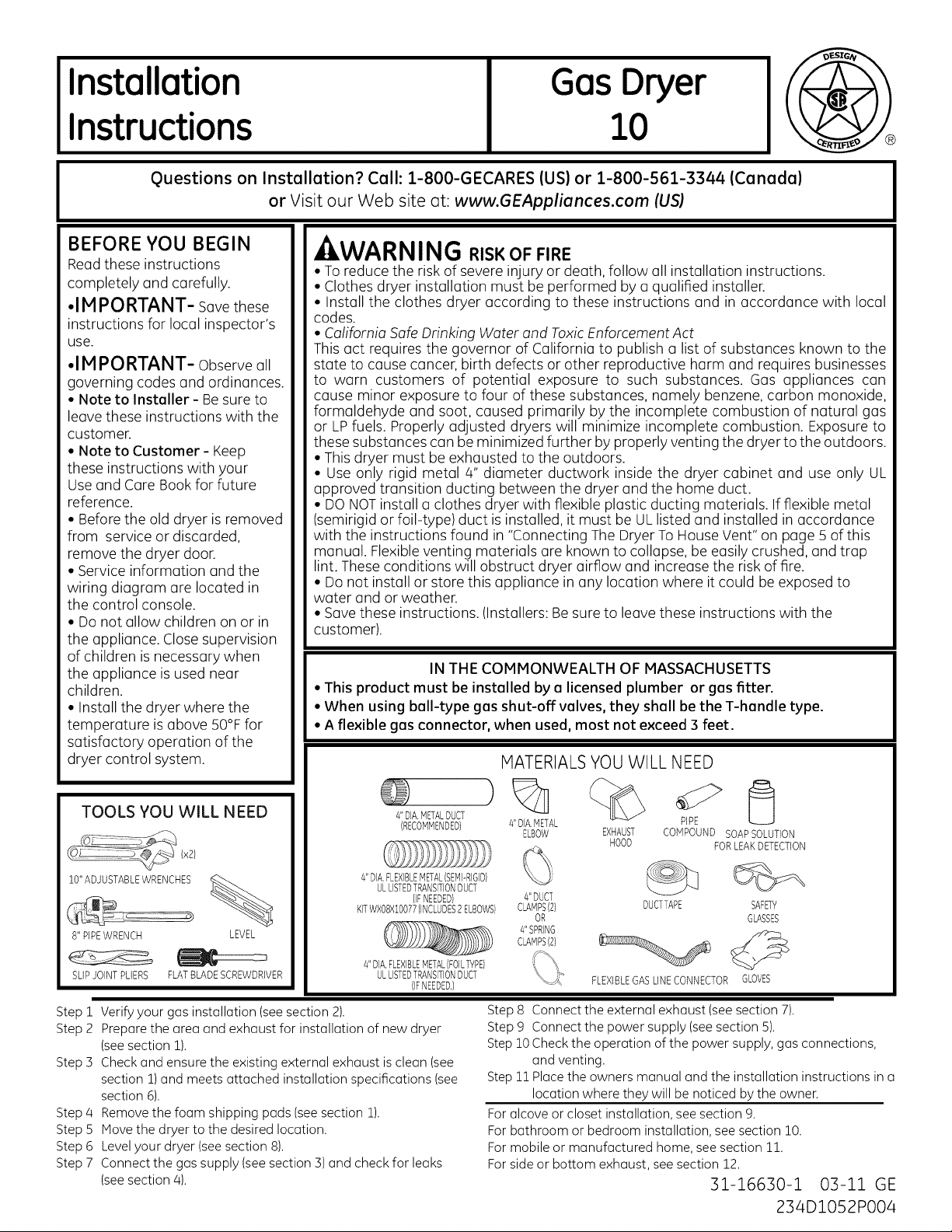
MATERIALSYOU WILL NEED
TOOLS YOU WILL NEED
10"ADJUSTABLEWRENCHES
8" PIPEWRENCH LEVEL
SLIPJOINTPLIERS FLATBLADESCREWDRIVER
Step 1
Verify your gas installation (see section 2).
Prepare the area and exhaust for installation of new dryer
Step 2
(seesection 1).
Step 5
Check and ensure the existing external exhaust is clean (see
section 1)and meets attached installation specifications (see
section 6).
Remove the foam shipping pads (see section 1).
Step 4
Step 5
Move the dryer to the desired location.
Step 6
Level your dryer (seesection 8).
Step 7
Connect the gas supply (seesection 3) and check for leaks
(seesection 4).
)
4"DIA,METALDUCT
(RECOMMENDED}
4"DIA,FLEXIBLEMETAL(SEMI-RIGID}
ULLISTEDTRANSITIONDUCT
KITWXO8X10077(INCLUDES2ELBOWS}
4"DIA,FLEXIBLEMETAL(FOILTYPE}
(IFNEEDED}
ULLISTEDTRANSITIONDUCT
(IFNEEDED.}
Step8 Connectthe externalexhaust(seesection7).
Step9 Connectthe powersupply(seesection5).
Step10Checkthe operationof the powersupply,gasconnections,
Step11Placethe ownersmanualandthe installationinstructionsina
Foralcoveor closet installation,see section9.
Forbathroomor bedroominstallation,seesection10.
Formobileor manufacturedhome,seesection 11.
Forsideor bottom exhaust,seesection12.
4"DIA,METAL
ELBOW EXHAUST
4"DUCT
CLAMPS(2}
OR
4"SPRING
CLAMPS(2}
FLEXIBLEGASLINECONNECTOR GLOVES
HOOD
PIPE
CONPOUND SOAPSOLUTION
FORLEAKDETECTION
DUCTTAPE SAFETY
GLASSES
and venting.
locationwheretheywillbe noticedbythe owner.
31-16630-1 03-11 GE
234D1052P004
Page 2
Installation Instructions
Minimum Clearance Other Than Alcove or Closet Installation
Minimum clearance to combustible surfaces and for air opening are: 0 in. clearance both sides, 1 in. front 3 in. rear.
Consideration must be given to provide adequate clearance for installation and service.
m PREPARING FOR INSTALLATION
OF NEW DRYER
TIP:Install your dryer before installing your washer.
This will allow better access when installing dryer exhaust.
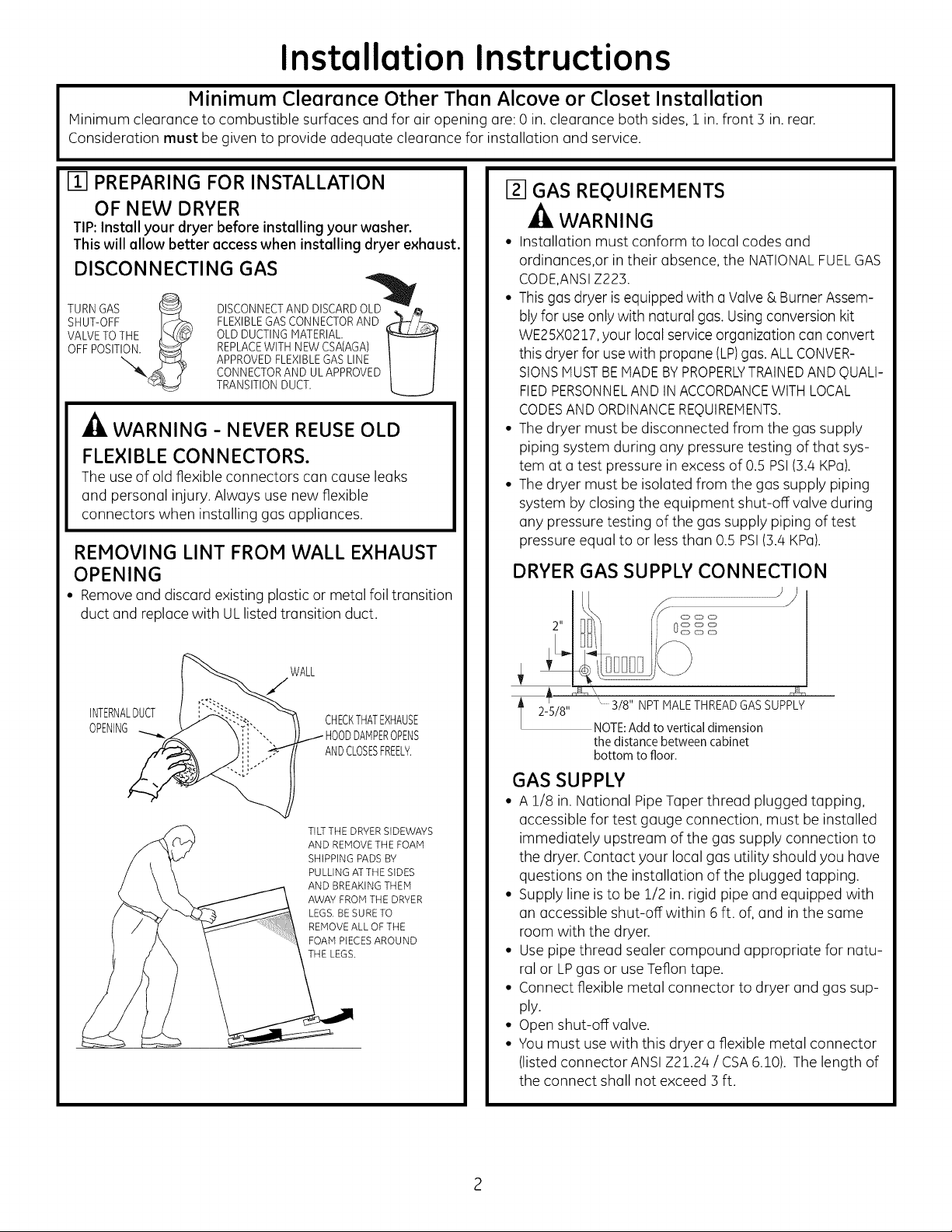
DISCONNECTING GAS
TURN GAS _ DISCONNECT AND DISCARD OLu_. _
SHUT-OFF IF:;_ FLEXIBLEGAS CONNECTOR AND _-h_-__,--_
VALVETOTHE _t_ _ OLD DUCTING MATERIAL
OFF POSITION._ REPLACEWITH NEW CSA(AGA)
APPROVED FLEXIBLEGAS LINE
CONNECTOR AND UL APPROVED
TRANSITIONDUCT.
A
WARNING - NEVER REUSE OLD
FLEXIBLE CONNECTORS.
The use of old flexible connectors can cause leaks
and personal injury. Always use new flexible
connectors when installing gas appliances.
REMOVING LINT FROM WALL EXHAUST
OPENING
• Removeand discard existing plastic or metal foil transition
duct and replace with ULlisted transition duct.
Izl GAS REQUIREMENTS
-_ WARNING
• Installation must conform to local codes and
ordinances,or intheir absence, the NATIONALFUELGAS
CODE,ANSIZ223.
• This gas dryer is equipped with o Valve & Burner Assem-
blyfor use only with natural gas. Usingconversion kit
WE25X0217,your local service organization con convert
this dryer for usewith propane (LP)gas. ALLCONVER-
SIONSMUSTBEMADEBYPROPERLYTRAINEDANDQUALI-
FIEDPERSONNELAND IN ACCORDANCEWITHLOCAL
CODESANDORDINANCEREQUIREMENTS.
• The dryer must be disconnected from the gas supply
piping system during any pressure testing of that sys-
tem at a test pressure in excess of 0.5 PSI(3.4 KPa).
• The dryer must be isolated from the gas supply piping
system by closing the equipment shut-off valve during
any pressure testing of the gas supply piping of test
pressure equal to or less than 0.5 PSI(3.4 KPa).
DRYER GAS SUPPLY CONNECTION
J#
WALL
INTERNALDUCT
OPENING ODDAMPEROPENS
CHECKTHATEXHAUSE
ANDCLOSESFREELY.
TILTTHE DRYERSIDEWAYS
AND REMOVETHE FOAM
SHIPPING PADS BY
PULLING ATTHE SIDES
AND BREAKING THEM
AWAY FROM THE DRYER
LEGS, BE SURE TO
REMOVEALL OF THE
FOAM PIECESAROUND
THE LEGS,
3/8" NPT MALE THREADGAS SUPPLY
NOTE:Add to vertical dimension
the distance between cabinet
bottom to floor.
GAS SUPPLY
• A 1/8 in. National PipeTaper thread plugged tapping,
accessible for test gauge connection, must be installed
immediately upstream of the gas supply connection to
the dryer. Contact your local gas utility should you have
questions on the installation of the plugged tapping.
• Supply line is to be 1/2 in. rigid pipe and equipped with
an accessible shut-off within 6 ft. of, and in the same
room with the dryer.
• Use pipe thread sealer compound appropriate for natu-
ral or LPgas or use Teflon tape.
• Connect flexible metal connector to dryer and gas sup-
ply.
• Open shut-off valve.
• You must use with this dryer a flexible metal connector
(listed connector ANSIZ21.24 / CSA6.10). The length of
the connect shall not exceed 3 ft.
2
Page 3
Installation Instructions
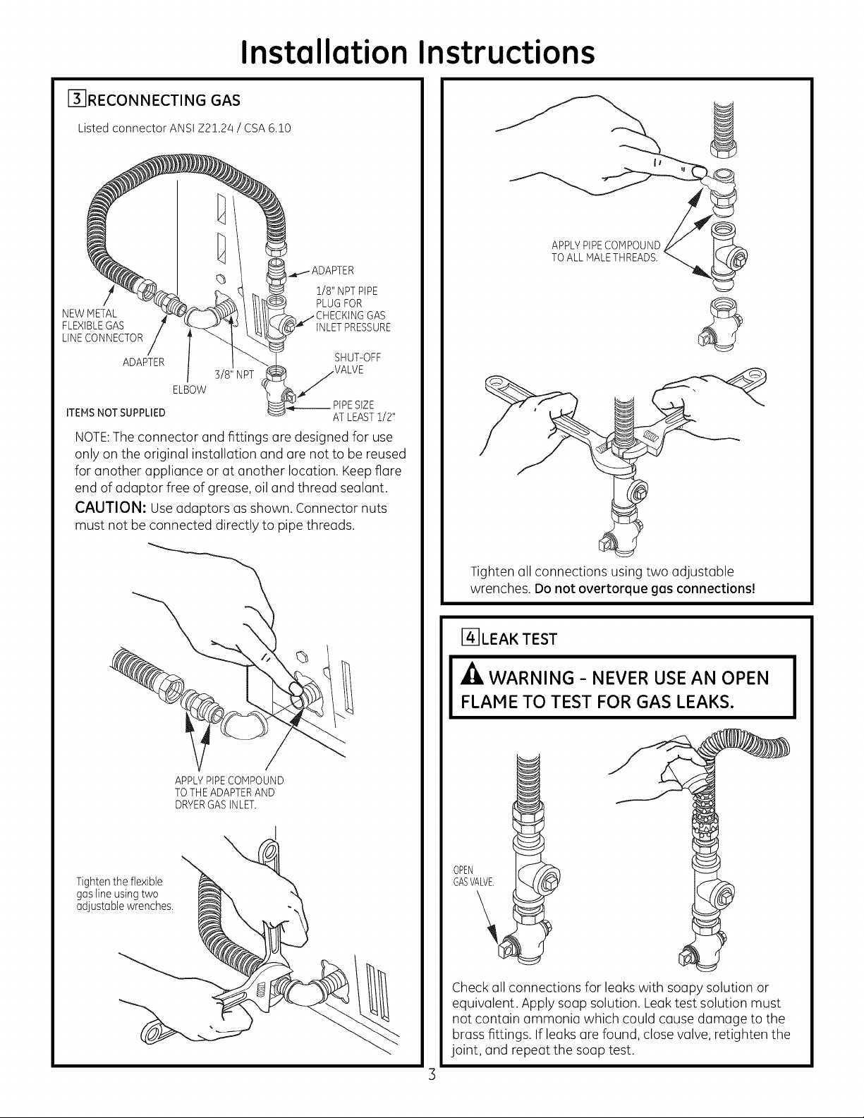
F3-IRECON NECTING GAS
Listed connector ANSI Z2!.24 / CSA 6.!0
1/8" NPTPIPE
PLUGFOR
NEWMETAL GAS
FLEXIBLEGAS INLETPRESSURE
LINECONNECTOR
ADAPTER SHUT-OFF
3/8" NPT VALVE
ELBOW
__PIPESIZE
ITEMSNOT SUPPLIED AT LEASTi/2"
NOTE: The connector and fittings are designed for use
only on the original installation and ore not to be reused
for another appliance or at another locution. Keep flare
end of adaptor free of grease, oil and thread sealant.
CAUTION: Use adaptors ms shown. Connector nuts
must not be connected directly to pipe threads.
APPLYPIPECOMPOUND
TOALL rVlALETHREADS.
©
Tighten the flexible
gas line using two
adjustable wrenches.
\
APPLYPIPECOMPOUND
TOTHE ADAPTERAND
DRYERGASINLET.
Tighten all connections using two adjustable
wrenches. Do not overtorque gas connections!
r4-]LEA K TEST
-_ WARNING- NEVER USE AN OPEN
FLAME TO TEST FOR GAS LEAKS.
GASVALVE.
OPEN
Check all connections for leaks with soapy solution or
equivalent. Apply soap solution. Leak test solution must
not contain (]mmonia which could cause damage to the
brass fittings. If leaks (]re found, close valve, retighten the
joint, and repeat the soup test.
Page 4
Installation Instructions
F5]ELECTRICAL CONNECTION INFORMATION
A
WARNING- TO REDUCE THE RISK
OF FIRE, ELECTRICAL SHOCK, AND
PERSONAL INJURY:
• DO NOT USE AN EXTENSION CORD
OR AN ADAPTER PLUG WITH THIS
APPLIANCE.
Dryer must be electrically grounded in accordance
with local codes and ordinances, or in the absence
of local codes, in accordance with the NATIONAL
ELECTRICALCODE,ANSI/NFPANO.70.
ELECTRICAL REQUIREMENTS
This appliance must be supplied with 120V,60Hz, end
connected to e properly grounded branch circuit, pro-
tected by e 15- or 20-amp circuit breaker or time delay
fuse. If electrical supply provided does not meet the
above specifications, it is recommended that a licensed
electrician install an approved outlet.
WARNING - THIS DRYER IS
EQUIPPED WITH A THREE-PRONG
(GROUNDING) PLUG FOR YOUR PROTEC-
TION AGAINST SHOCK HAZARD AND
SHOULD BE PLUGGED DIRECTLY INTO A
PROPERLY GROUNDED THREE-PRONG
RECEPTACLE. DO NOT CUT OR REMOVE
THE GROUNDING PRONG FROM THIS
PLUG.
161EXHAUST INFORMATION
WARNÁNG -IN CANADAANDINTHE
UNITED STATES, THE REQUIRED EXHAUST
DUCT DIAMETER IS 4in (102mm). DO NOT
USE DUCT LONGER THAN SPECIFIED IN THE
EXHAUST LENGTH TABLE.
Using exhaust longer than specified length will:
• Increase the drying times and the energy cost.
• Reduce the dryer life.
• Accumulate lint, creating a potential fire hazard.
The correct exhaust installation is YOUR
RESPONSIBILITY.Problems due to incorrect
installation are not covered by the warranty.
Remove and discard existing plastic or metal foil
transition duct and replace with UL listed transition duct.
The MAXIMUM ALLOWABLE duct length and number of
bends of the exhaust system depends upon the type of
duct, number of turns, the type of exhaust hood (wall
cap), and all conditions noted below. The maximum duct
length for rigid metal duct is shown in the table below.
EXHAUST LENGTH
RECCOMMENDEDMAX. LENGTH
ExhaustHoodTypes
I
......._1 4" _ ......
No.of 90°
Elbows
0
1
2
3
4
Rigid
Metal
90 Feet
60 Feet
45 Feet
35 Feet
25 Feet
ENSURE PROPER GROUND EXISTS BEFORE USE
IF LOCAL CODES PERMIT,
AN EXTERNALGROUND WIRE
(NOT PROVIDED), WHICH MEETS
LOCAL CODES, MAY BEADDED
BYATTACHING TO THE GREEN
GROUND SCREW ON THE REAR
OF THE DRYER,AND TO A GROUNDED
METAL COLD WATER PIPE OR OTHER
ESTABLISHED GROUND.
EXHAUST SYSTEM CHECK LIST
HOOD OR WALL CAP
• Terminate in a manner to prevent back drafts or entry of
birds or other wildlife.
• Termination should present minimal resistance to
the exhaust air flow and should require little or no
maintenance to prevent clogging.
• Never install a screen in or over the exhaust duct. This
could cause lint build up.
• Wall caps must be installed at least 12 in. above ground
level or any other obstruction with the opening pointed
down.
SEPARATIONOFTURNS
For best performance, separate all turns by atleast 4 ft.
of straight duct, including distance between last turn and
exhaust hood.
TURNSOTHERTHAN 90°
• One turn of 45oor less may be ignored.
• Two 45° turns should be treated as one 900turn.
• Each turn over 45° should be treated as one 900 turn.
Page 5

Installation Instructions
SEALING OF JOINTS
• All joints should be tight to avoid leaks. The male end of
each section of duct must point away from the dryer.
• The duct shall not be assembled with screws or other
fastening means that extend into the duct and catch lint.
• Duct joints can be made air and moisture-tight by
wrapping the overlapped joints with duct tape.
• Horizontal runs should slope down toward the outdoors
1/2 inch per foot.
INSULATION
Duct work that runs through an unheated area or is
near air conditioning should be insulated to reduce
condensation and lint build-up.
I-7-1EXHAUST CONNECTION
- WARNING - TO REDUCE THE RISK
OF FIRE OR PERSONAL INJURY:
• This clothes dryer must be exhausted to the outdoors.
• Use only 4" rigid metal ducting for the home exhaust
duct.
• Use only 4" rigid metal or UL-listed flexible metal (semi-
rigid or foil-type) duct to connect the dryer to the home
exhaust duct. It must be installed in accordance with
the instructions found in "Connecting the Dryer to
House Vent" on pages 5-6 of this manual.
• Do not terminate exhaust in a chimney, a wall, a ceiling,
gas vent, crawl space, attic, under an enclosed floor,
or in any other concealed space of a building. The
accumulated lint could create a fire hazard.
• Never terminate the exhaust into a common duct with
a kitchen exhaust system. A combination of grease and
lint creates a potential fire hazard.
• Do not use duct longer than specified in the exhaust
length table. Longer ducts can accumulate lint, creating
a potential fire hazard.
• Never install a screen in or over the exhaust duct. This
will cause lint to accumulate, creating a potential fire
hazard.
• Do not assemble ductwork with any fasteners that
extend into the duct. These fasteners can accumulate
lint, creating a potential fire hazard.
• Do not obstruct incoming or exhausted air.
• Provide an access for inspection and cleaning of the
exhaust system, especially at turns and joints. Exhaust
system shall be inspected and cleaned at least once a year.
THIS DRYER COMES READY FOR REAR
EXHAUSTING. IF SPACE IS LIMITED, USE
THE INSTRUCTIONS IN SECTION 12 TO
EXHAUST DIRECTLY FROM THE SIDES OR
BOTTOM OF THE CABINET.
STANDARD REAR EXHAUST
(Vented at floor level)
For straight line installation, connect
the dryer exhaust to the external
exhaust hood using duct tape or
clamp.
DUCT TAPE OR
DUCT CLAMP
4" METALDUCT CUT
TO PROPERLENGTH
JCT
DUCT TAPEOR
DUCT CLAMP
NOTE: WE STRONGLYRECOMMENDSOLID
METALEXHAUSTDUCTING. HOWEVER,IF
FLEXIBLEDUCTING ISUSEDIT MUST BE
UL-LISTEDMETAL,NOT PLASTIC.
STANDARD REAR EXHAUST
(Vented above floor level)
ELBOWHIGHLY
ELBOW HIGHLY
RECOMMENDED--
NOTE: ELBOWS WILL PREVENT DUCT
KINKING AND COLLAPSING.
CONNECTING THE DRYERTO HOUSE VENT
RIGID METAL TRANSITION DUCT
• For best drying performance, a rigid metal transition duct
is recommended.
• Rigid metal transition ducts reduce the risk of crushing and
kinking.
UL-LISTED FLEXIBLE METAL (SEMI-RIGID) TRANSITION
DUCT
• If rigid metal duct cannot be used, then UL-listed flexible
metal (semi-rigid) ducting can be used (Kit WXO8XlO077).
• Never install flexible metal duct in walls, ceilings, floors or
other enclosed spaces.
• Total length of flexible metal duct should not exceed 8 feet
(2.4m).
Page 6

Installation Instructions
• For many applications, installing elbows at both the dryer
and the wall is highly recommended (see illustrations
below). Elbows allow the dryer to sit close to the wall
without kinking and or crushing the transition duct,
maximizing drying performance.
•Avoid resting the duct on sharp objects.
UL-LISTEDFLEXIBLEMETALIFOIL-TYPE}TRANSITIONDUCT
• In special installations, it may be necessary to connect
the dryer to the house vent using a flexible metal (foil-
type) duct. A UL-listed flexible metal (foil-type) duct may
be used ONLYin installations where rigid metal or flexible
metal (semi-rigid) ducting cannot be used AND where a 4"
diameter can be maintained throughout the entire length
of the transition duct.
• In Canada and the United States, only the flexible metal
(foil-type) ducts that comply with the "Outline for Clothes
Dryer Transition Duct Subject 2158A" shall be used.
• Never install flexible metal duct in walls, ceilings, floors or
other enclosed spaces.
•Total length of flexible metal duct should not exceed 8 feet
(2.4m).
• Avoid resting the duct on sharp objects.
For best drying performance:
1.Slide one end of the duct over the clothes dryer outlet pipe.
2.Secure the duct with a clamp.
3.With the dryer in its permanent position, extend the duct
to its full length. Allow 2" of duct to overlap the exhaust pipe.
Cut off and remove excess duct. Keepthe duct as straight
as possible for maximum airflow.
4.Secure the duct to the exhaust pipe with the other clamp.
[] LEVELING AND STABILIZING YOUR
DRYER
Stand the dryer upright near the final location and adjust
the 4 leveling legs, at the corners, to ensure that the dryer
is levelfrom side to side and front to rear.
LEVEL LEVEL
FRONT-TO-BACK SIDE-TO-SIDE
4 LEVELING
LEGS
!
ELBOW
REOUIRED
oo;oLy4
191ALCOVE OR CLOSET INSTALLATION
• If your dryer is approved for installation in an alcove or
closet, it will be stated on a label on the dryer back.
•The dryer MUST be vented to the outdoors. See the
EXHAUSTINFORMATIONsection 6.
• Minimum clearance between dryer cabinet and adjacent
walls or other surfaces is:
0 in.either side
3 in.front
4 in. rear
• Minimum vertical space from floor to overhead cabinets,
ceiling, etc. is 52 in.
•Closet doors must be Iouvered or otherwise ventilated
and must contain a minimum of 60 sq. in. of open area
equally distributed. If the closet contains both a washer
and a dryer, doors must contain a minimum of 120 sq. in.
of open area equally distributed.
•The closet should be vented to the outdoors to prevent
gas pocketing in case of a gas leak in the supply line.
• No other fuel-burning appliance shall be installed in the
same closet with the dryer.
NOTE: WHEN THE EXHAUST DUCT IS LOCATED AT THE
REAROF THE DRYER,MINIMUM CLEARANCE FROM THE
WALL IS5.5 in.
Page 7

Installation Instructions
[i-6] BATHROOM OR BEDROOM INSTALLATION
•The dryer MUSTbe vented to the outdoors. See EXHAUST
INFORMATIONsection 6.
• The installation must conform with local codes or, in the
absence of local codes, with the NATIONALELECTRICAL
CODE,ANSI/NFPANO.70.
Iii]MOBILE OR MANUFACTURED HOME
INSTALLATION
•Installation must conform to the MANUFACTUREDHOME
CONSTRUCTION& SAFETYSTANDARD,TITLE 24, PART
32-80 or, when such standard is not applicable, with
AMERICAN NATIONAL STANDARDFOR MOBILE HOME,
ANSI/NFPANO.501B.
•The dryer MUST be vented to the outdoors with the
termination securely fastened to the mobile home
structure. (SeeEXHAUSTINFORMATIONsection 6).
•The vent MUSTNOT be terminated beneath a mobile or
manufactured home.
•The vent duct material MUSTBEMETAL.
• KIT 14-D346-33 MUST be used to attach the dryer
securely to the structure.
•The vent MUST NOT be connected to any other duct,
vent, or chimney.
•Do not use sheet metal screws or other fastening devices
which extend into the interior of the exhaust vent.
• Provide an opening with a free area of at least 25 sq. in.
for introduction of outside air into the dryer room.
Detach and remove the bottom or left side knockout as
desired. Removethe screw inside the dryer exhaust duct
and save. Pullthe duct out of the dryer.Protect sharp edges
around the knockout and exhaust opening with the tape.
FIXING
B A
131/2"
(1B1/4" for bottom venting)
Cut the duct as shown and keep portion A.
TAB LOCATION
BENDTAB
UP45o
• Dryers installed in residential garages must be elevated
18 inches (46cm) above the floor.
ITJIDRYER EXHAUST TO LEFT OR BOTTOM
CABINET
- WARNING - PROTECTYOUR
HANDS AND ARMS FROM SHARP EDGES
WHEN WORKING INSIDE CABINET.
REMOVE
SCREW
ANDSAVE,
Through the rear opening, locate the tab inthe middle of
the appliance base. Lift the tab to about 450 using a flat
blade screwdriver.
ADDING NEW DUCT
i i
FIXING
HOLE
Reconnect the cut portion (A)of the duct to the blower
housing. Make sure that the fixing hole is aligned with the
tab in the base. Use the screw saved previously to secure
the duct in place through the tab on the appliance base.
PORTION"A"
RIGHTOR
LEFTSIDE
EXHAUST
REMOVE
DESIRED
KNOCKOUT
IONEONLV)
Page 8

Installation Instructions
ADDING ELBOW AND DUCT FOR
EXHAUST TO LEFT OR RIGHT SIDE OF
CABINET
• Preassemble 4" elbow with 4" duct. Wrap duct tape
around joint.
• Insert duct assembly, elbow first, through the side
opening and connect the elbow to the dryer internal duct.
CAUTION: Be sure not to pullor domage the
electricalwiresinsidethedryerwhen insertingtheduct.
DUCT
z TAPE
ADDING COVER PLATE TO REAR OF
CABINET
P_TELA X "" """
(KITWE1M454)
Connect standard metal elbows and ducts to complete the
exhaust system. Cover back opening with a plate (Kit
WEIM454) available from your local service provider.
Placedryer infinal location.
-/ILWARNING-NEVER LEAVE THE
BACK OPENING WITHOUT THE PLATE.
•Apply duct tape as shown on thejoint between the dryer
internal duct and the elbow.
CAUTION:
Use4" rigid metal ducting only
inside the dryer. Internal duct
joints must be secured with
tape, otherwise they may sepa-
rate and cause a safety hazard.
ADDING ELBOW FOR EXHAUST
THROUGH BOTTOM OF CABINET
• Insert the elbow through the rear opening and connect it
to the dryer internal duct.
•Apply duct tape on the joint between the dryer internal
duct and elbow, as shown above.
TO REGISTER YOUR DRYER
CALL TOLL-FREE
1-888-269-1192
Prompt registration confirms your right to protection under
the terms of your warranty.
www.GEAppliances.com (US}
For Questions on Installation, Call: 1-800-GECARES(US)or
1-800-:361-3400 (Canada).
CAUTION:
Internal ductjoints must be securedwith tape,
otherwise they may separate and cause a
safety hazard.
Page 9

Instrucciones
Secadoraagas
de instalaci6n
_Preguntas sabre la instalaci6n? Llame al: 1-800-GECARES (EE.UU.) o 1-800-561-3344 (Canad(_)
o visJte nuestro sJtio Web en: www.GEAppliances.com (EE.UU.)
ANTES DE COMENZAR
Lea estas instrucciones par
completo y con detenimiento.
•IM PORTANTE - Guarde
estasinstruccionesparaelusade
inspectoreslocales
•IMPORTANTE -sigatodos
losc6digosy ordenanzasvigentes
• Nota al instalador - AsegQrese
de dejar estas instrucciones con el
consumidor.
• Nota al consumidor -Mantenga
estasinstruccionescon elManual de
usay cuidados parareferenciafutura.
• Antes de que lasecadora antigua
sea retirada del servicio o elimi-
nada, quffele la puerta.
• Lainformaci6n sabre reparaciones
y eldiagrama delcableado se en-
cuentran en la consolade control.
• No permita que ni_os se suban
o se metan dentro del aparato. Se
requiere una supervisi6n estricta
cuando elaparato es utilizado
cerca de ni_os.
• Instale la secadora en lugares
donde la temperatura sea mayor
a 50°Fpara un funcionamiento
satisfactorio del sistema de control
de la secadora.
HERRAMIENTAS NECESARIAS
- ADVERTENCIA mESGODEINCENDIO
• Para reducir el riesgo de una lesi6n grave o de muerte, cumpla con todas las
instrucciones de instalaci6n.
• La instalaci6n de la secadora debe efectuarla un instalador calificado.
• Instale la secadora de ropa de acuerdo con estas instrucciones yen cumplimiento
con los c6digos locales.
• key de California para el agua potabley los t6xicos
Estaleyexigeque el Gobernadorde California publique una lista de sustancias que segOn
el estado provoquen c6ncer,defectoscong_nitos u otros da_os reproductivos,y exige alas
empresas que adviertan a los clientes sabre la exposici6n potencial a dichas sustancias.
Losaparatos a gas pueden provocar una exposici6n mfnima a estas sustancias,a saber,
benceno, mon6xido de carbono, formaldehfdo y hollfn, generados principalmente par la
combusti6n incompleta de gas natural o combustibles LR Siseajustan bien las secadoras,
la combusti6n incompleta se ver6 minimizada. La exposici6n a estas sustancias puede
minimizarse aLinm6s mediante unaventilaci6n adecuada haciaelexterior.
• Estasecadora debe tener una salida al exterior.
• Utilices61ounconductorfgidodemetaldeundi6metrode4"dentrodelgabinetedelasecadora
yuses61ounconductodetransici6naprobadoparULentrelasecadorayelconductodom_stico.
• NO instale una secadora de ropa con conductos de pl6stico flexible. Sise instala un
conducto flexible de metal (semi rfgidoo de tipo papel de aluminio),debe estar aprobado
par ULe instalarse de acuerdo con las instrucciones de "C6mo conectar la secadora a la
ventilaci6ndom_stica"de lap6gina 5 deeste manual. Losmaterialesde ventilaci6n flexibles
a menudo se desploman, se aplastan y atrapan pelusas. Estascondiciones obstruyen la
corriente de aire dela secadorae incrementanel riesgode incendio.
• No instale o almacene este aparato en un lugar donde sevea expuesto al agua y/o
alas inclemencias deltiempo.
• Guarde estas instrucciones. (Instaladores: AsegOrese de dejar estas instrucciones
al consumidor).
ENELESTADODEMASSACHUSETTS
• Esteproducto debeinstalarlo un plomero o ungasfitero matriculado.
• Cuandousev(ilvulas esf@ricasde cierre de gas,deber(in ser deltipo de manija enT.
•Si seusauna conexi6nflexible para gas, @stano debesuperar los 3 pies.
10
MATERIALESNECESARIOS
LLAVESAJUSTABLESDE10"
LLAVEPARATUBOSDE8"
ALICATESDE
JUNTADESLEANTE
DESTORNILLADORPLANO
(x2)
%
NIVEL
coNDuceD
(RECOMENDADO}
CONDUCTODETP_ANBICIONDE"vIET,BL ABRAZADERAB
FLEXIBLE(SEMIRIGIDO}DE4"DEDIA, DERESORTEDE4"(2}
APROBADOPORUL(ElFUERANECESARIO}
KITWXO8XlO077(INCLUYE2CODOS} _ ALIVIODETENSION
CONDUCTODETRANSICIONDE METAL
FLEXIBLE(TIPOPAPELDEALUMINIO}DE4"DEDIA, (KITWE1MaB4}
APROBADOPORUL(ElFUERANECEBARIO}
)
ABRAZADERABCODODEMETJ_L
DECONDUCTODE4"(2} DE4"DEDIA, CA'vIPANA GAFAS
0 DEBALIDA DEBEGURIDAD
GUANTEB DEY/' RECONOCIDO
CINTAADHEBIVA PORUL
(NOPROVISTACON
CLASIFICADOPOR
UL120/240V,30A
CON ] 0 4 CLAVIJAB
IDENTIFIQUEELTIPO
DEENCHUFEBEGUN
ELTOMACORRIENTE
DELAVIVIENDAANTES
DECOMPRARELCABLE.
KITDECABLE
DEENERG'A
DELASECADORA
LABECADORA}
I
Paso 1
Verifique su instalaci6n de gas (ver secci6n 2).
Paso 2
Prepare el area y la salida para la instalaci6n de la nueva
secadora (ver secci6n 1).
Paso 3
Verifique y asegOrese de que la salida al exterior existente
est# limpia (ver secci6n 1)y que cumpla con las especifica-
ciones de instalaci6n incluidas (ver secci6n 6).
Paso 4
Quite las almohadillas de espuma para env[o (versecci6n 1).
Paso 5
Desplace la secadora a la ubicaci6n deseada.
Paso 6
Nivele su secadora (ver secci6n 8).
Paso 7
Conecte el suministro de gas (ver secci6n 3)y controle la pres-
encia de p#rdidas (ver secci6n 4).
Paso 8 Conecte la salida al exterior (ver secci6n 7).
Paso 9 Conecte el suministro de energfa (versecci6n 5).
Paso 10 Verifique el funcionamiento del suministro de energfa, las
conexiones de gas y la ventilaci6n.
Paso 11 Coloque el manual del propietario y las instrucciones de
instalaci6n en un lugar de f(icil acceso para el propietario.
Parainstalaci6nen nicho o closet,ver secci6n9.
Parainstalaci6nen ba_oso dormitorios,versecci6n10.
Paracasasm6vileso prefabricadas,ver secci6n11.
Parasalidaslateraleso par laparte inferior,versecci6n12.
31-16630-1 03-11 GE
234D1052POO4
Page 10

Instruccionesde instalaci6n
Espacio minima diferente a instalaci6n en nichos o closets.
Losespacioslibresm[nimosrespectodesuperficiescombustiblesy deaberturasdeaireson:Espaciode0 pulg.a amboslados,1pulg.enel
frentey 3 pulg.enla partetrasera. Debetenerseencuentaunespaciolibreadecuadoparaunfuncionamientoy reparaci6ncorrectos.
I-_ PREPARACION PARA LA INSTALACION
DE UNA SECADORA NUEVA
CONSEJO:Instale su secadora antes de instalar la lava-
dora. Esto permitir6 un mejor acceso cuando instale la
salida de la secadora.
C6MO DESCONECTAR EL GAS
DESCONECTEY ELIMINE
ELCONECTOR DE GAS
FLEXIBLEANTIGUa Y
GIRE LAVALVULA ___'_
DE CIERRE DE GAS If-_'_
A hA POSICION OFF IL..((Y_;
/APAGADO) _'6_
LOSCONDUCTOS VIEJOS.
REEMPLACELOSCON ,% /_
UN N,UEVOCONECTOR _7_
DE LINEA DEGAS FLEXIBLE I--_l
APROBADOPaR CSA {AGA)Y. I I
UN CONDUCTO DE TRANSICIONI I
APROBADOPORUY L_S
A
ADVERTENCIA - NUNCA VUELVA A
USAR CONECTORES FLE×IBLES GAS-
TADOS.
Elusa de conectores flexibles usados puede provocar
p#rdidas de gas y lesiones personales. Siempre utilice
conectores flexibles nuevos cuando instale aparatos
de gas.
I_ REQUERIMIENTOS DE GAS
ADVERTENCIA
• La instalaci6n debe cumplir con c6digos oordenanzas
locales, o si no las hubiera, con el CODIGONACIONALDE
GAS,ANSIZ223.
• Esta secadora agas est6 equipada con un montaje de
v61vulay quemador para utilizar s61ocon gas natural.
Mediante el kit de conversi6n WE25×0217, la organizaci6n
de atenci6n local puede convertir esta secadora para su
usa con gas propano (LP).TODASLASCONVERSIONES
DEBENLLEVARLASA CABOPERSONALCAPACITADOY
CALIFICADOENCUMPLIMIENTOCONCODIGOSLOCALESY
REQUERIMIENTOSDEORDENANZAS.
• Losecadora debe desconectarse del sistema de tuber[a de
suministro de gas durante cualquier prueba de presi6n del
sistema con una presi6n de prueba mayor a 0.5 PSI(:3.4KPa).
• La secadora debe aislarse del sistema de tuberfa de sum-
inistro de gas cerrando lav61vula de cierre del equipo du-
rante cualquier puesta a prueba del sistema en presiones
de prueba iguales o menores a 0.5 PSI(:3,4.4KPa).
CONE×I6N DE SUMINISTRO DE GAS DE
LA SECADORA
COMO QUITAR PELUSA DE LA ABERTURA
DE LA SALIDA DE LA PARED
• Quite y descarte elconducto de transici6n existente de
pl6stico ode papel de aluminio y coloque un conducto de
transici6n aprobado par UL.
PARED
ABERTURA DE
CONDUCTOINTERNA
VERIFIQUE QUE
EL REGULADOR
DE LA CAMPANA
DE SALIDA SE ABRA
Y CIERRE LIBREMENTE
INCLINE LA SECADORA
DE COSTADO YQUITE
LAS ALMOHADILLAS
DE ESPUMA PARA ENViO
TOM#,NDOLAS DE LOS
COSTADOS Y
ARRANCANDOLAS DELAS
PATASDE LA SECADORA.
ASEGURESE DEQUITAR
TODAS LAS PtEZAS
DE ESPUMA UBICADAS
ALREDEDOR DE LAS PATAS.
"-- SUMINISTRODE GAS ROSCAMACHO NPTDE 3/8"
NOTA: Agregue a la dimensi6n vertical la dJstancia
entre la parte inferior del gabinete yel piso.
SUMINISTRO DE GAS
Debe instalarse una toma a rosca de 1/8" NPT, accesible
para una conexi6n del man6metro de prueba, inme-
diatamente en sentido ascendente de la conexi6n de
suministro de gas hacia la secadora. Si tiene dudas sabre
la instalaci6n de la toma, comun[quese con su empresa
proveedora de gas local.
Lo I[nea de suministro debe ser de tuberfa r[gida de 1/2"y
debe contar con un cierre accesible dentro de los 6 pies
de la secadora, dentro de la misma habitaci6n donde se
encuentra la misma.
Utilice compuesto sellador para rosca de tuberia apropia-
do para gas natural o LP o utilice cinta de Teflon.
Una el conector de metal flexible a la secadora y al sum-
inistro de gas.
Abra la v61vulade cierre.
• Con esta secadora debe usarse un conector de metal
flexible (conector aprobado ANSIZ21.24 / CSA6.10). La
Iongitud de la conexi6n no deber6 superar los :3pies.
Page 11

Instruccionesde instalaci6n
F31COMO RECONECTAR EL GAS
Conector aprobado ANSIZ2124 / CSA6.t0
TAPON DETUBER[A
CONECTORNUEVO )LARLA
DEL[NEA DEGAS PRESIONDEENTRADA
DEMETAL FLEXIBLE DEGAS
ADAPTADOR VALVULADECIERRE
CoDoNPT DE 3/8" j
ITEMSNOT SUPPLIED TAP1ANODETUBER[A
NOTA:Elconector y los accesorios se encuentran dis-
eBados para usarse s61oen la instalaci6n original y no
deben volverse a usar en otro aparato o en otra ubi-
caci6n. Mantenga elextremo abocinado del adaptador
libre de grasa, aceite y sellador de roscas.
NPTDE 1/8" PARA
AL MENOS1/2"
APLIOUE COMPUESTO
PARA TUBERiA
EN TODAS
LAS ROSCAS MACHO.
©
%
PRECAUClON:Utilice los adaptadores como se indica.
Lastuercas de conexi6n no deben conectarse directa-
mente en las roscas de la tuber[a.
APLQUE COMPUESTOPARATUBER[A
AL ADAPTADORYA LA ENTRADA
DEGAS DE LASECADORA.
Ajuste la tube@ flexible
de gas utilizando
dos Ilaves ajustables.
Ajuste todas las conexiones mediante dos Ilaves ajustables.
iNo ajuste de m6s las conexiones de gas!
I-4-IPRUEBA DE DETECCION DE PI_RDIDAS
UNA LLAMA ABIERTA PARA DETECTAR
.4L ADVERTENCIA - NUNCA UTILICE
PERDIDAS DE GAS.
ABRA
DEGAS.
LAVALVULA
Controle todas lasconexiones con una soluci6n jabonosa o
un elemento equivalente. Aplique una soluci6n jabonosa.
Lasoluci6n para controlar p@rdidasno debe contener
amoniaco, ya que este producto puede da_ar losaccesorios
de bronce. Sisedetectan p@rdidas,cierre la v61vula,vuelva a
ajustar lajunta y repita la prueba de la soluci6n jabonosa.
Page 12

Instruccionesde instalaci6n
rS-11NFORIVlACIONSOBRE CONEXIONES EL¢CTRICAS
.4L ADVERTENCIA - PARA REDUCIR
EL RIESGO DE INCENDIO, DESCARGA
ELI_CTRICA Y LESIONES PERSONALES:
• NO UTILICE UN CABLE DE EXTEN-
SION O UN ENCHUFE ADAPTADOR
CON ESTE APARATO.
Lasecadora debe contar con una conexi6n
el6ctrica a tierra en cumplimiento con los c6digos
y ordenanzas locales, o si 6stos no existieran, de
acuerdo con el CODIGOELI_CTRICONACIONAL,
ANSI/NFPAN°. 70.
REQUISITOS ELI_CTRICOS
Este aparato debe contar con un suministro de 120V,
60Hz, debe estar conectado a un circuito derivado
individual con una adecuada conexi6n a tierra y deben
contar con la protecci6n de un interruptor de circuitos
o fusible de tiempo retardado de 15 o 20 amperios. Si
el suministro el_ctrico provisto no cumple con las espe-
cificaciones anteriores, se recomienda que un electri-
cista con licencia instale un tomacorriente aprobado.
-4L ADVERTENCIA - ESTASECADORAEST/_
EQUIPADACON UN ENCHUFEDETRES
CLAVIJAS(CONE×I6N A TIERRA)PARASU
PROTECCIONCONTRA DESCARGASELEC-
TRICASY DEBEENCHUFARSEDIRECTA-
MENTE EN UN TOMACORRIENTE DETRES
CLAVIJASCON ADECUADA CONEXION A
TIERRA. NO CORTE0 QUITE LACLAVIJADE
CONE×ION A TIERRADE ESTEENCHUFE.
INFORMACI6N DE SALIDA
A____..__m_..__.__
411ADVERTENCIA - EN CANADA Y LOS
ESTADOS UNIDOS, EL DIAMMETRO DE CON-
DUCTO DE SALIDA REQUERIDO ES DE4 PULG.
(102 mm). NO UTILICE UN CONDUCTO DE UNA
LONGITUD MMAYORA LA ESPECIFICADA EN LA
TABLA DE LONGITUD DE SALIDA.
AIutilizar una salidade mayor Iongituda laespecificada se:
• Incrementar@nlostiempos de secado y el costo de energia.
• Reducir5 la vida 0til de la secadora.
• Acumular5 pelusa, Ioque podria generar un riesgo
potencial de incendio. La correcta instalaci6n de salida
es SURESPONSABILIDAD.Los problemas generados
pot una instalaci6n incorrecta no se encuentran cubi-
ertos por la garantia. Quite y descarte el conducto de
transici6n existente de pl@sticoo de papel de aluminio y
coloque un conducto de transici6n aprobado por UL.
La Iongitud M/i,×IMAPERMITIDAdel conducto y la
cantidad de codos del sistema de salida dependen
del tipo de conducto, la cantidad de curvas, la clase
de campana de salida (cubierta de pared) y todas las
condiciones indicadas a continuaci6n. La Iongitud
mc_ximadel conducto para conductos rigidos de metal se
indica en la siguiente tabla.
L©lXItul I UlJ IDL 3ALIIDA
LONGITUDMAXIMARECOMENDADA
Tipos de compono de solido
Cantidad de codos
de90grados
0
1
2
3
4
Metal
rigido
90 Feet
60 Feet
45 Feet
35 Feet
25 Feet
VERIFIQUE OUE HAYA UNA CONE×ION A TIERRA
ADECUADA ANTES DEL USO.
SILO PERMITENLOSCODIGOS
LOCALES,PUEDEAGREGARSE
UN CABLEATIERRAEXTERNO
(NOPROVISTO),q)UECUMPLA
CONLOSCODIGOSLOCALES,SUJETANDOLOALTORNILLOVERDE
DECONEXIONATIERRAENLA PARTETRASERADELASECADORA,
YALATUBERJADEAGUAFR[ADEMETALCONCONEXION
ATIERRAUOTRACONEXIONATIERRAESTABLECIDA.
LISTA DECONTROL DEL SISTEMA DESALIDA
CAMPANA O CUBIERTADE PARED
• Instale la salida de modo de evitar contracorrientes o el
ingreso de p@jarosu otros insectos o animales.
• La boca de salida debe presentar una resistencia
minima al flujo de salida y debe requerir poco o ning0n
mantenimiento para evitar las obstrucciones.
• Nunca instale un filtro dentro o sobre el conducto de
salida. Esto podrfa provocar una acumulaci6n de pelusa.
• Las cubiertas de pared deben instalarse por Io menos a
12" sobre el nivel del suelo o cualquier otra obstrucci6n
con laabertura apuntando hacia abajo.
SEPARACIONDECURVAS
Para un mejor desempeflo, separe todas las curvas con por
Io menos 4 pies de conducto recto, incluyendo la distancia
entre la Oltima curva y la campana de salida.
GIROSQUE NO SON DE 90°
• Un giro de 45o o menos puede ignorarse.
• Dos giros de 45odeben tratarse como un giro de 90°.
• Todos los giros de mc_sde/45odeben tratarse como un
giro de 90°.
Page 13

Instruccionesde instalaci6n
SELLADODEJUNTAS
• Todaslosjuntas deben estar bien selladaspara evitar
p@didas.Elextremo macho de cada secci6n deconducto
debe apuntar en direcci6n opuesta a la secadora.
• Elconducto no deber6 instalarse con tornillos u otros
medios de sujeci6n que seextiendan dentro del
conducto y enganchen pelusas
• Lasjuntas de los conductos deben ser herm6ticas al aire
y a la humedad mediante lasuperposici6n dejuntas con
cinta aislante o cinta de aluminio
• Los tramos horizontales deben tener una inclinaci6n
hacia el exterior de 1/2"por pie
AISLACION
Losconductos instalados a trav_s de un 6rea sin calefacci6n
o ubicados cerca de un acondicionador deaire deben aislarse
para reducir la condensaci6n y la acumulaci6n de pelusas.
I-7-1CONE×IeN A LA SALIDA
-4LADVERTENCIA - PARAREDUCIR
EL RIESGO DE INCENDIO O DE
LESIONES PERSONALES:
• Estasecadora de ropa debe tener una salida al exterior.
• Utilice s61oun conducto de metal r[gido de 4" para el
conducto de salida dom6stico
• Use s61oun conducto de metal rigido de 4" o de metal
flexible (semirigido o de tipo papel de aluminio)aprobado
por UL para conectar la secadora al conducto de
salida dom@stico. Debe instalarse de acuerdo con las
instruccionesincluidasen "C6moconectar lasecadoraa la
ventilaci6n dom_stica" de lasp6ginas 5-6 de estemanual.
• No instale la boca de salida dentro de una chimenea,
pared, cielorraso, ventilaci6n de gas, espacio entre
pisos,6tico, bajo un piso con cerramiento o en cualquier
otro espacio oculto de un edificio. La acumulaci6n de
pelusas podria provocar un riesgo de incendio.
• Nunca instale la boca de salida dentro de un conducto
comOn con el sistema de salida de la cocina La
combinaci6n de grasa y pelusas podr[a provocar un
riesgo de incendio
• No utilice un conducto de una Iongitud mayor a la
especificada en la tabla de Iongitud de salida Los
conductos m6s largos acumulan pelusa, Ioque genera
un riesgo potencial de incendio
• Nunca instale un filtro dentro o sobre el conducto de
salida Esto provocar6 la acumulaci6n de pelusas, Io
que genera un riesgo potencial de incendio
• No arme la red de conductos con sujeciones que
se extiendan dentro del conducto Estas sujeciones
pueden acumular pelusa, Io que genera un riesgo
potencial de incendio
• No obstruya elaire que entra y sale.
• Incluya unacceso para inspecci6n y limpieza del sistema
de salida, especialmente en las curvas y juntas. El
sistema desalida debe inspeccionarse y limpiarse por Io
menos una vez al aSo.
ESTASECADORAVIEN ELISTA PARAUTI LIZAR UNA
SALIDA POR LA PARTETRASERA. SI EL ESPACIO
ES LIMITAI;)O, UTILICE LAS INSTRUCCIONES DE
LA SECCION 22 PARA UNA SALIDA DIRECTA
DESDE LOS LADOS O PARTE INFERIOR DEL
GABINETE.
SALIDA TRASERA ESTANDAR
(Ventilaci6n a nivel del suelo)
Para una instalaci6n en linea recto, conecte
la salida de la secadora a la campana
de salida al exterior con cinta aislante
o una abrazadera.
ABERTURA DE
CONDUCTO EXTERIOR
CINTA AISLANTE
O
DE CONDUCTO
CONDUCTO DE METAL
DE 4" CORTADO
CON LA LONGITUD ADECUADA
CINTA AISLANTE O
ABRAZADERA DE CONDUCTO
NOTA: RECOMENDAMOS ENFATICAM ENTE EL USO
DECONDUCTOS DE SALIDA DE METAL SOLIDO,
SIN EMBARGO, SI SE USAN CONDUCTOS FLE×IBLES
ESTOSDEBEN SER DE METAL APROBADOS POR UL,
NO DE PL/_STICO,
SALIDA TRASERA EST_,NDAR
(Ventilaci6n sobre el nivel del suelo)
SERECOHIENDA
ELUSODECODOS _
CONFIGURACION
RECOHENDADA
PARAHINIHIZAR
LAS OBSTRUCCIONES
DELA SALIDA.
i I J
SERECOHIENDA
ELUSO DECODOS-
NOTA: LOS CODOS EVITAN QUE LOS
CONDUCTOS SE DOBLEN O CAIGAN.
C6MOCONECTAR LA SECADORA A LA VEN-
TILACI6N DOMI_STICA
CONDUCTO DETRANSICI6N DEMETALRIGIDO
• Para un mejor desempe_o de secado, se recomienda un
conducto de transici6n de metal rigido.
• Los conductos de transici6n de metal rigidos reducen el
riesgo de aplastamientos y torceduras.
CONDUCTODETRANSICIONDE METALFLEXIBLE
(SEMI-RJGIDO)APROBADOPORUL
• Si no puede utilizarse un conducto de metal r[gido, en-
tonces puede usarse un conducto de metal flexible (semi-
r[gido) aprobado por UL (Kit WX08X10077).
• Nunca instale conductos de metal flexibles en paredes,
cielorrasos, pisos u otros espacios cerrados.
• La Iongitud total del conducto de metal flexible no deber6
superar los 8 pies (2./4m).
Page 14

Instruccionesde instalaci6n
• Para muchas aplicaciones, se recomienda enf6ticamente la
instalaci6ndecodosenlasecadorayen lapared(verilustraciones
de abajo).Loscodos permitenque la secadorase ubiquecerca
de la paredsin torcero aplastarel conductode transici6n,Ioque
potenciaal m6ximo eldesempe_ode secado.
• No coloque el conducto sobre objetos afllados.
CONDUCTO DE TRANSICION DE METAL FLEXIBLE
(SEMI-RJGIDO)APROBADOPORUL
• Eninstalaciones especiales, puede ser necesario conectar la
secadora a la ventilaci6n dom6stica utilizando un conducto
de metal flexible (tipo papel de aluminio). Puede utilizarse
un conducto de metal flexible (tipo papel de aluminio)
aprobado por UL SOLO en instalaciones en las que no
pueden usarse conductos de metal r[gidos o flexibles (semi-
r[gidos)Yen las que puede mantenerse un di6metro de 4" a
Iolargo de todo el conducto de transici6n.
• En Canad6 y los Estados Unidos, solamente deber6n
utilizarse los conductos de metal flexibles (tipo papel de
aluminio) que cumplan con el "Resumen para conductos
de transici6n para secadoras de ropa, Tema 2158A".
• Nunca instale conductos de metal flexibles en paredes,
cielorrasos, pisos u otros espacios cerrados.
• La Iongitud total del conducto de metal flexible no deber6
superar los 8 pies (2.4m).
• No coloque el conducto sobre objetos afllados.
Para un mejor desempeflo de secado:
1. Desliceun extremo del conducto sobre la tuber[a de salida
de la secadora de ropa.
2. Fijeel conducto con una abrazadera.
3. Con la secadora en su posici6n permanente, extienda el
conducto en su Iongitud total. Deje que se superpongan 2"
de conducto con la tuber[a de salida. Corte y quite el tramo
de conducto que sobre. Mantenga el conducto Io m6s recto
posible para Iograr una corriente de aire m6xima.
4. Fijeelconducto a la tuber[a de salida con laotra abrazadera.
_DOS
NECESARIOS
DE SALIDA E@
[] C6MO NIVELAR Y ESTABILIZAR SU
SECADORA
Coloque la secadora en posici6n vertical cerca de la
ubicaci6n definitiva y ajuste lascuatro patas de nivelaci6n, en
los extremos, para garantizar que la secadora se encuentre
nivelada de lado a lado y del frente a la parte trasera.
NIVELAR NIVELAR
FRENTEA PARTETRASERA LADO A LADO
4 PATAS
DENIVELACION
[] INSTALACI6N EN NICHO O EN CLOSET
• Su secadora puede instalarse en un nicho o closet,
como se indica en la etiqueta de la parte trasera del
aparato.
• Esta secadora DEBEtener una ventilaci6n al exterior.
Ver la INFORMACIONSOBRESALIDAsecci6n 6.
• Elespacio librem[nimo entre el gabinete dela secadora
y las paredes adyacentes u otras superficies es de:
0 pulg. sobre ambos lados
3 pulg. en el frente
4 pulg. en la parte trasera
• El espacio vertical minimo desde el piso a los
gabinetes superiores, cielorraso, etc., es de 52 pulg.
• Las puertas clel closet deben contar con rejillas u
otro tipo de ventilaci6n y cleben tener por Io menos
60 pulg. cuadradas de espacio abierto igualmente
distribuido. Si el closet incluye una lavaclora y una
secaclora, las puertas cleben contener un minimo de
120 pulg. cuadradas de espacio abierto distribuido
uniformemente.
• El closet debe tener ventilaci6n hacia el exterior
para evitar la acumulaci6n de gas en caso de que
haya una p6rdida de gas en la linea de suministro.
• No deber6n instalarse otros aparatos a combustible
en el mismo closet con la secaclora.
NOTA: CUANDO EL CONDUCTO DE SALIDA EST/_
UBICADO ENLA PARTETRASERADELA SECADORA,EL
ESPACIOLIBREMINIMO DESDELA PAREDDEBESERS.S
PULGADAS.
Page 15

Instruccionesde instalaci6n
[Z-6]INSTALACI6N EN BANES O
DORMITORIOS
• Esta secadora DEBEtener una ventilaci6n al exterior. Ver la
INFORIACIONSABRESAUDAsecci6n6.
• Lainstalaci6ndebecumplirconc6digoslocaleso,si noexistieran,
conelCODIGOELECTRICONACIONAL,ANSt/NFPAN° 70.
I_INSTALACI6N EN CASASMOVILESO PRE-
FABRICADAS
• Lainstalaci6ndebecumplirconlaNORiVlASABRECONSTRUCC!ON
Y SEGURIDADDE CASASPREFABRICADAS,T[TULO2/4,PARTE
32-80 o, cuando dicha norma no seaaplicable,con la NORIVlA
NACIONALESTADOUNIDENSEPARACASASivlOVILES,ANSI/NFPA
NO501B.
• La secadora DEBE tener ventilaci6n al exterior con la
terminaci6nbiensujetaa la estructurade la casem6vil. (Verla
INFORiVlACIONSABRESALIDA,secci6n6).
• Lo ventilaci6n NODEBEterminar debajo de una case m6vil o
prefabricada.
• Elmaterialdel conductodeventilaci6nDEBESERiVlETAL.
• DEBEutilizarseel KIT14@346-33pareconectarbienlasecadora
ala estructura.
• La ventilaci6n NO DEBEconectarsea ning0n otro conducto,
ventilaci6no chimenea.
• No utilice tornillos pareplacesde metal u otros dispositivosde
sujeci6nqua seextiendanal interiorde laventilaci6nde salida.
• Debecanter con una abertura con un espacio libre de par Io
manes 25 pulgadascuadradas pare el ingresode aire exterior
dentrodel cuarto dela secadora.
Despegue y quite el recorte inferior o izquierdo, segOn
corresponda. Quite eltornillo ubicado dentro del conducto
de salida de la secadora y cons@vale. Saque el conducto
de la secadora. Proteja losbordes afilados del recorte y de
la abertura de la salida con cinta. ORIFICIODEMONTAJE
\
I
B " A
!_ 13i/2"
(13 1/4" para ventilaci6n inferior)
Corteelconducto como puedeverseUconservela porci6nA
UBICACI6N DE LA LENGI]ETA
GIRE LA LENGOETA
HASTA 45 °
A trav6s de la abertura trasera, ubique la lengOetaen
el medio de la base delaparato. Levante la leng0eta
hasta alrededor de 45°, utilizando un destornillador de
lados pianos.
C6MO AGREGAR CONDUCTOS NUEVOS
I_] INSTALACION EN GARAGE
RESIDENCIAL
oSecadoras instaladas en garages residenciales deben ser
elevadas 18 pulgadas (46cm) del nivel del piso.
I_]SALIDA DE LA SECADORA HACIA LA
IZQ)UIERDA O PARTE INFERIOR DEL
GABINETE
- ADVERTENCIA - PROTEJASUS
MANOS Y BRAZOS DE LOS LADOS
AFILADOS CUANDO TRABAJE DENTRO
DEL GABINETE.
QUITE EL
TORNILLO
ORIFICIO
DE MONTAJE
PORCION "A" _ .....
SALIDA LATERAL
PaR DERECHA O IZQUIERDA
Vuelva a conectar la porci6n cortada (A)del conducto ala
carcase del ventilador. Aseg0rese de qua el conducto m6s
carte se encuentre alineado con la lengOeta de la base.
Utilice el tornillo conservado con anterioridad pare sujetar
el conducto en su lugar atrav6s de la leng(Jeta de la base
del artefacto.
"_ QUITE
ELRECORTE
DESEADO (SOLO UNO)
Despegue y quite el recorte inferior, derecho o izquierdo,
segOn corresponda. Quite el tornillo ubicado dentro
del conducto de salida de la secadora y cons@vale.
Saque el conducto de la secadora.
Page 16

Instruccionesde instalaci6n
C6MO AGREGAR CODOS Y CONDUCTOS
DE SALIDA HACIA LA IZQUIERDA O DERE-
CHA DEL GABINETE
• Arme previamente un coda de 4" con un conducto de 4".
Coloque cinta aislante alrededor de la junta.
• Introduzca el montuje del conducto, el coda primero,
a trav6s de la abertura lateral y conecte el coda al
conducto interno de la secadora.
PRECAUCION: Aseg6resede no tiraro da6ar
loscablesel_ctricosubicadosdentrode lasecadora
cuando introduzcaelconducto.
LA SALIDA PUEDE _ __
AGREGARSEALOS___ _
LADOS DERECHO _ _J
0 IZQUIERDO NXX_ ,
I"_ CINTA
AISLANTE
C6MO AGREGAR LA PLACA DE CUBIERTA
A LA PARTE TRASERA DEL GABINETE
O. A ".
PLACA
(KIT WE1M454)
Conecte los codas y conductos de metal est6ndar para
completar el sistema de salida. Cubra la abertura trasera
con la placa (KitWEllV1454),disponible en su proveedor de
servicios local. Coloque la secadora en su ubicaci6n final.
- ADVERTENCIA -NUNCA DEJE
LA ABERTURA TRASERA SIN LA PLACA
EN SU LUGAR.
•Aplique cinta aislante coma puede verse en la junta
entre elconducto interno de la secadora y el coda.
PRECAUCION:
CINTA
C6HOAGREGARUNCODO DESALIDAA
TRAVES DE LA PARTE INFERIOR DEL GABINETE
• Introduzca el coda a trav6s de la abertura trasera y
con6ctelo al conducto interno de la secadora.
•Aplique cinta aislante en lajunta entre el conducto interno
de lasecadoray elcodo,como puedeverseabajo.
Utilice un conducto demetal
rigido de 4" s61odentro de la
secadora. Lasjuntas del con-
ducto interno deben sujetarse
con cinta; caso contrario,
pueden separarse y provocar
un riesgo de seguridad.
PARA REGISTRAR SU SECADORA LLAME EN
FORMA GRATUITA
1-888-269-1192
Registrarse r6pidamente confirma su derecho de
protecci6n bajo los t@minos de su garantfa.
www.GEAppliances.com (EE.UU.)
Para preguntas sabre la instalaci6n, Ilame al:
1-800-GECARES(EE.UU.)o 1-800-361-3/400 (Canad6).
-4LPRECAUCION:
Lasjuntas del conducto interno deben
sujetarse con cinta; caso contrario, pueden
separarse y provocar un riesgo de seguridad.
 Loading...