

Page 1
GEAppliances.com
Safety Instructions ........... 2–4
Operating Instructions
Controls ........................... 4–8
Quick Start Guide ....................5
Using the Dryer ......................9
Features ............................10
Care and Cleaning ............ 11
Installation Instructions
Before You Begin ...............12- 14
Connecting the Inlet Hoses .........15
Connecting a Gas Dryer .........16–19
Connecting an
Electric Dryer ....................20–22
Exhausting the Dryer ............23–29
Final Setup ..........................30
Reversing the Door Swing .......31–34
Stacking the Washer
and Dryer .......................36–38
Owner’s Manual &
Installation Instructions
GFDR485
GFDR480
GFDS375
GFDS370
GHDS365
GHDS360
GFDS265
GFDS260
GFDS255
GFDS250
Sécheuses
Troubleshooting Tips .......39–42
Consumer Support
Consumer Support ........ Back Cover
Warranty (Canada) ................. 44
Warranty (U.S.) ..................... 43
Dryers
Write the model and serial
numbers here:
Model # ______________
Manuel d’utilisation et
d’installation
La section française commence à la page 45
Secadoras
Manual del propietario e
instalación
La sección en español empieza en la página 91
Printed in the United States
Serial # _______________
They are on the label on the front
of the dryer behind the door.
49-90470-1 06-13 GE
Page 2
IMPORTANT SAFETY INFORMATION.
READ ALL INSTRUCTIONS BEFORE USING.
This is the safety alert symbol. This symbol alerts you to potential hazards that can kill you or hurt you and others.
All safety messages will follow the safety alert symbol and the word “DANGER”, “WARNING”, or “CAUTION”. These
words are defined as:
DANGER
WARNING
CAUTION
Indicates a hazardous situation which, if not avoided, will result in death or serious injury.
Indicates a hazardous situation which, if not avoided, could result in death or serious injury.
Indicates a hazardous situation which, if not avoided, could result in minor or moderate injury.
IMPORTANT SAFETY INSTRUCTIONS
WARNING
Read all instructions before using the appliance.
DO NOT dry articles that have been previously cleaned in, washed in, soaked in or spotted with gasoline, dry-cleaning
solvents, or other flammable or explosive substances, as they give off vapors that could ignite or explode.
DO NOT allow children to play on or in this appliance. Close supervision of children is necessary when this appliance
is used near children. Before the appliance is removed from service or discarded, remove the door to the drying
compartment.
DO NOT reach into the appliance if the drum is moving.
DO NOT install or store this appliance where it will be exposed to the weather.
DO NOT tamper with controls,
recommended in the user maintenance instructions or in published user repair instructions that you understand and
have the skills to carry out.
DO NOT use fabric softeners or products to eliminate static unless recommended by the manufacturer of the fabric
softener or product.
DO NOT use heat to dry articles containing foam rubber or similarly textured rubber-like materials.
Clean lint screen before or after each load. DO NOT operate the dryer without the lint filter in place.
Do not store combustible materials, gasoline or other flammable liquids near the dryer.
opening and adjacent surrounding areas free from the accumulation of lint, dust and dirt. Keep dryer area clear and free
IURPLWHPVWKDWZRXOGREVWUXFWWKHÀRZRIFRPEXVWLRQDQGYHQWLODWLRQDLU
The interior of the appliance and exhaust duct should be cleaned periodically by qualified service personnel.
DO NOT place items exposed to cooking oils in your dryer. Items contaminated with cooking oils may contribute to a
chemical reaction that could cause a load to catch fire.
Keep the floor around your appliances clean and dry
Unplug the appliance or turn off the circuit breaker before servicing. Pressing the Power or Start/Pause button DOES NOT
disconnect power.
DO NOT operate this appliance if it is damaged, malfunctioning, partially disassembled, or has missing or broken parts,
including a damaged cord or plug.
DO NOT spray any type of aerosol into, on or near dryer at any time. Do not use any type of spray cleaner when cleaning dryer
interior. Hazardous fumes or electrical shock could occur
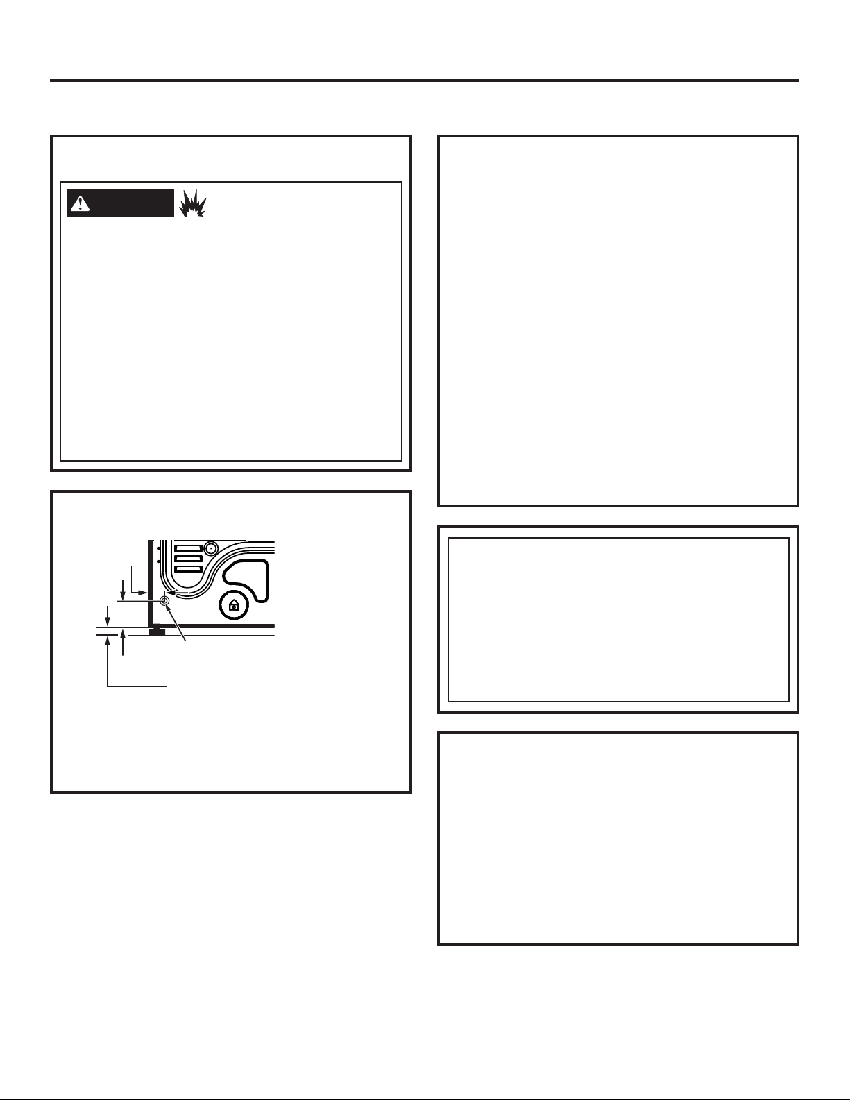
See “Electrical Connection” located in the Installation Instructions for grounding instructions.
To reduce the risk of fire, explosion, electric shock, or injury to persons when using your appliance, follow
basic precautions, including the following:
repair or replace any part of this appliance or attempt any servicing unless specifically
Keep area around the exhaust
to reduce the possibility of slipping
.
.
SAVE THESE INSTRUCTIONS
2
Page 3
GEAppliances.com
ADDITIONAL GAS DRYER WARNINGS
WARNING
- DO NOT store or use gasoline or other flammable vapors and liquids in the vicinity of this or any other appliance.
- WHAT TO DO IF YOU SMELL GAS:
• DO NOT try to light any appliance.
• DO NOT touch any electrical switch; DO NOT use any phone in your building.
• Clear the room, building, or area of any occupants.
• Immediately call your gas supplier from a neighbor’s phone. Follow the gas supplier’s instructions.
• If you cannot reach your gas supplier, call the fire department.
- Installation and service must be performed by a qualified installer, service agency, or the gas supplier.
For your safety, the information in this manual must be followed to minimize the risk of fire or explosion
or to prevent damage, personal injury, or death.
State of California Proposition 65 Warnings:
The California Safe Drinking Water and Toxic Enforcement Act requires the governor of California to publish a list of substances
known to the state to cause cancer, birth defects or other reproductive harm and requires businesses to warn of potential exposure
to such substances.
WARNING
Gas appliances can cause low-level exposure to some of these substances, including benzene, carbon monoxide, formaldehyde and
soot, caused primarily by the incomplete combustion of natural gas or LP fuels. Exposure to these substances can be minimized by
properly venting the dryer to the outdoors.
This product contains one or more chemicals known to the State of California to cause cancer, birth defects or
other reproductive harm.
SAVE THESE INSTRUCTIONS
3
Page 4
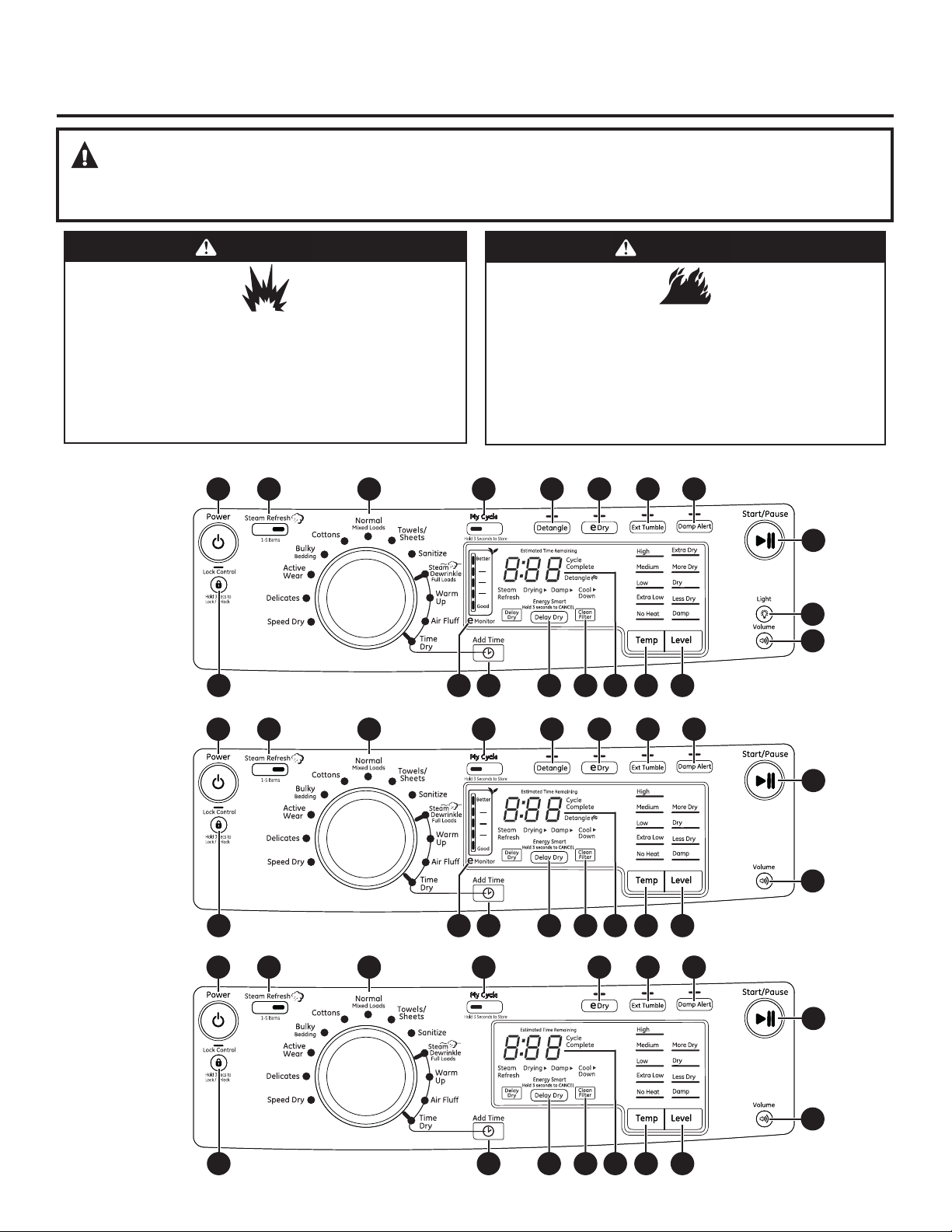
About the dryer control panel.
WARNING!
To reduce the risk of fire, electric shock, or injury to persons, read the IMPORTANT SAFETY INSTRUCTIONS before
operating this appliance.
WARNING
Explosion Hazard
Keep flammable materials and vapors, such as gasoline, away
from dryer.
DO NOT dry anything that has ever had anything flammable on
it (even after washing).
Failure to do so can result in death, explosion, or fire.
Throughout this manual, features and appearance may vary from your model.
Models:
GFDR485
GFDR480
GFDS375
GFDS370
GHDS365
GHDS360
1 8 2 7
No washer can completely remove oil.
Do not dry anything that has ever had any type of oil on it
(including cooking oils).
Items containing foam, rubber, or plastic must be dried on a
clothesline or by using an air dry cycle.
Failure to follow these instructions can result in death or fire.
9 10 11 12
17 13 18 19
WARNING
Fire Hazard
6
14
15
54316
Models:
GFDS265
GFDS260
Models:
GFDS255
GFDS250
4
1 8 2 7
17 13 18 19
1 8 2 7
9 10 11 12
10 11 12
13 18 19
6
15
54316
6
15
54316
Page 5
Control settings.
Quick Start
GEAppliances.com
Press the
1
If the screen is dark, a press
of the Power button will
“wake up” the display.
Select a dry cycle. (Defaults are set
2
for each cycle. These default
settings can be changed. See
Control settings for more
information.)
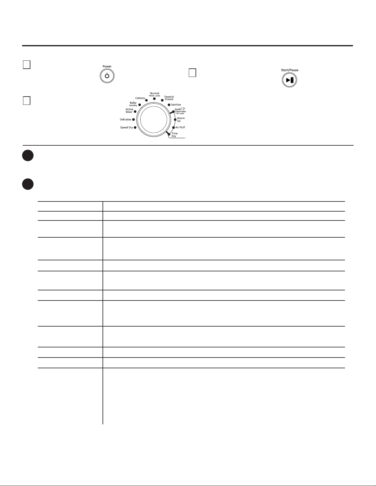
Power
1
Press to “wake up” the display. If the display is active, press to turn the dryer off.
NOTE: Pressing Power does not disconnect the appliance from the power supply.
Dry Cycles
2
The dry cycle controls the length and tumble speed of the drying process. The chart below will help you match the dry
setting with the loads.
Power
button.
Normal/Mixed Loads
Cottons
Bulky/Bedding
Active Wear
Delicates
Press the Start/Pause button.
3
For loads consisting of cottons and poly-blends.
For cottons and most linens.
For large coats, bed spreads, mattress covers, sleeping bags, blankets, comforters, jackets, small
rugs, and similar large and bulky items.
Clothing worn for active sports exercise and some casual wear. Fabrics include new technology
finishes and stretch fibers such as Spandex. Also for clothing labeled Easy Care or Perma Press:
For wrinkle-free and permanent press items.
For lingerie and special-care fabrics.
Speed Dry
Towels/Sheets
Sanitize
Steam Dewrinkle
Full Loads
Warm Up
Air Fluff
Time Dry
For small loads that are needed in a hurry, such as sports or school uniforms. Can also be used if
the previous cycle left some items damp, such as collars or waistbands.
Use for towels OR sheets. It is not recommended to mix towels and sheets in the same load.
Reduces certain types of bacteria by 99.8%, including: Staphylococcus aureus, Pseudomonas
aeruginosa, and Klebsiella pneumoniae. The antibacterial process occurs when high heat is used
during a portion of this drying cycle.
Ideal for loads left in dryer for an extended time.
Provides 10 minutes of warming time to warm up clothes.
Use to tumble items without heat.
Use to set your own dry time. Time Dry is also recommended for small loads. To use:
1. Turn dry cycle dial to Time Dry.
2. Increase the drying time by pressing the Add Time button.
Note: This button only increases the time. When max time is reached, pressing the button
again will reset the counter to the lowest setting.
3. Select the Temp.
4. Close the door.
5. Press Start/Pause.
5
Page 6
Control settings.
3
4
5
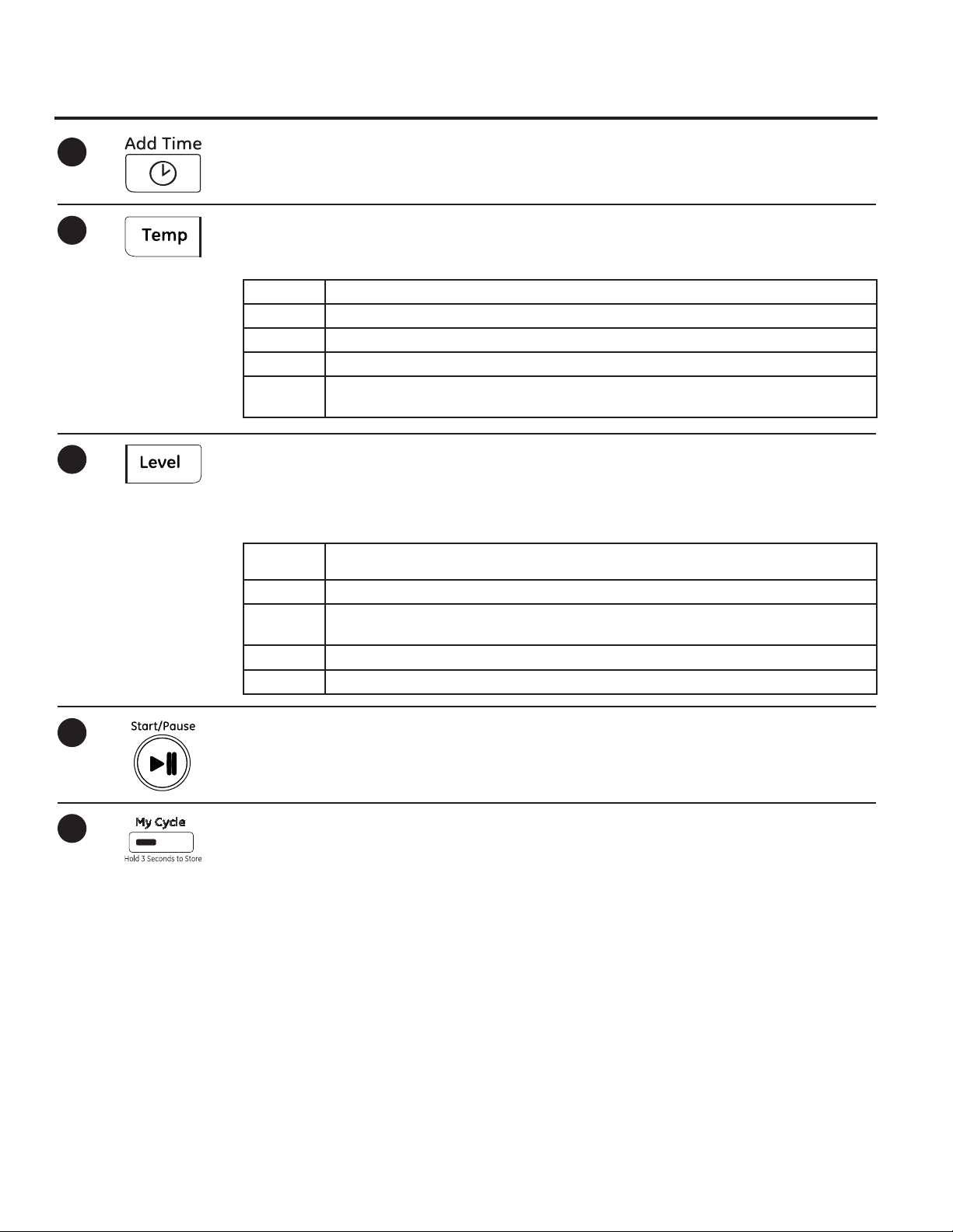
Add Time
Press to add time to the Steam Dewrinkle,
Warm Up, Air Fluff or Time Dry cycles.
Dry Temp
You can change the temperature of your dry
cycle.
High For regular to heavy cottons.
Medium For synthetics, blends and items labeled Permanent Press.
Low For delicates, synthetics and items labeled Tumble Dry Low.
Extra Low For lingerie and special-care fabrics.
No Heat This option may only be used with Air Fluff, in which items are tumbled without
heat.
Sensor Dry Level
The sensor continuously monitors the amount of
moisture in the load. When the moisture in your
clothes reaches your selected dry level, the dryer
will stop.
Extra Dry
(on some models)
More Dry Use for heavy or mixed type of fabrics.
Dry Use for normal dryness level suitable for most loads. This is the preferred cycle for
Less Dry
Damp For leaving items partially damp.
Use for heavy-duty fabrics or items that should be very dry, such as towels.
energy saving.
Use for lighter fabric (ideal for ironing).
NOTE: Sensor dry Level only works with
Cottons, Normal, Active Wear, Delicates,
Speed Dry, Bulky, Towels/Sheets, Sanitize
and Steam Dewrinkle cycles.
6
7
Start/Pause
Press to start a dry cycle. If the dryer is
running, press it once and it will pause the
dryer. Press it again to resume the dry cycle.
My Cycle
Set up your favorite combination of settings
and save them here for one touch recall.
These custom settings can be set while a cycle
is in progress.
To store a My Cycle combination of settings:
1. Select your drying cycle.
2. Change Temp and Level settings to fit your
needs.
3. Select any drying options you want.
4. Press and hold the My Cycle button for 3
seconds to store your selection. A beep will
sound and the button will light up.
To recall your stored My Cycle combination:
Press the MY CYCLE button before drying a
load.
To change your stored My Cycle
combination:
Repeat steps 1–4.
6
Page 7
GEAppliances.com
8
9
10
11
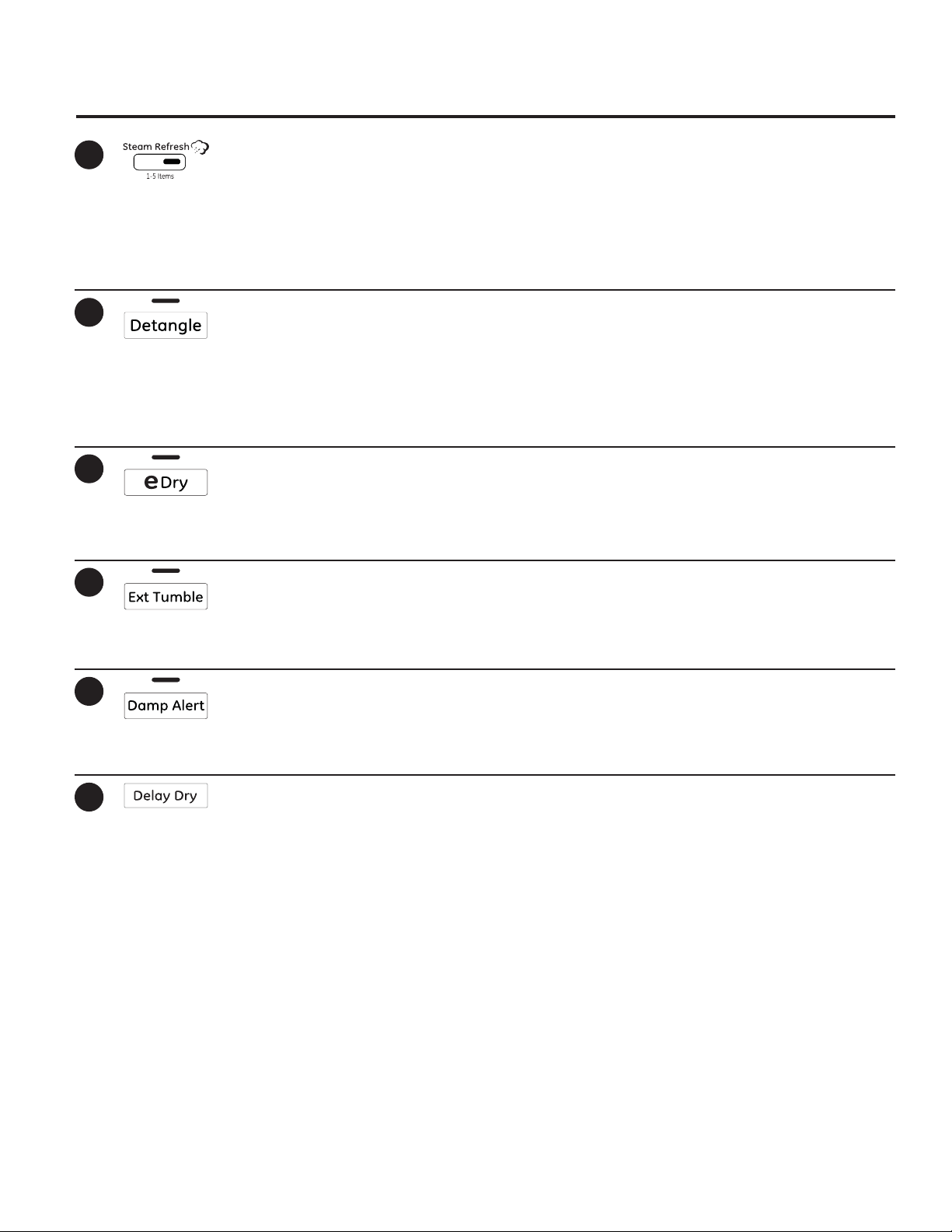
Steam Refresh Cycle
For slightly wrinkled dry garments. Significantly
reduces wrinkles on up to 5 garments. After the
Steam Refresh Cycle, the unit will beep and display
“0:00.” If the unit is not turned off or if the door is
not opened, the dryer will continue to tumble for
30 minutes. At the end of 30 minutes, it will display
“0:00” and the cycle will be complete.
Detangle (on some models)
Activates reverse tumbling to reduce tangling, dry
more evenly, and improve drying times. Typical
loads such as bed and bath mixed loads, where
sheets, towels and pillow cases are laundered
together, benefit from this capability. When the
dryer reverses direction, there will be a slight pause
and sound change. This is normal.
eDry
Reduces the total energy consumption of specific
dryer cycles by adjusting certain heat settings.
NOTE: Cycle times will change when e-Dry is
selected.
Extended Tumble
Minimizes wrinkles by adding approximately 60
minutes of no-heat tumbling after clothes are
dry. The beeper will sound every five minutes as a
reminder to remove the clothes.
NOTE: A single extremely light fabric item may need
to have an additional item included to achieve
optimum results.
This cycle can be used with Cottons, Normal, Active
Wear, Delicates, Speed Dry, Bulky, Towels-Sheets,
Sanitize and Steam Dewrinkle.
The estimated time remaining display will show
“0:00”.
The extended tumble time does not get added to
the cycle time on the display.
12
13
Damp Alert
This option causes the dryer to beep when clothes
have dried to a damp level. Remove items that you
wish to hang dry. The Damp Alert will only beep
when this option is selected.
Delay Dry
Use to delay the start of your dryer.
1. Choose your dry cycle and any options.
2. Press Delay Dry. You can change the delay time
in 1 hour increments, using the Delay Dry button.
3. Press the Start/Pause button to start the
countdown.
Removing clothes and hanging them when they are
damp can reduce the need to iron some items.
NOTE: If the door is opened while the dryer is in
Delay Dry, the countdown time will not restart
unless the door is closed and Start/Pause button
has been pressed again.
7
Page 8
Control settings.
14
15
16
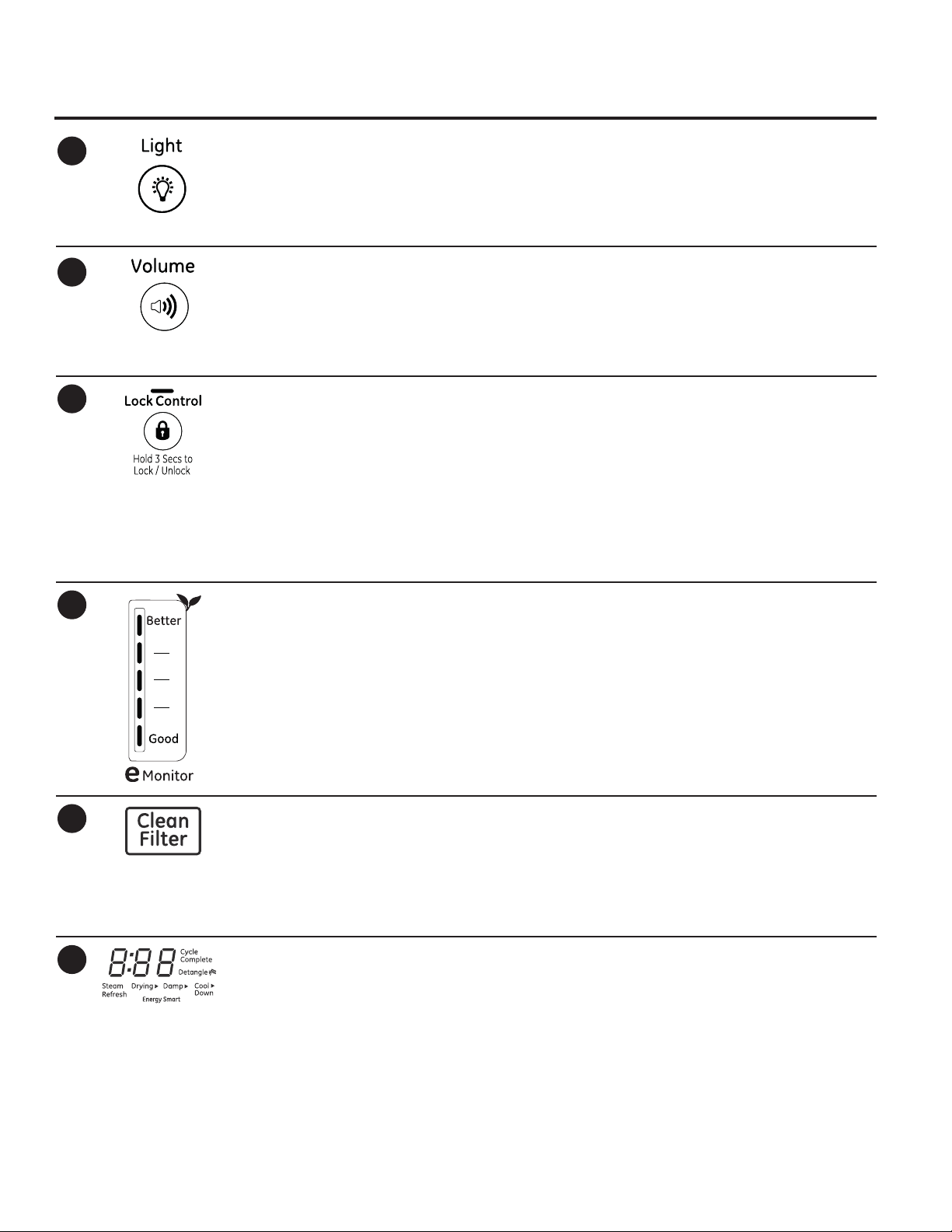
Light (on some models)
Press the button to turn on the light in the
dryer.
Press the button again to turn the light off.
Volume
Alerts you that the cycle is complete. The beeper
will continue to sound every minute for the next
5 minutes, until the clothes have been removed.
The clothes should be removed when the beeper
goes off so wrinkles don’t set in.
Lock Control
You can lock the controls to prevent any
selections from being made. Or you can lock
or unlock the controls after you have started
a cycle.
Children cannot accidentally start the dryer by
touching buttons with this option selected.
To lock the dryer, press and hold the Lock
Control button for 3 seconds.
This only controls the light when the door is
shut.
NOTE: The light will turn off by itself after
one minute when the door is shut.
Press Volume to select low, medium or high
volume, or to turn the beeper off.
To unlock the dryer controls, press and hold
the Lock Control button for 3 seconds.
A sound is made to indicate the lock/unlock
status.
The indicator light above the button will
illuminate when the controls are locked.
NOTE: The Power button can still be used
when the machine is locked.
17
18
19
eMonitor (on some models)
The eMonitor lights display the relative
energy use of your selected cycle and options.
They are provided as an energy guide and
range from Good (1 light) to Better (5 lights).
Cycle (time), dryness level, temperature, and
additional tumble options can increase or
decrease your energy efficiency. Some cycles
will not provide a display.
Clean Filter Message
This message represents only a reminder and
does not always appear when the filter needs
cleaning. The filter should be cleaned after every
drying cycle is complete.
Display
Displays the approximate time remaining until
the end of the cycle.
As the cycle begins, you will see an initial
approximate total cycle time in the display.
This message will disappear after the Start/
Pause button is pressed. Even though you may
have already cleaned the filter (before or after
the Power button has been pressed), the “Clean
Filter” message will still be displayed until the
Start/Pause button is activated.
Then lights will “race” in the display. This
means the dryer is continuously monitoring
the amount of moisture in the load. The lights
will continue until the dryer senses a low level
of moisture in the load. At that point, the dryer
will calculate and display the approximate
time remaining.
8
Page 9
Using the dryer.
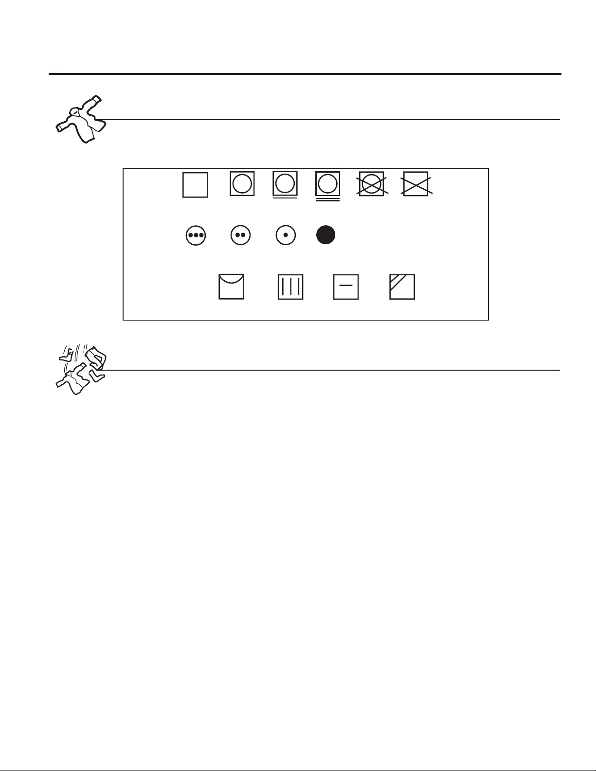
Always follow the fabric manufacturer’s care label when laundering.
Fabric Care Labels
Below are fabric care label “symbols” that affect the clothing you will be laundering.
Dry Labels
Tumble
dry
Heat
setting
Special
instructions
Dry
High
Normal
Medium
Line dry/
hang to dry
Permanent Press/
wrinkle resistant
Low
Drip dry
Gentle/
delicate
No heat/air
Do not tumble dry
Dry flat
Do not dry
(used with
do not wash)
In the shade
GEAppliances.com
Sorting and Loading Hints
As a general rule, if clothes are sorted
properly for the washer, they are sorted
properly for the dryer. Try also to sort items
according to size. For example, do not dry a
sheet with socks or other small items.
Do not add fabric softener sheets once
the load has become warm. They may
cause fabric softener stains. Bounce®
Fabric Conditioner Dryer Sheets have been
approved for use in this dryer when used
in accordance with the manufacturer’s
instructions.
Do not overload. This wastes energy and
causes wrinkling.
9
Page 10
About dryer features.
Rest rear legs on
rear angled ledge
Rest front legs on
front angled ledge
Drying Rack (on some models)
A handy drying rack may be used for drying
delicate items such as washable sweaters.
Place items flat on the drying rack and
block such items as wool sweaters and
delicate fabrics. Dry with low heat.
To install the drying rack, extend the drying
rack into the dryer drum. Rest the front two
legs on the front angled ledge and then
rest the rear two legs on the rear angled
edge.
NOTES:
The drying rack is designed for use with
the Time Dry cycles. Use with sensor
cycles may result in damp items or
extended cycle times.
Do not use this drying rack when there
are other clothes in the dryer, that are
not placed on the rack.
10
Page 11
Care and Cleaning of the Dryer.
GEAppliances.com
The Exterior: Wipe or dust any spills or
washing compounds with a damp cloth.
Dryer control panel and finishes may be
damaged by some laundry pretreatment
soil and stain remover products. Apply these
products away from the dryer. The fabric
may then be washed and dried normally.
Damage to your dryer caused by these
products is not covered by your warranty.
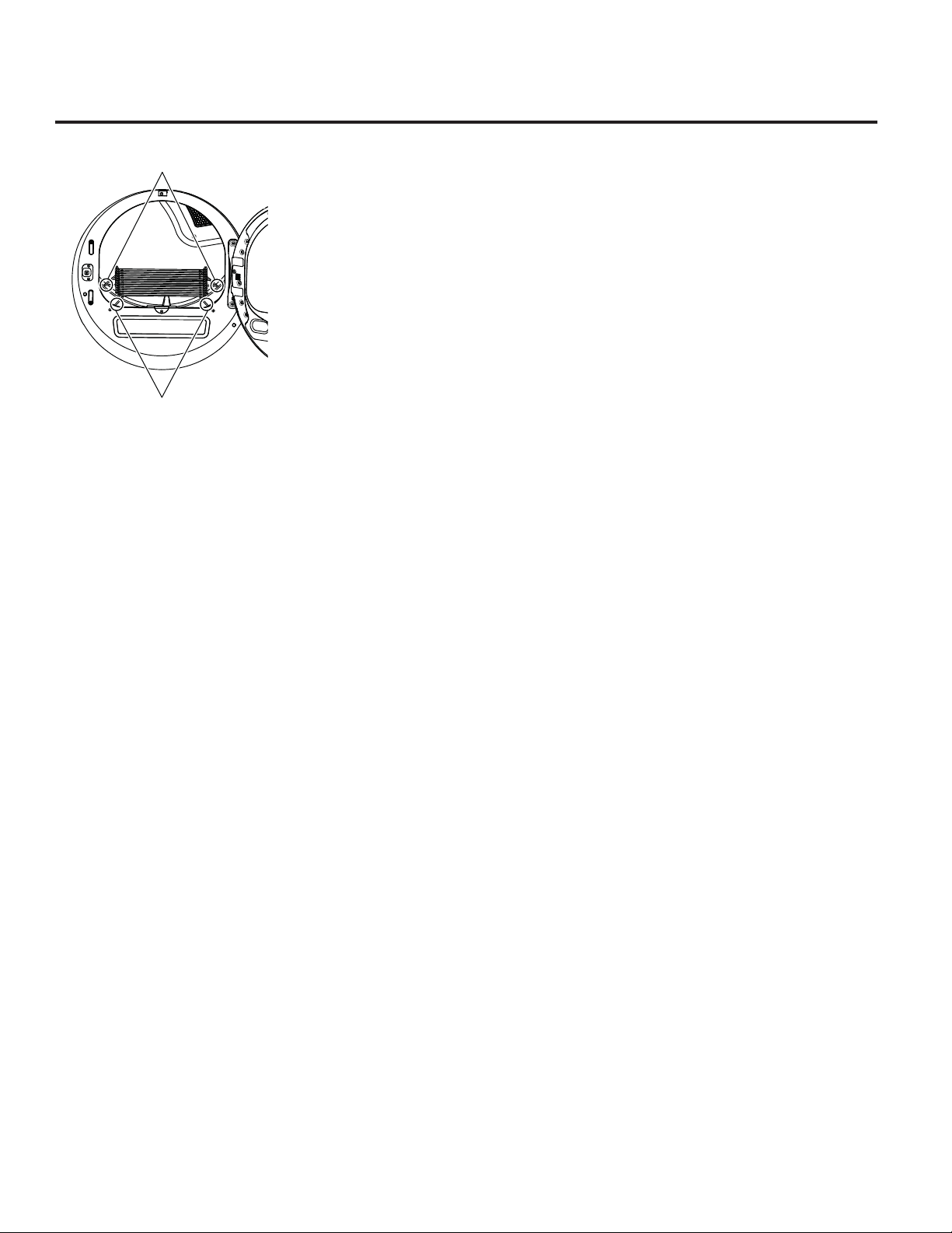
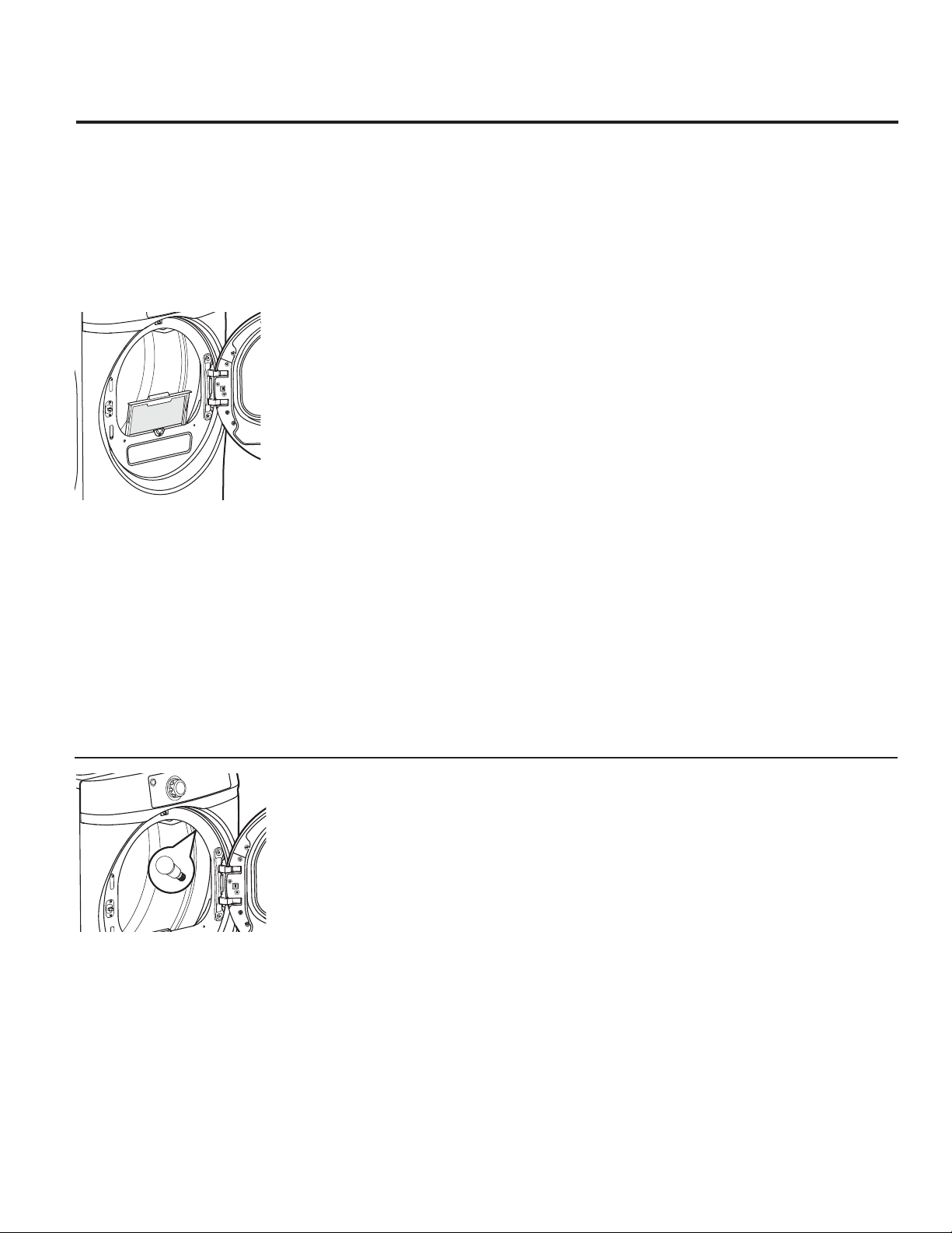
The Lint Filter: Clean the lint filter before
each use.
Pull out the lint filter.
Moisten your fingers and remove the
captured lint. Once clean, slide the filter back
into position. Have a qualified technician
vacuum the lint from the dryer once a year.
NEVER OPERATE
THE DRYER WITHOUT ITS FILTER
IN PLACE.
Stainless Steel: To clean stainless steel
surfaces use a damp cloth with a mild, nonabrasive cleaner suitable for stainless steel
surfaces. Remove the cleaner residue and
then dry with a clean cloth.
Dryer Interior and Duct: The interior of
the appliance and exhaust duct should be
cleaned once a year by qualified service
personnel.
The Exhaust Duct: Inspect and clean the
exhaust ducting at least once a year to
prevent clogging.
A partially clogged exhaust can lengthen the
drying time.
The Exhaust Hood: Check with a mirror that
the inside flaps of the hood move freely when
operating. Make sure that there is no wildlife
(birds, insects, etc.) nesting inside the duct or
hood.
The stainless steel used to make the dryer
drum provides the highest reliability available
in a GE dryer. If the dryer drum should be
scratched or dented during normal use, the
drum will not rust or corrode. These surface
blemishes will not affect the function or
durability of the drum.
Drum Lamp (on models GFDS250, GFDS255, GFDS260 and GFDS265 only)
NOTE: The drum lamp is not consumer
replaceable on models GHDS360, GHDS365,
GFDS370, GFDS375, GFDR480 and GFDR485.
If this light should ever stop working, call for
service.
Before replacing the light bulb, be sure to
unplug the dryer power cord or disconnect
the dryer at the household distribution panel
by removing the fuse or switching off the
circuit breaker. Reach above dryer opening
from inside the drum. Remove the bulb and
replace with the same size bulb.
Drum lamp only (and automatically) turns on
when the dryer door is open.
Order replacement bulb WE4M305 on-line
at GEApplianceParts.com, by phone at
800.626.2002 during normal business hours,
or purchase appliance bulb 7C7 from your
local retailer.
11
Page 12
Installation Dryers
Instructions
Questions? Call 800.GE.CARES (800.432.2737) or visit our Web site at: GEAppliances.com
In Canada, call 1.800.561.3344 or visit www.GEAppliances.ca
This is the safety alert symbol. This symbol alerts you to potential hazards that can kill you or hurt you and others.
All safety messages will follow the safety alert symbol and the word “DANGER”, “WARNING”, or “CAUTION”. These
words are defined as:
DANGER
WARNING
CAUTION
Indicates a hazardous situation which, if not avoided, will result in death or serious injury.
Indicates a hazardous situation which, if not avoided, could result in death or serious injury.
Indicates a hazardous situation which, if not avoided, could result in minor or moderate injury.
BEFORE YOU BEGIN
Read these instructions completely and carefully.
•
IMPORTANT – Save these instructions for local
electrical inspector’s use.
IMPORTANT – Observe all governing codes and
•
ordinances.
•
Install the clothes dryer according to the manufacturer’s
instructions and local codes.
•
Note to Installer – Be sure to leave these instructions
with the Consumer.
•
Note to Consumer – Keep these instructions for future
reference.
•
Clothes dryer installation must be performed by a
qualified installer.
•
This dryer must be exhausted to the outdoors.
•
Before the old dryer is removed from service or
discarded, remove the dryer door.
•
Service information and the wiring diagram are located
in the control console.
•
Do not allow children on or in the appliance. Close
supervision of children is necessary when the appliance
is used near children.
•
Proper installation is the responsibility of the installer.
•
Product failure due to improper installation is not
covered under the Warranty
• Install the dryer where the temperature is above 50°F
for satisfactory operation of the dryer control system.
• Remove and discard existing plastic or metal foil duct
and replace with UL-listed duct.
.
WARNING
• Clothes dryer installation must be performed by a
qualified installer.
•
Install the clothes dryer according to these
instructions and local codes.
•
DO NOT install a clothes dryer with flexible plastic
venting materials. If flexible metal (semi-rigid or
foil-type) duct is installed, it must be UL-listed and
installed in accordance with the instructions found
in “Connecting the Dryer to House Vent” later in
this manual. Flexible vent materials are known to
collapse, be easily crushed and trap lint. These
conditions will obstruct dryer airflow and increase
the risk of fire.
•
DO NOT install or store this appliance in any
location where it could be exposed to water or
weather.
•
To reduce the risk of severe injury or death, follow
all installation instructions.
•
Save these instructions. (Installers: Be sure to leave
these instructions with the customer.)
- Fire Hazard
12
Page 13
Installation Instructions
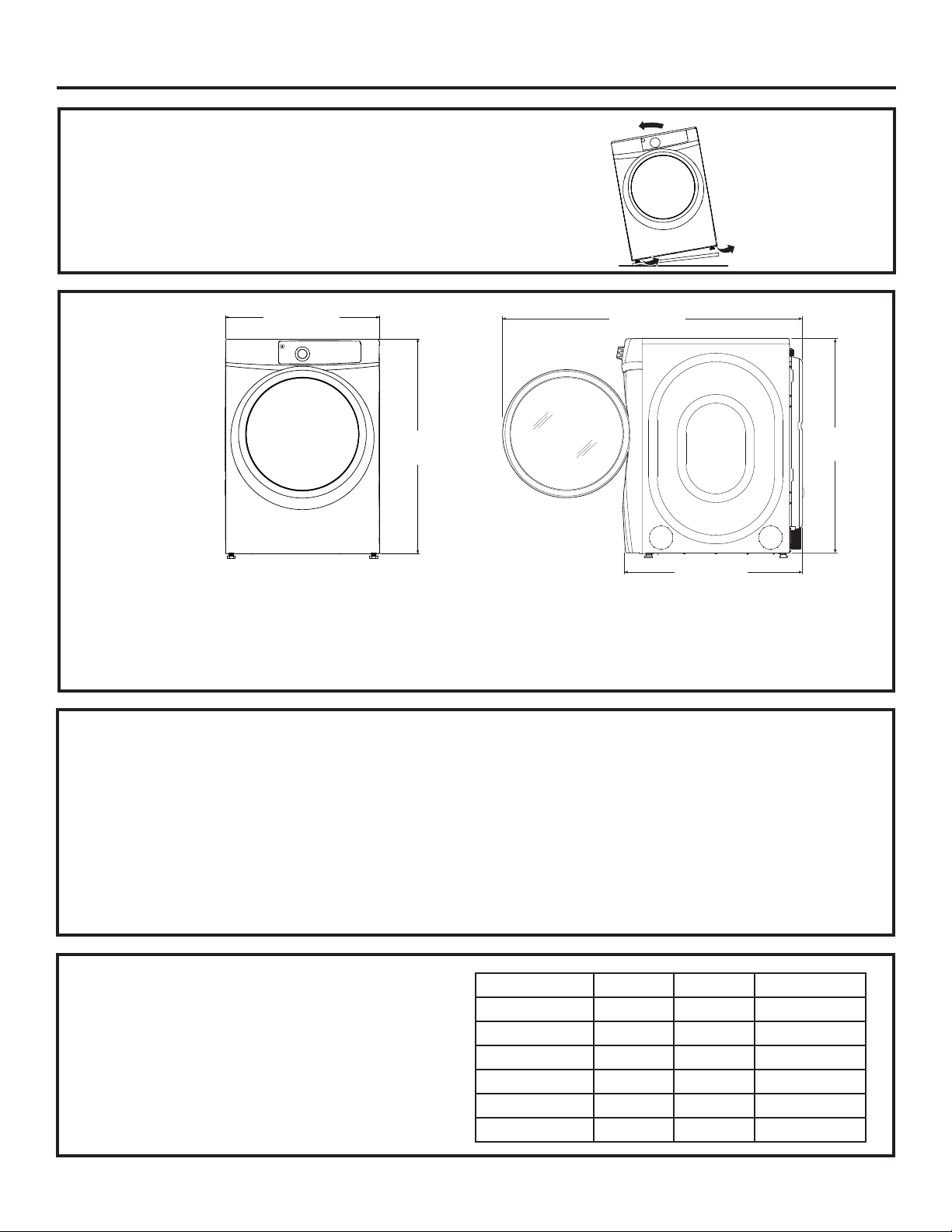
UNPACKING YOUR DRYER
Tilt the dryer sideways and remove the foam
shipping pads by pulling at the sides and breaking
them away from the dryer legs. Be sure to remove all
of the foam pieces around the legs.
Remove the bag containing the literature.
DRYER
DIMENSIONS
28”
(71.12 cm)
39”*
(99 cm)
Front View
*NOTE:
With Legs: 40 1/2” (102.5 cm) - (3/4” (1.9 cm) adjustability)
With Built-In Riser™: 46” (116.9 cm) - (3/4” (1.9 cm) adjustability)
With Optional Pedestal (GFXP1308): 52” (132.1 cm) - (3/4” (1.9 cm) adjustability)
Stacked: 78 1/4” (198.8 cm)
STEAM WATER HOSES:
GE strongly recommends the use of factory specified parts.
These hoses are manufactured and tested to meet GE
specifications.
GE strongly recommends the use of new water supply hoses.
Hoses degrade over time and need to be replaced every 5
years to reduce the risk of hose failures and water damage.
Parts and Accessories
Order on-line at GEApplianceParts.com, 24 hours a day or by
phone at 800.626.2002 during normal business hours.
54 3/8”
(138.1 cm)
39”*
(99 cm)
Side View
32 7/8”
(83.5 cm)
Part Number Accessory
WE25M53 Complete Kit (hoses, Y-adapter
washers) (included)
OR
WE1M847 Long Hose and
WE1M848 Short Hose
PM14X10056 Dryer door opening vent brush
(not included)
WX14X10007 LintEater™ Dryer rotary tube brush
(not included)
POWER CORDS:
GE strongly recommends the use of factory specified parts.
Select the power cord to fit your installation requirements.
Order on-line at GEApplianceParts.com, 24 hours a day or
by phone at 800.626.2002 during normal business hours.
Part Number Type Length Amperage
WX9X2 3-Prong 4 Feet 30
WX9X3 3-Prong 5 Feet 30
WX9X4 3-Prong 6 Feet 30
WX9X18 4-Prong 4 Feet 30
WX9X19 4-Prong 5 Feet 30
WX9X20 4-Prong 6 Feet 30
13
Page 14
Installation Instructions
REQUIREMENTS FOR ALCOVE OR
CLOSET INSTALLATION
WARNING
Keep flammable materials and vapors, such as gasoline,
away from dryer.
Place dryer at least 18” (46 cm) above the floor for a
garage installation.
Failure to do so can result in death, explosion, or fire.
If the dryer is approved for installation in an
•
alcove or closet, it will be stated on a label on the
dryer back.
The dryer MUST be vented to the outdoors.
•
Minimum clearance between dryer cabinet and
•
adjacent walls or other surfaces is:
0” either side
3” front
3” rear
1” top
52” from floor to overhead cabinets
Consideration must be given to provide adequate
•
clearance for installation and service.
Closet ventilation openings required: 2 louvers
•
each 60 square inches (387 square cm), located 3
inches (7.6 cm) from top and bottom of door.
Gas Dryers Only:
No other fuel burning appliance shall be installed
•
in the same closet as a gas dryer.
The dryer must be disconnected from the gas
•
supply piping during pressure testing at pressures
greater than ½ psi (3.5 kPa).
A 1/8 inch NPT minimum plugged tapping,
•
accessible for test gauge connection, must be
installed immediately upstream of the gas supply
connection to the dryer.
- Explosion Hazard
MOBILE OR MANUFACTURED HOME
INSTALLATION
• Installation must conform to the
MANUFACTURED HOME CONSTRUCTION AND
SAFETY STANDARD, TITLE 24, PART 32–80 or
Standard CAN/CSA-Z240 MH, or, when such
standard is not applicable, with AMERICAN
NATIONAL STANDARD FOR MOBILE HOME,
ANSI/NFPA NO. 501B.
The dryer MUST be vented to the outdoors. The
•
exhaust vent must be securely fastened to a
non-combustible portion of the mobile home.
The vent MUST NOT be terminated beneath a
•
mobile or manufactured home.
The vent duct material MUST BE METAL.
•
KIT 14-D346-33 MUST be used to attach the dryer
•
securely to the structure.
The vent MUST NOT be connected to any other
•
duct, vent or chimney.
Do not use sheet metal screws or other
•
fastening devices which extend into the interior
of the exhaust vent.
Provide an opening with a free area of at least
•
25 square inches for introduction of outside air
into the dryer room.
See the sections for electrical connection
•
information.
14
Page 15
Installation Instructions
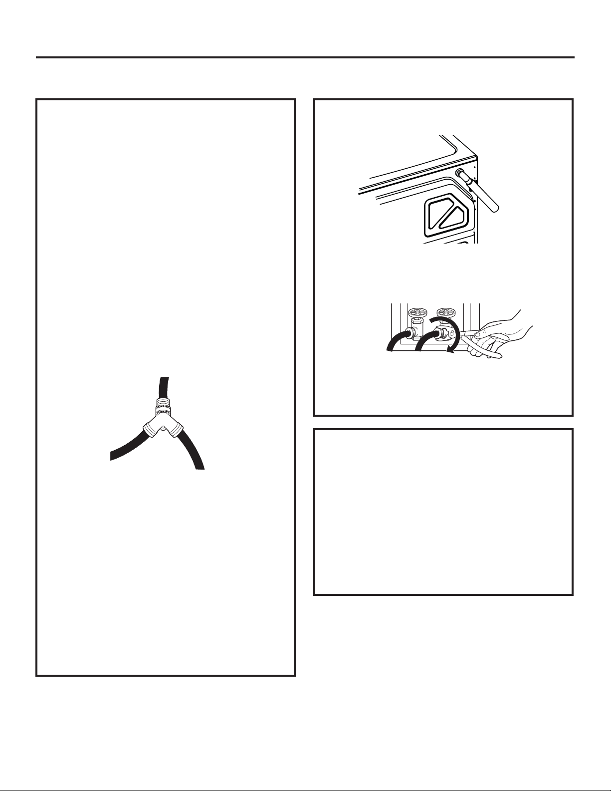
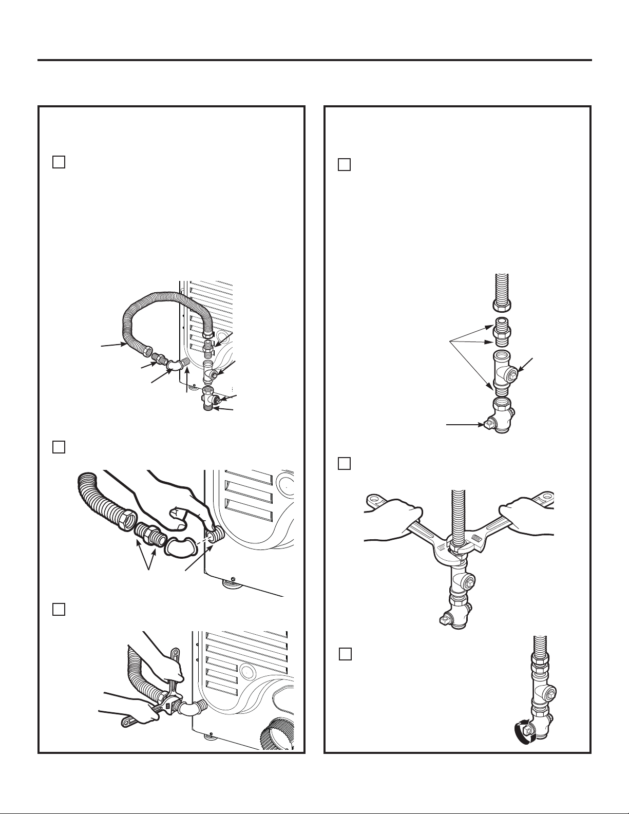
CONNECTING INLET HOSES
CONNECTING INLET HOSES
To produce steam, the dryer must connect to
the cold water supply. Since the washer must
also connect to the cold water, a “Y” connector
is inserted to allow both inlet hoses to make that
connection at the same time.
NOTE: Use the new inlet hoses provided; never use
old hoses.
1. Turn the cold water faucet off. Remove the
washer inlet hose from the washer fill valve
connector (cold).
2. Ensure the rubber flat washer is in place and
screw the female coupling of the short hose
onto the washer fill valve connector. Tighten by
hand until firmly seated.
3. Attach the female end of the ‘’Y’’ connector to
the male coupling of the short hose. Ensure the
rubber flat washer is in place. Tighten by hand
until firmly seated.
CONNECTING INLET HOSES (cont.)
7. Using pliers, tighten all the couplings with an
additional two–thirds turn.
NOTE: Do not overtighten. Damage to the couplings
may result.
8. Turn the water faucet on.
9. Check for leaks around the ‘’Y’’ connector, faucet
and hose couplings.
4. Insert the filter screen in the coupling of the
washer’s inlet hose. If a rubber flat washer is
already in place remove it before installing the
filter screen. Attach this coupling to one male
end of the ‘’Y’’ connector. Tighten by hand until
firmly seated.
5. Ensure the rubber flat washer is in place and
attach the dryer’s long inlet hose to the other
male end of the ‘’Y’’ connector. Tighten by hand
until firmly seated.
6. Ensure the rubber flat washer is in place and
attach the other end of the dryer’s long inlet
hose to the fill valve connector at the top of
the dryer back panel. Tighten by hand until
firmly seated.
WATER SUPPLY REQUIREMENTS
Hot and cold water faucets MUST be installed
within 42 in. (107 cm) of your washer’s water
inlet. The faucets MUST be 3/4 in. (1.9 cm) garden
hose-type so inlet hoses can be connected. Water
pressure MUST be between 10 and 120 pounds
per square inch. Your water department can
advise you of your water pressure.
NOTE: A water softener is recommended to reduce
buildup of scale inside the steam generator if the
home water supply is very hard.
15
Page 16
Installation Instructions
CONNECTING A GAS DRYER (skip for electric dryers)
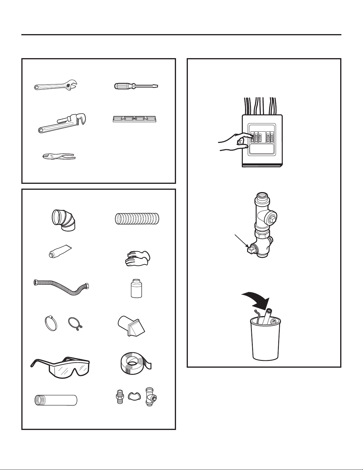
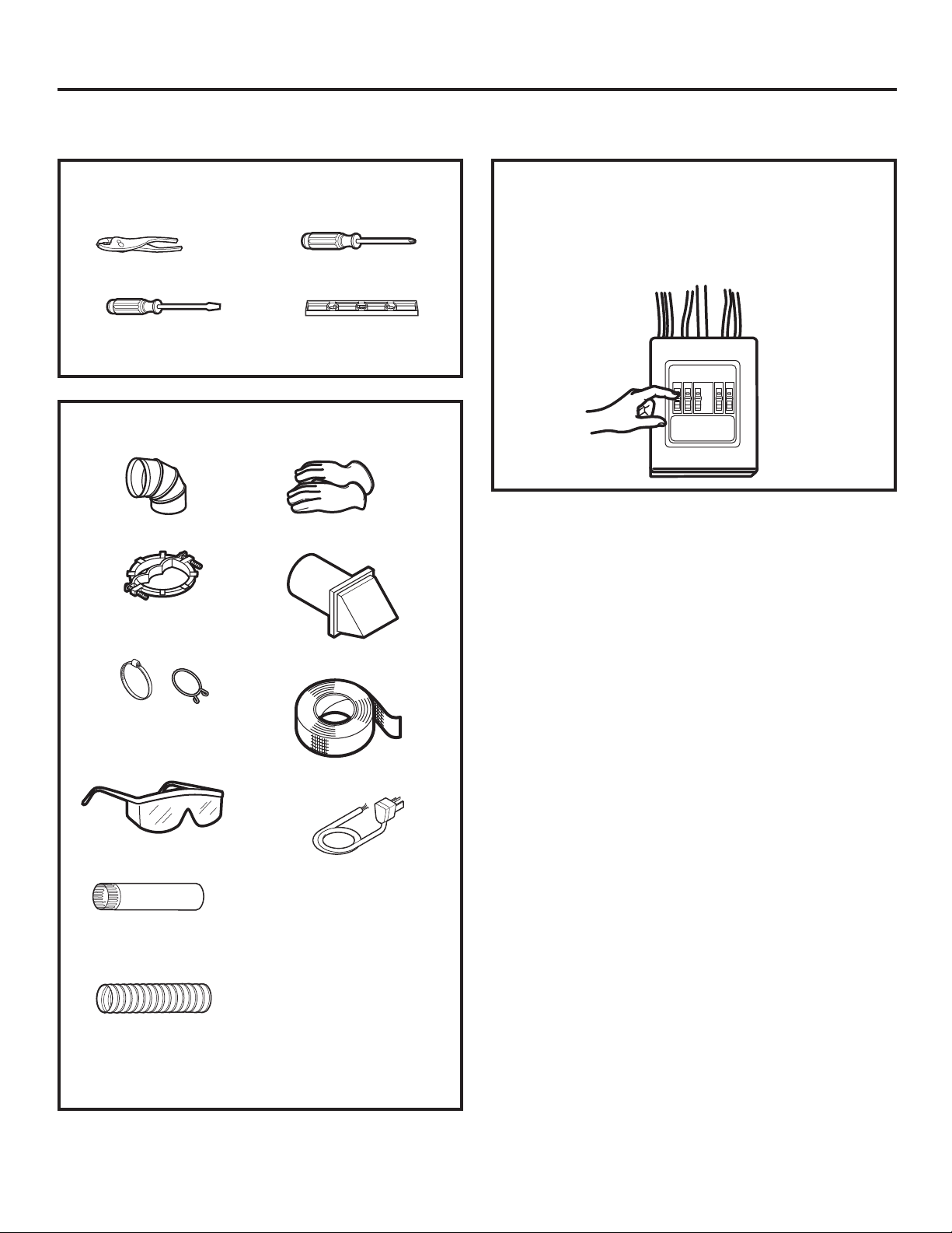
TOOLS YOU WILL NEED
Flat-blade
10” Adjustable
wrenches (2)
8” Pipe wrench
Slip-joint pliers
screwdriver
Level
MATERIALS YOU WILL NEED
4” dia. metal elbow
4” dia., UL-listed
flexible metal duct (if
needed)
Before beginning the installation, turn off
the circuit breaker(s) or remove the dryer’s circuit
fuse(s) at the electrical box. Be sure the dryer cord
is unplugged from the wall.
Turn the dryer’s gas shut-off valve in the supply
line to the OFF position.
Shut-off
Valve
Pipe compound or
PTFE tape
Flexible gas line
connector
Duct clamps (2) or
Spring clamps (2)
Safety glasses
4” dia. metal duct
(recommended)
Gloves
Soap solution for
leak detection
Exhaust hood
Duct tape
Gas pipe adapters (2),
elbow and pipe plug
Disconnect and discard old flexible gas connector
and ducting material.
16
Page 17
Installation Instructions
GAS REQUIREMENTS
WARNING
• Use a new CSA International approved flexible
gas supply line. Never reuse old flexible
connectors.
• Install a shut-off valve.
• Securely tighten all gas connections.
• If connected to LP gas, have a qualified person
make sure gas pressure does not exceed 13”
water column.
• Examples of a qualified person include: licensed
heating personnel, authorized gas company
personnel, and authorized service personnel.
• Failure to do so can result in death, explosion,
or fire.
- Explosion Hazard
DRYER GAS SUPPLY CONNECTION
1 19ø32”
(4.05 cm)
3/8” NPT MALE THREAD GAS SUPPLY
47ø16” (11.27 cm)
NOTE: Add to vertical dimension
the distance between cabinet
bottom to floor.
GAS SUPPLY
• A 1/8” National Pipe Taper thread plugged
tapping, accessible for test gauge connection,
must be installed immediately upstream of the
gas supply connection to the dryer. Contact
your local gas utility should you have questions
on the installation of the plugged tapping.
Supply line is to be 1/2” rigid pipe and equipped
•
with an accessible shutoff within 6 feet of, and
in the same room with, the dryer.
Use pipe thread compound appropriate for
•
natural or LP gas or use PTFE tape.
Connect flexible metal connector to dryer and
•
gas supply.
The installation must conform with local codes,
•
or in the absence of local codes, with the
National Fuel Gas Code, ANSI Z223.1/NFPA 54,
or the Natural Gas and Propane Installation
Code, CSA B149.1.
IN THE COMMONWEALTH OF
MASSACHUSETTS
• This product must be installed by a licensed
plumber or gas fitter.
When using ball-type gas shut-off valves, they
•
shall be the T-handle type.
A flexible gas connector, when used, must not
•
exceed 3 feet.
You must use with this dryer a flexible metal
connector (listed connector ANSI Z21.24 / CSA 6.10).
The length of the connect shall not exceed 3 ft.
ADJUSTING FOR ELEVATION
• Gas clothes dryers input ratings are based on
sea level operation and need not be adjusted
for operation at or below 2000 ft. elevation. For
operation at elevations above 2000 ft., input
ratings should be reduced at a rate of 4 percent
for each 1000 ft. above sea level.
Installation must conform to local codes and
•
ordinances or, in their absence, the NATIONAL
FUEL GAS CODE, ANSI Z223.
17
Page 18
Installation Instructions
CONNECTING A GAS DRYER (cont.)
CONNECTING THE DRYER TO THE GAS
SUPPLY
Install a female 3/8” NPT elbow at the end of the
A
dryer gas inlet.
Install a 3/8” flare union adapter to the female
elbow.
IMPORTANT: Use a pipe wrench to securely hold
on to the end of the dryer gas inlet to prevent
twisting the inlet.
NOTE: Apply pipe compound or PTFE tape to the
threads of the adapter and dryer gas inlet.
New Metal
Flexible Gas
Line Connector
Adapter
Elbow
Items not supplied
Attach the flexible metal gas line connector to
B
3/8” NPT
the adapter.
Adapter
1/8” NPT
Pipe Plug for
Checking Gas
Inlet Pressure
Shut-Off Valve
Pipe size at
least 1/2”
CONNECTING THE DRYER TO THE GAS
SUPPLY (cont.)
Install a 1/8” NPT plugged tapping to the dryer
D
gas line shut-off valve for checking gas inlet
pressure.
Install a flare union adapter to the plugged
tapping.
NOTE: Apply pipe compound or PTFE tape
to the threads of the adapter and plugged
tapping.
Apply pipe compound
or PTFE tape to all
male threads.
Shut-Off
Valve
Tighten all connections, using two adjustable
E
wrenches. Do not overtighten.
Plugged
Tapping
Apply pipe compound to the
adapter and dryer gas inlet.
Tighten the flexible gas line connection, using
C
two adjustable wrenches.
18
Open the gas shut-off valve.
F
Page 19
Installation Instructions
TEST FOR LEAKS
Never use an open flame to test for gas leaks.
Check all connections for leaks with soapy solution
or equivalent.
Apply a soap solution. The leak test solution must
not contain ammonia, which could cause damage
to the brass fittings.
If leaks are found, close the valve, retighten the
joint and repeat the soap test.
Open Gas
Valve
ELECTRICAL CONNECTION
INFORMATION FOR GAS DRYERS (cont.)
The dryer must be electrically grounded in
accordance with local codes, or in the absence of
local codes, with the National Electrical Code, ANSI/
NFPA 70 or Canadian Electrical Code, CSA C22.1
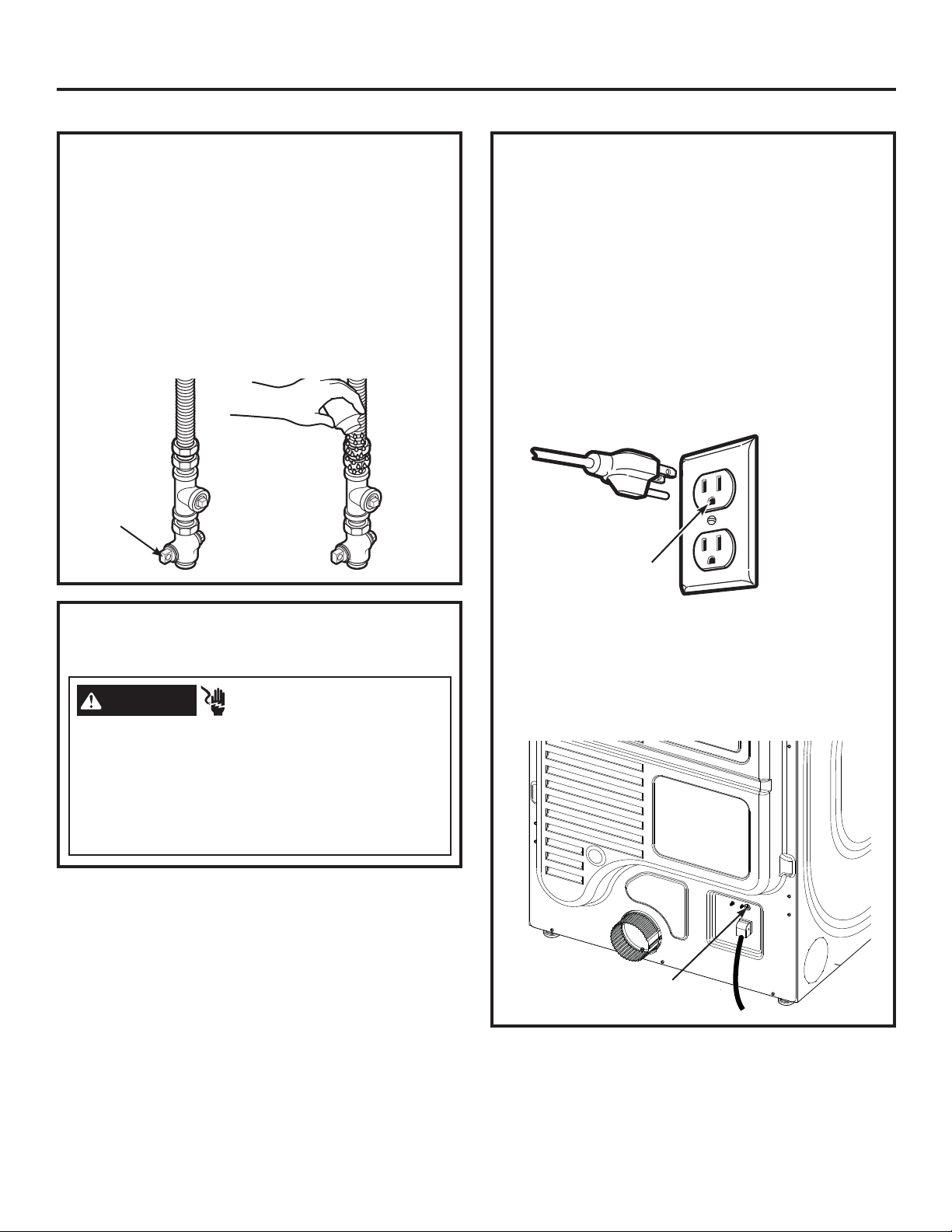
This appliance must be supplied with 120V, 60Hz, and
be connected to a properly grounded branch circuit
protected by a 15 or 20 amp circuit breaker or time
delay fuse. If electrical supply provided does not meet
these requirements, it is the owner’s responsibility to
have a licensed electrician install a properly grounded
3-prong outlet.
Ensure proper
ground exists
before use.
ELECTRICAL CONNECTION
INFORMATION FOR GAS DRYERS
WARNING
Plug into a grounded 3 prong outlet.
DO NOT remove ground prong.
DO NOT use an adapter.
DO NOT use an extension cord.
Failure to do so can result in death, fire or electrical
shock.
- Electrical Shock Hazard
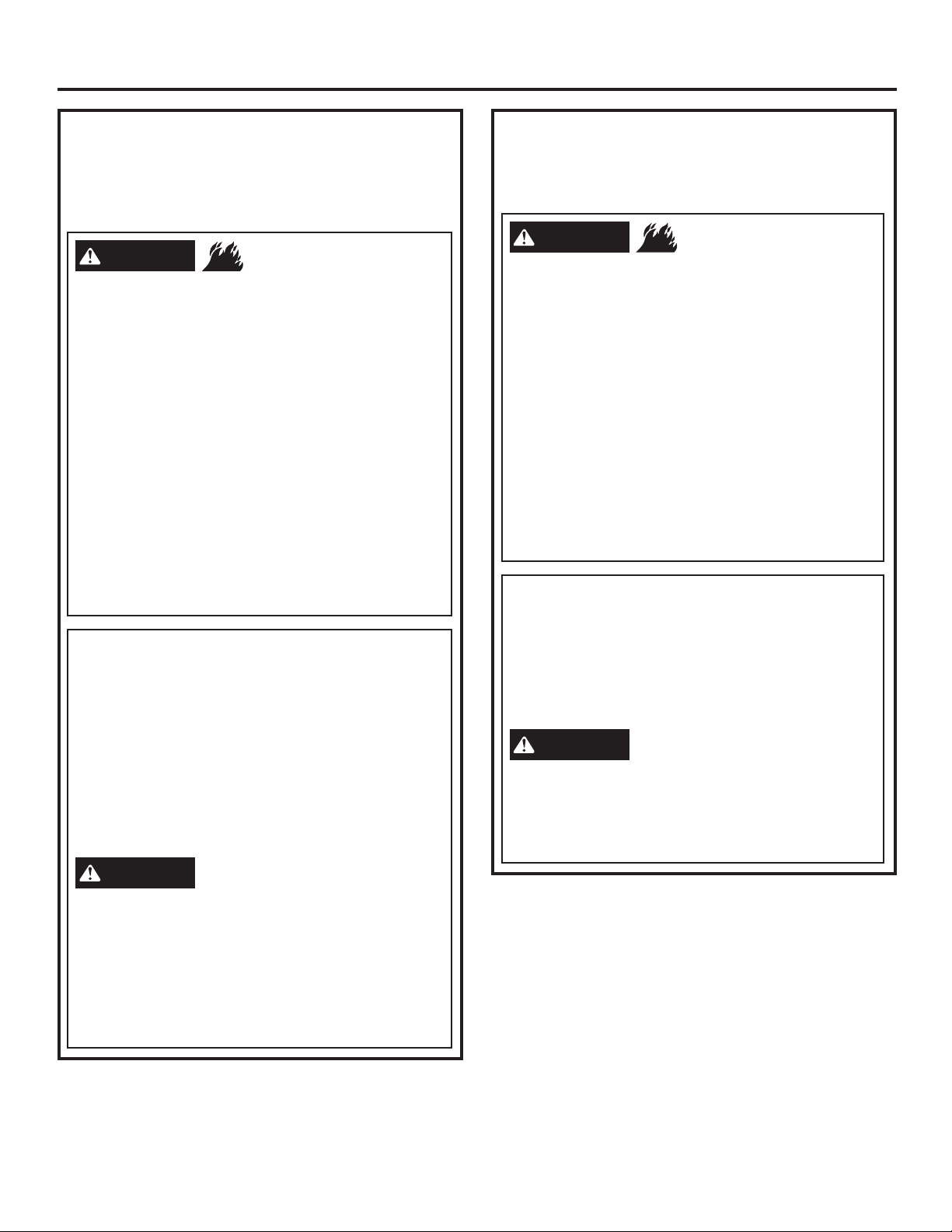
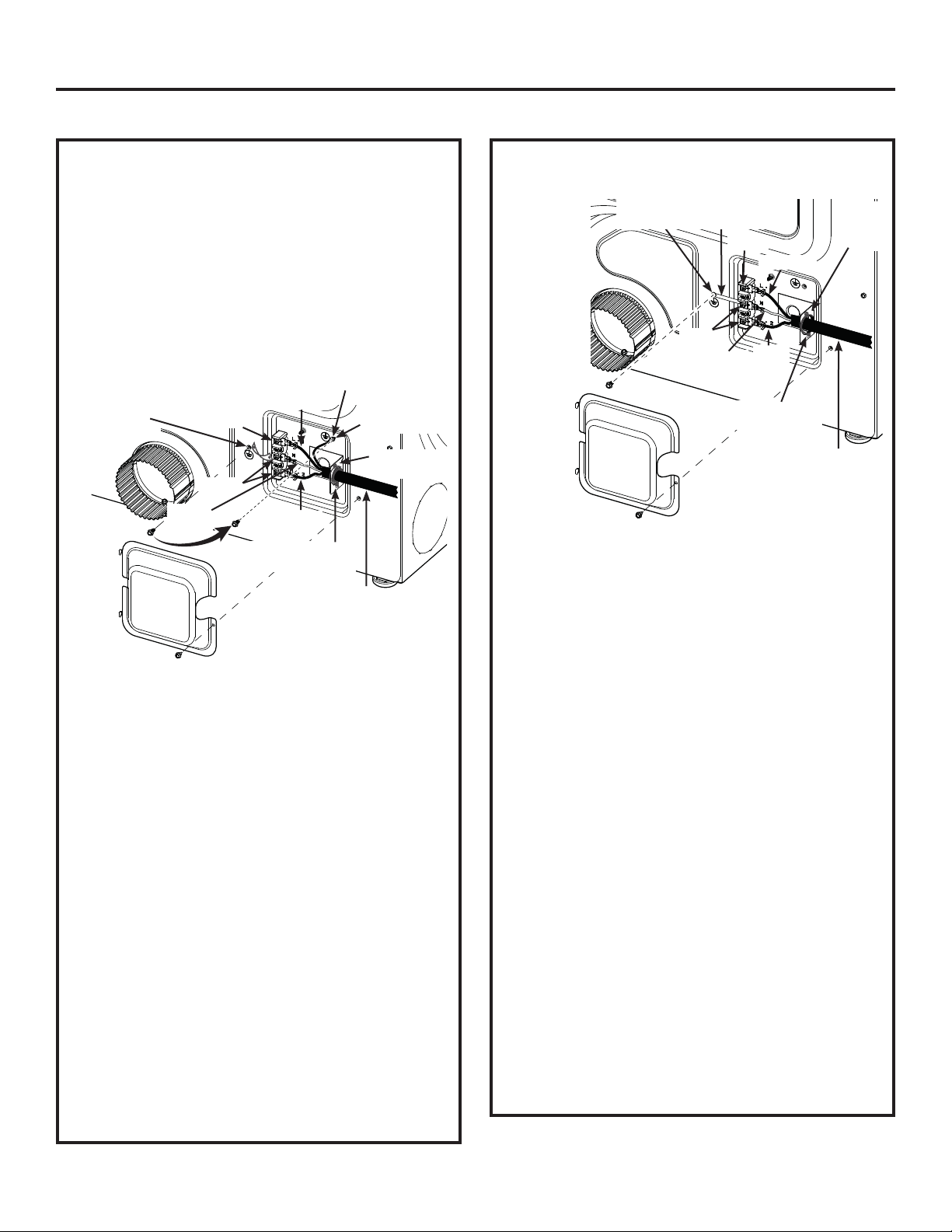
If local codes permit an external ground wire (not
provided) may be added by attaching to the green
ground screw on the rear of the dryer, and to a
grounded metal cold water pipe or other established
ground.
Ground
Screw
19
Page 20
Installation Instructions
CONNECTING AN ELECTRIC DRYER (skip for gas dryers)
TOOLS YOU WILL NEED
Slip-joint pliers
Flat-blade crewdriver
Phillips screwdriver
Level
MATERIALS YOU WILL NEED
4” dia. metal elbow
3/4” strain relief
(UL recognized)
Gloves
Exhaust hood
Before making the electrical connection, turn off
the circuit breaker(s) or remove the dryer’s circuit
fuse(s) at the electrical box. Be sure the dryer cord
is unplugged from the wall.
NEVER LEAVE THE
ACCESS COVER OFF THE TERMINAL BLOCK.
4”duct
clamps (2) or
4”spring clamps (2)
Safety glasses
4” dia. metal duct
(recommended)
4” dia., UL-listed
flexible metal duct (if
needed)
Duct tape
Dryer power cord kit
(not provided with
dryer)
UL rated 120/240V,
30A with 3 or 4 prongs.
Identify the plug type
as per the house
receptacle before
purchasing line cord.
20
Page 21
Installation Instructions
ELECTRICAL CONNECTION
INFORMATION FOR ELECTRIC DRYERS
For electrical connections using a
power cord:
WARNING
Use a new UL-listed 240V 30 amp dryer power supply
cord with closed ring terminals or spade terminals with
upturned ends.
Use a UL-listed strain relief.
Disconnect power before making electrical
connections.
Connect neutral wire (white or center wire) to center
terminal.
Ground wire (green or bare wire) must be connected to
green ground connector.
Connect remaining two supply wires to remaining two
terminals.
Securely tighten all electrical connections.
Replace the terminal block cover.
Failure to do so can result in death, fire or electrical
shock.
- Fire Hazard
GROUNDING INSTRUCTIONS
For a grounded, cord-connected dryer: This dryer
must be grounded. In the event of a malfunction
or breakdown, grounding will reduce the risk
of electric shock by providing a path of least
resistance for electric current. This dryer uses a
cord having an equipment-grounding conductor
and a grounding plug. The plug must be plugged
into an appropriate outlet that is properly installed
and grounded in accordance with all local codes
and ordinances.
WARNING
can result in a risk of electrical shock. Check with a
qualified electrician, or service representative or
personnel, if you are in doubt as to whether the
appliance is properly grounded. DO NOT modify the
plug on the power supply cord. If it will not fit the
outlet, have a proper outlet installed by a qualified
electrician.
SAVE THESE INSTRUCTIONS
Improper connection of the
equipment-grounding conductor
ELECTRICAL CONNECTION
INFORMATION FOR ELECTRIC DRYERS
For direct wire connections:
WARNING
Use 10 gauge copper wire.
Use a UL-listed strain relief.
Disconnect power before making electrical
connections.
Connect neutral wire (white or center wire) to center
terminal.
Ground wire (green or bare wire) must be connected to
green ground connector.
Connect remaining two supply wires to remaining two
terminals.
Securely tighten all electrical connections.
Replace the terminal block cover.
Failure to do so can result in death, fire or electrical
shock.
- Fire Hazard
GROUNDING INSTRUCTIONS
For a permanently connected dryer: This
dryer must be connected to a grounded metal,
permanent wiring system, or an equipmentgrounding conductor must be run with the circuit
conductors and connected to the equipmentgrounding terminal on the appliance.
WARNING
can result in a risk of electrical shock. Check with a
qualified electrician, or service representative or
personnel, if you are in doubt as to whether the
appliance is properly grounded.
SAVE THESE INSTRUCTIONS
Improper connection of the
equipment-grounding conductor
21
Page 22
Installation Instructions
CONNECTING AN ELECTRIC DRYER (cont.)
CONNECTING DRYER USING 4-WIRE
CONNECTION (MUST BE USED FOR
MOBILE HOME INSTALLATION)
NOTE: Since January 1, 1996, the National Electrical
Code requires that new constructions use a 4-wire
connection to an electric dryer. A 4-wire cord must
also be used where local codes do not permit
grounding through the neutral.
3-wire connection is NOT for use on new
construction.
Remove ground
strap and
discard. Keep
green ground
screw
Cover
Turn off the circuit breaker(s) (30 amp) or remove
1.
Screw
Screws
Neutral
(white)
Hot Wire
Hot Wire
3/4” UL Recognized
Strain Relief
4 #10 AWG minimum copper
conductors or 120/240V 30A
power supply cord kit marked
for use with dryers and provided
with closed loop or spade
terminals with upturned ends
(not supplied)
the dryer’s circuit fuse at the electrical box.
Be sure the dryer cord is unplugged from the wall
2.
receptacle.
Remove the power cord cover located at the
3.
lower back.
Remove and discard ground strap. Keep the
4.
green ground screw for Step 7.
Install 3/4 in. UL-recognized strain relief to power
5.
cord entry hole. Bring power cord through strain
relief.
Connect power cord as follows:
6.
A. Connect the 2 hot lines to the outer screws of
the terminal block (marked L1 and L2).
B. Connect the neutral (white) line to the center of
the terminal block (marked N).
Attach ground wire of power cord with the green
7.
ground screw (hole above strain relief bracket).
Tighten all terminal block screws (3) securely.
Properly secure power cord to strain relief.
8.
Reinstall the cover.
9.
NEVER LEAVE THE COVER OFF OF THE TERMINAL
BLOCK.
Relocate green
ground screw here
Green Wire
Strain Relief
Bracket
CONNECTING DRYER USING 3-WIRE
CONNECTION
If required,
by local code,
install external
ground (not
provided) to
grounded metal,
cold water
pipe, or other
established
ground
determined
by a qualified
electrician.
Green Ground
Screw
Cover
3-wire Connection
Not for use in Canada.
DO NOT use for Mobile Home Installations.
NOT for use on new construction.
NOT for use on recreational vehicles.
NOT for use in areas where local codes prohibit
grounding through the neutral conduction.
Turn off the circuit breaker(s) (30 amp) or remove
1.
the dryer’s circuit fuse at the electrical box.
Be sure the dryer cord is unplugged from the wall
2.
receptacle.
Remove the power cord cover located at the
3.
lower back.
Install 3/4-in. UL-recognized strain relief to power
4.
cord entry hole. Bring power cord through strain
relief.
Connect power cord as follows:
5.
A. Connect the 2 hot lines to the outer screws of
the terminal block (marked L1 and L2).
B. Connect the neutral (white) line to the center of
the terminal block (marked N).
Be sure ground strap is connected to neutral
6.
(center) terminal of block and to green ground
screw on cabinet rear. Tighten all terminal block
screws (3) securely.
Properly secure power cord to strain relief.
7.
Reinstall the cover.
8.
NEVER LEAVE THE COVER OFF OF THE TERMINAL
BLOCK.
Ground
Strap
Screw
Hot Wire
Screws
Neutral
(white)
3/4” UL Recognized
Strain Relief
3 #10 AWG minimum copper
conductors or 120/240V 30A
power supply cord kit marked for
use with dryers and provided with
closed loop or spade terminals
with upturned ends (not supplied)
Hot
Wire
Strain
Relief
Bracket
22
Page 23
Installation Instructions
EXHAUSTING THE DRYER
WARNING
This dryer MUST be vented to the outdoors.
Use only 4” rigid metal ducting for the home
exhaust duct.
Use only 4” rigid metal or UL-listed dryer transition
duct to connect the dryer to the home exhaust.
DO NOT use a plastic vent.
DO NOT exhaust into a chimney, kitchen exhaust,
gas vent, wall, ceiling, attic, crawl space, or
concealed space of a building.
DO NOT install a screen in or over the exhaust duct.
DO NOT use duct longer than specified in the
exhaust length table.
Failure to follow these instructions can result in
death or fire.
- Fire Hazard
EXHAUST SYSTEM CHECKLIST
HOOD OR WALL CAP
•
Terminate in a manner to prevent back drafts or entry
of birds or other wildlife.
•
Termination should present minimal resistance to
the exhaust airflow and should require little or no
maintenance to prevent clogging.
•
Wall caps must be installed at least 12” above ground
level or any other obstruction with the opening
pointed down.
•
Never vent the dryer out of the roof.
SEPARATION OF TURNS
•
For best performance, separate all turns by at least
4 ft. of straight duct, including distance between last
turn and dampened wall cap.
SEALING OF JOINTS
•
All joints should be tight to avoid leaks. The male end
of each section of duct must point away from the
dryer.
•
Duct joints should be made air- and moisture-tight
by wrapping the overlapped joints with duct tape or
aluminum tape.
•
Do not assemble ductwork with any fasteners
that extend into the duct. These fasteners can
accumulate lint, creating a potential fire hazard.
• Horizontal runs should slope down towards the
outdoors 1/4” per foot.
•
Provide an access for inspection and cleaning of
the exhaust system, especially at turns and joints.
Exhaust system shall be inspected and cleaned at
least once a year.
INSULATION
•
Ductwork that runs through an unheated area or is
near air conditioning should be insulated to reduce
condensation and lint buildup.
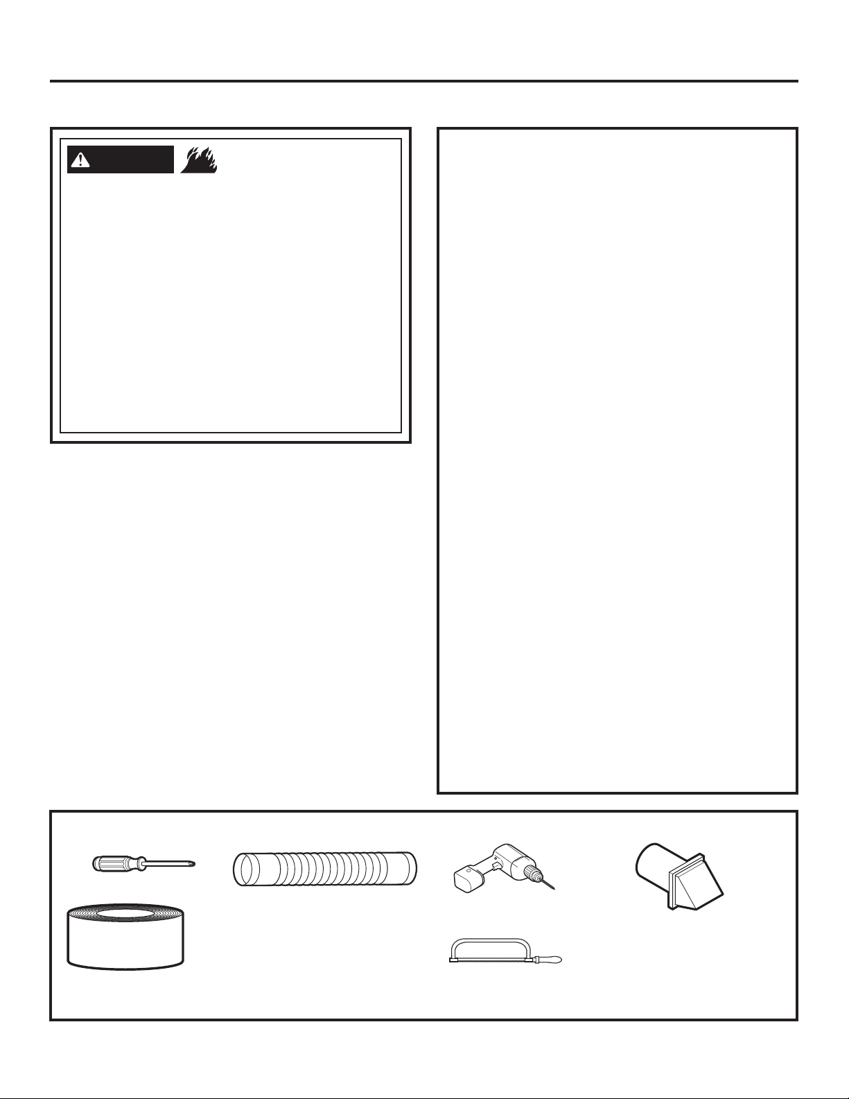
TOOLS AND MATERIALS YOU WILL NEED TO INSTALL EXHAUST DUCT
Phillips-head screwdriver
Rigid or UL-listed
Duct tape or duct
clamp
flexible metal 4” (10.2
cm) duct
Drill with 1/8” drill bit
(for bottom venting)
Hacksaw
23
Vent hood
Page 24
Installation Instructions
EXHAUSTING THE DRYER (cont.)
CONNECTING THE DRYER TO HOUSE
VENT
RIGID METAL TRANSITION DUCT
For best drying performance, a rigid metal transition
•
duct is recommended.
Rigid metal transition ducts reduce the risk of crushing
•
and kinking.
UL-LISTED FLEXIBLE METAL (SEMI-RIGID) TRANSITION
DUCT
•
If rigid metal duct cannot be used, then UL-listed
flexible metal (semi-rigid) ducting can be used (Kit
WX08X10077).
Never install flexible metal duct in walls, ceilings, floors
•
or other enclosed spaces.
Total length of flexible metal duct should not exceed 7’
•
9” (2.4 m).
For many applications, installing elbows at both
•
the dryer and the wall is highly recommended (see
illustrations at right). Elbows allow the dryer to sit
close to the wall without kinking and/or crushing the
transition duct, maximizing drying performance.
Avoid resting the duct on sharp objects.
•
UL-LISTED FLEXIBLE METAL (FOIL-TYPE) TRANSITION
DUCT
•
In special installations, it may be necessary to connect
the dryer to the house vent using a flexible metal
(foil-type) duct. A UL-listed flexible metal (foil-type) duct
may be used ONLY in installations where rigid metal or
flexible metal (semi-rigid) ducting cannot be used AND
where a 4” diameter can be maintained throughout
the entire length of the transition duct.
In Canada and the United States, only the flexible
•
metal (foil-type) ducts that comply with the “Outline for
Clothes Dryer Transition Duct Subject 2158A” shall be
used.
Never install flexible metal duct in walls, ceilings, floors
•
or other enclosed spaces.
Total length of flexible metal duct should not exceed 7’
•
9” (2.4 m).
Avoid resting the duct on sharp objects.
•
For best drying performance:
•
1. Slide one end of the duct over the clothes dryer
outlet pipe.
2. Secure the duct with a clamp.
3. With the dryer in its permanent position, extend
”
the duct to its full length. Allow 2
overlap the exhaust pipe. Cut off and remove
excess duct. Keep the duct as straight as
possible for maximum airflow.
4. Secure the duct to the exhaust pipe with the
other clamp.
of duct to
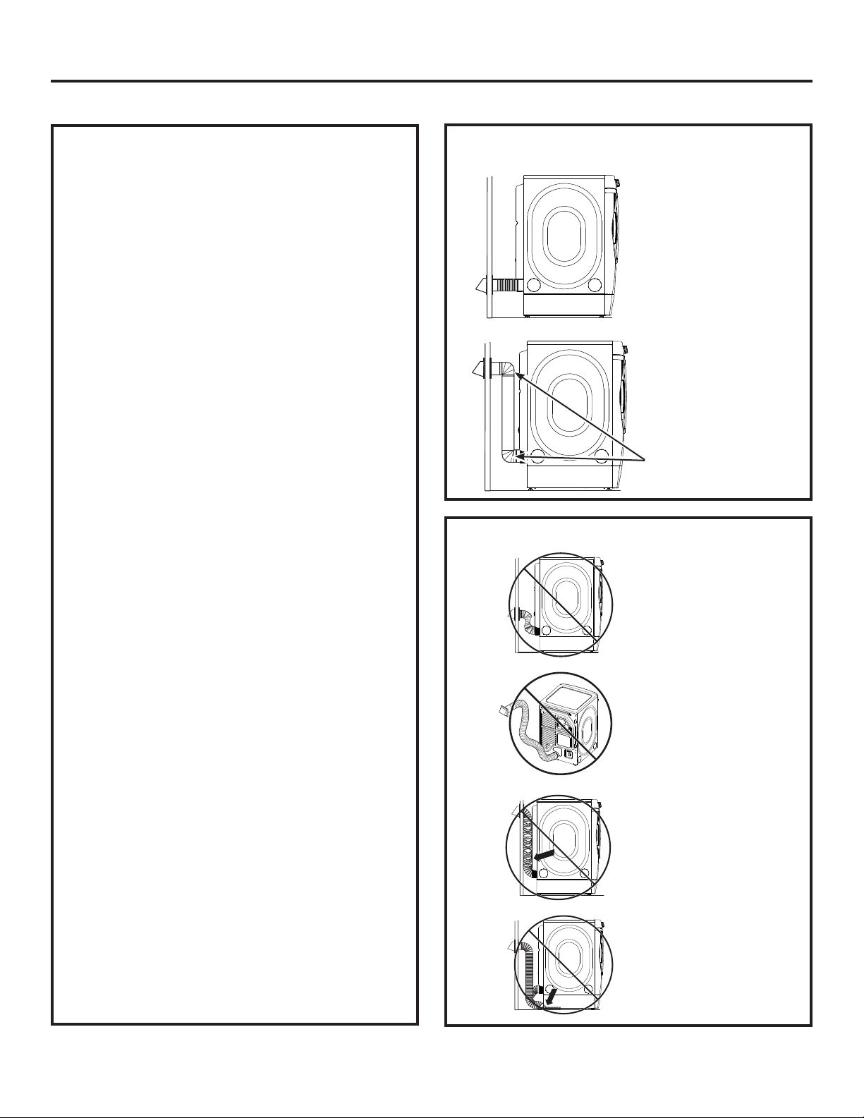
FOR TRANSITION VENTING (DRYER TO
WALL), DO
:
• DO cut duct as
short as possible
and install
straight into wall.
DO use elbows
•
when turns are
necessary.
Elbows
DO NOT:
• DO NOT bend or
collapse ducting.
Use elbows
if turns are
necessary.
•
DO NOT use
excessive
exhaust length.
Cut duct as short
as possible.
• DO NOT crush
duct against the
wall.
DO NOT set
•
dryer on duct.
24
Page 25
EXHAUST LENGTH
Installation Instructions
Using exhaust longer than specified length will:
• Increase the drying times and the energy cost.
• Reduce the dryer life.
• Accumulate lint, creating a potential fire
hazard.
The correct exhaust installation is YOUR
RESPONSIBILITY.
Problems due to incorrect installation are not
covered by the warranty.
The MAXIMUM ALLOWABLE length of the exhaust
system depends upon the type of duct, number
of turns, the type of exhaust hood (wall cap) and
all conditions noted on the chart.
• Internal elbows added for side or bottom vent
conversions must be included in the total elbow
count.
• Any elbow greater than 45° should be treated as a
90° elbow.
• Two 45° elbows will be treated like one 90° elbow.
• For the side exhaust installations, add one 90°
elbow to the chart.
• The total vent system length includes all the
straight portions and elbows of the system
(transition duct included).
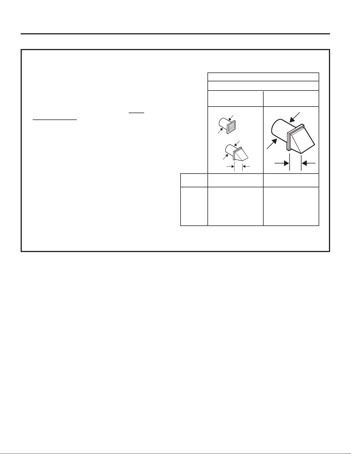
EXHAUST LENGTH
RECOMMENDED MAXIMUM LENGTH
Exhaust Hood Types
Recommended Use only for short- run
installations
4” DIA
4” DIA
1
”
4
No. of 90º Rigid Rigid
Elbows Metal Metal
0 90 Feet 60 Feet
1 60 Feet 45 Feet
2 45 Feet 35 Feet
3 35 Feet 25 Feet
4 25 Feet 15 Feet
2
4
”
DIA
ø2”
25
Page 26
Installation Instructions
EXHAUSTING THE DRYER (cont.)
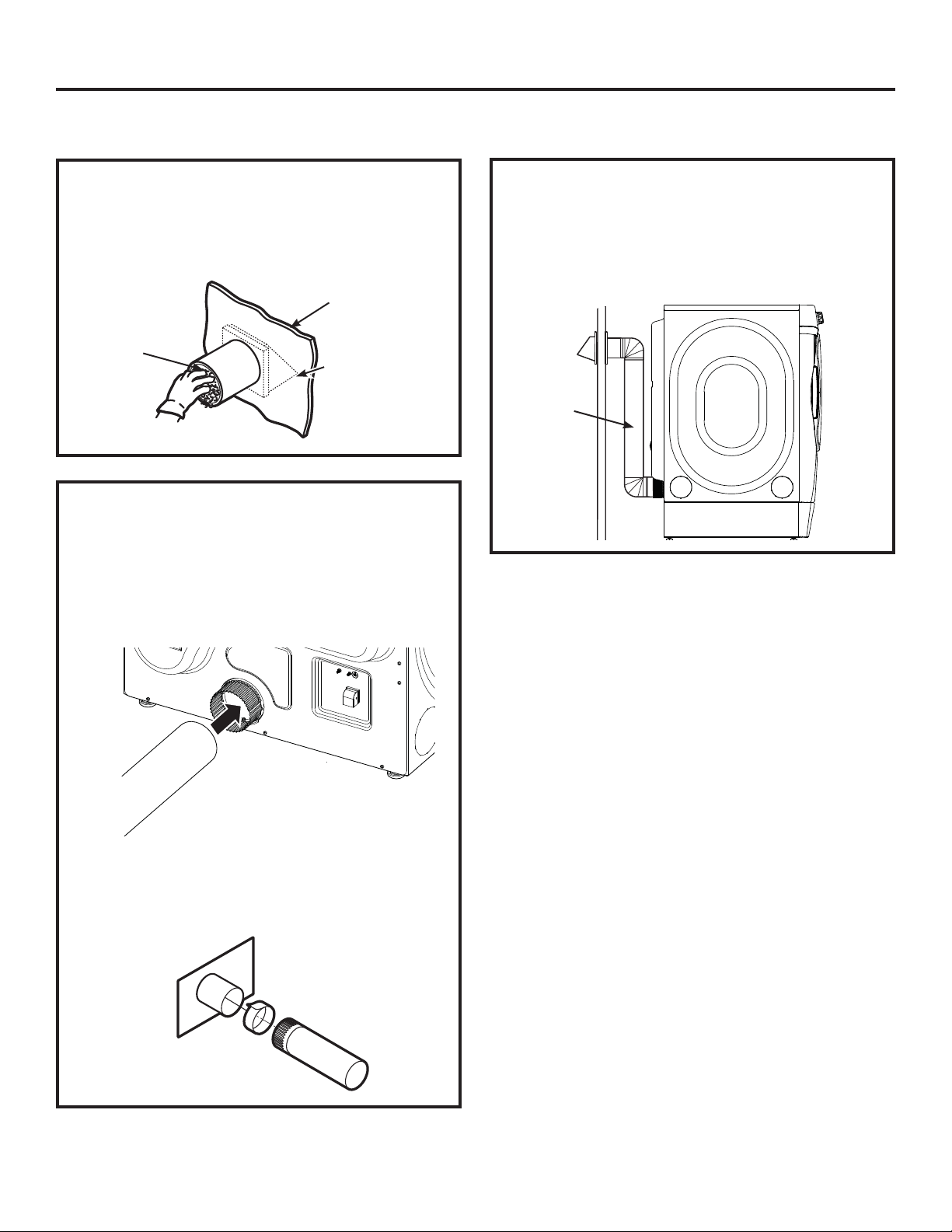
BEFORE YOU BEGIN
• Remove and discard existing plastic or metal foil
duct and replace with UL-listed duct.
Remove any lint from the wall exhaust opening.
•
Wall
Internal
Duct
Opening
Check that exhaust
hood damper opens
and closes freely.
STANDARD REAR EXHAUST
RECOMMENDED CONFIGURATION TO
MINIMIZE EXHAUST BLOCKAGE
Using duct elbows will prevent duct kinking and
collapsing.
Transition
Ducting
We recommend that you install your dryer before
installing your washer. This will permit direct
access for easier exhaust connection.
Slide the end of the exhaust duct on the back of the
dryer and secure with duct tape or a hose clamp.
Duct
NOTE: We strongly recommend using rigid metal
exhaust duct.
•
For straight-line installation, connect the dryer
exhaust to the wall, using duct tape.
Wall Side
Dryer
Side
26
Page 27
Installation Instructions
SIDE VENTING:
Dryer Exhaust to right of cabinet for Electric
models only.
Dryer Exhaust to left of cabinet for Gas and
Electric models.
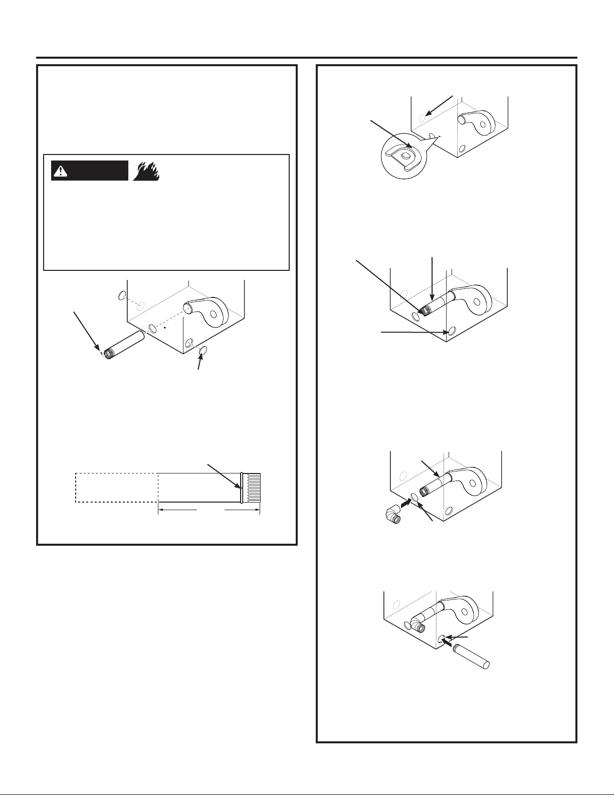
WARNING
Close the back opening with cover plate (Kit
WE1M454).
Disconnect dryer from electrical supply.
Wear gloves and arm guards.
Failure to do so may result in fire, electrical shock
or lacerations.
Remove
screw
and save
Detach and remove the right or left side knockout
as desired. Remove the screw inside the dryer
exhaust duct and save. Pull the duct out of the
dryer.
Right
- Fire Hazard
Left
Remove desired
knockout (one only)
Fixing hole
TAB LOCATION
Not for gas
Bend tab
up 45°
Through the rear opening, locate the tab in the
middle of the appliance base. Lift the tab to about
using a flat-blade screwdriver.
45°,
ADDING A NEW DUCT
Fixing hole
Left side
exhaust
Reconnect the cut portion (A) of the duct to the
blower housing. Make sure that the shortened
duct is aligned with the tab in the base. Use the
screw saved previously to secure the duct in place
through the tab on the appliance base.
Portion “A”
ADDING ELBOW AND DUCT FOR EXHAUST TO
LEFT OR RIGHT SIDE OF CABINET
Internal duct
A
15 3ø4”
Cut the duct as shown and keep portion A.
Rear opening
• Insert the 4” elbow through the rear opening and
connect the elbow to the dryer internal duct.
Insert the 4” duct through the side opening and
•
connect it to the elbow.
Side opening
Do not pull or damage the electrical wires and
do not remove the vinyl cover from the electrical
components inside the dryer when inserting the
duct. A slight interference may occur between the
exhaust and the wire components.
27
Page 28
Installation Instructions
EXHAUSTING THE DRYER (cont.)
SIDE VENTING (cont.)
ADDING ELBOW AND DUCT FOR EXHAUST TO
LEFT OR RIGHT SIDE OF CABINET (cont.)
• Apply duct tape as
shown on the joint
between the dryer
internal duct and the
elbow, and also the joint
between the elbow and
the side duct.
Use 4” rigid metal ducting
only inside the dryer. Internal duct joints must be
secured with tape, otherwise they may separate
and cause a safety hazard.
ADDING COVER PLATE TO REAR OF CABINET
(SIDE EXHAUST)
Duct tape
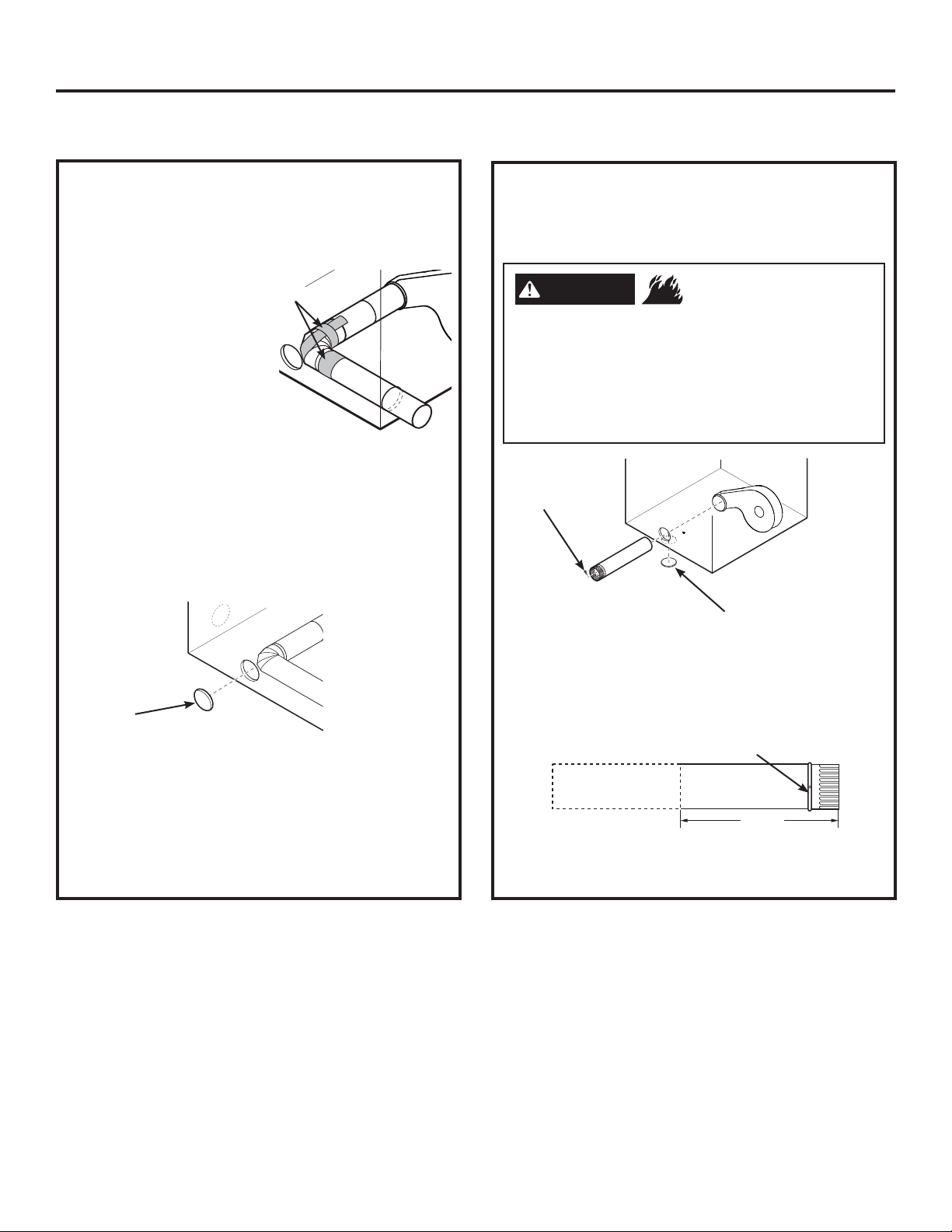
BOTTOM VENTING:
Dryer Exhaust to the bottom of cabinet for
Gas and Electric models.
WARNING
Close the back opening with cover plate (Kit
WE1M454).
Disconnect dryer from electrical supply.
Wear gloves and arm guards.
Failure to do so may result in fire, electrical shock
or lacerations.
Remove
screw
and save
Bottom
- Fire Hazard
Remove desired
knockout (one only)
Plate
(Kit WE1M454)
Connect standard metal elbows and ducts to
complete the exhaust system. Cover back opening
with a plate (Kit WE1M454) available from your
local service provider. Place dryer in final location.
NEVER LEAVE THE BACK OPENING WITHOUT THE
PLATE.
(Kit WE1M454.)
Remove the screw inside the dryer exhaust duct
and save. Pull the duct out of the dryer. Detach
and remove the bottom knockout.
Fixing hole
A
15 3ø4”
Cut the duct as shown and keep portion A.
28
Page 29
Installation Instructions
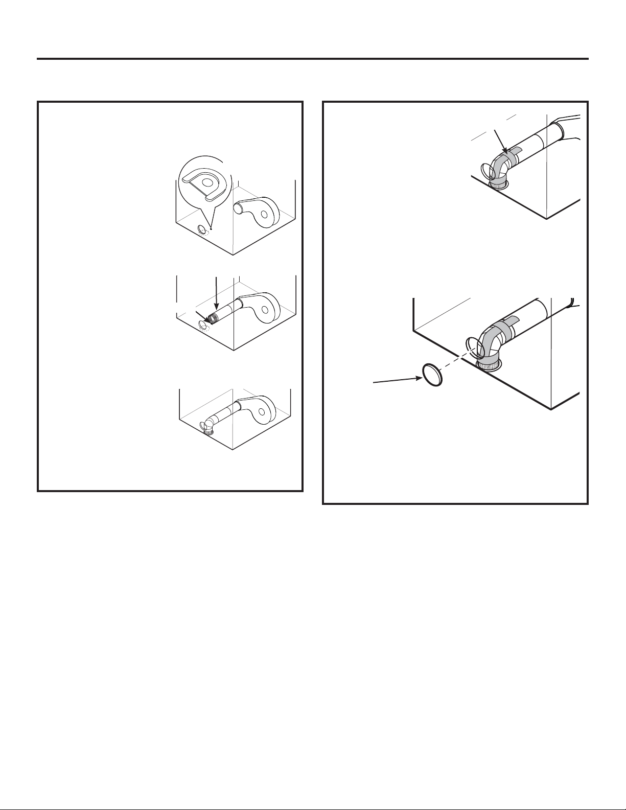
BOTTOM VENTING (cont.)
ADDING A NEW DUCT
• Through the rear
opening, locate
the tab in the
middle of the
appliance base.
Lift the tab to
about 45° using
a flat-blade
screwdriver.
•
Reconnect the cut
portion (A) of the
Portion “A”
duct to the blower
housing. Make
Fixing hole
sure that the
shortened duct is
aligned with the
tab in the base.
Use the screw saved previously to secure the duct
in place through the tab on the appliance base.
•
Insert the 4” elbow
through the bottom
opening and connect to
the dryer internal duct.
Be sure not to pull or damage the electrical wires
inside the dryer when inserting the duct.
Bend tab
up 45°
•
Apply duct tape as
shown on the joint
Duct tape
between the dryer
internal duct and the
elbow, and also the
joint between the
elbow and the bottom
duct.
Internal duct joints must be secured with tape;
otherwise, they may separate and cause a safety
hazard.
ADDING COVER PLATE TO REAR OF CABINET
(BOTTOM EXHAUST)
Plate
(Kit WE1M454)
Connect standard metal elbows and ducts to
complete the exhaust system. Cover back opening
with a plate (Kit WE1M454) available from your
local service provider. Place dryer in final location.
NEVER LEAVE THE BACK OPENING WITHOUT THE
PLATE.
(Kit WE1M454.)
29
Page 30
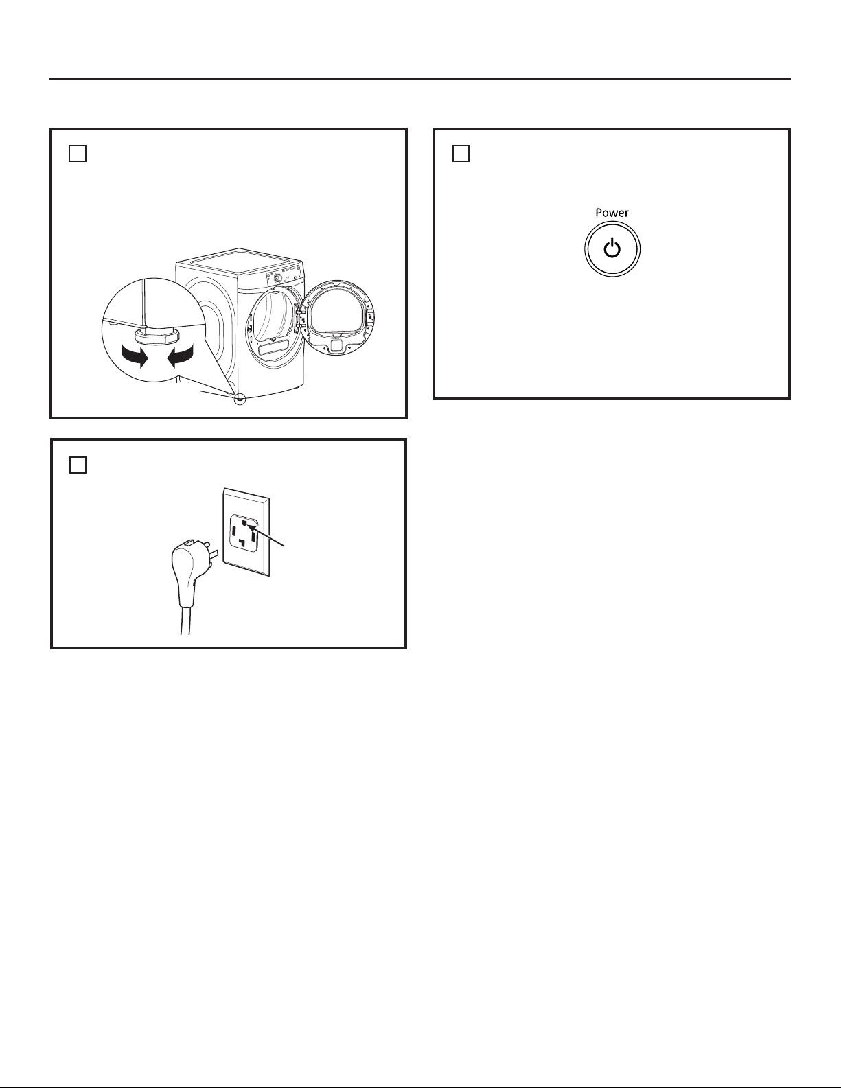
FINAL SETUP
Installation Instructions
1
LEVEL THE DRYER
Stand the dryer upright near the final location and
adjust the four leveling legs at the corners to ensure
that the dryer is level from side to side and front to
rear.
Raise
2
PLUG DRYER IN
Lower
Ensure proper
ground exists
before use.
3
DRYER START-UP
Press the Power button.
NOTE: If the dryer has been exposed to
temperatures below freezing for an extended
period of time, allow it to warm up before pressing
Power. Otherwise, the display will not come on.
The dryer is now ready for use.
30
Page 31

Installation Instructions
REVERSING THE DOOR SWING (if desired)
IMPORTANT NOTES
• Read the instructions all the way through before
starting.
• Handle parts carefully to avoid scratching paint.
• Set screws down by their related parts to avoid
using them in the wrong places.
• Provide a non-scratching work surface for
the doors.
IMPORTANT: Once you begin, do not move the
cabinet until door-swing reversal is completed.
These instructions are for changing the hinges
IURPWKHULJKWVLGHWRWKHOHIWVLGH³LI\RXHYHUZDQW
to switch them back to the right side, follow these
same instructions and reverse all references
to the left and right.
• Normal completion time to reverse the door swing
is 30–60 minutes.
TOOLS YOU WILL NEED
#2 Phillips-head screwdriver T-25 torx driver 1/4” nut driver
DOOR PARTS
2 - #8 x 1/2” Screws
(striker plate)
10 - #8 x 7/8” Screws
(door assembly)
2 - Panel Plugs 1 - Door Mask 1 - Chrome Door Cover
6 - #8 x 1/2” Screws
(hinge assembly and
handle spacer)
2 - #8 x 1/2” Screws
Assembly
BEFORE YOU START
Unplug the dryer from its electrical outlet.
(door mask)
2 - #10 x 5/8” Screws
(hinge)
1 - Handle Spacer 1 - Inner Door
2 - #10 x 5/8” Screws
(panel plug)
Assembly
1 - #8 x 3/8” Screws
(hinge pin)
31
Page 32

Installation Instructions
REVERSING THE DOOR SWING (if desired)
1
REMOVE THE DOOR ASSEMBLY
A. Open the door to fully.
B. Remove 2 screws (#10 x 5/8”) from the hinge,
starting with the bottom screw. The door will tilt
away from the front panel, but will come to rest
in place.
C. Lift the door slightly and unhook if from the front
panel.
D. Place the door on a soft and flat surface.
3
DISASSEMBLE THE DOOR ASSEMBLY
A. Place door on a soft and flat surface with the
inner door frame facing upward.
B. Remove 10 screws (#8 x 7/8”) from the perimeter
of the door frame.
C. Separate the inner door frame from the chrome
door cover. Set the inner door frame aside on a
soft and flat surface.
RE-LOCATE THE HINGE STRIKER AND
2
FRONT PANEL PLUGS
IMPORTANT: Note the location of the hinge (left or
right) before removing.
A. Remove 2 screws (#10 x 5/8”) and front panel
plugs from the front panel.
B. Re-install front panel plugs and screws on
opposite side of the door opening.
C. Remove 2 screws (#8 x 1/2”) and hinge striker
from the front panel.
D. Rotate hinge striker 180 degrees and re-install
with screws on the opposite side of the door
opening.
RE-LOCATE THE DOOR MASK
4
A. Place the chrome door cover on a soft and flat
surface so that the door mask is facing upwards.
B. Remove 2 screws (#8 x 1/2”) that secure the door
mask in place.
C. Rotate the door mask 180 degrees and re-install
screws to secure door mask.
BEFORE
AFTER
D. Re-location is complete. Set chrome door cover
aside.
32
Page 33

Installation Instructions
RE-LOCATE HINGE ASSEMBLY AND
5
HANDLE SPACER
A. Place the inner door frame on a soft and flat
surface so that the inner door gasket is facing
updwards.
B. Remove 6 screws (#8 x 1/2”) that secure the
hinge assembly and handle spacer.
RE-LOCATE HINGE ASSEMBLY AND
5
HANDLE SPACER (CONT.)
D. Rotate hinge assembly 180 degrees and
re-locate on the opposite side of the inner door
frame.
E. Rotate the handle spacer 180 degrees and
re-locate on the opposite side of the inner door
frame.
Handle
spacer
Hinge
assembly
C. Separate the hinge assembly and handle spacer
from the inner door frame.
Hinge
assembly
Handle
spacer
F. Re-install screws securing hinge assembly and
handle spacer.
33
Page 34

Installation Instructions
REVERSING THE DOOR SWING (if desired)
RE-ASSEMBLE DOOR ASSEMBLY
6
A. Place the chrome door cover on a soft flat
surface with the plastic outer protect cover
facing down.
B. Lower the inner door frame onto the chrome
door cover.
C. Ensure that all screw holes are aligned and
re-install 10 screws (#8 x 7/8”).
8
RE-INSTALL DOOR ASSEMBLY
A. Install the door assembly by guiding the hinge
pin screw head through the key hole on the
front panel and lowering the door assembly into
place.
B. Open the door approximately 140 degrees to
provide access to the screw hole locations.
C. Starting with the top screw, re-install the 2
screws (#10 x 5/8”) which secure the door to the
front panel.
RE-LOCATE HINGE PIN SCREW
7
A. Remove the hinge pin screw from the hole
labeled “D”.
B. Re-install the hinge pin screw into the hole
labeled “W”.
34
Page 35

Notes
35
Page 36

Installation Instructions
STACKING THE WASHER AND DRYER (if desired)
BEFORE YOU BEGIN
Read these instructions completely and carefully.
IMPORTANT – Save these instructions for
•
local electrical inspector’s use.
IMPORTANT – Observe all governing
•
codes and ordinances.
•
Note to Installer – Be sure to leave these
instructions with the Consumer.
•
Note to Consumer – Keep these instructions for
future reference.
•
Service must be performed by a qualified
installer.
•
Proper installation is the responsibility of the
installer.
• Disconnect power before installing. Failure to do
so could result in serious injury or death.
WARNING
Use two or more people to install dryer.
Failure to do so may result in back or other injury.
• Avoid Tipping and Rupture of Utility Services.
Dryer must be securely attached to the washer.
DO NOT place the washer on top of the dryer.
Failure to do so could result in personal injury/
death or property damage.
• Mobile Home or Manufactured Home Installation
– Stacking of a gas dryer is not permitted in a
mobile home or manufactured home.
- Excessive Weight Hazard
MINIMUM CLEARANCE OTHER THAN
ALCOVE OR CLOSET INSTALLATION
Minimum clearance to combustible surfaces and
for air opening are: 0” both sides, 3” front/rear and
1” top. Consideration must be given to provide
adequate clearance for installation and service.
REQUIREMENTS FOR ALCOVE OR
CLOSET INSTALLATION
• Your dryer is approved for installation in an
alcove or closet, as stated on a label on the dryer
back.
The dryer MUST be vented to the outdoors. See
•
the EXHAUSTING THE DRYER section.
Minimum clearance between dryer cabinet and
•
adjacent walls or other surfaces is:
0” either side
3” front and rear
1” top
Minimum vertical space from floor to overhead
•
shelves, cabinets, ceilings, etc., is 52”.
Closet doors must be louvered or otherwise
•
ventilated and have at least 60 square inches
of open area equally distributed. If the closet
contains both a washer and a dryer, doors must
contain a minimum of 120 square inches of open
area equally distributed.
The closet should be vented to the outdoors to
•
prevent gas pocketing in case of gas in the supply
line.
No other fuel-burning appliance shall be installed
•
in the same closet with the dryer (gas models
only).
NOTE: WHEN THE EXHAUST DUCT IS LOCATED AT
THE REAR OF THE DRYER, MINIMUM CLEARANCE
FROM THE WALL IS 5.5 INCHES.
GE STACK KIT:
Order on-line at GEApplianceParts.com, 24 hours a day or by
phone at 800.626.2002 during normal business hours.
Part Number Accessory
GEFLSTACK Complete Stack Kit
36
Page 37

Installation Instructions
STACKING THE WASHER AND
DRYER (if desired) (cont.)
STACKING KIT GEFLSTACK CONTENTS
(OPTIONAL ACCESSORY)
NOTE: Models GFDR480, GFDR485, GFWR4800
and GFWR4805 cannot be stacked.
Left hand bracket
Right hand bracket
4 rubber pads
4 #12 x 1” screws
4 #8 x 1/2” screws
INSTALLING THE STACK BRACKET
KIT
1
REMOVE THE DRYER LEVELING LEGS
A. Carefully lay the dryer on its side. Use the
packing material so you don’t scratch the finish
on the dryer.
B. Use an open-end wrench or pliers to remove the
dryer leveling legs.
TOOLS YOU WILL NEED
Phillips screwdriver
Gloves
Open-ended wrench
Level
Pliers
INSTALLATION PREPARATION
Remove the packaging.
Flatten the product carton to use as a pad to lay the
dryer down on its side. Continue using the carton to
protect the finished floor in front of
the installation location.
Back out and
remove all 4
leveling legs
2
INSTALL RUBBER PADS TO DRYER
BASE
Locate the 4 rubber pads in the parts package.
Remove the adhesive backing and firmly place
over each bracket where you removed the
leveling legs.
Place pads over
all four leveling
leg brackets
37
Page 38

Installation Instructions
3
INSTALL BRACKET TO DRYER
A. Align the holes in the left bracket with the holes
in the bottom left corner of the dryer. Use a
Phillips screwdriver to install the 2 #12 x 1”
tapping screws.
B. Repeat the above step with the right bracket on
the bottom right corner of the dryer.
Install
Bottom of dryer
C. Set the dryer upright.
NOTE: Make sure to set the dryer on a piece of
packing material so the brackets that are attached
to the bottom of the dryer do not damage the floor.
brackets
on
bottom
back
4
INSTALL DRYER AND BRACKET ON
WASHER (CONT.)
B. Align the holes in the bracket with the holes
in the back of the washer. Using a Phillips
screwdriver, attach the 2 #8 x 1/2” tapping
screws. Repeat on both sides of the washer
Attach brackets to
back of washer
5
FINALIZE THE INSTALLATION
A. Refer to the washer Installation Instructions to
complete the washer installation.
.
4
INSTALL DRYER AND BRACKET ON
WASHER
A. Lift the dryer on top of the washer. Be careful
not to scratch the top of the washer with the
brackets. Protect the washer control panel with
cardboard or other protection. Be sure to lift the
dryer high enough to clear the washer control
panel.
More than two people are recommended to lift
the dryer into position because of its weight and
size. Failure to do so could result in personal
injury or death.
B. Refer to the dryer Installation Instructions to
complete the dryer installation.
C. Carefully slide or walk the stacked washer and
dryer into place. Use felt pads or other sliding
device to assist moving and to protect flooring.
Do not push on the dryer once installed to top of
the washer. Pushing on the dryer may result in
pinched fingers.
Place
hands
here
Place
hands
here
38
Page 39

Before you call for service…
Troubleshooting Tips
Save time and money! Review the charts on the following pages,
or visit GEAppliances.com. You may not need to call for service.
PROBLEM Possible Causes What To Do
Dryer shakes or Some shaking/noise is normal. • Move dryer to an even floor space, or adjust leveling legs
makes noise Dryer may be sitting unevenly as necessary until even.
Clothes take too long Improper or obstructed ducting • Check the Installation Instructions to make sure the
to dry dryer venting is correct.
• Make sure ducting is clean, free of kinks and
unobstructed.
• Check to see if outside wall damper operates easily.
Improper sorting • Separate heavy items from lightweight items (generally,
a well-sorted washer load is a well-sorted dryer load).
Large loads of heavy fabrics • Large, heavy fabrics contain more moisture and take
(like beach towels) longer to dry. Separate large, heavy fabrics into smaller
loads to speed drying time.
Controls improperly set • Match control settings to the load you are drying.
Lint filter is full • Clean lint filter before every load.
Blown fuses or tripped circuit • Replace fuses or reset circuit breakers. Since most
breaker dryers use 2 fuses/breakers, make sure both are
operating.
Overloading/combining loads • Do not put more than one washer load in the dryer at
a time.
Underloading • If you are drying only one or two items, add a few items
to ensure proper tumbling.
The Dry dryness level Load consists of a mixture • When combining heavy and light fabrics in a load,
was chosen but load is of heavy and light fabrics choose More Dry.
still damp
Exhaust system is blocked • Inspect and clean exhaust system.
Control buttons not Controls accidentally put in • Press Start/Pause.
responding service mode
Controls accidentally put in • Hold the Lock Control button for 3 seconds to unlock the dryer.
lock mode
Controls performed an • Reset the in-house breaker.
incorrect operation
Dryer doesn’t start Control panel is “asleep” • This is normal. Press Power to activate the control panel.
Dryer is unplugged • Make sure the dryer plug is pushed completely into
the outlet.
Fuse is blown/circuit breaker • Check the building’s fuse/circuit breaker box and
is tripped replace fuse or reset breaker. NOTE: Electric dryers
use two fuses or breakers.
Dryer was accidentally paused • If the light on the Start/Pause button is flashing,
when starting Delay Dry the dryer is paused. Press Start/Pause to restart
the countdown.
No numbers displayed Dryer is continuously • This is normal. When the dryer senses a low level of
during cycle, only lights monitoring the amount of moisture in the load, the dryer will display the dry time
moisture in the clothes remaining.
39
Page 40

Before you call for service…
PROBLEM Possible Causes What To Do
Time Remaining The estimated time may change • This is normal.
jumped to a when a smaller load than usual
lower number is drying
Cannot make a The dryness Level, Temp • This is normal.
selection and the or option that you are
dryer beeps twice trying to select is incompatible
with the chosen dry cycle
Dryer is running but The Ext Tumble • This is normal. During extended tumbling, the time
00 is displayed in option was chosen remaining is not displayed. The extended tumbling
Time Remaining option lasts approximately 60 minutes.
Clean Lint Filter (message) Power button was activated • Press Start/Pause to begin a dry cycle and the message
will disappear.
Dryer doesn’t heat Fuse is blown/circuit breaker • Check the building’s fuse/circuit breaker box and
is tripped; the dryer may tumble replace both fuses or reset both breakers. Your dryer
but not heat may tumble if only one fuse is blown or one breaker
tripped.
Gas service is off (gas models • Make sure gas shutoff at dryer and main shutoff are
only) fully open.
LP gas supply tank is empty • Refill or replace tank. Dryer should heat when utility
or there has been a utility service is restored.
interruption of natural gas
(gas models only)
Inconsistent drying times Type of heat • Drying time will vary according to the type of heat used.
If you recently changed from an electric to a gas
(natural or LP) dryer, or vice versa, the drying time
could be different.
Type of load and • The load size, types of fabric, wetness of clothes and the
drying conditions length and condition of the exhaust system will affect
drying times.
Clothes are still wet The door was opened mid-cycle. • A dry cycle must be reselected each time a new load
and dryer shut off The load was then removed from is put in.
after a short time the dryer and a new load put in
without selecting a new cycle
Small load • When drying 3 items or less, choose Speed Dry or
Time Dry.
Load was already dry except • Choose Speed Dry or Time Dry to dry damp collars
for collars and waistbands and waistbands. In the future, when drying a load with
collars and waistbands, choose More Dry.
Dryer is not level • Move dryer to an even floor space or adjust leveling legs
as necessary until even.
Clothes are wrinkled Overdrying • Select a shorter drying time.
• Remove items while they still hold a slight amount of
moisture. Select a Less Dry or Damp setting.
Letting items sit in dryer after • Remove items when cycle ends and fold or hang
cycle ends immediately, or use the Ext Tumble option.
Overloading • Separate large loads into smaller ones.
40
Page 41

Before you call for service… GEAppliances.com
PROBLEM Possible Causes What To Do
Clothes shrink Some fabrics will naturally shrink • To avoid shrinkage, follow garment care labels exactly.
when washed. Others can be
safely washed, but will shrink
in the dryer.
item, do not machine wash or tumble dry it.
Greasy spots on clothes Improper use of fabric softener • Follow directions on fabric softener package.
Drying dirty items • Use your dryer to dry only clean items. Dirty items can
with clean ones stain clean items and the dryer.
Clothes were not • Sometimes stains which cannot be seen when the
completely clean clothes are wet appear after drying. Use proper washing
procedures before drying.
Lint on clothes Lint filter is full • Clean lint screen before each load.
Improper sorting • Sort lint producers (like chenille) from lint collectors
(like corduroy).
Static electricity can attract lint • See suggestions in this section under Static occurs.
Overloading • Separate large loads into smaller ones.
Paper, tissue, etc., left in pockets • Empty all pockets before laundering clothes.
• Some items may be pressed back into shape after drying.
• If you are concerned about shrinkage in a particular
Static occurs No fabric softener was used • Try a fabric softener.
• Bounce® Fabric Conditioner Dryer Sheets have been
approved for use in all GE Dryers when used in
accordance with the manufacturer’s instructions.
Overdrying • Try a fabric softener.
• Adjust setting to Less Dry or Damp.
Synthetics, permanent press • Try a fabric softener.
and blends can cause static
Collars and waistbands The dryness monitor senses • Choose Speed Dry or Time Dry to dry damp collars
still wet at end of cycle that the body of the clothes and waistbands. In the future, when drying a load with
is dry collars and waistbands, choose More Dry.
Slight variation This is normal • Due to the metallic properties of paint used for this unique
in metallic color product, slight variations of color may occur due to
viewing angles and lighting conditions.
Door is too foggy to see Steam condenses on inner door • This is normal.
clothes during a steam
cycle
Water seen on inside of Steam condenses on these • This is normal.
door and top of lint filter surfaces
when opening door after
steam cycle
Small areas on clothes are Steam condenses on inner drum • If using the Steam Dewrinkle cycle, manually reduce the
damp after steam cycle cycle time. If using the Steam Refresh cycle, add more
garments to the load.
41
Page 42

Before you call for service…
PROBLEM Possible Causes What To Do
Small amount of water Inadequate load size for steam • If using the Steam Dewrinkle cycle, manually reduce the
on floor in front of dryer cycle selected, excess steam cycle time. If using the Steam Refresh cycle, add more
condenses inside cabinet and garments to the load.
leaks out
Water on floor in back Loose water hose connection to • Tighten connection.
of dryer valve
Hose missing rubber washer at • Install rubber washer provided with hose.
connection with valve
Dryer makes water Water valve is open filling steam • This is normal.
noises generator
Steam generator is dispensing • This is normal.
steam into drum
Water drips from door Steam condenses on inner door • This is normal.
when opened after
a Steam Cycle
Cannot see steam at Steam released at different • This is normal.
beginning of cycle times in the cycle
Cannot see steam at any The steam nozzle might be • Call 800.GE.CARES to order nozzle replacement kit
time during cycle clogged with debris from your WE25M71 or to request a technician to replace this for you.
water supply
Garments still wrinkled Too many garments • Load fewer garments; manually increase time.
after steam cycle
Dryer continues to Ext Tumble was selected • Ensure Ext Tumble option is not selected. For the
tumble after display Steam Refresh cycle, Ext Tumble will automatically
says Complete be turned on and cannot be turned off.
42
Page 43

GE Dryer Warranty. (For customers in the United States) GEAppliances.com
All warranty service provided by our Factory Service Centers,
®
or an authorized Customer Care
technician. To schedule
service, on-line, visit us at GEAppliances.com, or call 800.
GE.CARES (800.432.2737).
Staple your receipt here.
Proof of the original purchase
date is needed to obtain
service under the warranty.
Please have serial number and model number available when
calling for service.
Servicing your appliance may require the use of the onboard data port for diagnostics. This gives a GE
Factory Service technician the ability to quickly diagnose any issues with your appliance and helps GE
improve its products by providing GE with information on your appliance. If you do not want your appliance
data to be sent to GE, please advise your technician NOT to submit the data to GE at the time of service.
For The Period Of: We Will Replace:
One Year Any part of the dryer which fails due to a defect in materials or workmanship. During this
From the date of the limited one-year warranty, GE will also provide, free of charge, all labor and related service costs
original purchase to replace the defective part.
What Is Not Covered (in the United States):
Service trips to your home to teach you how to use the
product.
Improper installation, delivery or maintenance.
Failure of the product if it is abused, misused or used for
other than the intended purpose or used commercially.
Replacement of the light bulb after its expected useful
life.
Replacement of house fuses or resetting of circuit
breakers.
Damage to the product caused by accident, fire, floods
or acts of God.
Incidental or consequential damage caused by possible
defects with this appliance.
Damage caused after delivery.
Product not accessible to provide required service.
Defects or damage due to operation in freezing
temperatures.
Products which are not defective or broken, or which
are working as described in the Owner’s Manual.
(;&/86,212),03/,(':$55$17,(6³<RXUVROHDQGH[FOXVLYHUHPHG\LVSURGXFWUHSDLUDVSURYLGHGLQ
this Limited Warranty. Any implied warranties, including the implied warranties of merchantability or
fitness for a particular purpose, are limited to one year or the shortest period allowed by law.
This warranty is extended to the original purchaser and any succeeding owner for products purchased for home
use within the USA. If the product is located in an area where service by a GE Authorized Servicer is not available,
you may be responsible for a trip charge or you may be required to bring the product to an Authorized GE Service
location for service. In Alaska, the warranty excludes the cost of shipping or service calls to your home.
Some states do not allow the exclusion or limitation of incidental or consequential damages. This warranty gives
you specific legal rights, and you may also have other rights which vary from state to state. To know what your
legal rights are, consult your local or state consumer affairs office or your state’s Attorney General.
Warrantor: General Electric Company. Louisville, KY 40225
43
Page 44

GE Dryer Warranty. (For customers in Canada)
All warranty service provided by our Factory Service Centres or an authorized technician. For service,
call 1.800.561.3344.
Please have serial number and model number available when calling for service.
Servicing your appliance may require the use of the onboard data port for diagnostics. This gives a GE
Factory Service technician the ability to quickly diagnose any issues with your appliance and helps GE
improve its products by providing GE with information on your appliance. If you do not want your appliance
data to be sent to GE, please advise your technician NOT to submit the data to GE at the time of service.
For The Period Of: We Will Replace:
One Year Any part of the dryer which fails due to a defect in materials or workmanship. During this
From the date of the limited one-year warranty, GE will also provide, free of charge, all labor and related service costs
original purchase to replace the defective part.
What Is Not Covered (in Canada):
Service trips to your home to teach you how to use the
product.
Improper installation, delivery or maintenance.
Failure of the product if it is abused, misused or used for
other than the intended purpose or used commercially.
Replacement of the light bulb after its expected useful
life.
Replacement of house fuses or resetting of circuit
breakers.
(;&/86,212),03/,(':$55$17,(6³<RXUVROHDQGH[FOXVLYHUHPHG\LVSURGXFWUHSDLUDVSURYLGHGLQWKLV/LPLWHG
Warranty. Any implied warranties, including the implied warranties of merchantability or fitness for a particular purpose,
are limited to one year or the shortest period allowed by law.
Damage to the product caused by accident, fire, floods
or acts of God.
Incidental or consequential damage caused by possible
defects with this appliance.
Damage caused after delivery.
Product not accessible to provide required service.
Defects or damage due to operation in freezing
temperatures.
Products which are not defective or broken, or which
are working as described in the Owner’s Manual.
This warranty is extended to the original purchaser and any succeeding owner for products purchased in Canada
for home use within Canada. In-home warranty service will be provided in areas where it is available and deemed
reasonable by Mabe to provide.
44
WARRANTOR IS NOT RESPONSIBLE FOR CONSEQUENTIAL DAMAGES
Warrantor: MC Commercial, Burlington, ON
Page 45

Mesures de sécurité ....... 46–48
Foncionnement
Panneau de contrôle ............48–52
Guide de démarrage ................49
Utilisation de la sécheuse ..........53
Caractéristiques. . . . . . . . . . . . . . . . . . . . .54
Entretien et nettoyage ........ 55
Installation
Avant de commencer ...........56-58
Branchement des boyaux
d‘arrivée ............................59
Raccordement
d’une sécheuse à gaz ...........60–63
Raccordement
d’une sécheuse électrique ......64–66
Évacuation de la sécheuse .....67–73
Installation finale ....................74
Inversion de l’ouverture
de la porte ......................75–78
Superposer la sécheuse
à la laveuse ....................80–82
Conseils de dépannage ....83–86
Soutien au consommateur
Garantie ........................... 88
Soutien au consommateur ........ 89
Inscrivez ici les numéros
de modèle et de série :
Modèle N° ________________
Série N° __________________
Ces informations figurent
sur l’étiquette située à l’avant
de la sécheuse, derrière la porte.
45
Page 46

CONSIGNES DE SÉCURITÉ IMPORTANTES.
LISEZ TOUTES LES INSTRUCTIONS AVANT D’UTILISER VOTRE APPAREIL.
Ceci est un symbole d’alerte de sécurité. Ce symbole prévient d’un risque mortel ou de blessures encouru par
vous et d’autres personnes. Tous les messages de sécurité s’inscriront à la suite du symbole d’alerte et du mot
« DANGER », « AVERTISSEMENT » ou « MISE EN GARDE ». Ces mots sont associés aux définitions suivantes :
DANGER
AVERTISSEMENT
MISE EN GARDE
Indique une situation dangereuse qui, si elle n’est pas évitée, causera des blessures sévères, voire la mort.
Indique une situation dangereuse qui, si elle n’est pas évitée, peut causer des blessures sévères,
voire la mort.
Indique une situation dangereuse qui, si elle n’est pas évitée, peut causer des blessures mineures
ou modérément graves.
INSTRUCTIONS DE SÉCURITÉ IMPORTANTES
AVERTISSEMENT
Lisez toutes les instructions avant d’utiliser l’appareil.
NE séchez PAS les articles qui ont été précédemment nettoyés, lavés, trempés ou détachés à l’aide d’essence, de
solvants de nettoyage à sec ou d’autres substances inflammables ou explosives, puisqu’ils peuvent émettre des
vapeurs susceptibles de s’enflammer ou d’exploser.
N’autorisez PAS les enfants à jouer sur ou dans cet appareil. Une surveillance étroite est requise lorsque des enfants
se trouvent à proximité de l’appareil en fonctionnement. Enlevez la porte de la sécheuse lorsque l’appareil est mis hors
service ou au rebut.
NE vous penchez PAS dans l’appareil lorsque le tambour est en rotation.
N’installez PAS et ne rangez PAS cet appareil à un endroit exposé aux intempéries.
NE modifiez PAS les commandes.
à moins que cela ne soit expressément recommandé dans les instructions d’entretien ou de réparation destinées à
l’utilisateur dont vous avez une compréhension et une compétence suffisantes pour les appliquer.
N’employez PAS de produits assouplissants NI d’agents antistatiques à moins que leur utilisation ne soit recommandée
par leurs fabricants.
N’utilisez PAS de chaleur pour sécher des articles qui contiennent du caoutchouc mousse ou des matières à texture
caoutchouteuse similaire.
Nettoyez la charpie avant et après chaque brassée. N’utilisez PAS la sécheuse sans que le filtre à charpie ne soit en
place.
Ne rangez pas de matières combustibles, de l’essence ni d’autres liquides inflammables à proximité de la sécheuse.
Gardez la zone autour de l’ouverture d’évacuation et tout l’espace adjacent libres de charpie, de poussière et de saletés.
Garder la zone de la sécheuse libre et dégagée de tout article pouvant nuire au débit de combustion et à la circulation d’air.
L’intérieur de l’appareil et le tuyau d’évacuation doivent être nettoyés régulièrement par du personnel qualifié.
NE placez PAS d’articles exposés aux huiles de cuisson dans la sécheuse. Les articles souillés par les huiles de cuisson
peuvent faciliter des réactions chimiques susceptibles d’enflammer une brassée.
Gardez la zone autour de l’appareil propre et sèche afin de réduire le risque de glissement.
Débranchez l’appareil ou fermez le disjoncteur avant une réparation. Le fait d’appuyer sur le bouton Power
(Alimentation) ou sur le bouton Start/Pause (Mise en marche/pause) NE coupe PAS l’alimentation électrique.
NE faites PAS fonctionner cet appareil s’il est endommagé, ne fonctionne pas correctement, est en partie démonté, ou
encore si des pièces sont manquantes ou abîmées, y compris le cordon électrique ou sa fiche.
NE vaporisez AUCUN type d’aérosol dans, sur ou à proximité de la sécheuse, et ce en tout temps. N’utilisez AUCUN
type de nettoyant en vaporisateur lorsque vous nettoyez l’intérieur de la sécheuse. Cela poserait un risque de vapeurs
dangereuses ou de choc électrique.
Consultez la section « Renseignements sur les raccords électriques » des instructions d’installation pour connaître la
procédure de mise à la terre.
Pour réduire le risque d’incendie, d’explosion, de choc électrique ou de blessure aux personnes
utilisant cet appareil, observez des précautions élémentaires dont les suivantes :
réparez cet appareil, en totalité ou en partie, en remplacez une quelconque pièce,
CONSERVEZ CES INSTRUCTIONS
46
Page 47

www.electromenagersge.ca
AVERTISSEMENTS SUPPLÉMENTAIRES CONCERNANT LES
SÉCHEUSES À GAZ
AVERTISSEMENT
-
N’entreposez PAS et n’utilisez PAS d’essence NI d’autres vapeurs ou liquides inflammables dans les alentours de cet
appareil ou de tout autre.
-
QUE FAIRE SI UNE ODEUR DE GAZ EST DÉTECTÉE :
•
N’allumez AUCUN appareil.
•
NE touchez à AUCUN commutateur électrique ; n’utilisez AUCUN téléphone dans votre immeuble.
•
Faites évacuer la pièce, l’immeuble ou la zone de tous ses occupants.
•
Communiquez immédiatement avec votre fournisseur de gaz au moyen du téléphone d’un voisin. Observez les
directives du fournisseur de gaz.
•
Si vous ne pouvez pas joindre votre fournisseur de gaz, appelez le service d’incendie.
-
L’installation, l’entretien et les réparations doivent être exécutés par un installateur agréé, un organisme de service
ou le fournisseur de gaz.
Pour votre sécurité, les instructions de ce manuel doivent être observées afin de minimiser le
risque d’incendie ou d’explosion et de prévenir le risque de dommage, de blessure ou de décès.
Avertissements de la Proposition 65 de l’État de la Californie
La loi de la Californie relative à l’eau de consommation et aux subtances toxiques (California Safe Drinking Water and Toxic
Enforcement Act) exige que le gouverneur de la Californie publie une liste des substances reconnues par l’État pour causer
le cancer, des anomalies congénitales ou d’autres problèmes liés à la reproduction, et aussi que les entreprises mettent en
garde contre des expositions à de telles substances.
AVERTISSEMENT
Les appareils à gaz peuvent entraîner des expositions de faible intensité à certaines de ces substances, y compris au
benzène, au monoxyde de carbone, au formaldéhyde et à la suie, en raison principalement d’une combustion incomplète
du gaz naturel ou liquifié. L’exposition à ces substances peut être réduite au minimum par la ventilation adéquate de la
sécheuse vers l’extérieur.
Ce produit contient une ou plusieurs substances chimiques reconnues par l’État de Californie
pour causer le cancer, des anomalies congénitales ou d’autres problèmes liés à la reproduction.
CONSERVEZ CES INSTRUCTIONS
47
Page 48

À propos du panneau de contrôle de la sécheuse.
AVERTISSEMENT!
Pour réduire le risque d’incendie, de choc électrique ou de blessure, lisez les IMPORTANTES CONSIGNES DE
SÉCURITÉ avant de faire fonctionner cet appareil.
WARNING
AVERTISSEMENT AVERTISSEMENT
Risque d’explosion
Gardez les matières et les vapeurs inflammables telles que
l’essence à distance de la sécheuse.
NE séchez AUCUN article qui a déjà reçu une matière
inflammable (même après le lavage).
Le non-respect de ces instructions pourrait entraîner
l’explosion ou l’incendie.
Dans ce manuel, les commandes et l’aspect des éléments peuvent différer de votre modèle.
Modèles :
GFDR485
GFDR480
GFDS375
GFDS370
GHDS365
GHDS360
1 8 2 7
la mort,
Aucune laveuse ne peut éliminer l’huile totalement.
NE séchez AUCUN article qui a déjà reçu un type d’huile
quelconque (y compris les huiles de cuisson).
Les articles qui comportent de la mousse, du caoutchouc
ou du plastique doivent sécher sur une corde à linge ou au
moyen du cycle Sécher à l’air.
Le non-respect de ces instructions pourrait entraîner un décès
ou un incendie.
9 10 11 12
WARNING
Risque d’incendie
6
14
15
Modèles :
GFDS265
GFDS260
Modèles :
GFDS255
GFDS250
17 13 18 19
1 8 2 7
17 13 18 19
1 8 2 7
54316
9 10 11 12
6
15
54316
10 11 12
6
15
48
13 18 19
54316
Page 49

Réglage des contrôles. www.electromenagersge.ca
Démarrage rapide
Appuyez sur le bouton Power (Alimentation).
1
Si l’écran est obscur, appuyez sur le
bouton Power (Alimentation) pour activer
l’afficheur.
Power (Alimentation)
1
Appuyez sur cette touche pour « allumer » l’écran. Si l’écran est actif, appuyez pour éteindre la sécheuse.
REMARQUE: Le fait d’appuyer sur Power (Alimentation) ne coupe pas l’alimentation électrique à l’appareil.
Cycles de séchage
2
Le cycle de séchage contrôle la durée du processus de séchage. Le tableau ci-dessous vous aidera à trouver le bon
réglage de séchage en fonction de votre brassée.
Normal/Mixed Loads
(Charge normale/mixte)
Cottons (Cotons)
Bulky/Bedding
(Literie volumineuse)
Active Wear
(Vêtements de sport)
Pour les brassées constituées de cotons et de mélanges de polyester.
Pour les cotons et la plupart des articles en toile.
Pour manteaux grand format, jetés de lit , housses à matelas, sacs de couchage,
couvertures, douillettes, blousons, carpettes et autres articles volumineux.
Pour les vêtements de sports, d’exercice et certains vêtements décontractés. Les tissus
bénéficient de finitions en nouvelle technologie et sont composés de fibres élastiques
comme le Spandex. Aussi pour vêtements étiquetés Sans repassage (Easy Care) ou
Infroissable (Perma Press) : Pour les articles qui ne nécessitent pas de repassage.
Sélectionnez le cycle de séchage. (Des
2
réglages par défaut sont établis pour
chaque lavage. Ces réglages peuvent
être modifiés. Consultez la section
Réglages des contrôles pour de plus
amples informations).
Appuyez sur le bouton Start/Pause (Marche/
3
pause).
Delicates (Délicats)
Speed Dry
(Séchage rapide)
Towels/Sheets
(Serviettes/draps)
Sanitize
(Sanitize)
Steam Dewrinkle
(Vapeur défroissage)
Warm Up (Préchauffage)
Air Fluff
(Air froid)
Time Dry
(Séchage minuté)
Pour la lingerie et les tissus délicats.
Pour les petites brassées qui doivent être séchées rapidement, comme les tenues de
sport ou les uniformes d’école. Ce cycle peut aussi être utilisé si le cycle précédent a laissé
quelques articles encore humides, comme des cols ou des ceintures.
Pour serviettes OU draps. Il n’est pas recommandé de mélanger serviettes et draps dans la
même brassée.
Réduit certains types de bactéries de 99.8 %, notamment : Staphylococcus aureus,
Pseudomonas aeruginosa et Klebsiella pneumoniae. Le traitement antibactérien
survient lorsqu’une chaleur élevée est appliquée durant une partie du cycle de séchage.
Idéal pour des brassées de vêtements qui ont été laissées dans la sécheuse pendant une
longue période de temps.
Fournit 10 minutes de préchauffage des vêtements.
Pour culbuter les articles sans appliquer de chaleur.
Cette commande permet de définir son propre temps de séchage. La fonction Time Dry
(Séchage minuté) est aussi recommandée pour les petites brassées. Pour utiliser :
1. Tournez le cadran du cycle de séchage sur Time Dry.
2. Augmentez le temps de séchage en appuyant sur le bouton Add Time (Prolongation).
Remarque : Ce bouton ne fait qu’ajouter du temps. Une fois la durée maximale atteinte, une
nouvelle pression sur le bouton remettra la minuterie à la valeur la moins élevée.
3. Sélectionnez la température de séchage (Temp).
4. Fermez la porte.
5. Appuyez sur Start/Pause (Mise en marche/pause).
49
Page 50

Réglage des contrôles.
3
4
5
Add Time (Prolongation)
Appuyez sur ce bouton pour prolonger la durée
des cycles Steam Dewrinkle (Vapeur défroissage),
Warm Up (Préchauffage), Air Fluff (Air froid) ou
Time Dry (Séchage minuté).
Dry Temp (Température de séchage)
Vous pouvez modifier la température de votre
cycle de séchage.
High (Haute) Pour les cotons normaux à lourds.
Medium (Moyenne) Pour les synthétiques, les mélanges et les articles étiquetés sans repassage.
Low (Basse) Pour les tissus délicats, synthétiques et les articles étiquetés Tumble Dry
Low (séchage par culbutage à basse température).
Extra Low (Extra
basse)
No Heat (Sans
chaleur)
Sensor Dry Level
Le détecteur surveille en permanence le niveau
d’humidité dans le linge. Quand l’humidité dans
vos vêtements atteint le niveau de séchage que
vous avez choisi, la sécheuse s’arrête.
Pour la lingerie et les tissus délicats.
Cette option ne peut être utilisée qu’avec la commande Air Fluff (Air froid),
par laquelle le culbutage des articles s’exécute sans chaleur.
(Détection du niveau d’humidité)
REMARQUE : La détection du niveau d’humidité
fonctionne seulement pour les cycles Cottons
(Coton), Normal (Charge normale), Active Wear
(Vêtements de sport), Delicates (Délicats), Speed
Dry (Séchage rapide), Bulky (Literie volumineuse),
Towels/Sheets (Serviettes/draps), Sanitize (Sanitize)
et Steam Dewrinkle (Vapeur défroissage).
50
6
7
Extra Dry (Extra sec)
(sur certains modèles)
More Dry (Plus sec) Utilisé pour les types de tissus lourds ou mélangés.
Dry (Sec) Utilisé pour un niveau de séchage normal adapté à la plupart des brassées.
Less Dry (Moins sec) Utilisé pour les tissus plus légers (idéal pour le repassage).
Damp (Humide) Pour laisser les articles partiellement humides.
Utilisé pour les tissus résistants ou les articles qui ont besoin d’être très
secs, comme par exemple les serviettes.
C’est le cycle recommandé pour un fonctionnement en économie d’énergie.
Start/Pause (Marche/Pause)
Appuyez sur cette touche pour lancer un
cycle de séchage. Si la sécheuse est déjà en
fonctionnement, le fait d’appuyer sur cette
touche interrompt le cycle en cours. Appuyez
encore sur la touche pour reprendre le cycle de
séchage.
My Cycle (Mon cycle)
Configurez votre propre combinaison de
réglages et enregistrez-la ici pour ensuite
la lancer d’une touche. Cette configuration
personnalisée peut être définie pendant qu’un
cycle est en cours.
Pour enregistrer une combinaison de réglages
My Cycle (Mon cycle).
1. Sélectionnez un cycle de séchage.
2. Changez les réglages Temp et Level afin de
répondre à vos besoins.
3. Sélectionnez toutes les options de séchage
souhaitées.
4. Appuyez sur la touche My Cycle (Mon cycle)
et maintenez-la enfoncée pendant trois
secondes pour sauvegarder votre sélection.
Un bip sonore retentit et le bouton s’allume.
Pour lancer votre combinaison My Cycle (Mon
cycle) enregistrée :
Appuyez sur la touche My Cycle (Mon cycle)
avant de sécher une brassée.
Pour modifier votre combinaison My Cycle
(Mon cycle) enregistrée.
Répéter les étapes 1 à 4.
Page 51

www.electromenagersge.ca
8
9
10
Steam Refresh Cycle
Pour des vêtements secs légèrement froissés.
Réduit de façon significative les plis sur 5
vêtements. Après le cycle Steam Refresh
(Vapeur rafraîchissante), l’unité émettra un bip et
affichera 0 :00. Si l’unité n’est pas fermée ou si la
porte n’est pas ouve rte, la sécheuse continuera
le culbutage pendant 30 minutes. À la fin des 30
minutes, il sera affiché 0 :00 et cycle terminé.
Detangle (Démêlement)
Detangle (Démêlement) (sur certains modèles)
Active le culbutage à rebours afin de réduire
l’emmêlement, sécher plus uniformément et
améliorer le temps de séchage. Les brassées
typiques qui mélangent, par exemple, les articles
de literie et de salle de bain tels que draps,
serviettes et taies d’oreiller profiteront de cette
(Vapeur rafraîchissante)
(sur certains modèles)
eDry
Réduit la consommation totale d’énergie des cycles
spécifiques de la sécheuse en ajustant certains
réglages de température.
REMARQUE: Les durées de cycle changent lorsque
e-Dry est sélectionné.
REMARQUE: Un seul article de tissu extrêmement
léger peut nécessiter d’ajouter un article
supplémentaire pour atteindre des résultats
optimaux.
fonctionnalité. Lorsque le mouvement de la
sécheuse s’inverse, une légère pause et une
modification sonore seront perceptibles. Ce
phénomène est normal.
Ce
caractéristiques
Cottons (Cotons), Normal (Normale), Active Wear
(Vêtements de sport), Delicates (Délicats), Speed
Dry (Séchage rapide), Bulky (Literie volumineuse),
Towels-Sheets (Serviettes/draps), Sanitize (Sanitize)
and Steam Dewrinkle (Vapeur défroissage).
peut être utilisé avec les tissus
11
12
13
Extended Tumble (Culbutage prolongé)
Réduit les faux plis au maximum en ajoutant
environ 60 minutes de culbutage sans chaleur une
fois que les vêtements sont secs. L’avertisseur
se fera entendre toutes les cinq minutes pour
rappeler de retirer les vêtements ou autres textiles.
Damp Alert (Alerte d’humidité)
Cette option fait sonner la sécheuse quand les
vêtements ont été séchés jusqu’à un certain niveau
d’humidité. Retirez les articles que vous souhaitez
étendre pour sécher. Damp Alert (L’alerte du niveau
d’humidité) retentira uniquement quand cette option
est sélectionnée.
Delay Dry (Mise en séchage différée)
Utilisez pour retarder le démarrage de votre
sécheuse.
1. Sélectionnez votre cycle de séchage et toutes les
options.
2. Appuyez sur Delay Dry (Mise en séchage
différée). Vous pouvez changer le délai d’attente
par intervalles de 1 heure en utilisant le bouton
Delay Dry (Mise en séchage différée).
L’affichage du temps restant estimé indiquera «
0:00 ».
La prolongation du temps de culbutage ne
s’ajoute pas à la durée de cycle affichée.
Le fait de retirer les vêtements et les étendre quand
ils sont humides peut diminuer le besoin de repasser
certains articles.
3. Appuyez sur le bouton Start/Pause (Mise en
Marche/Pause) pour lancer le compte à rebours.
REMARQUES: Si la porte est ouverte alors que la
sécheuse est en mode Delay Dry (Mise en séchage
différée), le compte à rebours ne redémarrera
pas sauf si la porte est fermée et que le bouton
Delay Dry (Mise en séchage différée) est à nouveau
enfoncée.
51
Page 52

Réglage des contrôles.
14
15
16
Light (Lumière) (sur certains modèles)
Appuyez sur le bouton pour allumer la lampe
dans la sécheuse.
Appuyez sur le bouton à nouveau pour
l’éteindre.
Volume (Volume)
Signale la fin d’un cycle. L’avertisseur se fera
entendre à toutes les minutes pour les prochaines
5 minutes, jusqu’à ce que les vêtements soient
retirés. Il est préférable de retirer les vêtements
suite à l’alerte pour éviter la formation de plis.
Lock Control
Vous pouvez verrouiller les contrôles pour
empêcher tout choix de cycle, ou vous pouvez
verrouiller les contrôles après avoir commencé
un cycle.
Les enfants ne peuvent pas mettre
accidentellement en marche la sécheuse en
appuyant sur des touches quand vous choisissez
cette option.
Pour verrouiller les contrôles de la sécheuse,
appuyez sur le bouton Lock Control
(Verrouillage de contrôle) et tenez-la appuyée
pendant 3 secondes.
(Verrouillage de contrôle)
Ce bouton ne commande la lampe que lorsque
la porte est fermée.
REMARQUE : La lampe s’éteindra d’elle-même au
bout d’une minute une fois la porte fermée.
Appuyez sur Volume (Volume) pour régler
l’intensité (low/medium/high - bas/moyen/
élevé), ou pour éteindre l’avertisseur.
Pour déverrouiller les contrôles de la sécheuse,
appuyez sur le bouton Lock Control
(Verrouillage de contrôle) et tenez-la appuyée
pendant 3 secondes.
Un son retentit pour indiquer l’état verrouillé/
déverrouillé.
Le témoin au-dessus du bouton s’allumera une
fois les commandes verrouillées.
NOTE : Vous pouvez encore utiliser le bouton
Power (Alimentation) quand la machine est
verrouillée.
17
18
19
52
eMonitor (sur certains modèles)
Les témoins lumineux de l’échelle de
surveillance (eMonitor) indiquent la
consommation relative d’énergie du cycle
et options choisis. Ils servent de guide de
consommation d’énergie et l’échelle s’étend
de Good (Bon - 1 témoin) à Better (Meilleur
- 5 témoins). Le cycle (durée), le niveau de
séchage, la température et des options de
Message de filtre à nettoyer
Ce message se veut seulement un rappel
et il n’apparaît pas toujours lorsque le filtre
nécessite un nettoyage. Le filtre devrait être
nettoyé après chaque cycle de séchage.
Écran
Affiche le temps restant approximatif jusqu’à
la fin du cycle.
Au début du cycle, vous verrez la durée totale
approximative du cycle sur l’afficheur.
culbutages supplémentaires peuvent
augmenter ou diminuer l’efficacité
énergétique. Certains cycles ne seront
cependant pas affichés.
Une pression sur le bouton Start/ Pause
(Mise en marche/pause) fera disparaître le
message. Même si le filtre a déjà été nettoyé
(avant ou après avoir appuyé sur le bouton
Power (Alimentation)), le message « Clean
Filter » (Nettoyer le filtre) ne disparaîtra que
sur pression du bouton Start/Pause (Mise en
marche/pause).
Puis les témoins vont se mettre à « courser »
sur l’afficheur. Cela indique que la sécheuse
surveille constamment le niveau d’humidité
de la brassée. Les témoins continueront de
s’activer jusqu’à ce que la sécheuse détecte
un bas niveau d’humidité dans la brassée. À
ce stade, la sécheuse calculera et affichera le
temps restant approximatif.
Page 53

Utilisation de la sécheuse.
Suivez toujours l’étiquette du fabricant de tissus pour laver.
Étiquettes d’entretien de tissu
Ci-dessous figurent les « symboles » des étiquettes d’entretien de tissu qui concernent le linge à sécher.
SÉCHAGE
Séchage
Tumble
par
dry
culbutage
Réglage de
Heat
température
setting
Instructions
Special
spéciales
instructions
Séchage
Dry
Max. Moyen Min.
High
suspendre pour sécher
Normal Ne pas sécher
Normal
Sécher sur corde/
Line dry/
hang to dry
Medium
Tissus à pressage
Permanent Press/
permanent/
wrinkle resistant
infroissables
Sécher par
égouttage
Drip dry
Low
Doux/tissus-
Gentle/
délicats
delicate
Do not tumble dry
par culbutage
Pas
dechaleur/d’air
No heat/air
Sécher à plat À l’ombre
Dry at
www.electromenagersge.ca
Do not dry
Ne pas sécher
(utilisé avec
(used with
« Ne pas laver »)
do not wash)
In the shade
Conseils pour le tri et le chargement
En règle générale, lorsque les vêtements
sont correctement triés pour le lavage, ils le
sont aussi pour le séchage. Essayez aussi de
trier les articles en fonction de leur taille. Par
exemple, ne séchez pas un drap avec des
chaussettes ou d’autres petits articles.
N’ajoutez pas votre feuille d’assouplissant
textile lorsque la brassée a commencé à
chauffer, car elle risque de provoquer
des taches d’assouplissant. Les feuilles
d’assouplissant de tissus Bounce
sécheuses ont été approuvées pour cette
sécheuse si elles sont utilisées conformément
aux instructions du fabricant.
MD
pour
Ne surchargez pas. Ceci consomme
inutilement de l’énergie et cause des faux plis.
53
Page 54

À propos des caractéristiques de la sécheuse.
Appuyer les pattes arrière sur
le rebord angulaire arrière
Appuyer les pattes arrière sur le
rebord angulaire arrière
Grille de séchage (sur certains modèles)
Utilisez une grille de séchage pour sécher
les articles délicats, par exemple, les
chandails lavables. Placez les articles à plat
sur la grille de séchage, en mettant de côté
les chandails en laine et les tissus délicats.
Séchez à faible chaleur.
Pour installer la grille de séchage, la
déployer à l’intérieur du tambour de la
sécheuse. Appuyez les deux pattes avant
sur le rebord angulaire avant, puis les
deux pattes arrière sur le rebord angulaire
arrière.
REMARQUES :
La grille de séchage est conçue pour une
utilisation avec les programmes de Time
Dry (Séchage minuté). L’utilisation de la
grille avec un programme de séchage
par capteur peut augmenter la durée
des programmes ou conserver l’humidité
dans les articles.
N’utilisez pas la grille de séchage lorsque
d’autres vêtements dans la sécheuse ne
sont pas disposés sur la grille.
54
Page 55

Entretien et nettoyage de la sécheuse.
www.electromenagersge.ca
Extérieur de la sécheuse : Essuyez ou
époussetez tout déversement ou produit de
lavage avec un chiffon humide. Le panneau
de commande de la sécheuse peut être
endommagé par certains détergents et
produits détachants. Appliquez ces produits
loin de la sécheuse. Le tissu peut ensuite être
lavé et séché normalement. Les dommages
causés par ces produits ne sont pas couverts
pas la garantie de votre sécheuse.
Filtre à charpie : Nettoyez le filtre à charpie
avant chaque utilisation.
Tirez le filtre à charpie. Mouillez vos doigts et
retirez la charpie. Une fois qu’il a été nettoyé,
glissez le filtre dans sa position. Demandez à
un technicien qualifié d’aspirer la charpie de
la sécheuse une fois par année.
N’UTILISEZ JAMAIS LA SÉCHEUSE SANS
FILTRE.
Acier inoxydable : Pour nettoyer les surfaces
en acier inoxydable, utilisez un chiffon
humide et un détergent doux non abrasif
convenant aux surfaces en acier inoxydable.
Retirez les résidus de produit nettoyant, puis
séchez-les avec un chiffon propre.
Intérieur et conduit de la sécheuse
: L’intérieur de l’appareil et le conduit
d’évacuation doivent être généralement
confiés à un technicien qualifié.
Conduit d’évacuation : Inspectez et nettoyez
le conduit d’évacuation au moins une fois par
année afin d’éviter qu’il se bouche. La durée
de séchage peut être augmentée lorsque
l’évacuation est bouchée.
Hotte d’évacuation : Vérifiez avec un miroir
que les battants intérieurs se déplacent sans
difficulté au cours de l’utilisation. Vérifiez qu’il
n’y a pas d’animaux ou d’insectes qui ont fait
leur nid dans le conduit ou la hotte.
L’acier inoxydable utilisé pour la fabrication
du tambour de la sécheuse vous offre la
meilleure fiabilité possible dans une sécheuse
GE. Si le tambour de la sécheuse venait
à être marqué ou rayé en cours d’usage
normal, il ne rouillerait pas. Ces dommages
superficiels n’affecteront pas sa durabilité ni
son fonctionnement.
Éclairage du tambour (sur les modèles GFDS250, GFDS255, GFDS260 et GFDS265 seulement)
REMARQUE : La lampe du tambour ne peut
pas être remplacée par le consommateur sur
les modèles GHDS360, GHDS365, GFDS370,
GFDS375, GFDR480 et GFDR485. Si cette
lampe venait à cesser de fonctionner,
communiquez avec une entreprise de
réparation.
Avant de remplacer l’ampoule, assurez-vous
de débrancher le cordon d’alimentation de
la sécheuse ou de déconnecter la sécheuse
du tableau de distribution de votre domicile
(fusible ou disjoncteur). Penchez-vous
au-dessus de l’ouverture de la sécheuse vers
l’intérieur du tambour. Retirez l’ampoule et
remplacez-la avec une ampoule de même
format.
L’éclairage du tambour s’allume
automatiquement lorsque la porte de la
sécheuse est ouverte.
Commandez en ligne une ampoule
de rechange WE4M305 sur www.
electromenagersge.ca, par téléphone au
1-800.561.3344 durant les heures normales
d’affaire, ou procurez-vous une ampoule
modèle 7C7 chez votre détaillant.
55
Page 56

Instructions Sécheuse
d’installation
Si vous avez des questions, appelez 800.GE.CARES ou visitez notre site web: www.GEAppliances.com
Au Canada, appelez le 1.800.561.3344 ou visitez www.electromenagersge.ca
Ceci est un symbole d’alerte de sécurité. Ce symbole prévient d’un risque mortel ou de blessures encouru par
vous et d’autres personnes. Tous les messages de sécurité s’inscriront à la suite du symbole d’alerte et du mot
« DANGER », « AVERTISSEMENT » ou « MISE EN GARDE ». Ces mots sont associés aux définitions suivantes :
DANGER
AVERTISSEMENT
MISE EN GARDE
AVANT DE COMMENCER
Lisez attentivement ces instructions dans leur intégralité.
•
IMPORTANT – Gardez ces instructions
pour l’usage de l’ inspecteur électrique local.
•
IMPORTANT – Observez toutes les
réglementations et ordonnances en vigueur.
• Installez la sécheuse conformément aux instructions
du fabricant et aux réglementations locales.
• Remarque pour l’installateur – Assurez-vous de
laisser ces instructions au client.
• Remarque pour le consommateur - Gardez ces
instructions à titre de référence ultérieure.
• L’installation de la sécheuse doit être effectuée par
un installateur qualifié.
• Cette sécheuse doit être mise à l’évent à l’extérieur.
• Retirez la porte de la vieille sécheuse avant de la
mettre au rebut ou hors service.
• Les renseignements d’entretien et le schéma de
câblage se trouvent dans la console de commande.
• Ne laissez pas les enfants monter sur l’appareil ou
entrer dans celui-ci. Une surveillance étroite des
enfants doit être exercée lorsque l’appareil est utilisé
à leur proximité.
• La responsabilité d’installer correctement l’appareil
relève de l’installateur.
• Toute défaillance de l’appareil suite à une installation
incorrecte n’est pas couverte par la garantie.
• Installez la sécheuse là où la température est
supérieure à 10 C (50 F) pour assurer le bon
fonctionnement du système de commande de la
sécheuse.
• Retirez et jetez les conduits en feuille métallique
ou en plastique existants et remplacez-les par un
conduit homologué UL.
Indique une situation dangereuse qui, si elle n’est pas évitée, causera des blessures sévères, voire la mort.
Indique une situation dangereuse qui, si elle n’est pas évitée, peut causer des blessures sévères,
voire la mort.
Indique une situation dangereuse qui, si elle n’est pas évitée, peut causer des blessures mineures
ou modérément graves.
AVERTISSEMENT
L’installation de la sécheuse doit être effectuée
•
par un installateur qualifié.
•
Installez la sécheuse conformément aux
instructions du fabricant et aux réglementations
locales.
•
N’installez PAS de sécheuse avec des conduits
en plastique flexible. Si un conduit métallique
flexible (semi-rigide ou du type feuille métallique)
est installé, il doit être homologué UL et installé
conformément aux instructions figurant dans
“Connecter la sécheuse à l’évent de la maison” de
ce manuel. Les conduits flexibles ont tendance à
s’affaisser, à être facilement écrasés et à piéger
la charpie. Ces conditions bouchent le débit
d’air de la sécheuse et augmentent le risque
d’incendie.
•
N’installez et ne remisez PAS cet appareil dans un
lieu où il peut être exposé à l’eau ou intempéries.
•
Pour réduire le risque de blessure grave, voire de
mort, suivez toutes les instructions d’installation.
•
Gardez ces instructions. (Installateurs: Assurez-
vous de laisser ces instructions au client.
- Risque d’incendie
56
Page 57

Instructions d’installation
DÉBALLAGE DE VOTRE SÉCHEUSE
Inclinez la sécheuse latéralement et enlevez les coussinets
d’expédition en mousse en les poussant sur les côtés et
en les détachant des pattes de la sécheuse. Assurez-vous
d’enlevez toutes les pièces en mousse autour des pattes.
Enlevez le sac contenant la documentation.
DIMENSIONS
28 po
(71,12 cm)
DE LA SÉCHEUSE
39 po*
(99 cm)
Vue avant
*NOTE :
Avec les pattes de nivellement : 40 1/2 po (102,5 cm) - (réglable de 1,9 cm [3/4 po])
Avec élévateur Built-In Riser™ : 46 po (116.9 cm) - (réglable de 1,9 cm [3/4 po])
Avec piédestal optionnel (GFXP1308) : 52 po (132,1 cm) - (réglable de 1,9 cm [3/4 po])
Superposé : 78 1/4 po (198,8 cm)
FLEXIBLES D’EAU OU DE VAPEUR
GE recommande vivement l’utilisation de pièces spécifiées
par le fabricant. Ces flexibles sont fabriqués et essayés de
façon à satisfaire aux spécifications de GE.
GE recommande vivement l’utilisation de flexibles
d’alimentation d’eau neufs. Les flexibles se détériorent avec
le temps et ils doivent être remplacés tous les 5 ans afin de
réduire le risque de défaillance ou de dégât d’eau.
Pièces et accessoires
Commandez en ligne sur www.electromenagersge.ca 24
heures sur 24 ou en téléphonant au 1-800 561-3344 durant
les heures normales d’affaire.
Numéro de pièce
WE25M53
WE1M847
WE1M848
PM14X10056
WX14X10007
54 3/8 po
(138,1 cm)
39 po*
(99 cm)
Vue
latérale
32 7/8 po
(83,5 cm)
Accessoire
Ensemble complet (flexibles, rondelles
d’adaptateur en Y) (inclus) OU
Flexible long et
Flexible court
Brosse pour évent de porte de sécheuse
(non inclus)
Brosse pour tube rotatif de sécheuse
LintEater™ (non inclus)
CORDONS D’ALIMENTATION :
GE recommande vivement l’utilisation de pièces spécifiées
par le fabricant. Choisissez un cordon d’alimentation qui
correspond aux exigences de votre installation.
Commandez en ligne sur www.electromenagersge.ca 24
heures sur 24, ou en téléphonant au 1-800-561-3344 durant
les heures normales de bureau.
No de pièce Type Longueur Intensité de courant
WX9X2 3-Trifilaire 4 Pied 30
WX9X3 3-Trifilaire 5 Pied 30
WX9X4 3-Trifilaire 6 Pied 30
WX9X18 4-Trifilaire 4 Pied 30
WX9X19 4-Trifilaire 5 Pied 30
WX9X20 4-Trifilaire 6 Pied 30
57
Page 58

Instructions d’installation
EXIGENCES RELATIVES À UNE
INSTALLATION ENCASTRÉE
AVERTISSEMENT
Gardez les matières et les vapeurs inflammables
telles que l’essence à distance de la sécheuse.
Placez la sécheuse à au moins 46 cm (18 po)
au-dessus du sol dans le cas d’une installation
dans un garage.
L’omission de prendre ces précautions peut
provoquer la mort, l’explosion ou l’incendie.
Si la sécheuse est homologuée pour une
•
installation dans une alcôve ou un placard, cela
sera mentionné sur l’étiquette de la face arrière
de la sécheuse.
L’air de la sécheuse DOIT être évacué vers
•
l’extérieur.
L’espace minimum entre la sécheuse et les murs
•
adjacents ou d’autres surfaces est le suivant:
0 mm (0 po) des deux côtés
75 mm (3 po) avant
75 mm (3 po) arrière
2,54 mm (1 po) haut
1,32 m (52 po) du plancher jusqu’aux
armoires suspendues
Il faut veiller à procurer le dégagement nécessaire
•
à l’installation et aux interventions de service.
Orifices de ventilation requises dans le cas d’un
•
placard : 2 grilles d’aération, chacune d’une
superficie de 387 cm2 (60 po2, situées à 7,6 cm (3
po) du haut et du bas de la porte.
Sécheuses à gaz seulement.
Aucun autre appareil alimenté au carburant ne
•
doit être installé dans le même placard qu’une
sécheuse à gaz.
La sécheuse doit être débranchée de la conduite
•
d’alimentation en gaz lors des essais de pression
lorsque celle-ci est supérieure à ½ psi (3,5 kPa).
Un connecteur obturé d’un minimum de 1/8
•
pouce NPT, accessible pour la connection de
l’instrument de mesure, doit être posé tout juste
en amont de la connection de l’alimentation en
gaz de la sécheuse.
- Risque d’explosion
INSTALLATION DANS UNE MAISON
MOBILE OU PRÉFABRIQUÉE
• Installation doit être conforme à la NORME DE
SÉCURITÉ POUR LA CONSTRUCTION DE MAISONS
FABRIQUÉES, TITRE 24, PARTIE 32–80 ou Norme
CAN/CSA-Z240 MH, ou, si la norme n’est pas
applicable, à la NORME NATIONALE AMÉRICAINE
POUR LES MAISONS MOBILES ANSI/NFPA N° 501B.
L’air de la sécheuse DOIT être évacué vers
•
l’extérieur. L’évent d’évacuation doit être
fixé d’une façon sécuritaire à une partie non
combustible de la maison mobile.
La ventilation NE DOIT PAS déboucher sous une
•
maison mobile ou fabriquée.
Le matériau du tuyau de ventilation DOIT ÊTRE LE
•
MÉTAL.
L’ensemble 14-D346-33 DOIT être utilisé pour
•
raccorder la sécheuse à la structure.
La ventilation NE DOIT PAS être raccordée à tout
•
autre tuyau, évent ou cheminée.
N’utilisez pas de vis à tôle ni d’autres dispositifs
•
de serrage qui dépassent à l’intérieur de l’évent
d’évacuation.
Prévoyez une ouverture dotée d’une zone ouverte
•
de 63 cm
d’air extérieur dans de la sécheuse chambre.
Voir la section pour des renseignements sur la
•
connexion électrique.
2
(25 pouces carrés) pour l’infiltration
58
Page 59

Instructions d’installation
BRANCHEMENT DES BOYAUX D’ARRIVÉE
BRANCHEMENT DES BOYAUX D’ARRIVÉE
Pour produire de la vapeur, la sécheuse doit
être branchée à une alimentation d’eau froide.
Puisque la laveuse doit aussi être branchée à une
alimentation d’eau froide, un connecteur en « Y »
est inséré, afin de permettre aux boyaux d’arrivée
d’être brancher au même moment.
REMARQUE: Utilisez les boyaux d’arrivée fournis, ne
jamais utiliser de vieux boyaux.
1. Fermez le robinet d’eau froide. Débranchez le
boyau d’arrivée du connecteur du robinet de
remplissage (froid).
2. Assurez-vous que la rondelle plate en
caoutchouc est en place et vissez le raccord
femelle du boyau court sur le connecteur du
robinet de remplissage de la laveuse. Resserrez à
la main jusqu’à ce qu’il soit bien serré. Resserrez
à la main jusqu’à ce qu’il soit bien serré.
3. Raccordez l’extrémité femelle du connecteur en
« Y » au raccord mâle du boyau court. Assurezvous que la rondelle plate en caoutchouc est en
place. Resserrez à la main jusqu’à ce qu’il soit
bien vissé.
BRANCHEMENT DES BOYAUX D’ARRIVÉE
(suite)
7. En utilisant des pinces, resserrez toutes les
connexions avec un tour au deux-tiers.
REMARQUE: Ne pas trop serrer. Vous pourriez
endommager les connexions.
8. Ouvrez le robinet d’eau.
9. Vérifiez l’absence de fuites autour du connecteur
en « Y », du robinet et des raccords de boyau.
4. Insérez la grille de filtre dans le raccord du boyau
d’arrivée de la laveuse. Si une rondelle plate en
caoutchouc est déjà en place, retirez-la avant
d’installer la grille de filtre. Raccordez ce raccord
à une extrémité mâle du connecteur en « Y ».
Resserrez à la main jusqu’à ce qu’il soit bien serré.
5. Assurez-vous que la rondelle plate en
caoutchouc est en place et raccordez le boyau
d’arrivée long de la sécheuse à l’autre extrémité
mâle du connecteur en « Y ». Resserrez à la main
jusqu’à ce qu’il soit bien serré.
6. Assurez-vous que la rondelle plate en
caoutchouc est en place et raccordez l’autre
extrémité du boyau d’arrivée long de la sécheuse
au connecteur du robinet de remplissage dans le
haut du panneau arrière de la sécheuse. Resserrez
à la main jusqu’à ce qu’il soit bien serré.
EXIGENCES DE L’ALIMENTATION D’EAU
Les robinets d’eau chaude et d’eau froide DOIVENT
être installés à une distance d’au moins 42 po (107
cm) du boyau d’eau de la laveuse. Les robinets
DOIVENT être de type boyau de jardin de 3/4 po
(1,9 cm) pour que les boyaux d’arrivée puissent être
branchés. La pression de l’eau DOIT être entre 10
et 120 livres par pouce carré. Votre département
d’eau peut vous laisser savoir ce qu’est votre
pression d’eau.
REMARQUE: Un adoucisseur d’eau est recommandé
pour réduire l’accumulation de déport à l’intérieur
du générateur de vapeur si l’alimentation d’eau de
la maison est très dure.
59
Page 60

Instructions d’installation
RACCORDEMENT D’UNE SÉCHEUSE À GAZ (non applicable aux sécheuses électriques)
OUTILS NÉCESSAIRES
Tournevis à tête plate
Clés à molette (2) 10 po
Clé à tuyau 8 po
Pince à joint coulissant
MATÉRIEL NÉCESSAIRE
Coude métallique 4
po de diamètre
Niveau
Tuyau métallique
souple 4 po de
diamètre (si nécessaire)
Avant de démarrer l’installation, déclenchez le
disjoncteur ou enlevez le fusible de la sécheuse au
panneau de distribution électrique. Assurez-vous
que le cordon d’alimentation de la sécheuse est
débranché de la prise murale.
Fermez la vanne d’arrêt du gaz de la sécheuse de la
conduite d’alimentation.
Vanne
d’arrêt
Mastic ou PTFE ruban
pour joints de tuyaux
Tuyau de
raccordement souple
Colliers de conduit (2)
ou brides à ressort
(2)
Lunettes de
protection
Tuyau métallique
4 po de diamètre
(recommandé)
Gants
Solution savonneuse
pour la détection de
fuites
Évent d’évacuation
Ruban adhésif
Gaz adaptateur (2),
elbow, un coude et
obturateur
Démontez et jetez l’ancien connecteur de gaz
flexible et l’ancien conduit.
60
Page 61

Instructions d’installation
EXIGENCES RELATIVES AU GAZ ALIMENTATION EN GAZ
• Un robinet de raccordement à filetage National
AVERTISSEMENT
• Utilisez une conduite de gaz flexible neuve,
homologuée CSA International. Ne réutilisez
jamais des connecteurs flexibles qui ont déjà
servi.
• Installez un robinet de sectionnement.
• Serrez fermement tous les raccords de gaz.
• Si l’alimentation consiste en du gaz liquéfié,
demandez à un technicien agréé de confirmer
que la pression de gaz n’excède pas 33 cm (13
po) de la colonne d’eau.
• Un technicien agréé peut provenir d’une
entreprise spécialisée en chauffage, fourniture
de gaz ou réparation.
• L’omission de prendre ces précautions peut
provoquer la mort, l’explosion ou l’incendie.
RACCORDEMENT DE L’ALIMENTATION
EN GAZ DE LA SÉCHEUSE
- Risque d’explosion
Pipe Taper 3,2 mm (1/8 po), accessible pour
le raccordement d’un manomètre, doit être
installé immédiatement en amont du raccord
d’alimentation en gaz de la sécheuse. Contactez
votre service de gaz local si vous avez des questions
sur l’installation d’un robinet de raccordement.
La conduite d’alimentation doit être composée
•
d’un tube rigide de 12,7 mm (1/2 po) et équipée
d’une vanne d’arrêt à moins de 1,8 m (6 pieds)
de la sécheuse et dans la même pièce.
Utilisez un mastic d’étanchéité approprié au gaz
•
naturel ou au gaz de petrole liquéfié ou utilisez
du ruban PTFE.
Raccordez le tuyau de raccordement métallique
•
souple à la sécheuse et à l’alimentation en gaz.
L’installation doit être conformes aux normes
•
des codes locaux ou, en leur absence, avec la
norme ANSI Z223.1/NFPA 54 du National Fuel
Gas Code ou CSA B149.1 du Natural Gas and
Propane Installation Code.
4.05 cm
(1 19ø32 po)
ALIMENTATION EN GAZ À FILETAGE MÂLE NPT 3/8 po
11.27 cm (47ø16 po)
REMARQUE: Ajoutez à la dimension
verticale la distance entre le fond de
la carrosserie et le sol.
Vous devez utiliser un connecteur flexible en
métal certifié par ANSI Z21.24/CSA 6.10. La
longueur du connecteur ne doit pas excéder 3
pieds.
DANS LE COMMONWEALTH DU
MASSACHUSETTS
• Ce produit doit être installé par un plombier
ou un monteur d’installations au gaz licencié.
Si vous utilisez des robinets d’arrêt du gaz à
•
bille, ils doivent avoir une poignée en T.
Si vous utilisez un raccord de gaz souple, il ne
•
doit pas dépasser 1 m (3 pieds).
AJUSTEMENT DÛ À L’ÉLÉVATION
• Le flux d’entrée des sécheuses à gaz est ajusté
pour une opération au niveau de la mer et n’a pas
besoin d’être ajusté pour une opération à 2000
pieds d’altitude ou moins. Pour une opération au
dessus de 2000 pieds d’altitude, le flux d’entrée
doit être réduit à une fréquence de 4 pourcent
par 1000 pieds au dessus du niveau de la mer.
• L’installation doit être conforme aux codes
locaux ou, si en absence de ces codes, le
« NATIONAL FUEL GAS CODE, ANSI Z223 ».
61
Page 62

Instructions d’installation
RACCORDEMENT D’UNE SÉCHEUSE À GAZ (suite)
RACCORDEMENT DE LA SÉCHEUSE À
L’ALIMENTATION EN GAZ
Installez un coude femelle 3/8 po NPT à
A
l’extrémité du raccord d’entrée de gaz de la
sécheuse.
Installez un raccord adaptateur 3/8 po sur le
coude femelle.
IMPORTANT: Utilisez une clé à tuyau pour
tenir fermement l’extrémité du raccord
d’entrée de gaz de la sécheuse pour éviter de
l’endommager.
REMARQUE: Appliquez un mastic d’étanchéité
ou du ruban PTFE sur les filetages de
l’adaptateur et du raccord d’entrée de gaz de
la sécheuse.
Adaptateur
Obturateur
Tuyau de
raccordement
souple
métallique neuf
Adaptateur
Coude
Matériel non fourni
Fixez le tuyau de raccordement métallique
B
3/8 po NPT
souple à l’adaptateur.
de 1/8 po
NPT pour
vérification de
la pression à
l’entrée de gaz
Vanne
d’arrêt
Tuyau d’au
moins 1/2
po
RACCORDEMENT DE LA SÉCHEUSE
À L’ALIMENTATION EN GAZ (suite)
Installez un obturateur 1/8 po NPT sur
D
la vanne d’arrêt de la ligne de gaz de la
sécheuse pour vérifier la pression d’entrée
du gaz.
Installez un raccord adaptateur à
l’obturateur.
REMARQUE: Appliquez un mastic
d’étanchéité ou du ruban PTFE sur les
filetages de l’adaptateur et de l’obturateur.
Appliquez un mastic
d’étanchéité ou du
ruban PTFE sur tous
les filetages mâles.
Vanne d’arrêt
Serrez tous les raccords à l’aide des deux
E
clés à molette. Ne serrez pas trop fort.
Obturateur
Appliquez du mastic sur l’adaptateur
et l’entrée de gaz de la sécheuse.
Serrez le raccord du tuyau de raccordement
C
souple à l’aide de deux clés à molette.
62
Ouvrez la vanne d’arrêt de gaz.
F
Page 63

Instructions d’installation
DÉTECTION DES FUITES
N’utilisez jamais une flamme nue pour vérifier la
présence de fuites de gaz.
Contrôlez la présence de fuites sur tous les
raccordements avec une solution savonneuse ou
similaire.
Appliquez une solution savonneuse. La solution
de détection des fuites ne doit pas contenir
d’ammoniaque, ce qui pourrait endommager les
raccords en laiton.
Si des fuites sont détectées, fermez la vanne,
resserrez le raccord en cause et répétez la
procédure de détection de fuites.
Ouvrez la
vanne de gaz
INFORMATIONS DE BRANCHEMENT
ÉLECTRIQUE POUR LES SÉCHEUSES À
GAZ (suite)
La sécheuse doit être électriquement mise à la terre
conformément aux aux réglementations locales, ou
en l’absence de normes locales, conformément au
Code National de L’électricité, ANSI/NFPA 70 ou au
Canada la norme CSA C22.1 du Code Canadien de
L’électricité.
Cette machine doit être alimentée avec du
courant de 120 V, 60 Hz, et raccordée à un circuit
domestique correctement mis à la terre, protégé par
un disjoncteur de 15 ou 20 ampères ou un fusible
temporisé. Si l’alimentation électrique ne correspond
pas à ces directives, il est de la responsabilité du
propriétaire de faire installer une prise à 3 voies
correctement mise à la terre par un électricien agréé.
Assurez-vous au
préalable qu’une mise
à la terre existe bien
et qu’elle fonctionne
correctement.
INFORMATIONS DE BRANCHEMENT
ÉLECTRIQUE POUR LES SÉCHEUSES À
GAZ
AVERTISSEMENT
Brancher l’appareil dans une prise à 3 broches mise
à la terre.
NE PAS enlever la broche de mise à la terre.
N’UTILISEZ pas de rallonge électrique.
N’UTILISEZ pas d’adaptateur de prise.
L’omission de prendre ces précautions peut
provoquer la mort, l’explosion ou l’incendie.
- Risque d’électrocution
Si les codes locaux le permettent, un fil de terre
extérieur (non fourni) peut être ajouté en le fixant à
la vis de terre verte à l’arrière de la sécheuse et à la
conduite d’eau froide métallique (mise à la terre) ou à
tout autre dispositif de mise à la terre établi.
Vis de mise
à la terre
63
Page 64

Instructions d’installation
RACCORDEMENT D’UNE SÉCHEUSE ÉLECTRIQUE (non applicable aux sécheuses à gaz)
OUTILS NÉCESSAIRES
Pince à joint coulissant
Tournevis à tête plate
MATÉRIEL NÉCESSAIRE
Coude métallique 4
po diamètre
Réducteur de tension
3/4 po (UL)
Tournevis cruciforme
Niveau
Gants
L’event d’évacuation
Avant d’effectuer le branchement électrique,
déclenchez le disjoncteur ou enlevez le fusible de
la sécheuse au panneau de distribution électrique.
Assurez-vous que le cordon d’alimentation de la
sécheuse est débranché de la prise murale. NE
LAISSEZ JAMAIS LE CAPOT DE LA PLAQUE À BORNES
ENLEVÉ.
Colliers de conduit
4 po (2) ou brides à
ressort 4 po (2)
Lunettes de
protection
Tuyau métallique
4 po de diamètre
(recommandé)
Tuyau métallique
souple 4 po
de diamètre (si
nécessaire)
Ruban adhésif
Cordon
d’alimentation de la
sécheuse (non livré
avec l’appareil)
Conforme à la
norme UL 120/240
V, 30 A avec 3 ou 4
broches. Identifiez le
type de fiche selon
la prise murale de
votre domicile avant
d’acheter le cordon.
64
Page 65

Instructions d’installation
RENSEIGNEMENTS SUR LES RACCORDS
ÉLECTRIQUES POUR SÉCHEUSES
ÉLECTRIQUES
Pour les branchements électriques
utilisant un cordon d’alimentation :
AVERTISSEMENT
Utilisez un cordon d’alimentation de 240 V 30 ampères
homologué UL pour sécheuse avec cosses à anneau
fermées ou cosses fermées aux extrémités renversées.
Utilisez un réducteur de tension homologué UL.
Débranchez l’alimentation avant d’effectuer des
connexions électriques.
Connectez le fil neutre (le fil blanc ou central) sur la
borne centrale.
Le fil de terre (fil vert ou à nu) doit être branché à un
connecteur de terre vert.
Connectez les deux autres fils d’alimentation sur les
deux bornes correspondantes.
Serrez fermement toutes les connexions électriques.
Replacez le couvercle du bloc des bornes.
L’omission de prendre ces précautions peut provoquer
la mort, l’explosion ou l’incendie.
- Risque d’incendie
INSTRUCTIONS DE MISE À LA TERRE
Pour une sécheuse branchée par cordon mis à la
terre : Cette sécheuse doit être mise à la terre. Dans
l’éventualité d’un malfonctionnement ou d’une panne,
la mise à la terre réduit le risque de choc électrique en
procurant un circuit de moindre résistance au courant
électrique. Cette sécheuse utilise un cordon doté
d’un conducteur de mise à la terre de l’appareillage
et d’une fiche de mise à la terre. La fiche doit être
branchée dans une prise compatible correctement
installée et mise à la terre conformément à tous les
codes et règlements en vigueur.
AVERTISSEMENT
à la terre de l’appareillage peut poser un risque
de choc électrique. Consultez un électricien ou
réparateur qualifié si vous doutez que l’appareil
soit correctement mis à la terre. NE modifiez PAS
la fiche du cordon d’alimentation. Si elle ne s’insère
pas dans la prise, demandez à un électricien agréé
de poser une prise appropriée.
CONSERVEZ CES INSTRUCTIONS
Une connexion incorrecte
du conducteur de mise
RENSEIGNEMENTS SUR LES RACCORDS
ÉLECTRIQUES POUR SÉCHEUSES
ÉLECTRIQUES
Pour les connexions de fil directes :
AVERTISSEMENT
Utilisez un fil de cuivre de calibre 10.
Utilisez un réducteur de tension homologué UL.
Débranchez l’alimentation avant d’effectuer des
connexions électriques.
Connectez le fil neutre (le fil blanc ou central) sur la
borne centrale.
Le fil de terre (fil vert ou à nu) doit être branché à un
connecteur de terre vert.
Connectez les deux autres fils d’alimentation sur les
deux bornes correspondantes.
Serrez fermement toutes les connexions
électriques.
Replacez le couvercle du bloc des bornes.
L’omission de prendre ces précautions peut
provoquer la mort, l’explosion ou l’incendie.
- Risque d’incendie
INSTRUCTIONS DE MISE À LA TERRE
Pour une sécheuse à branchement permanent :
Cette sécheuse doit être connectée à du métal mis
à la terre ou à un système de câblage permanent
; ou encore un conducteur de mise à la terre
de l’appareillage doit être acheminé avec les
conducteurs du circuit et connecté à une borne de
mise à la terre de l’appareillage sur l’appareil.
AVERTISSEMENT
à la terre de l’appareillage peut poser un risque
de choc électrique. Consultez un électricien ou
réparateur qualifié si vous doutez que l’appareil soit
correctement mis à la terre.
CONSERVEZ CES INSTRUCTIONS
Une connexion incorrecte
du conducteur de mise
65
Page 66

Instructions d’installation
RACCORDEMENT D’UNE SÉCHEUSE ÉLECTRIQUE (suite)
BRANCHEMENT DE LA SÉCHEUSE À L’AIDE
D’UN CÂBLE À 4 FILS
(À UTILISER POUR L’INSTALLATION DANS
UNE MAISON MOBILE)
REMARQUE: Depuis le 1er janvier 1996, le Code national de
l’électricité impose aux nouvelles constructions d’utiliser
un raccordement à 4 fils pour une sécheuse électrique.
Un cordon à 4 fils doit aussi être utilisé lorsque les normes
locales n’autorisent pas une mise à la terre via le neutre.
Un raccordement à 3 fils NE doit PAS être utilisé dans
une nouvelle construction.
Retirez et jetez la
languette de mise à
la terre. Conservez
la vis de mise à la
terre verte
Neutre
(blanc)
Couvercle
Vis
Vis
1. Déclenchez le(s) disjoncteurs(s) ou retirez le(s)
fusible(s) du circuit du tableau électrique.
Assurez-vous que le cordon de la sécheuse est
2.
débranché de la prise murale.
Retirez le couvercle du cordon d’alimentation situé à
3.
l’arrière.
4.
Retirez et jetez la languette de mis à la terre.
Conserver la vis verte de mise à la terre pour l’étape 7.
5. Insérez un réducteur de tension conforme UL 3/4
po dans le trou d’entrée du cordon. Faites passer le
cordon d’alimentation dans le réducteur de tension.
Connectez le cordon d’alimentation comme suit :
6.
A. Connectez les 2 fils sous tension aux vis
extérieures de la plaque à bornes (L1 et L2).
B. Connectez le fil neutre (blanc) au centre de la
plaque à bornes (N).
Branchez le fil de terre du cordon à la vis verte de
7.
mise à la terre (trou placé au-dessus du support
du réducteur de tension). Serrez toutes les vis de la
plaque à bornes (3) fermement.
Fixez le cordon d’alimentation dans le réducteur de
8.
tension.
Réinstallez le couvercle.
9.
NE LAISSEZ JAMAIS LE COUVERCLE ENLEVÉ DE LA
PLAQUE À BORNES.
Réinstallez la vis de mise à
la terre verte à cet endroit
Fil sous tension
Fil vert
Support du
réducteur
de tension
Fil sous
tension
Réducteur de
tension 3/4 po (UL)
4 conducteurs en cuivre N° 10
minimum ou cordon d’alimentation
de 120/240 V 30 A pour sécheuse
muni de cosses ouvertes ou à
anneau (non fourni)
RACCORDEMENT DE LA SÉCHEUSE À
L’AIDE D’UN CÂBLE À 3 FILS
Faites
installer, si
le code local
l’exige, une
mise à la
terre externe
(non fournie)
sur un tuyau
d’eau froide
métallique
mis à la
terre ou
toute autre
mise à la
terre par un
électricien
qualifié.
Vis verte de
mise à la terre
Couvercle
Connexion à 3 fils
Ne peut pas être utilisée au Canada.
Ne peut pas être utilisée dans une maison mobile.
Ne peut pas être utilisée dans les nouvelles constructions.
Ne peut pas être utilisée dans les véhicules récréatifs.
Ne peut pas être utilisée dans les régions où les
codes locaux interdisent la mise à la terre par le
biais du câble neutre.
Déclenchez le(s) disjoncteurs(s) ou retirez le(s)
1.
fusible(s) du circuit du tableau électrique.
Assurez-vous que le cordon de la sécheuse est
2.
débranché de la prise murale.
Retirez le couvercle du cordon d’alimentation
3.
situé à l’arrière.
Insérez un réducteur de tension conforme UL 3/4
4.
po dans le trou d’entrée du cordon. Faites passer le
cordon d’alimentation dans le réducteur de tension.
Connectez le cordon d’alimentation comme suit :
5.
A. Connectez les 2 fils sous tension aux vis
extérieures de la plaque à bornes (L1 et L2).
B. Connectez le fil neutre (blanc) au centre de la
plaque à bornes (N).
Veillez à ce que la languette de mise à la terre
6.
soit connectée à la borne neutre (centre) de la plaque
à bornes et à la vis verte de mise à la terre sur le
boîtier. Serrez toutes les vis de la plaque à bornes (3)
fermement.
Fixez le cordon d’alimentation dans le réducteur
7.
de tension.
Réinstallez le couvercle.
8.
NE LAISSEZ JAMAIS LE COUVERCLE ENLEVÉ DE LA
PLAQUE À BORNES.
Languette de
mise à la terre
Vis (1)
Fil sous
tension
Vis (2)
Neutre
(blanc)
Fil sous
tension
Réducteur de
tension 3/4 po (UL)
3 conducteurs en cuivre
N° 10 minimum ou cordon
d’alimentation de 120/240 V
30 A pour sécheuse muni
de cosses ouvertes ou à
anneau (non fourni)
Support
du
réducteur
de
tension
66
Page 67

Instructions d’installation
ÉVACUATION DE LA SÉCHEUSE
AVERTISSEMENT
L’air de la sécheuse DOIT être évacué vers l’extérieur.
Utilisez seulement des tuyaux métalliques rigides de
10,2 cm (4 po) pour le conduit d’évacuation du domicile.
Utilisez seulement des tuyaux métalliques rigides
de 10,2 cm (4 po) ou des conduits de transition pour
sécheuse homologués UL pour brancher la sécheuse
au conduit d’évacuation du domicile.
N’employez PAS un évent en plastique.
Ne dirigez PAS l’évacuation dans une cheminée, la
hotte de cuisine, un évent à gaz, un mur, un plafond,
un comble, un vide sanitaire ou un espace dissimulé
d’un bâtiment.
N’installez PAS un grillage dans ou par-dessus le
conduit d’échappement.
N’utilisez PAS un conduit dont la longueur dépasse
celle spécifiée dans le tableau des longueurs
d’échappement.
L’omission d’observer ces directives peut entraîner
le décès ou l’incendie.
- Risque d’incendie
LISTE DE VÉRIFICATION DU SYSTÈME
D’ÉVACUATION
ÉVENT MURAL
Terminez le conduit de façon à éviter les retours
•
d’air ou l’entrée d’oiseaux ou d’autres animaux.
•
La terminaison doit présenter une résistance
minimale au flux d’air évacué et nécessiter peu ou
pas de maintenance pour empêcher les obstructions.
•
Les évents muraux doivent être installés à au moins
30,5 cm (12 po) au-dessus du niveau du sol ou toute
autre obstruction avec l’ouverture dirigée vers le bas.
•
Ne montez pas le conduit avec de la visserie qui
le pénètre. Cette visserie peut accumuler de la
charpie qui constitue un risque d’incendie.
SÉPARATIONS DES COUDES
• Pour de meilleures performances, séparez tous
les coudes par un conduit droit d’au moins 1,2 m
(4 pieds), y compris sur la distance entre le dernier
coude et
ÉTANCHÉITÉ DES JOINTS
•
Tous les joints doivent être serrés pour éviter
les fuites. L’extrémité mâle de chaque section
du conduit doit être dirigée vers l’extérieur par
rapport à la sécheuse.
•
Les joints de conduit doivent être étanches à l’air
et à la poussière, recouverts de ruban de toile ou
en aluminium.
•
N’assemblez pas les conduits avec des fixations
qui pénètrent dans le conduit. Elles serviraient de
point de collecte pour la charpie.
• Les conduits horizontaux doivent être inclinés vers
l’extérieur de 6 mm (1/4 po) par pied de longueur.
•
Prévoyez libre un accès pour l’inspection et le
nettoyage du système d’évacuation, notamment
pour les coudes. Inspectez et nettoyez le système
au moins une fois par an.
ISOLATION
•
Les conduits qui traversent une zone non
chauffée ou situés à proximité d’un climatiseur
doivent être isolés pour réduire la condensation
et la création de charpie.
le couvert du tuyau d’échappement.
OUTILS ET MATÉRIEL NÉCESSAIRES À L’INSTALLATION DU CONDUIT D’ÉVACUATION
Tournevis cruciforme
Ruban de
toile ou
colliers
pour conduit
Percez à l’aide d’un
foret de 1/8 po (pour
évacuation par le
dessous)
Conduit métallique rigide
ou souple homologué UL
de 10,2 cm (4 po)
67
Scie à métaux
Évent d’évacuation
Page 68

Instructions d’installation
ÉVACUATION DE LA SÉCHEUSE (suite)
BRANCHEMENT DE LA SÉCHEUSE À
L’ÉVENT DU DOMICILE
CONDUIT DE TRANSITION EN MÉTAL RIGIDE
•
Pour une meilleure efficacité de séchage, un conduit
de transition en métal rigide est recommandé.
•
Les conduits de transition en métal rigide
réduisent le risque d’écrasement et de pliure.
CONDUIT DE TRANSITION EN MÉTAL FLEXIBLE (SEMIRIGIDE) HOMOLOGUÉ UL
• Si un conduit métallique rigide ne peut être utilisé, alors
un conduit métallique flexible semi-rigide homologué
UL peut être employé (ensemble WX08X10077).
N’installez jamais un conduit métallique flexible dans
•
des murs, des plafonds, des planchers ou d’autres
espaces restreints.
La longueur totale du conduit métallique flexible ne
•
doit pas dépasser 2,4 m (7 pi 9 po).
Pour de nombreuses applications, l’installation de
•
coudes aussi bien à la sécheuse qu’au mur est
vivement recommandée (voir les illustrations à droite).
Les coudes permettent à la sécheuse de reposer près
du mur sans plier ni écraser le conduit de transition,
optimisant ainsi l’efficacité du séchage.
Évitez de faire reposer le conduit sur des objets coupants.
•
CONDUIT DE TRANSITION EN MÉTAL FLEXIBLE (TYPE
EN FEUILLE) HOMOLOGUÉ UL
•
Dans des installations spéciales, il peut être nécessaire
de brancher la sécheuse à l’évent du domicile à l’aide
d’un conduit métallique flexible (type en feuille). Un
conduit métallique flexible (type en feuille) homologué
UL peut être utilisé SEULEMENT dans des installations
où les conduits métalliques rigides ou flexibles
(semi-rigides) ne peuvent pas être employés ET où
un diamètre de 10,2 cm (4 po) peut être conservé
sur toute la longueur du conduit de transition.
•
Au Canada et aux États-Unis, seuls les conduits
métalliques flexibles (type en feuille) qui sont
conformes à la norme 2158A « Outline for Clothes
Dryer Transition Duct Subject » doivent être utilisés.
•
N’installez jamais un conduit métallique flexible
dans des murs, des plafonds, des planchers ou
d’autres espaces restreints.
•
La longueur totale du conduit métallique flexible
ne doit pas dépasser 2,4 m (7 pi 9 po).
•
Évitez de faire reposer le conduit sur des objets coupants.
•
Pour une meilleure efficacité de séchage :
1.
Glissez une des extrémités du conduit par-dessus
le conduit de sortie de la sécheuse.
2.
Fixez le conduit à l’aide d’une bride.
3.
Sécheuse dans sa position permanente, déployez le
conduit à sa pleine longueur. Laissez un recouvrement
de 5 cm (2 po) du conduit sur le conduit d’évacuation.
Coupez et retirez la longueur de conduit en surplus.
Gardez le conduit aussi droit que possible pour obtenir
une circulation d’air maximale.
4.
Fixez le conduit sur le conduit d’évacuation à
l’aide de l’autre bride.
POUR L’ÉVACUATION TRANSITOIRE (DE LA
SÉCHEUSE AU MUR), FAITES:
• COUPEZ
le conduit aussi
court que possible
et installez-le droit
vers le mur.
UTILISEZ des
•
coudes lorsque
des changements
de direction sont
nécessaires.
Coudes
NE FAITES PAS:
• N’ÉCRASEZ PAS
ou ne pliez pas le
conduit. Utilisez
des coudes lorsque
des changements
de direction sont
nécessaires.
N’UTILISEZ PAS une
•
longueur excessive
de conduit. Coupez le
conduit aussi court que
possible.
N’ÉCRASEZ PAS
•
le conduit contre le
mur.
N’INSTALLEZ PAS
•
la sécheuse sur le
conduit.
68
Page 69

Instructions d’installation
LONGUEUR DU TUYAU D’ÉCHAPPEMENT
Utilisez des tuyaux d’échappement plus long que
ce qui est spécifié aura comme conséquence :
• Augmentera les temps de séchage et les coûts
d’énergie.
• Réduira la durée de vie de la sécheuse.
• Accumulation de la charpie, créant un danger
potentiel de feu.
L’installation correcte du tuyau est VOTRE
RESPONSABILITÉ.
Les problèmes causés par une mauvaise
installation ne sont pas couverts par la
garantie.
La longueur du système d’échappement
MAXIMUM PERMISE dépend du type de conduits,
du nombre de tours, du type de couvert de
tuyau d’échappement (couvert mural) et de
toutes les conditions mentionnées sur la carte.
• Les coudes intérieurs ajoutés pour les
conversions d’évent latérales ou inférieures
doivent être inclus dans le calcul total de coude.
• Tout coude dont l’angle est supérieur à 45° doit
être considéré comme un coude de 90°.
• Deux coudes de 45° devront être considérés
comme un coude de 90°.
• Pour la ventilation latérale, ajouter un coude de
90° au tableau.
• La longueur totale du système de ventilation inclut
toutes les portions droites et tous les coudes du
système (le tuyau de transition inclus).
LONGUEUR DU TUYAU D’ÉCHAPPEMENT
LONGUEUR MAXIMUM RECOMMANDÉ
Types de couverts de tuyau d’échappement
Recommandé Utilisation pour des
installations de courte
durée seulement
4 po de
diamètre
4 po de
diamètre
4 po
Nombre de Métal Métal
Coudes à 90º rigide rigide
0 90 pieds 60 pieds
1 60 pieds 45 pieds
2 45 pieds 35 pieds
3 35 pieds 25 pieds
4 25 pieds 15 pieds
21ø2 po
4 po de
diamètre
69
Page 70

Instructions d’installation
ÉVACUATION DE LA SÉCHEUSE (suite)
AVANT DE COMMENCER
Enlevez toute charpie de l’ouverture d’évacuation
murale.
Mur
Ouverture
du conduit
interne
Vérifiez que le
volet de l’évent
mural s’ouvre
et se ferme
librement.
ÉVACUATION ARRIÈRE STANDARD
Nous vous recommandons d’installer votre
sécheuse avant d’installer votre laveuse. Cela
permettra un accès direct pour faciliter le
raccordement de l’évacuation.
Insérez l’extrémité du conduit d’évacuation sur le
raccord arrière de la sécheuse et fixez-la avec du
ruban de toile ou un collier de fixation.
CONFIGURATION RECOMMANDÉE
POUR MINIMISER UN BLOCAGE
DU CONDUIT
L’utilisation de coudes empêchera les conduits de
se déformer et de s’écraser.
Conduit
transitoire
Conduit
REMARQUE: Nous vous recommandons fortement
d’utiliser un conduit d’évacuation rigide et en métal.
Si vous utilisez un conduit métallique semi-rigide,
coupez-le à la bonne longueur et évitez d’écraser le
conduit derrière la sécheuse.
•
Pour une installation droite, raccordez le conduit
d’évacuation de la sécheuse au mur l’aide de
ruban en toile.
Côté mur
Côté
sécheuse
70
Page 71

Instructions d’installation
ÉVACUATION LATÉRALE:
Orifice d’évacuation de la sécheuse sur la droite
de la carrosserie sur les modèles fonctionnant à
l’électricité uniquement.
Orifice d’évacuation de la sécheuse sur la gauche de
la carrosserie sur les modèles fonctionnant au gaz et
à l’électricité.
AVERTISSEMENT
Fermez l’ouverture arrière à l’aide de la plaque de
recouvrement (ensemble WE1M454).
Débranchez la sécheuse de l’alimentation
électrique.
Portez des gants et des protège-bras.
L’omission de prendre ces précautions peut causer
des incendie, chocs électriques ou des lacérations.
Retirez la vis
et mettez-la
de côté
Enlevez la débouchure gauche ou droite. Retirez
la vis située à l’intérieur du tuyau d’évacuation de
la sécheuse et conservez-la. Retirez le tuyau de la
sécheuse.
Droite
- Risque d’incendie
Gauche
Retirez la débouchure
appropriée (une seule)
EMPLACEMENT DE LA LANGUETTE
Pliez la
languette
à un angle
de 45°
À travers l’orifice arrière, repérez la languette au
milieu de la base de l’appareil. Soulevez la languette
à 45° à l’aide d’un tournevis à tête plate.
Non applicable au gaz
AJOUTER UN NOUVEAU CONDUIT
Trou de fixation
Évacuation
côté gauche
Rebranchez la portion découpée (A) du conduit au
boîtier du ventilateur. Veillez à ce que le conduit
raccourci soit aligné sur la languette dans la base.
Utilisez la vis mise de côté précédemment pour fixer le
conduit à la languette sur la base de l’appareil.
Portion « A »
AJOUTER UN COUDE ET UN CONDUIT POUR
L’ÉVACUATION SUR LA GAUCHE ET LA DROITE DE
L’APPAREIL
Tuyau interne
Trou de fixation
A
40,01 cm (15 3ø4 po)
Coupez le tuyau comme indiqué et conservez
la portion A.
Orifice arrière
• Introduisez le coude de 4 po dans l’orifice arrière
et connectez le coude au tuyau interne de la
sécheuse.
Orifice latéral
•
Introduisez le conduit de 4 po dans l’orifice latéral
et connectez-le au coude.
Ne pas tirer ou endommager les fils électriques et ne
pas retirer le couvert de vinyle des pièces électriques
à l’intérieur de la sécheuse lors de l’insertion du
conduit. Une légère interférence peut se produire
entre l’évacuation et les composants de fil.
71
Page 72

Instructions d’installation
ÉVACUATION DE LA SÉCHEUSE (suite)
ÉVACUATION LATÉRALE (suite)
AJOUTER UN COUDE ET UN CONDUIT POUR
L’ÉVACUATION SUR LA GAUCHE ET LA DROITE
DE L’APPAREIL (suite)
Ruban adhésif
• Appliquez du ruban
adhésif comme
indiqué sur le joint
entre le tuyau interne
de la sécheuse et le
coude, et également
sur le joint entre le
coude et le tuyau latéral.
Utilisez un conduit métallique rigide de 10 cm
uniquement à l’intérieur de la sécheuse. Les
jonctions de canalisation interne doivent être
bloquées avec un ruban adhésif, sinon elles
peuvent se séparer et poser un danger pour la
sécurité.
AJOUTER UNE PLAQUE D’OBTURATION À
L’ARRIÈRE DE LA CARROSSERIE (ÉVACUATION
LATÉRALE)
ÉVACUATION PAR LE DESSOUS:
Orifice d’évacuation de la sécheuse par le
dessous de la carrosserie sur les modèles
fonctionnant au gaz et à l’électricité.
AVERTISSEMENT
Fermez l’ouverture arrière à l’aide de la plaque de
recouvrement (ensemble WE1M454).
Débranchez la sécheuse de l’alimentation
électrique.
Portez des gants et des protège-bras.
L’omission de prendre ces précautions peut causer
des incendie, chocs électriques ou des lacérations.
Retirez la vis
et mettez-la
de côté
Dessous
- Risque d’incendie
Plaque
(Ensemble WE1M454)
Connectez les coudes et les conduits métalliques
pour terminer l’installation du système d’évacuation.
Recouvrez l’orifice arrière d’une plaque (Ensemble
WE1M454) disponible auprès de votre fournisseur
local. Placez la sécheuse à son emplacement final.
IL FAUT TOUJOURS LAISSER LA PLAQUE
D’OBTURATION SUR L’ORIFICE À L’ARRIÈRE DE
LA SÉCHEUSE. (Ensemble WE1M454.)
Retirez la débouchure
appropriée (une seule)
Retirez la vis située à l’intérieur du tuyau
d’évacuation de la sécheuse et conservezla. Retirez le tuyau de la sécheuse. Enlevez la
débouchure du dessous.
Trou de fixation
A
40,01 cm (15 3ø4 po)
Coupez le tuyau comme indiqué et conservez la
portion A.
72
Page 73

Instructions d’installation
ÉVACUATION PAR LE DESSOUS (suite)
Orifice d’évacuation de la sécheuse par le
dessous de la carrosserie sur les modèles
fonctionnant au gaz et à l’électricité.
AJOUTER UN NOUVEAU CONDUIT
• À travers l’orifice
arrière, repérez
la languette au
milieu de la base
de l’appareil.
Soulevez la
languette à 45°
à l’aide d’un
tournevis à tête
plate.
•
Rebranchez la
portion découpée
(A) du conduit
au boîtier du
ventilateur.
Veillez à ce que le
conduit raccourci
soit aligné sur la
languette dans la
base. Utilisez la vis mise de côté précédemment
pour fixer le conduit à la languette sur la base de
l’appareil.
Introduisez le coude
•
de 4 po dans l’orifice
arrière et connectez le
coude au tuyau interne
de la sécheuse.
Prenez soin de ne pas tirer ou endommager les fils
électriques placés à l’intérieur de la sécheuse lors de
l’insertion du conduit.
Fixing hole
Portion “A”
Pliez la languette
à un angle de 45°
• Appliquez du ruban
adhésif comme indiqué
sur le joint entre le tuyau
interne de la sécheuse et
le coude, et également sur
le joint entre le coude et le
tuyau du dessous.
Les joints du conduit interne doivent être fixés avec
du ruban adhésif afin d’éviter qu’ils ne se détachent
et que ceci n’entraîne un risque pour la sécurité.
Ruban adhésif
AJOUTER UNE PLAQUE D’OBTURATION À
L’ARRIÈRE DE LA CARROSSERIE (ÉVACUATION
PAR LE DESSOUS)
Plaque
(Ensemble WE1M454)
Connectez les coudes et les conduits métalliques
pour terminer l’installation du système d’évacuation.
Recouvrez l’orifice arrière d’une plaque (Ensemble
WE1M454) disponible auprès de votre fournisseur
local. Placez la sécheuse à son emplacement final.
IL FAUT TOUJOURS LAISSER LA PLAQUE
D’OBTURATION SUR L’ORIFICE À L’ARRIÈRE DE
LA SÉCHEUSE.
(Ensemble WE1M454.)
73
Page 74

Instructions d’installation
INSTALLATION FINALE
1
METTEZ LA SÉCHEUSE DE NIVEAU
Placez la sécheuse à proximité de l’emplacement
final. Réglez les quatre pattes de nivellement pour la
mettre de niveau de gauche à droite, et de l’avant
vers l‘arrière.
Monter
2
BRANCHEZ LA SÉCHEUSE
Baisser
3
DÉMARRAGE DE LA SÉCHEUSE
Appuyez sur la touche Power (Alimentation).
REMARQUE: Si la sécheuse a été exposée à des
températures inférieures au point de congélation
pendant une période prolongée, laissez-la
se réchauffer avant d’appuyer sur Power
(Alimentation). Sinon, l’écran ne s’allumera pas.
La sécheuse est maintenant prête à l’emploi.
Assurez-vous au
préalable qu’une
mise à la terre
existe bien et
qu’elle fonctionne
correctement.
74
Page 75

Instructions d’installation
INVERSION DE L’OUVERTURE DE LA PORTE (optionnel)
REMARQUES IMPORTANTES
• Lisez l’ensemble des instructions avant de
commencer.
• Manipulez les pièces avec soin afin d’éviter
d’abîmer la peinture.
• Posez les vis à côté de leurs pièces respectives
afin d’éviter de les utiliser aux mauvais endroits.
• Prévoyez une surface non abrasive pour les
portes.
• La procédure d’inversion de l’ouverture de la
porte dure de 30 à 60 minutes.
OUTILS NÉCESSAIRES
IMPORTANT: Après avoir commencé, ne déplacez
pas la sécheuse avant que l’inversion de l’ouverture
de la porte n’ait été effectuée.
Ces instructions permettent de transférer les
charnières du côté droit vers le côté gauche. Si
vous souhaitez les réinstaller du côté droit, veuillez
suivre ces mêmes instructions et inversez toutes
les références aux termes gauche et droite.
#2 Tournevis cruciforme Tournevis torx T-25
PIÈCES DE LA PORTE
10 - #8 x 7/8” Vis
(montage de la porte)
2 - Vis (prise de
panneau)
2 - #8 x 1/2” Vis
(plaque de butée)
1 - Masque de porte 1 - Couvercle de porte
6 - #8 x 1/2” Vis (mon-
tage de charnière et
espaceur poignée)
2 - #8 x 1/2” Vis
(masque de porte)
chromé
2 - #10 x 5/8” Vis
(charnière)
1 - Espaceur de
poignée
Tournevis à douille 1/4 po
1 - #8 x 3/8” Vis (prise
2 - #10 x 5/8” Vis (prise
de panneau)
1 - Assemblage de
porte intérieur
de panneau)
AVANT DE COMMENCER
Débranchez la sécheuse de sa prise électrique.
75
Page 76

Instructions d’installation
INVERSION DE L’OUVERTURE DE LA PORTE (optionnel) (suite)
1
ENLÈVEMENT DE LA PORTE
A. Ouvrez complètement la porte.
B. Enlevez 2 vis (#10 x 5/8 po) de la charnière,
en commençant par celle les bas. La porte
s’écartera du panneau frontal, mais finira par
rester en place.
C. Soulevez la porte légèrement et décrochez-la du
panneau frontal.
D. Placez la porte sur une surface molle et plane.
3
DÉMONTAGE DE LA PORTE
A. Placez la porte sur une surface molle et plane,
cadre de porte intérieur dirigé vers le haut.
B. Enlevez 10 vis (#8 x 7/8 po) du périmètre du
cadre de porte.
C. Séparez le cadre de porte intérieur du couvercle
de porte chromé. Mettez le cadre de porte
intérieur de côté sur une surface molle et plane.
REPOSITIONNEMENT DE LA BUTÉE
2
DE CHARNIÈRE ET DES COUVERCLES
DE PANNEAU
IMPORTANT : Prenez note de la position de la
charnière (gauche ou droite) avant l’enlèvement.
A. Enlevez 2 vis (#10 x 5/8 po) et les couvercles de
panneau du panneau frontal.
B. Reposez les couvercles de panneau et les vis du
côté opposé de l’ouverture de porte.
C. Enlevez 2 vis (#8 x 1/2 po) et la butée de
charnière du panneau frontal.
D. Faites pivoter la butée de charnière de 180
degrés et reposez-la à l’aide des vis du côté
opposé de l’ouverture de porte.
REPOSITIONNEMENT DU MASQUE DE
4
PORTE
A. Placez le couvercle de porte chromé sur une
surface molle et plane de façon que le masque
de porte soit dirigé vers le haut.
B. Enlevez 2 vis (#8 x 1/2 po) qui fixent le masque
de porte.
C. Faites pivoter le masque de porte de 180 degrés
et reposez les vis pour le fixer.
AVANT
APRÈS
D. Le repositionnement est terminé. Mettez le
couvercle de porte chromé.
76
Page 77

Instructions d’installation
REPOSITIONNEMENT DE
5
L’ASSEMBLAGE CHARNIÈRE ET DE
L’ESPACEUR DE POIGNÉE
A. Placez le cadre de porte intérieur sur une
surface molle et plane de façon que le joint
d’étanchéité de la porte intérieure soit dirigé
vers le haut.
B. Enlevez 6 vis (#8 x 1/2 po) qui fixent l’assemblage
charnière et l’espaceur de poignée.
REPOSITIONNEMENT DE
5
L’ASSEMBLAGE CHARNIÈRE ET DE
L’ESPACEUR DE POIGNÉE (SUITE)
D. Faites pivoter l’assemblage charnière de 180
degrés et repositionnez-le du côté opposé du
cadre de porte intérieur.
E. Faites pivoter l’espaceur de poignée de 180
degrés et repositionnez-le du côté opposé du
cadre de porte intérieur.
C. Séparez l’assemblage charnière et l’espaceur de
poignée du cadre de porte intérieur.
Assemblage
charnière
Espaceur
de poignée
Espaceur
de poignée
F. Reposez les vis qui fixent l’assemblage charnière
hinge et l’espaceur de poignée.
Assemblage
charnière
77
Page 78

Instructions d’installation
INVERSION DE L’OUVERTURE DE LA PORTE (optionnel) (suite)
REMONTAGE DE LA PORTE
6
A. Placez le couvercle de porte chromé sur une
surface molle et plane avec le couvercle de
protection extérieur en plastique dirigé vers le
bas.
B. Abaissez le cadre de porte intérieur sur le
couvercle de porte chromé.
C. Assurez-vous que tous les trous de vis sont
alignés et reposez 10 vis (#8 x 7/8 po).
8
RÉINSTALLATION DE LA PORTE
A. Installez la porte en guidant la tête de la vis
de l’axe de charnière par le trou de serrure du
panneau frontal puis en abaissant la porte en
place.
B. Ouvrez la porte sur environ 140 degrés pour
donner accès aux trous de vis.
C. En commençant par la vis supérieure, reposez
les 2 vis (#10 x 5/8 po) qui fixent la porte au
panneau frontal.
REPOSITIONNEMENT DE LA VIS DE
7
L’AXE DE CHARNIÈRE
A. Retirez la vis de l’axe de charnière du trou
identifié « D ».
B. Reposez la vis de l’axe de charnière dans le
trou identifié « W ».
78
Page 79

Notes
79
Page 80

Instructions d’installation
COMMENT SUPERPOSER LA SÉCHEUSE À LA LAVEUSE (optionnel)
AVANT DE COMMENCER
Lisez ces instructions entièrement et
soigneusement.
•
IMPORTANT – Conservez ces
instructions pour l’inspecteur local.
•
IMPORTANT – Observez tous les codes
et les ordonnances en vigueur.
• Note à l’installateur – Assurez-vous de laisser
ces instructions au consommateur.
• Note au consommateur – Conservez ces
instructions à titre de référence.
L’installation de la sécheuse doit être effectuée
•
par un installateur qualifié.
• L’installateur est responsable de bien installer cet
appareil.
• Coupez l’alimentation électrique avant de
procéder à l’installation. Vous risquez de vous
blesser gravement si vous ne le faites pas.
AVERTISSEMENT
La participation de deux personnes ou plus est
nécessaire pour installer la sécheuse.
L’omission de prendre cette précaution peut
causer une blessure au dos ou à une autre partie
du corps.
• Évitez le basculement et le débranchement
des services publics. La sécheuse doit être
correctement fixée à la laveuse. NE placez PAS la
laveuse au dessus de la sécheuse. Vous risquez
de vous blesser gravement, voire mortellement
ou des dommages matériels si vous ne tenez pas
compte de cette recommandation.
• Maison mobile ou préfabriquée Installation –
La superposition d’une sécheuse au gaz dans
une maison mobile ou préfabriquée n’est pas
autorisée.
- Risque lié au poids
excessif
DÉGAGEMENTS MINIMUMS AUTRES QUE
POUR UNE INSTALLATION ENCASTRÉE
Les dégagements minimums par rapport aux
surfaces inflammables et pour l’orifice d’aération
sont les suivants : 0 po des deux côtés, 75 mm
(3 po) à l’avant/à l’arrière et 25 mm (1 po) haut.
Veillez à prévoir des dégagements suffisants pour
toute installation et réparation.
EXIGENCES RELATIVES À UNE
INSTALLATION ENCASTRÉE
• Votre sécheuse a été conçue pour être installée
dans une alcôve ou un placard, comme
l’indique une étiquette figurant sur l’arrière de la
sécheuse.
L’air de la sécheuse DOIT être évacué vers
•
l’extérieur. Se reporter au chapitre ÉVACUATION
DE LA SÉCHEUSE.
L’espace minimum entre la carrosserie de la
•
sécheuse et les murs adjacents ou d’autres
surfaces :
0 mm (0 po) des deux côtés
75 mm (3 po) avant et arrière
25 mm (1 po) haut
Distance verticale minimum du sol aux étagères
•
suspendues, armoires, plafonds, etc. de 132 cm (52 po).
Les portes du placard doivent être perforées ou
•
bien ventilées et disposer d’au moins 150 cm
pouces carrés) d’espace ouvert réparti de façon
homogène. Si le placard abrite une laveuse et
une sécheuse, les portes doivent disposer de 3 m
(120 pouces carrés) au minimum d’espace ouvert
réparti de façon homogène.
L’air du placard doit être évacué vers l’extérieur
•
afin d’éviter la formation de poches de gaz si le
tuyau d’alimentation de gaz transporte du gaz.
Aucun autre appareil à combustible ne doit être
•
installé dans le même placard que la sécheuse
(modèles fonctionnant au gaz uniquement).
REMARQUE: SI LE TUYAU D’ÉVACUATION EST SITUÉ
À L’ARRIÈRE DE LA SÉCHEUSE, L’ESPACE MINIMUM
PAR RAPPORT AU MUR EST DE 14 cm (5,5 POUCES).
2
(60
2
ENSEMBLE DE SUPERPOSITION GE
Commandez en ligne sur www.electromenagersge.ca 24
heures sur 24, ou en téléphonant au 1-800.561.3344 durant
les heures normales de bureau.
Numéro de pièce Accessoire
GEFLSTACK
Ensemble complet de superposition
80
Page 81

Instructions d’installation
COMMENT SUPERPOSER LA SÉCHEUSE
À LA LAVEUSE (optionnel)
CONTENU DE L’ENSEMBLE DE SUPERPOSITION
GEFLSTACK (ACCESSOIRE EN OPTION)
REMARQUE : Modèles GFDR480, GFDR485, GFWR4800
et GFWR4805 ne peuvent pas être superposés.
Support gauche
Support droit
(suite)
4 vis #12 x 1 po
4 vis #8 x 1/2 po
COMMENT INSTALLER L’ENSEMBLE DE
SUPPORT DE SUPERPOSITION
1
COMMENT RETIRER LES PATTES DE
NIVELLEMENT DE LA SÉCHEUSE
A. Posez avec précaution la sécheuse sur le côté.
Utilisez le matériau d’emballage de manière à
ne pas égratigner le fini de la sécheuse.
B. Utilisez une clé à fourche ou une pince pour
retirer les pattes de la sécheuse.
4 cales en
caoutchouc
OUTILS NÉCESSAIRES
Tournevis cruciforme
Gants
Clé à fourche
Pince
Niveau
COMMENT PRÉPARER L’INSTALLATION
Faites
sortir et
retirez les
4 pattes
2
COMMENT INSTALLER LES CALES EN
CAOUTCHOUC SUR LA BASE DE LA
SÉCHEUSE
Saisissez-vous des 4 cales en caoutchouc situées
dans le paquet contenant toutes les pièces. Retirez
la pellicule protectrice et collez les cales dans les
coins où vous avez retiré les pattes de nivellement.
Retirez l’emballage.
Aplatissez le carton pour l’utiliser comme cale pour
coucher la sécheuse sur le côté. Utilisez le carton
pour protéger également le sol en face de l’endroit
choisi pour l’installation.
Placez les coussinets
par-dessus tous
les quatre supports
de pattes de
nivellement.
81
Page 82

Instructions d’installation
3
COMMENT INSTALLER LE SUPPORT
SUR LA SÉCHEUSE
A. Alignez les trous du support gauche sur ceux
situés dans le coin inférieur gauche de l’appareil.
Utilisez un tournevis cruciforme pour installer les
2 vis taraudeuses #12 x 1 po.
B. Répétez l’étape ci-dessus avec le support droit
sur le coin inférieur droit de la sécheuse.
C. Remettez la sécheuse debout.
REMARQUE: Veillez à placer la sécheuse sur une
partie de l’emballage de sorte que les supports fixés
au bas de la sécheuse n’endommagent pas le sol.
Posez les
Bas de la
sécheuse
supports
sur le bas
de l’arrière.
4
COMMENT INSTALLER LA SÉCHEUSE
ET LE SUPPORT SUR LA LAVEUSE
B. Alignez les trous du support sur ceux situés à
l’arrière de la laveuse. À l’aide d’un tournevis
cruciforme, vissez les 2 vis taraudeuses #8 x 1/2
po. Répétez l’opération pour les deux côtés de la
laveuse.
Fixez les supports sur
l’arrière de la laveuse.
4
COMMENT INSTALLER LA SÉCHEUSE
ET LE SUPPORT SUR LA LAVEUSE
A. Placez la sécheuse au-dessus de la laveuse.
Prenez soin de ne pas égratigner le dessus de la
laveuse avec les supports. Protégez le panneau
de contrôle avec du carton ou tout autre
protection. Prenez soin de soulever la sécheuse
à une hauteur suffisante de manière à ne pas
masquer le panneau de contrôle de la laveuse.
Deux personnes sont nécessaires pour soulever
la sécheuse en raison de son poids et de sa taille.
Vous risquez de vous blesser gravement, voire
mortellement si vous ne tenez pas compte de
cette recommandation.
5
COMMENT TERMINER L’INSTALLATION
A. Reportez-vous aux consignes d’installation pour
terminer l’installation de la laveuse.
B. Reportez-vous aux consignes d’installation pour
terminer l’installation de la sécheuse.
C. Poussez avec précaution la laveuse et la
sécheuse superposées à leur emplacement
définitif. Utilisez des cales en feutre ou tout
autre dispositif coulissant pour faciliter le
déplacement et protéger le revêtement du sol.
Ne poussez pas sur la sécheuse lorsqu’elle
est installée au-dessus de la laveuse. Si vous
poussez sur la sécheuse, vous risquez de vous
coincer vos doigts.
Placez
vos
mains ici
82
Placez
vos
mains ici
Page 83

Avant d’appeler un réparateur… www.electromenagersge.ca
Conseils de dépannage
Economisez du temps et de l’argent ! Consultez les tableaux sur les pages suivantes ou consultez
ELECTROMENAGERSGE.CA. Vous n’aurez peut-être pas besoin d’appeler un technicien.
Problème Causes possibles Correctifs
La sécheuse émet Le bruit/ou les secousses sont • Placez l’appareil sur une surface plane, ou ajustez les pattes
des secousses et des bruits normaux. La sécheuse est peut-être au besoin jusqu’à ce qu’il soit bien de niveau.
placée sur une surface inégale
Le séchage est trop long Des conduits inadéquats ou bouchés • Consultez les consignes d’installation afin de vous assurer
que l’évacuation de l’air de la sécheuse est correcte.
• Veillez à ce que le conduit soit propre, non déformé et non
bouché.
• Assurez-vous que l’évent mural extérieur fonctionne sans
problème.
Tri erroné • Séparez les articles lourds des légers (en général un linge correctement
Charges de tissus lourds • Les tissus lourds et de grande taille contiennent de l’humidité
(serviettes par exemple) et tardent davantage à sécher. Répartissez les tissus lourds
Les commandes sont mal réglées • Réglez les commandes conformément à la charge que vous séchez.
Le filtre à charpie est plein • Nettoyez le filtre à charpie avant chaque utilisation.
Fusibles grillés ou disjoncteur • Remplacez les fusibles ou réenclenchez les disjoncteurs.
déclenché La plupart des sécheuse étant équipées de 2 fusibles/disjoncteurs,
assurez-vous que les deux fonctionnent.
Surcharge/charges mixtes • Ne mettez pas plusieurs charges dans la sécheuse à la fois.
Charge insuffisante • Si vous ne séchez qu’un ou deux articles, ajoutez d’autres vêtements
trié dans la laveuse l’est aussi dans la sécheuse).
et de grande taille en de plus petites charges pour accélérer
le séchage.
afin d’obtenir un bon culbutage.
Le niveau de séchage Dry La brassée est composée • Lorsque vous mélangez les tissus lourds et légers,
a été sélectionné mais de vêtements lourds et légers sélectionnez More Dry (Plus Sec).
le linge est toujours humide
Le système d’évacuation est bloqué • Inspectez et nettoyez-le.
Les touches de commande
ne répondent pas réglées au mode réparation
réglées au mode verrouillage 3 secondes pour déverrouiller la sécheuse.
Les commandes fonctionnement mal • Réenclenchez le disjoncteur de votre domicile.
La sécheuse Le panneau de contrôle • C’est normal. Appuyez sur Power (Alimentation) pour activer
ne démarre pas est en « veille » le panneau de contrôle.
La sécheuse est débranchée • Veillez à ce que la fiche de la sécheuse soit entièrement branchée dans
Fusible grillé/disjoncteur déclenché • Vérifiez le fusible disjoncteur et remplacez le fusible
La sécheuse a été arrêtée • Si la lumière de la touche Start/Pause (Mise en
par inadvertance au moment marche/pause) clignote, la sécheuse est arrêtée.
de régler la fonction Delay Dry Appuyez sur Start/Pause (Mise en marche/pause) pour lancer
(Mise en marche différée) le compte à rebours.
Aucun chiffre n’apparaît La sécheuse évalue la quantité • C’est normal. Lorsque la sécheuse détectera un faible niveau
pendant le cycle, il ne fait d’humidité du linge d’humidité dans le linge, elle affichera le temps de séchage
que s’allumer restant.
Les commandes ont été accidentellement
Les commandes ont été accidentellement
• Appuyez sur Start/Pause (Mise en marche/pause).
• Maintenez la touche Lock Control (Verrouillage) enfoncée pendant
la prise.
ou réenclenchez le disjoncteur. REMARQUE : Les sécheuses électriques
utilisent deux fusibles ou disjoncteurs.
83
Page 84

Avant d’appeler un réparateur…
Problème Causes possibles Correctifs
Le temps restant a Le temps estimé risque de • C’est normal.
diminué changer lorsqu’une charge
plus petite est en train de sécher
Impossible de procéder
à une sélection et
la sécheuse émet (Temperature) ou l’option
un double bip que vous tentez de sélectionner
est incompatible avec le cycle
de séchage sélectionné
La sécheuse fonctionne L’option Extend Tumble • C’est normal. Pendant un culbutage prolongé, le temps
mais 00 est le temps (Culbutage prolongé) a été restant n’est pas affiché. L’option de culbutage
restant affiché sélectionnée prolongé dure environ 60 minutes.
Nettoyez le filtre Le bouton Power (Alimentation) • Appuyez sur Start/Pause (Mise en marche/pause) pour à charpie
(message) a été activé lancer un cycle de séchage et le message disparaîtra.
La sécheuse Fusible grillé/disjoncteur • Vérifiez le fusible disjoncteur et remplacez le fusible
ne chauffe pas déclenché, la sécheuse peut ou réenclenchez le disjoncteur. Votre sécheuse
tourner mais ne chauffe pas peut tourner si un fusible est grillé ou un disjoncteur
est déclenché.
L’alimentation de gaz est coupée • Assurez-vous que le robinet d’arrêt du gaz sur
(modèles à gaz seulement) la sécheuse et que le robinet principal sont ouverts.
Le réservoir de gaz propane est • Faites le plein ou remplacez le réservoir. La sécheuse
vide ou il y a eu une coupure de gaz chauffe lorsque l’alimentation en gaz est restaurée.
naturel (modèles à gaz seulement)
Temps de séchage Type de chaleur • Le temps de séchage variera en fonction du type de
non uniformes chauffage utilisé. Si vous avez récemment remplacé votre sécheuse
Type de charge et conditions • La taille du linge, les types de tissus, l’humidité du linge
de séchage et la longueur et l’état du système d’évacuation auront
Le linge est toujours La porte a été ouverte au milieu • Un cycle de séchage doit être sélectionné chaque fois
humide et la sécheuse du cycle. Le linge a été ensuite qu’une nouvelle brassée est placée dans l’appareil.
s’est arrêtée après retiré de la sécheuse et une nouvelle
quelques instants charge introduite sans sélectionner
un nouveau cycle
Charge petite • Si vous séchez 3 articles au plus, sélectionnez Speed Dry (Séchage
Le linge est déjà sec à l’exception • Sélectionner Speed Dry (Séchage rapide) ou Time Dry
des cols et les ceintures (Séchage minuté) pour sécher des cols et des ceintures.
La sécheuse n’est pas placée • Placez l’appareil sur une surface plane, ou ajustez les pattes
sur une surface plane au besoin jusqu’à ce qu’il soit bien de niveau.
Le linge est froissé Séchage excessif • Sélectionnez un temps de séchage plus court.
• Retirez du linge pendant qu’il est encore légèrement humide.
Linge laissé dans la sécheuse • Retirez le linge une fois le cycle terminé, pliez et suspendez-
alors que le cycle est fini le immédiatement, ou utilisez l’option Ext Tumble (Culbutage
Surcharge • Répartissez les tissus lourds et de grande taille
L’option dryness Level
(Niveau de séchage),
• C’est normal.
Temp
électrique par un modèle à gaz propane, ou
vice-versa, le temps de séchage peut ne pas être le même.
une influence sur le temps de séchage.
rapide) ou Time Dry (Séchage minuté).
À l’avenir, lorsque vous séchez des articles possédant
des cols et des ceintures, sélectionnez plutôt More Dry (Plus Sec).
Sélectionnez les options Less Dry (Moins sec) ou Damp (Humide).
Prolongé).
en de plus petites charges.
84
Page 85

Avant d’appeler un réparateur… www.electromenagersge.ca
Conseils de dépannage
.
Problème Causes possibles Correctifs
Le linge a rétréci Certains tissus rétréciront • Afin d’éviter tout rétrécissement, suivez les indications
naturellement au lavage. figurant sur les étiquettes des vêtements.
à la machine ou ne le séchez pas dans la sécheuse.
Des tâches de gras Une utilisation inadéquate • Suivez le mode d’emploi figurant sur l’emballage
sur le linge de l’assouplissant de l’assouplissant.
Séchage de linge propre • Utilisez votre sécheuse pour ne sécher que du linge
avec du linge sale propre. Le linge sale risque de tacher le linge propre
Le linge n’était pas • Il arrive parfois que des taches ne soient pas visibles
De la charpie sur le linge Le filtre à charpie est plein • Nettoyez le filtre à charpie avant chaque utilisation.
Tri erroné • Triez les tissus producteurs de charpie (chenille par exemple)
L’électricité statique peut attirer • Se reporter aux suggestions de la section
la charpie Électricité statique.
Surcharge • Répartissez les tissus lourds et de grande taille en de plus
Papier, mouchoir, etc., oubliés • Videz toutes les poches avant de laver le linge.
dans les poches
D’autres peuvent être lavés
sans problème, mais rétréciront
dans la sécheuse
• Si vous avez peur qu’un vêtement rétrécisse, ne le lavez pas
complètement propre
• Certains vêtements doivent être étirés après le séchage
lorsque le linge est humide et apparaissent après
afin qu’ils retrouvent leur forme d’origine.
et la sécheuse.
le séchage. Utilisez des procédures de lavage adéquates avant
le séchage.
des tissus collecteurs de charpie (le velours côtelé par
exemple).
petites charges.
Électricité statique Aucun assouplissant n’a été utilisé • Essayez un assouplissant.
• Les feuilles d’assouplissant textile de marque Bounce
ont été approuvées pour toutes les sécheuses GE lorsqu’elles
sont utilisées conformément aux instructions
du fabricant.
Séchage excessif • Essayez un assouplissant.
• Réglez l’option Less Dry (Moins Sec)
ou Damp (Humide).
Les synthétiques, les mélanges • Essayez un assouplissant.
et les infroissables peuvent
provoquer de l’électricité statique
Les cols et les ceintures Le capteur d’humidité • Sélectionnez Speed Dry (Séchage rapide)
sont toujours humides détecte que la majeure partie ou Time Dry (Séchage minuté) pour sécher
à la fin du cycle du linge est sèche les cols et les ceintures humides. À l’avenir, lorsque vous
séchez des articles possédant des cols et des ceintures,
sélectionnez plutôt More Dry (Plus Sec).
Légère variation C’est normal • En raison des propriétés métalliques de la peinture utilisée
de la couleur métallique pour ce produit, de légères variations de couleur peuvent se
produire en raison des conditions d’éclairage et
des angles d’observation.
MD
85
Page 86

Avant d’appeler un réparateur…
Problème Causes possibles Correctifs
La porte est trop La vapeur se condense • C’est normal.
embuée pour apercevoir sur la porte intérieure
les vêtements durant
un cycle vapeur
L’eau visible à l’intérieur La vapeur se condense • C’est normal.
de la porte et sur le haut sur ces surfaces
du filtre à charpie lors
de l’ouverture de la porte
après un cycle vapeur
De petites zones des La vapeur se condense sur le •
vêtements sont humides tambour intérieur à la vapeur), réduisez manuellement la durée du programme.
après le programme de vapeur
à la vapeur), ajoutez des vêtements à la charge.
Petite quantité d’eau sur Charge inadéquate pour le • Si vous utilisez le programme Steam Dewrinkle
le plancher devant programme de vapeur sélectionné, ( Défroissage à la vapeur), réduisez manuellement la durée du
la sécheuse l’excédent de vapeur se condense programme. Si vous utilisez le programme Steam Refresh
et fuit (Rafraîchissement à la vapeur), ajoutez d’autres vêtements à
la charge.
De l’eau sur le plancher, Une connexion du tuyau d’eau • Resserrez la connexion.
derrière la sécheuse à la valve n’est pas assez serrée
Une rondelle de caoutchouc • Installez la rondelle de caoutchouc fournie avec le boyau.
du boyau est manquante sur
la connexion avec la valve
La sécheuse émet des La valve d’eau est ouverte, • C’est normal.
bruits d’eau remplissant le générateur
de vapeur
Le générateur de vapeur émet • C’est normal.
de la vapeur dans le tambour
De l’eau dégouline de La vapeur se condense • C’est normal.
la porte lorsque cette sur la porte intérieure
dernière est ouverte
après un Cycle Vapeur
Si vous utilisez le programme Steam Dewrinkle (Défroissage
Si vous utilisez le programme Steam Refresh (Rafraîchissement
Ne peut voir la vapeur La vapeur est relâchée à différents • C’est normal.
au début du cycle moments durant le cycle
Impossible de voir de Le bec vapeur peut être bouché • Appelez 1-800.561.3344 pour commander le nécessaire de
la vapeur n’importe de débris de l’arrivée d’eau. rechange de bec WE25M71 ou pour demander
quand pendant le cycle à un technicien de le remplacer pour vous
Les vêtements sont Trop de vêtements • Insérez moins de vêtements ; augmentez manuellement
encore froissés après la durée du cycle.
un cycle vapeur
La sécheuse continue à L’option de culbutage prolongé • Assurez-vous que l’option Ext Tumble (Culbutage
fonctionner après que a été sélectionnée prolongé) n’a pas été sélectionnée. Pour le programme
l’affichage indique que le Steam Refresh (Rafraîchissement à la, vapeur), Ext
programme est terminé Tumble (Culbutage prolongé) sera automatiquement
mis en marche et ne pourra être arrêté.
86
Page 87

Notes. www.electromenagersge.ca
87
Page 88

Garantie de la sécheuse GE. (Pour des clients au Canada)
Tout le service sous garantie est fourni par nos Centres de service ou par un technicien autorisé.
Pour le service, appelez le 1.800.561.3344.
Veuillez fournir le numéro de série et le numéro de modèle lorsque vous appelez pour obtenir le service.
Pour le diagnostic, la réparation de votre appareil peut nécessiter l’utilisation du port de données embarqué.
Celui-ci permet au technicien de réparation GE de diagnostiquer rapidement des problèmes avec votre
appareil. Il permet également à GE d’améliorer ses produits en fournissant à ces derniers des informations
sur votre appareil. Si vous ne voulez pas que les données de votre appareil soient envoyées à GE, veuillez
demander à votre technicien de NE PAS soumettre les données à GE pendant la réparation.
Pour une période de: Nous remplacerons:
Un an Toute pièce de la sécheuse qui se révèle défectueuse en raison d’un vice de matériaux ou
À partir de la date de fabrication. Pendant cette garantie limitée de un an, GE prendra en charge également,
d’achat d’origine gratuitement, tous les frais de main-d’œuvre et les frais connexes de service pour remplacer
la pièce défectueuse.
Ce qui n’est pas couvert:
Les frais de déplacements à votre maison pour vous
apprendre à utiliser votre produit.
Une mauvaise installation, livraison ou entretien.
Une panne du produit si celui-ci est maltraité, mal
utilisé ou utilisé à des fins autres que celles auxquelles il
est destiné, ou utilisé commercialement.
Remplacement de l’ampoule lumineuse après sa durée
de vie utile prévue.
Le remplacement de fusibles de la maison ou le
réenclenchement des disjoncteurs.
Des dommages au produit causés par un accident, un
incendie, une inondation ou une catastrophe naturelle.
Tout dommage indirect ou consécutif causé par des
pannes possibles de cet appareil électroménager.
Des dommages après la livraison.
Le service s’il est impossible d’avoir accès au produit
pour l’effectuer.
Défauts ou dommages causés par l’utilisation aux
températures en-dessous de zéro C.
Produits qui ne sont pas défectueux ou endommagés
ou qui fonctionnent tel que décrit dans le manuel de
l’utilisateur.
EXCLUSION DE GARANTIES IMPLICITES – Votre seul et unique recours est la réparation du produit selon
les dispositions de cette Garantie limitée. Toutes les garanties implicites, incluant les garanties de qualité
marchande et de convenance, sont limitées à une année ou à la période la plus courte autorisée par la
législation.
Cette garantie est offerte à l’acheteur original et à tout autre propriétaire suivant pour les produits achetés au
Canada pour une utilisation domestique au Canada. Le service à domicile en vertu de la garantie sera fourni dans
les régions où il est disponible et où Mabe estime raisonnable de le fournir.
88
LE GARANT N’EST PAS RESPONSABLE DES DOMMAGES INDIRECTS.
Garant : MC Commercial, Burlington, ON
Page 89

Soutien au consommateur.
Site Web appareils électroménagers GE Aux É.-U.: GEAppliances.com
Vous avez une question ou vous avez besoin d’aide pour votre appareil électroménager? Visitez notre site Web
consacré aux appareils électroménagers GE, et ce 24 heures par jour, tous les jours de l’année! Pour des raisons
de commodité et pour accélérer le service, vous pouvez maintenant télécharger les manuels du propriétaire,
commander des pièces et même programmer les visites de service en ligne. Au Canada: www.GEAppliances.ca
Service de réparation Aux É.-U. : GEAppliances.com
Un service de réparation expert GE se trouve à quelques pas de chez vous. Visitez notre site et programmez, à votre
convenance, une visite de service à n’importe quel jour de l’année! Ou composez le 800.GE.CARES (800.432.2737)
durant les heures normales de bureau.
Au Canada, composez le 1.800.561.3344
Studio de conception universel Aux É.-U. : GEAppliances.com
*(DSSXLHOHFRQFHSWGHGHVLJQXQLYHUVHO³GHVSURGXLWVGHVVHUYLFHVHWGHVHQYLURQQHPHQWVTXLSHXYHQWrWUH
utilisés par des personnes de tous âges, tailles et capacités. Nous reconnaissons le besoin de concevoir des produits
pour un vaste éventail d’aptitudes et déficiences mentales et physiques. Visitez notre site Web aujourd’hui pour
obtenir plus de renseignements sur l’application du design universel par GE, y compris des conceptions de cuisine
pour les personnes handicapées. Dans le cas de personnes malentendantes, veuillez composer le 800.TDD.GEAC
(800.833.4322).
Au Canada, contactez : Manager, Consumer Relations, MC Commercial
Suite 310, 1 Factory Lane
Moncton, N.B. E1C 9M3
Prolongation de garantie Aux É.-U. : GEAppliances.com
Achetez un contrat d’entretien GE et informez-vous des rabais spéciaux en vigueur pendant toute la durée de votre
garantie. Vous pouvez vous le procurer en ligne ou en composant le 800.GE.CARES (800.432.2737) durant les heures
normales de bureau. Les services à domicile GE seront toujours disponibles après l’expiration de la garantie.
Au Canada, composez le 1.888.261.2133
Pièces et accessoires
Les personnes ayant les compétences requises pour réparer elles-mêmes leurs appareils peuvent recevoir
directement à la maison des pièces ou accessoires (les cartes VISA, MasterCard et Discover sont acceptées).
Commandez en ligne dès aujourd’hui, 24 heures sur 24 tous les jours, ou en téléphonant au 800.626.2002 durant les
heures normales de bureau.
Les instructions contenues dans le présent manuel comportent des procédures que tout utilisateur peut
effectuer. Les autres types de réparation doivent généralement être confiés à un technicien qualifié. Usez de
prudence: une réparation ou un entretien mal effectués peuvent rendre l’utilisation de l’appareil dangereuse.
Les consommateurs au Canada doivent consulter les pages jaunes pour connaître le centre de service Mabe le plus
proche, ou composer le 1.800.661.1616.
Aux É.-U. : GEAppliances.com
Communiquez avec nous Aux É.-U. : GEAppliances.com
Si vous n’êtes pas satisfait du service après-vente de GE, communiquez avec nous sur notre site Web en fournissant
tous les détails et votre numéro de téléphone, ou écrivez à : General Manager, Customer Relations
GE Appliances, Appliance Park
Louisville, KY 40225
Au Canada: www.GEAppliances.ca, ou écrivez à : Director, Consumer Relations, MC Commercial
Suite 310, 1 Factory Lane
Moncton, N.B. E1C 9M3
Enregistrez votre électroménager Aux É.-U. : GEAppliances.com
Enregistrez votre nouvel appareil en ligne au moment qui vous convient le mieux! L’enregistrement de votre
produit dans les délais prescrits permet une meilleure communication et un service rapide, selon les modalités de
votre garantie, si besoin est. Vous pouvez également envoyer par courrier la carte d’enregistrement pré-imprimée
qui se trouve dans l’emballage de votre appareil. Au Canada: www.GEAppliances.ca
89
Page 90

Notes.
90
Page 91

Instrucciones
de seguridad ................92–94
Instrucciones de funcionamiento
Controles .......................94–98
Guía de inicio rápido ...............95
Cómo usar la secadora .............99
Características
de la secadora ...................100
Cuidado y limpieza ..........101
Instrucciones de instalación
Antes de comenzar ..........102–104
Cómo conectar mangueras
de entrada ........................105
Cómo conectar
una secadora a gas .........106–109
Cómo conectar
una secadora eléctrica ......110–112
Salida al exterior
de la secadora ...............113–119
Configuración final ...............120
Cómo invertir la apertura
de la puerta .................121–125
Cómo apilar la lavadora
y la secadora ................126–128
Consejos para solución
de problemas ............129–132
Soporte al consumidor
Garantía .......................... 133
Soporte al consumidor ............ 134
Escriba los números de
modelo y de serie aquí:
Modelo # _____________
Serie # _______________
Se encuentran en una etiqueta
en el frente de la secadora
detrás de la puerta.
91
Page 92

INFORMACIÓN DE SEGURIDAD IMPORTANTE.
LEA TODAS LAS INSTRUCCIONES ANTES DE USAR.
Éste es el símbolo de alerta de seguridad. El mismo alerta sobre potenciales riesgos que le pueden producir la muerte
o lesiones tanto a usted como a otras personas. Todos los mensajes de seguridad estarán a continuación del símbolo
de alerta de seguridad y con la palabra “PELIGRO”, “ADVERTENCIA” o “PRECAUCIÓN”. Estas palabras se definen como:
Indica una situación de riesgo que, si no se evita, producirá la muerte o lesiones graves.
PELIGRO
Indica una situación de riesgo que, si no se evita, podría producir la muerte o lesiones graves.
ADVERTENCIA
Indica una situación de riesgo que, si no se evita, podría resultar en lesiones menores o moderadas.
PRECAUCIÓN
INSTRUCCIONES IMPORTANTES DE SEGURIDAD
ADVERTENCIA
Lea todas las instrucciones antes de usar este electrodoméstico.
NO seque prendas que en forma previa hayan sido secadas, lavadas, penetradas o manchadas con gasolina, solventes de
limpieza en seco, u otras sustancias inflamables o explosivas, ya que despiden vapores que se podrían encender o explotar
NO permita que los niños jueguen sobre o dentro de este electrodoméstico. Cuando el electrodoméstico se use cerca de
niños, será necesario supervisarlos de cerca. Antes de que este electrodoméstico quede fuera de uso o se descarte, retire la
puerta del compartimiento de secado
NO introduzca las manos en la secadora cuando el tambor se encuentre en movimiento
NO instale ni guarde este electrodoméstico donde quede expuesto a los factores climáticos
NO manipule indebidamente los controles,
otro trabajo técnico, a menos que esto sea específicamente recomendado en las instrucciones de mantenimiento del
usuario o en instrucciones publicadas sobre reparaciones del usuario, que entienda y para las cuales posea las destrezas
necesarias.
NO utilice suavizantes de tela ni productos para eliminar la estática, a menos que esto sea recomendado por el fabricante del
suavizante de tela u otro producto
NO utilice calor para secar artículos que contengan gomaespuma o materiales de goma con textura similar.
Limpie la rejilla para pelusas antes o después de cada carga. NO utilice la secadora si el filtro de pelusas no se encuentra
colocado
No guarde materiales combustibles, gasolina u otros líquidos inflamables cerca de la secadora. Evite la acumulación
de pelusa, polvo o tierra alrededor del área de la apertura de ventilación y áreas adyacentes. Mantenga el área de la
VHFDGRUDGHVSHMDGD\OLEUHGHREMHWRVTXHSXHGDQREVWUXLUHOÀXMRGHODLUHGHODYHQWLODFLyQ\FRPEXVWLyQ
La parte interior del electrodoméstico y el conducto de ventilación se deberán limpiar periódicamente por personal calificado
del servicio técnico
NO coloque prendas expuestas a aceites de cocción en su secadora. Las prendas contaminadas con aceites de cocción
podrán contribuir a una reacción química que podría hacer que una carga de ropa se prenda fuego
Mantenga el piso alrededor de sus electrodomésticos limpio y seco para reducir la posibilidad de resbalones
Desenchufe el electrodoméstico o apague el disyuntor antes de realizar el servicio técnico. Presionar el botón Power
(Encendido) o Start/Pause (Inicio/Pausa) NO desconecta el encendido
NO utilice este electrodoméstico si se encuentra dañado, funcionando mal, parcialmente desensamblado, o si tiene partes
faltantes o rotas, incluyendo un cable o enchufe dañado
NO rocíe ningún tipo de aerosol dentro, sobre ni cerca de la secadora en ningún momento. No use ningún tipo de limpiador
en espray para limpiar el interior de la secadora. Se podrán producir vapores o una descarga eléctrica.
Para acceder a las instrucciones de conexión a tierra, lea los “Conexión Eléctrica” ubicados en las Instrucciones de Instalación
.
Para reducir el riesgo de incendio, explosión, descargas eléctricas o lesiones sobre las personas al usar su
electrodoméstico, siga las precauciones básicas, incluyendo lo siguiente:
.
.
.
.
reparar ni reemplazar cualquier parte del electrodoméstico o realizar cualquier
.
.
.
.
.
.
.
GUARDE ESTAS INSTRUCCIONES
92
Page 93

GEAppliances.com
ADVERTENCIAS ADICIONALES SOBRE LA SECADORA A GAS
ADVERTENCIA
- NO guarde ni use gasolina u otros vapores y líquidos inflamables cerca de éste ni de otros electrodomésticos.
- QUÉ DEBE HACER SI HUELE GAS:
• NO intente iluminar ningún electrodoméstico.
• NO toque ningún interruptor eléctrico; NO use teléfonos en su edificio.
• Haga que se retiren los ocupantes de la sala, edificio o área.
• De inmediato llame a su proveedor de gas desde el teléfono de un vecino. - Siga las instrucciones del proveedor de gas.
• Si no se puede comunicar con su proveedor de gas, llame al departamento de bomberos.
- La instalación y las reparaciones deberán ser realizadas por un instalador calificado, agencia de servicios o el proveedor de gas.
Para su seguridad, siga las instrucciones de este manual a fin de minimizar riesgos de incendio o
explosión, o para evitar daños, lesiones personales o la muerte.
Advertencias de la Proposición 65 del Estado de California:
La Ley sobre Agua Potable Inocua y Tratamiento de Residuos Tóxicos de California (California Safe Drinking Water and
Toxic Enforcement Act) solicita al Gobernador de California que publique una lista de sustancias que el estado reconoce
que producen cáncer, defectos de nacimiento u otros daños reproductivos y solicita a las empresas que adviertan sobre la
posible exposición a tales sustancias.
ADVERTENCIA
Los electrodomésticos a gas puedan causar una exposición de bajo nivel a algunas de estas sustancias, incluyendo
benceno, monóxido de carbono, formaldehido y hollín, ocasionado principalmente por la combustión incompleta de
gas natural o combustibles de LP. La exposición a estas sustancias puede ser minimizada ventilando correctamente la
secadora hacia el exterior.
Este producto contiene uno o más químicos que el Estado de California entiende que producen cáncer,
defectos en el nacimiento u otros daños reproductivos.
GUARDE ESTAS INSTRUCCIONES
93
Page 94

Sobre el panel de control de la secadora.
GEAppliances.com
¡ADVERTENCIA!
Para reducir el riesgo de incendios, descargas eléctricas o heridas, lea las INSTRUCCIONES IMPORTANTES DE
SEGURIDAD antes de utilizar este electrodoméstico.
WARNING
ADVERTENCIA
WARNING
ADVERTENCIA
Riesgo de Explosión
Mantenga cualquier material y vapores inflamables, tales como
gasolina, alejados de la secadora.
NO seque nada que alguna vez haya tenido algo inflamable en
éste (incluso luego de lavar).
Si no se cumple con esto, se podrá producir muerte, explosión
o incendio.
Es posible que las funciones y apariencias varíen con relación a su modelo a lo largo del manuall.
Modelos:
GFDR485
GFDR480
GFDS375
GFDS370
GHDS365
GHDS360
1 8 2 7
Ninguna lavadora puede eliminar el aceite por completo.
No seque nada que alguna vez haya tenido algún tipo de
aceite (incluyendo aceites de cocina).
Las prendas con gomaespuma, goma, o plástico deberán ser secadas
en un tendedero o utilizando un ciclo de Air Dry (Secado con Aire).
Si no se siguen estas instrucciones se podrá producir la
muerte o un incendio.
9 10 11 12
17 13 18 19
Modelos:
GFDS265
GFDS260
1 8 2 7
9 10 11 12
Riesgo de Incendio
54316
6
14
15
6
Modelos:
GFDS255
GFDS250
94
17 13 18 19
1 8 2 7
10 11 12
13 18 19
15
54316
6
15
54316
Page 95

Ajustes de control.
GEAppliances.com
Inicio rápido
2
1
Presione el botón
Si la pantalla está oscura, presione
el botón Power (Encendido) para
“despertar” la pantalla.
Power (Encendido)
1
Presione para “despertar” la pantalla. Si la pantalla está activa, presione para apagar la secadora.
NOTA: Presionar Power (Encendido) no desconecta el artefacto del suministro de energía.
Ciclos de secado
2
El ciclo de secado controla el tiempo y velocidad de giro del proceso de secado. El cuadro que aparece a continuación
le ayudará a establecer el ajuste de secado según las cargas.
Power
(Encendido).
Seleccione un ciclo de secado. (Existen
configuraciones predeterminadas para
cada ciclo. Estas configuraciones
predeterminadas pueden cambiarse. Para
más información, ver Ajustes de control..
3
Presione el botón Start/Pause
(Iniciar/Pausa).
Normal/Mixed Loads
(Carga normal/mixta)
Cottons
(Algodones)
Bulky/Bedding
(Prendas voluminosas)
Active Wear
(Ropa deportiva)
Delicates
(Delicados)
Speed Dry
(Secado rápido)
Towels/Sheets
Toallas/ Sábanas
Sanitize
(Sanitize)
Steam Dewrinkle
(Estirar por vapor)
Warm Up
(Calentamiento)
Air Fluff (Esponjado
con aire)
Time Dry
cronometrado
(Secado
)
Para cargas que cuentan con algodones y mezclas de poliéster.
Para algodones y la mayoría de los linos.
Para abrigos grandes, prendas de cama, cubiertas de colchones, bolsas de dormir, mantas,
edredones, fundas y tapetes pequeños, y artículos tales como grandes y gruesos similares.
Prendas utilizadas para ejercicio físico activo y algunas prendas informales. Las telas
incluyen acabados de tecnología nueva y fibras elásticas como el Spandex.
vestimenta con etiqueta Easy Care (Cuidado Fácil) y Perma Press (Planchado Permanente): Para
prendas y tejidos sin arrugas y planchado permanente.
Para lencería y telas delicadas.
Para cargas pequeñas que se necesitan cuando antes, como uniformes deportivos o
escolares. También puede usarse si el ciclo anterior dejó húmedas algunas partes, como
cuellos o cinturas.
Use para toallas O sábanas No se recomienda mezclar toallas y sábanas en la misma carga.
Reduce ciertos tipos de bacterias en un 99.8%, incluyendo: Staphylococcus aureus, Pseudomonas
aeruginosa, y Klebsiella pneumoniae. El proceso antibacterial ocurre cuando se utiliza un alto
nivel de calor durante una parte este ciclo de secado.
Ideal para cargas que se dejan en la secadora durante períodos prolongados.
Brinda 10 minutos de calentamiento de las ropas.
Utilice esta función para secar prendas sin aplicar calor.
Utilícelo para configurar su propio tiempo de secado.
también se recomienda para cargas de poco volumen. Para utilizar Time Dry:
1. Gire la perilla de ciclo a Time Dry (Secado cronometrado).
2. Seleccione el tiempo de secado presionando el botón Add Time (Tiempo de agregar).
Nota: Este botón sólo aumenta el tiempo. Al alcanzar el tiempo máximo, si presiona el
botón de nuevo se reconfigura el contador en la configuración más baja.
3. Seleccione Temp (Temperatura).
4. Cierre la puerta.
5. Presione Start/Pause (
Inicio/Pausa
).
Time Dry (Secado cronometrado)
También para
95
Page 96

Ajustes de control.
3
4
5
Agregue Tiempo
Presione para agregar tiempo a los ciclos
Steam Dewrinkle (Desarrugar al Vapor),
Warm Up (Calentar), Air Fluff (Secado por
Aire) o Time Dry (Secado por Tiempo).
Dry Temp (Temperatura de secado)
Usted puede cambiar la temperatura de su ciclo
de secado.
High (Alto) Para algodones normales a pesados.
Medium (Medio) Para sintéticos, mezclas y prendas marcadas como planchado permanente.
Low (Bajo) Para delicados, sintéticos y prendas marcadas como Tumble Dry Low
(secado bajo en secadora).
Extra Low (Extra
bajo)
Sin Calor Esta opción sólo puede ser usada con Air Fluff (Secado por Aire), donde las
Sensor Dry Level
El sensor continuamente monitorea la cantidad
de humedad de la carga. Cuando la humedad
de sus ropas alcanza su nivel de secado
seleccionado, la secadora se detendrá.
Para lencería y telas delicadas.
prendas dan vueltas sin calor.
(Nivel de secado con sensor)
NOTA: El Nivel de secado por sensor sólo
funciona con los ciclos Cottons (Algodones),
Normal (Normal), Active Wear (Uso Activo),
Delicates (Prendas Delicadas), Speed Dry
(Secado Rápido), Bulky (Abultado), Towels/
Sheets (Toallas/ Sábanas), Sanitize (Desinfectar)
y Steam Dewrinkle (Desarrugar al Vapor).
96
6
7
Extra Dry (
(en algunos modelos)
More Dry (
Dry (Seco)
Less Dry (
Damp (
Secado extra
Más seco
Menos seco
Húmedo
)
Para telas muy resistentes o prendas que deben estar muy secas, como
las toallas.
)
Úselo para telas pesadas o de tipo mixto.
Úselo para un nivel de secado normal adecuado para la mayoría de las
cargas. Este es el ciclo preferido para ahorrar energía.
)
Úselo para telas más livianas (ideal para planchado).
)
Para dejar las prendas parcialmente húmedas.
Start/Pause (Inicio/Pausa)
Presione para comenzar un ciclo de secado. Si la
secadora está funcionando, presiónelo una vez
y la secadora se detendrá. Presiónelo de nuevo
para volver al ciclo de secado.
My Cycle (Mi ciclo)
Ingrese su combinación favorita de
configuraciones y guárdelas aquí para
poder acceder a ellas con un toque. Estas
configuraciones personales pueden ingresarse
mientras un ciclo está en funcionamiento.
Para guardar una combinación de
configuraciones My Cycle (Mi ciclo):
1. Seleccione su ciclo de secado.
2. Cambie las configuraciones de Temp y Level
para ajustarse a sus necesidades.
3. Seleccione cualquier opción de secado que
desee en opciones.
4. Presione y sostenga el botón My Cycle (Mi
ciclo) durante tres segundos para conservar
su selección. Sonará un pitido y el botón se
encenderá.
Para recordar su combinación conservada My
Cycle (Mi ciclo):
Presione el botón My Cycle (Mi ciclo) antes de
secar una carga.
Para cambiar su combinación conservada My
Cycle (Mi ciclo):
Repetir los pasos de 1–4.
Page 97

GEAppliances.com
8
9
10
Steam Refresh Cycle
Para prendas secas ligeramente arrugadas.
Reduce significativamente las arrugas en 5
prendas. Después del ciclo Steam Refresh
(Renovación por vapor), la unidad emitirá un
pitido y mostrará y “0:00”. Si la unidad no se
apaga o si la puerta no se abre, la secadora
seguirá girando por 30 minutos. Al finalizar los 30
minutos, aparecerá en la pantalla “0:00” y el ciclo
completo.
(Renovación por Vapor)
Detangle (Desenrredar)
Activa el giro inverso a fin de reducir enredos,
seca de forma más pareja, y mejora los tiempos
de secado. Esta función es beneficiosa para las
cargas típicas tales como aquellas combinadas con
prendas de cama y de baño, donde las sábanas,
toallas y fundas de almohadas se lavan juntas.
Cuando la secadora invierta la dirección, habrá
eDry
Reduce el consumo total de energía de ciclos
específicos de la secadora mediante el ajuste de
ciertas configuraciones de calor.
NOTA: Los tiempos de los ciclos cambiarán
cuando se selecciona e-Dry.
NOTA:
hacer falta que se agregue una prenda adicional
a una prenda única de tela extremadamente
liviana para lograr resultados óptimos.
una pequeña pausa y el sonido cambiará. Esto es
normal.
Este característica puede utilizarse con Cottons
(Algodones), Normal (Carga normal), Active Wear
(Ropa deportiva), Delicates (Delicados), Speed Dry
(Secado rápido), Bulky (Prendas voluminosas),
Towels-Sheets (Toallas/ Sábanas), Sanitize
(Sanitize) and Steam Dewrinkle (Estirar por vapor).
En el ciclo de renovación por vapor puede
11
12
13
Extended Tumble (Secado prolongado)
Minimiza las arrugas al agregar aproximadamente 60
minutos de secado sin calor después de que las prendas
están secas. El pitido sonará cada cinco minutos como
recordatorio de que se deben retirar las prendas.
Damp Alert (Alerta de humedad)
Esta opción hace que la secadora emita un pitido
cuando las prendas se han secado hasta un nivel
húmedo. Retire las prendas que quiere colgar.
Damp Alert (Alerta de humedad) sólo sonará
cuando se selecciona esta opción.
Delay Dry (Secado retardado)
Utilícelo para retardar el inicio de su secadora.
1. Elija un ciclo de secado y cualquier otra opción.
2. Presione Delay Dry (Secado retardado). Usted
puede cambiar el tiempo de inicio retardado en
unidades de 1 hora utilizando el botón de Delay
Dry (Secado retardado).
La pantalla de tiempo estimado restante mostrará
“0:00”.
El tiempo de giro extendido no se agrega al tiempo
del ciclo en la pantalla.
Quitar algunas prendas y colgarlas cuando
están húmedas puede reducir la necesidad de
plancharlas.
3. Presione Start/Pause (Inicio/Pausa) para iniciar la
cuenta regresiva.
NOTA: Si la puerta se abre mientras la secadora
se encuentra en Delay Dry (Secado retardado), la
cuenta regresiva no volverá a iniciarse a menos
que la puerta esté cerrada y el botón Start/Pause
(Inicio/Pausa) se haya presionado de nuevo.
97
Page 98

Réglage des contrôles.
14
15
16
Light (Luz) (en algunos modelos)
Presione el botón para encender la luz de la
secadora.
Presione el botón nuevamente para apagar la
luz.
Volume (Volumen)
Le indica que el ciclo ha finalizado. El pito seguirá
sonando cada minuto durante los 5 minutos
siguientes, hasta que retire las prendas. Las
prendas deben retirarse cuando el pito deja de
sonar para que no se fijen las arrugas.
Lock Control (Bloquear de control)
Puede bloquear los controles para impedir que
se realice cualquier selección. O bien puede
bloquear los controles después de haber iniciado
un ciclo.
Con esta opción seleccionada, los niños no
podrán poner en marcha la secadora de
manera fortuita aunque toquen el panel.
Para bloquear la secadora, mantenga pulsado el
botón Lock Control (Bloquear de control) durante
3 segundos.
Esto sólo controla la luz cuando se cierra la
puerta.
NOTA: La luz se apagará sola luego de un
minuto cuando la puerta se cierre.
Presione Volume (Volumen) para seleccionar
volumen bajo, medio o alto, o para apagar el
pito.
Para desbloquear los controles de la secadora,
mantenga pulsado el botón Lock Control
(Bloquear de control) durante 3 segundos.
Se escuchará un sonido que indica la condición
de bloqueado/desbloqueado.
La luz indicadora sobre el botón se iluminará
cuando los controles estén bloqueados.
NOTA: El botón Power (Encendido/Apagado)
puede seguir utilizándose cuando la lavadora
está bloqueada.
17
18
19
98
eMonitor (en algunos modelos)
La luz del eMonitor muestra la energía relativa
usada para el ciclo y opciones seleccionadas.
Ellas son utilizadas como una guia de energía
y el rango es de Bueno (1 luz) a Mejor (5 luces).
El ciclo (Tiempo), nivel de secado, temperatura
y opciones adicionales de rotación pueden
incrementar o disminuir la eficiencia de
energía. Algunos ciclos no mostraran luz de
advertencia.
Clean Filter Message
Este mensaje representa sólo un recordatorio
y no siempre aparece cuando debe limpiarse
el filtro. El filtro debe limpiarse después de la
finalización de cada ciclo de secado.
(Mensaje limpiar el filtro)
Pantalla
Muestra el tiempo restante estimado hasta el
final del ciclo.
A medida que inicia el ciclo, podrá ver un
tiempo de ciclo total inicial aproximado en la
pantalla.
Este mensaje desaparecerá después de
presionar el botón Start/Pause (Inicio/
Pausa). Aunque haya limpiado el filtro (antes
o después de presionar el botón Power
(Encendido/Apagado), seguirá apareciendo
el mensaje “Clean Filter” (Mensaje limpiar el
filtro) hasta que se active el botón Start/Pause
(Inicio/Pausa).
Las luces se encenderán “a modo de
carrera” en la pantalla. Esto significa que la
secadora está monitoreando continuamente
la cantidad de humedad en la carga. Las
luces continuarán encendiéndose hasta que
la secadora detecte un nivel de humedad
bajo en la carga. En este punto la secadora
calculará y mostrará el tiempo restante
aproximado.
Page 99

Cómo usar la secadora.
Siempre siga las instrucciones del fabricante de la ropa cuando lave.
Etiquetas sobre cuidado de las telas
A continuación incluimos los “símbolos” de las etiquetas sobre cuidado de las telas que podrían afectar a las ropas
que está lavando.
ETIQUETAS DE SECADO
Secado en
Tumble
secadora
dry
Configuración
Heat
de calor
setting
Instrucciones
Special
especiales
instructions
Dry
Secado
Alto Medio Bajo Sin calor/aire
High
Normal
Normal
Medium
Line dry/
Colgar para
hang to dry
secar
Permanent Press/
Planchado
wrinkle resistant
permanente/
resistente a
las arrugas
Low
Drip dry
Secado por
goteo
Suave/
delicado
No heat/air
Gentle/
delicate
extendido
Do not tumble dry
No secar en
Dry flat
Secar
secadora
Do not dry
No secar
(used with
(utilizado con
do not wash)
no lavar)
In the shade
À la sombra
GEAppliances.com
Consejos de clasificación y carga
Como regla general, si las prendas están
bien clasificadas para la lavadora, estarán
bien clasificadas para la secadora. También
trate de clasificar las prendas de acuerdo al
tamaño. Por ejemplo, no seque una sábana
con medias u otros elementos pequeños.
No agregue suavizante de telas una vez
que la carga se ha calentado. Esto puede
provocar manchas de suavizante. El
acondicionador de telas Bounce® en hojas
para secadoras ha sido aprobado para su
uso en esta secadora cuando se utiliza de
acuerdo con las instrucciones del fabricante.
No la sobrecargue. Eso malgasta energía y
provoca arrugas.
99
Page 100

Sobre las características de la secadora.
Deje descansar las patas traseras
en el apoyo del ángulo trasero.
Deje descansar las patas delanteras
en el apoyo del ángulo delantero.
La rejilla de secado
La rejilla de secado se puede usar para
secar artículos delicados tales como
suéteres lavables. Coloque las prendas
planas en la rejilla de secado y asegure
prendas tales como suéteres y telas
delicadas. Seque con calor bajo.
Para instalar el estante de secado, extienda
el mismo en el tambor de la secadora.
Deje descansar las dos patas delanteras
sobre el apoyo del ángulo frontal y luego
deje descansar las dos patas traseras en el
apoyo del ángulo trasero.
(en algunos modelos)
NOTAS:
·La rejilla de secado se encuentra
diseñada para utilizar con los ciclos
Time Dry (Secado cronometrado). El
uso con ciclos por sensor pueden dejar
las prendas húmedas o generar ciclos
prolongados.
·No utilice esta rejilla de secado cuando
haya otras prendas en la secadora que
no se encuentren en la rejilla.
100
 Loading...