

GE GFDS170EH0WW, GFDS170EH1WW, GFDS170EH2WW, GFDS170GH0WW, GFDS170GH1WW Installation Guide
...Page 1
Installati
n
Dryers
Instructi
i Questions? Call800.GE.CARES {800.432.2737)orvisitour Web siteat:GEAppliances.com J
This isthe safety alert symbol. This symbol alerts you to potential hazards that can kill you or hurt you and others.
A
All safety messages will follow the safety alert symbol and the word "DANGER","WARNING", or "CAUTION".These
words are defined as:
Indicates a hazardoussituation which, if not avoided,will resultin death or seriousinJury.
Indicates a hazardoussituation which, if not avoided, could result indeath or seriousinJury.
Indicates a hazardoussituation which, if not avoided, could result inminor or moderate inJury.
BEFORE YOU BEGIN
Readthese instructions completely and carefully.
• IMPORTANT- savetheseinstructionsforlocal
electrical inspector's use.
• IMPORTANT- Observeallgoverning codesand
ordinances.
• Installthe clothes dryer according to the manufacturer's
instructions and local codes.
• Note to Installer - Be sure to leavethese instructions
with the Consumer.
• Note to Consumer - Keepthese instructions for future
reference.
• Clothes dryer installation must be performed by a
qualified installer.
• Thisdryer must be exhausted to the outdoors.
• Before the old dryer is removed from service or
discarded, remove the dryer door.
• Service information and the wiring diagram are located
in the control console.
• Do not allow children on or inthe appliance. Close
supervision of children isnecessary when the appliance
is used near children.
• Proper installation isthe responsibility of the installer.
• Product failure due to improper installation is not
covered under the Warranty.
• Install the dryer where the temperature is above 50°F
for satisfactory operation of the dryer control system.
• Remove and discard existing plastic or metal foil duct
and replace with U/_-Iistedduct.
ns
- Fire Hazard
• Clothes dryer installation must be performed by a
qualified installer.
• Install the clothes dryer according to these
instructions and local codes.
• DO NOT install a clothes dryer with flexible plastic
venting materials. If flexible metal (semi-rigid or
foil-type) duct is installed, it must be UL-listed and
installed in accordance with the instructions found
in "Connecting the Dryer to House Vent" later in
this manual. Flexible vent materials are known to
collapse, be easily crushed and trap lint. These
conditions will obstruct dryer airflow and increase
the risk of fire.
• DO NOT install or store this appliance in any
location where it could be exposed to water or
weather.
• To reduce the risk of severe inJuryor death, follow
all installation instructions.
Save these instructions. (Installers: Be sure to leave
these instructions with the customer.)
01
Printed in Mexico
IIIIIII11111111IIIIIIIIIIIIIIIIIIIIIIIII
234D2274P001
31-16748 o4-14 GE
Page 2
Installation Instructions
UNPACKING YOUR DRYER
Tilt the dryer sideways and remove the foam
shipping pads by pulling at the sides and breaking
them away from the dryer legs. Be sure to remove all
of the foam pieces around the legs.
Remove the bag containing the literature.
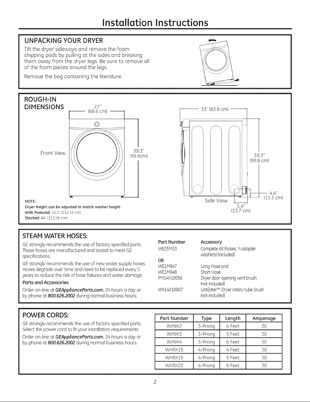
ROUGH-IN
DIMENSIONS
27"
(68.6cm)
©
q
I 33" (83.8 cm)
Front View
NOTE:
Dryer height can be adjusted to match washer height
With Pedestal: 52.1" (152.55 cm)
Stacked: 84" (215.56 cm)
39.3"
(99.8cm)
STEAM WATER HOSES:
GEstrongly recommends the useof factory specified parts.
Thesehosesare manufactured andtested to meet GE
specifications.
GEstrongly recommends the useof new water supply hoses.
Hosesdegrade overtime and need to bereplaced every 5
years to reducethe risk of hose failures and water damage.
Parts and Accessories
Order on-line at GEAppliencePorts.com, 24 hours a day or
by phone at 800.626.2002during normal businesshours.
Part Number
WE25iv153
OR
WE1M847
WEliVt848
plvl14X10056
WX14X10007
39.3"
(99.8 cm)
I 4.4"
Side View
Accessory
CompleteKit(hoses,Y-adapter
washers)(included)
LongHoseand
ShortHose
Dryerdooropeningventbrush
(notincluded)
LintEaterTM Dryerrotarytube brush
(notincluded)
(11.2 cm)
POWER CORDS:
GEstrongly recommends the useof factory specified parts.
Selectthe power cord to fit your installation requirements.
Order on-line at GEApplianceParts.com, 24 hours a day or
by phone at 800.626.2002during normal businesshours.
Part Number Type Length Amperage
WX9X2 3-Prong . 4 Feet . 30
WX9X3 3-Prong 5 Feet 30
WX9X4 3-Prong 6 Feet 30
WX9X18 4-Prong 4 Feet 30
WX9X19 4-Prong 5 Feet 30
WX9X20 4-Prong 6 Feet 30
Page 3
Installation Instructions
REQUIREMENTS FOR ALCOVE OR
CLOSET INSTALLATION
_- Explosion Hazard
Keepflammable materials and vapors, such as gasoline,
away from dryer.
Placedryer at least Z8"(46 cm) above the floor for a
garage installation.
Failureto do so can result in death, explosion, or fire.
, If the dryer is approved for installation in an
alcove or closet, it will be stated on a label on the
dryer back.
, The dryer MUST be vented to the outdoors. See
the EXHAUSTING THE DRYERsection.
, Minimum clearance between dryer cabinet and
adjacent walls or other surfaces is:
0" either side
3" front
3" rear
52" from floor to overhead cabinets
, Consideration must be given to provide adequate
clearance for installation and service.
, Closet ventilation openings required: 2 louvers
each 60 square inches (387 square cm), located 3
inches (7.6 cm) from top and bottom of door.
NOTE: WHEN THE EXHAUST DUCT IS LOCATED AT
THE REAR OF THE DRYER, MINIMUM CLEARANCE
FROM THE WALL iS 5.5 in.
Gas Dryers Only:
, No other fuel burning appliance shall be installed
in the same closet as a gas dryer.
, The dryer must be disconnected from the gas
supply piping during pressure testing at pressures
greater than 1,_psi (3.5 kPa).
, A 1/8 inch NPT minimum plugged tapping,
accessible for test gauge connection, must be
installed immediately upstream of the gas supply
connection to the dryer.
MINIMUM CLEARANCE OTHER THAN
ALCOVE OR CLOSET INSTALLATION
Minimum clearance to combustible surfaces and
for air opening are: O" both sides, 1" front, 3" rear
and 1" top. Consideration must be given to provide
adequate clearance for installation and service.
MOBILE OR MANUFACTURED HOME
INSTALLATION
, Installation must conform to the
MANUFACTURED HOME CONSTRUCTION AND
SAFETYSTANDARD, TITLE 24, PART32-80 or
Standard CAN/CSA-Z240 MH, or, when such
standard is not applicable, with AMERICAN
NATIONAL STANDARD FOR MOBILE HOME,
ANSI/NFPA NO. 50lB.
, The dryer MUST be vented to the outdoors. The
exhaust vent must be securely fastened to a
non-combustible portion of the mobile home.
, The vent MUST NOT be terminated beneath a
mobile or manufactured home.
, The vent duct material MUST BE METAL.
, KIT 14-D346-33 MUST be used to attach the dryer
securely to the structure.
, The vent MUST NOT be connected to any other
duct, vent or chimney.
, Do not use sheet metal screws or other
fastening devices which extend into the interior
of the exhaust vent.
, Provide an opening with a free area of at least
25 square inches for introduction of outside air
into the dryer room.
, See the sections for electrical connection
information.
Page 4
Installation Instructions
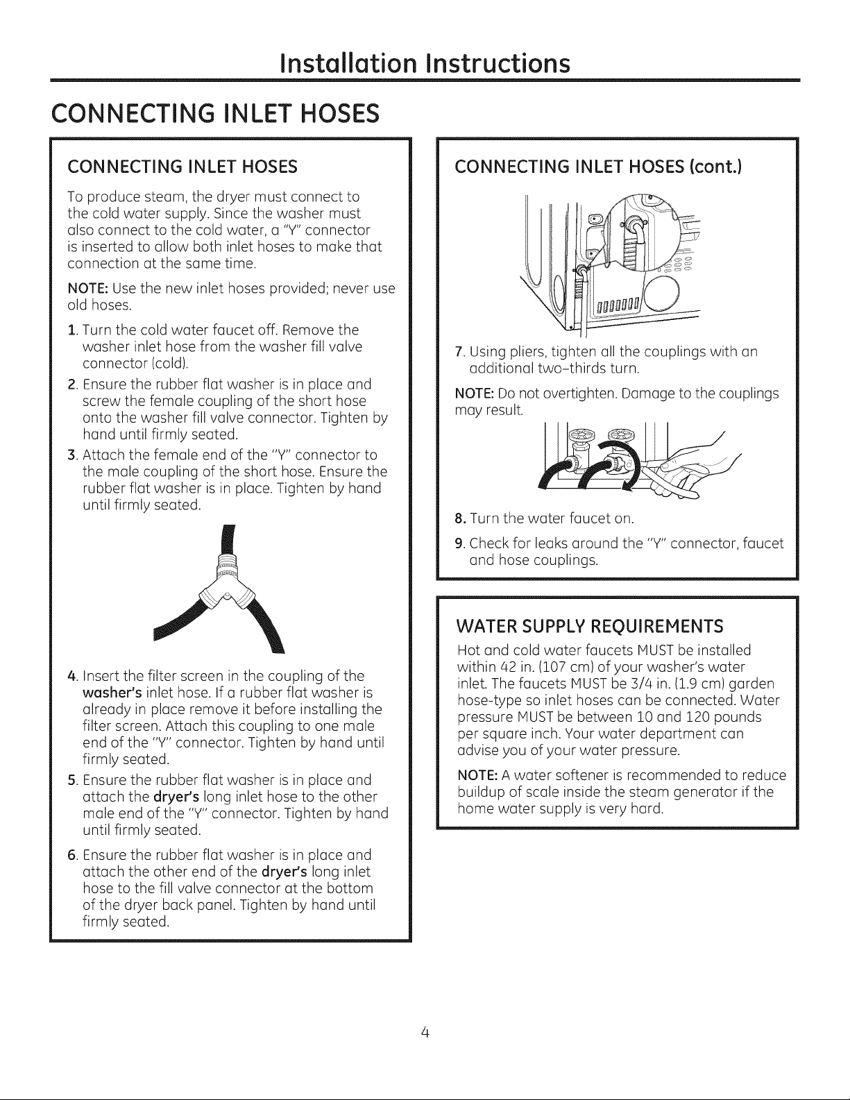
CONNECTING INLET HOSES
CONNECTING iNLET HOSES
To produce steam, the dryer must connect to
the cold water supply. Since the washer must
also connect to the cold water, a "Y" connector
is inserted to allow both inlet hoses to make that
connection at the same time.
NOTE: Use the new inlet hoses provided; never use
old hoses.
. Turn the cold water faucet off. Remove the
washer inlet hose from the washer fill valve
connector (cold).
2. Ensure the rubber flat washer is in place and
screw the female coupling of the short hose
onto the washer fill valve connector. Tighten by
hand until firmly seated.
3. Attach the female end of the "Y" connector to
the male coupling of the short hose. Ensure the
rubber flat washer is in place. Tighten by hand
until firmly seated.
CONNECTING INLET HOSES (cont.)
7. Using pliers, tighten all the couplings with an
additional two-thirds turn.
NOTE: Do not overtighten. Damage to the couplings
may result.
8, Turn the water faucet on.
9. Check for leaks around the "Y" connector, faucet
and hose couplings.
4. Insert the filter screen in the coupling of the
washer's inlet hose. If a rubber flat washer is
already in place remove it before installing the
filter screen. Attach this coupling to one male
end of the "Y" connector. Tighten by hand until
firmly seated.
5. Ensure the rubber flat washer is in place and
attach the dryer's long inlet hose to the other
male end of the "Y" connector. Tighten by hand
until firmly seated.
.
Ensure the rubber flat washer is in place and
attach the other end of the dryer's long inlet
hose to the fill valve connector at the bottom
of the dryer back panel. Tighten by hand until
firmly seated.
WATER SUPPLY REgUIREIENTS
Hot and cold water faucets MUST be installed
within 42 in. (107 cm) of your washer's water
inlet. The faucets MUST be 3/4 in. (1.9 cm) garden
hose-type so inlet hoses can be connected. Water
pressure MUST be between 10 and 120 pounds
per square inch. Your water department can
advise you of your water pressure.
NOTE: A water softener is recommended to reduce
buildup of scale inside the steam generator if the
home water supply is very hard.
Page 5
Installation Instructions
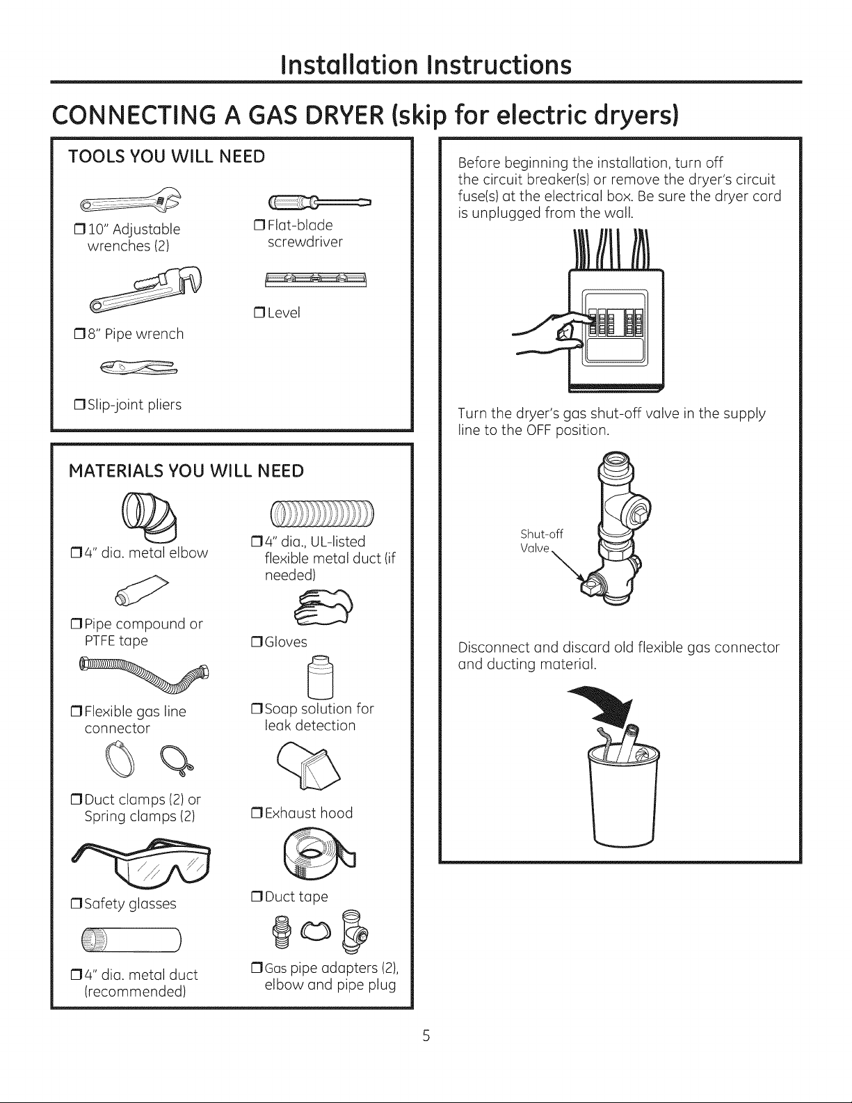
CONNECTING A GAS
TOOLS YOU WILL NEED
17lO" Adjustable
wrenches (2)
178" Pipe wrench
17Slip-joint pliers
MATERIALS YOU WILL NEED
0 Flat-blade
screwdriver
13Level
DRYER(ski
) for electric dryers)
Before beginning the installation, turn off
the circuit breaker(s) or remove the dryer's circuit
fuse(s) at the electrical box. Be sure the dryer cord
is unplugged from the wall.
Turn the dryer's gas shut-off valve in the supply
line to the OFF position.
04" dia. metal elbow
17Pipe compound or
PTFEtape
17Flexible gas line
connector
%
17Duct clamps (2) or
Spring clamps (2)
1:3Safety glasses
174" dia., UL-listed
flexible metal duct (if
needed)
17Gloves
0
C1Soap solution for
leak detection
13Exhaust hood
17Duct tape
Shut-off
Valve
Disconnect and discard old flexible gas connector
and ducting material.
}
04" dia. metal duct
(recommended)
OGas pipe adapters (2),
elbow and pipe plug
Page 6
Installation Instructions
CONNECTING A GAS DRYER (cant,)
GAS REQUIREMENTS
_'- Explosion Hazard
Use a new CSAInternational approved flexible
gas supply line. Never reuse old flexible
connectors.
o
Install a shut-off valve.
o
Securely tighten all gas connections.
o
If connected to LPgas, have a qualified person
make sure gas pressure does not exceed 13"
water column.
. Examples of a qualified person include: licensed
heating personnel, authorized gas company
personnel, and authorized service personnel.
. Failure to do so can result in death, explosion,
or fire.
This gas dryer is equipped with a Valve & Burner
Assembly for use only with natural gas, Using
conversion kit WE25X0217, your local service
organization can convert this dryer for use with
propane (LP)gas. ALL CONVERSIONS MUST BE
MADE BY PROPERLYTRAINED AND QUALIFIED
PERSONNELAND IN ACCORDANCE WITH LOCAL
CODES AND ORDINANCE REQUIREMENTS.
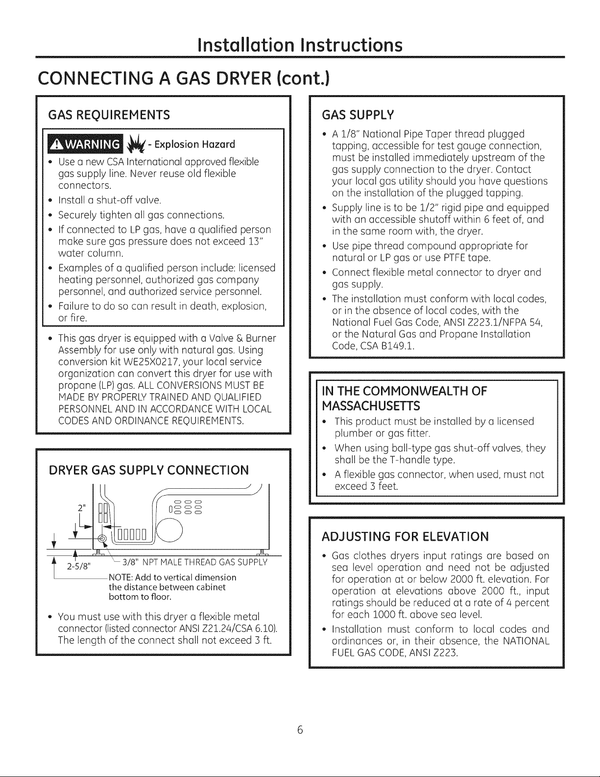
DRYER GAS SUPPLY CONNECTION
GAS SUPPLY
, A 1/8" National Pipe Taper thread plugged
tapping, accessible for test gauge connection,
must be installed immediately upstream of the
gas supply connection to the dryer. Contact
your local gas utility should you have questions
on the installation of the plugged tapping.
, Supply line is to be 1/2" rigid pipe and equipped
with an accessible shutoff within 6 feet of, and
in the same room with, the dryer.
, Use pipe thread compound appropriate for
natural or LP gas or use PTFEtape.
, Connect flexible metal connector to dryer and
gas supply.
, The installation must conform with local codes,
or in the absence of local codes, with the
National Fuel Gas Code, ANSI Z223.1/NFPA 54,
or the Natural Gas and Propane Installation
Code, CSA B149.1.
IN THE COMMONWEALTH OF
MASSACHUSETTS
,, This product must be installed by a licensed
plumber or gas fitter.
. When using ball-type gas shut-off valves, they
shall be the T-handle type.
. A flexible gas connector, when used, must not
exceed 3 feet.
2 !!
t5/8"
. You must use with this dryer a flexible metal
connector (listed connector ANSI Z21.24/CSA 6.10).
The length of the connect shall not exceed 3 ft.
"- 3/8" NPT MALETHREAD GAS SUPPLY
NOTE:Add to vertical dimension
the distance between cabinet
bottom to floor.
ADJUSTING FOR ELEVATION
Gas clothes dryers input ratings are based on
sea level operation and need not be adjusted
for operation at or below 2000 ft. elevation. For
operation at elevations above 2000 ft., input
ratings should be reduced at a rate of 4 percent
for each 1000 ft. above sea level.
Installation must conform to local codes and
ordinances or, in their absence, the NATIONAL
FUEL GAS CODE, ANSI Z223.
Page 7
Installation Instructions
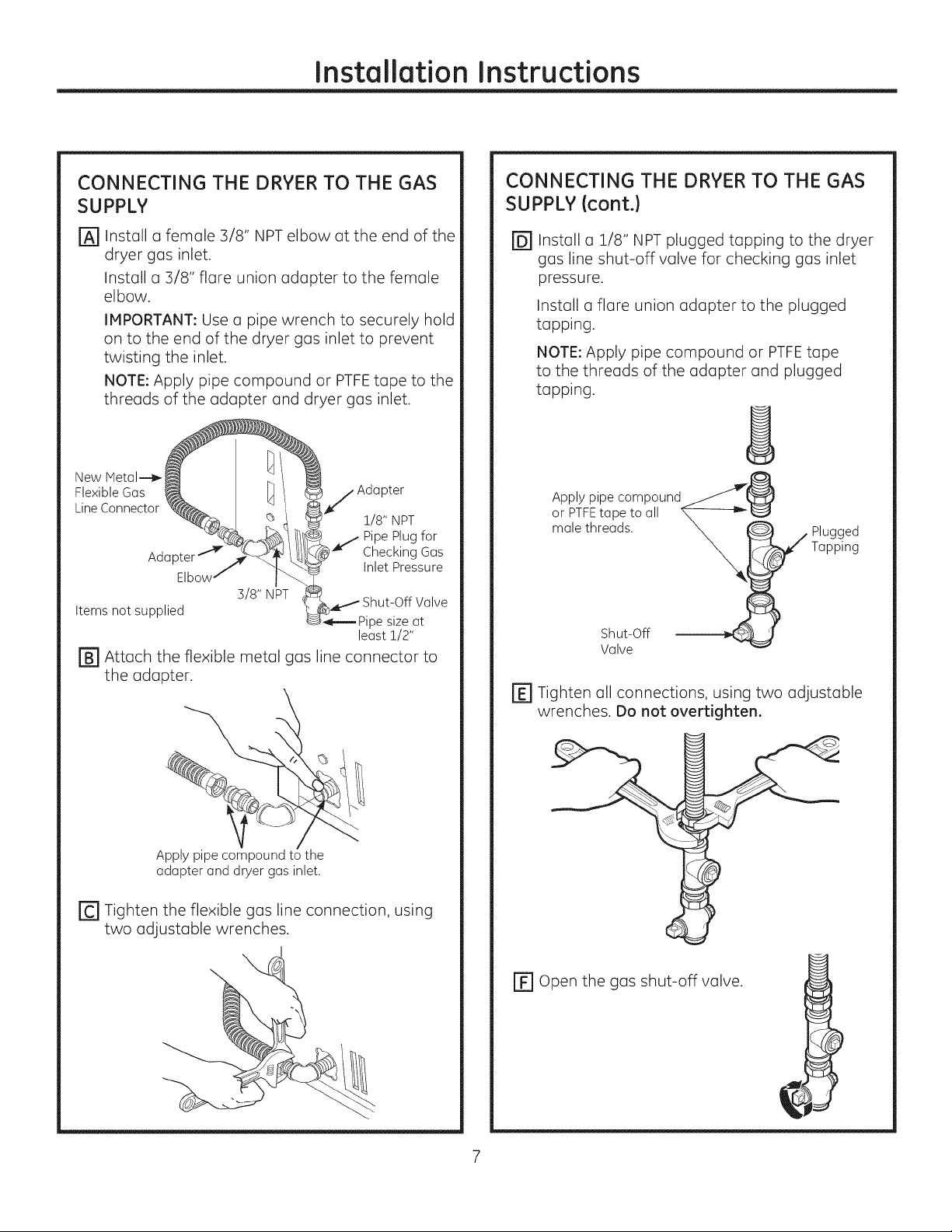
CONNECTING THE DRYER TO THE GAS
SUPPLY
Install a female 3/8" NPT elbow at the end of the
@
dryer gas inlet.
Install a 3/8" flare union adapter to the female
elbow.
IMPORTANT: Use a pipe wrench to securely hold
on to the end of the dryer gas inlet to prevent
twisting the inlet.
NOTE: Apply pipe compound or PTFEtape to the
threads of the adapter and dryer gas inlet.
New Metal--_ /
Flexible Gas
Line Connector _g'_@Q
Elbowj
Adapter _ _i
Items not supplied
r_ Attach the flexible metal gas line connector to
the adapter.
j Adapter
1/8" NPT
J Checking Gas
Pipe Plug for
Inlet Pressure
l_kl- Shut-Off Valve
-,_--- Pipe size at
least 1/2"
CONNECTING THE DRYERTO THE GAS
SUPPLYIcont.}
@Install a 1/8" NPT plugged topping to the dryer
gas line shut-off valve for checking gas inlet
pressure.
Install a flare union adapter to the plugged
topping.
NOTE: Apply pipe compound or PTFEtope
to the threads of the adapter and plugged
topping.
oArPPITYFPitPe;°tm Pa_und_0
male threads. __ W PlaUp_1_dg
r_ Tighten all connections, using two adjustable
wrenches. Do not overtighten.
Apply pipe compound to the
adapter and dryer gas inlet.
r_ Tighten the flexible gas line connection, using
two adjustable wrenches.
EF1Open the gas shut-off valve.
Page 8
Installation Instructions
CONNECTING A GAS DRYER (cont.)
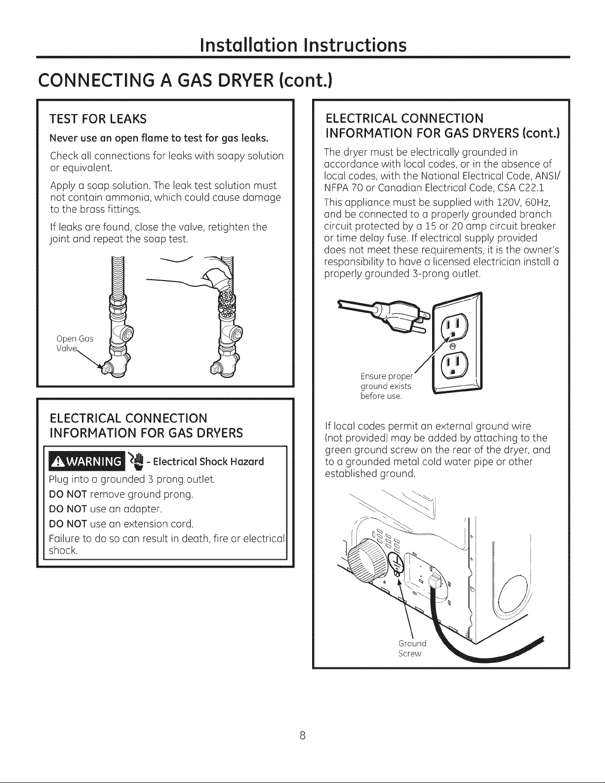
TEST FOR LEAKS
Never use an open flame to test for gas leaks.
Check all connections for leaks with soapy solution
or equivalent.
Apply a soap solution. The leak test solution must
not contain ammonia, which could cause damage
to the brass fittings.
If leaks are found, close the valve, retighten the
joint and repeat the soap test.
Open Gos
ELECTRICAL CONNECTION
INFORMATION FOR GAS DRYERS (cont.}
The dryer must be electrically grounded in
accordance with local codes, or in the absence of
local codes, with the National Electrical Code, ANSI/
NFPA 70 or Canadian Electrical Code, CSA C22.1
This appliance must be supplied with 120V, 60Hz,
and be connected to a properly grounded branch
circuit protected by a 15 or 20 amp circuit breaker
or time delay fuse. If electrical supply provided
does not meet these requirements, it is the owner's
responsibility to have a licensed electrician install a
properly grounded 3-prong outlet.
Ensure proper
ground exists
before use.
ELECTRICAL CONNECTION
INFORMATION FOR GAS DRYERS
_,dL
_ - Electrical Shock Hazard
i
Plug into a grounded 3 prong outlet.
DO NOT remove ground prong.
DO NOT use an adapter.
DO NOT use an extension cord.
Failure to do so can result in death, fire or electrical
shock.
If local codes permit an external ground wire
(not provided) may be added by attaching to the
green ground screw on the rear of the dryer, and
to a grounded metal cold water pipe or other
established ground.
Ground
Screw
Page 9
Installation Instructions
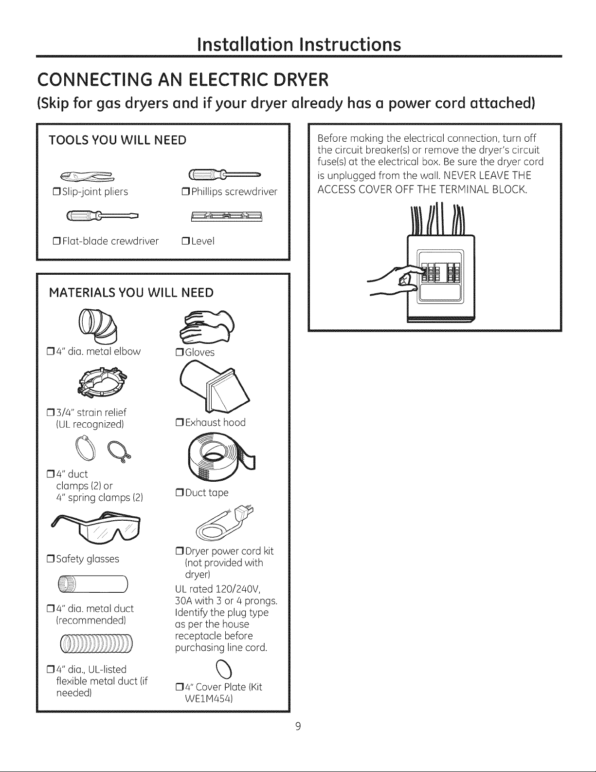
CONNECTING AN ELECTRIC DRYER
(Skip for gos dryers ond if your dryer olreody hos o power cord ottoched)
TOOLS YOU WILL NEED
C1Slip-joint pliers 17Phillips screwdriver
17Flat-blade crewdriver 17Level
MATERIALS YOU WILL NEED
174" dia. metal elbow
173/4" strain relief
IUL recognized)
17Gloves
0 Exhaust hood
Before making the electrical connection, turn off
the circuit breaker(s) or remove the dryer's circuit
fuse(s) at the electrical box. Be sure the dryer cord
is unplugged from the wall. NEVER LEAVE THE
ACCESS COVER OFF THE TERMINAL BLOCK.
04" duct
clamps (2)or
4" spring clamps (2)
0 Safety glasses
04" dia. metal duct
(recommended)
174" dia., UL-listed
flexible metal duct (if
needed)
17Duct tape
17Dryer power cord kit
(not provided with
dryer)
)
UL rated 120/240V,
30A with 3 or 4 prongs.
Identify the plug type
as per the house
receptacle before
purchasing line cord.
(5
174" Cover Plate (Kit
WE1H454)
Page 10
Installation Instructions
CONNECTING AN
ELECTRICDRYER{cont.}
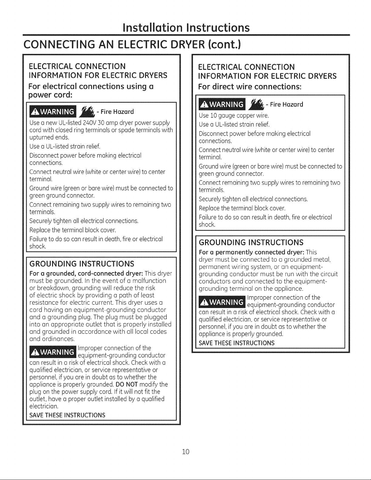
ELECTRICAL CONNECTION
INFORMATION FOR ELECTRIC DRYERS
For electrical connections using a
power cord:
- Fire Hazard
Use a new UL-listed 240V 30 amp dryer power supply
cord with closed ring terminals or spade terminals with
upturned ends.
Use a UL-listed strain relief.
Disconnect power before making electrical
connections.
Connect neutral wire (white or center wire) to center
terminal.
Ground wire (green or bare wire) must be connected to
green ground connector.
Connect remaining two supply wires to remaining two
terminals.
Securely tighten all electrical connections.
Replace the terminal block cover.
Failure to do so can result in death, fire or electrical
shock.
GROUNDING INSTRUCTIONS
For a grounded, cord-connected dryer: This dryer
must be grounded. In the event of a malfunction
or breakdown, grounding will reduce the risk
of electric shock by providing a path of least
resistance for electric current. This dryer uses a
cord having an equipment-grounding conductor
and a grounding plug. The plug must be plugged
into an appropriate outlet that is properly installed
and grounded in accordance with all local codes
and ordinances.
Improper connection of the
equipment-grounding conductor
can result in a risk of electrical shock. Check with a
qualified electrician, or service representative or
personnel, if you are in doubt as to whether the
appliance is properly grounded. DO NOT modify the
plug on the power supply cord. If it will not fit the
outlet, have a proper outlet installed by a qualified
electrician.
SAVE THESE INSTRUCTIONS
ELECTRICAL CONNECTION
INFORMATION FOR ELECTRIC DRYERS
For direct wire connections:
- Fire Hazard
Use 10 gauge copper wire.
Use a UL-listed strain relief.
Disconnect power before making electrical
connections.
Connect neutral wire (white or center wire) to center
terminal.
Ground wire (green or bare wire) must be connected to
green ground connector.
Connect remaining two supply wires to remaining two
terminals.
Securely tighten all electrical connections.
Replace the terminal block cover.
Failure to do so can result in death, fire or electrical
shock.
GROUNDING INSTRUCTIONS
For a permanently connected dryer: This
dryer must be connected to a grounded metal,
permanent wiring system, or an equipment-
grounding conductor must be run with the circuit
conductors and connected to the equipment-
grounding terminal on the appliance.
Improper connection of the
equipment-grounding conductor
can result in a risk of electrical shock. Check with a
qualified electrician, or service representative or
personnel, if you are in doubt as to whether the
appliance is properly grounded.
SAVETHESEINSTRUCTIONS
10
Page 11

Installation Instructions
CONNECTING DRYER USING 4-WIRE
CONNECTION (MUST BE USED FOR
MOBILE HOME INSTALLATION)
NOTE:Since January !, !996, the National Electrical Code
requires that new constructions use a 4-wire connection
to an electric dryer. A 4-wire cord must also be used where
local codes do not permit grounding through the neutral.
S-wire connection is NOTfor use on new construction.
Wire according to the terminal block illustration that
matches your dryer: Relocatre
HotWire Screw Wire screwhere minimum
Screw \ __ J /conductors
X._ \ I copper
Remove
groundstrap _-,_/_'_"__=======_"_'_\ \ / 30Apower
anddiscard._'<._J.J_"._] ]_/_ supplycordkit
Keepgreen _ K-']) markedfor use
ground Neutral t'l_ ,_--_----------_------_7-T1L17-Ywith dryers
screw. (white) y\ f_ / ._/ andprovided
/\
HotWire loop or spade
Screw_\" Hot W_e screwneregreenground WireGreenminimum
Scre,,, _ _ -'_--\_/ / conductors
Remove __.,_/-'<_ _'_X_/_ /or !20/240V
ground strap_<'_o; _ _'€_ _ \/30A power
anddiscard._i-_ __ supplycordkit
Keep green _ __Jr:t-I-_ marked for use
ground Neutral / ]_, _ \V _! ! with dryers
screw. (white)_Q L_/_/___'_ / with closed
Screw_ / / _" loop or spade
HotWire Recognized Relief upturnedends
1. Turn off the circuit breaker(s) (30 amp) or remove the
dryer's circuit fuse at the electrical box.
2. Be sure the dryer cord is unplugged from the wall
receptacle.
3. Removethe power cord cover located at the lower back.
4. Remove and discard ground strap. Keep the green
ground screw for Step 7.
5. Install 3/4 in. UL-recognized strain relief to power cord
entry hole. Bring power cord through strain relief.
6. Connect power cord as follows:
A. Connect the 2 hot lines to the outer screws of the
terminal block (marked L! and L2).
B.Connect the neutral (white) line to the center of the
terminal block (marked N).
7. Attach ground wire of power cord with the green
ground screw (hole above strain relief bracket). Tighten
all terminal block screws (3)securely.
8. Properly secure power cord to strain relief.
9. Reinstall the cover.
NEVER LEAVE THE COVER OFF OF THE TERMINAL
BLOCK.
Green green ground 4#!OAWG
/or !20/240V
[- __SYtrain with closed
3/4" UL Relief terminalswith
Screw RecognizedBracket upturnedends
StrainRelief (notsupplied)
Relocatre 4 #!0 AWG
X / copper
_7"_, \J / and provided
3/4" UL Strain terminals with
StrainRelief Bracket (notsupplied)
CONNECTING DRYER USING 3-WIRE
CONNECTION
If required, by local code, install external ground (not
provided) to grounded metal, cold water pipe, or other
established ground determined by a qualified electrician.
Wire according to the terminal block illustration that
matches your dryer:
Hot Wire Screw
Screw_ \f_/ /minimum copper
Ground, _ _J _ _ /conductors or
Strap '_(_==]]]]_Zv__--__ X'_ / !20/240V30A
Green _-_",_L---'___,_i_i_)*,,Hl_s powersupplycord
. _..,,,-'_,__11 I "() kit marked for
grouna_ IJ_'; _- , , }} _Jl_--_ _' .
screw _,_ ._r_ _'/ _// use with dryers
Neutralf /\\/ /__]" _ a,ndprovidedwith
(white) / \/" m/_l" c,osea,oopor
/ __/. 3/#'ULt Strain spadeterminals
Hot Wire _crew Recognized Relief withupturned
Screw Hot Wire
Ground
Strap
Green
ground
screw
(white)
Screw Hot 3/a" UL Strain
3-wire Connection
Not for use in Canada.
DO NOT use for Mobile Home Installations.
NOT for use on new construction.
NOT for use on recreational vehicles.
Wire Recognized Relief
NOTfor use in areas where local codes prohibit
grounding through the neutral conduction.
1. Turn off the circuit breaker(s) (30 amp) or remove the
dryer's circuit fuse at the electrical box.
2. Be sure the dryer cord is unplugged from the wall
receptacle.
3. Remove the power cord cover located at the lower
back.
4. Install 3/4-in. UL-recognized strain relief to power cord
entry hole. Bring power cord through strain relief.
5. Connect power cord as follows:
A. Connect the 2 hot lines to the outer screws of the
terminal block (marked L! and L2).
B. Connect the neutral (white) line to the center of the
terminal block (marked N).
6. Be sure ground strap is connected to neutral (center)
terminal of block and to green ground screw on cabinet
rear. Tighten all terminal block screws (3)securely.
7. Properly secure power cord to strain relief.
8. Reinstall the cover.
NEVER LEAVE THE COVER OFF OF THE TERMINAL
BLOCK.
11
/ 3#!0 AWG
StrainRelief Bracket ends(notsupplied)
3 #!0 AWG
.minimum copper
conductors or
!20/2aov 30A
power supply cord
kit marked for
use with dryers
and provided with
closed loop or
spade terminals
with upturned
Strain Relief Bracket
ends (not supplied)
Page 12

Installation Instructions
EXHAUSTING THE DRYER
- Fire Hazard
This dryer MUST be vented to the outdoors.
Use only 4" rigid metal ducting for the home
exhaust duct.
Use only 4" rigid metal or UL-listed dryer transition
duct to connect the dryer to the home exhaust.
DO NOT use a plastic vent.
DO NOT exhaust into a chimney, kitchen exhaust,
gas vent, wall, ceiling, attic, crawl space, or
concealed space of a building.
DO NOT install a screen in or over the exhaust duct.
DO NOT use duct longer than specified in the
exhaust length table.
Failure to follow these instructions can result in
death or fire.
TOOLS AND MATERIALS YOU WILL
NEED TO INSTALL EXHAUST DUCT
17Phillips-head 17Drill with 1/8" drill bit
screwdriver (for bottom venting)
17Hacksaw
17Duct tape or duct
clamp
0 Rigid or UL-listed C1Vent hood
flexible metal 4"
(10.2 cm) duct
CONNECTING THE DRYER TO HOUSE
VENT
RIGID METALTRANSITIONDUCT
• Forbest drying performance, a rigid metal transition
duct isrecommended.
• Rigidmetal transition ducts reduce the risk of crushing
and kinking.
UbLISTED FLEXIBLEMETAL(SEMI-RIGID)TRANSITION
DUCT
• If rigid metal duct cannot be used, then UL-listed
flexible metal (semi-rigid)ducting can be used (Kit
WX08X10077).
• Never install flexible metal duct in walls, ceilings, floors
or other enclosed spaces.
• Total length of flexible metal duct should not exceed 7'
9"12.4m).
• Formany applications, installing elbows at both
the dryer and the wall is highly recommended (see
illustrations at right). Elbows allow the dryer to sit
close to the wall without kinking and/or crushing the
transition duct, maximizing drying performance.
• Avoid resting the duct on sharp objects.
UL.-LISTEDFLEXIBLEMETAL (FOIL-TYPE)TRANSITION
DUCT
• Inspecial installations, it may be necessary to connect
the dryer to the house vent using a flexible metal
(foil-type) duct. A UL-listed flexible metal (foil-type)duct
may be used ONLYin installations where rigid metal or
flexible metal (semi-rigid) ducting cannot beused AND
where a 4" diameter can be maintained throughout
the entire length of the transition duct.
• Only the flexible metal (foil-type) ducts that comply with
the "Outline for Clothes Dryer Transition Duct Subject
2158A" shall be used.
Never install flexible metal duct inwalls, ceilings, floors
or other enclosed spaces.
Total length of flexible metal duct should not exceed 7'
9"12.4m).
o
Avoid resting the duct on sharp objects.
o
Forbest drying performance:
1.Slide one end of the duct over the clothes dryer
outlet pipe.
2.Secure the duct with aclamp.
]. With the dryer in its permanent position, extend
the duct to its full length. Allow 2" of duct to
overlap the exhaust pipe. Cut off and remove
excess duct. Keep the duct as straight as
possible for maximum airflow.
4.Secure the duct to the exhaust pipe with the
other clamp.
12
Page 13

Installation Instructions
,DO cut duct as short
as possible and install
straight into wall.
• DO NOT bend
or collapse
ducting. Use
elbows if turns
are necessary.
•DO NOT use
excessive
exhaust
length. Cut
duct as short
as possible.
EXHAUST LENGTH
Using exhaust longer than specified length will:
, Increase the drying times and the energy cost.
, Reduce the dryer life.
, Accumulate lint, creating a potential fire
hazard.
The correct exhaust installation is YOUR
RESPONSIBILITY.
Problems due to incorrect installation are not
covered by the warranty.
,DO use elbows when
turns are necessary.
Elbows
• DO NOT _,DO NOT
against the on duct.
wall.
crush duct _..... set dryer
The MAXIMUM ALLOWABLE length of the exhaust
system depends upon the type of duct, number of
turns, the type of exhaust hood (wall cap) and all
conditions noted on the chart.
, Internal elbows added for side or bottom vent
conversions must be included in the total elbow count.
, Any elbow greater than 45 ° should be treated as a
90 ° elbow.
, Two 45° elbows will be treated like one 90° elbow.
, For every additional 90 ° elbow, reduce the allowable
vent system length by 10 feet.
, The total vent system length includes oil the straight
portions and elbows of the system (transition duct
included).
EXHAUST LENGTH
FOR NORMAL VENT MODELS
RECOMMENDEDMAXIMUMLENGTH
Exhaust Hood Types
Recommended
I
I
NO. of 90° Rigid Rigid
Elbows Metal Metal
0 90 Feet 60 Feet
i 60 Feet 45 Feet
2 45 Feet 35 Feet
3 35 Feet 25 Feet
4 25 Feet 15 Feet
Use only for short
run installations
4" DIA.
--_ 1_2-1/2 -
EXHAUST LENGTH
FOR LONG VENT MODEL - GFDLllO
RECOMMENDED MAXIMUM LENGTH
ExhoustHood Types
Use only for short
4" DIA.
Rigid
Metol
175 Feet
165 Feet
155 Feet
145 Feet
135 Feet
125 Feet
No. of 90 °
Elbows
0
1
2
3
4
5
Recommended run instQIIotions
_1 /4"
Rigid
Metal
200 Feet
185 Feet
175 Feet
165 Feet
155 Feet
145 Feet
1]
Page 14

Installation Instructions
EXHAUSTING THE DRYER(cont.)
EXHAUST SYSTEM CHECKLIST
HOOD ORWALL CAP
• Terminate ina manner to prevent back drafts or entry
of birds or other wildlife.
Termination should present minimal resistance to
the exhaust airflow and should require little or no
maintenance to prevent clogging.
Wall caps must be installed at least 12" above ground
level or any other obstruction with the opening
pointed down.
• Never vent the dryer out of the roof.
SEPARATIONOFTURNS
• For best performance, separate all turns by at least
4 ft. of straight duct, including distance between last
turn and dampened wall cap.
SEALINGOFJOINTS
• Alljoints should be tight to avoid leaks.The male end
of each section of duct must point away from the
dryer.
• Duct joints should be made air- and moisture-tight
by wrapping the overlapped joints with duct tape or
aluminum tape.
Do not assemble ductwork with any fasteners
that extend into the duct. These fasteners can
accumulate lint, creating a potential fire hazard.
Horizontal runs should slope down towards the
outdoors 1/4" per foot.
Providean accessfor inspection and cleaning of
the exhaust system,especiallyat turns and joints.
Exhaustsystem shall be inspected and cleanedat
least once ayear.
INSULATION
• Ductwork that runs through an unheated area or is
near air conditioning should be insulated to reduce
condensation and lint buildup.
BEFORE YOU BEGIN
STANDARD REAR EXHAUST
We recommend that you install your dryer before
installing your washer. This will permit direct
access for easier exhaust connection.
Slide the end of the exhaust duct on the back of the
dryer and secure with duct tape or a hose clamp.
/'
NOTE: We strongly recommend using rigid metal
exhaust duct.
For straight-line installation, connect the dryer
exhaust to the wall, using duct tape.
all Side
Dryer
Side
RECOMMENDED CONFIGURATION TO
MINIMIZE EXHAUST BLOCKAGE
Using duct elbows will prevent duct kinking
collapsing.
and
, Remove and discard existing plastic or metal foil
duct and replace with UL-listed duct.
, Remove any lint from the wall exhaust opening.
Wall
Internal
Duct
Check that exhaust
hood damper opens
and closes freely.
Transitior
Ducting --
14
Page 15

Installation Instructions
SIDE OR BOTTOM VENTING
Dryer Exhaust to right of cabinet for Electric
models only.
Dryer Exhaust to left of cabinet for Gas and
Electric models.
Dryer Exhaust to the bottom of cabinet for
Gas and Electric models.
- Fire Hazard
Close the back opening with cover plate (Kit
WE1M454).
Disconnect dryer from electrical supply.
Wear gloves and arm guards.
Failure to do so may result in fire, electrical shock
or lacerations.
Remove
screw Right
and save (electric
models
nly)
Left
Bottom
Remove desired
knockout (one only)
Detach and remove the right (electric models only),
left or bottom knockout as desired. Remove the
screw inside the dryer exhaust duct and save. Pull
the duct out of the dryer.
Fixing hole
]_3Y/' (34.29cm)
Cut the duct as shown and keep portion A.
TAB LOCATION
Not for gas
Bend tab
Through the rear opening, locate the tab in the
middle of the appliance base. Lift the tab to about
45°,using a flat-blade screwdriver.
ADDING A NEW DUCT
Fixing Portion "A"
hole
Left side
exhaust
Reconnect the cut portion (A)of the duct to the
blower housing. Make sure that the shortened
duct is aligned with the tab in the base. Use the
screw saved previously to secure the duct in place
through the tab on the appliance base.
ADDING ELBOW AND DUCT FOR EXHAUST TO
LEFT OR RIGHT SIDE OF CABINET
Exhaust can 4..........._-.._"-_-"
be added to
left or right _. t
models tape
only) side , -J
(electric li__
, Preassemble 4" elbow with 4" duct. Wrap duct
tape around joint.
, Insert duct assembly, elbow first, through the
side opening and connect the elbow to the dryer
internal duct.
Be sure not to pull or damage the electrical wires
inside the dryer when inserting the duct.
15
Page 16

Installation
Instructions
EXHAUSTINGTHE
DRYER{cont.}
SIDE OR BOTTOM VENTING (cant,}
ADDING ELBOW AND DUCT FOR EXHAUST TO
LEFT OR RIGHT SIDE OF CABINET {cont.}
, Apply duct tape as
shown on thejoint
between the dryer
internal duct and the
elbow, and also the joint
between the elbow and
the side duct.
Use 4" rigid metal ducting only inside the dryer.
Internal duct joints must be secured with tape,
otherwise they may separate and cause a safety
hazard.
ADDING ELBOW FOR EXHAUST THROUGH
BOTTOH OF CABINET
, Insert the elbow through the rear opening and
connect it to the dryer internal duct.
, Apply duct tape as Duct t(]pe
shown on the joint
between the dryer
internal duct and the
elbow, and also the
joint between the
elbow and the bottom
duct.
Internal duct joints must be secured with tape;
otherwise, they may separate and cause a safety
hazard.
DUCT
TAPE
FINAL SETUP
I]] LEVEL THE DRYER
Stand the dryer upright near the final location and
adjust the four leveling legs at the corners to ensure
that the dryer is level from side to side and front to
rear.
ITI PLUG DRYER IN
Ensure proper
ground exists
before use.
ADDING COVER PLATE TO REAR OF CABINET
:,"') _J
Plate __
(Kit WE1M454)
Connect standard metal elbows and ducts to
complete the exhaust system. Cover back opening
with a plate (Kit WE1P1454) available from your
local service provider. Place dryer in final location.
NEVER LEAVE THE BACK OPENING WITHOUT THE
PLATE. (Kit WEl1454.)
[_] DRYER START-UP
Press the Power button.
Power
NOTE: If the dryer has been exposed to
temperatures below freezing for an extended
period of time, allow it to warm up before pressing
Power. Otherwise, the display will not come on.
The dryer is now ready for use.
16
Page 17

Instrucciones
S
d
de i stal Ci°
j Si tiene alguna pregunta, flame a 800.GE.CARES (800.432.2737) o visite nuestro sitio Web en: GEAppliances.com i
A Estees el s[mbolo dealerta de seguridad. Elmismo alerta sabre potenciales riesgos que le pueden producir la muerte
o lesiones tanto austed come a otras personas. Todos los mensajes de seguridad estarcin a continuaci6n del s[mbolo
de alerta de seguridad y con la palabra "PELIGRO","ADVERTENCIA"o "PRECAUCION".Estaspalabras se definen come:
Indica una situaci6n de riesgo que,si no se evita, producir6 la muerte o lesionesgraves.
Indica una situaci6n de riesgo qua,si no se evita, podriu producir la muerte o lesiones graves.
_ Indica una situaci6n de riesgo qua,si no se evita, podriu resultar en lesionesmenores o moderadas.
ANTES DE COMENZAR
Leo estos instrucciones par complete y con
detenimiento.
• IM PORTANTE-Guardeestasinstrucciones
pareelusede inspectoresel@ctricoslocales.
•IMPORTANTE- cumplacontodoslos
c6digosy ordenanzasvigentes.
• Instalelasecadorade acuerdo con lasinstrucciones
del fabricante y los c6digos locales.
• Nota al instolodor- AsegOrese de dejar estas
instrucciones con el consumidor.
Note ol usuario - Conserveestas instrucciones para
referencia futura.
Lainstalaci6n de la secadoradebeefectuarla un
instalador calificado.
o
Esta secadora debe tener una salida al exterior.
o
Antesde que la secadora antigua searetirada del
servicioo eliminada,qdtele la puerto.
Lainformaci6n sabre reparaciones y el diagrama del
cableado seencuentran enla consoladecontrol.
• No permita que niBos se suban o se metan dentro
del artefacto. Se requiere una supervisi6n estricta
cuando el aparato es utilizado cerca de nines.
• El instalador tiene la responsabilidad de efectuar una
instalaci6n adecuada.
Lagarant[a no cubrelos folios del producto debido a
una instalaci6n incorrecta..
Instale la secadoraen lugaresdonde latemperatura
seamayor a 50°Fpara un funcionamiento
satisfactorio del sistema de control de la secadora.
Quite y descarte el conducto existente de plcistico
o de papal de aluminio y coloque un conducto
aprobado per UL
_#_- Riesgo de incendio
, Lainstalaci6n de la secadora debe efectuarla un
instalador calificado.
Instale la secadora de ropa de acuerdo con estas
instrucciones yen cumplimiento con los c6digos
locales
, NO instale una secadora de ropa con conductos
de plc_sticoflexible. Si se instala un conducto
flexible de metal (semi rigido o de tipo papel de
aluminio), debe astor aprobado per UL e instalarse
de acuerdo con las instrucciones de "C6mo
conectar la secadora a la ventilaci6n dom#stica"
de este manual. Los materiales de los conductos
flexibles a menudo se desploman, se aplastan y
atrapan pelusas. Estas condiciones obstruyen la
corriente de aire de la secadora e incrementan el
riesgo de incendio.
, NO instale o almacene este aparato en un
lugar donde se vea expuesto al agua o a los
inclemencias del tiempo.
, Para reducir el riesgo de una lesi6n grave o de
muerte, cumpla con todas los instrucciones de
instalaci6n.
Guarde estas instrucciones. (Instaladores:
Aseg0rense de dejar estas instrucciones al
consumidor).
IIIIIII11111111IIIIIIIIIMIIIIIIIIIIII
234D2274P001
31-16748 o4-14 GE
Page 18

Instruccionesde instalaci6n
COMO DESEMPACAR LA SECADORA
Incline la secadora de costado y saque los patios de espuma
de embalaje tirando de los costados y quitdndolos de las
patas de la secadora. Aseg0rese de quitar todas las piezas
de espuma de las patas.
Saque la bolsa que contiene la informaci6n.
DIMENSIONES
APROXIMADAS
I
27"
(68,6 cm) --
I
©
I 33" (83,8 cm) I
Visi6n frontal
NOTE :
La altura de la secadora puede ser ajustada para quedar a la misma a altura
de la lavadora
Con pedestal: 52.1" (152,55 cm)
Apilada: 84" (213.36 cm)
39.3"
(99,8cm)
MANGUERA DE VAPOR ¥ AGUA:
GE recomienda enf6ticamente el uso de piezas especfficas
de f6brica. A continuaci6n figura una lista de mangueras
de fabricas que podr6 adquirir. Dichas mangueras son
fabricadas y probadas de modo que se cubran las
especificaciones de GE.
GErecomienda enf6ticamente el usode nuevas mangueras
de suministro de agua. Con el paso del tiempo, las mangueras
sedegradas y deben set reemplazadas cada 5 ahos, a fin de
reducir el riesgode fallas sobre lasmismas y dahos con el agua.
Piezas y Accesorios
Ordenehoy a trav6sde Internet en GEAppliancesparts.cam,
las 24 horas del dia o en forma telef6nica Ilamando al
800.525.2002, durante el horario comercial habitual.
NOmerode Pieza
WE25M53
O
WEliV1847
WEliVt848
PM14X10056
puerto
incluido)
WXl4Xl0007
39,3"
(99,8 cm)
Visi6n lateral
Accesorio
KitCompleto(mangueras,lavadoracon
adaptadorenY)(incluido)
MangueraLargay
MangueraCorta
Cepillodeventilaci6ndelaaberturadela
delasecadora(no
CepillocontuberfagiratoriaLintEaterTM (no
incluido)
CABLES DE CORRIENTE:
GErecomienda enf6ticamente el usode piezasespecfficasde
f6brica. Seleccioneel cable de corriente que seadec0e a sus
requisitos de instalaci6n.
Ordene a trav6s deInternet en GEAppliancesParts.cam, las24
horas del diaoen forma telef6nica Ilamando a1800.626.2002,
durante elhorario comercial habitual.
Pieza N° Tipo Longitud Amperios
WX9X2 3IClavUas 4 Pies 30
WX9X3 3-ClavUas 5 Pies 30
WX9X4 3IClavUas 6 Pies 30
W×9×18 4-ClavUas 4 Pies 30
w×9×19 4-ClavUas g Pies 30
w×9×20 4-ClavUas 6 Pies 30
2
Page 19

Instruccionesde instalaci6n
REOUERIMIENTOS PARA INSTALACI6N
EN NICHOS O ARMARIOS
_ _'- Riesgode explosi6n
lViantengacualquiermaterial y vaporesinflamables,
talescomo gasolina,alejadosdela secadora.
Coloque la secadora a por Io menos 18"(46 cm.)del
piso cuando sea instalada en un garaje.
si nosecumplecon esto,se podr6 produciruna
explosi6n,incendioo la muerte.
, Si se aprob6 la instalaci6n de su secadora en
alcoba o armario, esto figurar6 en una etiqueta
en el reverso de la secadora.
, Esta secadora DEBEtener una ventilaci6n
al exterior. Ver la secci6n SALIDA AL EXTERIOR
DE LA SECADORA.
Elespacio libre minimo entre el armario
de la secadora y las paredes adyacentes
u otras superficies es:
0" sobre ambos lados
3" sobre el frente
3" sobre el la parte trasera
52" desde la puerta hasta los gabinetes
sobre 6sta
, Se deber6 considerar que se debe brindar el
despeje adecuado para la instalaci6n y el servicio
t6cnico.
, Se requiere la apertura de la ventilaci6n en
armarios: 2 celosias, cada una de 60 pulgadas
cuadradas (387 cm. cuadrados) ubicadas a 3
pulgadas (7.6 cm.) desde la parte superior e
inferior de la puerta.
NOTA: CUANDO EL CONDUCTO DE SALIDA EST#,
UBICADO EN LA PARTETRASERA DE LA SECADORA,
EL ESPACIO LIBRE MiNIMO DESDE LA PARED DEBE
SER 5.5 PULGADAS.
Secadoras a Gas Onicamente:
• No se deber6 instalar ning0n otro electrodom@stico
que consuma combustible en el mismo armario
donde haya una secadora a gas.
• La secadora se deber6 desconectar de la tuberia de
suministro de gas durante la prueba de presi6n en
presiones superiores a !4 psi (3.5 kPa).
, Una rosca cubierta NPT de 1/8", accesible para
la conexi6n de un dispositivo de calibraci6n,
deber6 ser instalada inmediatamente arriba de la
conexi6n del suministro de gas a la secadora.
ESPACIO LIBRE MINIMO EN OTROS
ESPACIOS QUE NO SEAN INSTALACIONES
EN NICHOS O ARMARIOS
Los espacios libres minimos respecto de superficies
combustibles y de aberturas de aire son: 0" a
ambos lados, 1" (25.4mm) en el frente, 3" (75mm)
en la parte trasera y 1" (25.4mm) superior. Debe
tenerse en cuenta un espacio libre adecuado para
un funcionamiento y reparaci6n correctos.
INSTALACI6N EN CASAS M6VILES
O PREFABRICADAS
Instalaci6n debe cumplir con la NORMA
SOBRE CONSTRUCCION Y SEGURIDAD DE CASAS
PREFABRICADAS,TiTULO 24, PARTE32-80 o
Norma CAN/CSA-Z240 MH, o, cuando dicha
norma no sea aplicable, con la NORMA NACIONAL
ESTADOUNIDENSE PARA CASAS Ivl0VILES, ANSI/
NFPA N° 501B.
Lasecadora DEBEtener ventilaci6n al exterior. La
ventilaci6n del escape deber6 estar ajustado de
forma segura a una parte no combustible de la
casa rodante.
, La ventilaci6n NO DEBE terminar debajo de una
casa m6vil o prefabricada.
, Elmaterial del conducto de ventilaci6n DEBE SER
P1ETAL.
DEBEutilizarse el KIT14-D346-33 para conectar
bien la secadora a la estructura.
La ventilaci6n NO DEBE conectarse a ningOn otto
conducto, ventilaci6n o chimenea.
No utilice tornillos para placas de metal u otros
dispositivos de sujeci6n que se extiendan
al interior de la ventilaci6n de salida.
Debe contar con una abertura con un espacio
libre de por Io menos 25 pulgadas cuadradas
para el ingreso de aire exterior dentro de la
secadora habitaci6n.
Para acceder a informaci6n sobre la conexi6n
el6ctrica, consulte la section.
Page 20

Instruccionesde instolaci6n
C6MO CONECTAR MANGUERAS DE ENTRADA
C6MO CONECTAR MANGUERAS
DE ENTRADA
Para producir vapor, la secadora debe conectarse
al suministro de agua fria. Ya que la lavadora
tambi6n debe conectarse al agua fria, debe
introducirse un conector en "Y" para permitir
que ambas mangueras de entrada puedan
utilizarse al mismo tiempo.
NOTA: Utilice las nuevas mangueras de entrada
provistas; nunca utilice mangueras viejas.
1. Cierre el grifo de agua fria. Quite la manguera
de entrada de la lavadora del conector de la
v61vula de Ilenado (fria).
2. Aseg6rese de que la arandela plana de goma
se encuentre en su lugar y ajuste la uni6n
hembra de la manguera corta en el conector
de la v61vula de Ilenado de la lavadora. Ajuste
a mano hasta que est@nfirmemente asentada.
3. sujete el extremo hembra del conector en "Y"
a la uni6n macho de la manguera corta.
AsegOresede que la arandela plana de goma
se encuentre en su lugar. Ajuste a mano hasta
que est6 firmemente asentada.
C6MO CONECTAR MANGUERAS
DE ENTRADA (cont.)
7. Utilizando alicates, ajuste todas las uniones con
un giro adicional de dos tercios.
NOTA:No ajuste de m6s. Pueden da_arse las
uniones.
8. Abra el grifo de agua.
9. Controle la presencia de p6rdidas alrededor
del conector en "Y",el grifo y las uniones
de las mangueras.
4. Introduzca el filtro en la uni6n de la manguera
de entrada de la lavadora. Si la arandela plana
de goma ya se encuentra en su lugar, quitela
antes de instalar el filtro, sujete esta uni6n
a un extremo macho del conector en "Y".Ajuste
a mano hasta que est@firmemente asentada.
5. Aseg0rese de que la arandela plana de goma
se encuentre en su lugar y sujete la manguera
larga de entrada de la secadora al otro extremo
macho del conector en "Y".Ajuste a mano hasta
que est@firmemente asentada.
,
Aseg0rese de que la arandela plana de goma
se encuentre en su lugar y sujete el otto extremo
de la manguera larga de entrada al conector
de la v61vulade Ilenado en la parte inferior del
panel trasero de la secadora. Ajuste a mano
hasta que est6 firmemente asentada.
REQUISITOS DE SUMINISTRO DE AGUA
Los grifos de agua caliente y fria DEBEN instalarse
dentro de las 42 pulg.(107 cm) de la entrada de
agua de la lavadora. Losgrifos DEBEN set del tipo
de manguera dejardin de 3/4 pulg. (1.9 cm) para
que las mangueras de entrada puedan conectarse.
La presi6n de agua DEBEhallarse entre 10y 120
libras por pulgada cuadrada. Lacompa_ia de agua
puede informarle sobre la presi6n de agua.
NOTA: Se recomienda el uso de un suavizante de
agua para reducir la acumulaci6n de sarro dentro
del generador de vapor si el suministro dom6stico
contiene agua muy dura.
4
Page 21

Instruccionesde instalaci6n
COMO CONECTAR UNA SECADORA A GAS
(sise cuenta con una secadora el_ctrica,saltearestepaso)
HERRAMIENTAS NECESARIAS
17Llaves ajustables
de ZO"(2)
0 Llave para tubas de
8"
0 Pinzas
17Destornillador
de lados pianos
17Nivel
MATERIALES NECESARIOS
17Coda de metal de
4" di6metro
17Conducto de
metal flexible de 4"
di6metro (si fuese
necesario)
Antes de comenzar la instalaci6n, apague
el disyuntor o quite los fusibles de la secadora
de la caja el6ctrica. Verifique que el cable
de la secadora est6 desenchufado
del tomacorriente.
Gire a la posici6n OFF (apagado)Io v61vula de gas
de la secadora de la linea de suministro.
V61vula
de cierre
17Compuesto o PTFE
cinta para tuberias
17Conector de tuberfa
de gas flexible
OAbrazaderas
de tuberia (2) o
abrazaderas de
resorte (2)
OGafos de seguridad
IZIConducto de metal
de 4" di6metro
(recomendado)
OGuantes
0
0 Soluci6n jabonosa
para detecci6n de
p6rdidas
OCampana de salida
OCinta aislante
OGas adaptador (2),
codo, y tapdn de
tuberfa
Desconecte y elimine el conector flexible de gas
y el material del conducto.
Page 22

Instruccionesde instalaci6n
C6MO CONECTAR UNA SECADORA A GAS (cont.)
REQUERIMIENTOS DE GAS
_ _I_!- Riesgo de e×plosi6n
. Use una linea nueva de suministro de gas flexible
que est6 aprobada pot CSA International. Nunca
vuelva a usar conectores flexibles viejos.
. Instale la v61vula de cierre.
• Deforma segura ajuste todas ias conexiones de
gas.
. Si la conexi6n fue realizada a gas LP,solicite a
una persona calificada que le asegure que la
presi6n del gas no supera una columna de agua
de 13".
. Ejemplos de una persona calificada incluyen:
Personal de calefacci6n calificado, personal
autorizado de una compa_ia de gas, y personal
autorizado del servicio t@cnico.
. Si no se cumple con esto, se podr6 producir la
muerte, una explosi6n o incendio.
. Esta secadora a gas est6 equipada con un
montaje de v61vula y quemador para utilizar s61o
con gas natural. P1ediante el kit de conversi6n
WE25X0217, la organizaci6n de atenci6n local
puede convertir esta secadora para su uso con
gas propano (LP).TODAS LASCONVERSIONES
DEBEN LLEVARLASA CABO PERSONAL
CAPACITADOYCALIFICADO EN CUPIPLIPllENTO
CON CODIGOS LOCALESY REQUERIPllENTOSDE
ORDENANZAS.
CONE×I6N DE SUMINISTRO DE GAS
DE LA SECADORA
SUMINISTRO DE GAS
, Debe instalarse una toma a rosca de 1/8" NPT,
accesible para una conexi6n del man6metro de
prueba, inmediatamente en sentido ascendente
de la conexi6n de suministro de gas hacia
la secadora. Sitiene dudas sobre la instalaci6n
de la toma, comuniquese con su empresa
proveedora de gas local.
. La linea de suministro debe set de tuberia rigida
de 1/2"y debe contar con un cierre accesible
dentro de los 6 pies de la secadora, dentro
de la misma habitaci6n donde se encuentra
la misma.
Utilice compuesto para rosca de tuberia
apropiado para gas natural o LP o utilice cinta
de PTFE.
Una el conector de metal flexible a la secadora
y al suministro de gas.
La instalaci6n deber6 set conforme con los c6digos
locales, o en ausencia de los c6digos locales, con
el C6digo Nacional de Gas Combustible (National
Fuel Gas Code), ANSIZ223.1/NFPA 54, o el C6digo de
Instalaci6n de Gas Natural o Propano (Natural Gas
and Propane Installation Code), CSAB149.1.
EN LA MANCOMUNIDAD DE
MASSACH USETTS
, Este producto debe instalarlo un plomero
matriculado o un instalador de gas.
, Cuando use v61vulas esf6ricas de apagado
de gas, deber6n set del tipo de manija en T.
, Si se usa una conexi6n flexible para gas, 6sta
no debe superar los 3 pies.
" SUMINISTRO DEGAS ROSCAMACHO NPT DE 3/8"
NOTA: Agregue a la dimensi6n vertical la distancia
entre la parte inferior del gabinete y el pko.
, Debe utilizar un conector flexible met61ico
listado por ANSI Z21.24/CSA 6.10. La Iongitud del
conector no exceder6 3 pies.
AJUSTE PARA ELEVACI6N
, Los niveles de entrada de las secadoras de ropa
a gas est6n basados en el funcionamiento al nivel
de mar y no necesitan ajustes para funcionar
en o por debajo de los 2000 pies de elevaci6n.
Para un funcionamiento a m6s de 2000 piesde
elevaci6n, los niveles de entrada se deberian
reducir a un promedio del 4 por ciento pot cada
1000 pies sobre el nivel del mar.
. La instalaci6n debe cumplir con los c6digos
y ordenanzas locales, o en su ausencia, con
el CODIGO NACIONALDEGASCOMBUSTIBLE
(NATIONAL FUELGASCODE),ANSIZ223.
6
Page 23

Instruccionesde instalaci6n
C6MO CONECTAR LA SECADORA
AL SUMINISTRO DE GAS
Instale un codo hembra NPT de 3/8" al final
@
de la entrada de gas de la secadora.
Instale un adaptador de uni6n c6nica
de 3/8" al codo hembra.
IMPORTANTE:Utilice una Ilave para tubas para
sostener bien el extremo de la entrada de gas
de la secadora para no doblar la entrada.
NOTA: Aplique compuesto para tuberia o cinta
PTFEa las roscas del adaptador y la entrada de
gas de la secadora.
TAPON DETUBER[A
CONECTORNUEVO
DE L[NEADEGAS PRESIONDEENTRADA
DE METALFLEXIBLE DEGAS
ADAPTADOR VALVULADE OERRE
CoDoNPT DE 3/8" S
ITEMS NOT SUPPLIED DETUBER[A
rB1 Una el conector de tuberia de gas de metal
flexible al adaptador.
NPTDE1/8" PARA
AL MENOS1/2"
C6MOCONECTAR LA SECADORA
AL SUMINISTRO DE GAS (cont.)
Instale una toma a rosca de 1/8" NPT
@
en la v61vulade apagado de la tubeda de gas
de la secadora para controlar la presi6n
de gas en la entrada.
Instale un adaptador de uni6n c6nica
en la toma a rosca.
NOTA: Aplique compuesto para tuberia o cinta
PTFE a las roscas del adaptador y a la toma.
Aplique compuesto para
tuber[a o cinta PTFEen
todas las roscas macho.
/rosca
rE] Ajuste todas las conexiones mediante
dos Ilaves ajustables. No ajuste de m6s.
Tomaa
Aplique compuesto para tuberia al
adaptador y a la entrada de gas de la
secadora.
[] Ajuste la conexi6n de tuberia flexible de gas,
utilizando dos Ilaves ajustables.
[] Cierre la v61vula de apagado del gas.
Page 24

Instruccionesde instalaci6n
C6MO CONECTAR UNA SECADORA A GAS (cont.)
PRUEBA DE PI_RDIDAS
Nunca utilice una llama abierta para detectar
p6rdidas de gas.
Controle todas las conexiones con una soluci6n
jabonosa o un elemento equivalente.
Aplique una soluci6n jabonosa. Lasoluci6n para
controlar p@didas no debe contener amoniaco,
ya que este producto puede da_ar los accesorios
de bronce.
Sise detectan p@didas, cierre la v61vula,vuelva
a ajustar lajunta y repita la prueba de la soluci6n
jabonosa and repeat the soap test.
Abra la
v61vula
de gas
CONE×I6N ELI_CTRICAINFORMACI6N
SOBRELAS SECADORASA GAS(cont.)
La secadora debe contar con una conexi6n
el6ctrica a tierra en cumplimiento con los c6digos
locales, o si 6stos no existieran, de acuerdo con
el C6digo EI6ctrico Nacional, ANSI/NFPA 70 o el
C6digo EI6ctrico Canadiense CSA C22.1.
Este artefacto debe contar con un suministro de
120V, 60Hz, debe estar conectado a un circuito
derivado individual con una adecuada conexi6n
a tierra y deben contar con la protecci6n de un
disyuntor o fusible de tiempo retardado de 15 o
20 amperios. Si el suministro el6ctrico provisto no
reOne estos requerimientos, es responsabilidad
del dueBo solicitar a un electricista calificado la
instalaci6n de un tomacorriente de 3 paras con
conexi6n a tierra.
CONE×I6N ELECTRICA INFORMACI6N
SOBRE LAS SECADORAS A GAS
_, - Riesgo de Descarga El_ctrica
Enchufe en un tomacorriente con conexi6n a tierra
de 3 cables.
NO retire la conexi6n a tierra.
NO UTILICE un cable de extensi6n.
NO UTILICE un enchufe adaptador con este
artefacto.
Si no cumple con esto, se podr6 producir la muerte
incendio o descarga el6ctrica.
Verifique que haya
una conexi6n a tierra
adecuada antes del uso.
Silos c6digos locales Io permiten, se podr6 agregar
un cable a tierra externo (noprovisto), ajustando el
mismo al tornillo conectado a tierra de color verde
en la parte trasera de la secadora, y a una conexi6n
ca_eria met61ica de agua fria conectada a tierra u
otra conexi6n a tierra establecida.
Tornillode
conexi6na tierra
8
Page 25

Instruccionesde instalaci6n
COHO CONECTAR UNA SECADORA ELECTRICA
(S61tesesise trata de las secadoras a gas o sisu secadora ya tiene un cable de alimentaci6n conectado)
HERRAMIENTAS NECESARIAS
El1Pinzas
El1Destornillador de
lados pianos El1Nivel
El1Destornillador Phillips
MATERIALES NECESARIOS
%
17Codo de metal de
4" de di6metro 17Guantes
OAlivio de tensi6n de
3/4" (reconocido por
UL)
OCampana de salida
Antes de efectuar la conexi6n el6ctrica, desactive
los disyuntores o quite los fusibles del circuito
de la secadora de la caja el6ctrica. Verifique
que el cable de la secadora est6 desenchufado
del tomacorriente. NUNCA OLVIDE DE VOLVER
A COLOCAIRLA TAPA DEACCESO DEL BLOq)UE
TERHINAL
%
OAbrazaderas de
tuberia de 4" (2)
o abrazaderas de
resorte de 4" (2)
OGafas de seguridad
17Conducto de metal
de 4" de di6metro
(recomendado)
17Conducto de metal
flexible de 4"
de di6metro
(si fuese necesario)
OCinta aislante
17Kit de cable de
energia de la
secadora (no incluido
con la secadora)
Clasificado UL, de
120/240V, 30A con
3 o 4 paras. Identifique
el tipo de enchufe
segOn el tomacorriente
de la vivienda antes de
comprar el cable.
(3
04" Placa de cubierta
(Kit WE1M4S4)
Page 26

Instruccionesde instalaci6n
C6MO CONECTAR UNA SECADORA ELECTRICA {cont.)
CONE×I6N ELI_CTRICAINFORMACI6N
SOBRE LAS SECADORAS ELI_CTRICAS
Para realizar conexiones ei_ctricas con
un cable de corriente:
_f_,- de incendio
Useuncabledesuministro de corriente de la secadora
de 30amperes y 240Vde la listade UL,con terminales
de anillocerradaso terminales de espada con
extremos al rev@s.
Useunamortiguador con refuerzode la listade UL
Desconectela corriente antes de realizarconexiones
el@ctricas.
Conecteelcable neutro(elblanco o el cable central)a
la terminal central.
Elcable a tierra (verdeo pelado)sedeber6conectar al
conector a tierra verde.
Conectelosdos cables de suministro restantesalas
dosterminales restantes.
Deforma segura ajustetodas las conexionesel6ctricas.
Reemplacelatapa del bloqueterminal.
Sinocumple conesto,sepodr6 producirla muerte,
incendioo descargael6ctrica.
INSTRUCCIONES DE CONEXI6N A TIERRA
Para una secadora conectada con cable con
conexi6n a tierra: Esta secadora deber6 estar
conectado a tierra. En caso de mal funcionamiento
o aver[a, la conexi6n a tierra reducird el riesgo
de descargas el6ctricas al brindar un camino con
una resistencia menor para la corriente el6ctrica.
Estasecadora est6 equipada con un cable con un
conductor para la conexi6n a tierra del equipo y un
enchufe con conexi6n a tierra. Elenchufe deber6
estar conectado a un tomacorriente instalado
en forma adecuada y con conexi6n a tierra de
acuerdo con todos los c6digos y ordenanzas
locales.
Unaconexi6n inapropiada del
conductor de conexi6n a tierra
del equipo puede provocar riesgosde descargas
el@ctricas.Consultea un electricista calificado o
personal o representantes del servicio t6cnico si
tiene dudas de que el electrodom6stico se encuentre
conectado a tierra apropiadamente. NOmodifique
el enchufe en el cable de suministro de corriente. Si
no coincide con latoma decorriente, contrate a un
electricista calificado para que instale una toma de
corriente en forma adecuada.
GUARDE ESTAS iNSTRUCCIONES
Riesgo
CONE×I6N ELI_CTRICA INFORMACI6N
SOBRE LAS SECADORAS ELI_CTRICAS
Para conexiones directas de cables:
_- de incendio
Useuncablede cobre concalibre de 10
Useunamortiguador con refuerzode la lista de UL.
Desconectela corriente antes de realizarconexiones
el@ctricas.
Conecteelcable neutro (elblancoo el cable central)a
la terminal central.
Elcable a tierra (verdeo pelado)sedeber6conectar al
conector a tierra verde.
Conectelosdos cablesde suministro restantesalas
dosterminalesrestantes.
Deforma seguraajustetodas las conexionesel@ctricas.
Reemplacela tapa del bloqueterminal.
Sinocumple conesto,sepodr6 producirla muerte,
incendioo descarga el@ctrica.
Riesgo
INSTRUCCIONES DE CONE×I6N A TIERRA
Para una secadora conectada de forma
permanente: Esta secadora debe estar conectada
a un sistema de cableado de metal permanente
con conexi6n a tierra o se debe tender un
conductor para la conexi6n a tierra del equipo con
los conductores del circuito y set conectado al
terminal de tierra del electrodom6stico.
Una conexi6n inapropiada del
conducto de conexi6n a tierra
del equipo puede provocar riesgos de descargas
el6ctricas. Consulte a un electricista calificado
o personal o representantes del servicio t6cnico
si tiene dudas de que el electrodom6stico se
encuentre conectado a tierra apropiadamente.
GUARDE ESTASINSTRUCCIONES
10
Page 27

Instruccionesde instalaci6n
C6MO CONECTAR LA SECADORA
USANDO UNA CONEXI6N DE 4 CABLES
(DEBE UTILIZARSE EN INSTALACIONES
DE CASAS RODANTES)
NOTA:Desde el 1 de enero de 1996,el C6digo El_ctrico
Nacionalexige que lasnuevas construcciones utilicen una
conexi6nde4 cablesa unasecadorael@ctrica.Tambi@ndebe
usarseun cablede4 alambrescuando losc6digoslocalesno
permiten una conexi6n a tierra a trav@sde cable neutral.
NOdebe usarse una conexi6n de tres cables en una
construcci6n nueva.
Conecte de acuerdo con la ilustraci6n del bloque
terminal que corresponde a su secadora:
Cable Cable Vuelva a colocar
viva. Tornillo verde eltornillo verde de
\ \ \ conexi6natierra aqu[.
Tornillo _ f\T__--I
deconexi6n _,Xd J_o'_,_,_ii_-.,__
a tierray 4 conductores
desc@tela -_14_ decobre#!0
conserve \ AWGminima
eltornlllo )_ _\/ \ okltdecable
verdede Cable / _/_'_t_ \ desuministro
conexi6n viva / _, _tuP_i'\_i_ \ de energ[ade
a tierra. Tar/_ deS/U'n,o _ de(ens['6n\!20/240V30A
Quite lacinta
de conexi6n
a tierra y
desc@tela.
Conserve
el tornillo
verde de
conexi6n
a tierra.
1. Desactive el disyuntor (30amperios) o quite el fusible
2. Verifique qua el cable de la secadora est6
3. Quite latape del cable de energ[a ubicada en la parte
4. Quite y descarte la cinta de conexi6n a tierra. Conserve
5. Instale un alivio de tensi6n de 3/4 pulgadas reconocido
6. Conecte el cable de energ[a de la siguiente manera:
7. Conecte el cable a tierra del cable de energ[a con el
8. Ajuste bien el cable de energ[a al alivio de tensi6n.
9. Vuelva a instalar la tape.
NUNCA OLVlDE DE VOLVER A COLOCAR LA TAPA
DEL BLOQUE TERMINAL.
" Neutral _'1__ i_i'_y'--]-_ ,.
. (blanco) _
•_, ,_,_ v_,'_ \ marcadopare
Vuelvaa colocar }suusacon
Tornillo c.aD'e c_letc°mj_°iVeradeCar_e/ provistocon
Tornillo buclecerrado
-, eltornilloverdeCable secadorasy
tierra aqu[. terminalesde
o hembra
con extremos
haciaarriba
(no provistos).
(blanco)
Soporte
Cable tensi6nde3/a" dealivio
viva reconocidoparUL detensi6n
del circuito de la secadora de la caja el6ctrica.
desenchufado del tomacorriente.
trasera inferior.
el tornillo verde de conexi6n a tierra pare el paso 7.
par ULen el orificio de entrada del cable de energ[a.
Paseel cable de energ[a a trav6s del alivio de tensi6n.
A. Conecte los dos cables vivos a los tornillos externos
del bloque terminal (marcado L1 y L2).
B.Conecte el cable neutral (blanco) al centro del
bloque terminal (marcado N).
tornillo verde de conexi6n a tierra (orificio sabre el
soporte de alivio de tensi6n). Ajuste par firmemente
todos los tornillos (3)del bloque terminal.
C6MO CONECTAR LA SEC.ADORA
UTILIZANDO UNA CONE×ION DE 3 CABLES
Sias[ Iorequirieran los c6digos locales, instale una cone×i6n
a tierra e×terna (noprovista) a metal con cone×i6n a tierra,
tuber[as de agua fr[a con cone×i6n a tierra uotra cone×i6n
a tierra establecida par un electricista calificado.
Conecte deacuerdo con la ilustraci6n del bloque terminal
que corresponde a su secadora:
Tornillo, Cable viva Tornillo
Cintade_,
conexlon
atierra
Tornillo 3 conductores
verdede
conexi6n decobra#!0
atierra AWGminima
Neutral o kitdecable
blanco \ desuministro
J ,_Alivio de Soporte\ deenerg[ade
Cable '_ tensi6n de \ !20/240V 30A
vivo de3//4" alivio \ marcadopara
Tornillo Tornll[o . / terminalesde
reconocido de _ suusocon
por UL tensi6n / secadorasy
' Cabe vvo _ provistocon
"-. / buclecerrado
Cintade_ _//,__ X / ohembra
conexi6n ".._/--_.._ _ _\ \ / con extremos
atlerra _ __m_F]4_]]_ _ haciaarriba
Tornillo //' I I _'__lJr-_r -v (noprovistos).
verdede/ I_ _.._v _/ ___I
conexi6n ° /_1 _/_ __/_ ']_1
a tlerra J__/t/\/\ _F,7/,-r_/_ / J "_,_- ,
_..... ,/ /\ \ __/_____ / "Soporte de
........ / \_- _ aliviode
(blanco) /r_hl/_ _/._., , F.,
Tornillo viva 3/4" reconocidopar UL
Conexi6n de 3 cables
NO usar en Canad6.
NO usar en instalaciones en casas m6viles.
NO usar en casas nuevas.
NO usar en veh[culos recreativos.
NO usar en 6reas donde los c6digos locales proh[ben la
connexi6n el6ctrica a tierra par el media del cable neutral.
:l. Desactiveeldisyuntor (30amperios)o quite elfusibledel
circuito de la secadora de la caja el6ctrica.
2. Verifique qua el cable de la secadora est6
desenchufado del tomacorriente.
3. Quite la tapa del cable de energ[a ubicada en la parte
trasera inferior.
4. Instale unalivio de tensi6n de 3/4 pulgadas reconocido
par ULen el orificio de entrada del cable de energ[a.
Paseel cable de energ[a a tray,s del alivio de tensi6n.
5. Conecte el cable de energ[a de la siguiente manera:
A. Conecte los dos cables vivos a los tornillos externos
del bloque terminal (marcado L1 y L2).
B.Conecte el cable neutral (blanco) al centro del
bloque terminal (marcado N).
6. AsegOresedequalacintadeconexi6na tierraest6conectada
a laterminalneutral (central)delbloquey altornilloverdede
conexi6natierra de la partetrasera delgabinete.Ajustepar
firmemente todos los tornillos (3)del bloque terminal.
7. Ajuste bien el cable de energ[a al alivio de tensi6n.
8. Vuelva a instalar la tape.
NUNCA OLVIDE DE VOLVER A COLOCAR LA TAPA
DEL BLOQUE TERMINAL.
12
Cable AlMaae _ens_onae _ens_on
Page 28

Instruccionesde instalaci6n
SALIDA AL EXTERIOR DE LA SECADORA
CONEXION DE LA SECADORA A LA
__- Riesgo de incendio
Esta secadora DEBEtener una ventilaci6n
al exterior.
Utilice s61oun conducto de metal rigido de 4" para el
conducto de salida dom@stico.
Uses61ounconducto de transici6nde la secadorade
metal rigidode4"o de lalista deULparaconectar la
secadoraa lasalida delhogar.
NOuseunaventilaci6ndel pl6stico.
NOuselasalidade una chimenea,lasalidade la
cocina,ventilaci6ndegas,pared,cieloraso,6tico,
espaciode rastreo,o espacioescondidodeuna
edificaci6n.
NOinstaleuna pantalla eno sobreel conducto de
salida.
NOuseunconducto m6s largo que aqu@lespecificado
enlatabla de Iongitudde salida.
Sinosesiguenestasinstruccionessepodr6 producir la
muerte o un incendio.
HERRAMIENTAS Y MATERIALES
NECESARIOS PARA INSTALAR UN
CONDUCTO DE SALIDA
O Destornillador phillips
17Perfore con una
broca de 1/8" drill
bit (para ventilaci6n
inferior)
OCinta aislante o
abrazaderas de
tuberia
OSierra para metales
17Conducto de metal de
4" (10,2 cm) flexible o
rfgido listado UL
OCampana de
ventilaci6n
VENTILACI6N DE LA CASA
CONDUCTO DETRANSICI6N DE METALRIGIDO
• Para un mejor funcionamiento del secado, se
recomienda ei uso de un conducto de transici6n de
metal rigido.
• Losconductos de transici6n de metal rigido reducen el
riesgo deque se puedan apiastar odoblar.
CONDUCTO DETRANSICI6N DE METALFLEXIBLE(SEMI-
RIGIDO)DELA LISTADEUL
• Sino se pudiera usar un conducto de metal rfgido,
entonces se podr6 usar un conducto de metal flexible
(semi-rfgido)de la lista de UL(KitWX08X10077).
• Nunca instale un conducto de metal flexible en pare@s,
cielos rasos,pisos u otros espacios adjuntos.
• La Iongitud total delconducto de metal flexible no
deber6 superar los 7' 9" (2.8 m).
• Para muchas aplicaciones, se recomienda
enf6ticamente la instalaci6n de codos tanto en la
secadora como en la pared. Los codos permiten
que la secadora pueda estarjunto a la pared sin
que se aplaste ni se doble elconducto de transici6n,
maximizando el rendimiento del secado.
• Evite que la tuberfa se apoye sobre objetos cortantes.
CONDUCTO DETRANSICIONDE METALFLEXIBLE(TIPO
HOJA DEALUMINIO) DELA LISTADE UL
• IPara instalaciones especiales,puede resultar necesaria
la conexi6n de ia secadora a iaventiiaci6n de ia casa
usando unconducto de metal flexible (tipo hoja de
aiuminio). Un conducto de metal flexible (tipo,hoja de
aluminio) de la lista de ULpodr6 ser usado SOLOen
instaiaciones donde los conductos de metal rigido o
metal flexible (semirigido) no puedan ser usados Y
donde se pueda mantener un di6metro de 4" a io largo
de todo elconducto detransici6n.
S6io sepodr6n usar los conductos de metal flexible
(tipo hoja dealuminio)que cumplan con el Resumen
del Tema 2158A de Conductos de Transici6n para
Secadoras de Ropa" (Outlinefor Clothes Dryer Transition
Duct Subject2158A).
• Nunca instale un conducto de metal flexible en pare@s,
cielos rasos,pisos u otros espacios adjuntos.
• La Iongitud total delconducto de metal flexible no
deber6 superar los 7' 9" (2.4 m).
• Eviteque la tuberfa seapoye sobre objetos cortantes.
• Para un mejor funcionamiento:
1.Deslice un extreme del conducto sobre la tuberfa
2.Asegure el conducto con una abrazadera.
3. Con la secadora en su posici6n permanente,
4.Asegure el conducto a la tuberfa de escape con
de salida de la secadora de ropa.
extienda el conducto hasta su m6xima extensi6n.
Permita que 2"del conducto se superpongan con
la tuberfa de escape. Corte y retire el sobrante del
conducto. Hantenga elconducto Io m6s recto
posible para Iograr el flujo de aire m6ximo.
la otra abrazadera.
12
Page 29

Instruccionesde instalaci6n
,CORTE el conducto Io
m6s corto posible e
instdlelo derecho en
la pared.
, NO doble o _#_..., NO utilice J..-_.
conductos, de sal.ida ( _'x_N_ ,!)
Utilice codos exceswa. \ I_ _'1/
pliegue los _'__ una Iongitud
si algunos Corte los
codas conductos
resultan con la
necesarios. Iongitud
LONGITUD DE SALIDA
AI utilizar una salida de mayor Iongitud a la
especificada se:
Incrementar6n los tiempos de secado y el costo
de energia.
Reducir6 la vida 6til de la secadora.
Acumular6 pelusa, Io que podr[a generar un
riesgo potencial de incendio.
La correcta instalaci6n de salida es SU
RESPONSABILIDAD.
Los problemas generados pot una instalaci6n
incorrecta no se encuentran cubiertos pot
la garantia.
LONGITUD DE SALIDA PARA
HODELOS NORMAL VENT
LONGITUDMAXIMA RECONENDADA
Tipos de cam
Recomendado
)ana de salida
Utflizars61oen instalaciones
de trayecto corto
4" DIA.
mds corta
posible.
, UTILICE codos
cuando hagan falta
curvas.
Coudes
• NO -----_,. ,NO coloque
conducto en el
contra la conducto.
aplaste el _ la secadora
pared.
La Iongitud MAXIMA PERMITIDAdel sistema de salida
depende del tipo de conducto, la cantidad de curvas, la
clase de campana de salida (cubierta de pared) y todas las
condiciones indicadas en el gr6fico.
, Codos internos agregados para conversiones de
ventilaci6n lateral o inferior se deber6n incluir en la
cuenta total de los codos.
, Cualquier codo superior a 45° deberfa ser considerado
como un codo de 90 °.
• Doscodosde45° deber6n set consideradoscomo un codo de90°.
, Paracada codo adicional de 90°, reduzca en 10pies la Iongitud
permisible del sistema de escape.
, La Iongitud total del sistema de escape incluye todas las
porciones rectas y todos los codos del sistema (incluyendo
el ducto de transici6n).
LONGITUD DE SALIDA PARA
MODELOS LONG VENT - GFDLllO
LONGITUDH#,XIHA RECOHENDADA
Tipos de camDana de salida
Recomendado
UtiFzar s61oen instalaciones
de trayecto corto
4" DIA.
Cant. de
codos de 90°
0
1
2
3
4
Metal
Rfgido
90 Pies
60 Pies
45 Pies
35 Pies
25 Pies
......._ I_,_ 2-1/2"
Metal
Rfgido
60 Pies
45 Pies
35 Pies
25 Pies
15 Pies
codos de 90°
13
Cant. de
0
1
2
3
4
5
/4'" _,
Metal
Rfgido
200 Pies
185 Pies
&75 Pies
165 Pies
155 Pies
145 Pies
-1/2"
Metal
Rigido
175 Pies
165 Pies
155 Pies
145 Pies
135 Pies
125 Pies
Page 30

Instruccionesde instalaci6n
SALIDA AL EXTERIOR DE LA
LISTA DE CONTROL DEL SISTEMA DE
SALIDA
CAMPANA O CUBIERTA DE PARED
, Instale la salida de modo de evitar contracorrientes
o el ingreso de p6jaros u otros insectos o animales.
, La boca de salida debe presentar una resistencia
minima al flujo de salida y debe requerir poco
mantenimiento para evitar las obstrucciones.
, Las cubiertas de pared deben instalarse por Io
menos a 12" sobre el nivel del suelo o cualquier
otra obstrucci6n con la abertura apuntando
hacia abajo.
, Nunca ventile la secadora en la parte exterior del techo.
SEPARACI6N DE CURVAS
, Para un mejor desempeBo, separe todas las
curvas con 4 pies de conducto recto como
minimo, incluyendo la distancia entre la Oltima
curva y la cubierta de pared con regulador de tiro.
SELLADO DE .JUNTAS
, Todas las juntas deben estar bien selladas
para evitar p@didas. Elextremo macho de cada
secci6n de conducto debe apuntar en direcci6n
opuesta de la secadora.
, Lasjuntas de los conductos deben set herm@icas
al aire y a la humedad mediante la superposici6n
de juntas con cinta aislante o cinta de aluminio.
, No ensamble latuberia con tensores que se extiendan
sobre el conducto. Estostensores acumulan pelusa,
creando un posible riesgo de incendio.
, Los tramos horizontales deben tenet una
inclinaci6n hacia el exterior de 1/4" por pie.
, Incluya un acceso para inspecci6n y limpieza del
sistema de salida, especialmente en las curvas.
Inspeccione y limpie el conducto por Io menos una
vez al a_o.
AISLACI6N
, Los conductos instalados a trav6s de una
6tea sin calefacci6n o ubicados cerca de un
acondicionador de aire deben aislarse para reducir
la condensaci6n y la acumulaci6n de pelusas.
SECADORA {cont.)
SALIDA TRASERA ESTANDAR
Recomendamos instalarla secadora antes
que la lavadora. Estopermitir6 un acceso directo
para poder efectuar la conexi6n de salida.
Deslice el extremo del conducto de salida hacia
la parte trasera de la secadora y sujete con cinta
aislante o una abrazadera de mangueras.
//'
(i
JConducto
/
NOTA: Recomendamos el uso de un conducto
de salida rigido de metal. Si utiliza un conducto
semi-rigido de metal, c6rtelo con la Iongitud
adecuada y trate de que no se aplaste detr6s
de la secadora.
Para una instalaci6n en linea recta, conecte
la salida de la secadora a la pared con cinta
aislante.
CONFIGURACI6N RECOMENDADA
PARA MINIMIZAR LAS OBSTRUCCIONES
DE LA SALIDA
Eluso de codos evitar6que losconductos
se tuerzan y caigan.
ado de la pared
Lado
_ecladora
ANTES DE COMENZAR
Quite las pelusas de la abertura de salida
pared.
Abertura de
conducto
de la _ared
interno _._ Verifique que
de la campana
de salida se abra
._.l el regulador de tiro
y cierre libremente.
Conducto de
]
transici6n -...
14
Page 31

Instruccionesde instalaci6n
VENTILACI6N LATERAL O POR LA PARTE
INFERIOR
La secadora cuenta con una salida hacia la
derecha del gabinete s61o en modelos el_ctdcos.
La secadora cuenta con una salida hacia la
izquierda del gabinete en modelos a gas y
el_ctricos.
La secadora cuenta con una salida por
la parte inferior del gabinete en modelos
a gas y el_ctricos.
_ f_l_- Riesgo de incendio
Cierre la abertura trasera con la placa protectora
(Kit WEIP1454).
Desconecte la secadora del suministro el6ctrico.
Use guantes y protectores para brazos.
Si esto no se cumple, se podr6 producir una
incendio, descarga el@ctrica o laceraciones.
Derecha
(s61omodelos
a el@ctrico
Quite el inferior
tornillo y
cons@velo Quite la tapa
Parte O Izquierda
/
deseada (s61ouna)
UBICACI6N DE LA LENGUETA
No_paro_
Gire la leng_eta _<. _ 17,._ ',,
hasta 4S. I /'-_. ._,_ ._,.'.
A trav6s de la abertura trasera, ubique la leng0eta
en el medio de la base del artefacto. Levante la
leng0eta hasta alrededor de 45 °, utilizando un
destornillador de lados pianos.
C6MO AGREGAR UN CONDUCTO NUEVO
Orificio de montaje Porci6n "A"
_:.:27< , " x _-'_,' ......
Salida del ladizquierdo
Vuelva a conectar la porci6n cortada "A" del
conducto a la caja del ventilador. AsegOrese de que
el conducto m6s corto se encuentre alineado con la
leng0eta de la base. Utilice el tornillo conservado con
anterioridad para sujetar el conducto en su lugar a
trav6s de la lengOeta de la base del artefacto.
C6MO AGREGAR CODOS Y CONDUCTOS DE
SALIDA HACIA LA IZQUIERDA O DERECHA DEL
GABINETE
Despegue y quite la tapa derecha (s61omodelos
a el6ctrico), izquierda o por la parte inferior segOn
corresponda. Quite el tornillo ubicado dentro del
conducto de salida de la secadora y cons6rvelo.
Saque el conducto de la secadora.
Orificio de montaje
\
A
1_13 VZ' (34.29 cm)_
Carte el conducto como puede verse y conserve
la porci6n A.
15
La salida ___ _"_--_
puede
agregarse a
a loslados aislante
izquierdo
o derecha
(s61o
modelosa
el@ctrico)
, Arme previamente un codo de 4" con un
conducto de 4". Coloque cinta aislante alrededor
de la junta.
. Introduzca el montaje del conducto, el coda
primero, a trav6s de la abertura lateral y conecte
el coda al conducto interno de la secadora.
Aseg6rese de no tirar o daffar los cables el_ctricos
ubicados dentro de la secadora cuando introduzca
el conducto,
!,7
Page 32

Instruccionesde instalaci6n
SALIDA AL EXTERIORDE LA
SECADORA {cont.)
VENTILACI6N LATERAL 0 POR LA PARTE
INFERIOR (cont.)
C6MO AGREGAR CODOS Y CONDUCTOS
DE SALiDA HAClA LA iZQUIERDA 0 DERECHA
DEL GABiNETE (cont.)
J
CONFIGURACION FINAL
FTINIVELE LA SECADORA
Coloque la secadora en posici6n vertical cerca
de la ubicaci6n definitiva y ajuste las cuatro patas
niveladoras para garantizar que la secadora
se encuentre nivelada de lado a lado y del frente
a la parte trasera.
• Aplique cinta aislante
como puede verse en la
junta entre el conducto
interno de la secadora y
el coda, y tambi6n en
lajunta entre el codo
y el conducto lateral.
Utilice s6lo un conducto rigido de metal de un
di6metro de 4" dentro del gabinete de la secadora.
Los juntas del conducto interno deben sujetarse
con cinta; caso contrario, pueden separarse y
provocar un riesgo de seguridad.
Cinta
aislante
C6MO AGREGAR UN CODO DE SALIDA A TRAV_:SDE
LA PARTE INFERIOR DEL GABINETE
Introduzca el codo a trav6s de la abertura trasera
y con6ctelo al conducto interno de la secadora.
Aplique cinta aislante Cinta
como puede verse en la aislante
junta entre el conducto
interno de la secadora y
el coda, y tambi6n en la
junta entre el coda y el
conducto inferior.
H
Elevar Bajar
I'_ ENCHUFE LA SECADORA
Verifiqueque haya
una conexi6natierra
adecuadaantesdel uso.
Los juntas del conducto interno deben sujetarse
con cinta; caso contrario, pueden separarse y
provocar un riesgo de seguridad.
C6MO AGREGAR LA PLACA DE CUBIERTA
A LA PARTE TRASERA DEL GABINETE
IKitWEIM4S41
Conecte los codos y conductos de metal est6ndar
para completar el sistema de salida. Cubra
la abertura trasera con la placa (Kit WEIM4S4),
disponible en su proveedor de servicios local.
Coloque la secadora en su ubicaci6n final.
NUNCA DEJE LA ABERTURA TRASERA
SIN LA PLACA EN SU LUGAR. (Kit WEIM454.)
r3] INICIO DE LA SECADORA
Presione el bot6n Power (Encendido).
Power
@
NOTA: Si la secadora ha sido expuesta a temperaturas
bajo cero pot un periodo prolongado, deje que suba
la temperatura antes de presionar Power. De otra
manera, la pantalla no se encender6.
Su secadora ya est6 lista para usar.
16
 Loading...