

Page 1
Installation
lectric Drger
Instructions
Questions on Installation? Call: 800.GE.CARES (US)
or visit our web site at: www.GEAppliances.com (US)
BEFORE YOU BEGIN
Readthese instructions completely and
carefully.
•IN PORTANT- savethese instructions
for local inspector's use.
•IMPORTANT- Observe all governing
codes and ordinances.
• Note to Installer - Besure to leave these
instructions with the customer.
• Note to Customer - Keep these instructions
with your Owner's Manual for future reference.
• Before the old dryer is removed from service
or discarded, remove the dryer door.
• Service information and the wiring diagram
are located in the control console.
• Do not allow children on or in the appliance.
Close supervision of children is
necessary when the appliance is used
near children.
• Install the dryer where the temperature
is above 50°Ffor satisfactory operation of
the dryer control system.
• Product failure due to improper installation
is not covered under the Warranty.
10
I
- WARNING RISK OF FIRE
•To reduce the risk of severe injury or death, follow all installation
instructions.
• Clothes dryer installation must be performed by a qualified installer.
• Install the clothes dryer according to these instructions and in
accordance with local codes.
• Thisdryer must be exhausted to the outdoors.
• Useonly rigid metal 4" diameter ductwork inside the dryer cabinet and use
only UL approved transition ducting between the dryer and the home duct.
• DONOTinstall a clothes dryer with flexible plastic ducting materials. If
flexible metal (semi-rigid or foil-type) duct is installed, it must be UL listed
and installed in accordance with the instructions found in "Connecting
The Dryer To House Vent" on pages 4-5 of this manual. Flexible venting
materials are known to collapse, be easily crushed, and trap lint. These
conditions will obstruct dryer airflow and increase the risk of fire.
• Do not install or store this appliance in any location where it could be
exposed to water and or weather.
• Save these instructions. (Installers: Be sure to leave these instructions
with the customer).
NOTE: Installation and service of this drger requires basic
mechanical and electrical skills. It is gour responsibilitg to
contact a qualified installer to make the electrical connections.
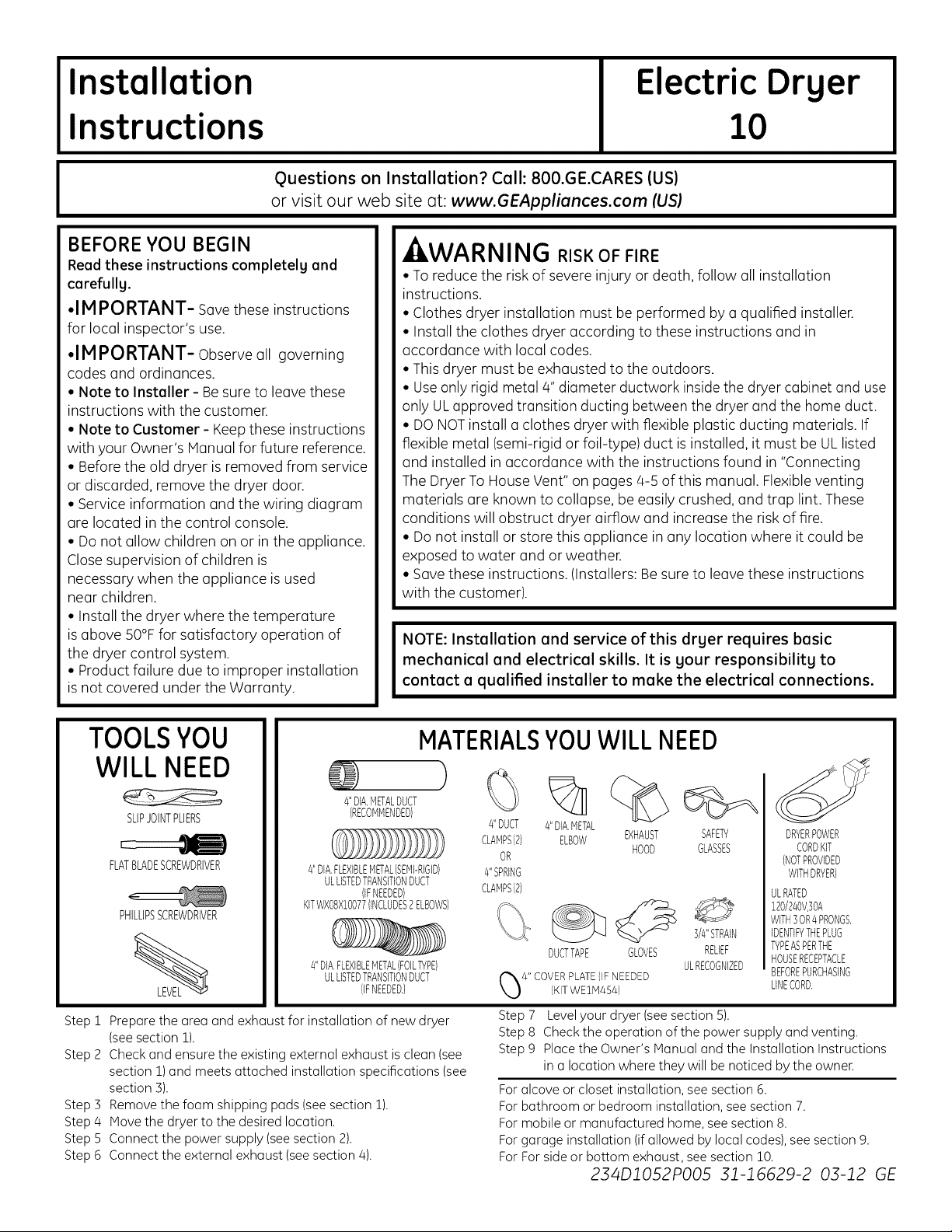
TOOLSYOU
WILL NEED
4"DIA.METALDUCT
SLIPJOINTPLIERS
FLATBLADESCREWDRIVER
PHILLIPSSCREWDRIVER
Prepare the area and exhaust for installation of new dryer
Step 1
(seesection 1).
Step 2
Check and ensure the existing external exhaust isclean (see
section 1)and meets attached installation specifications (see
section 3).
Remove the foam shipping pads (see section 1).
Step 3
Step 4
Move the dryer to the desired location.
Step 5
Connect the power supply (seesection 2).
Connect the external exhaust (seesection 4).
Step 6
(RECOMMENDED)
4"DIA,FLEXIBLEMETAL(SEMI-RIGID)
ULLISTEDTRANSITIONDUCT
KITWXB8XIBO77(INCLUDES2ELBOWSI
4"DIA.FLEXIBLEMETAL(FOILTYPEI
(IFNEEDED)
ULLISTEDTRANSITIONDUCT
(IFNEEDED,)
MATERIALSYOUWILL NEED
%
#'DUCT
CLAMPS(2) EXHAUST
4"SPRING
CLAMPS(2)
4"DIA.METAL
ELBOW
OR
DUCTTAPE GLOVES
4" COVERPLATE{IFNEEDED
{KITWE1M454)
Step7 Levelyour dryer (seesection5).
Step8 Checkthe operationofthe power supplyandventing.
Step9 PlacetheOwner'sManualandthe InstallationInstructions
in a locationwheretheywill benoticedbythe owner.
Foralcoveor closetinstallation,seesection6.
Forbathroom or bedroominstallation,seesection7.
Formobileor manufacturedhome,seesection8.
Forgarageinstallation(ifallowed by localcodes),seesection9.
ForForsideor bottom exhaust,seesection10.
HOOD
234DlO52PO05 31-16629-2 03-12 GE
%
SAFETY
GLASSES
3/4"STRAIN
RELIEF
ULRECOGNIZED
DRYERPOWER
CORDKIT
(NOTPROVIDED
WITHDRYER)
ULRATED
120/240V,]OA
WITH3OR4PRONGS,
IDENTIFYTHEPLUG
TYPEASPERTHE
HOUSERECEPTACLE
BEFOREPURCHASING
LINECORD,
Page 2

Installation Instructions
Minimum Clearance Other Than Alcove or Closet Installation
Minimum clearance to combustible surfaces and for air opening are: 0 in.clearance both sides, ] in. front and 3 in. rear.
Consideration must be given to provide adequate clearance for installation and service.
[] PREPARING FOR INSTALLATION
OF NEW DRYER
TIP:Install your dryer before installing your washer.
This will allow better accesswhen installing dryer exhaust.
REMOVING LINT FROM WALL EXHAUST
OPENING
• Remove and discard existing plastic or metal foil
transition duct and replace with UL listed transition duct.
WALL
INTERNALDUCT
OPENING OPENS
CHECKTHATEXHAUST
ANDCLOSESFREELY.
TILTTHE DRYER SIDEWAYS
AND REMOVE THE FOAM
SHIPPING PADS BY
PULLING AT THE SIDES
AND BREAKING THEM
AWAY FROM THE DRYER
LEGS.BE SURE TO
REMOVE ALL OF THE
FOAM PIECES AROUND
THE LEGS.
121ELECTRICAL CONNECTION INFORMATION
- kWARNING - TO REDUCE THE RISK OF
FIRE, ELECTRICAL SHOCK AND PERSONAL INJURY:
• DO NOT USE AN EXTENSION CORD OR AN
ADAPTER PLUG WITH THIS APPLIANCE.
Dryer must be electrically grounded in accordance with
local codes and ordinances, or in the absence of local
codes, in accordance with the NATIONALELECTRICAL
CODE,ANSI/NFPANO. 70.
ELECTRICAL REQUIREMENTS
This dryer must be connected to an individual branch
circuit, protected by the required time-delay fuses or
circuit breakers. A four or three-wire, single phase,
]20/240V or ]20/208V, 60Hz, 30 amp circuit is required.
GROUNDING INSTRUCTIONS
This dryer must be connected to a grounded metal, perma-
nent wiring system, or an equipment-grounding conductor
must be run with the circuit conductors and connected to
the equipment grounding terminal on the appliance.
CONNECTING DRYER USING 4-WIRE
CONNECTION (MUST BE USED FOR
MOBILE HONE INSTALLATION)
NOTE: Since January 1,1996, the National Electric code requires
that the new constructions utilize a 4-wire connection to an
electric drger.
REMOVEGROUNDSTRAP --
ANDDISCARD.KEEPGREEN HOT
GROUNDSCREW
_SCREWS
COVER
].Turn off the circuit breaker(s) (30 amp) or remove the
dryer's circuit fuse at the electrical box.
2.Be sure the dryer cord is unplugged from the wall
receptacle.
3. Remove the power cord cover located at the lower
back.
4. Remove and discard ground strap. Keep the green
ground screw for step 7.
5.Install 3/4 in. UL recognized strain relief to power cord
entry hole. Bring power cord through strain relief.
6.Connect power cord as follows:
A.Connect the 2 hot lines to the outer screws of
the terminal block (marked L] and L2).
B.Connect the neutral (white) line to the center of
the terminal block (marked N).
7.Attach ground wire of power cord with the green
ground screw (hole above strain relief bracket). Tighten
all terminal block screws (3)securely.
8. Properly secure power cord to strain relief.
9. Reinstall the cover.
A, i I^ ,-, ,, , , ,, , ,-
,I:IiW/'AKI_III_I_: NEVER LEAVE THE
COVER OFF OF THE TERMINAL BLOCK.
WIRE RELOCATEGREEN
GROUNDSCREW
HERE
3/4",UL
HOT RECOGNIZED
WIRE STRAINRELIEF
/4#10AWG MINIMUMCOPPER
CONDUCTORSOR]20/240V30APOWER
SUPPLYCORDKITMARKEDFORUSE
WITHDRYERS&PROVIDEDWITH
CLOSEDLOOPORSPADETERMINALS
WITHUPTURNEDENDS(NOTSUPPLIED}
GREENOR
Page 3
Installation Instructions
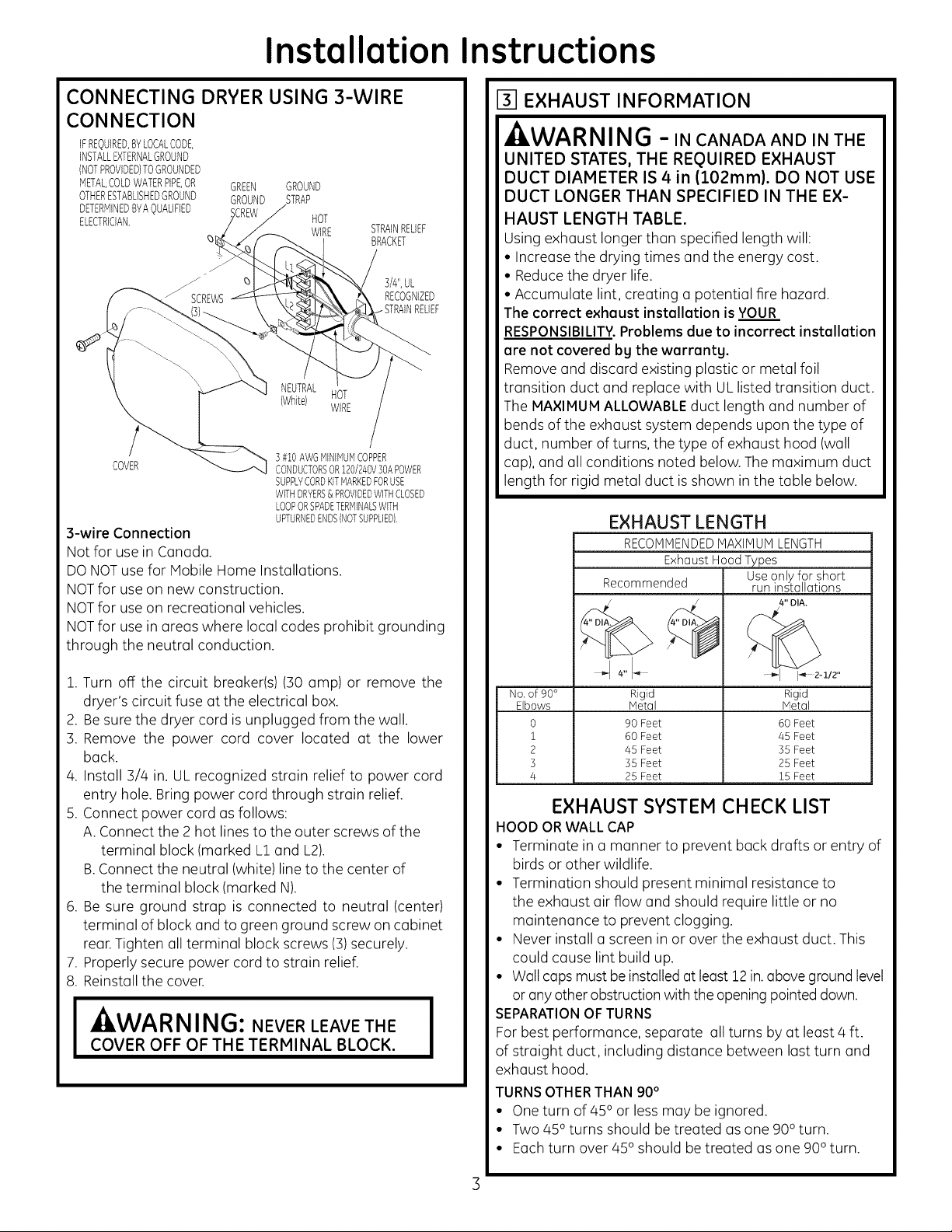
CONNECTING DRYER USING 3-WIRE
CONNECTION
IFREQUIRED,BYLOCALCODE,
INSTALLEXTERNALGROUND
(NOTPROVIDED)TOGROUNDED
METALCOLDWATERPIPE,OR GREEN GROUND
OTHERESTABLISHEDGROUND GROUND STRAP
DETERMINEDBYAQUALIFIED SCREW
ELECTRICIAN. HOT
COVER CONDUCTORSOR120/240V30APOWER
s-wire Connection
Not for use in Canada.
DONOTuse for Mobile Home Installations.
NOTfor use on new construction.
NOTfor use on recreational vehicles.
NOTfor use in areas where local codes prohibit grounding
through the neutral conduction.
WIRE STRAINRELIEF
NEUTRAL
(White) HOT
] #10AWGMINIMUMCOPPER
SUPPLYCORDKITMARKEDFORUSE
WITHDRYERS& PROVIDEDWITHCLOSED
LOOPORSPADETERMINALSWITH
UPTURNEDENDS(NOTSUPPLIED).
BRACKET
3/4",UL
RECOGNIZED
WIRE
[] EXHAUST INFORMATION
,AWARNING -INCANADAANDINTHE
UNITED STATES, THE REQUIRED EXHAUST
DUCT DIAMETER IS 4in (102ram). DO NOT USE
DUCT LONGER THAN SPECIFIED IN THE EX-
HAUST LENGTH TABLE.
Using exhaust longer than specified length will:
• Increase the drying times and the energy cost.
• Reducethe dryer life.
• Accumulate lint, creating a potential fire hazard.
The correct exhoust instollotion is YOUR
RESPONSIBILITY.Problems due to incorrect instollotion
ore not covered by the werronty.
Remove and discard existing plastic or metal foil
transition duct and replace with ULlisted transition duct.
The MAXIMUM ALLOWABLEduct length and number of
bends of the exhaust system depends upon the type of
duct, number of turns, the type of exhaust hood (wall
cap), and all conditions noted below. The maximum duct
length for rigid metal duct isshown in the table below.
EXHAUST LENGTH
RECOMMENDEDMAXIHUI LENGTH
ExhaustHoodTypes
Recommended runinstallations
Useonly forshort
4" DIA.
1. Turn off the circuit breaker(s) (30 amp) or remove the
dryer's circuit fuse at the electrical box.
2. Besure the dryer cord is unplugged from the wall.
3. Remove the power cord cover located at the lower
back.
4. Install 3/4 in. UL recognized strain relief to power cord
entry hole. Bring power cord through strain relief.
5. Connect power cord as follows:
A. Connect the 2 hot lines to the outer screws of the
terminal block (marked L1 and L2).
B.Connect the neutral (white) line to the center of
the terminal block (marked N).
6. Be sure ground strap is connected to neutral (center)
terminal of block and to green ground screw on cabinet
rear.Tighten all terminal block screws (3)securely.
7. Properly secure power cord to strain relief.
8. Reinstall the cover.
I WARNING: NEVER LEAVE THE I
COVER OFF OF THE TERMINAL BLOCK.
No, of 90°
Elbows
0
1
2
3
4
Rigid Rigid
Metal Metal
90 Feet 60 Feet
60 Feet 45 Feet
45 Feet 35 Feet
35 Feet 25 Feet
25 Feet 15 Feet
EXHAUST SYSTEM CHECK LIST
HOOD OR WALL CAP
• Terminate in a manner to prevent back drafts or entry of
birds or other wildlife.
• Termination should present minimal resistance to
the exhaust air flow and should require little or no
maintenance to prevent clogging.
• Never install a screen in or over the exhaust duct. This
could cause lint build up.
• Wall caps must be installed at least 12 in.aboveground level
or anyother obstruction with the openingpointed down.
SEPARATIONOFTURNS
For best performance, separate all turns by at least 4 ft.
of straight duct, including distance between last turn and
exhaust hood.
TURNSOTHERTHAN 90°
• Oneturn of 45oor less may be ignored.
• Two 450 turns should be treated as one 900turn.
• Each turn over 450should betreated as one 900 turn.
Page 4
Installation
nstructions
SEALING OFJOINTS
• Alljoints should be tight to avoid leaks.The male end of
each section of duct must point away from the dryer.
• The duct shall not be assembled with screws or other
fastening means that extend into the duct and catch lint.
• Duct joints can be made air and moisture-tight by
wrapping the overlapped joints with duct tape.
• Horizontal runs should slope down toward the outdoors
1/4 inch per foot.
INSULATION
Duct work that runs through an unheated area or is
near air conditioning should be insulated to reduce
condensation and lint build-up.
[] EXHAUST CONNECTION
- WARNING - TO REDUCE THE RISK
OF FIRE OR PERSONAL INJURY:
•This clothes dryer must be exhausted to the outdoors.
• Use only 4" rigid metal ducting for the home exhaust
duct.
• Use only 4" rigid metal or UL-listed flexible metal
(semi-rigid or foil-type) duct to connect the dryer to the
home exhaust duct. It must be installed in accordance
with the instructions found in"Connecting the Dryer to
House Vent" on pages 4-5 of this manual.
• Do not terminate exhaust in a chimney, a wall, a
ceiling, gas vent, crawl space, attic, under an enclosed
floor, or in any other concealed space of a building. The
accumulated lint could create a potential fire hazard.
• Never terminate the exhaust into a common duct with
a kitchen exhaust system. A combination of grease
and lint creates a potential fire hazard.
• Do not use duct longer than specified in the exhaust
length table. Longer ducts can accumulate lint,
creating a potential fire hazard.
• Never install a screen in or over the exhaust duct. This
will cause lint to accumulate, creating a potential fire
hazard.
• Do not assemble ductwork with any fasteners that
extend into the duct. These fasteners can accumulate
lint, creating a potential fire hazard.
• Do not obstruct incoming or exhausted air.
• Provide an access for inspection and cleaning of the
exhaust system, especially at turns and joints. Exhaust
system shall be inspected and cleaned at least once a
year.
There are multiple installation options.
Select the most appropriate method for
your installation situation.
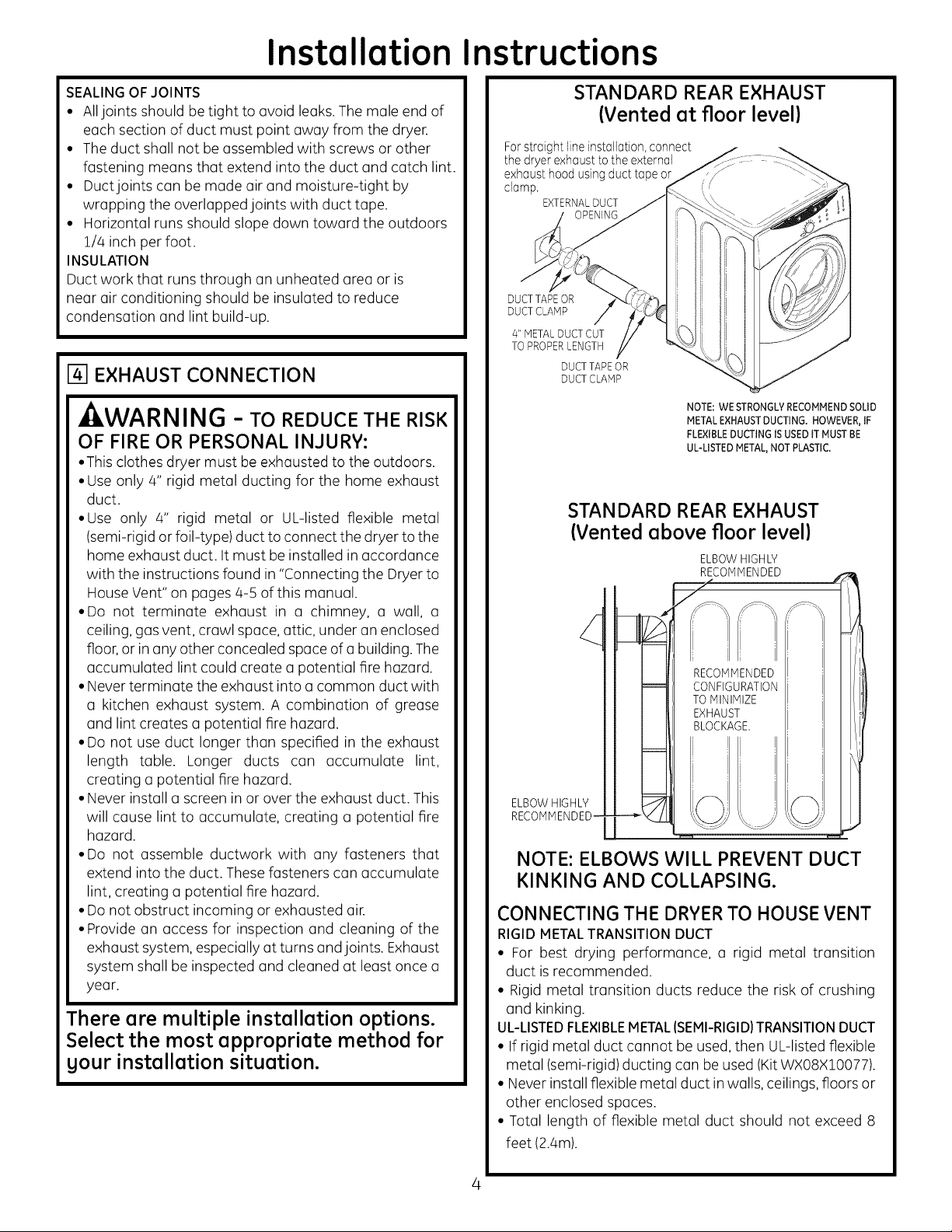
STANDARD REAR EXHAUST
(Vented at floor level)
For straight line installation, connect
the dryer exhaust to the external
exhaust hood using duct tape or
clamp.
EXTERNALDUCT
DUCT TAPEOR
DUCT CLAMP
4" METALDUCT CUT
TO PROPERLENGTH
DUCTTAPE OR
DUCTCLAMP
NOTE: WE STRONGLYRECOMMENDSOLID
METALEXHAUSTDUCTING. HOWEVER,IF
FLEXIBLEDUCTING ISUSEDtT MUST BE
UL-LISTED METAL,NOT PLASTIC.
STANDARD REAR EXHAUST
(Vented above floor level)
ELBOWHIGHLY
d
: i
C()[I-FIGUFATI_D-N I '
TOMINIMIZE I !
EXHAUST
BL J I :IOCKAGE I i
ELBOWHIGHLY
RECOMMENDED-
!
NOTE: ELBOWS WILL PREVENT DUCT
KINKING AND COLLAPSING.
CONNECTING THE DRYERTO HOUSE VENT
RIGID METALTRANSITION DUCT
• For best drying performance, a rigid metal transition
duct isrecommended.
• Rigid metal transition ducts reduce the risk of crushing
and kinking.
UL-LISTEDFLEXIBLEMETAL(SEMI-RIGID)TRANSITIONDUCT
• If rigid metal duct cannot be used, then UL-listed flexible
metal (semi-rigid) ducting can beused (KitWXO8XlO077).
• Neverinstall flexible metal duct in walls, ceilings, floors or
other enclosed spaces.
• Total length of flexible metal duct should not exceed 8
feet (2.4m).
Page 5
Installation Instructions
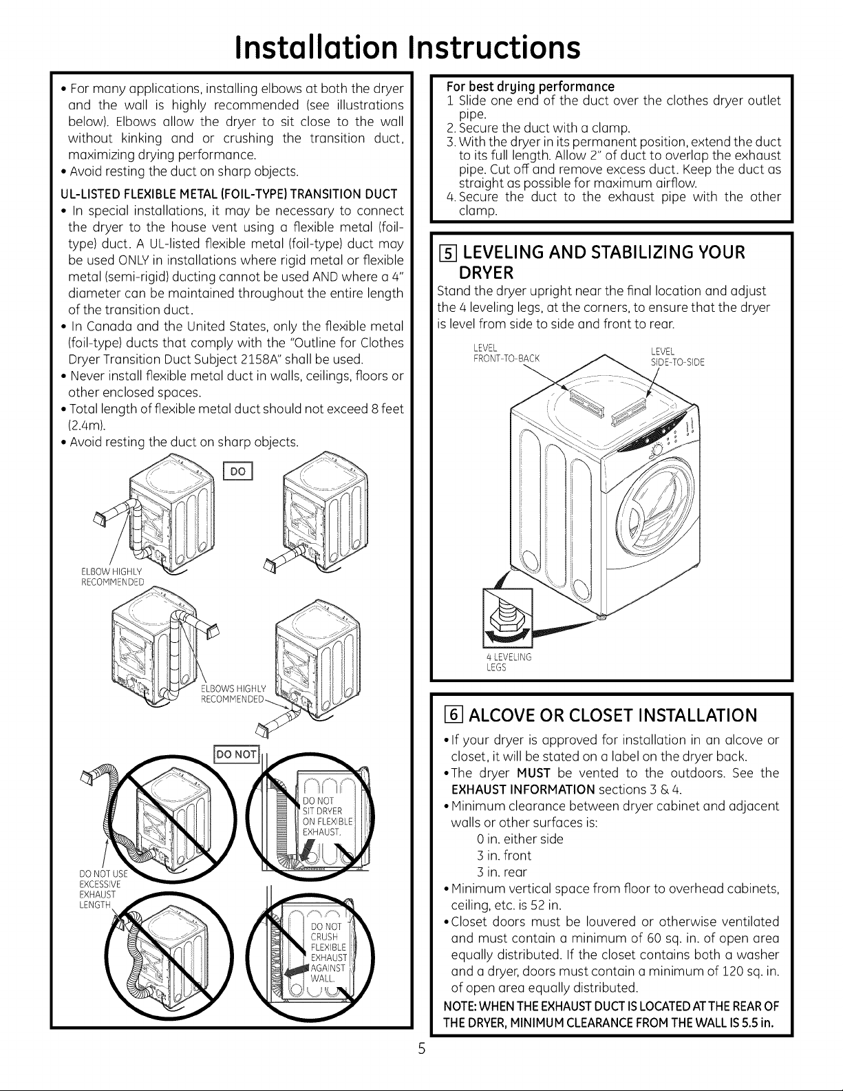
• For many applications, installing elbows at both the dryer
and the wall is highly recommended (see illustrations
below). Elbows allow the dryer to sit close to the wall
without kinking and or crushing the transition duct,
maximizing drying performance.
• Avoid resting the duct on sharp objects.
UL-LISTEDFLEXIBLEMETAL{FOIL-TYPE)TRANSITIONDUCT
• In special installations, it may be necessary to connect
the dryer to the house vent using a flexible metal (foil-
type) duct. A UL-listed flexible metal (foil-type) duct may
be used ONLYin installations where rigid metal or flexible
metal (semi-rigid) ducting cannot be used ANDwhere a4"
diameter can be maintained throughout the entire length
of the transition duct.
• In Canada and the United States, only the flexible metal
(foil-type) ducts that comply with the "Outline for Clothes
Dryer Transition Duct Subject 2158A" shall be used.
• Never install flexible metal duct in walls, ceilings, floors or
other enclosed spaces.
• Total length of flexible metal duct should not exceed 8feet
(2.4m).
• Avoid resting the duct on sharp objects.
For best drying performance
1 Slide one end of the duct over the clothes dryer outlet
pipe.
2.Secure the duct with mclamp.
3.With the dryer in its permanent position, extend the duct
to its full length. Allow 2" of duct to overlap the exhaust
pipe. Cut off and remove excess duct. Keep the duct as
straight as possible for maximum airflow.
4.Secure the duct to the exhaust pipe with the other
clamp.
[] LEVELING AND STABILIZING YOUR
DRYER
Stand the dryer upright near the final location and adjust
the 4 leveling legs, at the corners, to ensure that the dryer
islevel from side to side and front to rear.
LEVEL LEVEL
FRONTTO BACK SIDE-TO SIDE
ELBOWHIGHLY
RECOk_,MENDED
EXHAUST
LENGTH
(
4 LEVELING
LEGS
[] ALCOVE OR CLOSET INSTALLATION
• If your dryer is approved for installation in an alcove or
closet, it will be stated on a label on the dryer back.
•The dryer MUST be vented to the outdoors. See the
EXHAUSTINFORMATIONsections 3 & 4.
• Minimum clearance between dryer cabinet and adjacent
walls or other surfaces is:
0 in. either side
3 in.front
3 in.rear
• Minimum vertical space from floor to overhead cabinets,
ceiling, etc. is 52 in.
•Closet doors must be Iouvered or otherwise ventilated
and must contain o minimum of 60 sq. in. of open area
equally distributed. If the closet contains both o washer
and a dryer, doors must contain o minimum of 120 sq. in.
of open area equally distributed.
NOTE:WHENTHEEXHAUSTDUCTISLOCATEDATTHEREAROF
THEDRYER,MINIMUMCLEARANCEFROMTHEWALLIS5.5in.
Page 6

Installation Instructions
I-_ BATHROOM OR BEDROOM INSTALLATION
• The dryer MUST be vented to the outdoors. See EXHAUST
INFORMATION section :3& 4.
• The installation must conform with local codes or, in the
absence of local codes, with the NATIONAL ELECTRICAL
CODE, ANSI/NFPA NO. 70.
F-_MOBILE OR MANUFACTURED HOME
INSTALLATION
•Installation must conform to the MANUFACTURED HOME
CONSTRUCTION & SAFETY STANDARD, TITLE 24, PART
:32-80 or, when such standard is not applicable, with
AMERICAN NATIONAL STANDARD FOR MOBILE HOME,
ANSI/NFPA NO. 501B.
• The dryer MUST be vented to the outdoors with the
termination securely fastened to the mobile home
structure. (See EXHAUST INFORMATION section :3 & 4).
• The vent MUST NOT be terminated beneath a mobile or
manufactured home.
• The vent duct material MUST BE METAL.
• Do not use sheet metal screws or other fastening devices
which extend into the interior of the exhaust vent.
• See section 2 for electrical connection information.
FIXINGHOLE
B A
.
Cut the duct as shown and keep portion A.
TAB LOCATION
BENDTAB
UP45o
Through the rear opening, locate the tab in the middle of
the appliance base. Lift the tab to about 450 using a flat
blade screwdriver.
19IGARAGE INSTALLATION (IF ALLOWED
BY LOCAL CODES)
• Dryers installed in garages must be elevated 18 inches
(46cm) above the floor.
I1-O1DRYEREXHAUST TO RIGHT, LEFT OR
BOTTOM CABINET
, WARNING - BEFOREPERFORMING
THIS EXHAUST INSTALLATION, BESURE
TO DISCONNECT THE DRYER FROM ITS
ELECTRICAL SUPPLY.PROTECT YOUR
HANDS AND ARMS FROM SHARP EDGES
WHEN WORKING INSIDE THE CABINET.
BESURE TO WEAR GLOVES.
REMOVE
SCREW
ANDSAVE.
ADDING NEW DUCT
FIXING
HOLE
PORTION"A"
RIGHTOR
LEFTSIDE
EXHAUST
Reconnect the cut portion (A)of the duct to the blower
housing. Make sure that the shortened duct is aligned with
the tab in the base. Use the screw saved previouslg to secure
the duct in place throuqh the tab on the appliance base.
REMOVEDESIRED
KNOCKOUT(ONEONLY).
Detach and remove the bottom, right or left side knockout
as desired. Remove the screw inside the dryer exhaust duct
and save. Pull the duct out of the dryer.
Page 7

Installation Instructions
ADDING ELBOW AND DUCT FOR
EXHAUST TO LEFT OR RIGHT SIDE OF
CABINET
• Preassemble 4" elbow with 4" duct. Wrap duct tape
Ground joint.
• Insert duct assembly, elbow first, through the side
opening and connect the elbow to the dryer internal
duct.
-&CAUTION: Be sure not to pullor damage the
electrical wires inside the drger when inserting the duct.
EXHAUSTCAN
BEADDEDTO
LEFTORRIGHTSIDE
ADDING COVER PLATE TO REAR OF
CABINET (SIDES AND BOTTOM EXHAUST)
PLATE
{KITWE1M454)
Connect standard metal elbows and ducts to complete
the exhaust system. Cover back opening with a plate (Kit
WEllV]454) available from your local service provider. Place
dryer in final location.
-_WARNING-NEVER LEAVE THE
BACK OPENING WITHOUT THE PLATE
(Kit WEIM454).
• Apply duct tape as shown on the joint between the
dryer internal duct and the elbow.
DUCT CAUTION:
Internal duct joints must be
secured with tape, otherwise
theg mag separate and cause a
safetg hazard.
ADDING ELBOW FOR EXHAUST
THROUGH BOTTOM OF CABINET
• Insert the elbow through the rear opening and connect
it to the dryer internal duct.
•Apply duct tope on the joint between the dryer internal
duct and elbow, as shown above.
REGISTER YOUR NEW APPLIANCE TO RECEIVE ANY
IMPORTANT PRODUCT NOTIFICATIONS.
Please go to www.GEAppliances.com or mail in
your product registration curd.
For questions on installation, coil: 800.626.2000 (US) or
800-561-3344 (Canada).
CAUTION:
Internal duct joints must be secured with tape,
otherwise they may separate and cause a
safety hazard.
Page 8

Page 9

Instrucciones
Secadora El ctrica
de instalaci6n
2,Preguntas sabre la instalaci6n? Llame al: 1-800-GECARES (EE.UU.)
o visite nuestro sitio Web en: www.GEAppliances.corn (EE.UU.)
ANTES DE COMENZAR
Lea estas instrucciones par completo y con
detenimiento.
•IM PORTANTE - Guarde estas instruc-
ciones para el usa de inspectores locales.
•IMPORTANTE - Siga todos los c6digos
y ordenanzas vigentes.
• Nota al instalador - AsegOrese de dejar
estas instrucciones con el consumidor.
• Nota al consumidor - Mantenga estas
instrucciones con el Manual del propietario
para referencia futura.
• Antes de que la secadora antigua sea retirada
del servicio o eliminada, quftele la puerta.
• Lainformaci6n sabre reparaciones y el
diagrama del cableado se encuentran en la
consola de control.
• No permita que niflos sesuban o se metan
dentro del aparato. Se requiere una super-
visi6n estricta cuando el aparato es utilizado
cerca de nifios.
• Instale la secadora en lugares donde la
temperatura sea mayor a 50°F para un
funcionamiento satisfactorio del sistema de
control de la secadora.
• Lagarant[a no cubre las fallas del producto
debido a una instalaci6n incorrecta.
10
I
- ADVERTENCIA RIESGO DE INCENDIO
• Para reducir el riesgo de una lesi6n grave o de muerte, cumpla con
todas las instrucciones de instalaci6n.
• Lainstalaci6n de la secadora debe efectuarla un instalador calificado.
• Instale la secadora de ropa de acuerdo con estas instrucciones yen
cumplimiento de los c6digos locales.
• Estasecadora debe tener una salida al exterior.
• Utilice s61oun conducto r[gido de metal de un di6metro de 4" dentro del
gabinete de la secadora y use s61oun conducto detransici6n aprobado
par ULentre la secadora y el conducto dom#stico.
• NOinstale una secadora de ropa con conductos de pl6stico flexibles.
Si se instala un conducto flexible de metal (semi r[gido o de tipo papel de
aluminio), debe estar aprobado par ULe instalarse de acuerdo con las
instrucciones de "C6mo conectar la secadora a la ventilaci6n dom#stica"
de las p6ginas 4-5 de este manual. Los materiales de ventilaci6n
flexibles a menudo se desploman, se aplastan y atrapan pelusas. Estas
condiciones obstruyen la corriente de aire de la secadora e incrementan
el riesgo de incendio.
• No instale o almacene este aparato en un lugar donde se vea expuesto
al agua y/o alas inclemencias del tiempo.
• Guarde estas instrucciones. (Instaladores: AsegOrese de dejar estas
instrucciones al consumidor).
NOTA:La instalaci6n g reparaci6n de esta secadora requieren capaci-
dades mec6nicas y el_ctricas b6sicas. Essu responsabilidad contactar
a un instalador calificado para realizar las conexionesel_ctricas.
HERRAMIENTAS
NECESARIAS
CONDUCTODEMETALDE#' DEDIA
AUCATESDEJUNTADESLIZANTE
DESTORNILLADORPLANO
DESTORNILLADORDEESTRELLA
Paso 1
Prepareel6reay lasalidaparalainstalaci6nde lanueva
secadora (ver secci6n 1).
Paso 2
Verifique y asegOrese de que lasalida al exterior existente
est# limpia (ver secci6n 1)y que cumpla con las especifi-
caciones de instalaci6n incluidas (versecci6n 3).
Paso 3
Quite las almohadittas de espuma para envio (ver secci6n 1).
Paso Q
Desplace la secadora a la ubicaci6n deseada.
Paso 5
Conecte el suministro de energfa (ver secci6n 2).
Paso 6
Conecte la salida al exterior (ver secci6n 4).
Paso 7
Nivele su secadora (versecci6n 5).
Paso 8
Verifique el funcionamiento del suministro de energfa y
(RECOMENDADO)
CONDUCTODETR#NSIOONDEMET&L
FLEXIBLE(SEMIRIGIDO/DE4"DEDIA, DERESORTEDE4"(2)
APROBADOPORUL(SIFUERANECESARIO}
KITWXO8XIOO77(INCLUYE2CODOSI _ _ AUVIODETENSION
CONDUCTODETRANSIOONDEMETAL
FLEXIBLE(TIPOPAPELDEALUMINIO}DE4"DEDI#.
APROBADOPORUL(SIFUERANECESARIOI a "PLACADECUBIERTA
HATERIALES
)
ABRAZADERAS
DECONDUCTODE4"(2)
0
ABRAZADERAS
ONTAADHESIVA PORUL
de la ventilaci6n.
Paso 9 Coloque el manual del propietario y las instrucciones de
instalaci6n en un lugar de fcicil acceso para el propietario.
Para instalaci6n en nicho o closet, ver secci6n 6.
Para instalaci6n en baflos o dormitorios, ver secci6n 7.
Para casas m6viles o prefabricadas, ver secci6n 8.
Para instalaci6n en garaje (sipermitido por loscodigos locales),ver
secci6n 9.
Para salidas laterales o por la parte inferior, ver secci6n 10.
NECESARIOS
KITDECABLE
CODODEMETAL
DE4"DEDIA. CAMPANA GAFAS
DESALIDADESEGURIDAD
GUANTES DE3A"RECONOODO
LJ
234DlO52PO05 31-16629-2 03-12 GE
DEENERGIA
DELASECADORA
(NOPROVBTACON
LASECADORAI
CAPACIDAD UL DE
220/240V30A
CON 3 0 4 PUNTAS
ANTES DE COMPRAR EL
CORDON IDENTIFIQUE
EL TIPO DE ENCHUFE DE
ACUERDO CON EL
RECEPTACULO
DE LA CASA
Page 10

Instrucciones de instalaci6n
Espaciominimo diferente a instalaci6n en nichos oclosets
Losespacioslibresm[nimosrespectodesuperficiescombustiblesy deaberturasde aireson:Espaciode0 pulg.aamboslados,1 pulg.enel
frentey 3 pulg.enlapartetrasera. Oebetenerseencuentaunespaciolibreadecuadoparaunfuncionamientoy reparaci6ncorrectos
m PREPARACION PARA LA INSTALACION
DE UNA SECADORA NUEVA
CONSEJO:Instale su secadora antes de instalar la lava-
dora. Esto permitir6 un mejor acceso cuando instale la
salida de la secadora.
COMO OUITAR PELUSA DE LA ABERTURA
DE LA SALIDA DE LA PARED
• Quite y descarte el conducto de transici6n existente de
pl6stico o de papel de aluminio y coloque un conducto
de transici6n aprobado por UL.
ABERTURA DE
VERIFIQUE QUE
EL REGULADOR
DE TIRO DE LA CAMPANA
DE SALIDA SEABRA
Y CIERRE UBREMENTE
INCLINE LA SECADORA
DECOSTADO Y QUITE
LAS ALMOHADILLAS
DE ESPUJqA PARA ENV[O
TOMANDOLAS DE LOS
COSTADOS Y
ARRANCANDOLAS DE LAS
PATASDE LA SECADORA.
ASEGORESE DE OUITAR
TODAS LAS PIEZAS
DE ESPUJqA UBICADAS
ALREDEDOR DE LAS PATAS.
121INFORMACION SOBRE CONE×IONES
ELECTRICAS
- ADVERTENCIA - PARA RE DUCIR EL
RIESGO DE INCENDIO, DESCARGA ELECTRICA
V LESIONES PERSONALES:
• NO UTILICE UN CABLE DE EXTENSI6N O UN
ENCHUFE ADAPTADOR CON ESTE APARATO.
La secadora debe contar con una conexi6n el6ctrica a
tierra en cumplimiento con los c6digos y ordenanzas
locales, o si 6stos no existieran, de acuerdo con el
CODIGOELE_CTRICONACIONAL,ANSI/NFPAN°. 70.
REOUISITOS ELI_CTRICOS
Esta secadora debe conectarse a un circuito derivado
individual, con la protecci6n de los fusibles de tiempo
retardado o interruptores de circuito requeridos. Se requiere
un circuito de tres o cuatro cables, fase Onica, 120/280V 6
120/208V, 60Hz y 30 amperios.
INSTRUCCIONES DE CONEXI6N A TIERRA
Esta secadora debe conectarse a un sistema de cableado
permanente con conexi6n a tierra o debe utilizarse un con-
ductor de conexi6n a tierra del equipamiento con los con-
ductores de circuito y conectarse a la terminal de conexi6n
a tierra del aparato.
COMO CONECTAR LA SECADORA USAN-
DO UNA CONE×I6N DE 4 CABLES (DEBE
UTILIZARSE EN INSTALACIONES DE CASAS
M6VILES)
NOTA:Desdeel I de enero de 1996,el C6digoEl_ctricoNacional
exige que las nuevasconstrucciones utilicen una conexi6n de 4
cables a una secadorael_ctrica.
QUITE LA CINTA DE
CON EXl6N A TIERRA
Y DESCARTELA CONSERVE
EL TORNILLO VERDE
DE CONEXl6N ATIERR/_
TAPA
VIVO
VUELVA A COLOCAR
ELTORNILLO VERDE
DE CONEXl6N ATIERRA AOUi
CABLEVERDE
DE AUVIO
BRACKET
ALIVIO DE TENSI6N
CABLE DE ¾" RECONOCIDO
VIVO POR UL
4 CONDUCTORES DE COBRE #10 AWG
NiNINO O KIT DE CABLE DE SUNINISTRO
DE ENERGiA DE 120/240V 30A NARCADO
PARA USO EN SECADORAS Y PROVISTO
CON TERNINALES DE BUCLE CERRADO O
DE PALA CON EXTRENOS NACIA ARRIBA
(NO PROVISTOS}
i. Desactive el interruptor de circuitos (30 amperios) o
quite el fusible del circuito de la secadora de la caja
el#ctrica.
2.Verifique que elcable dela secadora est# desenchufado
del tomacorriente.
3. Quite la tapa del cable de energia ubicada en la parte
trasera inferior.
4.Quite y descarte la cinta de conexi6n a tierra. Conserve
el tornillo verde de conexi6n a tierra para el paso 7.
5. Instale un alivio de tensi6n de sApulgadas reconocido
por UL en el orificio de entrada del cable de energia.
Paseel cable de energia a trav@sdel alivio de tensi6n.
6.Conecte el cable de energia de la siguiente manera:
A. Conecte los dos cables vivos a los tornillos externos
del bloque terminal (marcado L1y L2).
B.Conecte el cable neutral (blanco) al centro del bloque
terminal (marcado N).
7. Conecte el cable a tierra del cable de energia con el
tornillo verde de conexi6n a tierra (orificio sobre el
soporte de alivio de tensi6n). Ajuste por firmemente
todos los tornillos (3)del bloque terminal.
8.Ajuste bien el cable de energia al alivio de tensi6n.
9.Vuelva a instalar la tapa.
- ADVERTENCIA: NUNCA OL-
VIDE DE VOWER A COLOCAR LA TAPA DEL
BLOQUE TERMINAL.
Page 11

Instrucciones de instalaci6n
C6MO CONECTAR LA SECADORA UTILI-
ZANDO UNA CONE×I6N DE 3 CABLES
SI ASi LO REOUIRIERAN LOS CODIGOS TORNILLO CINTA DE CONEXION
LOCALES, INSTALL UNA CONEXION VERDE
A TIERRA EXTERNA (NO PROVISTA) DE CONEXION /A
A METAL CON CONEXION A TIERRA, A TIERRA /
TUBERiAS DE AGUA FRiA CON CONEXION /
A TIERRA U OTRA CONEXION A TIERRA _ CABLE VWO
ESTABLECIDA PaR UN ELECTRICISTA
CAURCADO
/
TAPA
TIERRA
SOPORTE
DE ALIVIO
DE TENSION
ALWIO DE TENSION
DE %" RECONOQDO
PaR UL
MINIMa O KI] DE CABLE DE SUP11NISTRO
DE ENERG[A DE 120/2a0V }0A IV1ARCADO
DE PALA CON EXTREIV!OSHACIA ARRIBA
(NO PROVISTOS)
Conexi6n de 3 cables
NOusar en Canad6.
NOusar en instalaciones en casas m6viles.
NOusar en casas nuevas.
NOusar en vehiculos recreativos.
NO usar en 6reas donde los c6digos locales proh[ben
la connexi6n el6ctrica a tierra par el media del cable
neutral.
1. Desactive el interruptor de circuitos (30 amperios) o
quite el fusible del circuito de la secadora de la caja
el6ctrica.
2. Verifique que el cable de la secadora est6
desenchufado del tomacorriente.
3. Quite latapa del cable de energia ubicada en la parte
trasera inferior.
4. Instale un alivio de tensi6n de s4pulgadas reconocido
par ULen el orificio de entrada del cable de energia.
Paseel cable de energia a trav6s del alivio de tensi6n.
5.Conecte el cable de energia de la siguiente manera:
A. Conecte los dos cables vivos a los tornillos externos
del bloque terminal (marcado L1y L2).
B.Conecte el cable neutral (blanco) al centro del bloque
terminal (marcado N).
6. AsegOrese de que la cinta de conexi6n a tierra est6
conectada a la terminal neutral (central) del bloque
y al tornillo verde de conexi6n a tierra de la parte
trasera del gabinete. Ajuste par firmemente todos los
tornillos (3)del bloque terminal.
7.Ajuste bien el cable de energia al alivio de tensi6n.
8. Vuelva a instalar la tapa.
- ADVERTENCIA: NUNCA OL-
VIDE DE VOLVER A COLOCAR LA
TAPA DEL BLOQUE TERMINAL.
[] INFORMACION DE SALIDA
- ADVERTENCIA- EN CANAD/_ Y
LOS ESTADOS UNIDOS, EL DIAMETRO
DE CONDUCTO DE SALIDA REQUERIDO
ESDE 4 PULG. (102 mm). NO UTILICE UN
CONDUCTO DE UNA LONGITUD MAYOR
A LA ESPECIFICADA EN LA TABLA DE
LONGITUD DE SALIDA.
AIutilizar una salida de mayor Iongitud a la especificada se:
• Incrementardn lostiempos desecadoy el costa de energ[a.
• Reducir6 lavida 0til de la secadora.
• Acumular6 pelusa, Io que podria generar un riesgo
potencial de incendio.
La correcta instalaci6n de salida es SU
RESPONSABILIDAD. Los problemas generados por una
instalaci6n incorrecta no se encuentran cubiertos por
la garantia.
Quite y descarte el conducto detransici6n existente de
pl6stico o de papel de aluminio y coloque un conducto
de transici6n gprobado par UL.
La Iongitud MA×IMA PERMITIDAdel conducto y la
cantidad de codas del sistema de salida dependen
del tipo de conducto, la cantidad de curvas, laclase
de campana de salida (cubierta de pared) y todas las
condiciones indicadas acontinuaci6n. La Iongitud
m6xima del conducto para conductos r[gidos de metal
se indica en lasiguiente tabla.
LONGITUD DE SALIDA
LONGITUDIvI_,XIIV1ARECOMENDADA
Tipos de campana de salida
Recomendado
Cant. de
codas de 90°
0
1
2
3
Metal
Rigido
90 Pies
60 Pies
45 Pies
35 Pies
LISTADE CONTROL DEL SISTEMA DE SALIDA
CAMPANA 0 CUBIERTADEPARED
• Instale la salida de modo de evitar contracorrientes o el
ingreso de p6jaros u arras insectos o animales.
• La boca de salida debe presentar una resistencia
minima al flujo de salida y debe requerir poco o ningOn
mantenimiento para evitar las obstrucciones.
• Nunca instale un filtro dentro o sabre el conducto de
salida. Esto podrfa provocar una acumulaci6n de pelusa.
• Las cubiertas de pared deben instalarse par Io menos a
12" sabre el nivel del suelo o cualquier otra obstrucci6n
con la abertura apuntando hacia abajo.
SEPARACIONDECURVAS
Para un mejor desempeflo, separe todas las curvas con par
Io menos 4 pies de conducto recto, incluyendo la distancia
entre la Oltima curva y la campana de salida.
GIROSQUENO SON DE90•
• Un giro de 450 o menos puede ignorarse.
• Dos giros de 450deben tratarse coma ungiro de 90°.
• Todoslosgirosdemdsde450debentratarsecomaungirode90°.
Utilizar s61oen instaladones
de trayeeto corto
4" DIA.
I" z-tim+'
Metal
Rigido
60 Pies
45 Pies
35 Pies
25 Pies
Page 12

Instrucciones de instalaci6n
SELLADO DE JUNTAS
• Todas lasjuntas deben estar bien selladas para evitar p@didas.
Elextremo macho de cada secci6n de conducto debe apuntar
en direcci6n opuesta a la secadora.
• El conducto no debera instalarse con tornillos u otros medios de
sujeci6n que se extiendan dentro del conducto y enganchen
pelusas.
• Lasjuntas de los conductos deben ser herm@icas al aire y a
la humedad mediante la superposici6n de juntas con cinta
aislante.
• Los tramos horizontales deben tener una inclinaci6n hacia el
exterior de 1/4" por pie.
AISLACION
Los conductos instalados a trav_s de una cirea sin calefacci6n o
ubicados cerca de un acondicionador de aire deben aislarse para
reducir la condensaci6n y la acumulaci6n de pelusas.
CONE×I6N A LA SALIDA
ADVERTENCIA - PARA
REDUCIR EL RIESGO DE INCENDIO O
DE LESIONES PERSONALES:
• Esta secadora de ropa debe tener una salida al
exterior.
• Utilice s61oun conducto de metal rigido de 4" para el
conducto de salida dom6stico.
• Use s61o un conducto de metal rigido de 4"o de
metal flexible (semi rigido o de tipo papel de aluminio)
aprobado por UL para conectar la secadora al
conducto de salida dom6stico. Debe instalarse de
acuerdo con las instrucciones incluidas en "C6mo
conectar la secadora a la ventilaci6n dom6stica" de
las p6ginas 4-5 de este manual.
• No instale la boca de salida dentro de una chimenea,
pared, cielorraso, ventilaci6n de gas, espacio entre
pisos, 6tico, bajo un piso con cerramiento o en
cualquier otro espacio oculto de un edificio. La
acumulaci6n de pelusas podria provocar un riesgo
potencial de incendio.
• Nunca instale la boca de salida dentro de un conducto
com0n con el sistema de salida de la cocina. La
combinaci6n de grasa y pelusas podria provocar un
riesgo potencial de incendio.
• No utilice un conducto de una Iongitud mayor a la
especificada en la tabla de Iongitud de salida. Los
conductos m6s largos acumulan pelusa, Io que
genera un riesgo potencial de incendio.
• Nunca instale un filtro dentro o sobre el conducto de
salida. Esto provocar6 la acumulaci6n de pelusas, Io
que genera un riesgo potencial de incendio.
• No arme la red de conductos con sujeciones que
se extiendan dentro del conducto. Estas sujeciones
pueden acumular pelusa, Io que genera un riesgo
potencial de incendio.
• No obstruya el aire que entra y sale.
• Incluya un acceso para inspecci6n y limpieza del
sistema de salida, especialmente en las curvas y
juntas. El sistema de salida debe inspeccionarse y
limpiarse por Io menos una vez al aBo.
Existen opciones m61tiples de instalaci6n.
Seleccione el m_todo m6s apropiado para su
instalaci6n.
SALIDA TRASERA EST#,NDAR
(Ventilaci6n a nivel del suelo)
Para una instalad6n en linea recta, conecte
lasalidade la secadoraa la campana
desalidaal exteriorcondnta aislante
o una abrazadera
ABERTURA DE
CONDUCTO EXTERIOR
CINTA AISLANTE
O
DE CONDUCTO
CONDUCTO DE METAL
DE 4" CORTADO
CON LA LONGITUD ADECUADA
CINTA AISLANTE O
ABRAZADERA DE CONDUCTO
NOTA: RECOMENDAMOS ENFATICAMENTE EL USO
DECONDUCTOS DE SALIDA DE METAL SOLIDO.
SIN EMBARGO, SI SE USAN CONDUCTOS FLEXIBLES
ESTOSDEBEN SER DE METAL APROBADOS PORU[
NO DE PLASTICO.
SALIDA TRASERA ESTANDAR
(Ventilaci6n sobre el nivel del suelo)
SERECOMIENDA
ELUSO DECODOS-
NOTA: LOS CODOS EVITAN QUE LOS
CONDUCTOS SE DOBLEN O CAIGAN.
C6MO CONECTAR LA SECADORA A LA VEN-
TILACION DOMESTICA
CONDUCTODE TRANSlCION DE METALRIGIDO
• Para un mejor desempe_o de secado, se recomienda un
conducto de transici6n de metal rigido.
• Los conductos de transici6n de metal rigidos reducen el
riesgo de aplastamientos g torceduras.
CONDUCTODETRANSICIONDEMETALFLEXIBLE
(SEMI-RiGIDO)APROBADOPOR UL
• Si no puede utilizarse un conducto de metal r[gido, entonc-
es puede usarse un conducto de metal flexible (semi-r[gido)
aprobado por UL(KitWX08X10077).
• Nunca instale conductos de metal flexibles en paredes,
cielorrasos, pisos u otros espacios cerrados.
• La Iongitud total del conducto de metal flexible no deber6
superar los 8 pies (2./4m).
Page 13

Instrucciones de instalaci6n
• Para muchas aplicaciones, se recomienda enf6ticamente
la instalaci6n de codos en la secadora y en la pared
(ver ilustraciones de abajo). Los codos permiten que la
secadora se ubique cerca de la pared sintorcer o aplastar
el conducto de transici6n, Io que potencia al mOximo el
desempeflo de secado.
• No coloque el conducto sobre objetos afilados.
CONDUCTO DE TRANSICION DE METAL FLEXIBLE(SEMI-
RiGIDO)APROBADOPORUL
• Eninstalaciones especiales,puede sernecesario conectar la
secadora a la ventilaci6n dom@sticautilizando un conducto
de metal flexible (tipo papel de aluminio). Puede utilizarse
un conducto de metal flexible (tipo papel de aluminio)
aprobado por UL SOLO en instalaciones en las que no
pueden usarse conductos de metal rfgidos o flexibles (semi-
rigidos)Yen lasque puede mantenerse un didmetro de 4" a
Iolargo de todo el conducto de transici6n.
• En Canad6 y los Estados Unidos, solamente deberOn
utilizarse los conductos de metal flexibles (tipo papel de
aluminio) que cumplan con el "Resumen para conductos
de transici6n para secadoras de ropa, Tema 2158A".
• Nunca instale conductos de metal flexibles en paredes,
cielorrasos, pisos u otros espacios cerrados.
• La Iongitud total del conducto de metal flexible no deber6
superar los 8 pies (2.4m).
• No coloque el conducto sobre objetos afilados.
Poro un mejor desempe_o de secodo:
1.Deslice un extremo del conducto sobre latuberia de salida
de la secadora de ropa.
2.Fijeel conducto con una abrazadera.
3. Con la secadora en su posici6n permanente, extienda el
conducto en su Iongitud total. Dejeque se superpongan 2"
de conducto con la tuberia de salida. Corte y quite el tramo
de conducto que sobre. Mantenga el conducto Iom6s recto
posible para Iograr una corriente de aire m6xima.
4. Fijeel conducto a la tuberia de salida con la otra abraza-
dera.
E C6MO NIVELAR Y ESTABILIZAR SU
SECADORA
Coloque la secadora en posici6n vertical cerca de la
ubicaci6n definitiva y ajuste las cuatro patas de nivelaci6n,
en los extremos, para garantizar que lasecadora se
encuentre nivelada de lado a lado y del frente a la parte
trasera. N_VELAR N4VELAR
FRENTE A PARTE TRASERA LADO A LADO
NO UTILICE
UNA LONGITUD
DE SALIDA EXCESIVA
4 PATAS
DE NIVELACION
I-_ INSTALACI6N EN NICHO O EN CLOSET
•Su secadora puede instalarse en un nicho o closet,
como se indica en la etiqueta de la parte trasera del
aparato.
• Estasecadora DEBEtener una ventilaci6n al exterior.
Ver la INFORMACION SOBRE SALIDA secciones 3 y 4.
• Elespacio libre m[nimo entre el gabinete de la
secadora y las paredes adyacentes u otras superficies
es de:
0 pulg. sobre ambos lados
3 pulg. en el frente
4 pulg. en la parte trasera
• Elespacio vertical m[nimo desde el piso a los
gabinetes superiores, cielorraso, etc., es de 52 pulg.
• Laspuertas del closet deben contar con rejillas u
otro tipo de ventilaci6n y deben tener por Io menos
60 pulg. cuadradas de espacio abierto igualmente
distribuido. Si el closet incluye una lavadora y una
secadora, las puertas deben contener un m[nimo de
120 pulg. cuadradas de espacio abierto distribuido
uniformemente.
NOTA:CUANDO ELCONDUCTODESALIDA EST/_
UBICADO EN LA PARTETRASERADE LA SECADORA,EL
ESPACIOLIBREMiNIMO DESDELA PAREDDEBESER
5.5 PULGADAS.
Page 14

Instrucciones de instalaci6n
[] INSTALACION EN BAI_JOS0 DORMITORIOS
• Estasecadora DEBEtener una ventilaci6n alexterior. Ver
la INFORMACIONSOBRESALIDAsecciones 3 y 4.
• La instalaci6n debecumplir con c6digos locales o, si no
existieran, con el CODIGO ELI_CTRICONACIONAL,ANSI/
NFPAN° 70.
I-_INSTALACI6N EN CASAS M6VILES 0
PREFABRICADAS
• La instalaci6n debe cumplir con la NORMASOBRE
CONSTRUCCIONY SEGURIDADDECASASPREFABRICADAS,
TiTULO28, PARTE32-80 o, cuando dicha norma no sea
aplicable, con Ig NORMANACIONALESTADOUNIDENSE
PARACASASMOVILES,ANSI/NFPANo501B.
• La secadora DEBEtener ventilaci6n al exterior con la
terminaci6n bien sujeta a la estructura de la casa m6vil.
(Verla INFORI4ACIONSOBRESALIDAsecciones 3 y 4).
• La ventilaci6n NODEBEterminar debajo de una casa
m6vil o prefabricada.
• Elmaterial del conducto de ventilaci6n DEBESERMETAL.
• No utilice tornillos para placas de metal u otros
dispositivos de sujeci6n que se extiendan al interior de la
ventilaci6n de salida.
• Verlasecci6n2sobreinformaci6nsobreconexionesel@ctricas.
1-911NSTALACI6N EN GARAJE (SI PERMITI-
DO POR LOS CODIGOS LOCALES)
•Secadoras instaladas en garages deben ser
elevadas Z8pulgadas (46cm)del nivel del piso.
UBICACI6N DE LA LENGOETA
ORIFICIO DE MONTAJE
B A
(13 1/4" para ventilaci6n inferior)
131/2"
Corteelconductocomopuedeversegconservelaporci6nA.
GIRE LA LENGOETA
HASTA 45 °
A tray,s de la abertura trasera, ubique la lengOeta en
el medio de la base del aparato. Levante la teng0eta
hasta alrededor de 45 °, utitizando un destornillador de
lados ptanos.
C6MO AGREGAR CONDUCTOS NUEVOS
DE MONTAJE
ORIFICIO I
PORCION "A"
II--_SALIDA DE LA SECADORA HACIA LA
DERECHA, IZQ)UIERDA O PARTE INFE-
RIOR DEL GABINETE
- kADVERTENCIA - ANTESDE
EFECTUAR ESTA INSTALACION DE SALIDA,
ASEGURESE DE DESCONECTAR LA
SECADORA DEL SUMINISTRO ELECTRICO.
PROTEJA SUS MANOS Y BRAZOS DE LOS
LADOS AFILADOS CUANDO TRABAJE
DENTRO DEL GABINETE. ASEGURESE DE
USAR GUANTES
QUITE EL
TORNILLO
Y CONSERVEL
"_O_ QUIT E
EL RECORTE
DESEADO (SOLO UNO)
Despegue y quite el recorte inferior, derecho o izquierdo,
seg0n corresponda. Quite el tornillo ubicado dentro
del conducto de salida de la secadora ycons6rvelo.
Saque el conducto de la secadora.
s
s
SAUDA LATERAL
PORDERECHA O IZQUIERDA
Vuelvaaconectar la porci6ncortada(A)delconductoa la carcasa
delventilador. Aseg0resedeque elconductom6s cortose encuentre
aFneadocon laleng0eta dela base.Utiliceeltornillo conservado
conanterioridadparasujetarelconducto ensulugaratrav@sdela
lenq0etadela basedelartefacto.
Page 15

Instrucciones de instalaci6n
COMO AGREGAR CODOS Y CONDUCTOS
DE SALIDA HACIA LA IZQUIERDA O DERE-
CHA DEL GABINETE
• Arme previamente un codo de 4" con un conducto de 4".
Coloque cinta aislante alrededor de la junta.
• Introduzca el montaje del conducto, el codo primero,
a trav6s de la abertura lateral y conecte el codo al
conducto interno de la secadora.
_ZlPRECAUCI6N: Aseg6resedenotiraro
dafiar los cables el_ctricos ubicados dentro de la secadora
cuando introduzca el conducto.
LA SALIDA PUEDE
AGREGARSE A LOS
LADOS DERECHO
0 IZOUIERDO X
CINTA
AISLANTE
C6MOAGREGAR LA PLACA DE CUBIERTA A
LA PARTE TRASERA DEL GABI NETE (SALI DAS
POR LOS LADOS V LA PARTE INFERIOR)
(KIT WEIM454)
Conecte los codos y conductos de metal est6ndar para
completar el sistema de salida. Cubra laabertura trasera
con la placa (Kit WEIIV1454),disponible en su proveedor de
servicios local. Coloque la secadora en su ubicaci6n final.
ADVERTENCIA - NUNCADEJE
LA ABERTURA TRASERA SIN LA PLACA
EN SU LUGAR (Kit WEIM454).
• Aplique cinta aislante como puede verse en la junta
entre el conducto interno de la secadora y el codo.
CINTA
- PRECAUCION:
Lasjuntas del conducto
interno deben sujetarse con
cinta; caso contrario, pueden
separarse y provocar un
riesgo de seguridad.
C6MO AGREGARUN CODO DESALIDAA
TRAVF!SDE LA PARTEINFERIORDELGABINETE
• Introduzca el codo a trav6s de la abertura trasera y
con6ctelo al conducto interno de la secadora.
• Aplique cinta aislante en lajunta entre el conducto in-
terno de la secadora y el codo, como puede verse abajo.
k/,,lr.4d v
REGISTRE SU NUEVO APARATO PARA RECIBIR LAS
NOTIFICACtONES DE PRODUCTOS IlvtPORTANTES.
Por favor vaya a www.GEAppliances.com o
enviar por correo su tarjeta de inscripci6n.
Para preguntas sobre la instalaci6n, Ilame al:
800.626.2000 (EE.UU.)o 800-561-33/4/4 (Canad6).
t.as juntas delconducto interno deben
sujetarse con cinta; caso contrario, pueden
separarse y provocar un riesgo de seguridad.
Page 16

 Loading...