

Page 1

Installation Guide
Product Code: GEPDS20MFSWW
www.spaequip.com P: 707-737-1100 F: 707-737-1150 Page 1 of 21
PRODUCT #:
GEPDS20MFSWW
ITEM:
GE Profile 19.5 cf White Refrigerator
BRAND:
General Electric
SOURCE FOR PURCHASE:
SpaEquip Inc.
211 Wappo Ave
Calistoga, CA 94515
(707) 737-1100
www.spaequip.com
FEATURES:
White Exterior with a look of polish and sophistication. Includes the Upfront, Electronic Touch Temperature Controls with
Digital Temperature Display which clearly displays the exact temperature for the fresh food and freezer compartments.
Multi-Level Slide 'n Store™ Basket System — Includes three full-extension baskets for tremendous storage flexibility and
keeps contents perfectly in place. Integrated Icemaker with GE SmartWater Filtration — Combines an icemaker and ice
bin in one system so cubes don't fall onto the freezer floor. BrightSpace™ Interior with GE Reveal™ Lighting casts a
natural-looking glow throughout the refrigerator.
SPECIFICATIONS:
Dimensions: 29 7/8"W x 33 7/8"D x 68"H
Electrical: 120V, 60Hz, 15A
Suggested Outlet: Behind Unit, 3-Prong Grounding
Plumbing: Cold connection, 1/4" copper tubing
Notes: Installed by Client's Gen Contractor, See Detailed Specifications
Warranty: GE: 1 Year Warranty - Entire Appliance, Parts & Labor, 5 Years - Sealed Refrigeration System,
Parts & Labor
Certifications: UL
Country of Origin: United States
Installed By: Client's Contractor
Page 2
ge.com
Refrigerators
Bottom Freezer
3828JL8069C 197D4618P008 49-60452 01-06 JR
Safety Instructions . . . . . . . . . . .2, 3
Operating Instructions
Additional Features . . . . . . . . . . . . .9
Automatic Icemaker . . . . . . . . . . .12
Controls . . . . . . . . . . . . . . . . . . . .4–6
Crispers and Pans . . . . . . . . . . . . .10
Freezer . . . . . . . . . . . . . . . . . . . . . .11
Shelves and Bins . . . . . . . . . . . . .8, 9
Water Filter . . . . . . . . . . . . . . . . . . .7
Care and Cleaning . . . . . . . .13–15
Installation Instructions
Installing the Refrigerator . . . .17–21
Installing the Water Line . . . . .31–33
Preparing to Install
the Refrigerator . . . . . . . . . . . . . . .16
Removing and Replacing the
Freezer Drawer . . . . . . . . . . . .22, 23
Reversing the Door Swing
(Single Door Refrigerator
Models only) . . . . . . . . . . . . . .24–27
Removing and Replacing
the Doors (Double Door
Refrigerator Models only) . . . .28–30
Troubleshooting Tips . . . . . . .34–38
Normal Operating Sounds . . . . . .34
Consumer Support
Consumer Support . . . . .Back Cover
Performance Data Sheet . . . . . . . .45
Product Registration
for Canadian Customers . . . . .41, 42
Product Registration
for U.S. Customers . . . . . . . . .39, 40
Warranty for Canadian
Customers . . . . . . . . . . . . . . . . . . .43
Warranty for U.S. Customers . . . . .44
Réfrigérateurs
Congélateur inférieur
Refrigeradores
Congelador inferior
Write the model and serial
numbers here:
Model #______________________
Serial # ______________________
Find these numbers on a label
on the right side, near the top of
the refrigerator compartment.
Models 20 and 22
Manuel d’utilisation
et d’installation
Owner’s Manual and
Installation Instructions
Manual del propietario
y instalación
La section française commence à la page 47
La sección en español empieza en la página 89
Product Code: GEPDS20MFSWW
www.spaequip.com P: 707-737-1100 F: 707-737-1150 Page 2 of 21
Page 3

Installation
Refrigerator
Instructions
Models 20 and 22
Questions? Call 800.GE.CARES (800.432.2737) or Visit our Website at: ge.com
In Canada, call 1.800.361.3400 or Visit our Website at: www.geappliances.ca
BEFORE YOU BEGIN
Read these instructions completely
and carefully.
•
IMPORTANT — Save these
instructions for local inspector’s use.
•
IMPORTANT — Observe all
governing codes and ordinances.
• Note to Installer – Be sure to leave these
instructions with the Consumer.
• Note to Consumer – Keep these
instructions for future reference.
• Skill level – Installation of this appliance
requires basic mechanical skills.
• Completion time – Refrigerator Installation
20 minutes
Water Line Installation
30 minutes
• Proper installation is the responsibility of
the installer.
• Product failure due to improper installation
is not covered under the Warranty.
PREPARATION
MOVING THE REFRIGERATOR INDOORS
If the refrigerator will not fit through a doorway,
the refrigerator door and freezer drawer or door
(depending on model) can be removed.
• To remove the refrigerator door, see Step 1
in the Reversing the Door Swing section.
• To remove the freezer drawer, see the
Removing the Freezer Drawer section.
• To remove the freezer door, see Steps 2
and 3 in the Reversing the Door Swing
section.
PREPARATION (cont.)
WATER SUPPLY TO THE ICEMAKER AND
DISPENSER (ON SOME MODELS)
If the refrigerator has an icemaker, it will have
to be connected to a cold water line. A GE water
supply kit (containing tubing, shutoff valve,
fittings and instructions) is available at extra
cost from your dealer, by visiting our Website
at ge.com (in Canada at www.geappliances.ca)
or from Parts and Accessories, 800.626.2002 (In
Canada 1.888.261.3055).
TOOLS YOU MAY NEED
Adjustable Wrench
1/4″ Outer Diameter
Compression Nut
and Ferrule (sleeve)
(icemaker models only)
Phillips Head Screwdriver
16
3/8″ and 10 mm Socket
Ratchet/Driver
3/32″ Allen wrench
supplied for use on
Stainless steel
refrigerator handles
(on some models)
1/4″ Allen wrench supplied
for changing handle
fasteners location
(on some models)
Product Code: GEPDS20MFSWW
www.spaequip.com P: 707-737-1100 F: 707-737-1150 Page 3 of 21
Page 4

Installation Instructions
INSTALLING THE REFRIGERATOR
REFRIGERATOR LOCATION
• Do not install the refrigerator where the
temperature will go below 60°F (16°C) because it
will not run often enough to maintain proper
temperatures.
• Do not install the refrigerator where the
temperature will go above 100°F (37°C) because it
will not perform properly.
• Install it on a floor strong enough to support it fully
loaded.
CLEARANCES
Allow the following clearances for ease of installation,
proper air circulation and plumbing and electrical
connections.
Sides 1/8″ (4 mm)
Top 1″ (25 mm)
Back 1″ (25 mm)
CONNECTING THE REFRIGERATOR
TO THE HOUSE WATER LINE
(icemaker and dispenser models)
A cold water supply is required for automatic
icemaker operation. If there is not a cold water
supply, you will need to provide one. See
Installing the Water Line section.
NOTES:
• Before making the connection to the
refrigerator, be sure the refrigerator power cord
is not plugged into the wall outlet.
• If your refrigerator does not have a water filter,
we recommend installing one if your water
supply has sand or particles that could clog the
screen of the refrigerator’s water valve. Install it
in the water line near the refrigerator. If using
GE SmartConnect
™
Refrigerator Tubing Kit, you
will need an additional tube (WX08X10002) to
connect the filter. Do not cut plastic tube to
install filter.
1
REMOVE TOP CAP (cont.)
(on some models)
REINSTALL DOORS, DRAWERS AND TOP CAP
Carefully lower the door onto the center hinge.
Reinstall top hinge. NOTE: Ensure the door is
properly aligned to the case top to avoid
readjustment of the door during top cap
reinstallation.
Place cap over the top of the refrigerator. Reinstall
the original screws in the top and back of the cap.
Reinstall the bottom freezer drawer. Refer to
“Replacing the Freezer Drawer” section.
E
F
G
A.
Top Hinge
B.
REMOVE TOP CAP
(on some models)
• IMPORTANT NOTE: This refrigerator is 34-1/2″ deep.
Doors and passageways leading to the installation
location must be at least 36″ wide in order to
leave the doors and handles attached to the
refrigerator while transporting it into the installation
location. If passageways are less than 36″, the
refrigerator doors and handles can easily be scratched
and damaged. The top cap and doors can be removed
to allow the refrigerator to be safely moved indoors.
Start with Step A.
• If it is not necessary to remove doors, skip Step A.
Leave tape and all packaging on doors until the
refrigerator is in the final location.
• SKID REMOVAL: Tilt refrigerator to each side to
remove skid.
• NOTE: Use a padded hand truck to move this
refrigerator. Place the refrigerator on the hand
truck with a side against the truck. We strongly
recommend that TWO PEOPLE move and complete
this installation.
Locate and remove the two Phillips head screws
on the top of the refrigerator. Remove the two
screws on each side at the rear of the top cap.
Lift off and remove top cap.
Remove the fresh-food door. Refer to Steps 1
through 3 of “Reversing the Door Swing” section.
Remove the bottom freezer drawer. Refer to
“Removing Freezer Drawer” section.
Move refrigerator to the installation location.
A
B
C
D
17
Product Code: GEPDS20MFSWW
www.spaequip.com P: 707-737-1100 F: 707-737-1150 Page 4 of 21
Page 5

CONNECTING THE REFRIGERATOR
TO THE HOUSE WATER LINE
(cont.)
If you are using copper tubing, place a
compression nut and ferrule (sleeve) onto
the end of the tubing coming from the
house cold water supply.
If you are using the GE SmartConnect
™
tubing, the nuts are already assembled to
the tubing.
If you are using copper tubing, insert
the end of the tubing into the refrigerator
connection, at the back of the refrigerator,
as far as possible. While holding the
tubing, tighten the fitting.
If you are using GE SmartConnect
™
tubing, insert the molded end of the
tubing into the refrigerator connection,
at the back of the refrigerator, and tighten
the compression nut until it is hand tight.
Then tighten one additional turn with a
wrench. Overtightening may cause leaks.
Fasten the tubing into the clamp provided
to hold it in position. You may need to pry
open the clamp.
One of the illustrations below will look like
the connection on your refrigerator.
Icemaker-Ready models
Icemaker-Installed Models
18
Installation Instructions
INSTALLING THE REFRIGERATOR
(cont.)
1
A
B
C
1/4″ Tubing
Tubing Clamp
1/4″
Compression
Nut
Ferrule
(sleeve)
SmartConnect
™
Tubing
Refrigerator
Connection
TURN ON THE WATER SUPPLY
(icemaker and dispenser models)
Turn the water on at the shutoff valve
(house water supply) and check for
any leaks.
2
PLUG IN THE REFRIGERATOR
On models with an icemaker, before
plugging in the refrigerator, make sure
the icemaker power switch is set to the
O (off) position.
See the grounding information attached
to the power cord.
3
PUT THE REFRIGERATOR
IN PLACE
Move the refrigerator to its final location.
4
Tubing
Clamp
1/4″
Compression
Nut
Ferrule
(sleeve)
SmartConnect
™
Tubing
Refrigerator
Connection
1/4″
Copper
Tubing
Product Code: GEPDS20MFSWW
www.spaequip.com P: 707-737-1100 F: 707-737-1150 Page 5 of 21
Page 6

Installation Instructions
REMOVE THE FRESH FOOD
DOOR HANDLE
(For placement in the installation location or
reversal of the handles – on some models)
Stainless steel (on some models):
REMOVING
THE DOOR
HANDLE: Loosen
the set screws
with the 3/32″
Allen wrench
and remove
the handle. NOTE:
For Double Door
models follow the
same procedure
on the opposite
door.
REVERSING THE
DOOR HANDLE:
•Remove the
handle mounting fasteners with a 1/4″ Allen
wrench and transfer the handle mounting
fasteners to the right side.
• Remove and transfer the plug button and
logo badge to the left side of the fresh food
door. NOTE: Use a flat plastic edge to prevent
damaging the door. Remove any adhesive on
the door with a mild detergent. Remove the
paper covering on the adhesive backing on
the logo badge prior to carefully attaching the
badge to the door.
Plastic handle (on some models):
REMOVING
THE DOOR
HANDLE: Slide
the handle up
on the handle
mounting
fasteners and
remove the
handle.
REVERSING THE
DOOR HANDLE:
•Remove the
handle
mounting
fasteners with a
3/8″ or 10 mm
socket wrench and transfer the handle
mounting fasteners to the right side.
• Remove and transfer the plug button and
logo badge to the left side of the fresh food
door. NOTE: Use a flat plastic edge to prevent
damaging the door. Remove any adhesive on
the door with a mild detergent. Remove the
paper covering on the adhesive backing on
the logo badge prior to carefully attaching the
badge to the door.
5
After removing the handle: Move the small plug
button from the top right side of the door top and
insert it into the hole on the opposite side.
Small
Plug
Button
A
B
A
B
Mounting
Fasteners
Mounting Fasteners
Plug
Button
Plug
Button
(appearance may vary)
Badge
Badge
(appearance may vary)
(appearance may vary)
REMOVE THE FREEZER DOOR
HANDLE
Stainless steel handle:
Loosen the set screws located on the underside
of the handle with the 3/32″ Allen wrench and
remove the handle.
NOTE: If the handle mounting fasteners need to
be tightened or removed use a 1/4″ Allen wrench.
Plastic handle:
Slide the handle to the right on the handle
mounting fasteners and remove the handle.
NOTE: If the handle mounting fasteners need to
be tightened or removed use a 3/8″ or 10 mm
socket wrench.
6
Mounting
fasteners
Slots on back
of handle
(appearance may vary)
A
19
Product Code: GEPDS20MFSWW
www.spaequip.com P: 707-737-1100 F: 707-737-1150 Page 6 of 21
A
A
A
A
A
A
A
A
Page 7
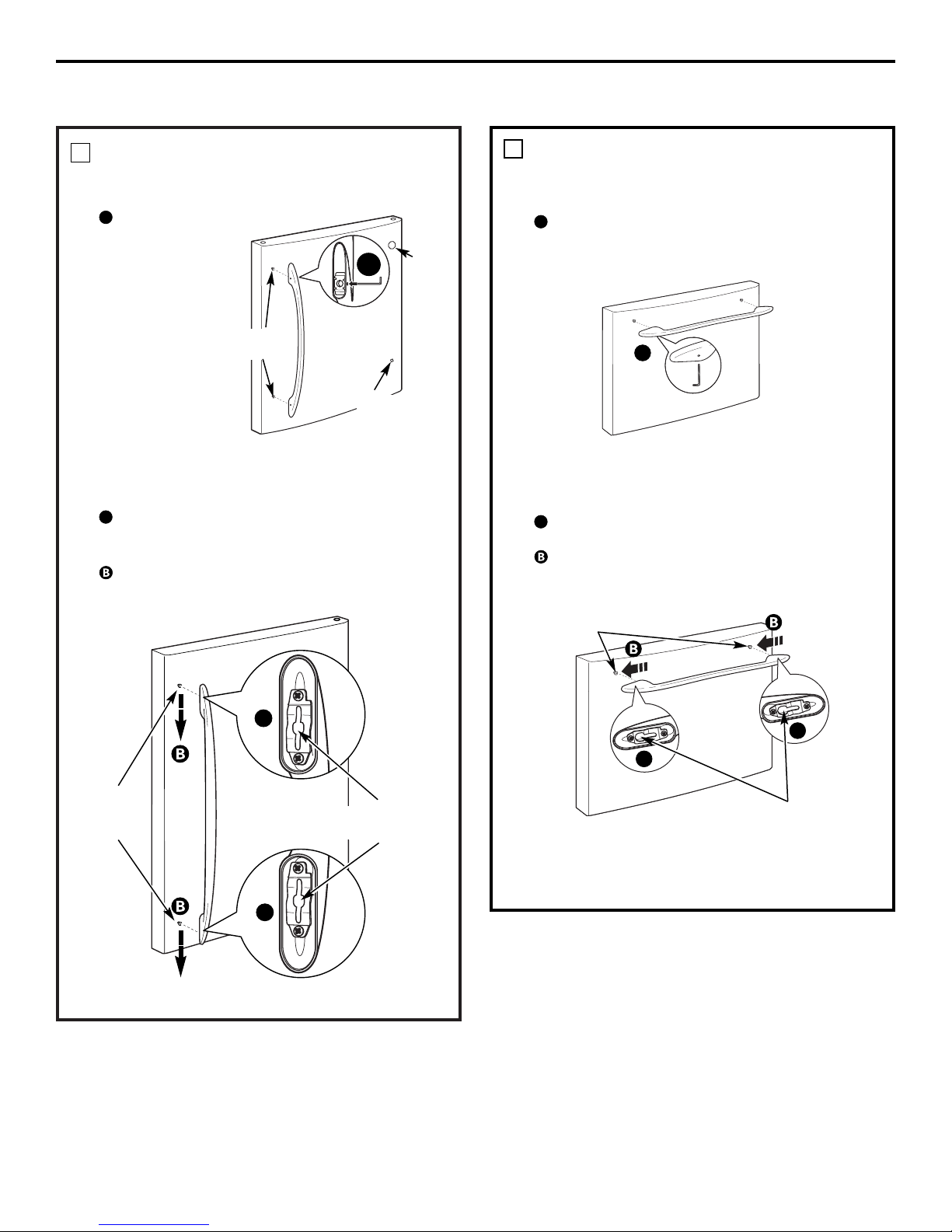
ATTACH THE FREEZER DOOR
HANDLE
Stainless steel handle:
Attach the handle firmly to the mounting
fasteners and tighten the set screws on the
bottom of the handle with a 3/32″ Allen wrench.
Plastic handle:
Attach the handle to the mounting fasteners by
aligning the slots with the mounting fasteners.
Slide it to the left until it is firmly locked into
position.
NOTE: A properly locked handle will be centered
on the freezer.
Installation Instructions
INSTALLING THE REFRIGERATOR
(cont.)
20
ATTACH THE FRESH FOOD
DOOR HANDLE
Stainless steel handle:
Attach the handle
to the handle
mounting
fasteners and
tighten the set
screws with a
3/32″ Allen
wrench.
NOTE: For
Double Door
models follow the
same procedure
on the opposite
door.
Plastic handle:
Attach the handle to the handle mounting
fasteners by aligning the slots with the handle
mounting fasteners.
Slide it down until it is firmly locked into
position.
7
A
Mounting
Fasteners
Plug
Button
Badge
(appearance may vary)
(appearance may vary)
Mounting
fasteners
Slots on back of
handle
A
A
8
Mounting
fasteners
Slots on back
of handle
(appearance may vary)
A
(appearance may vary)
Product Code: GEPDS20MFSWW
www.spaequip.com P: 707-737-1100 F: 707-737-1150 Page 7 of 21
A
A
A
A
A
A
Page 8

LEVEL THE REFRIGERATOR
The leveling legs have 3 purposes:
1) Leveling legs adjust so the door closes
easily when opened about halfway.
(Front of the refrigerator should be
1/4″ [6 mm] higher than the rear of
the refrigerator).
2) Leveling legs adjust so the refrigerator
is firmly positioned on the floor and
does not wobble.
3) Leveling legs serve as a stabilizing
brake to hold the refrigerator securely
in position during operation and
cleaning.
Turn the leveling legs clockwise to raise the
refrigerator, counterclockwise to lower it.
CAUTION: To avoid possible
personal injury or property damage, the
leveling legs must be firmly touching
the floor.
Install the base grille by aligning the
prongs on the back of the grille with the
holes in the cabinet. Push forward until
the grille snaps into place.
9
A
B
Installation Instructions
21
SET THE CONTROLS
Set the controls to the recommended
setting.
10
REMOVE PACKAGING
START ICEMAKER
(icemaker models)
A) Remove all tape, foam and protective
packing from shelves and drawers.
B) Remove the tie downs from the freezer
baskets.
C) Place half width basket onto drawer
slides. See About the freezer section
for instructions.
Set the icemaker power switch to the
I (on) position. The icemaker will not
begin to operate until it reaches its
operating temperature of 15°F (–9°C)
or below. It will then begin operation
automatically. It will take 2–3 days to
fill the ice bin.
NOTE:
In lower water pressure conditions, the
water valve may turn on up to 3 times
to deliver enough water to the icemaker.
11
Power
switch
Freezer
Door (hinge)
models only
Product Code: GEPDS20MFSWW
www.spaequip.com P: 707-737-1100 F: 707-737-1150 Page 8 of 21
Page 9

22
Installation Instructions
REMOVING THE FREEZER DRAWER
(on some models)
REMOVE THE BASKET
Open the freezer drawer until it stops.
The freezer basket rests on a frame inside
the freezer drawer. Lift the basket up at
the back.
Lift the front up and lift the entire basket
up and out of the drawer.
1
A
B
C
REMOVE THE BASE GRILLE
(if needed)
If, after removing the freezer drawer and
refrigerator door, the refrigerator will still
not fit through a doorway, the base grille
can be removed.
Remove the base grille by grasping it at
the bottom and pulling it straight out.
3
The freezer drawer can be removed, if needed,
to fit through tight areas.
Read these instructions completely and carefully.
REMOVE THE DRAWER FRONT
FROM THE SLIDES
Remove the Phillips head screw on each
side of the railing.
DO NOT remove the hex head
screws from the rail assemblies.
2
A
Phillips Screw
DO NOT remove
hex head screws
DO NOT remove
hex head screws
REMOVE THE DRAWER FRONT
FROM THE SLIDES
(cont.)
Lift up on both sides of the freezer drawer
handle to separate the drawer railings
from the rail assemblies.
Set the drawer front on a nonscratching surface.
Push the rail assemblies back into
locking position.
2
B
C
D
Rail
Assembly
Drawer
Assembly
A
Product Code: GEPDS20MFSWW
www.spaequip.com P: 707-737-1100 F: 707-737-1150 Page 9 of 21
A
Page 10

23
Installation Instructions
REPLACING THE FREEZER DRAWER
(on some models)
ATTACH AND SECURE THE
DRAWER FRONT TO THE SLIDES
Pull out the rail assemblies to the full
length on each side of the cabinet.
Locate the slots on the inside of the rail
assemblies near the back.
Insert the hooks at the back of the
drawer railings into the slots on the rail
assemblies.
Lower the front of the drawer, making
sure the tabs on the sides of the railings
fit into the front slots in the rail assemblies.
1
A
B
D
C
REPLACE THE FREEZER BASKET
Replace the lower freezer basket by
lowering it into the frame.
2
Two people may be required to complete
this procedure.
ATTACH AND SECURE THE
DRAWER FRONT TO THE SLIDES
(cont.)
Replace the Phillips head screws on both
rail assemblies.
1
Slot
Rail assembly
Slot
Ta b
Hook
E
Phillips
Screw
Product Code: GEPDS20MFSWW
www.spaequip.com P: 707-737-1100 F: 707-737-1150 Page 10 of 21
Page 11

TOOLS YOU WILL NEED
Installation Instructions
REVERSING THE DOOR SWING
(Single Door Refrigerator Models only)
IMPORTANT NOTES
When reversing the door swing:
NOTE: Door swing is not reversible on some
stainless steel models.
• Read the instructions all the way through
before starting.
• Handle parts carefully to avoid scratching
paint.
• Set screws down by their related parts to
avoid using them in the wrong places.
• Provide a non-scratching work surface for
the doors.
IMPORTANT: Once you begin, do not move
the cabinet until door-swing reversal is
completed.
These instructions are for changing the
hinges from the right side to the left side—if
you ever want to change the hinges back to
the right side, follow these same instructions
and reverse all references to left and right.
• Once door swing is finalized, ensure
the logo badge is properly aligned and
permanently secured to the door by
removing the adhesive cover on the back
side. NOTE: If necessary call Customer
Service for a replacement badge.
Unplug the refrigerator from its electrical
outlet.
Empty all door shelves, including the dairy
compartment.
Putty Knife or
Thin-blade Screwdriver
Masking Tape
Adjustable Wrench
3/8″ and 10 mm Socket
Ratchet/Driver
REMOVE THE
REFRIGERATOR DOOR
Tape the door shut with masking tape.
Remove the hinge cover on top of the
refrigerator door by squeezing it and
pulling it up.
Using a 3/8″ or 10 mm socket
ratchet/driver, remove the bolts securing
the top hinge to the cabinet. Then lift the
hinge straight up to free the hinge pin
from the socket in the top of the door.
Remove the tape and tilt the door away
from the cabinet. Lift the door off the
center hinge pin. Ensure that the white
hinge pin thimble remains on the hinge pin
or inside door hinge pin hole located in the
bottom of the door.
Set the door on a non-scratching surface
with the inside up.
1
A
B
C
D
E
Hinge Cover
Top Hinge
Phillips Screwdriver
24
Product Code: GEPDS20MFSWW
www.spaequip.com P: 707-737-1100 F: 707-737-1150 Page 11 of 21
Page 12

Installation Instructions
REMOVE THE CENTER HINGE PIN
On models with a freezer door, tape the
door shut with masking tape.
Using an adjustable wrench, remove the
center hinge pin.
2
A
B
REMOVE THE FREEZER DOOR
(freezer door models)
Remove the tape and tilt the door away
from the cabinet. Lift the door off the
bottom hinge pin.
NOTE: There is a plastic washer between
the hinge and the top of the freezer door.
Do not lose.
Set the door on a non-scratching surface
with the inside up.
3
A
B
REMOVE CENTER HINGE
Using a 3/8″ or 10 mm socket
ratchet/driver and Phillips head
screwdriver, remove the bolts and screws
securing the center hinge to the cabinet.
Set hinge, bolts, screws, washer (on
freezer door models) and hinge pin aside.
On models with a freezer drawer, skip to
Step 7.
4
TRANSFER BOTTOM HINGE
BRACKET
(freezer door models)
Remove the base grille by grasping it at
the bottom and pulling it straight out.
Using a 3/8″ or 10 mm socket
ratchet/driver, remove the screws
securing the bottom hinge bracket to the
cabinet.
Using an adjustable wrench, remove the
hinge pin and washer(s) from the right
side of the bracket and install on the left.
5
A
B
C
Washer(s)
25
Product Code: GEPDS20MFSWW
www.spaequip.com P: 707-737-1100 F: 707-737-1150 Page 12 of 21
Page 13

Installation Instructions
REVERSING THE DOOR SWING
(cont.)
TRANSFER BOTTOM HINGE
BRACKET
(freezer door models, cont.)
Install the bottom hinge bracket on the
left side of the cabinet.
Replace the base grille by aligning the
prongs on the back of the grille with the
holes in the cabinet. Push forward until
the grille snaps into place.
5
D
E
TRANSFER FREEZER DOOR STOP
(freezer door models)
Remove the door stop on right side of the
bottom of the freezer door by removing
the two screws.
Move the plastic hinge hole thimble to the
opposite hole.
Install the door stop on the left side.
6
A
B
C
Bottom of Freezer Door
(Right Side)
Bottom of Freezer Door
(Left Side)
A
INSTALL CENTER HINGE
Transfer the plug button and screws in
the hinge holes on the left side to the
right side.
Install the center hinge on the left side.
7
A
B
HANG THE FREEZER DOOR
(freezer door models)
Lower the freezer door onto the bottom
hinge pin, then shut the door, making
sure to align the door with the cabinet.
Make sure the gasket on the door is flush
against the cabinet.
8
26
Product Code: GEPDS20MFSWW
www.spaequip.com P: 707-737-1100 F: 707-737-1150 Page 13 of 21
Page 14

27
Installation Instructions
INSTALL CENTER HINGE PIN
Install the center hinge pin.
NOTE: On models with a freezer door,
be sure to put the washer between the
top of the freezer door and the bottom
of the center hinge.
9
A
Freezer Door Models Freezer Drawer Models
TRANSFER REFRIGERATOR
DOOR STOP
Remove the door stop on right side of
the bottom of the refrigerator door by
removing the two screws.
Move the plastic hinge hole thimble to
the opposite hole.
Install the door stop on the left side,
making sure to line up the screw holes
in the door stop with the holes in the
bottom of the door.
10
A
B
C
Bottom of
Refrigerator Door
(Right Side)
Bottom of
Refrigerator Door
(Left Side)
A
TRANSFER REFRIGERATOR
DOOR HANDLE TO RIGHT
Refer to Remove the Fresh Food Door
Handle and Attach the Fresh Food Door
Handle sections for instructions.
11
REHANG REFRIGERATOR DOOR
Lower the refrigerator door onto the
center hinge pin. Ensure that the white
hinge pin thimble is on the center hinge
pin or inside door hinge pin hole located
in the bottom of the door.
Insert the top hinge pin into the hinge
hole on top of the refrigerator door. Make
sure the door is aligned with the cabinet.
Attach the hinge to the top of the cabinet
loosely with the bolts.
Make sure the gasket on the door is
flush against the cabinet and is not
folded. Support the door on the handle
side and make sure the door is straight
and the gap between the doors is even
across the front. While holding the door
in place, tighten the top hinge bolts.
Replace the hinge cover.
12
A
B
C
Product Code: GEPDS20MFSWW
www.spaequip.com P: 707-737-1100 F: 707-737-1150 Page 14 of 21
Page 15

TOOLS YOU WILL NEED
Installation Instructions
REMOVING THE DOORS
(Double Door Refrigerator Models only)
IMPORTANT NOTES
NOTE: Door swing is not reversible.
• Read the instructions all the way through
before starting.
• Handle parts carefully to avoid scratching
paint.
• Set screws down by their related parts to
avoid using them in the wrong places.
• Provide a non-scratching work surface for
the doors.
IMPORTANT: Once you begin, do not move
the cabinet.
These instructions are for removing the
doors.
Unplug the refrigerator from its electrical
outlet.
Empty all door shelves, including the dairy
compartment.
Putty Knife or
Thin-blade Screwdriver
Masking Tape
Adjustable Wrench
3/8″ and 10 mm Socket
Ratchet/Driver
REMOVE THE
REFRIGERATOR DOORS
Tape the doors shut with masking tape.
Remove the screw securing each hinge
cover, lift the hinge cover and place to
the side on top of the refrigerator.
Carefully disconnect the wire connector
and remove the screw securing the
ground wire.
Using a 3/8″ or 10 mm socket
ratchet/driver, remove the bolts securing
the top hinge to the cabinet. Then lift the
hinge straight up to free the hinge pin
from the hinge pin hole in the top of the
door. Carefully remove the wires from the
hinge pin through the slot.
Remove the tape and tilt the door away
from the cabinet. Lift the door off the
center hinge pin. Ensure that the white
hinge pin thimble remains on the center
hinge pin or inside door hinge pin hole
located in the bottom of the door.
Set the door on a non-scratching surface
with the inside up.
1
A
B
D
E
Top Hinge
Phillips Screwdriver
28
Hinge Cover
Wire
Connector
Ground Wire
C
Hinge Pin
Slot
Hinge Pin
Thimble
PARTS INCLUDED
C Spacer (on some models)
(appearance may vary)
(appearance may vary)
Product Code: GEPDS20MFSWW
www.spaequip.com P: 707-737-1100 F: 707-737-1150 Page 15 of 21
Page 16

Installation Instructions
REMOVE CENTER HINGE
Using a 3/8″ or 10 mm socket
ratchet/driver and Phillips head
screwdriver, remove the bolts and screw
securing the center hinge to the cabinet.
Set hinge, bolts, and screw aside.
2
29
REMOVE OPPOSITE DOOR
Follow the same procedure on the
opposite door.
3
REMOVE FREEZER DRAWER
Refer to the Removing the Freezer Drawer
section for instructions.
4
Product Code: GEPDS20MFSWW
www.spaequip.com P: 707-737-1100 F: 707-737-1150 Page 16 of 21
Page 17

Installation Instructions
REPLACING THE DOORS
(Double Door Refrigerator Models only)
INSTALL CENTER HINGE
Install the center hinge on each side.
REHANG REFRIGERATOR DOORS
Lower the refrigerator door onto the
center hinge pin. Ensure that the white
hinge pin thimble is on the center hinge
pin or inside door hinge pin hole located
in the bottom of the door.
Securely tape the door shut with masking
tape or have a second person support
the door.
Route wires through top hinge pin slot.
Insert the top hinge pin into the hinge hole
on top of the refrigerator door. Make sure
the door is aligned with the cabinet and
opposite door. Attach the hinge to the top
of the cabinet loosely with the bolts.
Reconnect the wire connector and
reconnect the ground wire using the screw
removed earlier. Ensure that the wire
connector is fully engaged.
IMPORTANT: The ground wire must be
reinstalled to ensure a proper ground.
A
B
REHANG REFRIGERATOR DOORS (CONT.)
Make sure the gasket on the door is
flush against the cabinet and is not folded.
Make sure the door is straight and the gap
between the doors is even across the front.
While holding the aligned door in place,
tighten the top hinge bolts. Replace the
hinge cover and screw.
E
C
Hinge Pin
Thimble
Top Hinge
Pin Slot
Top Hinge
Pin
Wire
Connector
Ground Wire
Top Hinge Bolts
Hinge Cover
ALIGN DOUBLE DOORS
If the top of the doors are uneven, first
try to raise the lowest door by turning the
leveling leg on the same side as the door
until the doors are even. If the unit rocks,
re-adjust the leveling legs to the extent
that the unit is stable.
If the doors remain uneven, use a C spacer
to align the doors. While lifting the door
on the hinge side with one hand, insert a
C spacer with pliers. Continue to add C
spacers until the doors are even.
C Spacer
REPLACE FREEZER DRAWER
Refer to the Replacing the Freezer Drawer
section for instructions.
5
D
30
REPLACE OPPOSITE DOOR
Follow the same procedure on the
opposite door.
(appearance may vary)
(appearance may vary)
4
3
2
2
1
Product Code: GEPDS20MFSWW
www.spaequip.com P: 707-737-1100 F: 707-737-1150 Page 17 of 21
Page 18

Installation Instructions
31
INSTALLING THE WATER LINE (ICEMAKER MODELS)
Recommended copper water supply kits are
WX8X2, WX8X3 or WX8X4, depending on the
amount of tubing you need. Approved plastic
water supply lines are GE SmartConnect
™
Refrigerator Tubing (WX08X10002,
WX08X10006, WX08X10015 and
WX08X10025).
When connecting your refrigerator to a GE
Reverse Osmosis Water System, the only
approved installation is with a GE RVKit. For
other reverse osmosis water systems, follow
the manufacturer’s recommendations.
If the water supply to the refrigerator is from
a Reverse Osmosis Water Filtration System
AND the refrigerator also has a water filter,
use the refrigerator’s filter bypass plug. Using
the refrigerator’s water filtration cartridge in
conjunction with the RO filter can result in
hollow ice cubes.
This water line installation is not warranted
by the refrigerator or icemaker manufacturer.
Follow these instructions carefully to
minimize the risk of expensive water damage.
Water hammer (water banging in the pipes)
in house plumbing can cause damage to
refrigerator parts and lead to water leakage
or flooding. Call a qualified plumber to correct
water hammer before installing the water
supply line to the refrigerator.
To prevent burns and product damage, do not
hook up the water line to the hot water line.
If you use your refrigerator before connecting
the water line, make sure the icemaker power
switch is in the O (off) position.
Do not install the icemaker tubing in areas
where temperatures fall below freezing.
When using any electrical device (such as a
power drill) during installation, be sure the
device is double insulated or grounded in a
manner to prevent the hazard of electric
shock, or is battery powered.
All installations must be in accordance with
local plumbing code requirements.
BEFORE YOU BEGIN
WHAT YOU WILL NEED
• Copper or GE SmartConnect™Refrigerator
Tubing kit,1/4″ outer diameter to connect
the refrigerator to the water supply. If using
copper, be sure both ends of the tubing are
cut square.
To determine how much tubing you need:
measure the distance from the water valve
on the back of the refrigerator to the water
supply pipe. Then add 8′ (2.4 m). Be sure
there is sufficient extra tubing (about 8′ [2.4 m]
coiled into 3 turns of about 10″ [25 cm]
diameter) to allow the refrigerator to move
out from the wall after installation.
GE SmartConnect
™
Refrigerator Tubing Kits
are available in the following lengths:
2′ (0.6 m) – WX08X10002
6′ (1.8 m) – WX08X10006
15′ (4.6 m) – WX08X10015
25′ (7.6 m) – WX08X10025
Be sure that the kit you select allows at least
8′ (2.4 m) as described above.
Product Code: GEPDS20MFSWW
www.spaequip.com P: 707-737-1100 F: 707-737-1150 Page 18 of 21
Page 19

INSTALLING THE WATER LINE
(CONT.)
NOTE: The only GE approved plastic tubing
is that supplied in GE SmartConnect
™
Refrigerator Tubing kits. Do not use any
other plastic water supply line because the
line is under pressure at all times. Certain
types of plastic will crack or rupture with age
and cause water damage to your home.
• A GE water supply kit (containing tubing,
shutoff valve and fittings listed below) is
available at extra cost from your dealer or
from Parts and Accessories, 800.626.2002
(in Canada 1.888.261.3055).
• A cold water supply. The water pressure must
be between 20 and 120 p.s.i. (1.4–8.1 bar).
• Power drill.
• 1/2″ or adjustable wrench.
• Straight and Phillips blade screwdriver.
• Two 1/4″ outer diameter compression nuts
and 2 ferrules (sleeves)—to connect the
copper tubing to the shutoff valve and the
refrigerator water valve.
OR
• If you are using a GE SmartConnect
™
Refrigerator Tubing kit, the necessary
fittings are preassembled to the tubing.
• If your existing copper water line has a
flared fitting at the end, you will need an
adapter (available at plumbing supply
stores) to connect the water line to the
refrigerator OR you can cut off the flared
fitting with a tube cutter and then use a
compression fitting. Do not cut formed end
from GE SmartConnect
™
Refrigerator tubing.
• Shutoff valve to connect to the cold water
line. The shutoff valve should have a water
inlet with a minimum inside diameter of
5/32″ at the point of connection to the COLD
WATER LINE. Saddle-type shutoff valves are
included in many water supply kits. Before
purchasing, make sure a saddle-type valve
complies with your local plumbing codes.
WHAT YOU WILL NEED (CONT.)
SHUT OFF THE MAIN WATER
SUPPLY
Turn on the nearest faucet long enough
to clear the line of water.
Install the shutoff valve on the nearest
frequently used drinking water line.
1
Choose a location for the valve that is
easily accessible. It is best to connect into
the side of a vertical water pipe. When it is
necessary to connect into a horizontal
water pipe, make the connection to the
top or side, rather than at the bottom,
to avoid drawing off any sediment from
the water pipe.
CHOOSE THE VALVE LOCATION
2
DRILL THE HOLE FOR THE VALVE
3
Drill a 1/4″ hole in the water pipe (even if
using a self-piercing valve), using a sharp
bit. Remove any burrs resulting from
drilling the hole in the pipe.
Take care not to allow water to drain into
the drill.
Failure to drill a 1/4″ hole may result in
reduced ice production or smaller cubes.
Installation Instructions
32
Product Code: GEPDS20MFSWW
www.spaequip.com P: 707-737-1100 F: 707-737-1150 Page 19 of 21
Page 20

Installation Instructions
Place the compression nut and ferrule
(sleeve) for copper tubing onto the end
of the tubing and connect it to the
shutoff valve.
Make sure the tubing is fully inserted
into the valve. Tighten the compression
nut securely.
For plastic tubing from a GE
SmartConnect
™
Refrigerator Tubing kit,
insert the molded end of the tubing into
the shutoff valve and tighten compression
nut until it is hand tight, then tighten one
additional turn with a wrench.
Overtightening may cause leaks.
NOTE: Commonwealth of Massachusetts
Plumbing Codes 248CMR shall be adhered
to. Saddle valves are illegal and use is not
permitted in Massachusetts. Consult with
your licensed plumber.
CONNECT THE TUBING
TO THE VALVE
7
Saddle-Type
Shutoff Valve
Compression Nut
Packing Nut
Outlet Valve
Ferrule (sleeve)
Turn the main water supply on and flush
out the tubing until the water is clear.
Shut the water off at the water valve after
about one quart (1 liter) of water has been
flushed through the tubing.
FLUSH OUT THE TUBING
8
SmartConnect
™
Tubing
Fasten the shutoff valve to the cold water
pipe with the pipe clamp.
NOTE: Commonwealth of Massachusetts
Plumbing Codes 248CMR shall be adhered
to. Saddle valves are illegal and use is not
permitted in Massachusetts. Consult with
your licensed plumber.
FASTEN THE SHUTOFF VALVE
4
Tighten the clamp screws until the sealing
washer begins to swell.
NOTE: Do not overtighten or you may
crush the tubing.
TIGHTEN THE PIPE CLAMP
5
Pipe Clamp
Vertical Cold Water Pipe
Saddle-Type
Shutoff Valve
Washer
Inlet End
Pipe Clamp
Clamp
Screw
Route the tubing between the cold water
line and the refrigerator.
Route the tubing through a hole drilled in
the wall or floor (behind the refrigerator or
adjacent base cabinet) as close to the wall
as possible.
NOTE: Be sure there is sufficient extra
tubing (about 8
′
[2.4 m] coiled into 3 turns
of about 10″ [25 cm] diameter) to allow the
refrigerator to move out from the wall after
installation.
ROUTE THE TUBING
6
To complete the installation of the refrigerator,
go back to Step 1 in Installing the Refrigerator.
33
Product Code: GEPDS20MFSWW
www.spaequip.com P: 707-737-1100 F: 707-737-1150 Page 20 of 21
Page 21

Consumer Support
Troubleshooting Tips
Operating Instructions Safety InstructionsInstallation Instructions
Normal operating sounds.
Before you call for service…
Troubleshooting Tips
Save time and money! Review the charts on the following
pages first and you may not need to call for service.
Newer refrigerators sound different from older refrigerators.
Modern refrigerators have more features and use newer technology.
HUMMM...
WHOOSH...
■
The new high efficiency compressor may run faster and longer
than your old refrigerator and you may hear a high-pitched
hum or pulsating sound while it is operating.
■
You may hear a whooshing sound when the doors close. This is
due to pressure equalizing within the refrigerator.
■
You may hear the fans spinning at high speeds. This happens
when the refrigerator is first plugged in, when the doors are
opened frequently or when a large amount of food is added to
the refrigerator or freezer compartments. The fans are helping
to maintain the correct temperatures.
■
The fans change speeds in order to provide optimal cooling
and energy savings.
CLICKS, POPS,
CRACKS and SNAPS
■
You may hear cracking or popping sounds when the
refrigerator is first plugged in. This happens as the refrigerator
cools to the correct temperature.
■
The freezer control will click when starting or stopping the
compressor.
■
Defrost timer snapping in and out of the defrost cycle.
■
Expansion and contraction of cooling coils during and after
defrost can cause a cracking or popping sound.
■
On models with an icemaker, after an icemaking cycle, you
may hear the ice cubes dropping into the ice bucket.
■
On models with a dispenser, during water dispense, you
may hear the water lines move at initial dispense and after
dispenser button is released.
WATER SOUNDS
■
The flow of refrigerant through the freezer cooling coils may
make a gurgling noise like boiling water.
■
Water dropping on the defrost heater can cause a sizzling,
popping or buzzing sound during the defrost cycle.
■
A water dripping noise may occur during the defrost cycle as
ice melts from the evaporator and flows into the drain pan.
■
Closing the door may cause a gurgling sound due to pressure
equalization.
Do you hear what I hear? These sounds are normal.
Problem Possible Causes What To Do
Refrigerator does not Refrigerator in defrost cycle. •Wait about 30 minutes for defrost cycle to end.
operate
Control in 0 (off) position. • Move the control to a temperature setting.
Refrigerator is unplugged. • Push the plug completely into the outlet.
The fuse is blown/circuit • Replace fuse or reset the breaker.
breaker is tripped.
Vibration or rattling Leveling legs need adjusting. • See Level the Refrigerator.
(slight vibration
is normal)
For additional information on normal
icemaker operating sounds, see the
About the automatic icemaker section.
34
Product Code: GEPDS20MFSWW
www.spaequip.com P: 707-737-1100 F: 707-737-1150 Page 21 of 21
 Loading...