

Page 1
Global Sales & Service Network
GEP
4.6-10KW SINGLE PHASE
USER MANUAL
99 Walker Street North Sydney NSW 2060
T: +61 284159833
support.au@gesolarinverter.com
sales.au@gesolarinverter.com
* GE is a registered trademark of General Electric Company and is used under license by Jiangsu GoodWe Power Supply Technology Co., Ltd.
© 2020 All Rights Reserved
340-00468-02
Ver.1.2
SOLAR INVERTER
www.gesolarinverter.com
Page 2

1 Symbols ........................................................................................................................... 01
2 Safety Measures & Warning ................................................................ 02
3 Product Introduction ........................................................................................ 04
3.1 Inverter Overview .................................................................................................................. 04
3.2 Package .................................................................................................................................... 05
4 Installation .................................................................................................................... 06
4.1 Mounting Instructions .......................................................................................................... 06
4.2 Equipment Installation ........................................................................................................ 06
4.3 Electrical Connection .......................................................................................................... 08
4.4 Communication Connection ............................................................................................. 12
5 System Operation .............................................................................................. 16
5.1 LCD Panel ............................................................................................................................... 16
5.2 User Interface and System Configuration .................................................................... 17
5.3 Wi-Fi/LAN Reset & Wi-Fi/LAN Reload ........................................................................... 22
5.4 Precaution for Initial Startup .............................................................................................. 22
5.5 Special Adjustable Setpoints ............................................................................................ 23
6 Troubleshooting .................................................................................................... 26
7 Caution............................................................................................................................ 28
7.1 Checking The DC Switch.............................................................................. 28
7.2 Checking The Electrical Connection............................................................. 28
TABLE OF CONTENTS
8 Technical Parameters .................................................................................. 29
Page 3
1 Symbols
2 Safety Measures & Warning
4
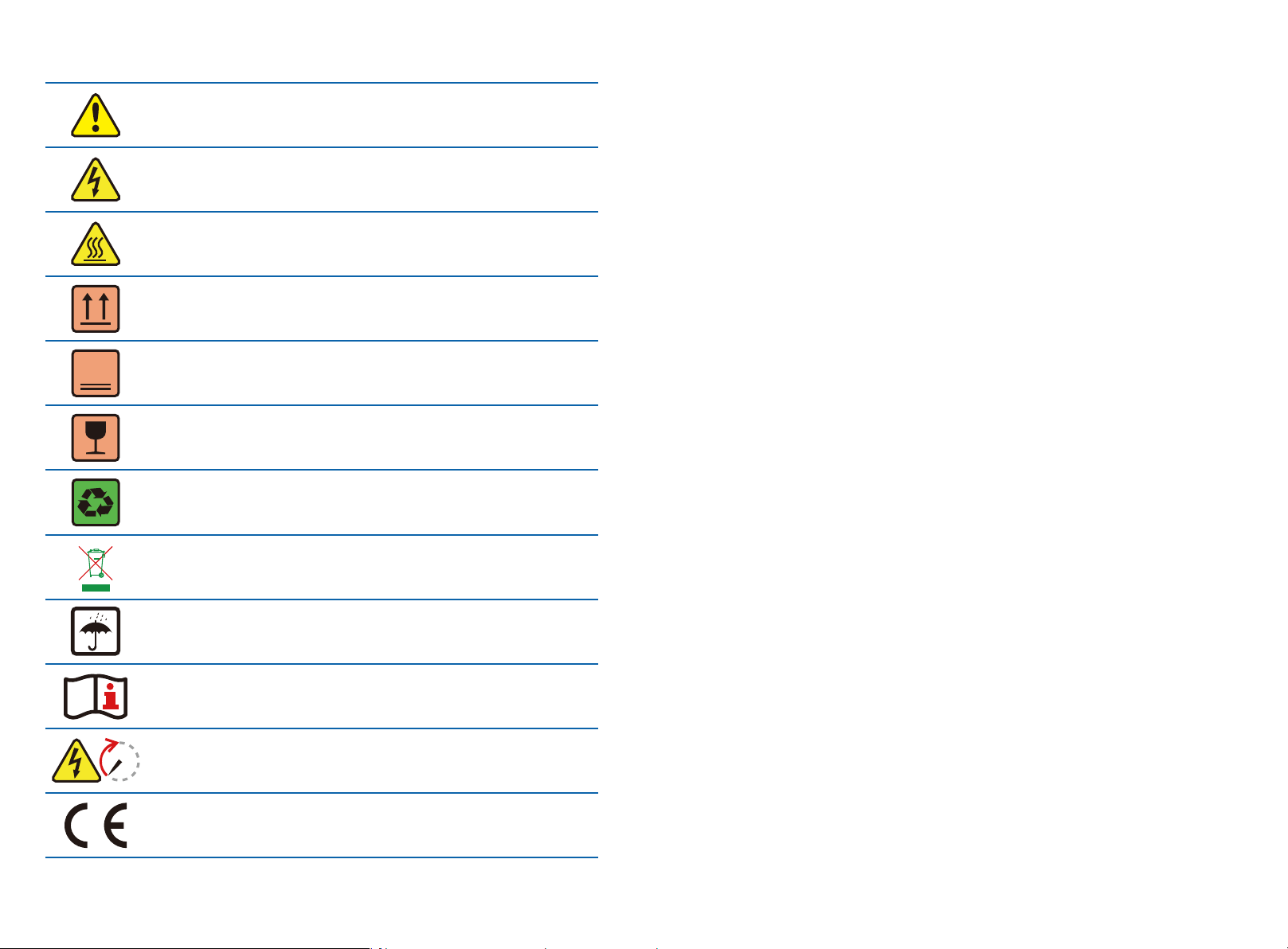
Failure to observe a warning indicated in this manual may result in
injury.
Danger of high voltage & electric shock.
Don't touch, hot surface!
This side up. The package must always have the arrows point up.
No more than four identical packages stacked on each other.
Fragile.
Recyclable materials.
Special disposal instructions.
Keep Dry.
Refer to operation instructions.
Wait at least 5 minutes after disconnecting the inverter before
handling internal parts.
5min
CE mark.
• The GEP inverter strictly conforms and has been tested according to international safety
regulations.
• The manufacturer strongly advises installers to follow local safety regulations during
commissioning, operation and maintenance of the GEP inverter. Improper operation may result in
electric shocks or damage to equipment and property.
• The installation, maintenance and connection of the inverters must be performed by qualified
personnel, in compliance with local electrical standards, regulations and following the regulations
of the local power suppliers, companies and related authorities.
• If the GEP inverter is unpacked but not put into use immediately, please put it back to the original
package with the desiccant bag and seal it with tape.
• To avoid electric shocks, the DC input and AC output port of the inverters must be disconnected
for at least 5 minutes before performing any installation or maintenance.
• The temperature of some components of the inverters may exceed 60℃ during operation. To
avoid burns, do not touch the inverter during operation. Let the inverter cool before operating.
• Keep children away from the inverter.
• Touching or changing inverter components without following manual instructions may cause
personal injury, damage the inverters and could ultimately invalidate the warranty.
• The electronic components of the inverter could be damaged by static electricity. Appropriate
methods must be adopted to prevent such damage, otherwise the warranty may be null and void.
• Ensure the output voltage of the proposed PV array is lower than the maximum rated input voltage
of the inverter, otherwise the inverter may be damaged and the warranty may be null and void.
• When exposed to sunlight, the PV array generates dangerously high DC voltage. We strongly
advise operators strictly follow instructions and avoid actions that put lives at risk.
• The PV modules should have as a minimum an IEC61730 class A rating protection.
• If the equipment is used in a way not authorized by the manufacturer, the equipment built-in
protections may be damaged.
• In order to achieve complete equipment isolation: turn off the AC switch first, then turn off the DC
switch.
• Do not insert or pull the AC or DC terminals when the inverter is in operation.
• An Arc Fault Detector is recommended to be installed on the DC side of an earthing photovltaic
system.
• The inverter can exclude the possibility of DC residual currents to 6mA in the system, Where an
external RCD is required in addition to the built-in RCMU, type A RCD must be used to avoid
tripping.
• The PV is not grounded as default configuration.
01 02
Page 4
To ensure IP65 protection is maintained, please make sure that the inverter is rigorously
packed and its components are sealed properly. GE strongly suggests to install the
inverter at most one day after it has been unpacked. If this is not the case and the
installation takes longer, please re-seal all the unused terminals and ensure that the
inverter and its components are not exposed to water or dust.
The manufacturer provides a standard warranty which comes with the inverter product and
prepaid warranty extension solution for our customer. For further details please visit:
www.gesolarinverter.com
3 Product Introduction
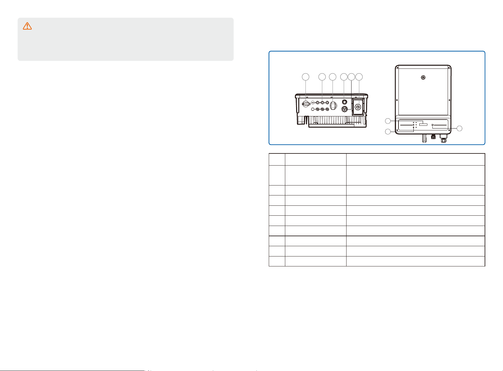
3.1 Inverter Overview
Bottom view
5
Description
Item
1 2 3 4 6
Name
Front view
7
8
9
1
DC Switch
2
PV Input Terminal
3
Wi-Fi /LAN Module (Optional)
4
DRED Function (Optional)
5
CT and RS485 (Optional)
6
AC Output Terminal
LCD Display
7
8
Indicator Lights
9
Buttons
During normal operation, it is in "on" state and it can shut down
the inverter after the inverter is disconnected from the grid by the AC breaker.
For PV string connection
For Wi-Fi or LAN communication
For DRED communication
For CT and RS485 Communication
For AC cable connection
Inverter operation data overview and parameter configuration.
Display the state of the inverter
For configuration and viewing parameters.
03 04
Page 5
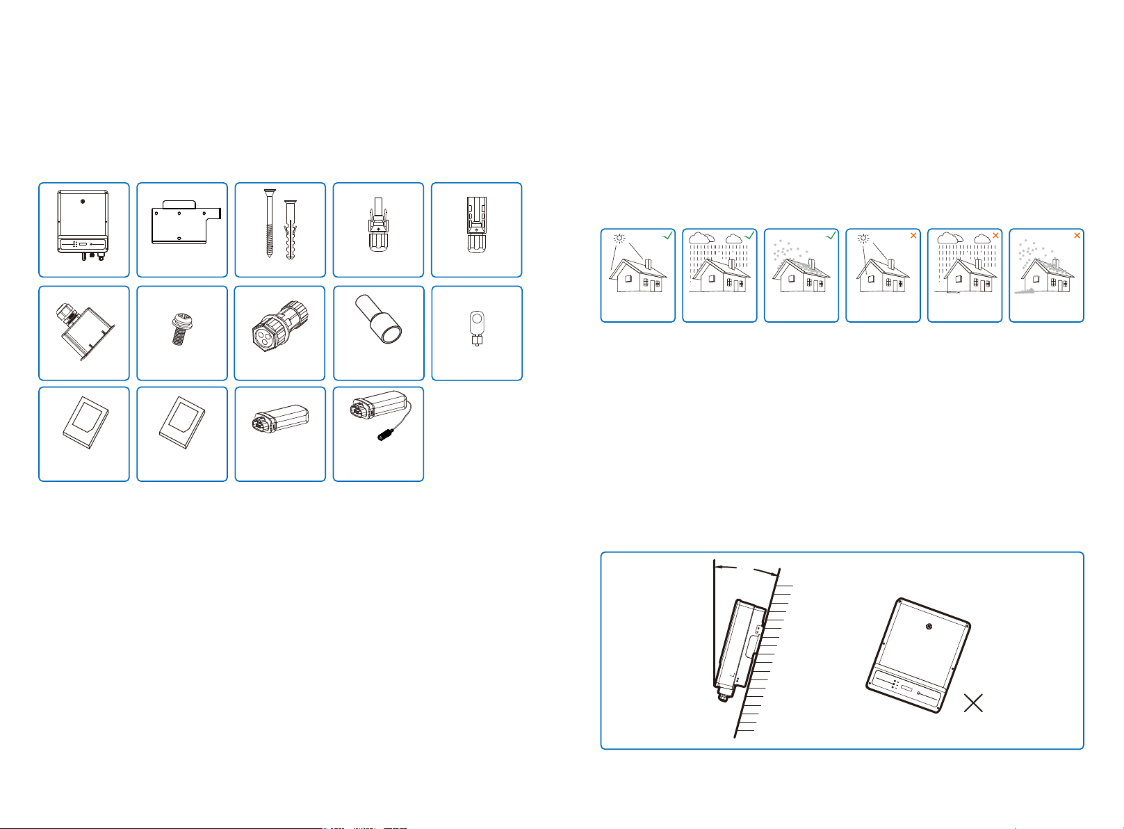
3.2 Package
The unit is thoroughly tested and strictly inspected before delivery. Damage may still occur during
shipping.
1. Check the package for any visible damage upon receiving.
2. Check the inner contents for damage after unpacking.
3. Check the package list below.
4 Installation
4.1 Mounting Instructions
1. In order to achieve optimal performance, the ambient temperature should be lower than 45℃.
2. For easy maintenance, we suggest to install the inverter at eye level.
3. Inverters should not be installed near flammable and explosive items. Strong electro-magnetic
charges should be kept away from installation site.
4. Product label and warning symbols should be located and placed in a manner that can be easily
ready by users.
5. Ensure the inverter is installed in a location that is protected from direct sunlight, rain and snow.
Wall-mounted
Bracket x1
AC Terminal x1
User Manual x1 Wi-Fi/LAN Configuration
Grounding Screw x2
Instruction x1
Expansion Bolts x6
CT/RS485 Terminal x1
Wi-Fi Module
(Wi-Fi Communication
Only) x1
Positive DC Plug x3 Negative DC Plug x3Inverter
Pin Terminal x4
LAN Module
(LAN Communication
Only) x1
PE Terminal x1
Keep away
from sunlight
Keep dry
Keep it clear
of snow
Sun Rain
Accmulated snow
4.2 Equipment Installation
4.2.1 Select installation location
Please take the following points into consideration when you selecting a proper location to install
inverter.
1. Please choose appropriate mounting methods and installation location taking both the weight
and dimension of inverter into account.
2. The location must be well ventilated and sheltered from direct sunlight.
3. Install the inverter vertically or with a backward tilt up to 15 degrees maximum. No lateral tilt is
allowed. The inverter should not be tilted sideways. The area of the connectors should point
downwards.
Maximum
15°
05 06
Page 6
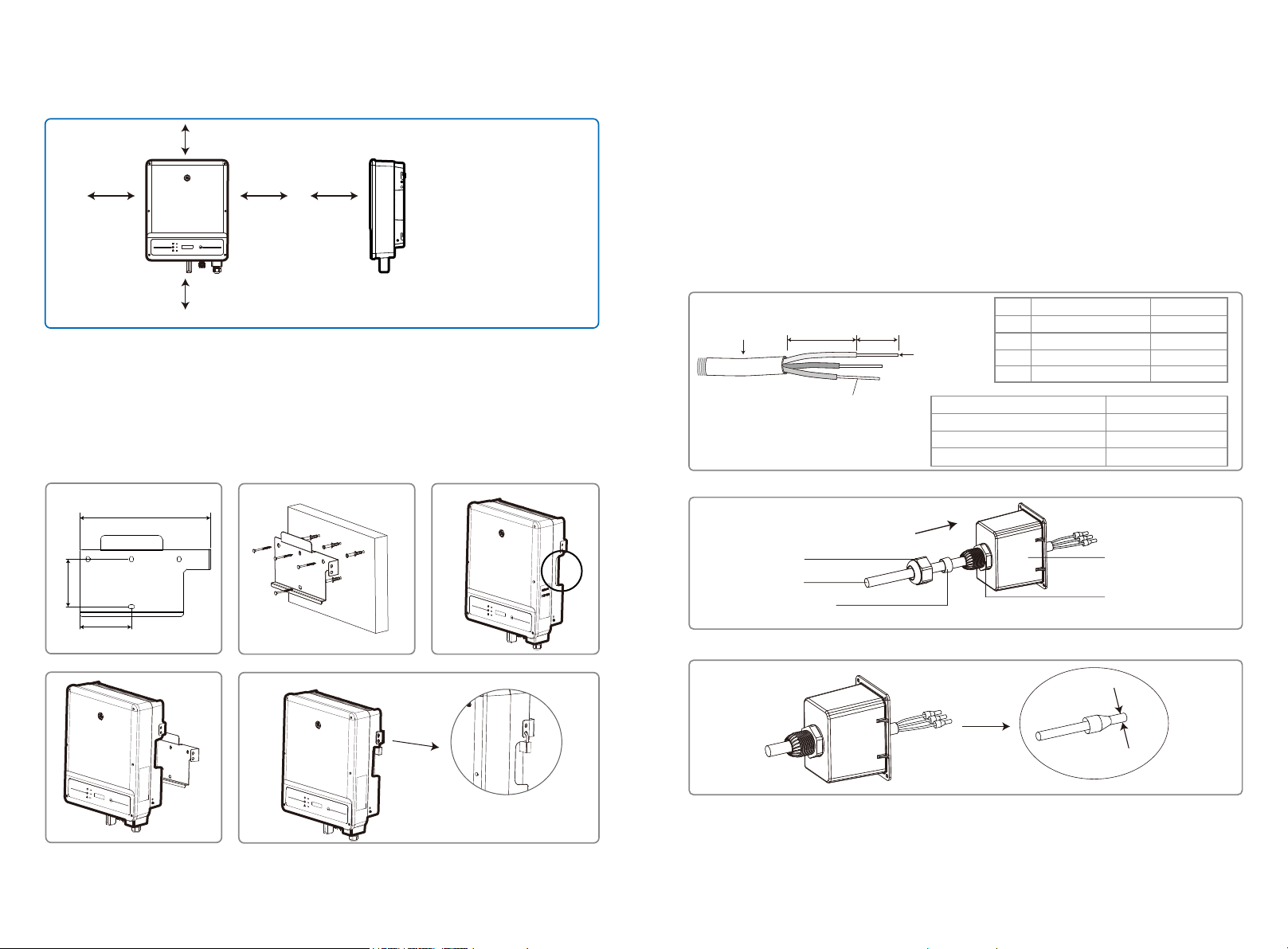
4. To guarantee the enough space for heat dissipation and facilitate the installation and removal,
the spacing around the inverter should meet the requirements as demonstrated in the following
illustration.
300mm
200mm200mm
300mm
Upward
Downward
Front
Both sides
-------------300mm
---------500mm
----------------300mm
----------200mm
4.3 Electrical Connection
4.3.1 AC Side Connection
1. When connecting the inverter, please make sure to adjust the voltage and the frequency in
compliance with grid regulations and the specifications of the inverter installed.
2. Add a breaker or fuse to the AC side. Please note that the specification should be more than 1.25
times the rated AC output current.
3. The PE wire of the inverter should be connected to earth. Make sure the impedance of neutral
wire and earth wire is less than 10Ω.
4. Disconnect the breaker or fuse between the inverter and the utility.
5. When laying the AC Wire make sure that the protective earthing conductor is not strained.
500mm
4.2.2 Mounting procedure
1. Use the wall-mount bracket as a template and drill holes with 10mm in diameter and 80 mm in
depth on the wall.
2. Fix the wall-mount bracket on the wall with the expansion bolts in the accessories bag.
3. Hold the inverter by the side groove.
4. Mount the inverter onto the wall-mount bracket.
329mm
120mm
Grade
Description
A
A B
Annealed copper wire
C
D
Inverter
GEP4.6-1C-10/GEP5.0-1C-10
GEP7.0-1-10
GEP8.5-1-10/GEP9.0-1-10/GEP10-1-10
Outside diameter
B
Separated wire length
C
Conductor wire length
D
Conductor core section
Step 1: Put AC cable through terminal cover follow the sequence.
Screw cap
Cables
Single hole
seal ring
Step 2: Press the 3 connectors on cable conductor core tightly.
Value
13~18mm
20~25mm
7~9mm
2.5~10mm
Conductor core section
2
2.5mm
2
4mm
2
10mm
AC sheet cover
The insulator
2
A lock could be used for anti-theft if it is
necessary for individual requirement.
07 08
Page 7

Step 3: Connect the assembled AC cables into AC terminals with fastening torque about
2.0-2.5N.m. Then lock the cover and screw the cap.
Screwing torque 2.0-2.5N.m
There are four types of DC connectors, DEVALAN, MC4, AMPHENDL H4 and QC4.10 series.
DEVALAN SERIES MC4 SERIES
AMPHENOL SERIES QC4.10 SERIES
4.3.2 AC circuit breaker and leakage current protection device
Please install an independent two pole circuit breaker to protect the inverter and make sure it is
safe to disconnect it from the grid.
In addition to the built-in RCMU, an external RCD is required to ensure that the inverter system
does not carry DC residual currents. To avoid tripping, the types A can be used.
Inverter Model
GEP4.6-1C-10/GEP5.0-1C-10
GEP7.0-1-10/GEP8.5-1-10
GEP9.0-1-10/GEP10-1-10
Recommended Circuit Breaker Specifications
32A
50A
63A
Note: it is not recommended that multiple inverters share a single circuit breaker.
The integrated leakage current detection device of the inverter can detect external leakage current
in real time. When the detected leakage current exceeds the limit value, the inverter will quickly
disconnect from the grid. If the leakage current protection device is installed externally, the action
current should be 300mA or higher.
4.3.3 DC Side Connection
1. Before connecting the PV strings, please ensure the plug connectors have the correct polarity.
Incorrect polarity has the potential risk to cause permanent damage to the inverter.
2. The open circuit voltage of the PV strings cannot exceed the maximum input voltage of the
inverter.
3. Only the DC connectors supplied by the manufacturer are suitable for use.
4. The positive and negative pole should not be connected to the PE wire (ground wire). Not
following this instruction may cause damage to the inverter.
5. Red wire represents positive, black wire represents negative.
6. For the GE series the minimum insulation resistance to the ground of the PV panels must
exceed 20kΩ(R=600/30mA). There is risk of electric shock if this minimum resistance requirement
is not met.
Note: The actual DC connector used is shown in the accessory box.
DC cable specification:
A B
Label
Description
A
External diameter of wire stock
B
Please use solar PV cable in DC
C
connection.(4mm PV1-F wire recommended)
Cross-sectional area of conductor material
C
Length of bare wire
The installation method of DC connector.
Positive connector
Negative connector
MC4 & QC4.10 DEVALAN & AMPHENOL
Do not crimp wire
into the limit buckle.
Please use special tools to do crimping
Inverter side
Value
4~5mm
2.5~4mm
About 7mm
2
Note:There is risk of burning if the DC connector is not connect tightly,you can hear the
“Click” sound to confirm the connectivity.
09 10
Page 8

4.3.4 Earth Terminal Connection
The inverter is equipped with earth terminal according to the requirement of EN 50178.
All non-current carrying exposed metal parts of the equipment and other enclosures in the PV
power system must be grounded.
Please follow the steps below to connect "PE" cable to ground.
Step 1
Strip the wire insulation sheet of a suitable length with a wire stripper.
L1
L2 = L1 + (1~2mm)
Step 2
Insert the stripped wire into the terminal and compress it tightly by crimping pliers.
Step 3
Fix the earth wire
In order to improve the corrosion resistance of the terminal, it is recommended to apply
silica gel on the earth terminal for corrosion protection after the grounding cable connec-
tion is completed.
4.4 Communication Connection
After the replacement of the Wi-Fi/LAN, the new module can work only after restarting PV array
connected to the inverter.
This port is used for connection of Wi-Fi or LAN module only. No connection to USB is
allowed. Do not connect PC or other device to this port.
4.4.1 Wi-Fi Communication
Wi-Fi communication option is only applicable to Wi-Fi version inverter and Wi-Fi communication
module is required. Please refer to "WIFI/LAN Configuration Instruction" in the accessory box for
detailed instruction.
The Wi-Fi module installation of GEP inverter is shown below.
4.4.2 LAN Communication
LAN Communication is only applicable to LAN version inverter and LAN Communication module is
required.
NO.
Name
A
Cold-pressed terminal
B
Screw
C
Yellow and green line
Inverter
GEP4.6-1C-10/GEP5.0-1C-10/
GEP7.0-1-10/GEP8.5-1-10
GEP9.0-1-10/GEP10-1-10
Explanation
N/A
M5*14 (1~1.5Nm)
N/A
Conductor core section
2
6mm
2
10mm
11 12
Page 9

4.4.3 DRED / CT(Power Limit Device) /RS485 Connection
DRED (Demand Response Enabling Device) is only for Australia and New Zealand installations,
in compliance with Australian and New Zealand safety requirements, and DRED is not provided
by the manufacturer.
DRED should be connected to the COM port with 6-Pin as illustrated below.
Please connect the cables in order as shown in the right table.
CT(Power Limit Device) and RS485 communication ports are optional based on the demand of
the clients.
Step 1:
Unplug the terminal.
DRED
CT/RS485
Step 2:
Dismount the terminal.
Note: There is an 6-Pin terminal in the accessory box.
Step 3:
Connection of DRED
Please connect the cables in order as shown in the right table.
6.5mm
25mm
Step 4:
Connection of CT(Power Limit Device)/RS485
Detailed operation is shown below:
6.5mm
25mm
NO.
NO.
NO.
1
2
3
4
5
6
1
2
3
4
5
6
Function
DRM1/5
DRM2/6
DRM3/7
DRM4/8
REFGen
Com/DRM0
RS485
Function
RS485 B
RS485 B
RS485 A
RS485 A
CT
Function
CT +
CT -
For 6-Pin terminal
Single Hole Seal Ring
1.DRED connection is only available for Australia and New Zealand.
2.Supported DRM command: DRM0, DRM5, DRM6, DRM7, DRM8.
3.After installation is completed, please set up power limiting function referring to section 5.2.
4.Please pay attention to the direction of CT when wiring. CT clip should be locked tightly. The
white&black cable should connect Wire 2, the black cable should connect Wire 1. Tighten them with
Screw Cap The Insulator
a screwdriver. Make sure CT cables connected to the right output phase wires of inverter when in
use.
If any of the terminals is not used, please use the corresponding waterproof rubber gland
or cap to seal it.
13 14
Page 10

4.4.4 Export Power Limit Connection Diagram
The methods of connecting the Power Limiting device CT is shown below.
For the detailed installation procedure of CT, please refer to Step 4 of 4.4.3.
White & Black Wire
CT
Black
Wire
Inverter
L N
Switch Board
Router
4.4.5 Earth Fault Alarm(Only for Australia and New Zealand)
In compliance with the section 13.9 of IEC62109-2, the GEP inverter is equipped with an
earth fault alarm. When earth fault occurs, the fault indicator at the front LED screen will light up. On
inverters with Wi-Fi communication, the system sends an email with the fault notification to the
customer. For inverters without Wi-Fi, the buzzer of the inverter will keep ringing for one minute and
ring again at 30-minute intervals until the fault is resolved. (This function is only available in Austra-
lia and New Zealand).
5 System Operation
5.1 LCD Panel
ON=COMMUNICATION CONNECTED/ACTIVE
BLINK 1=COMMUNICATION SYSTEM RESETTING
Power
Yellow
Running
Green
Alarm
Red
BLINK 2=NOT CONNECT TO ROUTER
BLINK 4=COMMUNICATION SERVER PROBLEM
BLINK =RS485 CONNECTED
OFF=COMMUNICATION NOT ACTIVE
ON=INVERTER IS FEEDING POWER
OFF=INVERTER IS NOT FEEDING POWER AT THE MOMENT
ON=FAULT OCCURRED
OFF=NO FAULT
4.4.6 Monitoring Portal
Portal is an online monitoring system. After completing the installation of commu -
nication connection, you can access portal.gesolarinverter.com or download the
‘Power Sight’ App by scanning the QR code to monitor your PV plant and device.
Please contact after-sales for further details.
Power Sight
15 16
15 16
Page 11

5.2 User Interface And System Configuration
Set Country /Region's Safety Setting :
If display shows "Select-Country/Region", then long press (2S) the key to enter the second level
menu. Short press to browse the countries available. Please wait (10s) after choosing the suitable
country/region's safety setting according the location of installation.
1. A schematic of the display screen is shown as below:
Normal
Pac=6000.0W
Display area is divided as follows:
Line 1
Line 2
RSSI : 0%
Pac=6000W
Shadow MPPT OFF
Pac=6000W
Short Press
Power Limit OFF
Pac=6000W
Shadow MPPT OFF
Pac=6000W
First Level Menu
Normal
Pac=6000W
Short Press
E-Today=15.2KWh
Pac=6000W
Short Press
E-Total=533.17KWh
Pac=6000W
Short Press
Vpv1=360V
Ipv1=5.5A
Short Press
Vpv2=360V
Ipv2=5.5A
Short Press
Vpv3=360V
Ipv3=5.5A
Short Press
Iac=11.3A
Pac=6000W
Short Press
Fac=50.02Hz
Pac=6000W
Short Press
Error History
Pac=6000W
Short Press
GEP5.0-1C-10
Pac=6000W
Short Press
Ver:V1.XX.XX
Pac=6000W
Short Press
Set Language
Pac=6000W
Short Press
Set Time
Pac=6000W
Short Press
Short Press
PF Adjust
Pac=6000W
Short Press
Or
Long Press
Or
Long Press
Short Press
Set Modbus Addr
Pac=6000W
Short Press
Or
Long Press
WiFi
W/L Reset
Pac=6000W
Short Press
W/L Reload
Pac=6000W
Long Press
Shadow MPPT ON
Pac=6000W
Short Press
Power Limit ON
Pac=6000W
Short Press
Set Power Limit
XXX%
Shadow MPPT ON
Pac=6000W
Long Press
Long Press
Long Press
Long Press
Short Press to select number 0 ~ 9
Long Press
Long Press
Long Press
Long Press
Long
Press
Long Press
Long
Press
Long Press
Long Press
Second Level Menu
50Hz Grid Default
Lock
No Error
E01 110822 01:01
50Hz GridDefault
English
Angielski
2000-00-00 00:00
Long Press
2000-00-00 00:00
Long Press
······
Long Press
2000-00-00 00:00
W/L Resetting
W/L Reloading
Disable
Short Press
Lagging 0.95
Long Press
Lagging 0.95
Long Press
Lagging 0.95
Set Power Limit
XXX%
Set Power Limit
XXX%
Set Power Limit
XXX%
Set Addr: XXX
Set Addr: XXX
Set Addr: XXX
Short press for
safety country select
Short Press
Wait
Wait
Short press short press to select
"Leading" or "Lagging"
Short Press to select
number 8 or 9
Short Press to select
number 0 ~ 9
Short press to select
number 0 ~1
Short press to select
number 0 ~9
Short press to select
number 0 ~9
Short press to select
number 0 ~ 2
Short press to select
number 0 ~ 9
Short press to select
number 0 ~ 9
Short Press
W/L
Reset OK
W/L
Reset Fail
W/L Reload OK
W/L Reload Fail
Long
Press
Long Press
Long Press
Long Press
17 18
Page 12

2. Display area
Line 1---Working status information
Line 2---Diaplays of the real-time power generated by the inverter.
This area displays the status information. "Waiting Pac=0.0W" indicates the inverter is
standing by for power generation; "Checking**S Pac=0.0W" (checking time is based on
safety, and varies from country/region to country/region) indicates the inverter is self-checking, counting down and preparing for power generation. "Normal Pac=6000.0W" indicates
the inverter is generating power. If any condition of the system is abnormal, the screen will
display an error message. Refer to the chapter Troubleshooting.
Through button operation, the screen can display different information such as operation
parameters and power generation status in this area.
3. Operation of the display
There are 2 modes of button operation: short press and long press.
The display allows access to the configuration of the basic parameters. All the languages, time
and country/region safety setting can be configured by pressing the buttons. The menu shown
in the LCD display area has two levels. Short pressing or long pressing will take you to different
menus. Normally, in all levels of the menu, if no action is taken over 20 seconds, the backlight
of the LCD display will be switched off, and the display will automatically revert to the first item
of the first level menu, and then any modifications made to the data will be stored into internal
memory.
Items in the first level menu will be locked if the second level menu doesn't show. For these
items, when the button is pressed for two seconds, the LCD will display the word "Lock",the
display will stay in the lastest locked menu. The locked menu can only be unlocked through
system mode switching, fault occurrence or button operation.
4. Menu introduction
• When the PV panel is feeding power to the inverter, the screen will show the first-level menu.
• The initial display is the first item of the first level menu, and the interface displays the current
status of the system, it shows "Waiting Pac=0.0W" in the initial state; it shows "Normal
Pac=6000.0W" during power generation mode; if there is something wrong with the system,
an error message is shown. Please refer to the chapter Troubleshooting.
The way to view all the data in the menu:
• Short press the button to enter the E-Today menu which displays the total power generation
for today.
• Short press the button to enter the E-Total menu which displays the total power generation
up to today.
• Short press the button to enter the menu which displays the PV1 voltage in "V" and current in
"A".
• Short press the button to enter the menu which displays the PV2 voltage in "V" and current in
"A".
19 20
• Short press the button to enter the menu which displays the PV3 voltage in "V" and current in
"A".
• Short press the button to enter the Vac which displays the grid voltage in "V".
• Short press the button to enter the Fac which displays the grid frequency in "Hz".
• Ways to view Error message:
Short press the button to enter the Error Message History menu.
Long press (2s) the button to enter the second level menu of error detection. The last five
inverter error message will be shown by short pressing the button in this second level menu.
The records include error message and error times (190520 15:30). Error message can be
found in "5.3 Erroe message".
• The way to view model name and reconfigure safety country/region:
From the error message history item in the first level menu, short press the button once to see
model name.
If you want to change the country/region's safety setting , please long press the button for 2
seconds, then the LCD screen will access to the second level menu.
In the second level menu, short pressing the button can change the safety country/region. If
you change nothing in second level menu and without pressing button over 20 seconds, then
the backlight of LCD will power off and return to the first level menu.
• View software version
Short press the button from the model name item to check the software version in the first
level menu.
5. Basic setting:
• Set language:
Short press the button to enter the Set Language menu. Long press(2s)the button to enter
the second level menu. Short press to browse the available languages. If you change nothing
in second level menu and without pressing button over 20 seconds , then the backlight of
LCD will power off and screen return to the first level menu.
• Set time:
From Set language menu in the first level, short press the button to enter the Set Time menu.
Long press(2s)the button to enter the second level menu. The initial display is
"2019-00-00 00:00", in which the first four numbers represent the year (e.g 2000-2099); the
fifth and sixth numbers represent the month (e.g 01-12); the seventh and the eighth numbers
represent the date(e.g 01-31). The remaining numbers represent the time.
Page 13

Short press to change the number in current location, and long press (2s) to move the cursor
to next position. The inverter will store the time if there is no input over 20 seconds, and the
LCD will automatically return to the main menu and the backlight will switch off.
• MPPT (Maximum Power Point Track) function for Shadow:
The default setting for shadow optimizer is disabled.
Please do not enable the function when there is no shadow on panel. Otherwise it could lead
to generating less power.
Short press the button to enter Shadow Optimize menu. When it shows "Shadow MPPT
OFF", it means the shadow optimizer is off. Long press the button for 2s to turn on the
function.
• Power limiting function setting
The Operations of the ON/OFF power limiting function (the default is OFF) and the power
limiting settings (the default is 2% rated) are shown below:
PF Adjust
Shadow MPPT OFF
Pac = 6000W
Short press
Power Limit OFF
Pac = 6000W
Pac = 6000W
Long press 2S
Long press 2S
Short press
Or
Or
Shadow MPPT ON
Pac = 6000W
Short press
Power Limit ON
Pac = 6000W
Short press
Set Power Limit
XXX %
Long press 2S
Long press 2S
Long press 2S
Set Power Limit
XXX %
Set Power Limit
XXX %
Set Power Limit
XXX %
Short press to select
Number 0 or 1
Short press to select
Number 0~9
Short press to select
Number 0~9
5.3 Wi-Fi/LAN Reset & Wi-Fi/LAN Reload
The two functions are only available for Wi-Fi/ LAN model inverters.
W/L Reset will reboot the Wi-Fi/LAN module without erasing the existing settings.
W/L Reload will recover the Wi-Fi/LAN module back to factory settings.
Please configure the Wi-Fi/LAN as 4.4.1 after using the function.
Press the button until the LCD displays "W/L Reset", then long press (2S) until the LCD displays
"W/L Resetting...". Stop press and wait for the screen to show "W/L Reset OK" or "W/L Reset
Failed".
Press the button until the LCD displays "W/L Reload", then long press (2S) until the LCD
displays "W/L Reloading...". Stop pressing and wait for the screen to show "W/L Reloading OK"
or "W/L Reloading Failed".
5.4 Reload of Wi-Fi/LAN Module using Button
Long press the button on the Wi-Fi/LAN module for at least 5 seconds and then release to
restore factory settings when the inverter is powered on.special software. If insterested, please
contact After-Sales. The software installation package are available on the offical website.
Alternatively, please contact after-sales for more information.
Reload Button
Note:
If the power limiting function is ON, the maximum output power of the inverter will be limited
to the value of the power limiting settings.
You need to enter a password before being able to set the power limit. The default password
is "1111".(This function is only available for Australia/New Zealand)
6. Operation of display under grid-connected mode.
When the input voltage reaches the inverter's start up voltage, the LCD starts to work, the
yellow light will be turned on and the LCD will display "Waiting". More information will be
displayed within a few seconds. If the inverter is connected to the grid, "Checking XXs" will
be displayed and a countdown will commence from XX seconds (Different countries or
regions have different regulation of time for countdown). When it shows "Checking 0S", you
will hear the relay be triggered some times. Then the LCD will display "Normal". The instant
power output will be shown at the bottom of the LCD.
21 22
Page 14

5.5 Precaution For Initial Startup
1. Make sure the AC circuit is connected and the AC breaker is turned off.
2. Make sure the DC cable between inverter and PV string is connected, and the PV voltage is
normal.
3. Turn on the DC switch, and set safety country according to the local regulation.
4. Turn on the AC breaker. Check the inverter work is working normally.
5.6 Special Adjustable Setpoints(Only for Australia and New
Zealand)
The inverter has a field in which the user can set functions, such as trip points, trip times, reconnect
times, active and inactive QU curves and PU curves. It is adjustable through special software. If
needed, please contact after-sales. To obtain software manuals, you can download them from the
official website or contact after-sales.
Function
PF curve mode enable or disable
B %P/Prated
C Power factor
Default value (Australia)
0
50 (50%)
0.9
Default value (New Zealand)
0
50 (50%)
0.9
Setting range
“0”or“1”
30%~80%
0.8~1
Register
40600
40603
40606
5.6.2 PU Curve Mode
The PU curve mode can be modified by Modbus communication method, specifically according
to the inverter Modbus address and Modbus register value, according to the set range to set the
corresponding value.
V1 V2 V3 V4 V1 V2 V3 V4
PF Power Curve Mode
100%
80%
100%
80%
5.6.1 PF Power Curve Mode
PF power curve mode can be modified by Modbus communication method, specifically according
to the inverter Modbus address and Modbus register value, according to the set range in the set
the corresponding value.
cosФ
0.95
LEADINGLAGGING
1.0
0.95
B
0%
25%
A
LEGEND:
cosФ
50%
75%
Power, (%P/P
100%
C
rated
)
60%
POWER, P/Prated%
40%
20%
0%
200 210 220 230 240 250 260 270
Example curve for a volt-watt response mode (Australia) Example curve for a volt-watt response mode (New Zealand)
60%
POWER, P/Prated%
40%
20%
0%
200 210 220 230 240 250 260 270
PU curve Mode
Function
Default value (Australia)
PU curve mode enable or disable
V1 voltage ratio
P1 power ratio
1000 (100%*Pn)
V2 voltage ratio
P2 power ratio
1000 (100%*Pn)
V3 voltage ratio
P3 power ratio
1000 (100%*Pn)
V4 voltage ratio
P4 power ratio
200 (20%*Pn)
1
900 (207V)
956 (220V)
1087 (250V)
1152 (265V)
Default value (New Zealand)
1
900 (207V)
1000 (100%*Pn)
956 (220V)
1000 (100%*Pn)
1061 (244V)
1000 (100%*Pn)
1109 (255V)
200 (20%*Pn)
Setting range
““0”or“1”
0~2000
0~1500
0~2000
0~1500
0~2000
0~1500
0~2000
0~1500
Register
40680
40683
40684
40685
40686
40688
40689
40690
40691
Example: Set the ratio of V1 voltage to 1100, corresponding to the rated voltage of 230 V, V1 = 230
* 110% = 253 V.
Example: Set P1 power ratio to 900 and the corresponding power to 0.9* rated power.
23 24
Page 15

5.6.3 QU Curve Mode
QU curve mode can be modified by Modbus communication, specifically according to the
inverter Modbus address and Modbus register value, according to the set range to set the
corresponding value.
V1 V2 V3 V4
40%
30%
LEADINGLEADING VAR/RATED, VA (%)
20%
10%
0%
10%
20%
30%
40%
200
210
220
230
INVERTER VOLTAGE, V
LEGEND:
var characteristic curve
250
240
260
270
V1 V2 V3 V4
40%
30%
LEADINGLEADING VAR/RATED, VA (%)
20%
10%
0%
10%
20%
30%
40%
200
210
220
INVERTER VOLTAGE, V
LEGEND:
230
240
var characteristic curve
250
6 Troubleshooting
If the Inverter is not able to work properly, please refer to the following instructions before
contacting your local service. If any problems arise, the red (FAULT) LED indicator on the front
panel will light up and the LCD screen will display relevant information. Please refer to the
following table for a list of error messages and associated solutions.
Type of fault Troubleshooting
1. Disconnect DC switch, take off DC connector, check the impedance between
PV (+) & PV(-) to earth.
2. If impedance is less than 100 kΩ, please check the insulation of PV string wiring
Isolation Failure
260
270
Ground I Failure
to earth.
3. If impedance is large than 100 kΩ, please contact local service office.
4. Take off AC connector, measure the impedance between neutral wire and PE
line. If it is larger than 10KΩ, please check AC wiring.
1. The ground current is too high.
2. Take off the inputs from the PV panel and check the peripheral AC system.
3. When the problem is cleared, reconnect the PV panel and check the Inverter
status.
4. Contact local service office for help if the problem still persist.
Function
Default value (Australia)
QU curve mode enable or disable
V1 voltage ratio
Q1 reactive power ratio
300 (30%*Pn)
V2 voltage ratio
Q2 reactive power ratio
300 (30%*Pn)
V3 voltage ratio
Q3 reactive power ratio
300 (30%*Pn)
V4 voltage ratio
Q4 reactive power ratio
300 (30%*Pn)
0
900 (207 V)
957 (220 V)
1087 (250 V)
1152 (265 V)
Default value (New Zealand)
0
900 (207 V)
300 (30%*Pn)
957 (220 V)
300 (30%*Pn)
1061 (244 V)
300 (30%*Pn)
1109 (255 V)
300 (30%*Pn)
Setting range
“0”or“1”
0~2000
0~600
0~2000
0~1500
0~2000
0~1500
0~2000
0~600
Register
40650
40653
40654
40655
40656
40657
40658
40659
40660
Example: Set the ratio of V1 voltage to 1100, corresponding to the rated voltage of 230 V, V1 = 230
* 110% = 253 V.
Example: Set Q1 reactive power ratio to 300, corresponding reactive power Q1=30%* rated
power.
5.6.4 Power Recovery Rate
The power recovery rate can be modified by Modbus communication, specifically according to
the inverter Modbus address and Modbus register value, according to the set range to set the
corresponding value.
QU curve Mode
Function
Power recovery rate Settings
The default value (Australia & New Zealand)
16 (16%Pn/min)
Setting range
5~100
Register
40536
If you need to change the above Settings, please contact our after-sales service.
System
Failure
Vac Failure
Fac Failure
Utility Loss
PV Over Voltage
Over Temperature
1. The PV Inverter will automatically restart within 5 minutes if the grid returns to
normal.
2. Make sure grid voltage conforms to specifications.
3. Make sure neutral (N) wire and PE wire are well connected.
4. Contact local service office for help if the problem still persist.
1. Grid is not connected.
2. Check grid cable connection.
3. Check availability of grid.
1. Grid is not connected.
2. Check if the power cable is connected with grid.
3. Check the availability of power from the grid.
1. Check whether PV open circuit voltage is higher or too close to the maximum
input voltage.
2. If the problem still persist when PV voltage is less than the maximum input
voltage, contact local service office for help.
1. The internal temperature is higher than normal specified value.
2. Reduce ambient temperature.
3. Move the inverter to a cool place.
4. If the problem still exists, contact local service office for help.
25 26
Page 16

Type of fault Troubleshooting
Relay-Check Failure
DCI Injection High
EEPROM R/W Failure
SCI Failure
Inverter
Failure
Others
SPI Failure
DC BUS High
BUS Unbalance
GFCI Failure
Ifan Fault
Efan Fault
Afan Fault
No display
Wi-Fi module fail to
connect to network
1. Turn off DC switch of the inverter.
2. Wait till the inverter's LCD light is off.
3. Turn on DC switch and make sure it is connected.
4. If the problem still exists, contact local service office for help.
1. Turn off DC switch, take off DC connector, measure the voltage of PV array.
2. Plug in DC connector, and turn on DC switch.
3. If PV array voltage is lower than 250V , please check configuration of inverter.
4. If PV array voltage is higher than 250V , please contact local service office.
1. If the Wi-Fi module fails to connect to network after choosing the right router
hotspot and entering the right password,it's possible that there are special
characters not supported by the module in the hotspot password. Please
modify the password so that it consists of only Arabic numerals or uppercase /
lowercase letters.
2. If the problem still persists, contact local service office for help.
Note:
When sunlight is insufficient, the inverter may continuously start up and shut down
automatically due to insufficient power generation from the PV panels, this should not lead to
inverter damage.
7 Caution
7.1 Checking The DC Switch
DC switch does not require any maintenance.
It is recommended, though not compulsory, to:
• Check the DC switch regularly.
• Activate the DC switch 10 times in a row once a year.
Operating the switch will clean the contacts and will extend the life of the DC switch.
Boot order:
1. Turn on the breaker on AC side.
2. Turn on the DC switch.
3. Turn on the breaker on DC side.
Caution: if there is no switch, step 2 is not required.
Shutdown order:
1. Turn off the breaker on AC side.
2. Turn off the DC switch.
3. Turn off the breaker on DC side.
Caution: if there is no switch, step 2 is not required.
7.2 Checking The Electrical Connection
1. Check if the AC or DC wire is loose.
2. Check if the earth wire is reliably grounded.
3. Check if the waterproof covers of RS485 /WiFi port are fasten.
Caution: Maintenance cycle is once every half a year.
4. Please use torque wrench to tighten the AC terminal wiring connection once a year.
Caution: Maintenance cycle is once every half a year.
27 28
Page 17

8 Technical Parameters
Technical Data
PV String Input Data
Max. DC Input Power (W)
Max. DC Input Voltage (V)
MPPT Range (V)
Start-up Voltage (V)
Min. Feed-in Voltage(V)
Nominal DC Input Voltage (V)
PV Input Operating Voltage range(V)
Max. Inverter Backfeed Current To The array (A)
Max. Input Current (A)
Max. Short Current (A)
No. of MPP Trackers
No. of Input Strings per Tracker
AC Output Data
Nominal Output Power (W)
Max. Output Apparent Power (VA) [1]
Nominal Output Voltage (V)
Nominal Output Frequency (Hz)
Max. Output Current (A)
Output Power Factor
Output THDi (@Nominal Output)
Current (inrush)
Maximum output fault current
Maximum output over current protection (A)
Efficiency
Max. Efficiency
Europen Efficiency
Protection
Anti-islanding Protection
Input Reverse Polarity Protection
Insulation Resistor Detection
DC SPD Protection
AC SPD Protection
Residual Current Monitoring Unit
Output Over Current Protection
Output Short Protection
Output Over Voltage Protection
Protective Class
Decisive Voltage Classification(DVC)
General Data
Operating Temperature Range (℃)
Relative Humidity
Operating Altitude (m)
Cooling
User Interface
Communication
Weight (kg)
Size (Width*Height*Depth mm)
Protection Degree
Night Self Consumption (W)
Topology
Model
*2: For Australia Max. Output Apparent Power GEP5.0-1C-10 is 4999VA.
*4: For Australia Nominal Output Power GEP5.0-1C-10 is 4999W.
GEP5.0C
10000
600
80~550
80
120
360
80~600
0
13/13/13
16.3/16.3/16.3
3
1/1/1
*4
5000
*2
5500
230V
50
21.7
GEP8.5S
13500
600
80~550
80
120
360
80~600
0
13/13/13
16.3/16.3/16.3
3
1/1/1
8500
9350
230V
50
42.5
GEP10S
13500
600
80~550
80
120
360
80~600
0
13/13/13
16.3/16.3/16.3
3
1/1/1
10000
10000
230V
50
45.5
~1 (Adjustable from 0.8 leading to 0.8 lagging)
<3%
150
120
80
97.7%
97.3%
<3%
150
120
90
97.8%
97.5%
<3%
150
120
90
97.8%
97.5%
Integrated
Integrated
Integrated
Integrated(Type Ⅱ)
Integrated(Type Ⅱ)
Integrated
Integrated
Integrated
Integrated
Class Ⅰ
C
-25~60
0~100%
≤4000
Natural Convection
LCD & LED
Wi-Fi / RS485 / LAN(Optional)
22.5
511*415*175
IP65
<1
Transformerless
GEP5.0-1C-10 GEP10-1-10
GEP8.5-1-10
Technical Data
GEP4.6C
PV String Input Data
Max. DC Input Power (W)
Max. DC Input Voltage (V)
MPPT Range (V)
Start-up Voltage (V)
Min. Feed-in Voltage(V)
Nominal DC Input Voltage (V)
PV Input Operating Voltage range(V)
Max. Inverter Backfeed Current To The array (A)
Max. Input Current (A)
Max. Short Current (A)
No. of MPP Trackers
No. of Input Strings per Tracker
10000
600
80~550
80
120
360
80~600
0
13/13/13
16.3/16.3/16.3
3
1/1/1
AC Output Data
Nominal Output Power (W)
Max. Output Apparent Power (VA) [1]
Nominal Output Voltage (V)
Nominal Output Frequency (Hz)
Max. Output Current (A)
Output Power Factor
Output THDi (@Nominal Output)
Current(inrush)
Maximum output fault current
Maximum output over current protection(A)
4600
4600
230V
50
20
~1 (Adjustable from 0.8 leading to 0.8 lagging)
<3%
150
120
80
Efficiency
Max. Efficiency
Europen Efficiency
97.7%
97.3%
Protection
Anti-islanding Protection
Input Reverse Polarity Protection
Insulation Resistor Detection
DC SPD Protection
AC SPD Protection
Integrated(Type Ⅱ)
Integrated(Type Ⅱ)
Residual Current Monitoring Unit
Output Over Current Protection
Output Short Protection
Output Over Voltage Protection
Protective Class
Decisive Voltage Classification(DVC)
General Data
Operating Temperature Range (℃)
Relative Humidity
Operating Altitude (m)
Cooling
Natural Convection
User Interface
Communication
Wi-Fi / RS485 / LAN(Optional)
Weight (kg)
Size (Width*Height*Depth mm)
Protection Degree
Night Self Consumption (W)
Topology
Model
GEP4.6-1C-10 GEP9.0-1-10
*1: For Brazil Nominal Output Frequency GEP7.0-1-10 is 60Hz, GEP9.0-1-10 is 60Hz.
*3: For Brazil Nominal Output Voltage GEP7.0-1-10 is 220V, GEP9.0-1-10 is 220V.
GEP7.0S
13500
600
80~550
80
120
360
80~600
0
13/13/13
16.3/16.3/16.3
3
1/1/1
7000
7000
*3
230V
*1
50
35
<3%
150
120
80
97.6%
97.2%
Integrated
Integrated
Integrated
Integrated
Integrated
Integrated
Integrated
Class Ⅰ
C
-25~60
0~100%
≤4000
LCD & LED
22.5
511*415*175
IP65
<1
Transformerless
GEP7.0-1-10
GEP9.0S
13500
600
80~550
80
120
360
80~600
0
13/13/13
16.3/16.3/16.3
3
1/1/1
9000
9900
*3
230V
*1
50
40
<3%
150
120
90
97.6%
97.3%
29 30
Page 18

Note:Overvoltage Category Definition
Category I:
applies to equipment connected to a circuit where measures have been taken to reduce transient
overvoltage to a low level.
Category II:
applies to equipment not permanently connected to the installation. For example, appliances,
portable tools and other plug-connected equipment;
Category III:
applies to fixed downstream equipment, including the main distribution board. For example, switchgear and other equipment in an industrial installation;
Category IV:
applies to equipment permanently connected at the origin of an installation (upstream of the main
distribution board).For example, electricity meters, primary overcurrent protection equipment and
other equipment connected directly to outdoor open wires.
Moisture Location Category Definition
Environment Category Definition
Outdoor : the ambient air temperature is -20~50℃. Relative humidity range is from 4% to 100%,
applied to PD3.
Indoor unconditioned:
the ambient air temperature is -20~50 ℃. Relative humidity range is from 5% to 95%, applied to
PD3.
Indoor conditioned:
the ambient air temperature is 0~40 ℃. Relative humidity range is from 5% to 85%, applied to PD2.
Pollution Degree Definition.
Pollution degree 1:
No pollution or only dry, non-conductive pollution occurs. The pollution has no influence.
Pollution degree 2:
Normally only non-conductive pollution occurs. However, a temporary conductivity occasionally
caused by condensation should be expected.
Pollution degree 3:
Conductive pollution occurs. Or dry, non-conductive pollution becomes conductive due to
condensation, which is expected.
Pollution degree 4:
Persistent conductive pollution occurs. For example, pollution caused by conductive dust, rain or
snow.
31
 Loading...