

Page 1

GE Consumer & Industrial Appliances
Service Manual & Installation Manual
Split System Air Conditioner
Model numbers:
GE AIR C18
GE AIR C24
GE AIR C34
GE AIR C41
Page 2

Page 3
Page 4

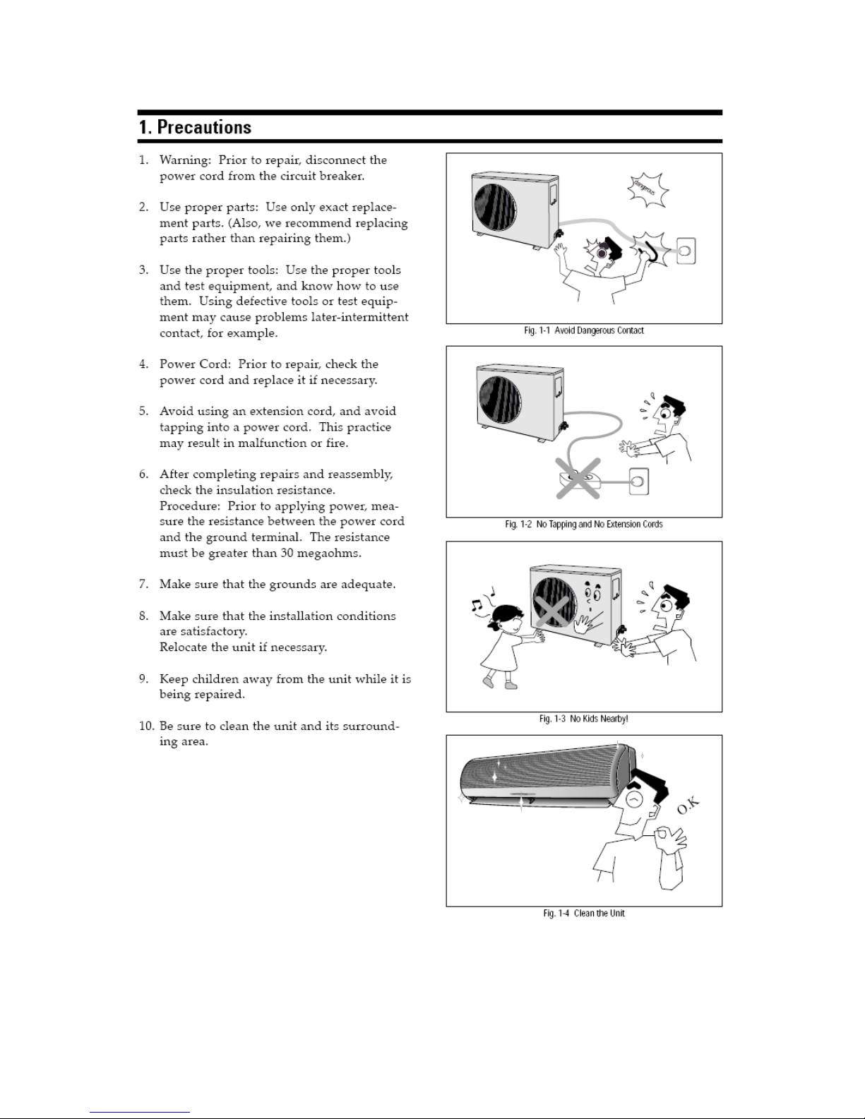
— 1 —
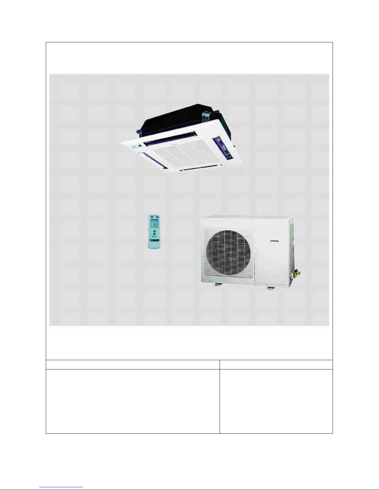
Introduction and Features
Model Remarks
GE AIR C18 (Communication Seat-and-Ceiling Mounted Unit)
1PH 230V 50Hz R407C
1
Page 5
— 2 —
Model Remarks
GE AIR C24(Communication Ceiling Mounted Unit) 1PH 230V 50Hz R407C
Page 6

— 3 —
Model Remarks
GE AIR C34 (Communication Ceiling Mounted Unit)
GE AIR C41 (Communication Ceiling Mounted Unit)
3PH 380V 50Hz R407C
Page 7

— 4 —
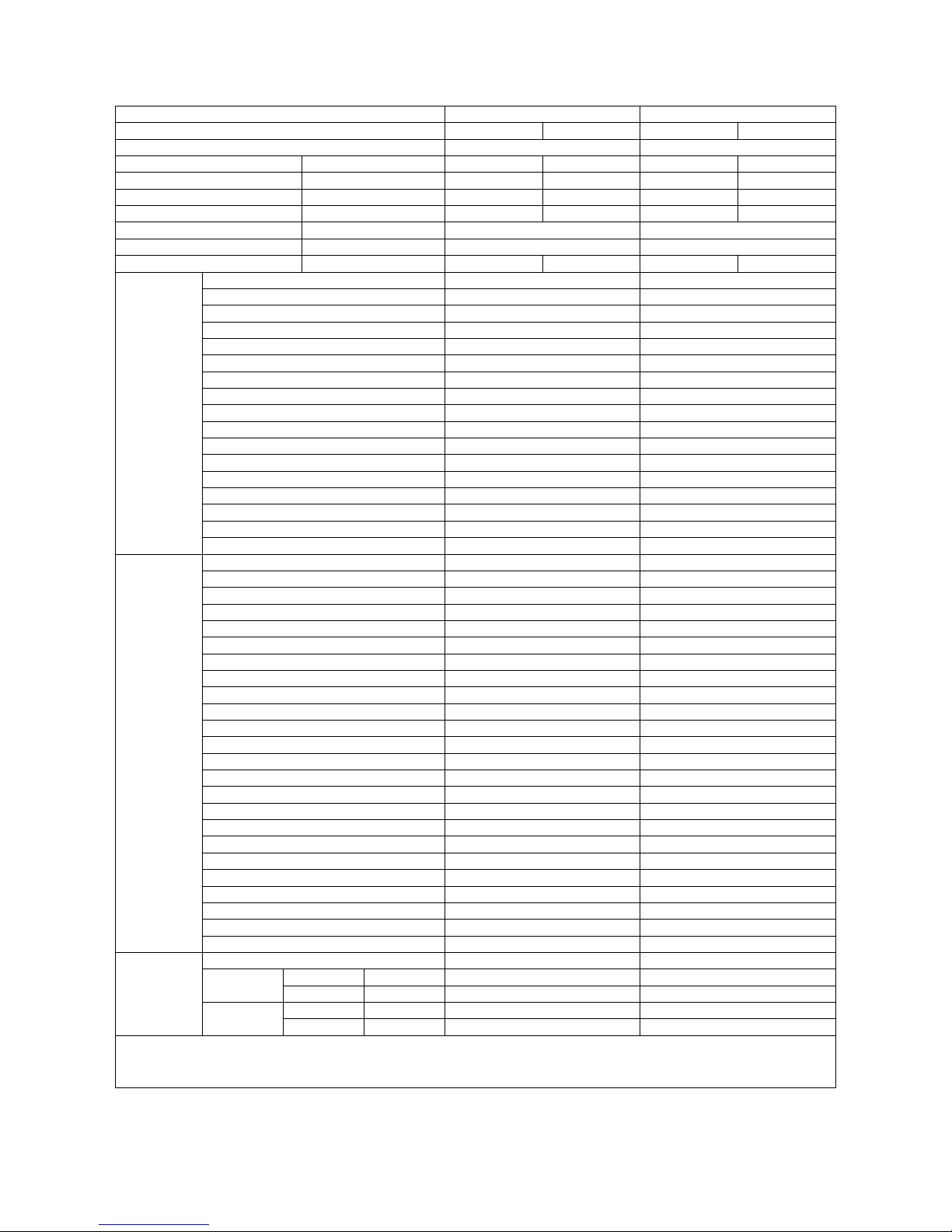
Specifications and Technical Parameters
Model GE AIR C18 GE AIR C24
Function Cooling Heating Cooling Heating
Power (Phase-Frequency-Voltage) 1Ph 50Hz 230V 1Ph 50Hz 230V
Total Capacity (W) 5000 5500 7000 7500
Nominal Power (W) 2150 3200 3200
Rated power (W) 10 2250 4032 3863
Rated current (A) 5000 9.5 19.75 19.18
Air flow volume (m3/h) 680 1180
Dehumidify volume (L/h) 2.9 4
C.O.P/EER (W/W) 2.325 2.444 2.19 2.34
Model GE AIR C18 IN GE AIR C24 IN
Fan motor speed(r/min)(H/M/L) 820/720/620 600/550/500
Output power of motor(W) 11 35
Fan Motor Capacitor 2.5 3.5
Fan type-piece Centrifugal Fan—1 Centrifugal Fan—1
Diameter-length(mm) φ283-148 φ450X140.5
Evaporator Aluminum fin-copper tube Aluminum fin-copper tube
Pipe diameter φ9.52 φ7
Row-fin distance (mm) 2-1.5 2-1.5
Extended area of heat exchange (I×H×L) 0.203 0. 301
Swing motor model MP35EA SM008
Power of motor (W) 4 3
Fuse (A) PCB3.15A Transformer 0.2A PCB3.15A Transformer 0.2A
Sound (pressure level) dB(A) 47.8/44.7/40.4 46.2/44.3/41.8
Dimension W/D/H)(mm) 600X600X230 840X840X240
Dimension of package (W/D/H)(mm) 848X678X310 970X970X310
Indoor unit
Net weight/gross weight (kg) 20/27 30/38
Model GE AIR C18 OUT GE AIR C24 OUT
Compressor Model CHW33TC4-U C-RN220H5B
Compressor Type Rotary Type Rotary Type
LRA(A) 71/75/78
Compressor Overload Protector Type Internal Inherent Protector Internal Inherent Protector
Throttle Method Capillary Capillary
Starting Method Capacitor Capacitor
Range of working temperature (℃) -7℃≤T≤43℃ -7℃≤T≤43℃
Condenser Aluminum fin-copper tube Aluminum fin-copper tube
Pipe diameter φ9.52 Φ9.52
Row-fin distance (mm) 2-1.8 2-1.8
Extended area of heat exchange (I×H×L) 0.308 0.589
Fan motor speed(rpm) 780/620/380 780/600/460
Output power of motor(W) 60 60
Operating capacitor(uF) 3 3
Air Flow Volume of Outdoor Unit 2700
Fan type-piece Axial Flow Fan—1 Axial Flow Fan—1
Fan Diameter(mm) Ф450 Ф450
Defrosting Method Auto Auto
Sound (pressure level) dB(A) ≤59 ≤60
Dimension W/D/H)(mm) 950X700X412 950X840X412
Dimension of package (W/D/H)(mm) 1100X755X450 1100X950X450
Net weight/gross weight (kg) 65/70 75/80
Outdoor
Unit
Refrigerant/Refrigerant Charge (kg) R407C/2.0 R407C / 2.8
Length 5 5
Liquid Pipe (mm) Φ9.52(3/8”) Φ9.52(3/8”)Outer
Diameter
Gas Pipe (mm) Φ16(5/8”) Φ16(5/8”)
Height (m) 5 5
Connecting
Pipe
Max.
Distance
Length (m) 10 10
2
Page 8
— 5 —
Model GE AIR C34 GE AIR C41
Function Cooling Heating Cooling Heating
Power (Phase-Frequency-Voltage) 3Ph 50Hz 380-400V 3Ph 50Hz 380V
Total Capacity (W) 10000 10500 12000 12500
Nominal Power (W) 4230 4335 4900 4800
Rated power (W) 5100 4600 6598 5900
Rated current (A) 9.7 9.2 12.08 10.53
Air flow volume (m3/h) 1860 1860
Dehumidify volume (L/h) 7 70
C.O.P/EER (W/W) 2.4 2.55 2.45 2.6
Model GE AIR C34 IN GE AIR C41 IN
Fan motor speed(r/min)(H/M/L) 610/560/510 710/660/610
Output power of motor (W) 50 60
Fan Motor Capacitor 4.5 4.5
Fan type-piece Centrifugal Fan—1 Centrifugal Fan—1
Diameter-length (mm) φ476X169.5 φ476X169.5
Evaporator Aluminum fin-copper tube Aluminum fin-copper tube
Pipe diameter Φ7 φ7
Row-fin distance (mm) 3-1.6 3-1.6
Extended area of heat exchange (I×H×L) 0.335 0.559
Swing motor model SM008 SM008
Power of motor (W) 3 3
Fuse (A) PCB3.15A Transformer 0.2A PCB3.15A Transformer 0.2A
Sound (pressure level) dB(A) ≤51.2/50.3/48.4 ≤54(50.4/47.8/46.3)
Dimension W/D/H)(mm) 840X840X320 840X840X320
Dimension of package (W/D/H)(mm) 970X970X394 970X970X394
Indoor unit
Net weight/gross weight (kg) 38/46 38/46
Model GE AIR C34 OUT GE AIR C41 OUT
Compressor Model C-SB303H8A C-SB263H3A
Compressor Type Rotary Type Rotary Type
LRA (A) 45 48
Compressor Overload Protector Type Internal Inherent Protector Internal Inherent Protector
Throttle Method Capillary Capillary
Starting Method Capacitor Capacitor
Range of working temperature (℃) -7℃≤T≤43℃ -7℃≤T≤43℃
Condenser Aluminum fin-copper tube Aluminum fin-copper tube
Pipe diameter φ9.52 Φ9.52
Row-fin distance (mm) 2-1.8 2-1.8
Extended area of heat exchange (I×H×L) 0.882 0.883
Fan motor speed (rpm) 840/ 740/640 840/350/200
Output power of motor (W) 68 60
Operating capacitor (uF) 3.5 3.5
Air Flow Volume of Outdoor Unit 4500 4500
Fan type-piece Axial Flow Fan—1 Axial Flow Fan—1
Fan Diameter (mm) Ф450 Ф450
Defrosting Method Auto Auto
Sound (pressure level) dB(A) ≤62 ≤62
Dimension W/D/H)(mm) 950X1240X412 950X1240X412
Dimension of package (W/D/H)(mm) 1110X1295X450 1100X1295X450
Net weight/gross weight (kg) 112/123 112/123
Outdoor Unit
Refrigerant/Refrigerant Charge (kg) R407C/3.4 R407C/3.8
Length 5 5
Liquid Pipe (mm) Φ12 Φ12 Outer
Diameter
Gas Pipe (mm) Φ19 Φ19
Height (m) 5 5
Connecting
Pipe
Max.
Distance
Length (m) 10 10
Parameter data of specifications in the form are subject to change without prior notice. Refer to
the actual data specified on the nameplate of the unit.
Page 9
— 6 —
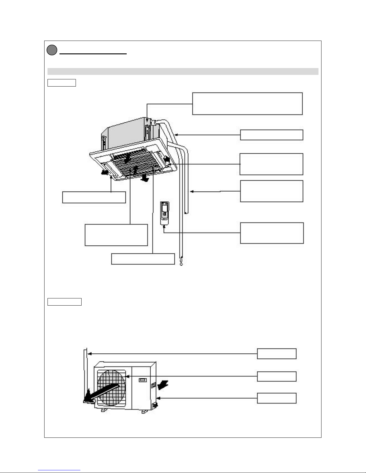
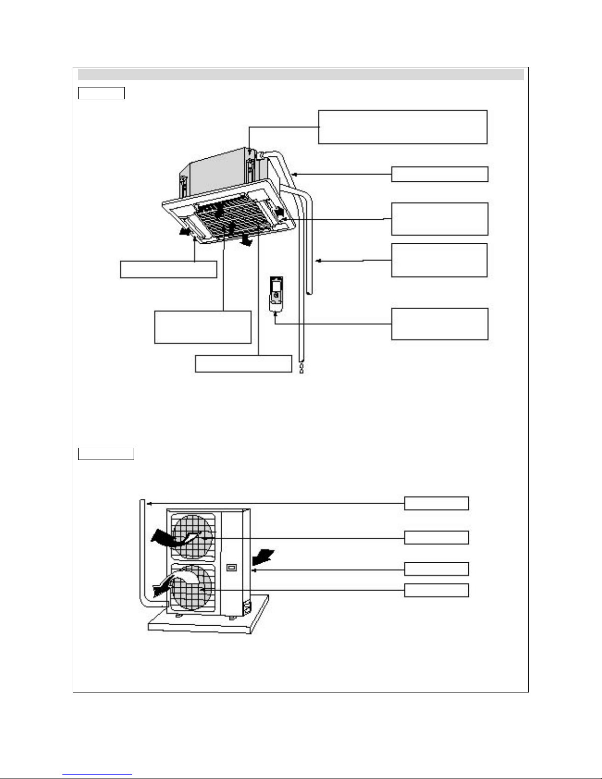
Component Name
Applicable to GE AIR C18 & C24
Indoor unit
Outdoor Unit
3
The drainage device (built-in type) will
discharge condensing water out of the unit
under cooling mode.
Air filter, air cleaner
(
within air inlet grill)
Air
outlet
A
ir inlet grill
Drainage pipe
Guide louver
(within air outlet)
Connecting pipe
Remote controller
Connecting pipe
A
ir outlet
A
ir inlet
Page 10
— 7 —
Applicable to GE AIR C34 & C41
Indoor unit
Outdoor Unit
The drainage device (built-in type) will
discharge condensing water out of the unit
under cooling mode.
Air filter, air cleaner
(
within air inlet grill)
A
ir outlet
A
ir inlet grill
Drainage pipe
Guide louver
(within air outlet)
Connecting pipe
Remote controller
Connecting pipe
A
ir outlet
A
ir inlet
A
ir outlet
Page 11

— 8 —
Overall and Installing Dimension
4.1 Overall and Installing Dimension of Indoor Unit
Applicable to GE AIR C18 IN
Overall dimension
Installing dimension
Over 1500MM Over 1500MM
Floor
4
Over 1800MM
Page 12

— 9 —
Applicable to GE AIR C24, C34 and C41 IN
Overall dimension
Installing dimension
Over 1500MM Over 1500MM
Floor
Over 1800MM
Page 13

— 10 —
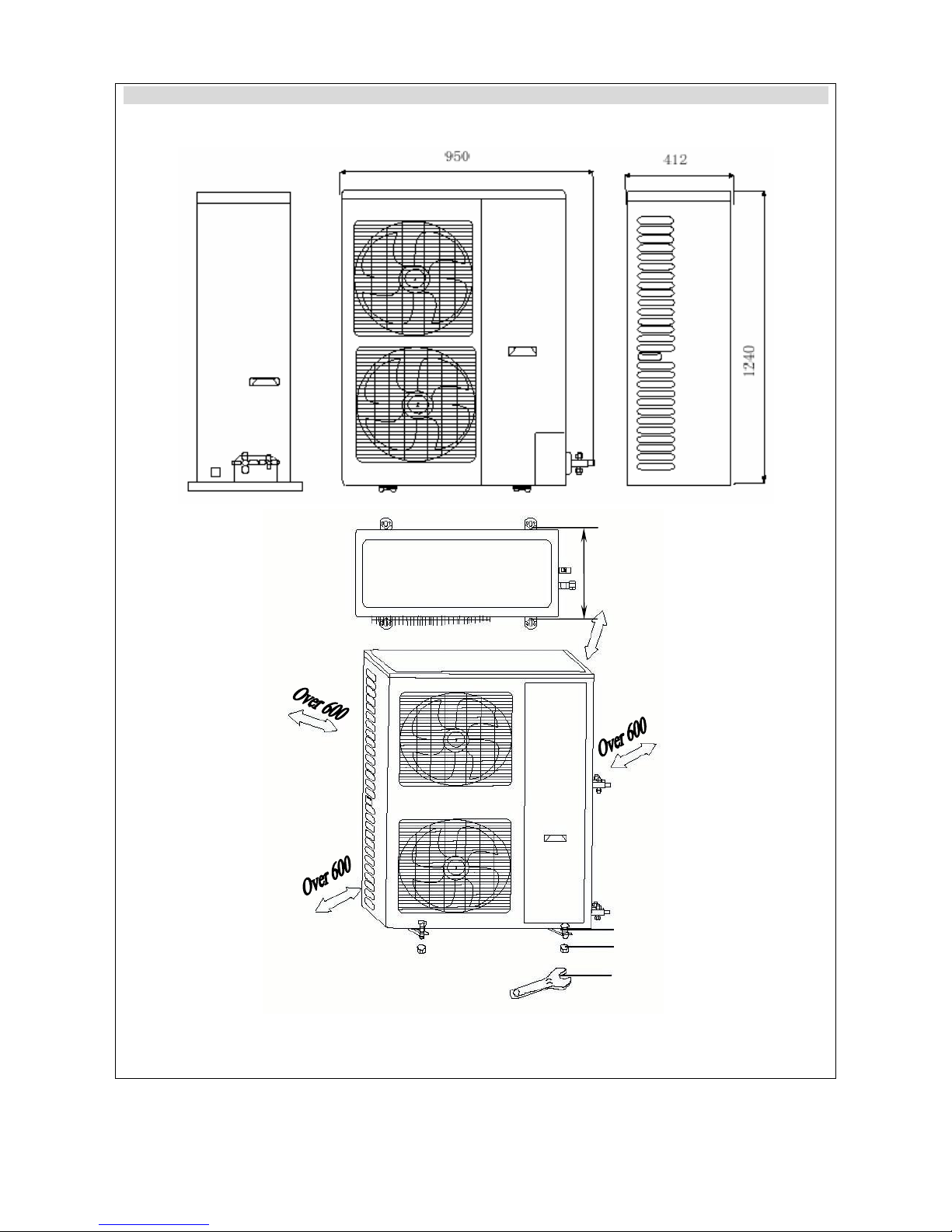
4.2 Overall and Installing Dimension of Outdoor Unit
Applicable to GE AIR C18 OUT
Unit: mm
Over 600
Bolt
Nut
Wrench
Page 14

— 11 —
Applicable to GE AIR C24 OUT
Unit: mm
Over 600
Bolt
Nut
Wrench
Page 15
— 12 —
Applicable to GE AIR C34 & C41 OUT
378
Unit: mm
Over 600
Bolt
Nut
Wrench
Page 16

— 13 —
System Diagram
5.1 System Diagram for Cooling-and-Heating Unit
Capillary
4-way valve
Evaporator Condenser
Cooling
Gas-liquid separator
Heating
Compressor
Switch on the power to start the unit. Low-pressure refrigerant vapor from evaporator is absorbed into
the compressor, where it is compressed into high-temp. and high-pressure gas. The gas refrigerant is
then diverted to condenser, where it is liquidized after heat exchange with outdoor air. After that, the
liquidized refrigerant flows through capillary for decrease of temperature and pressure and then enters
into evaporator, where it becomes low-temp. and low-pressure refrigerant vapor after heat exchange
with indoor air to be regulated. This process is repeated in cycle to achieve the purpose of cooling.
(Under heating mode, the 4-way valve will change the flow of refrigerant, so that the condenser absorbs
heats and the evaporator gives out heats, thus to achieve the purpose of heating).
5
Page 17

— 14 —
Electrical Diagram
GE AIR C18
GE AIR C24
6
Page 18

— 15 —
GE AIR C34
GE AIR C41
In case of any change in the Electrical Diagram shown above, please follow the drawing on cabinet.
Page 19

— 16 —
Controller and Remote Controller Function Manual and Operating Instructions
7.1 Controller and Remote Controller Function Manual 1
7.1.1 Temperature Parameters
◆Indoor preset temperature (T
preset
) ◆Indoor ambient temperature (T
amb.
) ◆Outdoor condenser temperature (T
cond.
)
7.1.2 Basic Functions
Under any mode, the compressor will keep running within 6 minutes once it is started (except under overfull protection).
Once stopped, it cannot be restarted until after 3-minute delay. When outdoor fan is started, run at high speed for 8
seconds and then switch to desired speed.
7.1.2.1 Cooling Mode
7.1.2.1.1 Cooling Conditions and Process
When T
amb.
≥ T
preset
+1℃, the unit will run under cooling mode, in which case the compressor and outdoor fan will be
started and the indoor fan will run at low speed.
When T
amb≤Tpreset
-1℃, the unit will be stopped under cooling mode, in which case the compressor and outdoor fan will
be stopped and the indoor fan will run at preset speed.
When T
preset
-1℃<T
amb.
< T
preset
+1℃, the unit will maintain its original operating status.
¾ Under this mode, the switchover valve will be de-energized and the temperature can be set within a range from 16 to
30℃.
7.1.2.2 Dehumidifying Mode
7.1.2.2.1 Working Conditions and Process of Dehumidifying
When T
amb.
> T
preset
+2℃, the unit will run under cooling mode, in which case the compressor and outdoor fan will be
started and the indoor fan will run at low speed.
When T
preset
-2℃≤T
amb.≤Tpreset
+2℃, the compressor, indoor unit and outdoor fan will run 6 minutes and stop 4 minutes
in repeated cycle, while the indoor fan will run at low speed.
When T
amb.
< T
preset
-2℃, the compressor, outdoor fan and indoor fan will be stopped.
¾
Under dehumidifying mode, the temperature can be set within a range from 16 to 30℃.
7
T
amb
T
preset
+1℃
T
preset
-1℃
Start cooling
Original operating status
Stop cooling
6 min.
Preset speed
Run
Stop
6 min.
3 min.
T
amb
T
preset
+2℃
T
preset
-2℃
Cooling
Stop cooling
Run
Stop
Low speed
Dehumidifying
Compressor
Indoor fan
Outdoor fan
Compressor
Indoor fan
Outdoor fan
6 min.
6 min.
4 min.
4 min.
Page 20

— 17 —
Auto Speed
Low Speed
Medium Speed
High Speed
7.1.2.3 Heating Mode
7.1.2.3.1 Heating Conditions and Process
When T
amb.≤Tpreset
+1℃, the unit will run under heating mode, in which case the valve, compressor, outdoor fan and
indoor fan will run at preset speed under preset cold air prevention conditions.
If T
amb.≥Tpreset
+3℃, the compressor and outdoor fan will be stopped, the valve is still energized and the indoor fan will
run at low speed.
When T
preset
+1℃<T
amb.
< T
preset
+3℃, the unit will maintain its original operating status.
¾ Under heating mode, the temperature can be set from 16 to 30℃.
¾ If the unit is switched off under heating mode or switched from heating mode to another mode, the 4-way valve will
be de-energized 2 minutes after the compressor is stopped.
7.1.2.3.2 Defrosting Conditions and Process
When the condenser is detected to have frost, the system will enter into defrosting status and the guide louver will be
adjusted to level position. The auxiliary heater (if any) will be stopped firstly. After 1-minute lag, the compressor, indoor fan
and outdoor fan will be stopped. After 3 seconds, the 4-way valve will be closed. Thirty seconds after the 4- way valve is
closed, the compressor will be started and the defrosting begin. Upon completion of defrosting, the compressor will be
stopped and the 4-way valve will be energized. After 30 sec onds, the compressor and ou tdoor fan will be started and t he
indoor fan will run under cold air prevention mode.
7.1.2.3.3 Liquid Splash Protection
1. When the unit is put into heating mode for the first time or it is switched to heating mode from another mode, the
4-way valve will be energized and the indoor fan will run under cold air prevention mode 20 seconds after the
compressor and outdoor fan are started. If the unit is switched off under heating mode or switched from heating
mode to another mode, the 4-way valve will be de-energized 2 minutes after the compressor is stopped.
2. When the compressor is started for the first time, the exhaust temperature protection will be shielded for 1 minute.
7.1.2.3.4 Cold Air Prevention Condition
The indoor unit will firstly adjust the guide louver to level, while the indoor fan will run at low speed.
1. When up to UNIT ON temperature, the compressor will be started, the indoor unit will run at low speed and the guide
louver will remain at level position. After 30 seconds, the indoor unit will be switched to preset fan speed and the
guide louver will run as preset.
2. When lower than UNIT ON temperature, the guide louver will remain at level position and the indoor unit will run at
low speed.
7.1.2.4 Fan Mode
Indoor fan will run at preset speed
The temperature can be set within a range from 16 to 30℃.
7.1.2.5 Auto Mode
Under this mode, the system will automatically select the run mode (cooling, dehumidif ying, heating and fan) depending
on the ambient temperature. Protection function is the same as under cooling and heating mode.
Thirty-second delay is provided for switching between different modes. (Every 30 seconds the system will detect if to
switch the mode).
T
preset
+3℃
T
preset
+1℃
T
amb
Start cooling
Stop cooling
Maintain original
operating status
Compress
Run
Stop
Preset speed
Preset speed
Low speed
≥6 min.
≥3 min.
≥6 min.
Indoor fan
Outdoor fan
Switchover valve
Page 21

— 18 —
7.1.3 AUTO ON/OFF and Sleep
71.3.1 AUTO ON/OFF
◆ AUTO ON
When the timer is set to ON, the system will be under AUTO OFF status. At the time for AUTO ON, the controller will
remain under its preset mode. The time interval for AUTO ON or OFF is 0.5h, and can be set within 0.5 - 24 hours.
◆ AUTO OFF
You can set AUTO OFF function when the unit is under ON status. Upon the time of AUTO OFF< the system will be
switched off. The time interval for AUTO OFF is 0.5h, and can be set within 0.5 - 24 hours.
7.1.3.2 Sleep
If the controller is under cooling or dehumidifying mode, th e preset temperature will be increased b y 1℃ one hour
after running under sleep mode, and increased by another 1℃ after 2 hours. Totally 2℃ will increas ed in 2 hours.
After that, the unit will run at this temperature.
If the controller is under heating mode, the preset temperature will be decreased by 1℃ one hour after running
under sleep mode and will be decreased by another 1℃ after two hours. The temperature will decreased by 2℃
within two hours. After that, the unit will run at this temperature.
No sleep function under fan mode or auto mode.
7.1.4 Other control
7.1.4.1 Indicator Control
7.1.4.1.1 Indoor Unit Indicator
1. The Run Indicator (red) will be bright when the unit is started and be black when the unit is stopped.
The Run Indicator will blink under one of following conditions upon start of the unit:
Definition of Faults and
Protection
Display of Run Indicator Notes:
System High-pressure
Protection
Black for 3 seconds and
blink once
Indoor Antifreeze
Protection
Black for 3 seconds and
blink 2 times
System Low-pressure
Protection
Black for 3 seconds and
blink 3 times
Compressor Air-out
Protection
Black for 3 seconds and
blink 4times
Communication Fault
Run Indicator
Black for 3 seconds and
blink 6times
The Run
Indicator will
blink under
one of
following
conditions
upon start of
the unit:
2. AUTO ON/OFF Indicator (yellow): It is bright under AUTO ON/OFF or Sleep mode; otherwise it is black.
The AUTO ON/OFF indicator will blink under one of following conditions upon start of the unit:
T
preset
T
preset
+1℃
T
preset
+2℃
T
preset
1 hours
2 hours Over 2 hours
1 hours
2 hours Over 2 hours
T
preset
T
preset
-1℃
T
preset
-2℃
T
preset
Page 22

— 19 —
Definition of Faults and
Protection
Display of Run Indicator Notes:
Defrost
Black for 3 seconds and
blink once
Overfull protection
Run Indicator
Black for 3 seconds and
blink 8 times
The Run Indicator
will blink under
one of following
conditions upon
start of the unit:
3. Compressor indicator (green): Bright when the compressor is started; black when the compressor is stopped.
4. Communication Run Indicator (Indoor unit panel LED1 – green)
The communication indicator will blink if the communication is normal.
7.1.4.1.2 Outdoor Unit Indicator
1. Upon energization, D120 will blink for several times and then changed to Normal Bright status.
2.D119 will blink when the communication is normal.
3. D120 will blink in case of fault on any of outdoor sensor (outdoor ambient sensor, outdoor tube sensor, air-out temperature sensor).
4.D118, D119 and D120 will blink simultaneously when the communication is abnormal.
7.1.4.1 Swing Control
You can control its ON and OFF by using the handset swing key.
7.1.4.2 Buzzer Control
When the controller receives valid key-press signal upon energization, the buzzer will give out a beep.
7.1.4.3 Automatic Control of Indoor Fan Speed
Under this mode, the indoor fan will automatically select high, medium or low speed depending on ambient temperature. Thirty-second
delay is provided for switching of fan speed.
7.1.4.4 Air Exchange
The air exchange motor will be started by remote control of Air Exchange 1 or Air Exchange 2 when the indoor fan is in normal operation.
The air exchange motor will be stopped if remote control of air exchange is cancelled or indoor fan is stopped.
7.1.5 Protection
7.1.5.1 Indoor Antifreeze Protection
If evaporator temperature is equal to or lower than -4℃ five minutes after the compressor is started under cooling or dehumidifying
mode, the Run Indicator will blink, the compressor and outdoor fan will be stopped, the indoor fan and swing motor will maintain their
original status, and the water pump will be started. When the compressor has been stopped for 10 minutes and the evaporator
temperature is equal to or higher than 15℃, the indicator will be black and the controller will run under preset mode.
The key is not shielded under antifreeze protection.
7.1.5.2 Compressor High-pressure Protection
When high-pressure protection is detected, any other loads expect the water pump will be turned off, all key-press and remote control
signals will be shielded, and the Run Indicator will blink. When compressor is detected free of high-pressure protection, shield function
will be cancelled and the Run Indicator will blink. To restore the operation, it is required to press ON/OFF key to switch off the unit and
indicator before pressing ON/OFF key again.
7.1.5.3 Compressor Low-pressure Protection
1. After the compressor is started, if it is detected for several minutes successively that the low-pressure switch is disconnected, the
complete unit will be stopped and the Run Indicator will blink. After 3 minutes, the unit will restore automatically. If low-pressure
switch protection occurs 2 times successively, the Run Indicator will blink and the unit cannot restore automatically, so as to remind
the user of air leakage. Press ON/OFF key to switch off the unit and press it again to restore operation.
2. Low pressure switch signal will not be detected under defrost. Detection will start 10 minutes after completion of defrost.
3. From the controller, you can press down compulsive key and auto key simultaneously to shield the detection of low pressure switch
signal for purpose of air collection. Detection will resume automatically after 6 minutes, or you can resume detection by pressing
ON/OFF key to switch off the unit and pressing it again to start the unit.
4. If outdoor temperature is equal to or lower than 0℃ under heating mode, detection of low pressure switch will be shielded.
5. If the compressor is running while outdoor fan is stopped (high-temp. protection) under heating mode, detection of low pressure
switch will be shielded. Detection of low pressure switch signal will start after outdoor fan resumes operation.
6. When the compressor is stopped, if it is detected for several minutes successively that the low-pressure switch is disconnected, the
complete unit will be stopped and the Run Indicator will blink, in which case the unit cannot restore automatically. You can press
ON/OFF key to switch off the unit and press this key again to restore operation.
7.1.5.4 Exhaust Pipe High Temp. Protection (No detection of exhaust pipe high temp. protection under defrost)
After the compressor is started, if it is detected that the exhaust temperature is too high or that the exhaust temp. sensor has fault 30
seconds successively, the Run Indicator will blink. The unit will be stopped when the indoor ambient temperature reaches the preset
value.
After the compressor has been stopped for 3 minutes, if the exhaust temperature keeps lower than 90℃ for 3 seconds successively, the
complete unit will restore operation. If the above protection occurs 2 times successively, the complete unit cannot restore operation and
the Run Indicator will blink.
Page 23

— 20 —
Y ou have to press ON/OFF key to switch off the unit and then press this key again before you can make the unit run under
preset mode, provided that the exhaust temperature is lower than <90℃. Otherwise, the Run Indicator will keep blinking.
7.1.5.5 Indoor Over temperature Protection
If it is detected that the evaporator temperature (T
evap.
)is equal to or higher than 56℃ under heating mode, the outdoor fan
will be stopped. If the evaporator temperature is equal to or lower than 51℃, the outdoor fan will be started. If the
evaporator temperature is equal to or higher than 100℃, the indoor fan will automatically switch to high speed. If the
evaporator temperature is equal to or lower than 48℃, the indoor fan will switch to original preset speed.
7.1.5.6 Water Pump Control and Overfull Protection
1. When compressor is started under cooling or dehumidifying mode, the water pump must be started simultaneously.
2. When switching off the unit, or stopping the unit under cooling mode, or stopping unit under dehumidifying mod e, or
switching the unit to another mode, the water pump will be de-energized after 5-minute lag.
3. When overfull is detected no matter under any mode, the water pump must be started.
4. When overfull is detected within 8 seconds successively under ON status or compulsive cooling or compulsive
heating, the unit will enter into overfull protection status and the AUTO ON/OFF indicator will blink. The outdoor fan
and compressor will be stopped under cooling mode or compulsiv e cooling, and th e indoor fan will be stopped after
1-minute delay. All controls will be disconnected under dehumidifying mode. If switching off all other loads except the
4-way valve under heating mode or compulsive heating, the indoor fan will be stoppe d after 1-minute delay. Under
fan mode, the indoor fan will be stopped after 1-minute delay.
5. When it is detected under overfull protection that the overfull signal disappears, the water pump shall be immediately
stopped if it has worked for 10 minutes. If the water pump is working for less than 10 minutes, it will continue until up
to 10 minutes before it is de-energized.
6. After Overfull Signal Disappears and press ON/OFF key to switch off the unit, you can press this key a gain to start
the unit and exit the protection. If the overfull signal does not disappear within 2 hours, the water pump will be
stopped.
7.1.5.7 Communication Fault
If no data are received within 3 minutes successively, the outdoor unit will stop compressor and outdoor fan, while the
4-way valve will be closed 2 minutes after the compressor is stopped. The indoor unit will stop all other load except the
water pump.
7.1.5.8 Key
1. Test Key:
Pressing this key under OFF status, the unit will be compulsively put into cooling mode, all other loads except the 4-way
valve will be started, and the indoor and outdoor fan will run at high speed. If holding down this key for 1 second or longer
under OFF status, the unit will enter into compulsive heating mode, all loads will be started and the indoor and outdoor fan
will run at high speed. If it is detected that ambient temperature (or evaporator temperature) is equal to or lower than -10
℃, or that ambient temperature (or evaporator temperature) is equal to or higher than 80℃, the buzzer will beep. When
pressing the key or receiving remote signal for exit of test status, or after 5 minutes, the unit will exit the test status. Under
testing status, all other protection except communication fault, high-pressure protection and overfull p rotection will be
disabled. The complete unit will be stopped if you press this key u nder ON status. The cooling-only unit is not provid ed
with compulsive heating function.
2. AUTO Key
The unit will run under auto mode if you press this key un der OFF mode. The complete unit will be stopped if you press
this key under ON status.
7.1.5.9 Power-OFF Memory Function
Memory mode, swing, preset temperature, preset fan speed, Auto ON/OFF (When the ti mer counts the time again after
the power is cut off and then resumed before preset AUTO OFF time, the unit, if de-energized and r e-energized after
preset AUTO OFF time, will run under such mode as after preset AUTO OFF time). If the unit is ON before power is off,
the compressor will have 3-minute protection.
Page 24

— 21 —
7.2 Description and Function of Remote Controller Keys
Notes:
z Make sure that there is no obstruction between remote controller and signal receiving window.
z Do not fall off or throw the remote controller.
z Do not let any liquid flow into remote controller, or expose the remote controller under direct sunshine or extreme hot
temperature.
SWING key
One press of this key will enable
the guide louver to swing at a
specific angle. Another press
will stop the guide louver.
TEMP. key
Each press of (+) key will
increase the preset temperature
by 1℃. Each press of (-) key will
decrease the preset
temperature by 1℃.
Under “ “ mode,
the indoor temperature can be
adjusted to any value between
16~30℃.
MODE key
The run mode will change
sequentially as below with
each press of MODE key.
A
uto
FAN key
Each press of this key will
change the fan speed
sequentially as below:
Note: The fan speed is not
adjustable under “ “ mode.
Cooling mode
Dehumidifying mode
Fan mode
Heating Mode
ON/OFF key
Press this key to start the ai
r
conditioner. Press it again to
stop the air conditioner.
Page 25

— 22 —
7.3 Description and Function of Remote Controller Keys (After opening the front cover)
Note: This remote controller is for general use and applicable to multiple types (functions) of air conditioner.
Air, humid, light, anion, and save button are not used in this remote control.
LCD display
Display the information selected
by each key
SLEEP key
Press this key to enter into sleep mode
and press it again to exit sleep mode.
Note: There is no sleep function unde
r
A
uto or Fan mode.
A
UTO OFF key
Pressing this key when the unit
is running, you can set the
A
UTO OFF time from 0 to 24
hours.
Cancel the
AUTO ON/OFF
A
UTO ON key
Pressing this key when the unit is stopped,
you can set the AUTO ON time from 0 to 24
hours. Each press of this key will increase
the time by 0.5 hour.
Cancel the
AUTO ON/OFF
Page 26

— 23 —
7.4 Installation of Remote Controller Battery
z Op erating Guideline
General Procedures:
1. Switch on the power and press ON/OFF key to start the air conditioner.
2. Press MODE key to select your desired run mode.
3. Press SWING key to enable the guide louver to swing at a specific angle. Press it again to stop the swing.
4. Press FAN key to set the fan speed.
5. Press +/- key to set your desired temperature.
Optional Procedures:
6. Press SLEEP key from remote controller to set the sleep mode.
7. Press AUTO ON/OFF key and then press +/- key to set the timer.
Note: When auto mode is selected, the air conditioner will automatically select an appropriate run mode according to the
indoor temperature, making the environment comfortable.
z Replacement of Remote Controller Battery
Two pieces of 7# alkali dry batteries are used in the remote controller.
1. Slide the battery cover of remote controller downward. Remove the old batteries and r eplace with two pieces of ne w
batteries (Take care that the polarity shall be correct)
2. Close the battery cover of remote controller.
Note:
z Do not use new batteries together with
old batteries, or use different types of
batteries together.
z To avoid leakage of liquid and damage
to the remote controller, please take
out the batteries if you will not use the
remote controller in several weeks.
z Operate the remote controller within
effective range.
z Keep the remote controller at least 1
meter away from television set or
sound equipment.
Battery cover
RESET key
Insert two 7# batteries.
Page 27

— 24 —
Disassembly and Assembly Procedures
8.1 Disassembly Procedures of Indoor Unit
Operating Procedures / Photos Applicable Unit Models: GE AIR C18 IN
Disassemble Front Grill
Manually push the clasp of front grill sub-assy downward to open the
front grill. (refer to Figure 8-1)
Disassemble Front Panel
Manually unplug the socket connector of the guide louver motor
cable and the limit switch cable. Use screwdriver to twist off four
screws and Disassemble the front panel. (refer t o Figure 8-2)
Disassemble Water Tray
Manually unplug the socket connector of motor cable. Use
screwdriver to screw off the screw fixing the temp. sensor and
the motor cable. Push the water level switch cable, water
pump cable and temp. sensor cable aside. Use screwdriver to
screw off the four screws and pull the water tray upward to
remove the water tray. (refer to Figure 8-3)
8
Left Clasp
Right
Figure 8-1
Screw
Figure 8-2
Water Tray
Temp.
Sensor
Screw
Figure 8-3
Page 28

— 25 —
Operating Procedures / Photos
Disassemble Electric Box, Control Panel and Fan
Use screwdriver to screw off the two screws to remove the electric
box cover.
Use screwdriver to screw off the two screws to remove the electric
box.
Use spanner to turn and loose the nut with washer. Manually pull the
fan upward to remove it. (refer to Figure 8-4, 8-5 and 8-6)
Disassemble Motor and Evaporator
Use screwdriver to screw off the two screws beside the isolation
plate and then screw off the eight screws to remove the motor.
Use screwdriver to screw off the two screws of the connection board
of evaporator. Screw off the two screws at the tube-exit plate.
Use screwdriver to screw off the screw at the support of evaporator,
disassemble the support of evaporator, and then manually pull the
evaporator assy to remove it. (refer to Figure 8-7, 8-8 and 8-9)
Figure 8-4
Screw
Figure 8-5
Figure 8-6
Nut with Washer
Figure 8-7
Screw
Screw
Nut with Washer
Figure 8-8
Screw
Figure 8-9
Page 29

— 26 —
Operating Procedures / Photos
Disassemble Pump Drainage Pipe
Use wire cutter to cut the cable bundle, separate the pump drainage pipe and the pump water outlet, use
screwdriver to screw off the two screws beside the drainage pipe, then pull the pump drainage pipe
outward to remove it. (refer to Figure 8-10 and 8-11)
Disassemble Pump Assy,
Pump and Water Level Switch
Use socket wrench to twist off the nut beside
the pump assy, and then manually pull the
pump assy upward to remove it.
Use screwdriver to screw off the four screws
beside the pump.
Use screwdriver to screw off the two screws
beside the water level switch. (refer to Figure
8-12, 8-13 and 8-14)
Liquid Level Switch
Pump
Pump Drainage Pipe
Figure 8-10
Screw
Figure 8-11
Nut with Washer
Figure 8-12
Screw
Pump
Screw
Water Level
Switch
Screw
Figure 8-13
Figure 8-14
Page 30

— 27 —
Operating Procedures / Photos
Disassemble Filter, corner Inner Cover
and Stepping Motor
Screw off the screws and pull out the filter.
Use screwdriver to screw off the screws and remove
the angle inner cover.
Screw off the screw beside the stepping motor, turn
the stepping motor to a certain angle and then remove
the stepping motor. (refer to Figure 8-15, 8-16 and
8-17)
Disassemble Guide Louver
Lift the connecting rod and manually separate it from
the universal joint. Use screwdriver to unscrew the
connecting screws. (refer to Figure 8-18)
Filter
Screw
Figure 8-15
Screw
Figure 8-16
Stepping Motor
Screw
Figure 8-17
Universal Joint
Connecting Rod
Figure 8-18
Page 31

— 28 —
8.2 Disassembly Procedures of Indoor Unit
Operating Procedures / Photos Applicable Unit Models: GE AIR C24, C34, C41 IN
Disassemble Front Grill Sub-Assy
Push the left and right clasps of the front grill to
the center and lift them at the same time. After
the front grill is in the 45°angle position, pull it
backward. (refer to Figure 8-1)
Disassemble Front Panel
Manually unplug the connection joints of guide
louver motor cable and the limit switch cable. At
the left clasp, use screw driver to twist off the
screw of electric box cover Ⅱ, Disassemble the
electric box cover Ⅱand then unplug the 6-core
cable plug. At the left clasp, manually pull the
four corner outer covers outward to remove
them. Use screwdriver to screw off the four
screws, turn the front panel anticlockwise, and
then pull it upward to remove it. (refer to Figure
8-2, 8-3 and 8-4)
Disassemble Water Tray
Manually unplug the socket connector of motor
cable. Use screwdriver to screw off the screw
fixing the temp. sensor and the motor cable.
Push the water level switch cable, water pump
cable and temp. sensor cable aside. Use
screwdriver to screw off the four screws and pull
the water tray upward to remove the water tray.
(refer to Figure 8-5, 8-6 and 8-7)
Figure 8-5
Left Clasp
Right Clasp
Figure 8-1
6-core cable
plug
Electric Box
Cover II
Electric Box
Cover I
Figure 8-2
Figure 8-3
Figure 8-4
Corner Outer Cover
Screw
Electric Box Cover I
Screw
Page 32

— 29 —
Operating Procedures / Photos
Disassemble Electric Box, Control Panel and
Fan
Use screwdriver to screw off the two screws to remove
the electric box cover.
Manually push the two clasps, and pull the control
panel upward to remove it.
Use spanner to turn and loose the nut with washer.
Manually pull the fan upward to remove it.
(refer to Figure 8-8, 8-9 and 8-10)
Grounding Wire
Temp. Sensor Cable
Water Level Switch Cable
Water pump cable
Socket Connector o
f
Stepping Motor Cable
Water Tray
Screw
Figure 8-6
Figure 8-7
Figure 8-8
Clasp
Screw
Nut with Washer
Figure 8-9
Figure 8-10
Page 33

— 30 —
Operating Procedures / Photos
Disassemble Motor and Evaporator
Use screwdriver to screw off the two screws
beside the isolation plate and then screw off
the eight screws to remove the motor.
Use screwdriver to screw off the two screws of
the connection board of evaporator. Screw off
the two screws at the tube-exit plate.
Use screwdriver to screw off the screw at the
support of evaporator, disassemble the
support of evaporator, and then manually pull
the evaporator assy to remove it. (refer to
Figure 8-11)
Disassemble Air Outlet Rear Side
Plate Sub-assy
First remove the velvet sheet and the left and
right side plate cushions at the air outlet; then
use screwdriver to screw off the screw shown
in the figure. (refer to Figure 8-14 and 8-15)
Screw
Screw
Screw
Figure 8-11
Figure 8-12
Screw
Figure 8-13
Liquid Level Switch
Pump
Cable Bundle
Pump Drainage
Pipe
Screw
Figure 8-14
Figure 8-15
Page 34

— 31 —
Operating Procedures / Photos
Disassemble Pump Assy,
Pump and Water Level Switch
Use socket wrench to twist off the three nuts
beside the pump assy , and then manually pull
the pump assy upward to remove it.
Use screwdriver to screw off the four screws
beside the pump.
Use screwdriver to screw off the two screws
beside the water level switch.
(refer to Figure 8-16 , 8-17 and 8-18)
Disassemble Filter, Angle
Inner Cover and Stepping Motor
Push the two clasps inward, pull the filter
backward, Use screwdriver to screw off the
eight screws at the corner inner cover, and
remove the corner inner cover. Use
screwdriver to screw off the two screws
beside the stepping motor to remove the
stepping motor. Remove the filter.
(refer to Figure 8-19 , 8-20 and 8-21)
Figure 8-16
Pump
Water Level Switch
Screw
Figure 8-17
Figure 8-18
Screw
Filter
Clasp
Figure 8-19
Screw
Figure 8-20
screw
Page 35

— 32 —
Operating Procedures / Photos
Disassemble Guide Louver and
Panel Controller
Lift the connecting rod and manually separate it
from the universal joint. Use screwdriver to
unscrew the connecting screws.
Use screwdriver to unscrew the screw beside the
receiving window. Pull forward and then lift the
receiving window cover to remove it. Push the two
clasps to remove the panel controller.
(refer to Figure 8-22 , 8-23 and 8-24)
Stepping Motor
Screw
Figure 8-21
Universal Joint
Connecting Rod
Figure 8-22
Receiving Window Cover
Screw
Figure 8-23
Clasp
Panel
Controller
Figure 8-24
Page 36

— 33 —
8.3 Disassembly Procedures of Outdoor Unit
Operating Procedures / Photos Applicable Unit models: GE AIR C18, C24 OUT
Disassemble Front Side Plate
Screw off the four screws around the front side plate
to remove the front side plate.
(refer to Figure 8-25)
Disassemble Top Cover
Screw off the tapping screws around the top cover,
and then pull the top cover upward to remove it.
(refer to Figure 8-26)
Disassemble Rear Grill
Screw off the four screws around the rear grill to
remove the rear grill.
(refer to Figure 8-27)
Figure 8-25
Figure 8-26
Figure 8-27
Page 37

— 34 —
Operating Procedures / Photos
Disassemble Housing
Use screwdriver to screw off the screws around the
housing to remove the cabinet.
(refer to Figure 8-28)
Disassemble Electric Box
Use screwdriver to screw off the screws fixing the
electric box, and pull the electric box to remove it.
(refer to Figure 8-29)
Disassemble Right Side Plate
Use screwdriver to screw off the screws at the right
side plat, condenser side plate, gas valve and liquid
valve, and then pull the right side plate sub-assy
upward to remove it.
Screw
Cabinet
Figure 8-28
Screw
Electric Box
Communication Ceiling
Type Unit Electric Box
Screw
Figure 8-29
Screw
Right Side Plate
Figure 8-30
Page 38

— 35 —
Operating Procedures / Photos
Disassemble Axial Flow Fan
Use spanner to remove the nut at the fan to
remove the axial flow fan.
(refer to Figure 8-31)
Disassemble Outdoor Motor
Screw off the four tapping screws fixing the
motor, pull out the motor lead-out cable plug, and
remove the motor. Screw off the two tapping
screws fixing the motor support, and pull the
motor support upward to remove it.
(refer to Figure 8-32)
Disassemble 4-Way Valve
Screw off the holding nut of the 4-way valve coil
and remove the coil. Use wet cotton cloth to wrap
the 4-way valve, unsolder the four soldering
points connecting the 4-way valve, and remove
the 4-way valve. Be quick during the unsoldering
process, pay attention to keep the wrapping cloth
wet and do not allow the soldering flame to burn
the compressor lead-out cable.
(refer to Figure 8-33)
Screw
A
xial Flow Fan
Figure 8-31
Motor
Screw Fixing
the Motor
Motor Cable
Motor Support
Fixing Screw
Figure 8-32
4-Way Valve
Soldering Point
Figure 8-33
Page 39

— 36 —
Operating Procedures / Photos
Disassemble Capillary
Unsolder the soldering points at the capillary, the valve
and the condenser to remove the capillary. Pay attention
not to allow the soldering slag to block the capillary.
(refer to Figure 8-34)
Disassemble Valve
Unscrew the two screws fixing the gas valve, unsolder the
soldering point between the gas valve and the return-air
duct and remove the gas valve.
(Note: when unsoldering the soldering point, use wet cloth
to completely wrap the gas valve to prevent valve body
from being harmed by high temperature).
Unscrew the two screws fixing the liquid valve, unsolder
the soldering point connecting the liquid valve and the fork
type pipe, and remove the liquid valve.
(refer to Figure 8-35)
Disassemble Compressor
Firstly unsolder the pipes connecting the compressor, and
then unscrew the three foot nuts at the compressor to
remove the compressor.
(refer to Figure 8-36)
Capillary
Figure 8-34
Liquid Valve
Screw
Gas Valve
Figure 8-35
Foot Nut
Figure 8-36
Page 40

— 37 —
8.4 Disassembly Procedures of Outdoor Unit
Operating Procedures / Photos Applicable Unit models: GE AIR C34, C41 OUT
Disassemble Rear Grill
Screw off the tapping screws at the rear side plate, valve
support chassis and condenser side plate to remove the
rear grill. (refer to Figure 8-62)
Disassemble Top Cover Plate
Screw off the tapping screws around the top cover, and
then pull the top cover upward to remove it.
(refer to Figure 8-37)
Disassemble Front Side Plate
Screw off the three tapping screws at the front side
plate, and then pull the front side plate upward to
remove it.
(refer to Figure 8-38)
Page 41

— 38 —
Operating Procedures / Photos
Disassemble housing
Unscrew the screws around the
housing to remove it.
(refer to Figure 8-39)
Disassemble Electric Box
Unscrew the screws around the
electric box sub-assy to remove the electric
box sub-assy.
(refer to Figure 8-40)
Disassemble Right Side Plate
Unscrew the screws around the
right side plate to remove it.
(refer to Figure 8-41)
Screw
Cabinet
Figure 8-39
Screw
Screw
Communication Cassette
Type Unit Electric Box
Figure 8-40
Screw
Right Side Plate
Figure 8-41
Page 42

— 39 —
Operating Procedures / Photos
Disassemble Axial Flow Fan
Use spanner to remove the nut at the fan to remove the
axial flow fan.
(refer to Figure 8-42)
Disassemble Outdoor Motor
Screw off the four tapping screws fixing the motor, pull
out the motor lead-out cable plug, and remove the motor.
Screw off the two tapping screws fixing the motor
support, and pull the motor support upward to remove it.
(refer to Figure 8-43)
Disassemble 4-Way Valve
Screw off the holding nut of the 4-way valve coil and
remove the coil. Use wet cotton cloth to wrap the 4-way
valve, unsold the four soldering points connecting the
4-way valve, and remove the 4-way valve. Be quick
during the unsoldering process, pay attention to keep the
wrapping cloth wet and do not allow the soldering flame
to burn the compressor lead-out cable.
(refer to Figure 8-44)
Screw
Screw
Figure 8-42
Motor
Screw Fixing
the Motor
Motor Support
Fixing Screw
Figure 8-43
4-Way Valve
Figure 8-44
Page 43

— 40 —
Operating Procedures / Photos
Disassemble Valve
Unscrew the screw fixing the valve, unsolder the connecting
pipe of the valve, and remove the valve. (refer to Figure
8-45)
Disassemble Capillary
Unsolder the soldering points between the capillary and
other pipes to remove the capillary. (refer to Figure 8-46)
Disassemble Compressor
Unscrew the foot screw of the compressor and unsolder the
connecting pipe to remover the compressor. (refer to Figure
8-47)
Screw
Liquid
Valve
Gas
Valve
Screw
Figure 8-45
Capillary
Figure 8-46
Foot Nut
Figure 8-47
Page 44

— 41 —
Care and Maintenance
Warning
z Be sure to stop the unit and plug off the power before cleaning your
air conditioner. Otherwise, electric shock may happen.
z Don’t splash water on indoor unit, it may cause the risk of electric
shock.
z Volatile liquids such as thinner or gasoline will cause damage to the
appearance of air conditioner. (Only use soft dry cloth or wet cloth soaked with neutral detergent to
clean the indoor unit).
10.1 Clean the front panel
① Clean the front panel
Clean the surface of front panel with soft wet cloth and then gently wipe it with dry cloth.
② Remove front grill
Use your hand to push the left and right clamp on front
grill to the middle. At the same time, lift them up to
form 45℃ angle. Pull the front grill backward to
remove it.
③ Clean the front grill
Clean the surface of front panel with soft wet cloth and
then gently wipe it with dry cloth.
④ Install the front grill
Use your hand to put the front grill into front case at an
angle of 45℃, making the front hook jointed to the
groove of front case. Then, use your hand to push the
left and right clamp on front grill to the middle. Close
the front grill.
10.2 Clean the air filter
① Remove the air filter
From the grooves on two ends of the front panel, pull
the front panel open to an angle along the arrow direction. Then, pull the
air filter downward to remove it, as shown on right.
② Clean the air filter
Clean the filter with vacuum cleaner. If the filter is too dirty, wash with
warm water (below 45℃) that is added with neutral detergent. Then dry it
at a cool place, as shown on right.
③ Install the air filter
Push the air filter into the groove of front grill. Use your hand to push the
two clamps inward and close the filter.
Notes:
Never expose the front grill or air filter directly under the sun. Never clean
it with hot water over 45℃ or dry it on fire, (as this will cause decoloring,
fire or deformation).
9
Page 45

— 42 —
above 1500
above 1500
above 1500
Unit : mm
Floor
Figure 1
above 500
above 500
above 300
above 2000
Unit : mm
Floor
Figure 2
above 2000
above 1000
above 1000
Obstacles
Installation Instructions
11.1 Installation Dimension Drawing
① Indoor Unit
Model H
GE AIR C18 230
GE AIR C24 240
GE AIR C34 320
GE AIR C41 320
② Outdoor Unit
10
Obstacles above
Page 46

— 43 —
11.2 Installation Dimension Drawing
① Selection of Installation Position
1. The air inlet and air outlet of the indoor unit must be far away from obstacles to ensure that airflo w can reach every
corner of the room;
2. Ensure the installation of indoor unit is in conformity with the requirements of installation dimension dra wing;
3. Choose a place where four times of the weight of indoor unit can be withstood and operating noise an d vibration are
not increased;
4. The installation position must been horizontal;
5. Choose a position where condensation water can be easily d ischarged and the air-con ditio ning water system can be
easily connected;
6. Ensure sufficient clearance and space for service and maintenance; Ensure the unit is at least 1800cm from the floor;
7. Use suspending bolts for the installation. Check if the installation position can withstand four times the weight of the
unit. In case it is not the case, reinforce the installation position before installing the unit (refer to the installation paper
mould to find out the points to be reinforced).
Caution :
1. Ensure the cooking smoke extractor abov e the gas stove has
enough capacity of extracting smoke, so that the smoke is not
suctioned by the air-conditioning unit.
2. Ensure the air-conditioning unit is far away from the kitchen, so
that cooking smoke is not suctioned by the air-conditioning unit.
② Dimensions of Ceiling Opening and Position of Suspending Bolt(M10)
Caution :
The dimension of the ceiling opening marked with * can be as long as 910mm, but the length of the overlapp ing part
between the ceiling and the decorative from panel shall be at least 20mm.
Keep enough
clearance
With enough exhaust capacity
Cooking Smoke Extractor
Gas Stove
950 Decorative Front Panel
890* Ceiling Opening
840 Unit
780 Clearance between Suspending Bolts
Refrigerant Pipe
Suspending Bolts (×4)
680 Clearance between
Suspending Bolts
840 Unit
890 Ceiling Opening
950 Decorative Front Panel
Body Installation Frame
Ceiling
A
Direction
20 mm
Page 47

— 44 —
③ Ceiling Mount of Unit Body
1. Initial Installation of Indoor Unit
● Attach the suspending frame base to the suspending bolt. Nuts and washers must be used at the upper and
lower sides of the suspending frame base to secure it. The locating plate⑦ can prevent the washer from falling
off.
● Refer to the installation paper mould ⑤ for the dimensions of the ceiling opening.
● The installation paper mould marks the center of the ceiling opening.
● The label of the unit and the installation paper mould all mark the center of unit.
● Use screw⑥ (3 pieces) to install the installation paper mould⑤ to the unit and use screws to fix the angle of the
drainage groove at the outlet of the pipe.
2. Adjust the position of the unit so that it is in the correct installation position (refer to Figure 3)
3. Check if the unit is horizontal
● The indoor unit is equipped with built-in draining pump and l evel tube
● In case the unit inclines toward the direction opposite the flow direction of condensate water, the float switch
may suffer from failure, so that dripping is caused.
4. Remove the washer locating plate⑦ for preventing the washer from falling off. Tighten the nut on it.
5. Remove the installation paper mould.
Warning : Please tighten the nuts and bolts to prevent them from dropping.
Nuts (provided by user on site)
Washer③(accessory)
Suspending Frame Base
Tightening (Double Nuts)
(Secure the suspending frame base)
Inserting In
Locating Plate of Washer ⑦ (accessory)
(Secure the washer)
Level Tube
Polyethylene pipe
Center of Ceiling Opening
Screw ⑥ (accessory)
The screw beside the pipe outlet is secured
at the corner of the drainage groove
Installation Paper Mould ⑤
Screw ⑥ (accessory)
(Secure the Installation Paper Mould)
Page 48

— 45 —
④ Connection of Refrigerant Pipe
● When connecting the pipe to the unit or disassemble the pipe from the unit, use the spanner and the torque
spanner at the same time as shown in the figure.
● Refer to Table 1 for the torque needed for tightening the conical nut.
● Apply refrigerant oil in and outside the conical nut during the connection. First manually screw 3 to 4 circles, and
then use the torque spanner to tighten it.
● Refer to table 1 to decide the tightening torque (excess tightening may damage the nut so as to cause leakage).
● Check if the connecting pipe has leakage, and then carry out thermal insulation as shown in the figure.
● Only use middle sponge (11) to wrap the joint part between the gas pipe and the insulating sleeve⑧ of the
collect gas pipe.
Table 1 :
Pipe
Dia.
Wall
Thickness
(mm)
Tightening
Torque
Explanation
φ9.52 ≥0.71 30~40N.m
φ16 ≥1 40~50N.m
φ12 ≥1 60~65N.m
φ19 ≥1 70~75N.m
The allowed maximum design length of connecting pipe of
air-conditioning unit is 25m (15m for 50 Series0。In case the
pipe is longer than 10m, add the following amount of
refrigerant for each extra meter :
GE AIR C18 Add 30g
GE AIR C24 Add 40g
GE AIR C34 Add 40g
GE AIR C41 Add 50g
A
pply refrigerant oil here
Middle Sponge (Accessory) (11)
(Use gasket to wrap the pipeline joint)
Torque Spanner
Cable Bundle ④(×4)
Spanner
Pipeline Joint
Conical Nut
Insulating Sleeve of
Liquid-entered Pipe ⑨
(
For Liquid Pipe
)
Insulating Sleeve of
Collect Gas Pipe ⑧
(
For Air Pipe
)
Collect Gas Pipe
Liquid-entered Pipe
Page 49

— 46 —
⑤ Drainage Pipe
1 Installing Drainage Pipe
● The diameter of drainage pipe shall be equal to or larger than the diameter of the connecting pipe (size of
polyethylene pipe : outer diameter 25mm, wall ≥①1.5mm)
● The draina ge pipe shall be short, with a declining slop as at least 1/100, so as to avoid the forming of gaseous
envelope.
● In case it is impossible to h ave enough slope for the flexible drainage pipe, install a drainage lift pipe.
● To avoid bending of the flexible drainage pipe, the distance between the two suspenders shall be 1 to 1.5m.
(Correct) Slope more than 1/100 (Wrong)
● Use the flexibl e drainage pipe ①and the clamp ② supplied as accessories with the unit
● Insert the flexible draina ge pipe into the drainage faucet, and then tighten the clamp ②.
● Use the big sp onge⑩ to wrap the clamp at the flexible drainage clamp for thermal insulation.
● Take thermal insulation measures for the indoor flexible drainage pipe.
2 Precautions for Installing Drainage Lift Pipe
● The installation height of drainage lift pipe shall be less than 280mm.
● The drainage lift pipe shall be perpendicular to the unit and no more than 300mm from the unit.
Note : The gradient of accessory flexible dr ainage pipe ① shall be within 75mm, so that the drainage faucet does not
subject to extra external force.
ST-Joint Confluent Drainage Pipe
Above 100mm
3. After installation is completed, check if the water can be drained smoothly.
● Fill in 600cc water from the outlet or the check hole slowly to check the draining conditions.
● After the electrical lines are installed, check the draining conditions in the cooling operation.
Clamp ②
Sponge (Gray)
Flexible Drainage Pipe①
Big Sponge⑩ (Accessory)
Clamp② (Accessory)
Below 4mm
Roof
Within 300
Suspending Frame Base
Below 280mm
Flexible Drainage
Tube ①(accessory)
Drainage Lift Pipe
Ceiling
Clamp② (accessory)
Page 50

— 47 —
● Method of filling water
Draining Outlet for Service Purpose (with Rubber Plug)
(This outlet is only for discharging the water inside the
drainage groove)
⑥ Electrical Line Layout
● All supplied components, materials and electrical operation must be in conformity with the local laws and regulations.
● The power supply must be of rated voltage of the unit and special electrical line for air-conditioning.
● For electrical operati on, refer to the“Electrical Dia gram ”attached on the unit.
● All installation of electric lines must be carried out by professional electricians.
● A circuit breaker must be installed for the purpose of cutting off the power supply of the whole system when needed.
● Grounding measures must be taken.
● Carry out installation in acc ordance with the state line layout rules.
Drainage Pipe
Cover Plate of
Check Hole
Check Hole
above 100mm
Plastic Spray Can
(The pipe shall be around
100mm long)
(Fill water from the air outlet side)
Page 51

— 48 —
⑦ Connecting Unit Cables
● Open the cove r of the electric box (1), pu ll in the power connectin g cable through the r ubber bushing A, and use the
wire-pressed clamp to press them together.
● Carry out line connections according to the electrical diagram for the indoor side.
● After the connection is completed, secure the wire-pressed clamp.
● Connect the cable of the controller.
Open the cover of the electric box (2), pull in the signal control cable through the rubber bushing, and connect the
cable with the terminal of the controller.
● Use the small spon ge to wrap the cable (it is necessary to prevent condensation).
● After the connection is com pleted, use wire-pressed clamp to press it an d then install back the covers (1) (2) of the
electric box.
● Heating and Cooling Type Unit : Connect the 6-core rubber covered cable to the corresponding terminals of the 6-bit
terminal board.
Caution : When connecting the connection cables of the outdoor unit, the corresponding poles shall be connected
together.
3-Phase
Single Phase
(Cooling OR Heat
Pump Type)
4-Core Rubber
Covered Cable
(Electric Boosting Type)
6-Core Rubber Covered Cable
4-Core Rubber Covered Cable
Wire-Pressed Clamp
Wire-Pressed Clamp
Cable-Cross Block
Electric Box Cover (2)
Electric Box Cover (1)
Cable-Cross Loop
This position must be sealed to prevent
water from entering.
Page 52

— 49 —
⑧ Installing Front Panel
1. As shown in Figure 4, align the position of the guide louver motor at the front panel with the position of the pipe outlet
of the indoor unit.
2. Installing Front Panel
① Install the front panel to the indoor unit temporarily. When installing, hang the clasp on the hook of the indoor unit
opposite the position of the guide louver motor at the front panel (two positions).
② Temporarily hang the remaining two clasps on the main hook (pay attention not to entangle the cable of the guide
louver motor in the sealing materials).
③ Drive the four hexagon screws belo w the clasp in about 15 mm (The front panel shall ascend).
④ As shown in the figure, adjust the front panel to the direction of the arrow, so that the adjusting plate engages with
the ceiling well.
⑤ Tighten the screws until the thickness of the sealing materials between the front panel and the indoor unit is
decreased to 5-8mm.
(Figure 4)
Clasp
Hook
Pipe Opening Position
Guide Louver Motor
Indoor Unit
Ceiling
Sealing Materials
5mm to 8mm
A
ir Outlet
Decorative Front Panel
Page 53

— 50 —
⑧ Precautions :
1. Improper tightness of the screw may cause the failure as shown in Figure 5.
Air Leakage
Air Leakage at Ceiling
Water Condensation Water Dripping
(Figure 5)
2. In case there is still split between the ceiling and the decorative front panel after the screws are installed, adjust the
height of the unit again. (refer to Figure 6.)
3. Lines of Decorative Front Panel (refer to Figure 7)
z Carry out connections for the two terminals of the guide louver motor cable located at the front panel.
If the ascending and descending range of the indoor
unit and the drainage pipe allow, adjust the height of the
indoor unit via the hole in the corner of the front panel.
Split is not allowed
At the Unit
Body
At the Front
At the Unit
Body
At the Front
(Figure 6)
(Figure 7)
Page 54

— 51 —
11.3 Installing Outdoor Unit
① Installing Outdoor Unit
1. Selection of Installation Position of Outdoor Unit
z A place where noise and airflow generated by air exhaust do not affect the neighbors;
z Cho ose a p lace with good ventilation to ensure good ventilation of outdoor unit;
z No obstacles near the outdoor unit obstructin g the air intake and air e xhaust of the unit;
z The installation position shal l be able to withstand the weight and vibration of the outdoor unit and ensure safe
installation;
z A place without the leakage of any flammable gases or corrosive gases;
z Do not allow strong airflow to blow the air outlet of the outdoor unit; if so, the fan may suffer from insufficient airflow
thus failure may occur.
z Do not install the unit in a place where there is machine oil, sulphur gas or high noise.
Attention : Enough space must be left above the outdoor unit to allow the unit to produce the best effect.
2. Installing Outdoor Unit
z If the outdoor unit is installed on steady floor such as concrete, use M10 screws and nuts to secure the unit and
ensure the unit is installed vertically and horizontally (refer to the figure for the positions of bolt holes).
z Do not install the unit on the roof of a building.
z In the event of noise owing to vibration, insert rubber cushion between the outdoor unit and the installation base.
z When the unit is under heating or defrosting operation, the outdoor shall carry out draining operation.
z If drainage pipe is to be installed, insert the drai nage join t (13) (accessory 1) into the drai nage hol e in the chassis of
the outdoor unit and then connect a drainage pipe to the drainage joint (if a drainage joint is to be used, the
installation height of the outdoor unit must be at least 5cm).
② Air Exhaust
1. Remove the nut cover at the shutoff valve.
2. Align with the center of the fitting pipe and manually tighten the conical nut sufficiently.
3. Use spanner to tighten the conical nut.
4. Remove the one way valve caps at the liquid valve and the gas valve.
5. Use inner hexagon spanner to twist off the liquid valve body and at the same time use screwdriver to open the valve
core of the one way valve. Now gas shall flow out.
6. After gas continues flowing out for about 15 second and refrigerant gas begins to flow out, close the one way valve
and tighten the valve cap.
7. Completely open the valve body of the liquid valve and the gas valve (Figure 9).
8. Turn and tighten the valve cap, then use soap water or a leak detector to check if there is gas leakage at the outdoor
and indoor units and the pipeline connections.
9. If conditions permit, use a vacuum pump to exhaust air in the unit from the one way valve (Figure 10).
Gas Pipe
Gas Valve
One Way Valve
Liquid Pipe
Liquid Valve
Screwdriver
Inner Hexagon Spanner
(Figure 8)
(Figure 9)
Page 55

— 52 —
Using Vacuum Pump
1. Connect the flexible charge tube of the manifold valve with the charge mouth of the low pressure valve (both the high
and low pressure valves must be closed).
2. Connect the flexible charge tube with the vacuum pump.
3. Put the low pressure (Lo) handle of the manifold valve to the complete open position.
4. Start the vacuum pump to operate vacuum pumping. Now open the connecting pipe nut of the lo w pressure valve
slightly to check if air is entering.
5. After the vacuum pumping is completed, put the low pressure (Lo) handle of the manifold valve to the complete close
position to stop the vacuum pump (after operating vacuum pumping for above 15 minutes, confirm if the reading of
multi-use meter is -10×105pa (-76cmHg)).
6. Completely open the high and low pressure valves.
7. Disconnect the flexible charge tube from the charge mouth of
the low pressure valve.
8. Tighten the low pressure valve cap (refer to Figure 10).
③ Electrical Cable Layout
1. Before connections, refer to the part voltages specified on the nameplate, and then carry out line connections
according to the electrical diagram attached on the unit. Do not connect high voltage cables with low voltage cables.
2. The air-conditioning unit must have special voltage cable and must be equipped with power leakage switch and air
switch so as to deal with the occurrence of overload.
3. The air-conditioning unit must be grounded to avoid harm as a result of insulation failure.
4. All lines must be corr ectly connected according to the electrical diagrams attached to the u nit. Wrong connections
may cause abnormal operation or damage of the air-conditioning unit.
Caution;
All electrical line layouts must be carried out by professional technicians. Wrong line layout may cause electric shock or
fire accident.
④Connection of Power Cables
1. Remove the front side plate (Figure 11).
2. Drill through the cable-cross hole at the outdoor unit and attach the cable-cr oss loop.
3. Pull all cables through the cable-cross loop hole.
4. Carry out line connections according to the electrical diagram for the outdoor unit side. Ensure the connections are
secure.
5. Use wire-pressed clamps to press and secure the cables.
Caution :
1. There must be reliable grounding.
2. The connections must be reliable.
3. The connection points shall not subject to tension.
4. Other cables must have reliable connections with their corresponding terminals.
5. For single phase, connect the two 3-core rubber covered cables to the corresponding terminals.
6. Cooling Only Type : (3-Phase)
Connect the 3-core rubber covered cable to the L, N1 terminals of the 8-bit terminal b oard. Connect the 5-core rubber
covered cable to the L1, L2, L3 and N terminals of the 8-bit terminal board.
Heating and Cooling Type : (3-Phase)
Connect the 5-core rubber covered cable to the 5-bit terminal board
Manifold Valve
Multi-Use Meter
-76cmHg
Lo Handle
Flexible Charge Tube
Pressure Gauge
Hi Handle
Flexible Charge Tube
Vacuum Valve
Low Pressure Valve
(Figure 10)
Page 56

— 53 —
⑤ Test Run
1. Preparation of Test Run
① Do not switch on the power before all installation work is completed.
② Confirm that the control line is correctly installed and all electrical lines are firmly connected.
③ Open the shutoff valves of the big and small pipes.
④ Remove all foreign articles, especially metal scraps, line ends and forceps, from the unit.
2. Method of Test Run
① Connect to the power supply, press the“ON/OFF”key to start test run.
② Press the Mode key, select the operating modes such as cooling and fan, and observe if the operation is normal.
3. Emergency Operation :
In case the remote controller is lost, carry out the following operation :
* When the unit is stopped, press the Auto switch on the corner outer coverⅡ, then the unit shall start auto operation. The
microprocessor shall automatically select cooling, heating or dehumidif ying accordi ng to the room temper ature to re ach a
comfortable effect.
* When the unit is in operation, press the Auto switch on the corner outer coverⅡ, then the unit stops operation (the
outdoor unit shall stop operation at the same time).
Caution :
The test switch on the corner outer coverⅡis specially for test run. When pressing this key, the air-conditioning unit carries
out compulsory running without subjecting to the limit of temperature.
Do not use this key when the air-conditioning unit is in normal operation!
Single Phase 3-Phase
Cooling Only Type
Heating and Cooling Type
3-Core Rubber Covered
Cable (Connecting to
Power Supply)
3-Core Rubber
Covered Cable
(Connecting to Room)
5-Core Rubber Covered
Cable (Connecting to
Electric Network Power
Source)
5-Core Rubber Covered
Cable (Connecting to
Indoor Unit)
5-Core Rubber Covered
Cable (Connecting to
Electric Network Power
Source)
Front Plate
Terminal Board
Rear Side Plate
Outdoor Cable-Cross Hole
Cable
(Connecting to Room)
(Connecting to Power Supply)
Electrical Connection Diagram of
Communication Cassette Type Unit
(Figure 11)
Page 57

— 54 —
Trouble-Shooting
Power cutoff
Restore power supply
Fuse burn-out Short-circuit between lines
Resolve the problem of short-circuit,
replace fuse
Resolve the problem of poor contact
Power plug is not firmly seated or
connection is poor
Plug is securely seated in the socket
Line connection failure between indoor unit
and outdoor unit
Check the line connection according
To the electrical diagram and ensure
correct connection
Controller fuse burned out
Replace controller fuse
No operation of both indoor and
outdoor units
Controller burned out
Replace controller
Indoor fan or motor burned out
or lines are disconnected
Repair or replace fan or motor
The switch is in
the air supply
mode but the
fan motor does
not run
Remote controller failure
Remove failure or replace damaged
parts
Coil line break
Both outdoor fan and
compressor do not run
Relay failure
Poor contact
Replace relay
Failure of outdoor fan motor
Replace relay
Failure of outdoor relay
Replace relay
The operation is under
“Cooling”or “Heating”
mode; the compressor
runs but the outdoor fan
does not run
Poor contact at defrosting temp.
sensor or at tube sensor
Replace defrosting temp. sensor or
tube sensor
Compressor failure
Replace Compressor
The operation is under
“Cooling”or “Heating”
mode; the outdoor unit
runs but the compressor
does not run
Operating capacitor of compressor
burned out
Replace capacitor
Cooling load is too heavy
Check the forecasted cooling load
Poor cooling effect
in cooling operation
Set temperature is too high
Decrease set temperature
11
Page 58

— 55 —
Outdoor unit is installed in an
improper position
Outdoor side shall have good ventilation
and install proper weather screen
Block in filter of indoor unit Periodically clean the filter
Block in outdoor heat exchanger
Wash away dust deposited on the
surface of heat exchanger
Fan speed is set too low Set the speed as high or medium
Leakage between internal high
pressure and low pressure
sections of compressor
Replace compressor
4-way valve failure Replace 4-way valve
Partial block in capillary Replace capillary
Pipeline valve is not fully opened Fully open the valve
Leakage of refrigerant
Find out leakage point and charge
refrigerant
Poor cooling
effect in cooling
operation
Poor thermal insulation of
refrigerant connecting pipe between
outdoor unit and indoor unit
Big pipe and small pipe shall have
separate thermal insulation
Heating load is too heavy Check the forecasted heating load
Set temperature is too low Increase set temperatur e
Mounting position of outdoor unit
is inappropriate
Outdoor side shall have good ventilation
Blockage of the filter of indoor unit Periodically clean the filter
Block in outdoor heat exchanger Rinse outdoor heat exchanger
Insufficient air passing through
the outdoor heat exchanger
Increase motor speed to set as high or
medium
Compressor failure Replace Compressor
4-way valve failure Replace 4-way valve
One way valve failure Replace one way valve
Poor heating
effect in heating
operation
Block in capillary Replace capillary
Page 59

— 56 —
Defrosting is incomplete Replace defrosting temp. sensor
Insufficient flow through pipeline valve Fully open the valve
Insufficient refrigerant Find out leakage point and charge refrigerant
Poor thermal insulation of refrigerant
connecting pipe between outdoor unit
and indoor unit
Big pipe and small pipe shall have separate
thermal insulation
Do not install it directly at steel window
Install it on thick wall with certain strength
Indoor unit is installed on wallboard or thin
wall panel so noise is caused owing to
resonance
Take proper vibration damping measures
Pipes of outdoor unit bump together Adjust fan motor position
Foreign articles inside the indoor unit Remove foreign articles
Vibration of compressor is violent
Adjust support foot mat of compressor, tighten
oose bolts
Pipes of outdoor unit bump together Separate bumping pipes
Tighten connection screws
Metal plates bump together inside the unit
Attach vibration damping gum between metal
plates
Indoor fan bumps cabinet Adjust fan position
Abnormal sound from inside compressor Replace Compressor
Abnormal electromagnetic noise from
4-way valve when in heating operation
Internal short circuit of solenoid valve, replace
solenoid valve
Abnormal sound and
vibration
Page 60

— 57 —
Trouble-Shooting
Air –conditioning unit
cannot be started
Trip of circuit
breaker or
burn-out of
f
use
When set short-circuiter
as“ON”, it trips
immediately
Check insulation resistance for
grounding; Confirm if
air-conditioning unit has electrical
-
When turning the air-conditioning unit
to the “ON”status, trip of circuit
breaker occurs several minutes late
r
Check circuit breaker,
measure resistance
for short-circuit
Both indoor
unit and
outdoor unit do
n
ot start
No power suppl
y
Check power supply status
Emission failure of remote controlle
r
Check remote controller
Serial communication failure between
indoor unit and outdoor unit
Winding protection function of
compressor is activated
Open circuit of sensor or moderation
function is activated
Failure of switch assembly unit
Poor cooling
Check if the set
temperature is
appropriate
Decrease upper
point set
temperature
Check if the cooling
load is appropriate
Check the
forecasted
cooling load
4-way value
failure
Replace
4-way valve
failure in flow
of refrigerant
Insufficient
refrigerant
Charge
refrigerant
Compressor
failure
Replace
Compressor
Insufficient flow
through pipeline
valve
Fully open
the valve
Block in air filte
r
Clean the
filter grill
Insufficient
air circulation
volume
Check if the fan
speed is set too
low
Set fan speed
as high or
medium
Poor thermal insulation of
refrigerant connecting pipe
between outdoor unit and
Big pipe and small
pipe shall have
separate thermal
insulation
Poor heating
Check if the set
temperature is
appropriate
Increase the set
temperature
Check if the heating
load is appropriate
Check the
forecasted
heating load
4-way value
failure
Replace
4-way valve
failure in flow
of refrigerant
Insufficient
refrigerant
Charge
refrigerant
Compressor
failure
Insufficient flow
through pipeline
valve
Fully open
the valve
Block in air filte
r
Clean the
filter grill
Small air
circulation
volume
Check if the fan
speed is set too
low
Increase fan
speed
Poor thermal insulation of
refrigerant connecting pipe
between outdoor unit and
Big pipe and small
pipe shall have
separate thermal
insulation
Replace
Compressor
 Loading...