

Page 1

g GE Consumer & Industrial Appliances
Service Manual & Installation Manual
Split System Air Conditioner
Model numbers:
PRO AIR 107
PRO AIR 109
PRO AIR 112
PRO AIR I109
PRO AIR I112
PRO AIR 218
GE AIR 326
GE AIR 428
Page 2

—1—
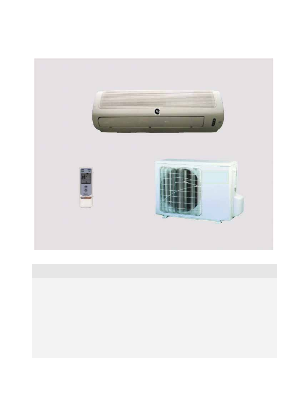
Summary and features
Model Remark
PRO AIR 107 IN / PRO AIR 107 OUT
1Ph 230V 50Hz R410A
1
Page 3
—2—
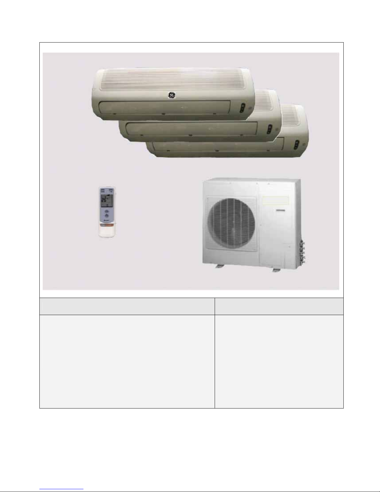
Model Remark
PRO AIR 109 IN / PRO AIR 109 OUT PRO AIR 112 IN / PRO AIR 112 OUT
PRO AIR I109 IN / PRO AIR I109 OUT PRO AIR I112 IN / PRO AIR I112 OUT
1Ph 230V 50Hz R410A
Page 4

—3—
Model Remark
PRO AIR 218 IN / PRO AIR 218 OUT
1Ph 230V 50Hz R410A
Page 5
—4—
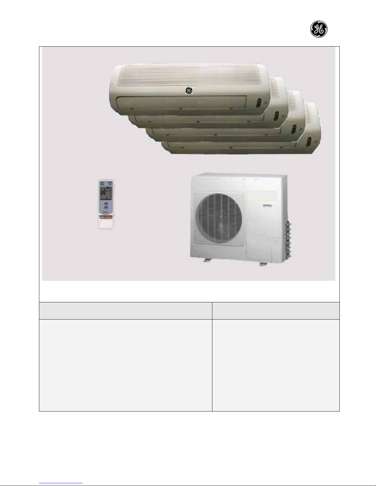
Model Remark
GE AIR 326 IN1 / GE AIR 326 IN2 / GE AIR 326 OUT
1Ph 230V 50Hz R407C
Page 6
—5—
Model Remark
GE AIR 428 IN / GE AIR 428 OUT
1Ph 230V 50Hz R407C
Page 7
—6—
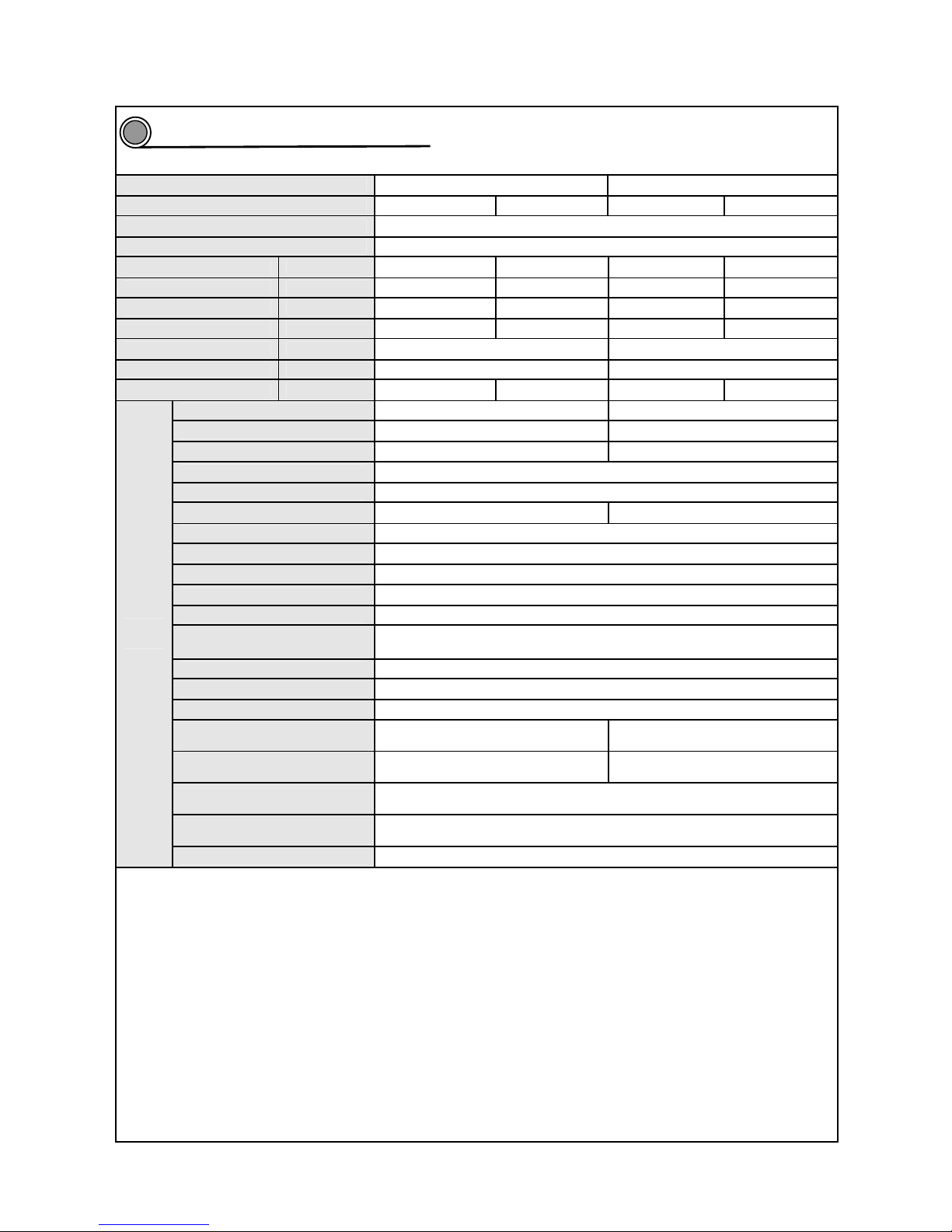
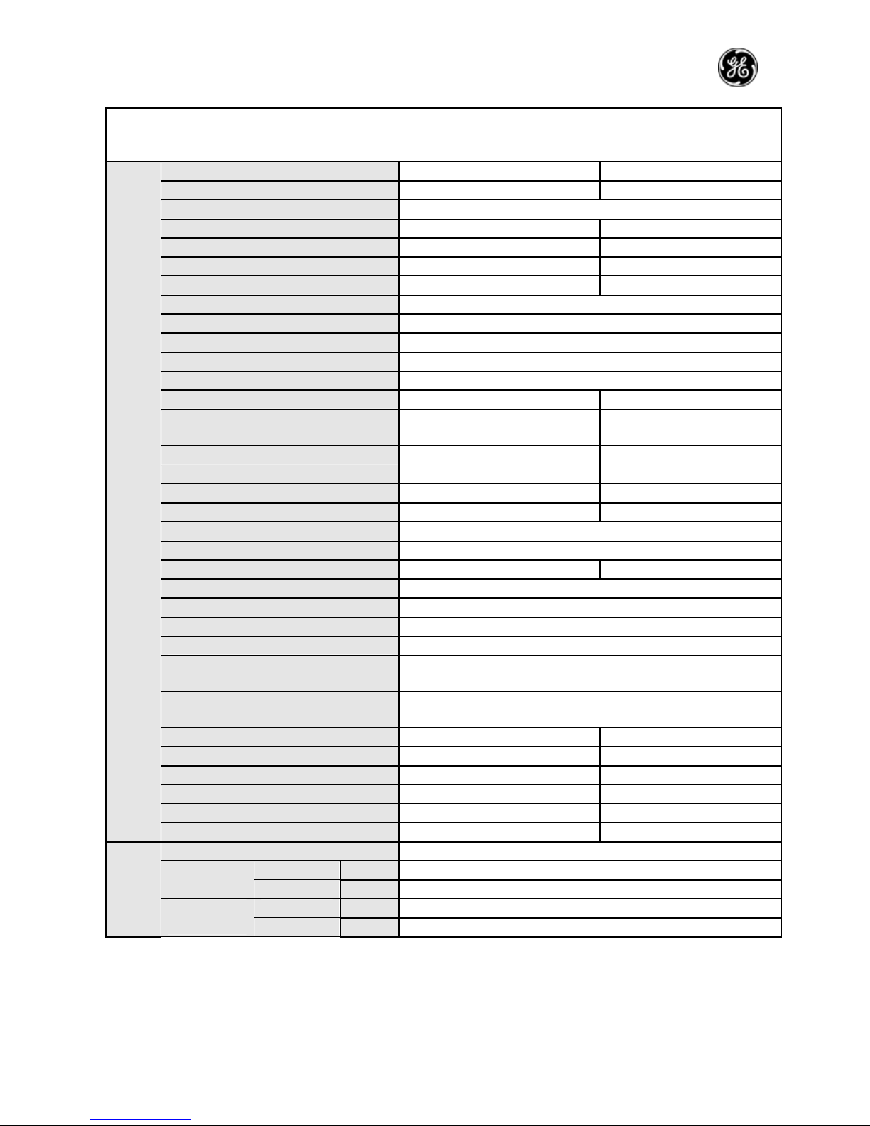
Technical and specifications
Model
PRO AIR 107 IN / PRO AIR 107 OUT PRO AIR 109 IN / PRO AIR 109 OUT
Function Cooling Heating Cooling Heating
Rated voltage 230V
Rated frequency 50Hz
Capacity (W) 2000 2200 2500 2600
Nominal power (W) 660 700 765 800
Max. power (W) 900 920 990 1050
Greatest currency (A) 4.1 4.3 4.8 5.5
Air flow (m3/h) 360 450
Dry capacity (L/h) 0.7 1.2
C.O.P/EER (W/W) 3.05 3.15 3.2 3.2
Model KFR-20G/NaA121-E KFR-25G/NaA121-E
Fan speed (r/min)(H/M/L) 1000/940/880 1160/1010/890
Output power (W) 8 14
Auxiliary electric heater power /
Fan capacitor 1
Fan motor running current 0.035 0.12
Fan type-piece
Axial flow fan-1
Diameter-length (mm) Φ97×583
Evaporator Aluminum fin-copper tube
Pipe diameter Φ7
Row-fin distance (mm) 2-1.4
Developed area of heat
exchanger (I×H×L)
580mm ×228.6mm×25.4mm
Swing motor model MP24GA
Motor power (W) 2
Fuse (A) PCB3.15A Transformer 0.2A
Noise (sound pressure level)
dB(A)
41/38/35
42/39/36
Noise (sound pressure level)
dB(A)
51/49/45
52/49/46
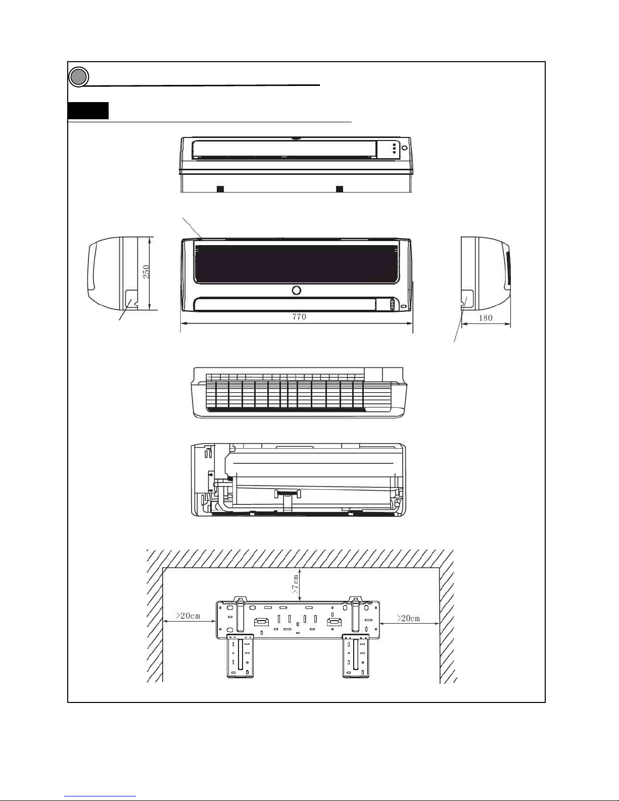
Outline dimension (W/D/H)
(mm)
770×180×250
Package dimension (W/D/H)
(mm)
855×270×336
Indoor
unit
Net weight/gross weight (kg) 8.5/12.5
2
Page 8
—7—
Model
PRO AIR 107 IN / PRO AIR 107 OUT PRO AIR 109 IN / PRO AIR 109 OUT
Compressor type GK080PAD C-1RV096H1A
Compressor type Rotary type
Locked rotor current 17 17
Compressor running current 3.2 3.8
Compressor input power 682 810
Compressor overload model M RA12009-12026 M RA98635-9201
Throttling method Capillary
Starting mode Capacitor CBB65 (22.5uF/450VAC)
Working temperature range -7~43℃
Condenser Aluminum fin-copper tube
Pipe diameter Φ9.52
Row-fin distance (mm) 2-1.6 2-1.4
Developed area of heat exchanger
(I×H×L)
673×406×44 791×508×44
Fan motor speed (rpm) 950 830
Motor rated power (W) 20 30
Fan motor running current (A) 0.42 0.26
Fan capacitor (μf) 1.5 2
Fan type-piece /
Fan type-piece Axial flow fan -1
Fan diameter (mm) Φ320 Φ400
Defrosting method Auto
Climate type T1
Insulation class I
Waterproof level IP24
Maximum working pressure of
exhaust side (Mpa)
3.8
Maximum working pressure of
exhaust side (Mpa)
1.2
Noise(sound pressure level)
dB(A)
52 56
Noise (sound pressure level)
dB(A)
62 66
Outline dimension (W/D/H)(mm) 660×260×430 848×320 ×540
Package dimension (W/D/H)(mm) 765×350×500 878×360 ×600
Net weight/gross weight (kg) 25/29 30/34
Outdoor
unit
Refrigerant/refrigerant charge (kg) R410A /0.88 R410A /1.1
Length 4
Liquid pipe (mm) Φ6 Outer
diameter
Gas pipe (mm) Φ9.52
Height (m) 5
Connection pipe
Maximu
m
distance
Length (m) 10
Page 9
—8—
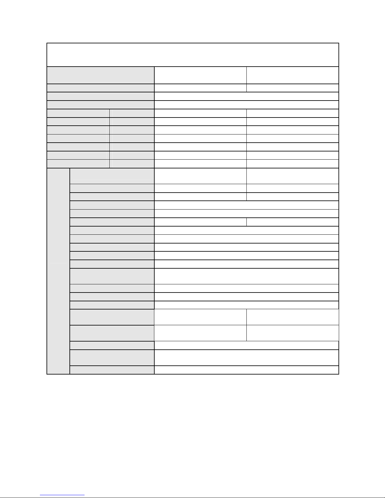
Model PRO AIR 112 IN PRO AIR I109 IN
Function Cooling Heating Cooling Heating
Rated voltage 230V
Rated frequency 50Hz
Capacity (W) 3200 3400 2500 2700
Nominal power (W) 1060 1220 730 800
Max. power (W) 1390 1370 1246 1297
Greatest currency (A) 7.2 7.4 5.7 6
Air flow (m3/h) 450 450
Dry capacity (L/h) 1.2 1.2
C.O.P/EER (W/W) 3 2.8 3.4 3.4
Model KFR-32G/NaA121-E KFR-25G/NaA12F-E
Fan speed (r/min)(H/M/L) 1160/1010/890 1190/1090/990
Output power (W) 14 14
Auxiliary electric heater power /
Fan capacitor 1
Fan motor running current 0.12 0.12
Fan type-piece Cross flow fan-1
Diameter-length (mm) Φ97×583
Evaporator Aluminum fin-copper tube
Pipe diameter Φ7
Row-fin distance (mm) 2-1.4
Developed area of heat exchanger
(I×H×L)
580mm ×228.6mm×25.4mm
Swing motor model MP24GA
Motor power (W) 2
Fuse (A) PCB3.15A Transformer 0.2A
Noise (sound pressure level)
dB(A)
42/39/36
42/39/36
Noise (sound pressure level)
dB(A)
52/49/46 52/49/46
Outline dimension (W/D/H) (mm) 770×180×250
Package dimension (W/D/H) (mm)
855×270×336
Indoor
unit
Net weight/gross weight (kg) 8.5/12.5
Page 10
—9—
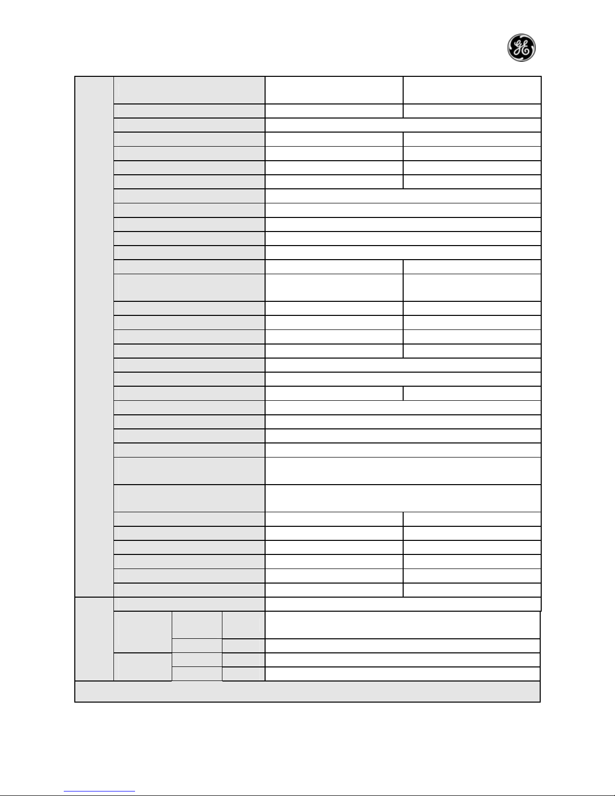
Model PRO AIR 112 OUT PRO AIR 109 OUT
Compressor type C-RV133H1A EU1011DV
Compressor type Rotary type
Locked rotor current 24 33.5
Compressor running current 5.25 4
Compressor input power 1125 628
Compressor overload model B210-145-241E 4CYC11233
Throttling method Capillary
Starting mode Capacitor
Working temperature range -7~43℃
Condenser Aluminum fin-copper tube
Pipe diameter Φ9.52
Row-fin distance (mm) 2-1.4 2-1.4
Developed area of heat exchanger
(I×H×L)
791×508×44 645×508×44
Fan motor speed (rpm) 830 830
Motor rated power (W) 30 30
Fan motor running current (A) 0.26 0.3
Fan capacitor (μf) 2.5 2.5
Fan type-piece /
Fan type-piece Axial flow fan-1
Fan diameter (mm) Φ400 Φ400
Defrosting method Auto
Climate type T1
Insulation class I
Waterproof level IP24
Maximum working pressure of
exhaust side (Mpa)
3.8
Maximum working pressure of
exhaust side (Mpa)
1.2
Noise (sound pressure level) dB(A) 56 54
Noise (sound pressure level) dB(A) 66 64
Outline dimension (W/D/H) (mm) 848×320 ×540 848×320 ×540
Package dimension (W/D/H) (mm) 878×360 ×600 878×360 ×600
Net weight/gross weight (kg) 30/34 41/43
Outdoo
r unit
Refrigerant/refrigerant charge (kg) R410A /1.3 R410A /1.2
Length 4
Liquid pipe (mm) Φ6 Outer
diameter
Gas pipe (mm) Φ9.52
Height (m) 5
Connection
pipe
Maximum
distance
Length (m) 10
Page 11
—10—
Model PRO AIR I112 IN PRO AIR 218 IN
Function Cooling Heating Cooling Heating
Rated voltage 230V
Rated frequency 50Hz
Capacity (W) 3200 3400 2500×2 2800×2
Nominal power (W) 1000 1100 830×2 900×2
Max. power (W) 1361 1383 1120×2 1100×2
Greatest currency (A) 5.9 6.1 5.9×2 5.4×2
Air flow (m3/h) 450 450
Dry capacity (L/h) 1.2
1.2×2
C.O.P/EER (W/W) 3.2 3.1 3 3.1
Model
KFR-32G/NaA12F-E KFR-25X2G/NaA121-E
Fan speed (r/min)(H/M/L) 1190/1090/990 1160/1010/890
Output power (W) 14 14
Auxiliary electric heater power /
Fan capacitor 1
Fan motor running current 0.12 0.12
Fan type-piece Cross flow fan-1
Diameter-length (mm) Φ97×583
Evaporator Aluminum fin-copper tube
Pipe diameter Φ7
Row-fin distance (mm) 2-1.4
Developed area of heat
exchanger (I×H×L)
580mm ×228.6mm×25.4mm
Swing motor model MP24GA
Motor power (W) 2
Fuse (A) PCB3.15A Transformer 0.2A
Noise (sound pressure level)
dB(A)
42/39/36
42/39/36
Noise (sound pressure level)
dB(A)
52/49/46 52/49/46
Outline dimension (W/D/H)
(mm)
770×180×250
Package dimension (W/D/H)
(mm)
855×270×336
Indoor
unit
Net weight/gross weight (kg) 8.5/12.5
Page 12
—11—
Model PRO AIR I112 OUT PRO AIR 218 OUT
Compressor type EU1011DV 5PS108EAA22
Compressor type Rotary type
Locked rotor current 33.5 18
Compressor running current 4 4.05
Compressor input power 628 880
Compressor overload model 4CYC11233 7100819 (KA-122-LPD021A)
Throttling method Capillary
Starting mode Capacitor
Working temperature range -7~43℃
Condenser Aluminum fin-copper tube
Pipe diameter Φ9.52
Row-fin distance (mm) 2-1.4 2-1.8
Developed area of heat exchanger (I×H
×L)
645×508×44 730×660×44
Fan motor speed (rpm) 830 815
Motor rated power (W) 30 60
Fan motor running current (A) 0.3 0.6
Fan capacitor (μf) 2.5 3
Fan type-piece /
Fan type-piece Axial flow fan-1
Fan diameter (mm) Φ400 Φ400
Defrosting method Auto
Climate type T1
Insulation class I
Waterproof level IP24
Maximum working pressure of exhaust
side (Mpa)
3.8
Maximum working pressure of exhaust
side (Mpa)
1.2
Noise (sound pressure level) dB(A) 54 60
Noise (sound pressure level) dB(A) 64 70
Outline dimension (W/D/H) (mm) 848×320 ×540 950×340×685
Package dimension (W/D/H) (mm) 878×360 ×600 1100×450×750
Net weight/gross weight (kg) 41/43 65/70
Outdoo
r unit
Refrigerant/refrigerant charge (kg) R410A /1.2 R410A /0.9×2
Length 4
Liquid pipe (mm) Φ6 Outer
diameter
Gas pipe (mm) Φ9.52
Height (m) 5
Connection
pipe
Maximum
distance
Length (m) 10
Page 13
—12—
Model
GE AIR 326 IN1 / GE AIR 326 IN2 / GE
AIR 326 OUT
GE AIR 428 IN / GE AIR 428 OUT
Function Cooling Cooling
Rated voltage 230V
Rated frequency 50Hz
Capacity (W)
6800 (3200+1800×2) 7200 (1800X4)
Nominal power (W) 6800 (3200+1800×2) 2900 (1450X2)
Max. power (W)
3400 (1700×2) 3400 (1700X2)
Greatest currency (A) 6.5+6.5 6.5+6.5
Air flow (m3/h) 450 450
Dry capacity (L/h) 1.2×2 1.2×2
C.O.P/EER (W/W) 2.4 2.5
Model
KF-18X2G/NA12-E /
KF-32G/NA12-E
KF-18X4G/NA12-E
Fan speed (r/min) (H/M/L) 1160/1010/890 1160/1010/890
Output power (W) 14 14
Auxiliary electric heater power /
Fan capacitor 1
Fan motor running current 0.12 0.12
Fan type-piece Cross flow fan-1
Diameter-length (mm) Φ97×583
Evaporator Aluminum fin-copper tube
Pipe diameter Φ7
Row-fin distance (mm) 2-1.4
Developed area of heat
exchanger (I×H×L)
580mm ×228.6mm×25.4mm
Swing motor model MP24GA
Motor power (W) 2
Fuse (A) PCB3.15A Transformer 0.2A
Noise (sound pressure level)
dB(A)
42/39/36
42/39/36
Noise (sound pressure level)
dB(A)
52/49/46
52/49/46
Outline dimension (W/D/H) (mm) 770×180×250
Package dimension (W/D/H)
(mm)
855×270×336
Indoor
unit
Net weight/gross weight (kg) 8.5/12.5
Page 14
—13—
Model
GE AIR 326 IN1 / GE AIR 326 IN2 /
GE AIR 326 OUT
GE AIR 428 IN / GE AIR 428 OUT
Compressor type C-RV237H01AA C-RV237H01AA
Compressor type Rotary type
Locked rotor current 31 31
Compressor running current 6.3 6.3
Compressor input power 1100 1100
Compressor overload model MRA98619-9200 MRA98619-9200
Throttling method Capillary
Starting mode Capacitor
Working temperature range -5~43℃
Condenser Aluminum fin-copper tube
Pipe diameter Φ9.52
Row-fin distance (mm) 2-1.8 2-1.8
Developed area of heat exchanger
(I×H×L)
791×508×44 791×508×44
Fan motor speed (rpm) 780 780
Motor rated power (W) 60 60
Fan motor running current (A) 0.56 0.56
Fan capacitor (μf) 3 3
Fan type-piece /
Fan type-piece Axial flow fan-1
Fan diameter (mm) Φ460 Φ460
Defrosting method Auto
Climate type T1
Insulation class I
Waterproof level IP24
Maximum working pressure of
exhaust side (Mpa)
2.5
Maximum working pressure of
exhaust side (Mpa)
0.6
Noise (sound pressure level) dB(A) 58 58
Noise (sound pressure level) dB(A) 68 68
Outline dimension (W/D/H) (mm) 950×412 ×840 950×412 ×840
Package dimension (W/D/H) (mm) 1100×450×920 1100×450×920
Net weight/gross weight (kg) 72/77 72/77
Outdoo
r unit
Refrigerant/refrigerant charge (kg) R407C /1.27×2 R407C /1.27×2
Length Length of connecting tube
Liquid
pipe
(mm) Φ6 Outer
diameter
Gas pipe (mm) Φ9.52
Height (m) 5
Connection pipe
Maximum
distance
Length (m) 10
The above data is subject to change without notice. Please refer to the nameplate of the unit.
Page 15
—14—
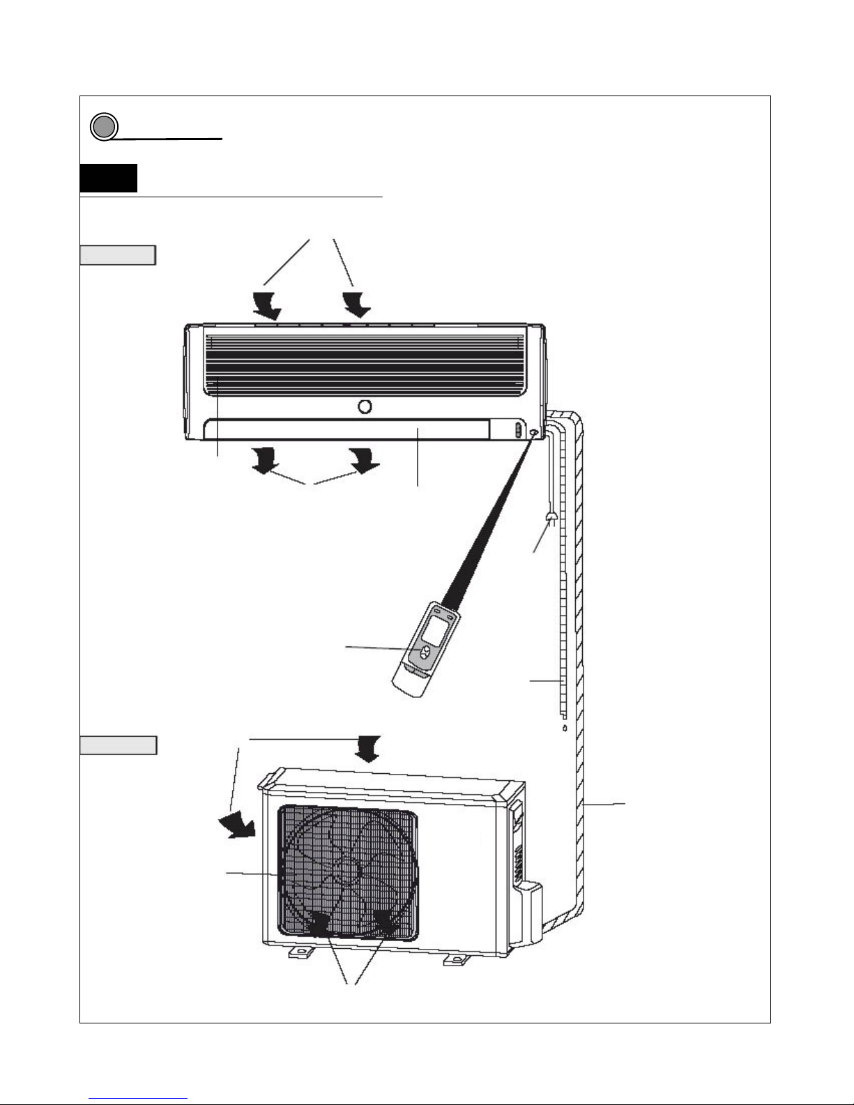
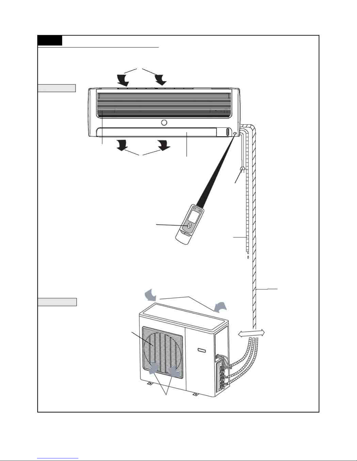
Part name
Part name of one driving one unit
Air in
Indoor unit
Panel
Air out Air guide board
Power plug
Remote controller
Drainage pipe
utdoor unit Air in
Connecting pipe and
connecting wire
Air outlet vent grill
Air out
3
3.1
Page 16
—15—
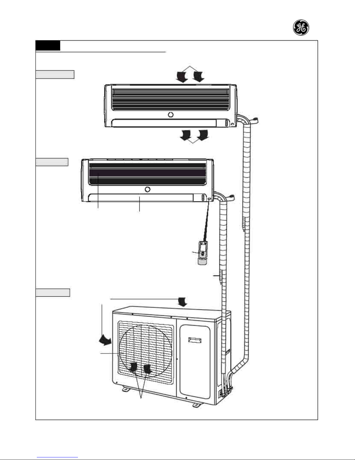
3.2 Part name of one driving two unit
Air in
Indoor unit A
Wrapping tape
Air out
Indoor unit B
Panel
Air guide board
Remote controller
Drainage pipe
Outdoor unit
Air in
Air outlet vent grill
Air out
Page 17
—16—
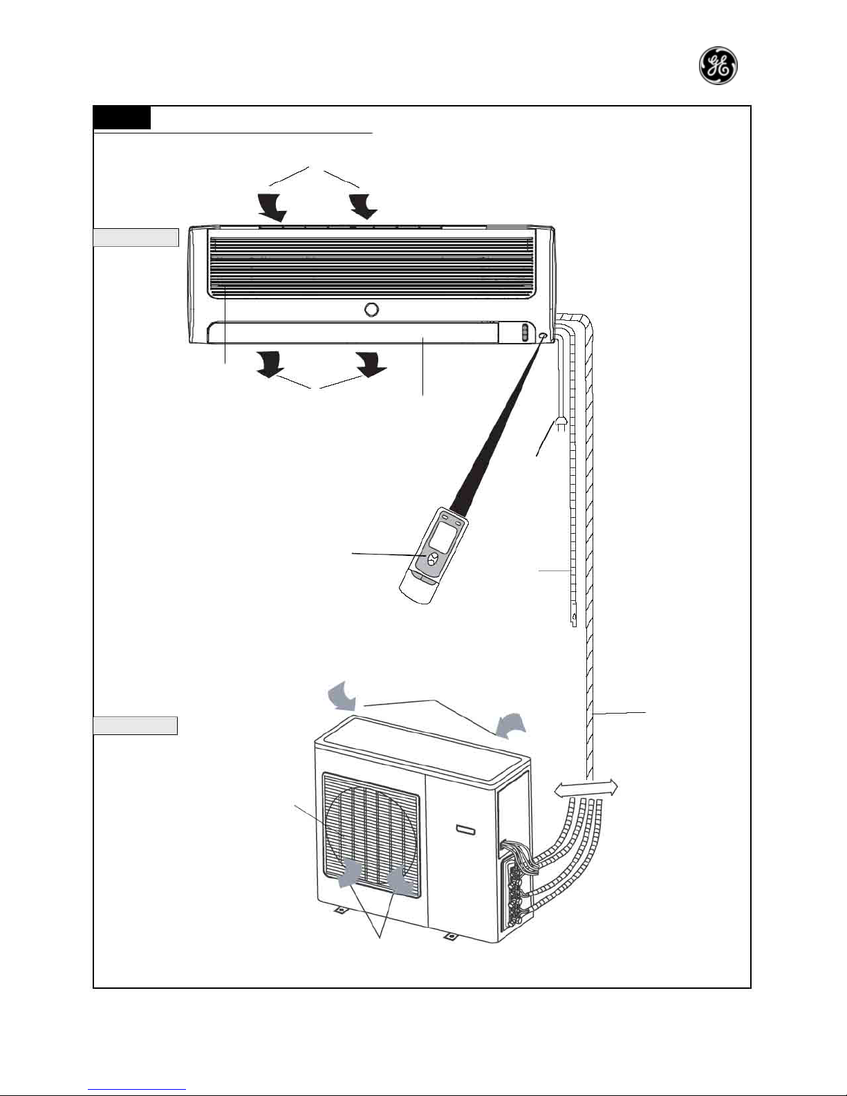
3.3 Part name of one driving three unit
Air in
Indoor unit
Panel
Air out Air guide board
Power plug
Remote controller
Drainage pipe
Air in
Outdoor unit
Air outlet vent grill
Air out
Connecting
pipe and
connecting
wire
Page 18
—17—
P17
3.4
Part name of one driving four unit
Air in
Indoor unit
Panel
Air out Air guide board
Power plug
Remote controller
Drainage pipe
Air in
Outdoor unit
Air outlet vent grill
Air out
Connecting
pipe and
connecting
wire
Page 19
—18—
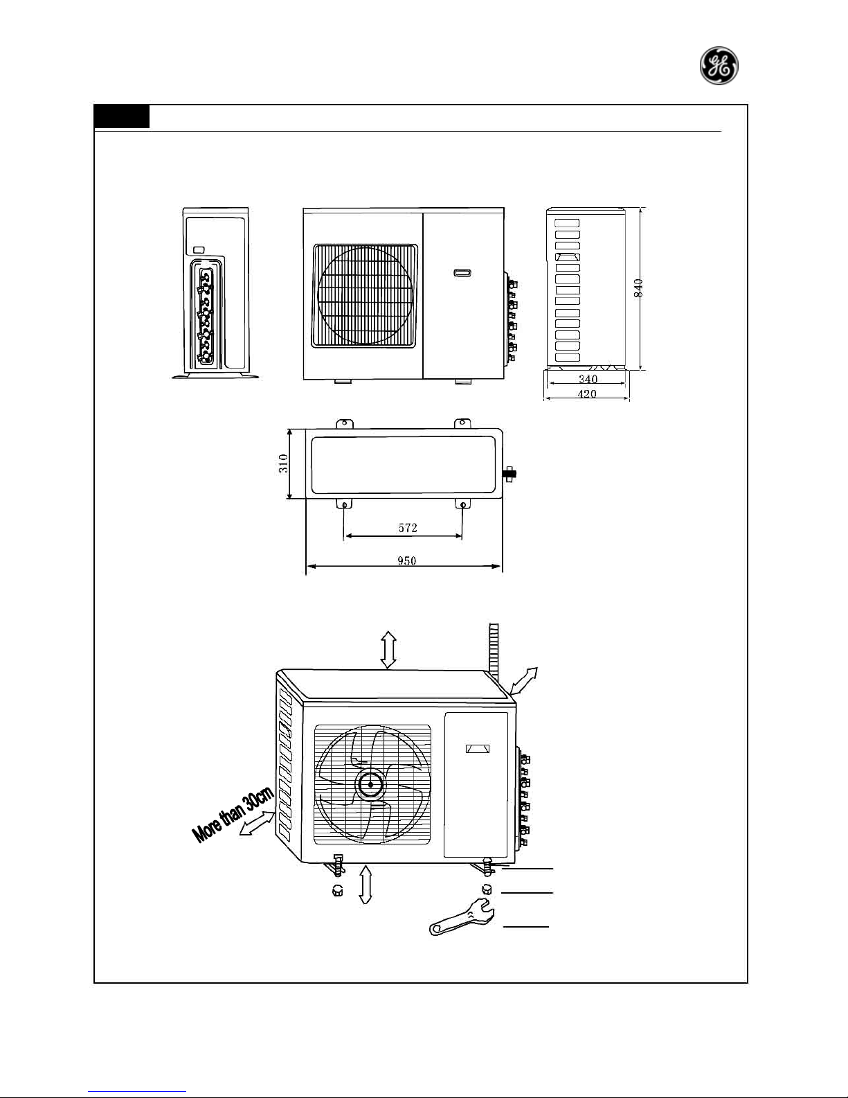
Outline and installation dimensions
4.1 Outline and installation dimensions of indoor unit
Air inlet vent
Left pipe outlet
Right pipe outlet
Rear view
Ceiling
Left side Right side
Installation dimensions
4
Page 20
—19—
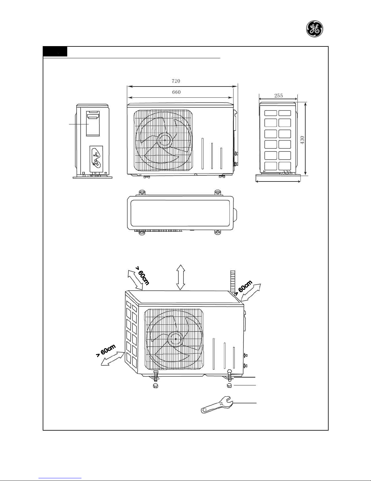
4.2 Outline and installation dimensions of indoor unit 20
Handle
> 60cm
Bolt
Nut
Spanner
Page 21
—20—
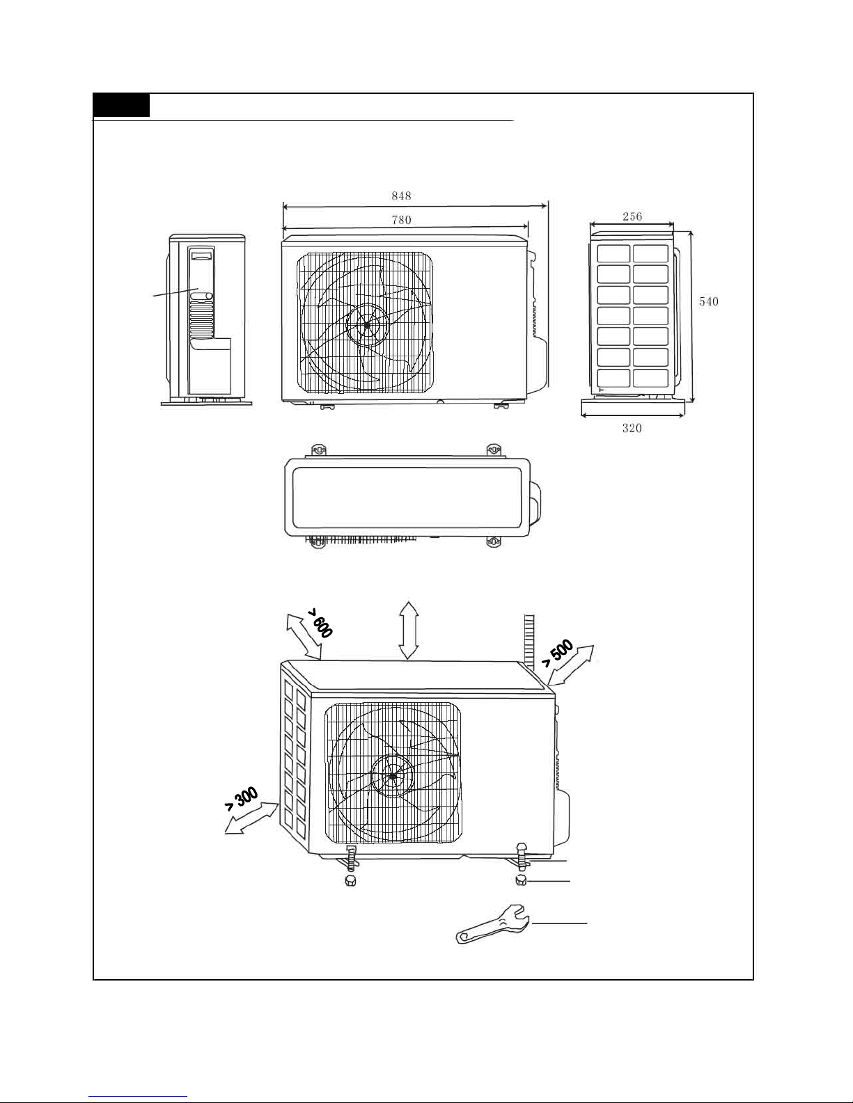
4.3 Outline and installation dimensions of indoor units 2 5, 32
Handle
Unit: mm
> 500
Bolt
Nut
Spanner
Page 22
—21—
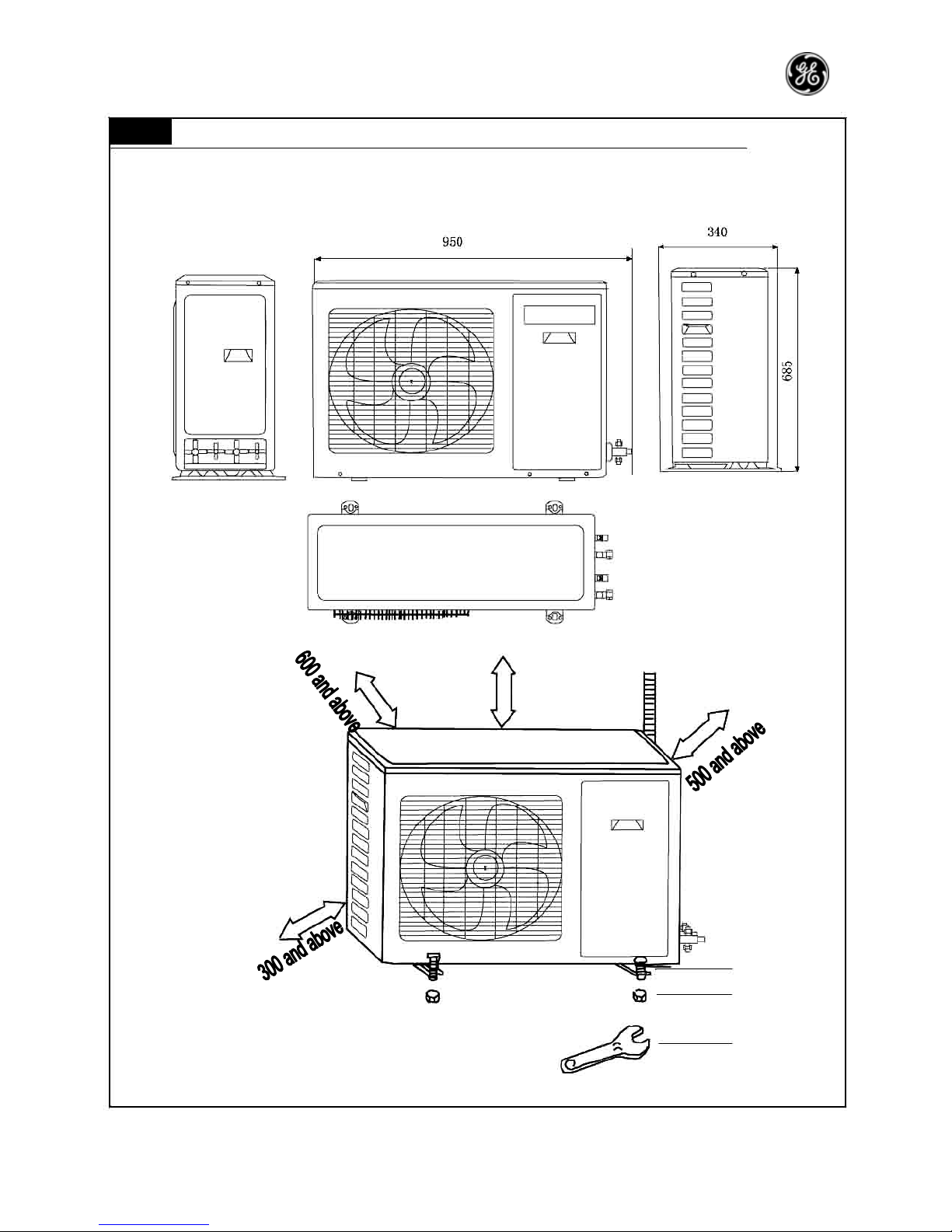
4.4 Outline and installation dimensions of one driving two outdoor unit
Unit: mm
500 and above
Bolt
Nut
Spanner
Page 23
—22—
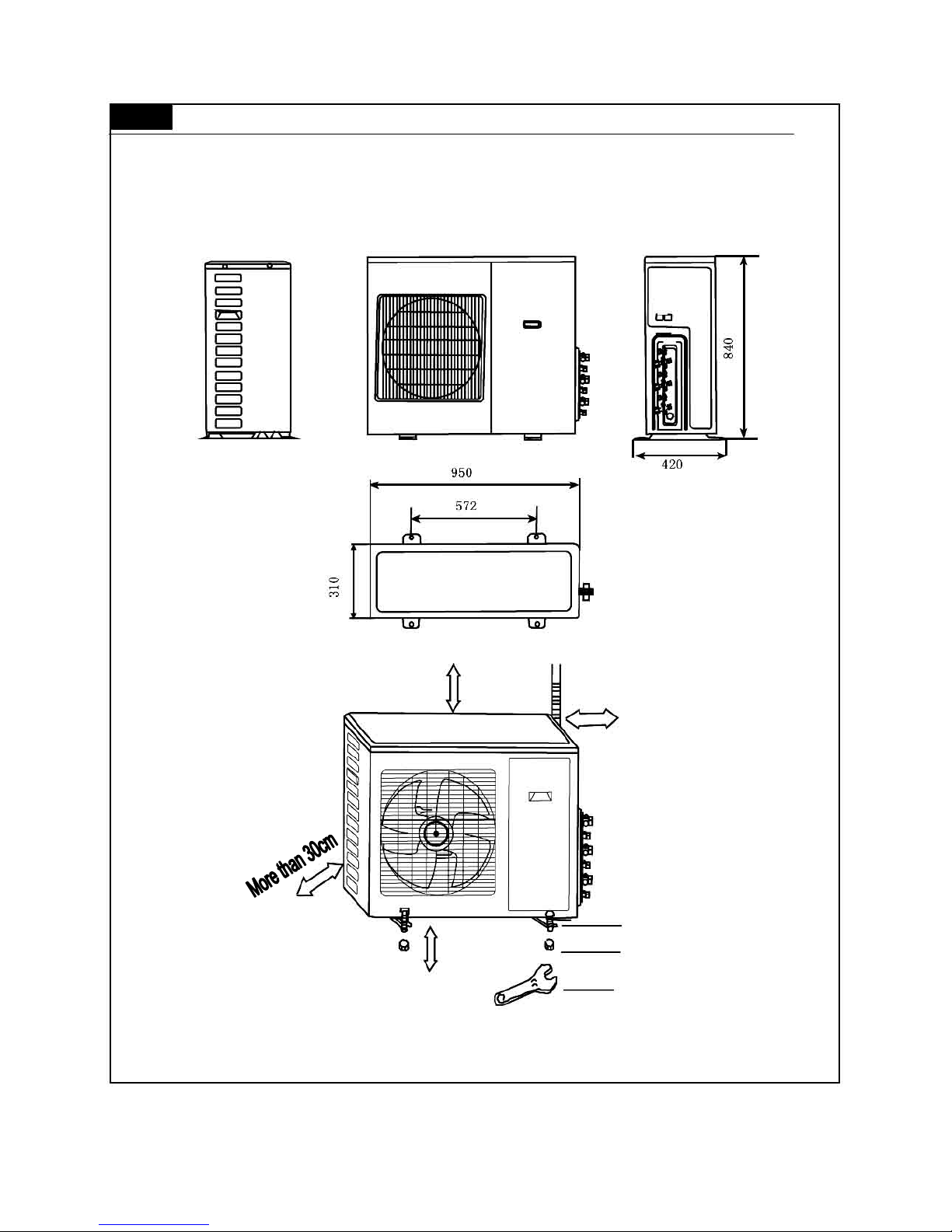
4.5 Outline and installation dimensions of one driving three outdoor unit
More than 50cm
More than 30cm
Bolt
More than 200cm Nut
Spanner
Page 24
—23—
4.6 Outline and installation dimensions of one driving four outdoor unit
More than 50cm
More than 30cm
Bolt
More than 200cm Nut
Spanner
Page 25
—24—
5
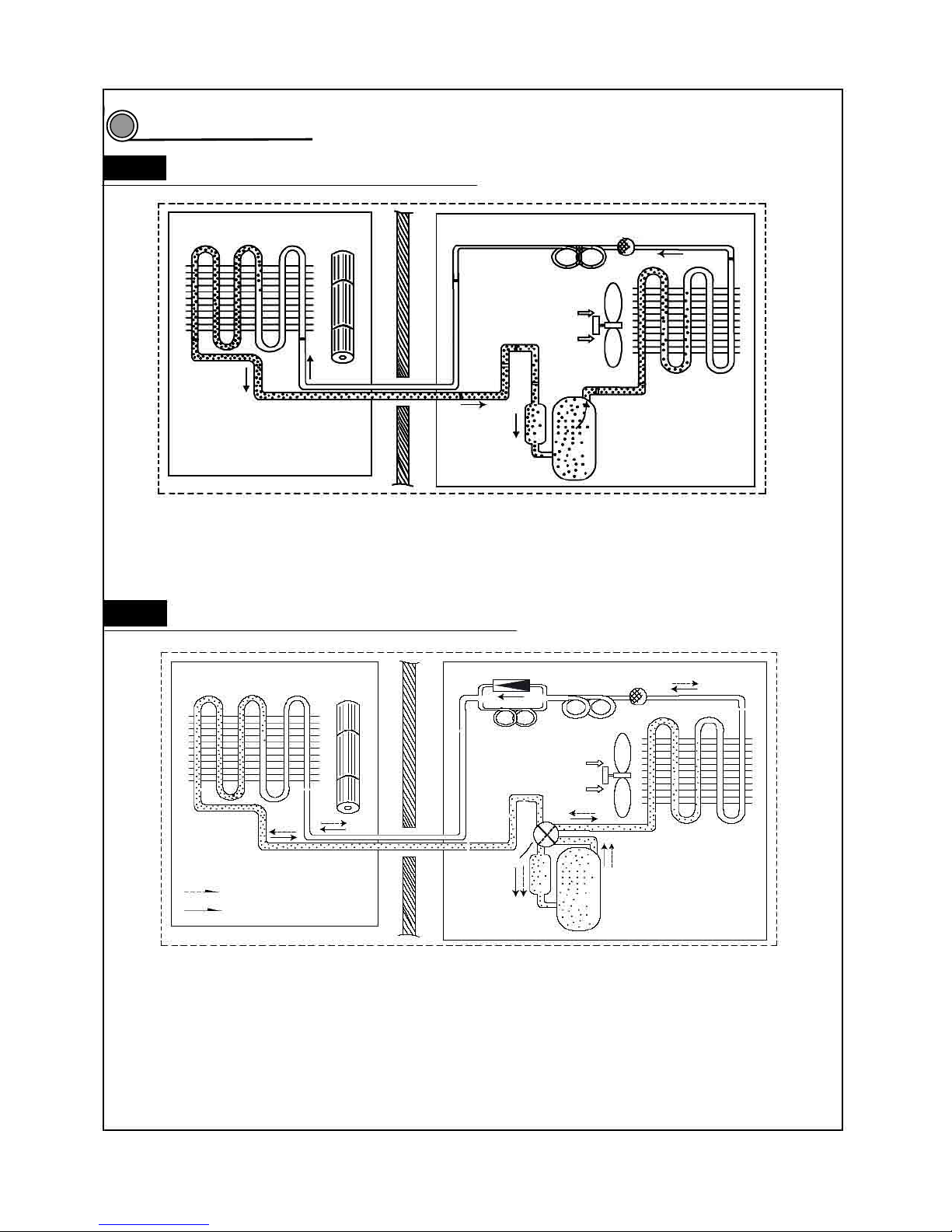
System diagram
5.1 Cool only system circuit diagram
Evaporator Cross flow fan
Capillary Filter
Axial flow fan
Condenser
Gas liquid
separator Compressor
When the power is on, indoor and outdoor units will start to run. The compressor sucks low-pressure refrigerant gas from
the evaporator of indoor unit and then discharges high-temperature, high-pressure refrigerant gas into outdoor
condenser. Then air exchanges the heat with outdoor air and becomes refrigerant liquid. The liquid is throttled by the
capillary and changes into low-temperature and low-pressure liquid and then flows into indoor evaporator. Then liquid
exchanges the heat with the required air and changes into low-temperature and low-pressure refrigerant gas. The cycle
introduced above goes on and on, and the demanded low temperature environment is maintained
5.2 Cool/Heat system circuit diagram
Evaporator Cross flow fan
Flow direction of refrigerant when heating
Flow direction of refrigerant when cooling
One-way valve
Main capillary Filter
Auxiliary Capillary
Axial flow fan
Condenser
Electromagnetic
four-way valve
Gas liquid
Separator Compressor
When the power is on, indoor and outdoor units will start to run. When the system operates in cool mode, the
compressor sucks low-temperature, low-pressure refrigerant gas from indoor evaporator and then discharges
high-temperature, high-pressure refrigerant gas into outdoor heat exchanger. With the help of axial flow fan, the gas
transfers its latent heat into outdoor air and becomes high-pressure refrigerant liquid. The liquid is throttled by the
capillary and changes into low-temperature and low-pressure liquid and then flows into indoor heat exchanger. With the
help of centrifugal fan, the liquid evaporates into low-temperature refrigerant gas and indoor air is cooled down. The
refrigerant gas is sucked into the compressor and the cycle introduced above goes on and on, and the demanded low
temperature environment is maintained. When the system operates in heat mode, four-way valve changes its way and
the refrigerant flows into the reversible cycle as the cool mode. The refrigerant discharges its latent heat in the indoor
heat exchanger, and sucks heat from outdoor heat exchanger and forms the heat pump cycle. This cycle goes on and on,
and the demanded high temperature environment is maintained.
5
Page 26
—25—
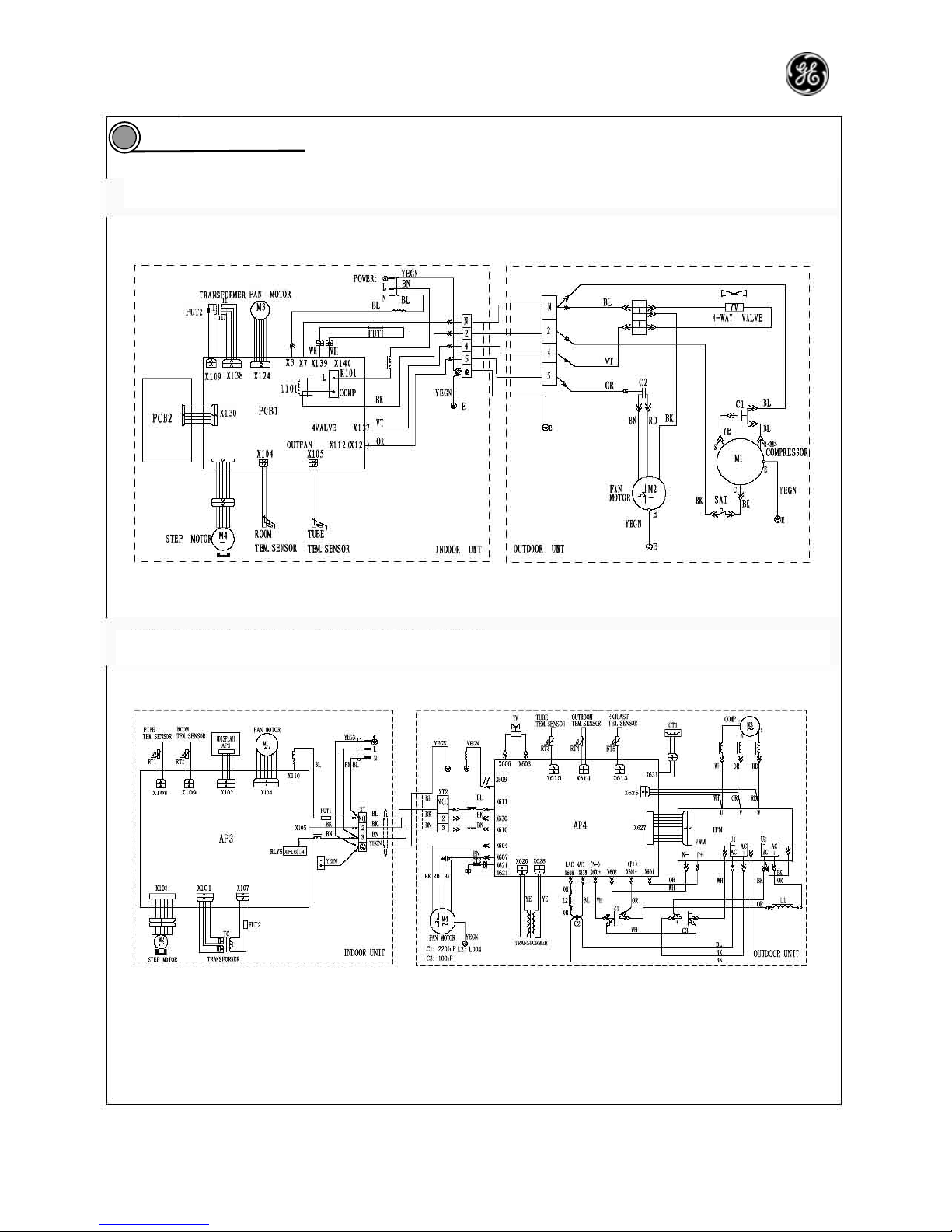
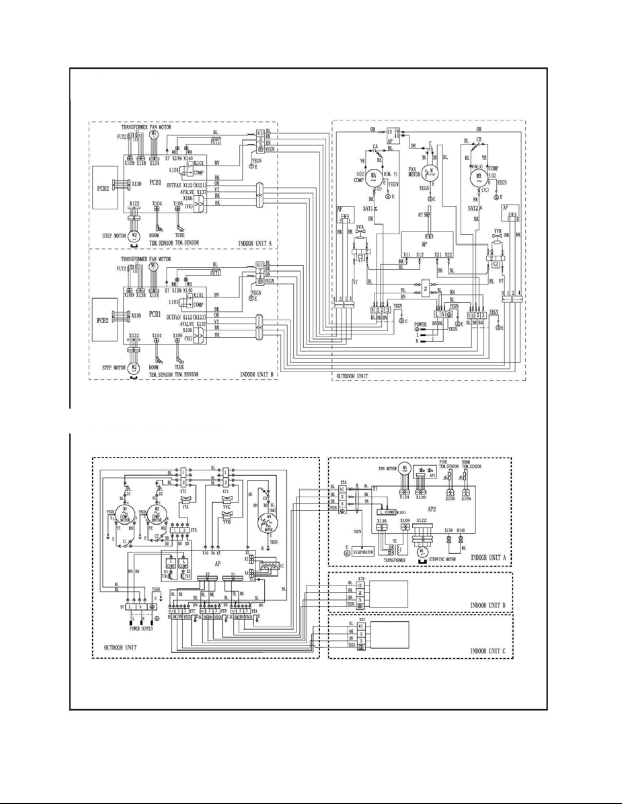
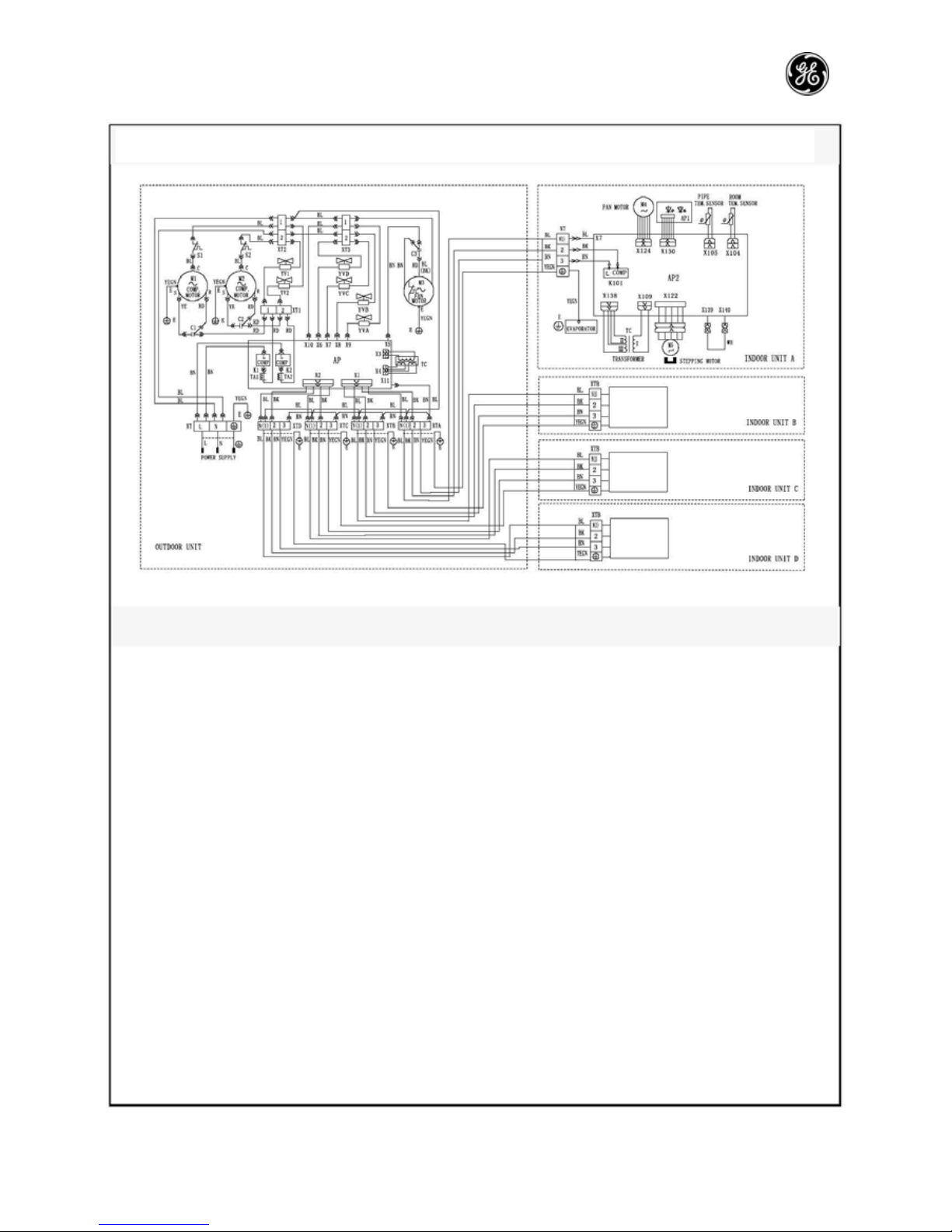
Circuit diagram
6
PRO AIR 107 IN / PRO AIR 107 OUT; PRO AIR 109 IN / PRO AIR 109 OUT; PRO AIR 112 IN / PRO
PRO AIR I109 IN / PRO AIR I109 OUT; PRO AIR I112 IN / PRO AIR I112 OUT
Page 27
—26—
Circuit
diagram is
same as
above.
Circuit
diagram is
same as
above.
PRO AIR 218 IN / PRO AIR 218 OUT
GE AIR 326 IN1 / GE AIR 326 IN2 / GE AIR 326 OUT
Page 28
—27—
Circuit
diagram is
same as
above.
Circuit
diagram is
same as
above.
Circuit
diagram is
same as
above.
These circuit diagrams are subject to change without notice. Please refer to the one supplied with the unit.
GE AIR 428 IN / GE AIR 428 OUT
Page 29
—28—
Function manual and operation method of remote controller
PRO AIR I112 IN / PRO AIR I112 OUT, suitable for frequency converter
Function manual of remote controller
7.1.1 Temperature parameter
Room set temperature: (T
set
)
Room ambient temperature: (T
amb
)
7.1.2 Basic function of system
No matter what mode the compressor is in, the minimum time interval between two startups should be 3
minutes after it is powered on.
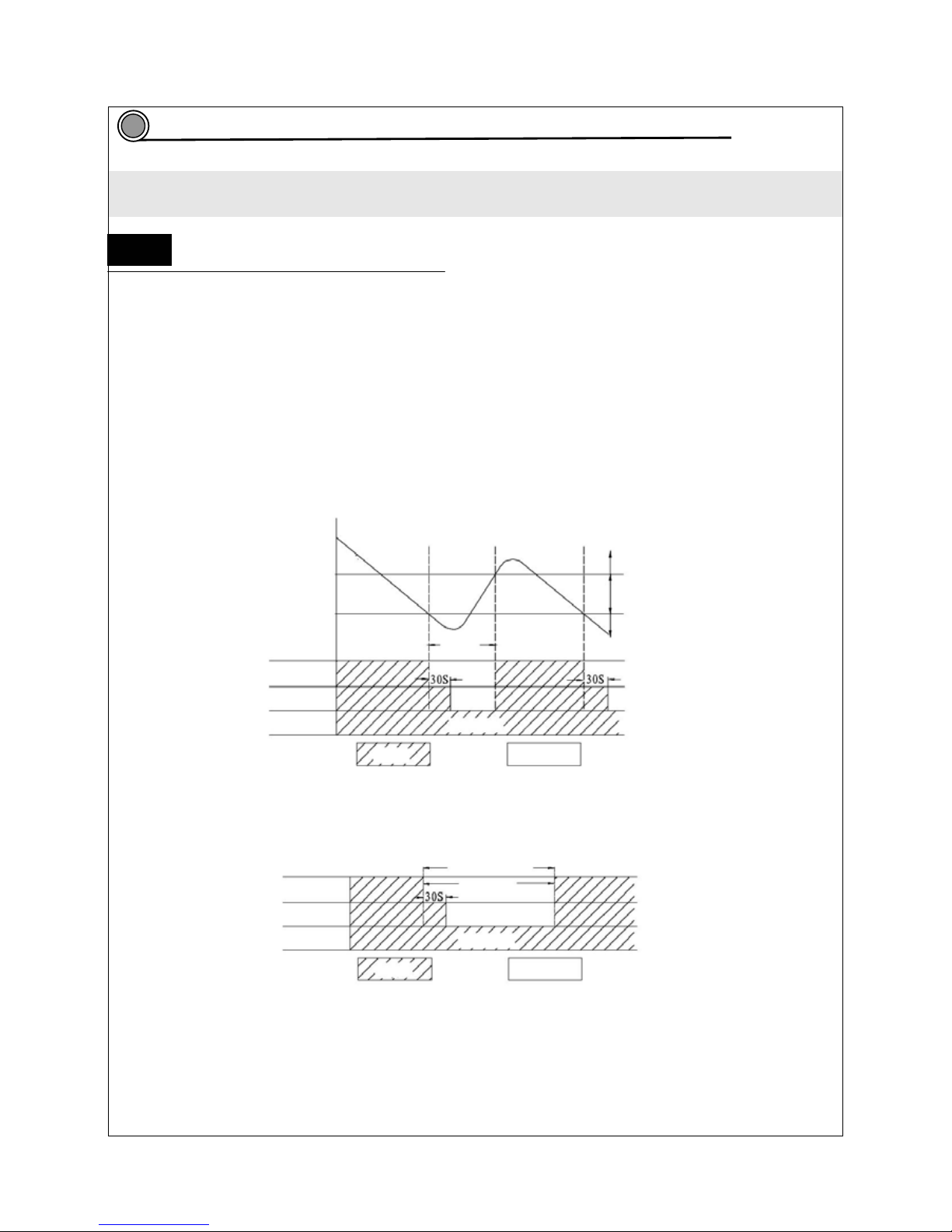
7.1.2.1 Cooling mode
7.1.2. 1.1 The condition and process of cooling
If T
amb>Tset
, COOL mode will act, compressor and external fan will run, the indoor fan will run at the set
speed.
If T
amb≤Tset
-2℃, compressor will stop and external fan will stop after a delay of 30s. The indoor fan will
run at the setting speed.
If Tset-2℃<T
amb<Tset
, the unit will keep ℃ on running in the original mode.
¾ In this mode, the reversal valve will not be powered on and the temperature setting range is
16 ~30℃℃.
T
set
+1℃ T
amb
Start cooling
T
set
-1℃ Keep running in the original mode
Stopping cooling
≥3min
Compressor
Outdoor fan
Indoor fan Set fan speed
Run Stop
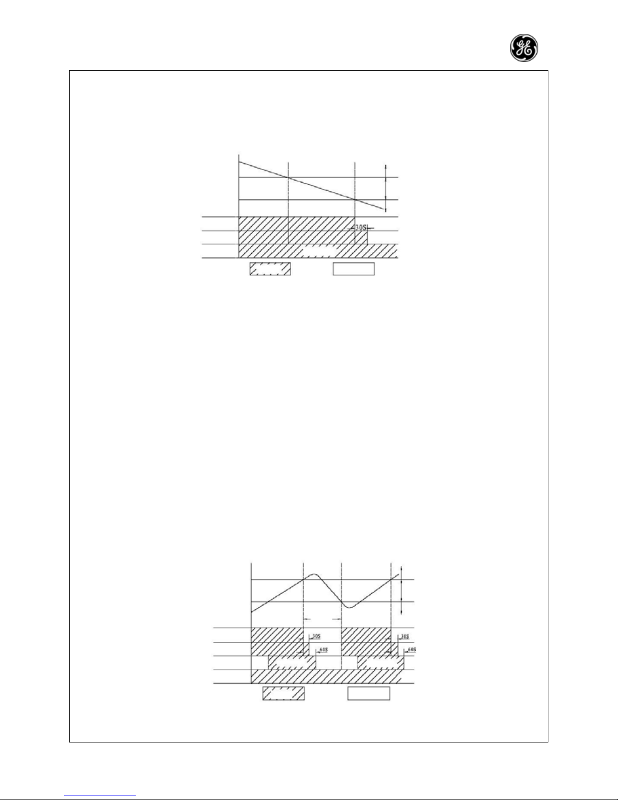
7.1.2.1.2 Protection function
Anti-freezing Protection
When the anti-freezing protection is detected, the compressor will stop, the outdoor fan will stop after a
delay of 30 seconds. The indoor fan and swing motor will keep on running in the original mode. When
anti-freezing protection is eliminated and compressor has stopped for 3min, the machine restores its
former operation mode.
Anti-freezing Protection
Compressor ≥3min
Outdoor fan
Indoor fan Set fan speed
Run Stop
Over current protection
The compressor will run at a limited frequency when the total current is high. The compressor will stop
when the total current is too high and the outdoor unit will stop after a delay of 30s.
7.1.2.2 Dry mode
7.1.2.2.1 The condition and process of dry mode
If T
amb>Tset
, the drying mode will act. The compressor and external fan will run, and the indoor fan will run
at a low speed.
7
7.1
Page 30
—29—
If T
set
-2℃≤T
amb≤Tset
, the unit will keep on running in the original mode.
If T
amb≤Tset
-2℃, the compressor will stop. The external fan will stop after a delay of 30s, and the indoor
fan will run at a low speed.
¾ In this mode, the reversal valve will not be powered on and the temperature setting range is
16 ~30℃℃
T
amb
T
set
T
set
-2℃
Compressor
Outdoor fan
Indoor fan Low fan speed
Run Stop
Cooling running
Dry running
Stop running
7.1.2.2.2 Protection function
Anti-freezing protection
Anti-frost protection same as cooling
Over current protection
Over current protection is the same as the cooling mode.
7.1.2.2.3 SWING mode
At this mode, the inner fan will select among high, medium, low and auto modes and the compressor,
outer fan and 4-way fan will stop running.
¾ In this mode, the reversal valve will not be powered on and the temperature setting range is
16 ~30℃℃
7.1.2.3 HEAT mode
7.1.2.3.1 Running condition and process of heating mode
If T
amb≤Tset
+2 , HEAT mode will act, the compressor, outdoor fan and reversal valve will run at the same ℃
time, the indoor fan will run after 3 minutes’ delay at the latest.
If T
amb≥Tset
+4 , the compressor will stop℃ first and 15s later, the outdoor unit will stop. The reversal valve
will keep power-on and the indoor fan will run at a low speed and will stop 30s later.
If T
set
+2℃<T
amb<Tset
+4 ,℃ the unit will keep running in the previous mode.
¾ In this mode, the temperature setting range is 16 ~30 .℃℃
¾ The air conditioner will adjust the running frequency of the compressor automatically according to the
change of ambient temperature.
¾ The 4-way valve will be cut off 2min after the compressor stops operation when heating cut-off, or
heating mode changed to other mode.
T
set
+5℃
T
set
+2℃ T
amb
≥3min
Stop heating
Original running state
Start heating
Compressor
Outdoor fan
Indoor fan ≤3min Set fan speed ≤3min Set fan speed
Reversal valve
Run Stop
7.1.2.3.2 The condition and process of defrosting
When frost is detected in the condenser, the system will enter into defrosting mode. When the defrosting starts,
the compressor and indoor fan stop running. The outdoor fan will stop after a delay of 30s, and the four-way
Page 31

—30—
valve will stop running after a delay of 30s. The defrosting will start 15s later. After the compressor runs for 7
min or when the defrosting is finished, the compressor will stop, and 30s later the four-way valve will run. 30s
later, the compressor and outdoor fan resume to operation and indoor fan will run after a delay of 3min. Prior to
entering into defrost, if the auxiliary heating is running, then, for defrosting, the auxiliary heating will be stopped
firstly, and 5s later the indoor fan will stop. The indoor fan will run at blowing residual heat mode when the
compressor stops due to failure at heating mode.
¾ In this mode, the reversal valve will not be powered on and the temperature setting range is 16 ~30℃℃
7.1.2.3.3 Protection function
Anti-high temperature protection
If the evaporator is detected with a high pipe temperature, the outer fan stops running and if the evaporator
recovers to a normal pipe temperature, the outer fan resumes running.
Noise immunization protection
When "RUN/STOP" is used to turn off the unit, the reversal valve will delay 2 minutes to stop.
Over current protection
Over current protection is the same as the cooling mode
Auxiliary electrical heating power
Operation condition of auxiliary electric heating: for heating mode and when compressor is powered on, and
when the pipe temperature is detected to be too low with the indoor fan running at medium or high speed, the
auxiliary electric heating will be put into operation. When the compressor is powered on, and when the pipe
temperature is detected to be too low with the indoor fan running at low speed, the auxiliary electric heating will
be put into operation.
Stop condition of auxiliary electric heating: when the compressor stops or the pipe temperature is too high or
the environmental temperature is too high, the auxiliary electric heating stops operation. The auxiliary electric
heating will stop when there is failure in the communications. Once it stops, it will require 2min to recover the
operation.
7.1.2.4 Dry mode
For air delivery mode, the indoor fan will run at the setting wind speed and the swing motor will run at the
setting mode and the running indicator will be lit.
7.1.2.5 Auto mode
In this mode, the system will automatically select its running mode based on the change of the ambient
temperature (cooling, dry , heating and air supply). The protection function is same as HEAT/COOL mode.
7.1.2.6 Failure indication of general protection functions at various modes
1 Overload protection
When evaporator pipe temperature is detected high, if it is still higher after the compressor runs in a limited
frequency, the compressor will stop running. In auto HEAT or HEAT mode, the indoor fan will blow for 60
seconds and then stop, In other modes, the indoor fan will run at the setting speed and display H4.
¾ Evaporator pipe temperature is the temperature of outdoor heat exchanger when cooling or temperature of
indoor heat exchanger when heating.
2 Compressor delay protection
The compressor will delay 3min to start again after stopping.
3 Compressor discharge temperature protection
When discharge temperature is too high, the compressor will stop and it will resume running after 3 minutes
and display E4.
4 Communications malfunction
Communications malfunction means that no correct signal can be received continuously within 3 minutes. In
this case, the outdoor unit stops operation. The residual heat blowing will be stopped at auto heating or heating
mode. As to other modes, the indoor fan will run at the setting wind speed.
5 Module protection
The compressor will stop at module protection and the compressor will resume back to operation when it has
stopped for 3min.
6 Status of indicator at receiver board of indoor unit
The receiver board indicator at running is at normal status and when the indicator signal received three times
continuously within 6 seconds are not the same as the previous one will be recognized as pressing one time
the indicator button. In this case, the indicator of receiver board will enter into detection mode and will
automatically exit from the detection mode in 3 minutes.
7.1.3 Other controls
7.1.3.1 Power ON/OFF
Each time the On/Off button of the remote controller is pressed, the On/Off mode will be changed over once.
7.1.3.2 Mode selection
Press the MODE button on the remote controller to select and display the following modes: AUTO, COOL, DRY,
FAN, and HEAT.
7.1.3.3 T emperature setting selection button
Each time TEMP or TEMP button is pressed, the setting temperature will be increased or decreased by 1℃,
with the adjusting range being 16~30 . In AUTO mode, this button does not function.℃
7.1.3.4 Time setting button
Time setting button of remote controller: the time selection range is 0-24h, with the minimum unit being 0.5h.
Page 32

—31—
7.1.3.5 Auto button
The system will be stopped if the button is pressed down when the remote controller is powered on, with
the system being operated by remote controller. If the remote controller is powered off, pressing the button
will enter auto run mode and the swing will be turned on. The system will be running in accordance with
the remote controller if there is remote control command.
7.1.3.6 Sleep function
If the sleep function is set up at cooling or drying mode, T
set
will be raised automatically for 1℃ after one
hour, and will be raised for another 1℃ 2 hours later. Then, it will be running at such a setting temperature
and such a setting wind speed.
set
Temperature setting T
set
set
set
1 hour 2 hour Over 2 hour
If the sleep function is set up at heating mode, T
set
will be decreased for 1℃ after one hour, and will be
decreased for 2℃ 2 hours later. Then, it will be running at such a setting temperature and such a setting
wind speed.
1 hour 2 hour Over 2 hour
set
set
Temperature setting T
set
set
In FAN and AUTO mode, the set temperature is fixed.
7.1.3.7 Swing motor control
Use the SWING button of the wireless remote controller to controller SWING On/Off. Swing will only act
when indoor fan is running.
After power on, the stepping motor turns back to 0 position and closes the air outlet vent; after the unit is
turned on, it will turn back to the max. air outlet I position; when in swinging state, it will swing between L
and D position. When the unit is turned off, it will turn back to 0 position.
7.1.3.8 Measurement of maximum cooling capacity, name heating/cooling
Select cooling mode power on with remote controller and press “Light” button to turn on the light. In this
case, a sound from buzzer should be heard. Press “Change air” button to set up for air change 1 (air
change 2), a sound from buzzer should be heard, entering the maximum cooling mode (name cooling).
Afterwards, it is not allowed to press any other button of remote controller. Otherwise, the system will exit
from the maximum cooling mode (name cooling). Select heating mode power on with remote controller
and press “Light” button to turn on the light. In this case, a sound from buzzer should be heard. Press
“Change air” button to set up for air change 1 (air change 2), a sound from buzzer should be heard,
entering the maximum heating mode (name heating). Afterwards, it is not allowed to press any other
button of remote controller. Otherwise, the system will exit from the maximum heating mode (name
heating).
In case the maximum cooling, name cooling and name heating have been properly set up, cancel the
maximum cooling, name cooling and name heating 2 hours later.
Page 33

—32—
7.1.3.9 Power supply of outdoor unit
The power supply for outdoor unit is turned on in AUTO, COOL, HEAT and DRY mode under turn-on state.
The power supply for outdoor unit will delay 3 minutes to turn off under turn-off state or in the FAN mode
under turn-on state.
7.1.3.10 Buzzer
The buzzer will deliver a sound when the remote controller is powered on or an effective remote control
signal is received or when there is button input signal.
7.1.3.11Control of electric heater belt
The two electric heater belts will stop operation when there is failure in environmental temperature sensor of
outdoor unit, otherwise, the control will be carried out in accordance with the following logic:
① If the outdoor environmental temperature is very low and the compressor is not turned on, the electric
heater belt of compressor will operate: otherwise, if the compressor is turned on or the compressor is
not turned on but the outdoor environmental temperature is very high, the electric heater belt will not
operate. If the compressor it not turned on and is in between lower and higher, the electric heater belt of
compressor will keep on the original state.
② If the outdoor environmental temperature is low but higher than mentioned in the above paragraph, the
electric heater belt of compressor will operate: otherwise, if the electric heater belt of compressor does
not operate when the outdoor environmental temperature is very high. If it is between the two
temperatures, the electric heater belt of compressor will keep on the original state.
7.1.3.12 Indoor fan control
The indoor fan may be set up with remote controller to HIGH, MED and LOW, in this case, the fan will run
respectively at high, medium and low speed.
The auto wind speed of indoor fan:
① For cool/heat mode: if the frequency is low, the indoor fan runs at low wind speed;if the frequency is high,
the indoor fan runs at high wind speed.
② For air delivery mode: the auto wind speed is forcedly set up to low wind speed.
7.1.3.13 Power-off memory function
Mode, swing, temperature setting, wind speed setting and timing (in case the power is off when the timer is
due and the power is turned on again, the timer will re-start counting. If the power is turned on again, the
system will operate at the mode after the timer is due).
Page 34

—33—
Suitable to systems except for PRO AIR I109 IN / PRO AIR I109 OUT PRO AIR I112 IN / PRO AIR I112
OUT frequency converter
Function manual of remote controller
7.2.1 Temperature parameter
Room set temperature: (T
set
)
Room ambient temperature (T
amb
)
7.2.2 Basic function of the system
No matter what mode the compressor is in, the minimum time interval between two startups should be 3
minutes after it is powered on.
7.2.2.1 COOL mode
7.2.2.1.1 Running condition and process of cooling
If T
amb≥Tset
+1℃, COOL mode will act, compressor and outdoor fan will run, the indoor fan will run at the
set speed;
If T
amb≤Tset
-1℃, the system enters stop mode. In this case, the compressor will stop first, and the
indoor/outdoor fans will stop after a delay of 15s.
If T
set
-1℃<T
amb<Tset
+1℃, the unit will keep running in the previous mode.
¾ In this mode, the reversal valve will not be powered on and the temperature setting range is 16℃~30
℃
T
amb
T
set
+1℃
T
set
+2℃
≥3 min
Compressor
Outdoor fan
Indoor fan Set fan spee
d Set fan speed
Start cooling
Original running state
Stop cooling
Run Stop
7.2.2.1.2 Protection function
Anti-freezing Protection
When system anti-freezing protection is detected, the compressor and outdoor fan stop running, and the
indoor fan runs at the preset speed. When anti-freezing protection is eliminated and compressor has
stopped for 3min, the machine restores its former operation mode.
Anti-freezing Protection
Compressor ≥3min
Outdoor fan
Indoor fan Set fan speed
Run Stop
Over current protection
When the system current is detected to be higher than the specified value for 3 consecutive seconds, the
system will enter the operation mode of fan only. After 3 minutes, the system resumes back to the original
running mode. If the over current protection is detected for three times consecutively in 30 minutes, the
system will stop running and it is required to turn on the system with remote controller.
7.2.2.2 Dry mode
7.1.2.2.1 The condition and process of dry mode
If T
amb>Tset
+2℃, the cooling mode will act. The compressor and external fan will run, and the indoor fan
will run at an adjustable speed.
7.2
Page 35

—34—
If T
set
-2℃≤T
anp≤Tset
+2℃, the drying mode will act. In this case, the indoor fan will run at low speed. The
compressor and the outdoor fan will stop 6min later. The indoor fan will stop 30s later. The compressor and
the outdoor fan will run 3.5 min later and the indoor fan will run at low speed. The drying process then will
run periodically as given above.
If T
amb<Tset
-2 , ℃ the system enters stop mode. In this case, the compressor will stop first, and the outdoor
fan will stop after a delay of 15s, and then, the indoor fan will stop after another delay of 15s.
¾ In this mode, the reversal valve will not be powered on and the temperature setting range is
16 ~30℃℃
T
amb
T
set
+2℃
T
set
-2℃
6 min 6 min
4 min 4 min
Cooling running
Dry running
Stop running
Compressor
Outdoor fan
Indoor fan
Set fan speed Low speed Low speed
Run Stop
7.2.2.2.2 Protection function
Anti-freezing Protection
If system anti-freezing protection is detected, the compressor will stop, but the outdoor fan will stop after a
delay of 15s. The indoor fan will run at low speed. If the anti-freezing protection is released and the
compressor has stopped for 3 min, the system will resume to original operation mode.
Anti-freezing Protection
Compressor
Outdoor fan
Indoor fan Low fan speed
Run Stop
7.2.2.3 heating mode
7.2.2.3.1 The condition and process of heating
If T
amb≤Tset
+2 , HEAT mode will act℃ . In this case, the compressor, outdoor fan and reversal valve will run at
the same time, the indoor fan will run in accordance with anti-cool condition.
If T
amb ≥Tset
+4 , the compressor ℃ will firstly stop, and the outdoor fan will stop running 15s later. But the
reversal valve is still with power on. The indoor fan will stop after running at low fan speed for 30s.
If T
set
+2℃<T
amb<Tset
+4 ,the unit will keep running in the previous mode.℃
In this mode, the reversal valve will be powered on and the temperature setting range is 16 ~30℃℃.
T
set
+4℃
T
set
+2℃ T
amb
≥6 min ≥3 min ≥6 min
Compressor
Outdoor fan
Indoor fan
≤2 min ≤2 min
Reversal valve
Stop heating
Original running mode
Start heating
Run Stop
7.2.2.3.2 The condition and process of defrosting
When frost is detected in the condenser, the system will enter into defrosting state. At this time the compressor
continues to run and the outdoor fan, four-way valve and indoor fan will stop running. The run indicator blinks.
When it's detected that defrosting in the condenser is completed, the outdoor fan and four-way valve will run
simultaneously.
≥3 min
Page 36

—35—
The indoor fan will run after a delay of 3min and the compressor keeps on the running mode. In this case,
the run indicator stops blinking.
¾ The defrosting time is 10 min for the first time power on and the defrosting time afterwards depends
on the practical frost condition, the more the frost, the longer the defrosting time (Max. 12min, min.
3min). Exit from the defrosting mode if the frost removal is ended.
Defrosting time
Compressor
Outdoor fan 3min~12min
Indoor fan ≤3 min
4-way valve
Run Stop
7.2.2.3.3 Protection function
Anti-high temperature protection
If the evaporator is detected with a high pipe temperature, the outer fan stops running and if the evaporator
recovers to a normal pipe temperature, the outer fan resumes running.
Noise immunization protection
When "RUN/STOP" is used to turn off the unit, the reversal valve will delay 2 minutes to stop.
Over current protection
When the system current is detected to be higher than the specified value for 3 consecutive seconds, the
compressor and outdoor fan will stop and the indoor fan will stop. 3 minutes later, the system will resume
back to the original running mode. The indoor fan will run in accordance with anti-cool air condition: If the
over current protection is detected for three times consecutively in 30 minutes, the system will stop running
and it is required to turn on the system with remote controller
Anti-cold air
To prevent cool air from discharging when heating is started, the indoor fan may lag behind the
compressor for operation, with the latest of 2 minutes and will change over automatically the wind speed in
accordance with the temperature variation.
7.2.2.4 SWING mode
Running light
7.2.2.5 Auto mode
In this mode, the system will automatically select its running mode based on the change of the ambient
temperature (cooling, dry, heating and air supply). The protection function as HEAT/COOL mode
7.2.3 Other controls
7.2.3.1 Sleep function
If the sleep function is set up at cooling or drying mode, T
set
will be raised automatically for 1℃ after one
hour, and will be raised another 1℃ 2 hours later.
set
Temperature setting T
set
set
set
1 hour 2 hour Over 2 hour
If the sleep function is set up at heating mode, T
set
will be decreased automatically by 1℃ after one hour, and
will be decreased by 2℃ 2 hours later.
1 hour 2 hour Over 2 hour
set
set
Temperature setting T
set
set
Page 37

—36—
7.2.3.2 Swing motor control
7.2.3.3 Timer function
7.2.3.3.1 Timer ON
When TIMER ON is set, the system will be set under TIMER ON mode. When it's time to turn on, the
controller will run in the set mode. Time interval is 0 hour and the setting range is from 0.5 to 24 hours.
7.2.3.3.2 Timer off
TIMER OFF can be set under running state. When it's time to turn off, the system will be turned off. Time
interval is 0.5 hour and the setting range is from 0.5 to 24 hours.
7.2.3.3.3 Toggle switch (opening panel of indoor unit)
a. Run in auto mode, and will run according to the signal from remote controller, if any.
b. For test position, the main system will run at cooling mode. The indoor fan will run at high speed and
the swing will run at SWING: if there is a remote control command, the main system will run according
to the remote controller. If there is open or short circuit in the temperature sensor, the buzzer will deliver
an alarm at a frequency of 2Hz.
c. In case the toggle switch is set to running position, the main unit runs in accordance with the received
remote control command
d. The system will stop running at the stop position.
Toggle switch
7.2.3.4 Buzzer
The buzzer will deliver an alarm when the controller is powered on or a signal from remote controller is
received.
If there is open or short circuit in the temperature sensor, and the encoder switch is turned to TEST
postion, the buzzer will deliver an alarm at a frequency of 2HZ.
7.2.3.5 Indicator
Running indicator light (red)
Cooling indicator (green)
Heating indicator (yellow)
7.2.3.7 Auto wind speed control
In this mode, according to ambient temperature, indoor fan will select High, Middle and Low fan speed
automatically.
7.2.3.8 Memory function
If the system is turned on again after it is cut off, the system will start to run at the original operation mode
prior to power cut off.
Page 38

—37—
7.3 Names and functions of each part of the remote controller
Note:
z Be sure that there are no obstructions
Swing button
The guide louver will swing
at a certain angle each time
the swing button is pressed
and will stop operation
when the button is pressed
again.
Swing button
Press the button once,
and the air speed changes
in the order of
AUTO fan speed
Remarks: At mode,
the wind speed of fan is
not adjustable.
TEMP. button
Press once and it rises by
1 degree. Press once and
it drops by 1 degree.
In mode,
room temp. can be adjusted
in the range of 16℃-30 ℃
COOL mode operation
Dry mode
Ventilation mode
HEAT mode operation
MODE button
Press this button in turns to
change the operational
mode in the below order.
Auto
ON/OFF button:
Press this button, the unit
will start to run, when
repressed it, it will stop
running.
Page 39

—38—
7.4 Names and function of wireless remote controller (After cover is opened)
Note: This type of wireless remote control is a kind of new current control. Some buttons of the control
not available to this air conditioner will not be described below.
Liquid crystal display
It shows all the setting contents.
Sleeping mode button
Press the button once to enter sleep
mode, and press it another time, to exit
from the sleep mode.
Note: No sleep function at “auto”
and “air delivery” modes
TIMER OFF button
If the button is pressed
during operation, the auto
stop time may be set up
at the range of 0-24
hours.
Timer cancel
Light button
Press the button once to turn on the light
mode, and press it another time, to turn off
the light mode.
TIMER ON button
If the button is pressed at system off
mode, the auto start time may be set
up with a step of 0.5h each time at the
range of 0-24 hours.
Timer cancel
Page 40

—39—
7.5 Battery installation for the remote controller
z Guide to operational controls
General steps:
1 Plug to power supply and press ON/OFF button to start the unit.
2. Press MODE button to select the suitable operation mode.
3. Press the SWING button to make the swing blades swing at a certain angle. Press the button
once again to stop the swing
4. Press fan button, to set the desired fan speed.
5. Press +/- button to select the needed temperature.
Selectable steps:
6. To set up the sleep mode by pressing the sleep button at the remote controller.
7. Press TIMER button, and then press +/- button to set scheduled time.
Remarks: To select auto mode, the air conditioner will select automatically the suitable
running mode in accordance with the indoor temperature so that a comfortable ambient is
given.
z
Replace the batteries of the remote controller
The wireless remote controller uses two AAA alkali batteries
1. Slide downward the cover of battery compartment of remote controller and remove the used
batteries and replace with two pieces of new batteries (paying attention to the polarities).
2. Close the back cover of the remote controller
Note:
z Don't mix new and used or different
types of two batteries to insert.
z If the remote controller is not to be
used for several weeks, please take
out the battery to prevent the leakage
damaging the remote controller.
z The operation of remote controller
should be in its operation range.
z Remote controller should be more
than one meter's distance to TV or
sound equipment.
Cover of battery compartment
Reset button
Put in 2 Size 7 batteries
Page 41

—40—
Disassembly procedures
8.1 Disassembly procedures for indoor unit
Operation procedures/pictures
Disassembling panel
Push the panel with hand and release the
movable latch on the panel, and then lift it
upward to take out the panel.
As shown in Fig.8-1
Disassembling filter
screen and wire clamp
Top the medium section of filter to shed off
catches at the both sides. Pull forward to
disassemble the filter.
Screw out with a screwdriver one screw that
fixes the wire clamp and remove the wire
clamp.
As shown in Fig.8-2
Disassembling air
guide louver board
Firstly remove the middle section of the
guide louver from the support frame and
then bend slightly the guide louver to remove
the guide louver.
As shown in Fig. 8-3
Latch Panel
Fig.8-1
Filter net
Tension disc
Fig.8-2
Air guide board
Fig.8-3
8
Page 42

—41—
Operation procedures/pictures
Disassembling panel body
Open the three taping screws fixing the panel
body with a screw driver. Pull upward the
panel body and then lift it backward to take out
the panel body.
As shown in Fig.8-4
Disassemble electric box cover
Press down the latches around the cover of
electric box to remove the cover of electric
box as shown in Fig.8-5.
Disassembling water-tray
Pull away the terminals of guide louver motor
and divide the lower right latch of the water
tray with a screw driver. Rotate the water tray
to disengage it from the side latch. Remove
the water tray as shown in Fig.8-5
Screw Panel body Screw Cover
Fig.8-4
Clamp
Fig.8-5
Clamp
Water-tray Connecting
terminal
Fig.8-6
Page 43

—42—
Operation procedures/pictures
Disassembling the electric box
Firstly screw off 2 screws at the indicator board
and disassemble the indicator board. Then, pull
away the terminals of motor. Screw off grounding
screw and 2 screws fixing the electric box with a
screw driver. Open a latch of the electric box to
remove the electric box. as shown in Fig.8-7, 8-8.
Disassembling evaporator assembly
Firstly use a screwdriver to unscrew the screws in
the rear pipe-clamping bar of evaporator. Remove
the rear pipe clamp bar.
Unscrew the 2 screws at the right side of
evaporator.
Unscrew the screw on the left side of the
evaporator, and loosen the clasp. Turn the
evaporator for a certain angle, and remove the
evaporator as shown in Fig.8-8, 8-9, 8-10, 8-11.
Screw
Indicator board
Fig.8-7
Screw
Grounding screws Clamp
Fig.8-8
Rear pipe
clip board
Fig.8-9
Page 44

—43—
Operation procedures/pictures
Disassembling the motor
Firstly use a screwdriver to unscrew the 2
screws in the board choking of motor, pop
up the clasp as shown in the figure, and
remove the board choking of the motor as
shown in Fig.8-12.
Screw
Fig.8-10
Screw Clamp
Fig.8-11
Motor clamp Screw
Fig.8-12
Page 45

—44—
Operation procedures/pictures
And then unscrew the set screw for fixing
the motor, lift it up backward, and remove
the motor as shown in Fig.8-13
Remove cross flow fan
After taking out the motor, take out the ring
of bearing on the left end of the fan to take
off the cross flow fan as shown in Fig.8-14.
Taping screw
Motor
Fig.8-13
Cross flow fan
Rubber seat of bearing
Fig.8-14
Page 46

—45—
8.2 Disassembling procedure of outdoor unit 20
Operation procedures/pictures
Disassembling top cover and handle
Screw off one fixing screw that fixes the handle
with screwdriver to take out the handle. Screw
off 3 screws around the top cover to remove
the top cover as shown in Fig.8-15.
Disassembling the rear grill
Screw off 4 screws around the rear grill with a
screw driver to remove the rear grill as shown
in Fig.8-16.
Remove the front panel
Screw off 6 screws fixing the front panel with a
screw driver to remove front panel as shown in
Fig.8-17.
Top cover Handle
Screw
Fig. 8-15
Rear grill
Fig.8-16
Screw
Fig.8-17
Page 47

—46—
Operation procedures/pictures
Disassembling the electric box
Screw off 3 screws of the electric box with a
screw driver to remove the electric box as
shown in Fig.8-18.
Disassembling the right
sideboard
Screw off 5 screws at the right sideboard with a
screw driver to remove the right sideboard as
shown in Fig.8-19.
Disassembling axial flow fan
Screw off the nut fixing the axial fan with a
spanner to pull outward and remove the axial
fan as shown in Fig.8-20.
Screw
Fig.8-18
Screw
Fig.8-19
Nut
Fig.8-20
Page 48

—47—
Operation procedures/pictures
Disassembling the motor and motor support
With a screw driver, screw off the screw fixing
the motor and motor frame to remove the motor
and motor frame as shown in Fig.8-21.
Disassembling capillary
assembly
Weld off the welding spots between the
capillary assembly and other pipeline
connection and take off the capillary assembly
as shown in Fig. 8-22.
Disassembling valve
With a screw driver, screw off the screw fixing
the valve, and then weld off the connecting pipe
of the valve to remove the valve as shown in
Fig.8-23.
Motor
Motor bracket
Screw
Fig. 8-21
Capillary
assembly
Fig. 8-22
Valve
Fig.8-23
Page 49

—48—
Operation procedures/pictures
Disassembling compressor
Weld off two ends of compressor and screw
off 3 base screws with a spanner to remove
the compressor as shown in Fig.8-24.
Welded point
Base screw
Fig.8-24
Page 50

—49—
8.3 Disassembly procedures for outdoor unit 25, 32
Suitable for PRO AIR 109 IN / PRO AIR 109 OUT, PRO AIR 112 IN / PRO AIR 112 OUT
Operation procedures/pictures
Disassembling the top cover
Screw off the one piece of fixing screw that fixes
the handle with screwdriver and push down with
strength to take out the handle.
Screw off the 3 pieces of screws around the top
cover and then lift it upward to take out the top
cover as shown in Fig.8-25.
Disassembling the net cover
Unscrew 4 tapping screws in the screen
enclosure, and remove the screen enclosure as
shown in Fig.8-26.
Disassembling panel
sub-assembly
Unscrew the 5 tapping screws at the valve
support chassis and sideboard of the condenser
to take off panel assembly as shown in Fig.8-27.
Top cover Screw Screw Handle
Fig.8-25
Screw
Net cover
Fig.8-26
Panel
Screw
Fig.8-27
Page 51

—50—
Operation procedures/pictures
Dismount the electric mounting board
Screw off the 3 screws fixing the electric device
installation board, and pull out the inserting
contacts for leads of compressor and fan motor,
and remove the electric device installation board
as shown in Fig.8-28.
Disassembling right sideboard
Unscrew the 5 screws that fix the right sideboard
to take out the right sideboard as shown in
Fig.8-29.
Disassembling axial flow fan
Loosen the fixing nut with a spanner, remove the
nut, spring washer and flat washer. Remove the
lower axial flow fan with force as shown in
Fig.8-30.
Electric installation board
Screw
Fig.8-28
Screw
Fig.8-29
Fixing nut
Axial flow fan
Fig.8-30
Page 52

—51—
Operation procedures/pictures
Disassembling the motor and motor support
SCREW off 4 tapping screws that fix the motor to
take out the motor. Unscrew 2 tapping screws for
fixing the motor bracket, pull it upward, and take
out the motor bracket as shown in Fig.8-31.
Disassembling four-way valve
Unscrew the fixing nut of the four-way valve coil
and remove the coil. Wrap the four-way valve
with wet sponge and weld off the four welding
spots on the four-way valve to take off the
four-way valve. The welding process should be
performed as quick as possible, ensure that the
wrapped spun cotton should be moistened all
along; ensure that the pin cords etc. of
compressor must not be burnt out by thin flame
as shown in Fig.8-32.
Capillary assembly
Weld off the welding spots between the capillary
assembly and other pipeline connection and take
off the capillary assembly as shown in Fig.8-33.
Motor bracket
Taping screw
Motor
Fig.8-31
Four-way valve
Welded point
Fixing nut
Fig.8-32
Capillary assembly
Fig.8-33
Page 53

—52—
Operation procedures/pictures
Disassemblling big and small valves
Screw off 2bolts that fix the big valve, weld off
the welding point between the big valve and
the air return pipe to take down the big valve.
(Note: when welding off the welding spots,
wrap the big valve with wet cloth completely to
avoid high-temperature from damaging the
valve body.)
Screw off 2 bolts that fix the small valve, weld
off the welding point between the small vale
and the forked type pipe and take down the
small valve as shown in Fig.8-34.
Disassembling compressor
Screw off 3 nuts with wash at the base legs of
compressor (Remarks: it is required to firstly
discharge completely the freon.) Weld off the
welding spots as shown in the sucking and
exhausted pipings of the compressor. Remove
away carefully the pipings and remove the
compressor as shown in Fig.8-35.
Small valve gate
Big valve gate
Bolt
Fig.8-34
Compressor bolt
Fig.8-35
Page 54

—53—
8.4 Disassembling procedures for outdoor unit
Suitable for PRO AIR I109 IN / PRO AIR I109 OUT, PRO AIR I112 IN / PRO AIR I112 OUT
Operation procedures/pictures
Disassemble the top cover
Screw off the one piece of fixing screw that fixes
the handle with screwdriver and push down with
strength to take out the handle.
Screw off the 3 pieces of screws around the top
cover and then lift it upward to take out the top
cover as shown in Fig.8-36.
Disassembling net cover
Screw off 4 taping screws at the rear sideboard
and valve support chassis and condensor
sideboard to remove the net cover as shown in
Fig.8-37.
Disassembling panel assembly
Screw off the 5 pieces of tapping screws at the
valve support chassis and sideboard of the
condenser to take off panel assembly as shown
in Fig.8-38.
Top cover Screw Screw Handle
Fig.8-36
Rear grill
Screw
Fig.8-37
Panel
Screw
Fig.8-38
Page 55

—54—
Operation procedures/pictures
Disassembling right sideboard
Unscrew the 7 screws that fix the right
sideboard to take out the right sideboard as
shown in Fig.8-39.
Disassembling reactor box
and electric box assembly
Screw off the 2 screws that fix the electric box
cover to remove the cover of electric box.
Screw off 2 screws fixing the reactor box
assembly and remove the frame for
temperature sensor to remove the reactor box.
Screw off 4 screws fixing the reactor to remove
the reactor box.
Screw off 2 screws fixing the electric box and
unloose each wire bundle and unplug the
connection wire to take off the electric box as
shown in Fig.8-40, 8-41, 8-42.
Screw
Fig. 8-39
Screw Electric box cover
Fig.8-40
Sensor support
Reactor box
Reactor
Screw
Fig.8-41
Page 56

—55—
Operation procedures/pictures
Screw Electric box
Fig. 8-42.
Disassembling axial flow fan
Unloose the fixing nut that fixes the axial flow
fan with spanner and take out the nut, spring
gasket and flap gasket in sequence as shown
in Fig. 8-43.
Nut
Fig. 8-43.
Disassembling the motor and motor support
Screw off the 4 pieces of tapping screws that
fix the motor, and take out the motor. Screw off
the 2 screws that fix the motor frame, and take
out the motor frame as shown in Fig. 8-44.
Motor
Screw
Fig. 8-44
Axial flow fan
Screw
Page 57

—56—
Operation procedures/pictures
Disassembling four-way valve
Screw off the fixing nut of the four-way valve
coil and remove the coil. Wrap the four-way
valve with wet sponge and weld off the four
weld joints on the four-way valve to take off
the four-way valve (Remarks: it is required to
discharge completely the freon inside).
Welding process should be as quickly as
possible and the wetness of the wrapping
sponge should be maintained all the time. Be
sure not to burn out the lead wire of the
compressor as shown in Fig.8-45. Fig. 8-45.
Disassembling Capillary
Weld off each weld joint of the main capillary
and auxiliary capillary to take off the capillary
as shown in Fig.8-46.
Fig. 8-46.
Disassembling big valve and small valve
Screw off 2 bolts that fix the big valve, weld off
the welding point between the big valve and
the air return pipe to take down the big valve.
Note: when welding off the welding spots,
wrap the big valve with wet cloth completely to
avoid high-temperature damage to the valve
body. Screw off 2 bolts that fix the small valve,
and weld off the welding point between the
small vale and the forked type pipe and take
down the small valve as shown in Fig. 8-47.
Fig. 8-47.
Four-way
valve
Four-way
valve coil
welded
p
oint
Capillar
y
Small valve gate
Big valve gate
Bolt
Page 58

—57—
Operation procedures/pictures
Disassembling compressor
Unloose the 3 pieces of bottom nuts of the
compressor, weld off the suction and
discharge pipe and remove the pipeline
carefully to take out the compressor as shown
in Fig. 8-48.
Bottom nut
Fig. 8-48
Compressor
Page 59

—58—
Disassembly procedures for outdoor unit (one driving two)
Operation procedures/pictures
Disassembling the front sideboard
Screw off 4 fixing screws fastening the front
sideboard to disassemble the front sideboard
as shown in Fig. 8-49.
Screw Front
sideboard
Fig. 8-49
Disassemble the top cover board
Screw off the screws that fix around the top
cover to take off the top cover as shown in Fig.
8-50.
Fig. 8-50.
Disassembling the rear grill
Screw off 4 taping screws fastening the rear
sideboard to disassemble the rear grill as
shown in Fig. 8-51.
Screw Rear grill
Fig. 8-51
Top cover board
Screw
Page 60

—59—
Operation procedures/pictures
Disassembling the cabinet assembly
Screw off the 8 tapping screws on the cabinet,
chassis and condenser sideboard to take off
the cabinet assembly as shown in Fig. 8-52.
Screw
outer cover
Fig. 8-52.
Disassembling the electric box
Screw off the 2 screws that fix the electric
installation board and unplug the lead wire
insert of compressor, fan motor and four-way
valve (not for cooling only) to take off the
electric box as shown in Fig. 8-53.
Fig. 8-53
Disassembling rear sideboard
Screw off the screws on the rear sideboard,
valve support and chassis assembly and lift it
upward to take off the rear sideboard as
shown in Fig. 8-54.
Electric box
Fig. 8-54
Screw
Electric box
Rear sideboard
Page 61

—60—
Operation procedures/pictures
Disassembling axial flow fan
Screw off the fixing nut of axial flow fan with a
spanner to pull outward the axial flow fan as
shown in Fig. 8-55.
fixing nut
Fig. 8-55
Disassembling the motor and motor support
Screw off the motor fixing bolt on the motor
bracket pull out the motor backwards. Then
screw off the tapping screws that fix the motor
support, lift it upward and take out the motor
support as shown in Fig. 8-56.
Motor bracket
Fixing bolt of motor bracket
Fig. 8-56
Disassembling Four-way valve
Screw off the fixing nut of the coils of four-way
valves (2 pieces) and remove the coil. Wrap
the four-way valve with wet sponge and weld
off the weld joints on the four-way valve to
take off the four-way valve. The welding
process should be performed as quick as
possible, ensure that the wrapped spun cotton
should be moistened all along; ensure that the
pin cords etc. of compressor must not be burnt
out by thin flame. (Note: it is required to
completely discharge freon firstly.)as shown in
Fig. 8-57.
Fig .8-57
Axial flow fan
Motor fixing bolt
Four-way valve
Welded point
Page 62

—61—
Operation procedures/pictures
Disassembling Capillary
Wrap the capillary with wet sponge and weld
off its weld joints with other pipeline. The
welding process should be performed as
quickly as possible, ensure that the wrapped
spun cotton should be moistened all along;
ensure that the leading of compressor must
not be burnt out by flame. (Note: it is required
to completely discharge freon prior to welding
the capillary.)as shown in Fig. 8-58.
Fig. 8-58
Disassembling valve
Screw off 2 bolts that fix the big valve, weld off
the welding point between the big valve and
the air return pipe to take down the big valve.
Screw off the 2 pieces of bolts that fix the
small valve and weld off the welding spots
connecting the small valve and the connecting
pipe to take off the small valve. (Note: when
welding off the welding spots, wrap the big
valve with wet cloth completely to avoid
high-temperature damage to the valve
body)as shown in Fig. 8-59. Fig. 8-59
Disassembling compressor
Screw off the 3 washer nuts at the (2) base
legs of the compressor. Weld off all the
welding points of sucking/discharging pipes for
the compressor, and remove carefully the
piping. Remove the compressor as shown in
Fig. 8-60.
Compressor bolt
Fig. 8-60
Capillary
Small valve Big valve Bolt Bolt
Compressor
Page 63

—62—
Disassembling procedures for outdoor unit (one driving two)
Operation procedures/pictures
Disassembling the front sideboard
Screw off the 4 pieces of fixing screws of the
front sideboard and pull the handle upward to
take off the front sideboard as shown in Fig.
8-61.
Screw Front sideboard
Fig. 8-61
Disassemble the top cover board
Screw off the screws that fix around the top
cover to take off the top cover as shown in Fig.
8-62.
Screw
Top cover
Fig. 8-62
Disassembling the rear grill
Screw off the 4 pieces of tapping screws on
the rear sideboard and cabinet to take off the
rear grill.
Fig. 8-63
Rear grill Screw
Fig. 8-63
Page 64

—63—
Operation procedures/pictures
Screw
Disassembling the cabinet assembly
Screw off the 8 tapping screws on the cabinet,
chassis and condenser sideboard to take off
the cabinet assembly as shown in Fig. 8-64.
Cabinet assembly
Fig. 8-64
Disassembling the electric box
Screw off the screws fixing the electric device
installation board, and pull out the inserting
contacts for leads of compressor and fan
motor, and remove the electric device
installation board as shown in Fig. 8-65.
Screw
Fig. 8-65
Disassembling rear sideboard
Screw off the screws (14 pieces) that fix the
rear sideboard, valve support and chassis
assembly and lift it upward to take off the rear
sideboard as shown in Fig. 8-66, 8-67.
Screw
Fig. 8-66 Fig.8-67
Rear
sideboard
Frame for
electromagnetic valve
Page 65

—64—
Operation procedures/pictures
Disassembling axial flow fan
Screw off the tapping screws on the cabinet,
chassis and condenser sideboard to take off
the cabinet assembly as shown in Fig. 8-68.
Lock washer of external gear
Fig. 8-68
Disassembling the motor and motor support
Screw off the motor fixing bolt on the motor
bracket, pull out the motor backwards. Then
screw off the tapping screws that fix the motor
support, lift it upward and take out the motor
support as shown in Fig. 8-69.
Motor bracket
Fixing bolt of motor bracket
Fig. 8-69
Disassembling valve
Screw off 2 bolts that fix the big valve, weld off
the welding point between the big valve and
the air return pipe to take down the big valve.
Note: when welding off welding spots, wrap
the big valve with wet cloth completely to
avoid high-temperature damage to the valve
body. Screw off 2 bolts that fix the small valve,
and weld off the welding point between the
small vale and the forked type pipe and take
down the small valve as shown in Fig. 8-70.
Fig. 8-70
Axial flow fan
Fixing nut
Motor fixing bolt
(6 pieces)
Bolt
Valve bracket
Big valve gate
Small valve gate
Page 66

—65—
Operation procedures/pictures
Disassembling the compressor
Release the 3 washer nuts at the legs of
compressors (2 sets)(Remarks: it is required
to completely discharge freon). Weld off the
welding spots on suction /exhaust piping of
compressor, take away pipeline with care, and
take out the compressor as shown in Fig.
8-71.
Fig. 8-71
Air discharge
pipe
Compressor
(2 pieces)
compressor bolts (3 pcs)
Compressor bolt
Liquid
distributing pipe
Electromagnetic
valve
Page 67

—66—
Disassembling procedures for outdoor unit (one driving four)
Operation procedures/pictures
Disassembling the front sideboard
Screw off the 4 pieces of fixing screws of the
front sideboard and pull the handle upward to
take off the front sideboard as shown in Fig.
8-72.
Screw Front sideboard
Fig. 8-72
Disassemble the top cover board
Screw off the screws that fix around the top
cover to take off the top cover as shown in Fig.
8-73.
Screw
top cover
Disassembling the rear grill
Screw off the 4 pieces of tapping screws on
the rear sideboard and cabinet to take off the
rear grill as shown in Fig. 8-74.
Rear grill Screw
Fig. 8-74
Page 68

—67—
Operation procedures/pictures
Disassembling the cabinet assembly
Screw off the 8 tapping screws on the cabinet,
chassis and condenser sideboard to take off
the cabinet assembly as shown in Fig. 8-75.
Cabinet assembly
Fig. 8-75
Disassembling the electric box
Screw off the screws fixing the electric device
installation board, and pull out the inserting
contacts for leads of compressor and fan
motor, and remove the electric device
installation board as shown in Fig. 8-76.
Screw
Fig. 8-76
Disassembling rear sideboard
Screw off the screws (14 pieces) that fix the
rear sideboard, valve support and chassis
assembly and lift it upward to take off the rear
sideboard as shown in Fig. 8-77, 8-78.
Screw
Fig. 8-20 Fig. 8-21
Rear
sideboard
Frame for
electromagnetic valve
Page 69

—68—
Operation procedures/pictures
Disassembling axial flow fan
Screw off the tapping screws on the cabinet,
chassis and condenser sideboard to take off
the cabinet assembly as shown in Fig. 8-79.
Lock washer of external gear
Fig. 8-79
Disassembling the motor and motor support
Screw off the motor fixing bolt on the motor
bracket, pull out the motor backwards. Then
screw off the tapping screws that fix the motor
support, lift it upward and take out the motor
support as shown in Fig. 8-80.
Fixing bolt of motor bracket
Fig. 8-80
Disassembling valve
Screw off 2 bolts that fix the big valve, weld off
the welding point between the big valve and
the air return pipe to take down the big valve.
Note: when welding off welding spots, wrap
the big valve with wet cloth completely to
avoid high-temperature damage to the valve
body. Screw off 2 bolts that fix the small valve,
and weld off the welding point between the
small vale and the forked type pipe and take
down the small valve as shown in Fig. 8-81.
Fig. 8-81
Axial flow fan
Fixing nut
Motor fixing bolt
Motor bracket
Small valve gate
Bolt
Big valve gate
Valve bracket
Page 70

—69—
Operation procedures/pictures
Disassembling the compressor
Release the 3 washer nuts at the legs of
compressors (2 sets)(Remarks: it is required
to completely discharge freon). Weld off the
welding spots on suction /exhaust piping of
compressor, take away pipeline with care, and
take out the compressor as shown in Fig.
8-82.
Fig. 8-82
Air
discharge
pipe
Compressor
(2 pieces)
Compressor
bolt (3 pcs)
Liquid
distributing pipe
Electromagneti
c valve
Page 71

—70—
Explosive view and parts list
Explosive view of parts and components of indoor unit
9
Page 72

—71—
9.2 Explosive view of parts of outdoor unit
Code No. of parts Qty.
No. Name of parts
PRO AIR 107 IN PRO AIR 109 IN PRO AIR 112 IN
1 Hanging board 01252220 01252220 01252220 1
2 Bottom case 22202447 22202447 22202447 1
3 Water chute, evaporator 06122001 06122001 06122001 1
4 Pressure board of connecting pipe 24242001 24242001 24242001 1
5 Cross flow fan 10352001 10352001 10352001 1
6 Fan bearing 76512210 76512210 76512210 1
7
Rubber ring of cross flow fan
76512203 76512203 76512203 1
8 Water-tray 20182006 20182006 20182006 1
9 Swing blade 10512002 10512002 10512002 12
10 Connecting lever 1 10582002 10582002 10582002 1
11 Connecting lever 2 10582003 10582003 10582003 1
12 Drainage pipe 05232411 05232411 05232411 1
13 Separating lever 10582001 10582001 10582001 2
14 Water leading plate of evapurator / / / 1
15 Evaporator parts 010020935 010020935 010020936 1
16 Angular bracket, evaporator 24212016 24212016 24212016 1
17 Panel body 20002345 20002345 20002345 1
18 Screw Cover 242520012 242520012 242520012 3
19 Panel 20002346 20002346 20002346 1
20 Filter net (left) 11122041 11122041 11122041 1
21 Support for purifier 24222001 24222001 24222001 2
22 Air cleaner A 11012002 11012002 11012002 1
23 air guide board 10512070 10512070 10512070 1
24 Guide board axle sleeve 10542011 10542011 10542011 3
25 Remote controller Y512 30512506 30512506 30512506 1
26 Filter screen B, cleaning cartridge 11012003 11012003 11012003 1
27 Filter net (right) 11122040 11122040 11122040 1
28 Housing of indicator board 22262008 22262008 22262006 1
29
Indoor pipe temperature sensor
390000595 390000595 390000595 1
30 Sensor insert B 42020063 42020063 42020063 1
31 Stepping motor MP24GA 15212102 15212102 15212102 1
32 Motor FN8G 15012037 15012108 15012108 1
33 Motor hold-down board 26112014 26112014 26112014 1
34 Wire clamping tag 42012415 42012415 42012415 1
35 Electric wire holder 71010103 71010103 71010103 1
36 Main board 5K522AJ 30055740 30055740 30055740 1
37 Wire clamping chute 70482001 70482001 70482001 1
38
Indoor ambient temperature sensor
390001912 390001912 390001912 1
39 Protective pipe 46010013 46010013 46010013 1
40 indicator light frame 24212045 24212045 24212045 1
41 Terminal board GT5A4 42010260 42010260 42010260 1
42 Reception board JD 30046087 30046087 30046082 1
43 Power transformer SC28B1 43110170 43110170 43110170 1
44 Electric box A 20102001 20102001 20102001 1
45 Electric box top cover 20112010 20112010 20112010 1
46 Electric box top cover 1 20112006 20112006 20112006 1
47
Rubber-sleeve flexible wire (A
type/four-core)
400205253 400205253 400205253 1
48
Rubber-sleeve flexible wire (A
type/3-core) 400205264 400205264 400205265 1
49 Power cable 400204643 400204643 400204643 1
Page 73

—72—
Code No. of parts Qty.
No. Name of parts
PRO AIR I109 IN PRO AIR I112 IN PRO AIR 218 IN
1 Hanging board 01252220 01252220 01252220 1
2 Bottom case 22202447 22202447 22202447 1
3 Water chute, evaporator 06122001 06122001 06122001 1
4 Pressure board of connecting pipe 24242001 24242001 24242001 1
5 Cross flow fan 10352001 10352001 10352001 1
6 Fan bearing 76512210 76512210 76512210 1
7
Rubber ring of cross flow fan
bearing
76512203 76512203 76512203 1
8 Water-tray 20182006 20182006 20182006 1
9 Swing blade 10512002 10512002 10512002 12
10 Connecting lever 1 10582002 10582002 10582002 1
11 Connecting lever 2 10582003 10582003 10582003 1
12 Drainage pipe 05232411 05232411 5232411 1
13 Separating lever 10582001 10582001 10582001 2
14 Water leading plate of evapurator / / / 1
15 Evaporator parts 010020935 010020935 010020935 1
16 Angular bracket, evaporator 24212016 24212016 24212016 1
17 Panel body 20002345 20002345 20002345 1
18 Screw Cover 242520012 242520012 242520012 3
19 Panel 20002346 20002346 20002346 1
20 Filter net (left) 11122041 11122041 11122041 1
21 Support for purifier 24222001 24222001 24222001 2
22 Air cleaner A 11012002 11012002 11012002 1
23 air guide board 10512070 10512070 10512070 1
24 Guide board axle sleeve 10542011 10542011 10542011 3
25 Remote controller Y512 30512506 30512506 30512506 1
26 Filter screen B, cleaning cartridge 11012003 11012003 11012003 1
27 Filter net (right) 11122040 11122040 11122040 1
28 Housing of indicator board 22262008 22262008 22262008 1
29
Indoor pipe temperature sensor
(20K)
390000595 390000595 390000595 1
30 Sensor insert B 42020063 42020063 42020063 1
31 Stepping motor MP24GA 15212102 15212102 15212102 1
32 Motor FN8G 15012108 15012108 15012108 1
33 Motor hold-down board 26112014 26112014 26112014 1
34 Wire clamping tag 42012415 42012415 42012415 1
35 Electric wire holder 71010103 71010103 71010103 1
36 Main board 5K522AJ 30039247 30039247 30055736 1
37 Wire clamping chute 70482001 70482001 70482001 1
38
Indoor ambient temperature
sensor (15K) 390001912 390001912 390001912 1
39 Protective pipe 46010013 46010013 46010013 1
40 indicator light frame 24212045 24212045 24212045 1
41 Terminal board GT5A4 42011138 42011138 42010184 1
42 Reception board JD 30046086 30046086 30046087 1
43 Power transformer SC28B1 43110170 43110170 43110170 1
44 Electric box A 20102001 20102001 20102001 1
45 Electric box top cover 201120101 201120101 20112010 1
46 Electric box top cover 1 20112006 20112006 20112006 1
47
Rubber-sleeve flexible wire (A
type/four-core)
/ / 400205235 1
48
Rubber-sleeve flexible line (A
type/3-core)
400205236 400205236 40030328 1
49 Power cable 40020203 40020203 / 1
Page 74

—73—
Code No. of parts Qty.
No. Name of parts
PRO AIR 218 IN PRO AIR 112 IN GE AIR 428 IN
1 Hanging board 01252220 01252220 01252220 1
2 Bottom case 22202447 22202447 22202447 1
3 Water chute, evaporator 06122001 06122001 06122001 1
4 Pressure board of connecting pipe 24242001 24242001 24242001 1
5 Cross flow fan 10352001 10352001 10352001 1
6 Fan bearing 76512210 76512210 76512210 1
7
Rubber ring of cross flow fan
bearing
76512203 76512203 76512203 1
8 Water-tray 20182006 20182006 20182006 1
9 Swing blade 10512002 10512002 10512002 12
10 Connecting lever 1 10582002 10582002 10582002 1
11 Connecting lever 2 10582003 10582003 10582003 1
12 Drainage pipe 05232411 05232411 05232411 1
13 Separating lever 10582001 10582001 10582001 2
14 Water leading plate of evapurator / / / 1
15 Evaporator parts 010020935 010020935 010020935 1
16 Angular bracket, evaporator 24212016 24212016 24212016 1
17 Panel body 20002345 20002345 20002345 1
18 Screw Cover 242520012 242520012 242520012 3
19 Panel 20002346 20002346 20002346 1
20 Filter net (left) 11122041 11122041 11122041 1
21 Support for purifier 24222001 24222001 24222001 2
22 Air cleaner A 11012002 11012002 11012002 1
23 air guide board 10512070 10512070 10512070 1
24 Guide board axle sleeve 10542011 10542011 10542011 3
25 Remote controller Y512 30512506 30512506 30512506 1
26 Filter screen B, cleaning cartridge 11012003 11012003 11012003 1
27 Filter net (right) 11122040 11122040 11122040 1
28 Housing of indicator board 22262006 22262006 22262006 1
29
Indoor pipe temperature sensor
(20K)
390000594 390000594 390000594 1
30 Sensor insert B 42020063 42020063 42020063 1
31 Stepping motor MP24GA 15212102 15212102 15212102 1
32 Motor FN8G 15012108 15012108 15012108 1
33 Motor hold-down board 26112014 26112014 26112014 1
34 Wire clamping tag 42012415 42012415 42012415 1
35 Electric wire holder 71010103 71010103 71010103 1
36 Main board 5K522AJ 30055799 30055799 30055799 1
37 Wire clamping chute 70482001 70482001 70482001 1
38
Indoor ambient temperature
sensor (15K)
390000453 390000453 390000453 1
39 Protective pipe 46010014 46010014 46010014 1
40 indicator light frame 24212045 24212045 24212045 1
41 Terminal board GT5A4 42011233 42011233 42011233 1
42 Reception board JD 30046082 30046082 30046082 1
43 Power transformer SC28B1 43110170 43110170 43110170 1
44 Electric box A 20102001 20102001 20102001 1
45 Electric box top cover 20112010 20112010 20112010 1
46 Electric box top cover 1 20112006 20112006 20112006 1
47
Rubber-sleeve flexible wire (A
type/four-core) 400205235 400205235 400205235 1
48
Rubber-sleeve flexible line (A
type/3-core) / / / 1
49 Power cable / / / 1
Page 75

—74—
Explosive view of parts and components of outdoor unit
Page 76

—75—
9.2 Explosive view of parts of outdoor unit
Code No. of parts Qty.
No. Name of parts
PRO AIR 107 OUT PRO AIR 109 OUT PRO AIR 112 OUT
1 Face cover 22263002 22413431 22413431 1
2 Axial flow fan 10333002 10333413 10333413 1
3 Panel 20003100 01533012 01533012 1
4 Chassis assembly 01203171
01203169
01203179 1
5 Four-way valve assembly 03023176 03023081 03023116 1
6 Four-way valve 430004022
430004022
430004022 1
7 Four-way valve and fittings 43000400
43000400
43000400 1
8 capillary assembly 030033581
030033791
030033531 1
9
Compressor and auxiliaries
GK080PAD
00100086 00100368 00100378 1
10 Big handle 26233101 26233433 26233433 1
11 valve 3/8 07100005 07100005 07100006 1
12 valve 1/4 07100003 07100003 07100003 1
13 Valve bracket 01713424 01713041 01713041 1
14 Right sideboard assembly 01303151 01302004 01302004 1
15 Electric wire holder / 71010103 71010103 /
16 Terminal board (4 phases) 42010254 42010254 42010254 1
17 Electric box 01413034 01413425 01413425 1
18 Compressor capacitor 33000017 33000017 33000017 1
19 Capacitor Clamp 02143014 02143401 02143401 1
20 Fan capacitor 33010020 33010025 33010026 1
21 Terminal board 2-8 42011103 42011103 42011103 1
22 Separator assembly 01233101 01233417 01233417 1
23 Condenser part 011032862
011032812
011032813 1
24 Rear grill 11123301
01473030
01473030 1
25 top cover assembly 01253263
01253261
01253261 1
26 Motor bracket 01703029
01703391
01703391 1
27
Drainage connector of outdoor
unit
06123401
06123401
06123401
1
28 Motor FW20F 15013156
150130671
15013067 1
29 Compressor cushion 76710232
76710240
76710224 3
Page 77

—76—
Explosive view of parts and components of outdoor unit (frequency converter)
Page 78

—77—
9.6 List of parts and components of outdoor unit (frequency converter)
Code No. of parts
No. Name of parts
PRO AIR I109 OUT PRO AIR I112 OUT
Qty.
1 Panel 01533005 01533005 1
2 separation board 01233381 01233381 1
3 reactor box 01413504 01413504 1
4 Reactor 143130165 43130165 1
5 Chassis assembly 01203015 01203015 1
6 Compressor EU1011DV 00100125 00100125 1
7 One-way valve 07130103 07130103 1
8 bolt 70212014 70212014 3
9 Nut with gasket M8 70310014 70310014 3
10 Valve bracket 01713041 01713041 1
11 Right sideboard 01303048 01303048 1
12 valve 1/2" 07100006 07100006 1
13 valve 1/4" 07100003 07100003 1
14 Four-way valve 430004032 430004032 1
15 Big handle 26233433 26233433 1
16 Four-way valve and fittings 430004002 430004002 1
17 Electric wire holder 71010103 71010103 1
18 Insulation spacer D 70410525 70410525 1
19 Terminal board (3 phases) GT336C 42011071 42011071 1
20 Electric box 201413051 01413051 1
21 Capacitor 1 33010054 33010057 1
22 Capacitor 2 33310054 33310054 1
23 Electric box A 20103501 20103501 1
24 Main board W923HA 30039246 30039245 1
25 Outdoor ambient temperature sensor
(15K)
390001781 390001781 1
26 Outdoor pipe temperature sensor (20K) 390000596 390000596 1
27 Air discharge temperature sensor (50K) 39000016 39000016 1
28 Electric box cover 01413048 01413048 1
29 power module 32210096 32210093 1
30 rectifier S15VB60 46010601 46010602 2
31 radiator 49010212 49010212 1
32 net cover 01473030 01473030 1
33 Condenser part 011035072 011035072 1
34 Top cover board 01253443 01253443 1
35 Motor bracket 01703391 01703391 1
36 Reactor 2 243130169 43130169 1
37 Reactor box B B01413503 01413503 1
38 Motor FW25K 150130671 150130671 1
39 Axial flow fan 10333413 10333413 1
40 Nut M6 70310131 70310131 1
41 Front panel grill 22413431 22413431 1
42 4-way valve 03023234 03023234 1
43 capillary assembly 03003618 03003618 1
44
Compressor overload
Provided together with
compressor
Provided together with
compressor
1
45 Sensor holder B 42020063 42020063 1
46 Drain adapter 06123401 06123401 1
47
compressor gasket
Provided together with
compressor
Provided together with
compressor
3
48 Capacitor 3 33010803 33010803 1
49 Capacitor 4 33010026 33010026 1
50 Electric heater belt 1 / / 1
51 Electric heater belt 2 / / 1
Page 79

—78—
Explosive view of parts of outdoor unit (one driving two)
Page 80

—79—
9.8 Explosive view of parts of outdoor unit (one driving two)
Code No. of parts
No. Name of parts
PRO AIR 218 OUT
Qty.
1 Taping screw 70140553 16
2 Face cover 22265251 1
3 outer cover 01433031 1
4 Axial flow fan 10335257 1
5 Motor LW68B 15015057 1
6 Motor bracket 01703027 1
7 Condenser assembly. 01103076 1
8 top cover 01255262 1
9 net cover 01473028 1
10
Outdoor pipe temperature sensor (5K)
39000009 1
11 One driving two defrosting board 2F16HS 30112003 1
12 Capacitor CBB61 (2.5uF/450VAC) 33010026 1
13 Electric box 01413003 1
14 Capacitor CBB65 (22.5uF/450VAC) 33000002 2
15 Terminal board 2-8 42011103 3
16 Capacitor Clamp 02143013 1
17 Terminal board RS9413G 42010178 1
18 3-position terminal 42011113 2
19 Four-way valve and fittings 430004002 2
20 Four-way valve 430004021 2
21 valve 3/8" 07100132 2
22 valve 1/4" 07100131 2
23 Rear panel assembly 1303044 1
24 Valve bracket 01713028 1
25 One-way valve 07130103 2
26 Compressor C-RV167H01AA 00100355 2
27 Compressor cushion 76710212 3
28 Middle separator 01233023 1
29 Chassis assembly 01203181 1
30 Handle 26235252 3
31 Front sideboard 01303023 1
32 Rubber-sleeve flexible wire 40020318 1
Page 81

—80—
Explosive view of parts of outdoor unit (one driving three)
Page 82

—81—
9.10 Explosive view of parts of outdoor unit (one driving three)
Code No. of parts
No. Name of parts
GE AIR 326 OUT
Qty.
1 Power cable 40020318 1
2 Face cover 22265251 1
3 outer cover 01435254 1
4 Motor bracket 01705253 1
5 Axial flow fan 10335253 1
6 Motor FW60L 15013063 1
7 top cover assembly 01255260 1
8 Electromagnetism valve FDF2AK 43000055 1
9 Balanced Capillary 03013082 1
10 Condenser (1.8light tube) 01133012 1
11 capillary assembly A 030030641 1
12 capillary assembly 2 03003260 1
13 net cover 01475252 1
14 Net cover pad / /
15 anchor bolt of compressor 70210054 6
16 Handle 26235252 3
17 Electric box 01413043 1
18 electric box cover 01413049 1
19 Power transformer SC28B1 43110170 1
20 Terminal board 2-8 42011103 3
21 Capacitor 3uF/450V 33010027 1
22 Main board KQ001 30055001 1
23 Capacitor Clamp 02143013 1
24 Capacitor 25uF/450V 33000017 2
Terminal board RS9413G 42010178 1
25
Terminal board RS9413 420111041 3
Electric wire holder 71010103 3
26
Electric wire holder 71010102 1
27 Insulation spacer 70413432 1
28 rear sideboard 01303007 1
29 Taping screw ST4.8X16 70140165 12
30 valve 1/4″ 07100131 3
31 valve 3/8″ 07100132 3
32 Valve bracket 01713044 1
33 Capillary 03013357 2
34 Electromagnetism valve FDF2A 43000054 2
35 Electromagnetic valve frame 1 01713034 1
36 Electromagnetic valve fittings / /
37 Front sideboard 01305247 1
Compressor and auxiliaries 00100353 2
Compressor overload 00120023 2
38
compressor shock absorber gasket 76710228 6
39 Base board parts 01203304 1
40 Electromagnetic valve frame 2 01723009 1
41 Separator assembly 01235253 1
Page 83

—82—
Explosive view of parts of outdoor unit (one driving four)
Page 84

—83—
9.12 List of parts of outdoor unit (one driving four)
Code No. of parts
No. Name of parts
GE AIR 428 OUT
Qty.
1
Power cable
40020318
1
2
Face cover
22265251
1
3
outer cover
01435254
1
4
Motor bracket
01705253
1
5
Axial flow fan
10335253
1
6
Motor FW60L
15013063
1
7
top cover assembly
01255260
1
8
Electromagnetism valve FDF2AK
43000055
2
9
Condenser (1.8 light tube)
01133012
1
10
Balanced Capillary
03013082
2
11
net cover
01475252
1
12
Net cover pad
/
/
13
capillary assembly 2
03003260
2
14
anchor bolt of compressor
70210054
6
15
Handle
26235252
3
16
Electric box assembly
01403402
1
17
electric box cover
01413049
1
18
Power transformer SC28B1
43110170
1
19
Terminal board 2-8
42011103
3
20
Capacitor 3uF/450V
33010027
1
21
Main board KQ001
30055001
1
22
Capacitor Clamp
02143013
1
23
Capacitor 25uF/450V(440V)
33000018
2
Terminal board RS9413G
42010178
1
24
Terminal board RS9413
420111041
4
Electric wire holder
71010103
4
25
Electric wire holder
71010102
1
26
Insulation spacer
70413432
1
27
rear sideboard
01303007
1
28
Taping screw ST4.8X16
70140165
16
29
valve 1/4″
07100131
4
30
valve 3/8″
07100132
4
31
Valve bracket
01713035
1
32
Capillary
03013357
4
33
Electromagnetic valve FDF2A
43000054
4
34
Electromagnetic valve frame 1
01723008
1
35
Electromagnetic valve fittings
/
/
36
Front sideboard
01305247
1
Compressor and auxiliaries
00100353
2
Compressor overload
00120023
2
37
compressor shock absorber gasket
76710228
6
38
Electromagnetic valve frame 2
01723009
1
39
Separator assembly
01235253
1
40
Base board parts
01203304
1
Page 85

—84—
Maintenance
Warning
z Turn power off and pull out the power plug before cleaning air
conditioner. Or it may cause the electric shock.
z Never dampen the air conditioner, which may cause electric
shock. Never rinse the unit with water.
z Volatile liquid like thinner or gasoline would damage the
appearance of air conditioner (Only adopt soft dry cloth and
wet cloth with neutral scour when cleaning air conditioner
appearance)
Cleaning the front panel
Take off the front panel
Pull the front panel in the direction as shown by arrow with
force to remove the front panel.
Clean the front panel
Use a brush, water and neutral detergent to clean and then
dry it in the shadow.
Install the panel
Pull the front panel in the direction as shown by arrow and
take care to catch the latch.
Cleaning the air filter
Remove the air filter
Remove the front panel as shown above. Push away the latch at
the filter net with hand and take out the filter net as shown in the
diagram at the right.
Clean the air filters
Use vacuum cleaner or water rinsing to clean the filter. If the air filter is
very dirty (such as oil stain), use warm water (below 45 ) with neutral ℃
detergent dissolved to clean the air filter, and place it in a shady and
cool place for natural drying, as shown in the diagram at the right.
Install the air filters
Install the air filter properly according to the arrow direction. Let its
side that marked with "Front" face you. Then cover and clasp the
panel well.
Remarks:
Don't dry the panel or air filter directly under sun burn; don't
wash them by hot water which is hotter than 45 or burn it on ℃
fire (For these would cause fade, fire or deformation)
10
Page 86

—85—
Installation guide
Select Install Location
Indoor unit
z The air inlet and outlet vent should be kept far away from obstruction so that air can be blown
to the entire room;
z Select a location where it is easy to drain condensed water and connect to the outdoor unit;
z Keep away from heat resource, steam and flammable gas;
z Select a location where it is possible to withstand the weight of indoor unit without increasing
the running noise and vibrations.
z Make sure the installation of indoor unit meets requirements of the installation dimensions
diagram;
z Make sure there is enough space for maintenance or repair and height between the indoor
unit and the floor should be greater than 200 cm;
z Place the unit in a place with at least 1m away from TV, Hi-fi and other home appliances;
z Place the unit in a place where it is easy to pull out the air filters.
Outdoor unit
z Select a location where the noise and flow of air exhaust will not affect your neighbors
z Select a location with good ventilation to ensure good ventilation for the outdoor unit;
z There should be no obstacles around the outdoor unit, which may block the air inlet or air
outlet of the unit;
z Installation location should be able to withstand the weight and vibration of outdoor unit and
make installation work proceed safely.
z Select a location without leakage of inflammable or corrosive gases;
z Make sure the installation of outdoor unit meets requirements of the installation dimensions
diagram.
Note:
Installing the air conditioner in the following locations might cause malfunction of the air
conditioner. If this is unavoidable please contact the special service center of GREE.
z Location full of machine oil.
z Seaside saline and alkali districts.
z Location containing sulphurate gas (such as sulphurate hot spring).
z Location with high frequency equipment, such as radio equipment, welding equipment and
medical equipment
z Location with special environmental conditions
11
Page 87

—86—
Installing indoor unit
Installing the wall-mounting board
z Use hanging line to find a horizontal
position. Since the drainage pipe outlet is
on the left side, make the left side on the
slightly lower side when adjusting the
mounting board.
z Fix the rear panel on the wall by bolt.
z Pull the mounting board after installation
to see if it is firm enough. The mounting
board should be able to withstand the
weight of an adult (60 kg) after installation,
and the weight should be evenly shared
by each screw.
Drill the piping hole
z As shown in Fig. 11-2, pipe can go out from
6 directions. Select one of them according
to the needs.
z After determining the hole location as
shown in Fig. 11-1, drill a downward inclined
hole(φ55).
z Wall pipes should be adopted in order to
protect tubing and cable from being
damaged when they pass through the hole.
nstalling the water drainage pipe
z Drainage hose must be placed at a
downward slant for smooth drainage.
z Do not wrench or bent, fluctuate etc, and
do not flood its end by water.(as shown in
Fig.11-3)
z When long drainage hose goes through
the indoor unit, it should be wrapped with
insulating materials.
Fig. 11-3
Installing the connecting pipe
Connect the connecting pipe with the two outlet pipes of indoor unit and tighten the joint nut of the
connecting pipe(refer to “Installation of connecting pipes” below).
Note:
z Connect the connecting pipe with indoor unit first, and then outdoor unit.
z The curving arrangement of the pipe must be done carefully and do not damage the
connection pipe.
z Do not tighten the joint nut too much, or it will cause leakage.
Rear left piping Rear right piping
Right
Rear right
Lower right
Rear left
Lower left
Left
Fig. 11-2
Bulge
Wrenched
Immerged in the water
Fig. 11-1
Page 88

—87—
Electric wiring
1. Open the panel upwardly
2. Disassemble the wire-connection cover board.
3. Pass the Power connecting cord through the entrance hole in the bottom of electric box and
bottom case from bottom to top.
4. Connect the blue wire among the Power connecting cords to terminal "N (1) ”on the connecting
board, connect the brown wire to the terminal “2”, and connect the yellow green wire (namely
ground wire) to the terminal “ ”.
5. For the heat-pump models, signal connection line (2×0.75) should be connected to the indoor
unit via connector (as shown in Fig. 11-4), and the control line should be securely clamped with
the wire clip at the bottom of the body base.
6. Reassemble the wire-connection cover board.
7. Close the panel.
Signal control line(2 X 0. 75)
Electric Box Cover
Connector
Line clamp
Fig. 11-4
Warning
z Since one end of the Power connecting cord is already connected to the machine body,
the other end of the Power connecting cord may be electrified in the process of
power-on test run of single unit; please get done with insulation so as to avoid short
circuit or electric shock.
Note:
z All electrical installations must be carried out by specialized personnel in accordance
with local laws, regulations and this manual.
z Rated voltage and special circuit for air conditioner must be adopted for the power
supply
z Electricity leakage protection switch must be installed.
z In case there is damaged power line, to avoid danger it is recommended to ask the
manufacturer, aftersale service agent or relative specialists for replacement.
z The linear diameter of the power cord should be great enough and damaged power cord
and connecting wire must be replaced by special flexible cord.
z Installation must be carried out in accordance with the national wiring regulations.
Blue
line connector
Wire clamping
chute
Yellow/green
Power connection cord
Brown
Page 89

—88—
Installing indoor unit
(1) For the piping distribution of indoor unit, please refer to Fig. 11-5 and 11-6. When piping on the
left or right side, it is required to cut the tailing portion for piping left on the baseboard of the
main unit, as shown in Fig. 11-7.
z When only power cord is led out, it should go through the hole;
z Cut off tailings 1 when both the connection cord and wire are led out.
(2) Wrap the connecting piping and electric cable properly (as shown in Fig. 11-8) and pass them
through the piping hole.
(3) Hang the claw behind the indoor unit on the pothook on the wall rear panel, move the unit left
and right to check if the body is firm.
(4) Guarantee that the install height of the indoor unit should above 2.3m from the floor
①Right piping
②Right rear piping
Fig. 11-6
Fig. 11-5
Taping 2
Taping 1
through-hole
Fig. 11-7 Fig. 11-8
④Left rear piping
③Left rear piping
Signal control line
(for heat pump only)
Power connection cord
Drainage pipe
Connection pipe
Wrapping tape
Page 90

—89—
Installing indoor unit
Installing the connecting pipe
z The flare end of the connecting pipe coincides with the flare
end connector of the corresponding valve.
z Tighten the nut on the connecting pipe with strength and then
tighten it by spanner (as shown in right figure).
Note: Too great torque will damage the nut
Tightening torque is given as follows:
Hexagon nut(mm) Tightening torque (N. m)
Distribution line connection
z Remove the lifting handle on right-hand panel of the outdoor unit.
z Remove the wire clip, connect and fix the Power connecting cord to terminals on the line bank,
and the wiring layout must be compatible with the indoor unit.
z Use a wire clip to fix the power connecting cord for cooling &heating unit, the control line should
be fixed as well, and then connect the corresponding connectors.
z Make sure wires have been fixed firmly.
z Reassemble the lifting handle.
z In case the power cord is not fitted with plug, the clearance between the electrodes of open
contact switch must not be less than 3 mm.
Note:
z Wrong wiring connection will cause failure of some
electric components.
z Do not pull the wires that are fixed by wire clip.
z Do not connect the wires to outdoor unit with
excessive length allowance.
Loosen the screws, and remove the top cover.
Taping
screw
Big handle
Fig. 11-10
Torque spanner
Spanner
Connecting pipe nut
Connector
Fig. 11-9
Signal control
cable 2×0.75
Bl
ue
Brown Yellow/green
Wire clamp
Power
connection cord
For heat pump only
Page 91

—90—
Evacuation and leakage check
z Take down the nut cover on the break valve of the outdoor
unit.
z Aim at the center of the pipe and fully screw tight the conical
nut by hand.
z Use the spanner to screw tight the conical nut.
z Take down the valve nuts on the liquid valve and the gas
valve and take down the nuts of the freon injection nozzle.
z Use the hexagon ring spanner to screw off the core of the
liquid valve, meanwhile use the screwdriver to open the valve
core of the gas valve. At this time, there should be gas
coming out.
z After the air discharge lasts about 15 seconds and the
secondary refrigerant gas comes out, close the valve core
and screw tight the nut of the freon injection nozzle.
z Open the core of liquid valve and gas valve completely(Fig.
11- 11 ).
z Screw tight the valve cover, then use the suds or the leak
detector to check whether there is any leak in the connection
between the indoor and outdoor units and the pipes.
z If condition allows, it is available to evacuate air inside the
unit from the gas valve core with a vacuum pump (Fig. 11-12)
Drainage of condenser of outdoor unit (no for cooling only unit)
z When heating, the condensed water and defrost water
produced when defrosting by outdoor unit can be drained
to proper place through drainage hose.
Installation method
z Clasp and install the outdoor drainage connector into the
φ25 hole on the baseboard. Then connect the water
discharge pipe to the discharge nozzle. The condensed
water and the defrosting water may be led to the
appropriate place for discharge.
Fig. 11-12
outdoor unit base board
Fig. 11-13
Gas pipe
Liquid
pipe
hexagon ring spanner
Liquid valve
Gas valve
Fluorine injection nozzle
screwdriver
Fig. 11-11
Vacuum gauge
valve cap
Small pipe
Big pipe
vacuum pump
Drainage connector
of outdoor unit
Page 92

—91—
Trial running and the checking items after installation
Preparation for trial running
1 Preparation for trial running
z Before complete of entire installation, power cannot be turned on.
z Control circuit should be connected correctly, all wire be connected firmly.
z Open cut-off valve of both thick and thin pipe.
z All scattered things, especially scrap and wire etc., should be taken out from the unit.
z Open the panel and set hand switch to "RUN" mode.
2. Trial run method
(1) Turn on the power.
(2) Press On/Off of the remote controller and then press MODE to select working mode such as
COOL, DRY, HEAT and FAN to see if operations are normal.
(3) Emergency operation
Emergency running: In case the remote controller is lost, a ball pen or similar object may be used to
carry out the following operation:
z Under turn-off state, set the manual switch to AUTO mode and the unit will enter into auto run
state. The microcomputer will select automatically heating, cooling and air delivery to achieve a
comfortable effect in accordance with the indoor temperature.
z Under running state, set the toggle switch to “STOP” and the air conditioner will stop working
Checking items after installation
Items to be checked Possible malfunction due to improper
installation
Is the installation firm enough? Unit may drop, shake or emit noise
Is leakage test done? It may cause insufficient cooling (heating)
capacity
Is heat insulation sufficient? It may cause condensation or dripping
Is the water drainage smooth ?
It may cause condensation or dripping
Is the power supply voltage consistent with
the name board of product ?
Failure may occur to the system or
components may be burnt.
Is the installation of wire and pipeline
correct?
Failure may occur to the system or
components may be burnt.
Is the system safely grounded ?
Danger of electric leakage.
Does wire model conform to relevant
regulations?
Failure may occur to the system or
components may be burnt.
Is air inlet or outlet vent of indoor and
outdoor unit blocked?
It may lead to insufficient cooling capacity
(heating capacity)
Are the length of refrigerant pipe and the
charge amount of refrigerant recorded?
Fail to determine refrigerant charge
amount
Page 93

—92—
Failure analysis
Failure analysis of frequency converter series
The section is concerning common failure analysis and it can be used for Fengniao DC frrequency converter series. It is adaptable for PRO AIR I109
IN / PRO AIR I109 OUT, PRO AIR I112 IN / PRO AIR I112 OUT. Prior to the analysis, it is available to carry out diagonose in accordance with the
code indication of outdoor unit or indication of outdoor indicator (for detail, refer to Section 12.2, failure indication).
Remarks!
1.Preparation before service
1
st
step: First of all, it is required to determine the type of frequency converter for service, and to check for the types and code number
for main consumable parts, and it is especially true for the controller of outdoor unit.
2
nd
step: Determine prelimiarily the parts and components needed according to the failure symptoms from the users and bring with the
service personnel to facilitate the service.
3
rd
step: In addition to the common tools such as screw driver and spanner, etc. for frequency converter repair, it is required to carry
multimeter and current clamp meter.
2.Notes for attention for repacement of power module
At present, the company has developed new power module instead of the original TM series power module. Hence, after consuming the
stored TM series power modules and distributing fittings for service, it is required to distribute the new multiple power modules
corresponding to the original TM series power module, as there are types of 20A and 30A. It is also required to remember that it is
necessary to use heat-sink plaster as fittings.
When the breaker is set ON, it will trip at
once
Measure the insulating resistance for
grounding to confirm whether there is
electrical leakage or short circuit in
the unit.
Breaker tripped or
fuse burnt out
Circuit breaker is tripped off in a few
minutes when air conditioner is set to “ON”
Insulation failure for circuit or
component of air conditioner; insulation
is broken through after heated, leading
to short-circuit or leakage. Measure the
insulation resistance or eliminating one
by one. Change the circuit breaker if
there is failure in it.
No power supply
Check power supply circuit
The power plug is not well inserted or has
bad contact
Check and insert the plug tightly
The protector pipe of the controller blows.
Replace the protector pipe of the
controller
Transformer line is shed off or with bad
contact, or transformer is with failure.
Fasten the connection. Measure the
output voltage of transformer. Change
the transformer if is not correct.
Controller is damaged
Replace the controller
The air conditioner
does not react after
it is powered(after
the plug is inserted,
the buzzer does not
sound and the
remote startup has
no response)
The power of the remote controller is not
enough.
Replace the battery
The remote controller has malfunction.
The receiver is loose or has bad contact.
Air conditioner cannot start up
The remote
controller does
not receive
signals(after it is
powered, the
buzzer will
sound, unless it
has malfunction)
The receiver is damaged.
First, press the manual switch button
“AUTO”, if there is no response,
check based on the above methods.
If it runs normally after pressing the
button, check again whether the
installation position and the
connection wire of the reception head
is correct. If it is correct, then replace
the receiver or the remote controller.
12
Page 94

—93—
Improper setting of temperature
Adjust the set temperature
Check if cooling (heating) load is proper.
Check the forecasted load of cooling (heating).
The secondary refrigerant has leakage
or is insufficient
Perform leak detection, perform vacuum
pumping after leak was repaired, and
charge adequately amount of refrigerant
according to stipulations.
Leakage between the internal high and
low pressure of the compressor
Replace the compressor
Malfunction of four-way valve
Replace the 4-way valve
Local block of the capillary
Replace capillary
Malfunction of
refrigerant flow
Refrigerating system blockup
Observe the condensation in evaporator
and pressure values of the high-pressure
gage, and determine if the system is
blocked up. Treat the system as well.
Bad performance of heat insulation is
observed for the connection pipe of the unit.
Make sure that heat insulation for the thick and thin pipes is good.
Heat insulation must also be provided for the joint and the
exposed part of the copper pipe.
Blockage of heat exchanger of
outdoor unit
To clean the adhesive dust on heat
exchanger
Air filters are blocked
Clean the filter
The fan rotation speed set is too low
turn rotate speed to HI or MEDIUM
The fan speed is lower.
Capacitor is
damaged.
Replace the capacitor
Motor is
damaged.
Replace the motor
Air circulation is
insufficient
The installation position of the
outdoor unit is not appropriate
Good ventilation must be provided for the
installation position of the outdoor unit.
Too high an outdoor temperature
It is available to install a shade guarding against sun and rain, and
if the maximum cooling capacity still could not meet the
requirements, it is recommended to change for air conditioner.
The room is not properly closed, too frequent
of personnel passing, or heater exists in the
room.
Ensure a proper enclosure of the room and it is better not use an
electric appliance emitting too much heat.
Poor cooling (heating) effect
Page 95

—94—
Abnormal power supply of outdoor unit
Check the circuit according to circuit diagram
Damage of main control board in outdoor unit
Replace the main control board
Power module of outdoor unit is damaged.
Replace the power module
Improper setting of temperature
Adjust the set temperature
When unit is
cooling or heating,
both compressor
and outdoor fan
don't run
The outdoor fan motor is damaged.
Replace the fan motor
Wrong connection
Make the correct connection based on the circuit
drawing.
Damage of main control board in outdoor unit
Replace the main control board
The outdoor fan capacitor is damaged.
Replace the fan capacitor
When unit is
cooling or heating,
the compressor
runs but outdoor
fan doesn't run
Compressor malfunction
Replace the compressor
Poor contact of connection between the main
control board of outdoor unit and module
Re-fasten the connection
Abnormal input of power module
Check if input is 320V. If not, replace the rectifier
Abnormal output of power module
Replace the power module
When cooling or
heating, outdoor
fan runs,
compressor
doesn't run.
Compressor temperature is too high
Cool the compressor for 30 min before running
Wrong connection
Make the correct connection based on the circuit
drawing.
Damage of main control board in outdoor unit
Change main board of outdoor unit
When cooling or
heating, outdoor
fan runs,
compressor
doesn't run.
Burn-out or broken wire of indoor fan motor
Repair or change the fan motor
Wrong connection
Make the correct connection based on the circuit
drawing.
The fan does not
run when it is set
to supply air.
he fan capacitor has open circuit or is damaged.
Change main board of outdoor unit
Page 96

—95—
Blockage or breakage of drainage hose
Replace the drainage hose
Wrap of refrigerant pipe connector is not tight
enough
Re-wrap and make it tight
Water leakage
Fan of indoor unit contacts other parts
Adjust the fan position
There is foreign substance in indoor unit
Take out the foreign substance
Compressor shakes too much
Adjust the supporting pad of the compressor and
fasten the loosened bolts
The pipes of the outdoor unit touch each other
Separate the pipes that touch each other
Touch of inner boards
1. Tighten connecting screws
2. Stick shock-absorbing clay between boards
The outdoor unit fan blade touches the shell
Adjust louver position
There is abnormal sound in the compressor
Replace the compressor
Abnormal sound
and vibration
Abnormal electromagnetic sound inside
four-way valve when heating
Circuit-short inside solenoid valve and change the
solenoid valve
Note:
1. When repairing, before the voltage between module PN is measured below 50V, do not touch any
terminal to avoid electric shock.
2. When replacing power module and rectifier, be sure to spread the radiating paste evenly.
Page 97

—96—
Failure indication section
(Main board)Yellow indicator flashes 1 time
Compressor is running (this is normal condition
and the display of indoor unit is normal)
(Main board)Yellow indicator flashes 2 times
Defrost(normal indication of indoor unit)
(Main board)Yellow indicator flashes 3 times
Anti-freezing protection (display of indoor unit
displays is normal)
(Main board)Yellow indicator flashes 4 times
IPM module protection (corresponds to H5 of
indoor unit)
(Main board)Yellow indicator flashes 5 times
Over current protection (corresponds to E5 of
indoor unit)
(Main board)Yellow indicator flashes 5 times
Overload protection (corresponds to H4 of indoor
unit)
(Main board)Yellow indicator flashes 7 times
Discharge protection (corresponds to E4 of indoor
unit)
Indicator display at
outdoor unit
(Main board)Yellow indicator flashes 8 times
Compressor overload protection (corresponds to
H3 of indoor unit)
(Main board)red indicator flashes 1 time
Cooling (dehumidifying) current ≥ B(unit 25 B=7A,
unit 35 B=8A), or heating current ≥ X(unit 25
X=8A, unit 35 X=11A). Compressor is running
normally in limited frequency and display of indoor
unit is normal.
(Main board)red indicator flashes 2 times
Discharge temperature ≥ 103 .℃ Compressor is
running normally in limited frequency and display
of indoor unit is normal.
(Main board)red indicator flashes 3 times
Pipe temperature ≥55℃。Compressor is running
normally in limited frequency and display of indoor
unit is normal.
(Main board)red indicator flashes 4 times
Tevap
≤2℃。Compressor is running normally in
limited frequency and display of indoor unit is
normal.
(Main board)red indicator flashes 5 times
Malfunction of outdoor condenser sensor
(corresponds to F4 of indoor unit)
(Main board)red indicator flashes 6 times
Malfunction of outdoor environmental sensor
(corresponds to F3 of indoor unit)
(Main board)red indicator flashes 7 times
Malfunction of outdoor discharge sensor
(corresponds to F5 of indoor unit)
(Main board)red indicator flashes 8 times
Starting temperature is reached. This is normal
condition and display of indoor unit is normal
Indicator display
at outdoor unit
(Main board)green indicator does not flash
Communication malfunction (corresponds to E6 of
indoor unit)
Page 98

—97—
Analysis or treatment of some of the display failures
1. Compressor discharge protection
Possible causes: coolant not sufficient, air filter net is blocked, condenser is of poor ventilation or air flow
is shorted, there is non-condensed gas in the system (such as air, water, etc.), capillary assembly
(including filter) blockage, inner leakage in the 4-way valve, leading to mistaken action; compressor itself
is with failure, failure is with protection relay itself, failure in exhaust temperature sensor and too high an
outdoor temperature.
Remedy: refer to the malfunction analysis in the above section.
2. Low voltage over current protection:
Possible reason: Sudden drop of supply voltage.
3 Communication Malfunction:
Remedy: Check if communication signal cable is connected reliably
4 Open or short circuit with temperature sensor:
Remedy: Check whether sensor is normal, connected with the corresponding position on the controller
and if damage of lead wire is found
5. Compressor over load protection:
Possible reasons: shortage of refrigerant; blockage of capillary and increase of suction temperature;
improper running of compressor, burning in or stuck of bearing, damage of discharge valve; malfunction
of protector.
Remedy: adjust the coolant amount, change capillary, replace the compressor, check the compressor
with a multimeter and see if it conducts when it is not over heated, and replace the protector if it does not
conduct.
6. System malfunction
i.e. overload protection. When pipe temperature (Check the temperature of outdoor heat exchanger
when cooling and check the temperature of indoor heat exchanger when heating) is too high, protection
will be activated.
Possible causes: too high an outdoor temperature when cooling, air ventilation outdoor is not sufficient
or failure in coolant flow.
Remedy: refer to the malfunction analysis in the above section.
7. The cooling pressure is about 0.9Mpa and the heating pressure is about 3.0 Mpa when the frequency
converter split system is operating normally. If the pressure is lower than the normal range, there is
possibly leakage. If it is higher than the normal range, it is possibly due to too much coolant or air mixing
in the system. The pressure also depends on various conditions.
8. IPM module protection(H5):
Remedy:
Check if the voltage between power module P and N is too low (when input
voltage is lower than 178V, the compressor will stop); if the current is too high
(when the input D.C. is higher than 46A, the compressor will stop). In normal
condition, voltage between P and N should be 310V
Normal
Abnormal
Check the power circuit of outdoor unit(PTC resistor,
rectifier bridge, reactor aNd capacitor for failure).
Temperature of power module is too high,
which causes overheating protection
Check if radiating paste is
spread evenly or radiating
sticker is stuck well; if screws
of power module is tightened
Reinstall power module
and re-spread radiating
paste or stick radiating
sticker on the radiator of
power module.
Still indicating protection
Confirm the setting status of outdoor unit
(cooling)
Poor radiation, heat exchanger is dirty
Remove obstructions
and clean
Nothing abnormal
Page 99

—98—
Confirm if outdoor fan motor is running; unplug the three
connecting wires between U, V, W of compressor and
power module. Turn on the unit to see if outdoor fan runs
normally (more than 3 minutes)
Outdoor fan
runs.
Confirm if there is voltage output and balance of
voltage between any two phases of U, V and W.
Outdoor fan stops running.
Yes
No
Measure the voltage of outdoor
fan connector
Whether module type
is correct
Replace the power
module
No voltage
With voltage
Abnormal
Norm
al
Change main board
of outdoor unit
Replace the fan
motor
Normal Abnormal
See Whether cylinder
of compressor is stuck
Replace compressor
If the unit runs normally after connected
with the new compressor for trial run, the
cylinder of original compressor is stuck
Replace the module
with correct type
Measure 3-phase
resistance for compressor .
Page 100

—99—
Failure analysis of common types of systems
Adaptable for systems except PRO AIR I109 IN / PRO AIR I109 OUT, PRO AIR I112 IN / PRO AIR I112 OUT
When the breaker is set ON, it will trip at
once
Measure the insulating resistance for
grounding to confirm whether there is
electrical leakage or short circuit in
the unit
Breaker tripped or
fuse burnt out
Circuit breaker is tripped off in a few
minutes when air conditioner is set to “ON”
Insulation failure for circuit or
component of air conditioner; insulation
is broken through after heated, leading
to short-circuit or leakage. Measure the
insulation resistance or eliminating one
by one. Replace the circuit breaker if
there is failure in it.
No power supply
Check power supply circuit
The power plug is not well inserted or
has bad contact
Check and insert the plug tightly
The protector pipe of the controller blows.
Replace the protector pipe of the
controller
Transformer line is shed off or with bad
contact, or transformer is with failure.
Fasten the connection. Measure the
output voltage of transformer. Change
the transformer if is not correct.
The air conditioner
does not react after
it is powered(after
the plug is inserted,
the buzzer does not
sound and the
remote startup has
no response)
Controller is damaged
Replace the controller
The power of the remote controller is not
enough.
Replace the battery
The remote controller has malfunction.
The receiver is loose or has bad contact.
The remote
controller does not
receive
signals(after it is
powered, the
buzzer will sound,
unless it has
malfunction)
Receiver head is damaged.
First, press the manual switch button
“AUTO”, if there is no response, check
based on the above methods. If it runs
normally after pressing the button,
check again whether the installation
position and the connection wire of the
reception head is correct. If it is correct,
then replace the receiver or the remote
controller.
Too low supply voltage
Check the voltage of power supply. If it is lower than
the rated voltage for 10%, check for the reason.
Improve the power supply conditions,
Failure in controller(IC2003 is damaged, relay
coils are in parallel, capacitor is leak,or relay
is damaged)
Replace the controller
Connection is shedding off or is mistaken.
Connect correctly according to the diagram.
When unit is
cooling or heating,
both compressor
and outdoor fan
don't run
Improper setting of temperature
Adjust the set temperature
Air conditioner cannot start up
 Loading...