

Page 1

OWNERS MANUAL
faucet and
base
%“
&
GENERAL ELECTRIC
UNDERCOUNTER
REVERSE OSMOSIS
SYSTEM
● GE/12 ●
Safety Guides
Maintenance
model
..
Installation
Repair Parts
Operation
GENERAL ELECTRIC Appliance Park
●
71XXXXX (–/96)
Page 2
TABLE OF CONTENTS
PG. NO.
Specifications . . . . . . . . . . . . . . . . . . . . . . . . . . . . . . . 2-3
Whatthe Drinking Water System willdo .. . . . . . . 4
Components ofthe system . . . . . . . . . . . . . . . . . . . 4
Checks to make before installing . . . . . . . . . . . . . .
Installing . . . . . . . . . . . . . . . . . . . . . . . . . . . . . . . . . . . 5-10
4-5
SAFETY
ORead all steps, guides and rules carefully before in-
staliing and using the Drinking Water System. Follow
all steps exactly to correctly install.
Q BE SURE TO FOLLOW APPLICABLE STATE AND
LOCAL PLUMBING ANDSANITARYCODES WHEN
INSTALLING TI-IE DRINKING WATER SYSTEM. A
qualified installer is recommended.
@The Drinking Water System workson water pressures
of40 psi (minimum) to 125 psi (maximum). Seethe
table below. If house water pressure is over the maximum, install a pressure reducing valve in the water
supply to the Drinking Water System.
PG. NO.
Sanitizing, and pressure testing . . . . . . . . . . . . . . . 10
How the Drinking Water System works . . . . . . . . . 11
Maintenance . . . . . . . . . . . . . . . . . . . . . . . . . . . . . ...12-14
Warranty . . . . . . . . . . . . . . . . . . . . . . . . . . . . . . . . . . . 14
Repair Parts . . . . . . . . . . . . . . . . . . . . . . . . . . . . . . .. I&17
GUIDES
+Do not install the Drinking Water System outside, or in
extreme hot or cold temperatures. Temperature of the
water supply to the Dtinking Water System must be
between 40”F (minimum) and 80 or 10O”F (maximum).
See the table below. DO NOT INSTALL ON HOT
WATER.
OReadtheotherlimits (pt+, hardness, etc.) belowand
be sure the water supply conforms.
O Do not use the system on microbioiogically unsafe
water, or water of unknown quality.
SPECIFICATIONS
re~ii U“itiiel :“ : ‘. ‘“--
Feed water temperature limits
Maximum total dissolved solids (TDS) – parts per million (ppm)
Maximum water hardness @ 6.9 pi-i (see chart pg. 3) – grains per gallon (gpg)
Maximum iron, manganese, hyd. sulfide
Chlorine in water supply
Feed water pt-f limits (pH)
Product (quality) water, 24 hrs. –
Waste water per gallon product water, 24 hrs. —
Percent recovery of feed water
Percent rejection of TDS (new membrane) @
Storage tank capacity – gallons
Automatic Shut-off Control
Feed water at 60 psi and 77°F with 750 parts per million sodium chloride. Quality water production, amount of waste water
(D
and percent rejection all vary with changes in pressure, temperature and total dissolved solids. See additional charts on
page 3.
Removed (maximum of 2.0 ppm) by RO Prefilter @ Water supply must be chlorinated... see page 4. Bac-
@
(REGULAR MAINTENANCE REQUIRED). Chlorine
will destroy the RO membrane... see page 4.
J.- ‘~mits– pounds per square inch (psi) ‘- ~ - “ ‘“
...
– minimum, maximum degrees F
gallons @ .
gallons @
teria will destroy the RO membrane.
MODEL
2.
Page 3
SPECIFICATIONS
TYPICAL QUALITY WATER PRODUCTION,
24 HOURS (@ 77°F Feed Water Temperature)
12
8
@a‘“
$30
II
,
i
40 50 60 70 80 ~ 1~
FEED WATER PRESSURE (PS;;
I
I
i t
I
,
1
,
I
!
1
:18
I
i
i;
ERO
:20
200
ERO 300
TYPICAL REJECTION PERCENTAGE OF TDS
@ ~“F Feed water Temperature)
4C 5C & 7C 80 w 1~
‘EE2 “WATER ?!lESSURE (PSI)
110 120
u
t
7=-F
I
L
40 50 60 70 ~ ~ 1~
@ NOTE: To correcI gallons per aay for ddferent fed water tempera-
tures. mutuply gpd by the cmrrectton factor.
..”:~, . .
145150 :fil M)j65170175]~ !80
1.38~ 48i.571.67 [.76 !.851.9511.x)ll .)5 ]1.1511.2511 .311.t$3
FEED WATER TEMPERATURE (“F)
CORRECTION FACTOR
I
1
I I
FEED WATER PRESSURE (PSI)
.,
I
I
I
.-.
I
I I I
I
85j~i95i1m
I
!
1
I
110 120
I
I
PRETREATMENT OF THE WATER SUPPLY
NEEDED TO PREVENT SCALING
TO USE THE CHART...
...Locate the intersecting point of feed water hardness
and ~.
If this point falls within the shaded area, pretreatment*
is needed.
*Softening of the water is the suggested pretreatment
40 5C w 70 m w 1~
NOTE
. .
?e:cemages are Sasez an tes*5 using standard sodium Monde
FEECI WATER PRESSURE (PSI)
110 120
8
7.5
I
n
7 ‘
PRET&AT&T ‘. ‘.
.~~~
,SCALHNG .
6.5 ‘
I
6
=
I
I
NO PRETREATMENT
4 ,
I
10
20
1
I
I
30 40
FEED WATER HARDNESS (GPG)
I
I
I
50 60
3.
Page 4
WHAT THE DRINKING
WATER SYSTEM WILL DO
The drinking water system is a REVERSE OSMOSIS (RO)
water treating unit. Reverse osmosis is a way of removing
dissolved solids and organic matter from water by passing
it through a special membrane. The membrane separates
minerals and impurities from the water, and they are
flushed to the drain. Good tasting, high quality product
water goes directly to the drinking faucet. or to the storage
tank. The system makes a good supply of drinking water
each day (see specifications). How much i? will make
depends on the feed water suppiy pressure. temperature,
and quality.
The ERO systems include either a standard faucet. or an
electronic faucet assembly with a built-in water testing
feature. When water is taken from the faucet, a green
indicator light means TDS
limits, and that water quality is good.
Pre and postfilters have replaceable can’ridges. The sedi-
remova! k within the specified
COMPONENTS OF THE SYSTEM
ment prefiher removes sand, silt, difi, etc., from the feed
water before it can enter the RO
prefilter cartridge also has
move chlorine from the feed water.) The postiliter cartridge
removes any other undesirable tastes and odors just be-
fore you use the water.
NOTE: A product data sheet is available for each RO,
listing what the system will remove (or reduce) from the
water.
The drinking water system ftis nicely under the kitchen
or bathroom sink; however, you can install it where most
convenient. You do need a COLD water supply pipe and
drain point within a few feet. (You can buy long lengths
of tubing if needed to reach more distant points...BE
SURE TUBING IS ACCEPTABLE FOR USE ON
POTABLE WATER SUPPLIES.)
carbon in it’s composition to re
system. (The E~O 300
The RO system is shipped in 1 carton, consisting of:
(1) Storage Tank
(2) RO Assembly, with tubing lengths attached
(3) Ski~ack containing a faucet, ‘storage tank shutoff
valve, mounting washers and screws.
(4) Separate length of 1/4” tubing, atid a WY to 1/4” tubifi~ -” Z) are w:~!a~c f:”m”: E~~’?@?er ‘CT u:e :7 a~ee~ +PW
reducing union.
(5) ELECTRONIC MODELS include a separate bag of
electronic parts. These are: electronic box, faucet base,
and battery holder with batteries (4).
INSTALLER PROVIDES: (1) Ftiingsto tap cold water pipe
for feed water source to the RO...must adapt to 1/4” OD
tubing; (2) A drain point for RO discharge water...must
adapt to 3/8” OD tubing. Both items must comply with
state and /or local codes. Optional fittings (pages 5 and
codes permit.
THINGS TO CHECK BEFORE YOU START TO INSTALL
* FEED WATER-The water supply to the drinking water
system must have the qualities listed in the specifications.
If not, it will not make product water as it should andlife of
the RO membrane is shortened. City water most often will
have these qualities. Well water may need conditioning.
Have the water tested by a water analysis laboratory, and
get their recommendations for treatment. Observe plumb
ing codes when providing a water supply to the RO. A seif–
piercing saddle valve is available from EcoWater for tap
ping into a cold water pipe, see pages 5 and 15. Be sure
to check local codes.
CAUTIONS:
ERO 200 MODELS – Feed water must have ch/orine treat-
ment to kJ/ bacteria. Bacteria will destroy the RO membrane cartridge.
FIGURE 1
—---- .— . ..
—..
I H’JLllAJ’”ml I
1.
●
s
DtilN
STORAGE
TANK WATER SUPPLY
(SINK TRAP)
RO
.. —-
\
COLD ‘--
.
RO -
ERO 300 MODELS – Feed water must have all chlorine
removed (prefilter removes up to 2.0 ppm). Chlorine
will destroy the RO membrane cartridge. Be sure to
service the prefilter at suggested intervals, pages 12 and
14.
* DRAIN POINT - A suitable drain point (check your
local codes) is needed for reject water from the RO mem-
brane cartridge. We suggest using the sink P-trap drain
pipe. A drain clamp (drilling required) is available from Eco-
4.
Page 5
THINGS TO CHECK BEFORE
Water to use where codes permit. Refer to pages 6 and 15.
YOU START TO INSTALL
*
MOUNTiNG SURFACE -The RO assembly mounts on
a wall surface under the sink, or you cxm lay it on the bot-
* RO FAUCET - The RO
on the sink, or on
it’s installed in an existing
the countertop next to the sink. Often,
Space is required underneath
faucet.
ALL electronic faucet connections and installation
product water faucet installs
sink spray attachment hole.
for tubing to and from the
procedures are done on or above the sink or countertop.
tom of the cabinet. Special washers and screws are ineluded for wall mounting.
When the storage tank is full of water, it weighs about 30
pounds. Be sure to set on a surface that will support this
weight.
Refer to pages 7 and 9.
INSTALLATION - FEED WATER SUPPLY
Check and comply with local plumbing oodes as you plan, then install a cold feed (supply) water f~ing. The ftiing must
provide a leak-tight connection to the RO 1/4” OD inlet tubing...see Fig. 6, page 9. A typical installation, using standard plumb
ing fittings, is shown in A below. A special self–tapping (into copper) saddle valve installation is shown in B. The saddie valve
is available from EcoWater...see page 17.
. . ,
.
.-.
A. STANDARD PIPE FMINGS (cornDress
Complying with plumbing codes, install a fitting on the
kitchen cold water pipe to adapt 1/4 OD tubing. A typical
connection is shown. If threaded fittings are used, be sure
ion shown)
FIGURE 2
lJJOXV&S- TYPICAL CONNEG
to use pipe joint compound or Teflon tape on outside
threads. A shutoff valve is recommended at this location.
NOTE: BE SURE TO TURN OFF THE WATER SUPPLY
AND OPEN A LOW FAUCET TO DRAIN THE PIPE.
Do not mnnect the tubing to the fitting until step 1, bottom
of page 8.
NOTE: CODES IN THE STATE OF MASSACHUSETTS
REQUIRE INSTALLATION BY A LICENSED PLUMBER,
AND DO NOT PERMIT THE USE OF THE OPTIONAL
COLD
water pipe
/’
1/4”Tubingto
RO inlet (see step 1,
/
SADDLE VALVE. CHECK YOUR CODES FOR AC- botiomof page 8)
CEPTED CONNECTION METHODS.
,-, .,. . . . .
s. OpTl~NAL
SAUDL< vALv~’:””-r’-
.
..
n –--4
NOTE: This valve will pierce a hole in copper tubing or
plastic pipe. If installing on iron pipe, you have to drill a 1/8
hole for the piercing pin (READ DANGER NOTE BELOW).
Be sure to turn off water to the pipe and to drain water
from it before drilling.
DANGER (IF DRILLING METAL PIPE): To pro
tect yourself from serious injury or fatal
shock, use a battery powered hand drill only
to make the hole. Do not use an electric drill.
1. Looking at figure 2B, turn the valve into clamp X and
tighten (may be preassembled). Turn the valve handle
all the way out.
2. Place the seal on the inside of clamp X as shown. Be
sure the piercing pin does not stick out beyond the
seal.
3. Place clamp X and Z around the pipe and secure in
place with 2 screws. lighten both screws evenly, but
Do not overtighten.
4. Carefully turn the handle inward to pierce a hole in the
copper or plastic pipe.
Do not connect tubing to the ffling until step 1, bottom of
page 8.
COLD
water pipe
i-”-
.
9
CLAMP Z
5.
/
/
&
/:
--~ connecttubing,
\ COLD WATER
SEAL
.
!
>e
k
k\’ “ W
stepl, bottornof W~8
SHUT-OFF
CLAMP X
VALVE
A. WATER SUPPLY
TION (using com-
FERRULE
/
NUT
B. WATER SUPPLY
CONNECTION
(using saddie valve)
Be sure to check local
codes
Page 6
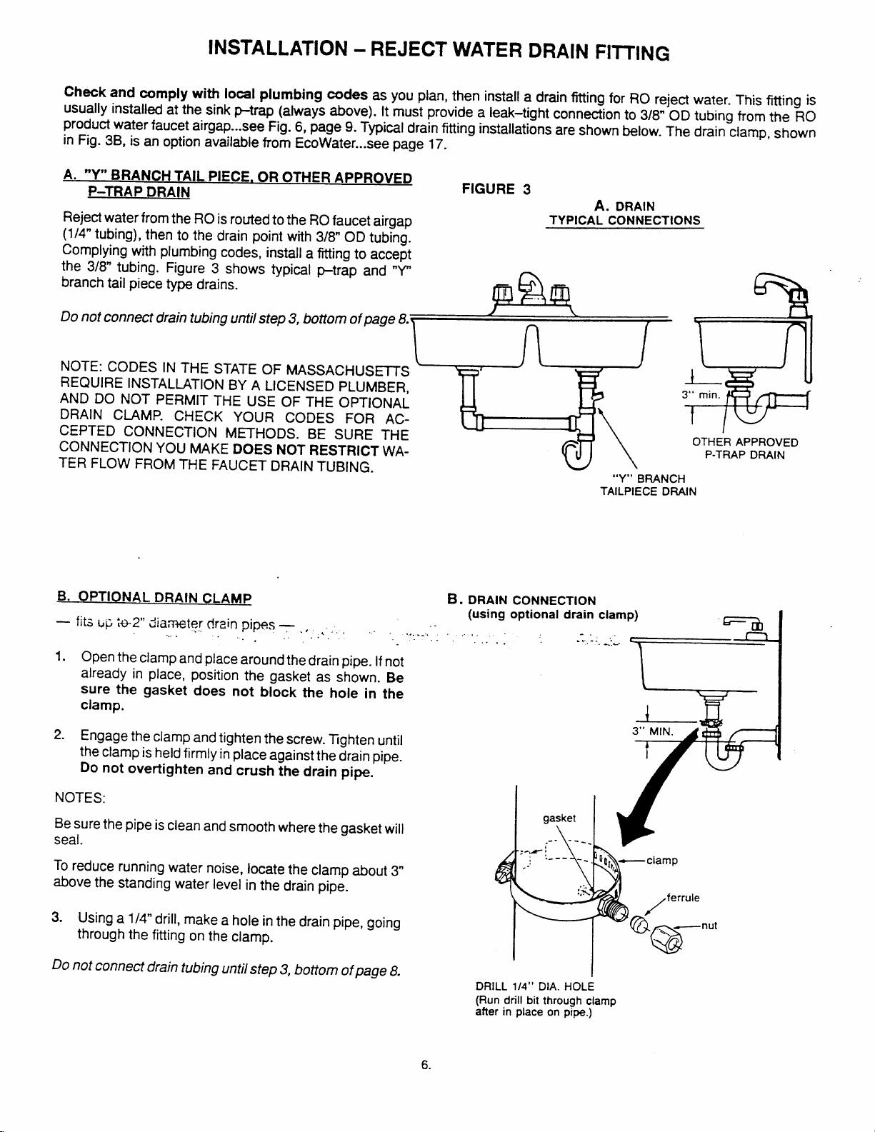
INSTALLATION - REJECT WATER DRAIN FITTING
Check and comply with local plumbing codes as you plan, then install a drain fitting for RO reject water. This f~ing is
usually installed at the sink ~rap (always above). It must provide a leak-tight connection to 3/8” 00 tubing from the RO
product water faucet airgap...see Fig. 6, page 9. Typical drain fitting installations are shown below. The drain clamp, shown
in Fig. 3B, is an option available from EcoWater...see page 17.
A. “Y” BRANCH TAIL PIECE. OR OTHER APPROVED
P-TRAP DRAIN
Reject water from the RO is routed to the RO faucet airgap
(1/4” tubing), then to the drain point with 3/8” OD tubing.
Complying with plumbing codes, install a fitting to accept
the 3/8” tubing. Figure 3 shows typical &trap and “Y”
branch tail piece type drains.
Do not connect drain tubing until step 3, bottom of page 8.\
NOTE: CODES IN THE STATE OF MASSACHUS~S
REQUIRE INSTALLATION BY A LICENSED PLUMBER,
AND DO NOT PERMIT THE USE OF THE OPTIONAL
DRAIN ClAMP. CHECK YOUR CODES FOR ACCEPTED CONNECTION METHODS. BE SURE THE
CONNECTION YOU MAKE DOES NOT RESTRICT WATER FLOW FROM THE FAUCET DRAIN TUBING.
FIGURE 3
DRAIN
TYPICAL CONNECTIONS
(
A.
R
(
(7
)
w
3“ min.
OTHER APPROVED
P-TRAP DRAIN
“Y” BRANCH
TAILPIECE DRAIN
B. OPTIONAL DRAIN CLAMP
—fit3~p t~2’’diawt~r drainpipes-, , ,,, .. . ‘- ,. .
....
1.
Open the clamp and place around the drain pipe. If not
. .
.. . .,
. . ..
~. DRAIN CONNECTION
(using optional drain clamp)
.......
. .. . .
already in place, position the gasket as shown. Be
sure the gasket does not block the hole in the
clamp.
2. Engage the clamp and tighten the screw. Tghten until
the clamp is held firmly in place against the drain pipe.
Do not overtighten and crush the drain pipe.
NOTES:
Be sure the pipe is clean and smooth where the gasket will
seal.
To reduce running water noise, locate the clamp about 3“
above the standing water level in the drain pipe.
3. Using a 1/4” drill, make a hole in the drain pipe, going
through the ftiing on the clamp.
Do not connect drain tubing until step 3, bottom of page 8.
DRiLL 114” DiA. HOLE
(Run dnii bit through ciamp
after in piace on pipe.)
gasket
,---- --
\
.,-.
-.
“=-l~:- ~
—ciamp
04}/
ferruie
i
/
G@
—nut
\
@
6.
Page 7

INSTALL THE FAUCET
(Install Standard Faucet, page 8)
Select one of the following places to install the faucet. Be
sure there’s room underneath so you can make the needed connections.
NOTE: Looking at Fig. 4D, be sure the faucet base
flat against the sutiace, at the selected location, so
fit
the
gasket will seal.
—
in an existing sink spray attachment hoie.
—
Drill a hole in the sink top.
—
Drill a hole in the countertop, next to the sink.
1.
If drilling is needed, make a 1-1/8” to 1–1/4” dia. hole.
Be sure to use proper procedures for drilling porcelain or stainless steel.
2.
Place plumbers putty around the drilled hole.
3.
Looking at Fig. 4A, insert a screw into the NON-
SLOITED base mounting hole. Turn a special nut a
few turns onto the screw.
4.
Position the base gasket over the mounting hole. Set
the base on the gasket, routing the leadwire through
the mounting hole. Holding the special nut under the
sink with 1 finger, tighten the screw until just snug.
Turn the remaining special nut a few turns onto the
5.
other screw. Position the screw in the slotted base
mounting hole, and tighten until snug. Carefully
tighten both screws until the base is held firmly in
place. Do not overtighten and break the base.
NOTE: if the faucet is unassembled. slide the lever over
the small cylindrical nut. Then, push or turn the spout into
the faucet body.
6.. ,4ssernNe the top gasket, top faucet base, and hex nut
~.~:~ :~~ f&@ ~+j!?....
snug. Any other faucet parts included are not used.
7. Using the washer, Fig. 4D, turn the tubing adaptor
onto the faucet stud and tighten securely.
8. Take the 27 length of 3/8” tubing and push 1 end onto
the 3/8” faucet barb ftiing...Fig. 4D.
.+ L”. L
~i~-
“.<C. T!2h+eP the .n[~t
will
Until
lever .
9
\ , / ~opg-
---
@
<.
.-.
G.
.-.
(
~
H hex nut
faucet
topgasket
. .
- ..
c.
B.
gasket
D.
M
1-1/4” hole
LOCATE BASE OVER
HOLE AS StlOWN
II
9. Move the RO system into position, under the sink.
Referring to page 9, hang the system on cabinet wall,
or lay on the floor surface, as desired.
10. Route the 1/4” tubing (marked “1/4 barb on faucet”),
and the 3/& tubing (marked “faucet”), from the bot-
tom, up through the mounting hole and faucet base.
Connect to the faucet as follows...see Fig. 4D:
a. Push the end of the 1/4” tubing onto the 1/4” barb on
the faucet.
b. Using the tubing adaptor nut, fasten the 3/8” tubing
to the tubing adaptor, and tighten the nut.
11.
Lower the faucet assembly and lock into place on the
faucet base.
faucet base
leadwire
\
Page 8

INSTALL STANDARD FAUCET
Select 1 of the following places to install the faucet. Be
sure there’s room underneath so you can make the needed connections.
—
—
—
1.
2.
NOTE: If the faucet is unassembled, slide the lever over
the cylindrical nut. Then, push or turn the spout into the
faucet body.
3.
4.
5.
6.
7.
8.
n
L“.
Note: For ease of service and maintenance, keep tubing
lengths long enough so removal of the RO system from under the sink is possible.
existing sink spray attachment hole.
In an
Drill a hole in the sink top.
Drill a hole in the countertop, next to the sink.
If drilling is needed, make a 1” dia. (minimum) hole.
Place plumbers putty around the drilled hole.
Slide the chrome washer and rubber washer, in that
order, onto the faucet stud.
Take the 27 length of 3/8 tubing and push 1 end onto
the 3/8” faucet barb f~ing.
Move the RO system into position, under the sink
(Referring to page 9, hang the system on cabinet wall,
or lay on the floor surface, as desired.) Route the 1/4”
tubing (marked “1/4 bati on faucet”), from the bottom, up through the faucet mounting hole. Push the
end onto the 1/4” barb ftiing.
Work tubing and the faucet stud down, into the mount-
ing hole.
On the underside of the sink or countertop, install the
plastic bushing, flat washer, and hex nut. Slide the
large steel washer in place, between the bushing and
the bottom of the sink or countertop. Then, tighten the
hex nut securely.
Using the washer, turn the tubing adaptor onto the
faucet stud and tighten securely.
u~x.x?”. he 3/8 tubing (marked “faucet”) from th’~ “ “
RO, to the tubing adaptor installed in step 8. Tighten
the tubing adaptor nut securely.
FIGURE 5
..
/
lever
chrome washer
rubber washer
3i8° barb ~
kit
QQbj
/\
. .
m
,\, ~
----
%
nut
spout
~ faucet
1/4” barb
\\
.
CONNECT WATER SUPPLY, FAUCET DRAIN TUBING, and
ELECTRONICS, if applicable
1. Connect “water supply” tubing, Fig. 2 and 6: A
length of 3/8” tubing (marked “water supply”) is attached
to the RO inlet. A separate length of 1/4” tubing and a 3/8”
by 1/4” reducing union are included to make this connec-
tion.
A. Connect the 1/4” tubing to the feed water supply fitting,
installed on page 5. Connect the tubing as applies (Fig. 2A
or 2B) and tighten the nut securely.
B. Standard Faucet Model: Connect the 1/4” tubing to
the 3/8” tubing coming from the RO (marked “water sup-
using the tubing reducing union. Be sure to use tub
ply”),
ing inserts at each connection.
C. Electronic Faucet Models: Using the tubing reducing
union, connect the 3/8 tubing from the RO (marked “water supply”), to the bottom, feed side of the electronic
box. Cut a short piece (3” to 5“) of 1/4” tubing from the
length, installed in A above, to use between the reducing
union and electronic box.
2. Electronic Faucet Models: Referring to Fig. 6, cut the
product water tubing as typically shown, and connect to
the top and bottom of the electronic box, product side.
Again, be sure to use tubing inserts at each connection.
8.
Page 9

3. All Models: Run the 3/8” tubing from the 3/8” faucet
barb, to the drain fitting installed on page 6. Keep this tub back cover and, looking at Fig. 6, fasten the battery con-
ing run as straight as possible, without loops, dips or nector to the battery pack (be sure batteries are installed
/ow+Pots. Cut the tubing as needed and fasten to the
drain fitting (Fig. 3A or 3B), securing as required. replace the back cover.
4. All Models: Run
ting on the RO module, to the shutoff valve at the top of the
storage tank.
‘,
3
T
b
i
\
a iength of 3/8” tubing from the tee fit-
SHUTOFF VALVE
—
\
TANK
2“ (MINIMUM CLEARANCE
FOR CHANGING CARTRIDGES)
L
5. Electronic Faucet Models: Remove the electronic box
correctly). Put the battery pack in the electronic box and
Fasten the electronic box leadwire to the faucet base lead-
wire... Fig. 6.
INSTALL RO ASSEMBLY AND STORAGE TANK
1.
Hold the RO assembly up to the wall where you will
install it. Position and mark locations for the mounting
screws and hanger
2. Fasten the hanger washers to the wall surface. Two
~
wood screws are included for fastening to a wood surface. Provide other screws as needed.
3. Hang the RO assembly on the washers.
4. Move both the RO assembly and tank into place. Set
the tank on the floor surface and install the fittings as
shown. Use teflon tape on fitting threads.
washers.
. .
TYPICAL INSTALLATION
. . .
1
AL
“am~ “‘“
supply /
%r-il-ils V21UP
--””. - .- .-
Note: On standard faucet models,
disreuard the electronic box. but “=, \ ‘,Mmule
conn&t all tubing betweenthe&me —;__
points.
/
‘T
~
..
f
.—-
l-l
.-..
-.. .
-m)
●Electronic
Ill Ill J*-n-
teodll I II
. -J
)
Tank
“1
Faucet
/
JiL
//
IWII ~. -~
\
tubing
reoucerumon,
348”x 1/4”
FIGURE 6
Faucet modelsonly.
al
1) Rr7A~
/~
lNLkT
ilnnl
“Battery
holder
Shutoff
Assembly
[ ....–J
9.
UY
lEFILTER
PF
POSTFILTER
Page 10

~ANITiZING THE RO SYSTEM
INSTALLATION
REFER TO PAGES 12 AND 16.
Sanitizing is recommended upon installation of the RO
system, and after servicing inner parts. IT IS IMPORTANT
FOR THE SERVICE PERSON TO
WHILE HANDLING INNER PARTS OF THE SYSTEM.
CAUTION: BE SURE TO REMOVE ALL CARTRIDGES,
AS FOLLOWS, BEFORE SANITIZING. CHLORINE WILL
DESTROY THE CARTRIDGES.
1. BE SURE WATER SUPPLY TO THE RO IS TURNED
OFF, AND THE RO FAUCET IS OPEN.
2. Remove the u-pin and pull the inlet cover, o-ring and RO
cartridge from the RO housing. PLACE THE CAFITRIDGE
IN A CLEAN PLASTIC BAG.
3. Replace the inlet cover, with o-ring, and re-insert the
u-pin.
4. Remove the POSTFILTER sump, turning to the left. Take
the cartridge from the sump and place in the plastic bag.
Replace the sump and TIGHTEN SECURELY.
HAVE CLEAN HANDS
5. Remove the PREFILTER sump and cartridge. Also place
this cartridge in the clean bag.
6. If needed, flush the prefilter sump with fresh water. Then,
fill with water to about 1” from the top. Add 1.0 oz. of
chlorine (ordinary 5.25%0household bieach... iilexex.Clorox,
etc.) and mix in the water. DO NOT ADD CHLORINE
FIRST. Concentrated, it will attack plastics.
7. Carefully replace the sump, on the prefiiter head, and
tighten securely.
8. Open the tank shutoff valve, and the water supply to the
RO. Open the RO faucet, locking the lever upward, against
the spout.
9. Allow water to circulate through the system until the
bieach odor is gone.
10. Turn off the water suppiy to the RO. Ciose the RO faucet
afier water fiow stops.
11. Repeat steps 1-5 and 7, oniy replace ali cartridges. BE
SURE YOUR HANDS ARE CLEAN.
PRESSURE TESTING
DO THE SANITIZING PROCEDURES ABOVE BEFORE PRESSURE TESTING.
1. Open the water suppiy shutoff vaive, page 5.
. .
2.Open the main water suppiy vaive. Open faucets to let tubing connections for any water leaks. Correct leaks
air out of the pipes and ciose when water runs smooth.
5. IMPORTANT PURGING INSTRUCTIONS: The RO cartridge contains a food grade presewative that you shouid ciean
from it before using the system. The presemative wiii give product water an unpleasant taste and odor. After the storage
tank has fiiied (takes about 12 hours), open the system faucet until the tank is empty. Aiiow the tank to fiii again for
12 hours, then open the faucet and empty. After 4 purgings, the system is ready to make product water for your use.
..
. .“.,..
3.Open the water shut-off valve on the storage tank. .
‘- 4.in about
system. At that time, carefuiiy cll~c~ aii iitiings end
if any are found.
4 hours, pressure wiii s?art :C bu~ld ;: the !?0
10.
Page 11

HOW THE RO DRINKING WATER SYSTEM WORKS
PREFILTER
Water from the cold supply pipe enters the RO assembly
prefilter first (Fig. 6).
ERO 200— The prefiiter has a 5
micron replaceable sedi-
ment cartridge. It removes sand, silt, dirt and other
sediments that may be in the water supply. Filtered, clean
flOWS from the prefiiter, to the RO membrane
water
cartridge.
300-
ERO
The prefilter is a replaceable sediment cartridge with activated carbon in its composition. The cartridge (1 to 2 micron) removes sand, silt, dirt, other sediments, and
Up to 2.0 ppm of chlorine from the feed water
(CHLORINE DESTROYS THE ERO 300 RO MEMBRANE). Filtered, clean,
Chlorine-free water ftows from
the prefilter, to the R() membrane cartridge. IMPORTANT:
SEE PREFILTER MAINTENANCE, PAGE 12.
REVERSE OSMOSIS
(RO) CARTRIDGE
The cartridge, inside the RO housing, includes a tightly
wound, speciaJ membrane. Water is forced through the
cartridge where the membrane removes the dissolved
solids and organic matter. High quality product water exits the RO housing and goes to the storage tank or to the
postfilter. Reject water, with the dissolved solids and
organic matter, ieaves the housing and goes to the drain
through the 1/4” tubing. .
The electronic faucet provides a buiit-in
ter.
As water is taken from the faucet, the indicator
water quality tes-
iights show how the RO system is operating to provide high
quaiity drinking water.
FLASHING GREEN LIGHT-The RO system is giving you
high quaiity drinking water.
FLASHING RED “FILT” LIGHT - The prefiiter and postfiiter cartridges need repiacing. This occurs after 6 months,
or 900 gaiions of product water use. Also replace the
controi box batteries ...see page 13.
FLASHING AMBER “ROY’ LIGHT – The RO cartridge no
ionger removes at ieast 75°/0 of the TDS from the suppiy
water and needs replacement.
NOTE: Disregard initial or short periods of the fiashing
“RO” iight.
SHUT-OFF ASSEMBLY
To conserve water, the drinking water system has an
automatic shut-off assembiy. When the storage tank has
filied to capacity, and the drinking water faucet is ciosed,
pressure cioses the shutdf. Water fiow to the RO housing is shut off untii drinking water is used again, and
pressure drops in the RO system.
CHECK VALVE
STORAGE TANK
The storage tank huids up to 2’.1 gaiions Ui pic)tiuc~ waier.
A diaphragm inside
when the tank is fuii) for fast fiow to the faucet when
30 psi
the tank keeps water pressurized (to
drinking water is needed. A 10 gaiion tank is an avaiiabie
option.
POSTFILTER
After ieaving the storage tank, but before going to the
faucet, product water goes through the postfiiter. The
postfiiter aiso has the activated carbon type sediment
filter. Any remaining tastes, odors or sediments are removed from the product water. Taste-free, odor free, ciean,
high quaiity drinking water fiows through the tubing to the
faucet.
FAUCET AND ELECTRONICS
The sink or countertop faucet vends the drinking water
when opened. it has a hand operated, spring-loaded
closed lever to prevent waste. You can also keep the faucet open by pushing upward on the lever and locking it
against the faucet spout.
To compiy with piumbing codes, an
the faucet drain water connection.
air-gap is buiit into
..
A check vaive (Fig. 8 and 9) is buiit into 1 end of the RO
hO!JS@, urder the tee fitting. The Check VaiVe prevents
ti&~kWiliU ~iOW 01 PICJJtiCt Wa;~~ ;iCi,, L, 4G d.=- ‘‘.’- - “-’rage tank.
a
.
..
A backward fiow couid rupture the FIO membrane.
FLOW CONTROL
The fiow controi (see Fig. 9, page 13) reguiates flow,
through the RO cartridge, to the required rate to get the de-
sired quaiity of product water. The controi is located in the
eibow fitting, at the RO housing drain port. A smali, con~
shaped screen fits over the front end of the flow control to
help prevent piugging with drain water sediments.
This reverse osmosis system contains a replaceable
treatment component critical for effective removai of
totai dissolved soiids. The water shouid be tested
periodically to verify the system is performing
satisfactorily.
11
Page 12

MAINTENANCE
(Also see Filter-Cartridae Redacement Guide on Paqe14)
To keep the drinking water system operating and making
high quality water, the prefilter cafiridge, RO cartridge. and
postfilter catiridge need replacing at certain intema!s.
When replacing patis, simply lift the RO assembly from the
mounting washers and lay on the floor sc you can easily
work on it. You can also remove the RO housing by pulling
out of mounting ,clamps.
CAUTION: BEFORE DISCONNECTING ANY PARTS,
CLOSE THE SHUTOFF VALVE ON THE STORAGE
TANK, CLOSE THE WATER SUPPLY SADDLE VALVE,
AND OPEN THE DRINKING WATER FAUCET.
seconds to 1 minute for pressure to relieve through the
system.
PREFILTER AND POSTFILTER CARTRIDGE
Allow 30
ERO 200- After a time, the sediment prefilter cartridge
begins to plug with sediments and water cannot get
through it as fast. You may notice a slower making of
quality product water. When this happens, anew sediment
cartridge is needed. Also replace the postfilter cartridge.
ERO 300 – YOUmust replace the prefilter cafiridge often
to protect the RO membrane from being destroyed by
ch/orine andior from plugging with sediments that are in
the water supply. If the water supply contains both chlorine
and sediments. replace the prefilter cartridge at least every
6 months, or more often if it begins to-plug with sediments.
If the water has sediments only, WITH NO CHLORINE,
then read RO 200 above. Also replace the postfilter cartridge.
ELECTRONIC MODELS – To signal correct replacement
intewal,
after 6 months. or 900 gallons of product water use, whichever
At the same time. replace the postfilter cartridge and the
batteries in the control box. Replacing the batteries resets
the 6 month or 900 gallon period, and assures proper
operation of the “ROWindicator light (see page 13).
REPLACING CARTRIDGES...Tum the sump out of the
filter head. BE CAREFUL... THE SUMP IS FULL OF WATER.
sump with fresh water and insert the new cartridge.
SURE THE lARGE O-RING IS IN PLACE ON THE TOP
OF THE SUMP, AND LUBRICATED (USE LUBRICANT
APPROVED FOR USE ON POTABLE WATER SUP-
PLIES). Turn the sump into the head and tighten securely.
Repeat this procedure on the other filter.
RO CARTRIDGE
The life of the RO cartridge depends mostly on the pH of
properly treated feed water... see pages 3 and 4.
the red “FIL~ indicator light will begin to flash
occurs first.
Remove and discard the inner cartridge. Flush the
. .
BE
11
!-/
1’
1
,:,
I
l::! ~
Ii .,:
TO REMOVE SUMP
TURN
THIS WAY
SUMP
w
The higher the pt-i, the shorter the cartridge life. For example, if feed water pH is from 6.8 to 7.7, the cartridge
last for well over 1 year. However, cartridge life maybe as
short as 6 months if the pH is as high
higher pH weakens the cartridge membrane and makes
pin hole leaks.
It’s time to replace the RO cartridge when the quality and/
or prockctim’”rate of product “~ate~-dIUK [.!’rst replace
prefilter and postfilter cartridge). Product water may begin
to taste different or even bad, indicating solids and organ-
ics are getting through the cartridge.
NOTE: When replacing the RO cartridge, also install the
new flow control (included). The prefilter and postfilter
cartridge should also be replaced,
ELECTRONIC MODELS - It’s time to replace the RO
cartridge when the amber “RO” light on the faucet base
begins to flash continually whiie RO water is taken from the
faucet (see page 11).
TO REPIACE THE CARTRIDGE..<
1.
Turn off the water suppiy (see the preceding caution
note, above ieft column).
2.
Remove the inlet cover from the housing. (Remove
the retainer ring and puli the u-pin.)
3.
Use a pliers to pull the cartridge from the housing.
4.
instali the new cartridge and repiace the inlet cover
(iubricate o-ring if needed).
Insert the u-pin and instali the retainer ring.
5.
as 8.5 or 11.0. The
may
IL.
Page 13

MAINTENANCE
6. Remove the old flow control and replace with the new
control included with the RO cartridge (see below).
7. PURGE THE CARTRIDGE AS INSTRUCTED ON
PAGE 10.
BAITERIES IN ELECTRONIC CONTROL BOX
Always replace the 4, “AA’” alkaline batteries in the control
box when changing the pre and postfilter ca~ridges. Good
batteries are needed to assure proper indicator light
operation. Weak batteries may give a false indicatio~.
Changing the batteries also resets the 6 month or 900
gallon period.
FLOW CONTROL AND SCREEN
The flow control is vital for proper operation of the RO
cartridge. The control must keep water fiow through the
cartridge at the proper rate to obtain the best quality
product water.
When servicing the RO, it’s good practice to check the fiow
control (and black tubing to it) to make sure the small tube
and surrounding surfaces are clean and unrestricted. A
small, coneshaped screen (Fig. 9) is located in front of the
flow control to help keep it clean. !f the flow control should
plug with foreign particles, the RO cartridge cannot
discharge minerals or impurities to the drain. it would only
take a short time for the cartridge to plug, making it
useless.
CAUTION: To install the screen, place the cone end into
the elbow fitting. Then, carefully push it in using the 1/4”
tubing as a tool. Do not force in after you feel resistance.
Visually check to be sure it is properly positioned.
.,
s..’.”’
.. ...
FIGURE 9
compression
nut
\
r
c}
Illf
..
screen
TO
DRAIN
1/4”
ontrol
tubing
When installing the flow control, tighten the nut by”hand.
then another 1
OVERTIGHTEN AND DISTORT OR CRUSH THE
TUBING AND FLOW CONTROL.
i4 to 1/2 turn with a pliers. DO NOT
13.
Page 14

FILTER-CARTRIDGE REPLACEMENT GUIDE
MODEL ERO 200
AT LEAST EVERY 6 MONTHS
– Replace prefilter sediment cartridge and postfilter
carbon cartridge.
– Make replacements indicated if any of the
following occur before the 6 months -
CHLORINE (OR OTHER) TASTE AND/OR ODOR
– Replace postfilter carbon cartridge
– If taste & odor persists, also replace prefilter
sediment cadridge, RO cartridge, flow control and
screen.
SLOW PRODUCTION RATE
– Replace prefilter sediment cartridge
– If rate does not increase, replace postfilter carbon
cartridge, RO cartridge, flow control and screen.
HIGH TDS
– Replace prefilter sediment cartridge, postfilter carbon
cartridge, RO cartridge, flow control and screen.
MODEL ERO 300
AT LEAST EVERY 6 MONTHS
- Replace
cartridges.
prefilter and postfilter sediment-carbon
– Make replacements indicated if any of the
following occur before the 6 months –
CHLORINE TASTE AND/OR ODOR
- Replace prefiiter cartridge, postfilter cartridge, RO
cartridge, flow control and screen.
OTHER
–
TASTE AND/OR ODOR
Replace postfilter cartridge
– If taste & odor persists, replace prefilter cartridge,
RO cartridge, flow control and screen.
SLOW PRODUCTION
Replace prefiiter cartridge
–
RATE
– If rate does not increase, replace postfilter cartridge,
RO cartridge, flow control and screen.
HIGH TDS
– Replace prefilter cartridge, postfilter cartridge, RO
cartridge, flow control and screen.
ELECTRONIC MODELS
..
fl.”r !.E.~.5T 5\lEpy 5 *.V251THCOR qoo G,4L1.cyvS ~~ pp M1.’ii k~ U,WT
— ------------- “ “ “
Replace the prefilter cartridge, postfilter cartridge, and batteries in the electronic box.
WHEN THE AMBER “RO” LIGHT FLASHES -
Replace the RO cartridge, flow control and screen.
RED “FIL~ LIGHT FLASHES –
14.
Page 15

..
Page 16

REPAIR PARTS
SADDLE VALVE
‘0 ‘-T---
ELEC.BOX
42
/
M! ~z”
DRAIN CLAMP
\
4
46
48
DRAIN WATER
TO FAUCET
Y
.-
,.-
<~’
45
6
d @-l ‘“
Iw
r’~ ,
1
I
c.=
\
.
\
“’’-_=””’ – 28
29
\
.
\
\
1
/’ ,’
)
/
.’
8
16,
Page 17

REPAIR PARTS
KEY ~
NO.
II
[2
3 [ 7112248 I Top, Faucet Base+
I
4 ~ 0900713 I Screw, %32x 1-3/8 (2) +
5
I
6
7 7115725 j Nut (2) +
8 I 9003203 / Nut, 3/8” Tubing (8)
9 7131349 ~Insert, 3/8” Tubing (9)
I
10 7115694 I Electronic Box + - incl’sthe following
—
—
—
11
12
13
I
14
15
16
I
17
I
L
18
19 90w801 ! Elbow, 1/8” NPT x 3/8” Tubing (2)
PART I
~ NUMBER /
~ 7095925 ~Faucet
I 7051206 ~Top Gasket+
7115686 i Base, Faucet+ @
7114614 ~Gasket+
1269800 i Spring (not illustrated)
7087477 j Magnet (not illustrated)
7127756
7115822 I Battery Holder ● (batteries not in-
1
7087223 I Screw, #1 O – 16 x 1/2” (4)
7078389 ~Head (2)
7098185 ~
7070323 ! Sediment-carbon Cartridge
7093494 ! Ring, 3- 5/8” I.D. x 3- 7/8 O.D. (2)
7065394 ! Sump (2)
7100770 ] Elbow
I Flow Washer (not illustrated)
eluded)
I
Elbow Assembiy (2)
DESCRIPTION
—-——--.--..-—..—-----.—.-
7112442 ~Valve Top
21 ‘--
r
22 71124WI
7014979 ~Plunger
23
7099296 ]
24
25 7112442 ~Valve Top
I
7030721 ~Screw, #10- 14x 1 – 3/4” (4)
26
—
7133838 I Shutoff Assembly- incls. 21 through 26
—
0020218 Tubing, 1/4” - order length needed
7105160 I Tee, 1/8” NPT x 3/8” Tubing
27
~Valve Center Body
Diaphragm (2)
KEY
NO.
28
29 I 7101726 ~Tank Shutoff Valve
30 ~ 7112523 ] Clip (2)
31 I 9006029 i
32 I 7112492 I Bracket
33
34 j 7048041
35
36 1289000
—
37 I 7030438 I RO Housiny includes 34,35 &36
38 9016001 RO Cartridge incls. 43 &44 ERO 200
39
40 ~ 1269800
41 I 7043554 I Tee, 3/8” Tubing
42
43 I 7095030 Cone Screen
44 7167764 I Flow Control,
45
46 7122798
.... ... . .___ .. . . .
, ~?
48
I
49
50 7056565
51 / 7131331
I
– I 9041700 Hanger Washer (2) (not illustrated)
—
—
—
PART ‘
; NUMBER , DESCRIPTION
7077464 ‘Tank,
7095983
9033600 I Sediment Cartridge ERO 200
I
~ 7070323 ~Sediment<atin Cartridge ERO 300
: 7093509 O-ring, 1 – 19f32° LD. x 2“ O.D.
, 0900288 , Retainer (not illustrated)
\ 7096086
9000702 Check Ball
I
9004504 [ Elbow, 1/8” NPT x 1/4”Tubing
I
9003204 Nut, 1/4” Tubing
I
7g797Q ?.
!
I
7011272
I
,
7ofYll 44
[ Insert, 1/4” Tubing (3)
9006062 I Woodscrew (2) (not illustrated)
7163396 Small Parts Skin-pack
0010251 Tubing, 3/8” – order length needed
2.1 gal. (standard)
Tank, 10 gal. (optional, not included)
screw (4)
inlet Cover
UPin
RO Cartridge incls. 43 & 44 ERO 300
Spring
1-3/4” long
Drain Clamp@
; [.}k=!q (Yyy @
I Saddle Valve@
Adaptor, 7/16“ -24
Reducing Union @
0 Includes key nos. 2,3,4,6 and 7.
@ Not included with RO - Not allowed in all
local codes).
areas (check you
@ Includes compression nuts-Also use with 1/4”and 3/8” tubing
inserts, key nos 9 and 51.
17
 Loading...