

Page 1
GDT226SILII
ADA
COMPLIANT
GE® ADA Compliant Stainless Steel Interior Dishwasher with Sanitize Cycle
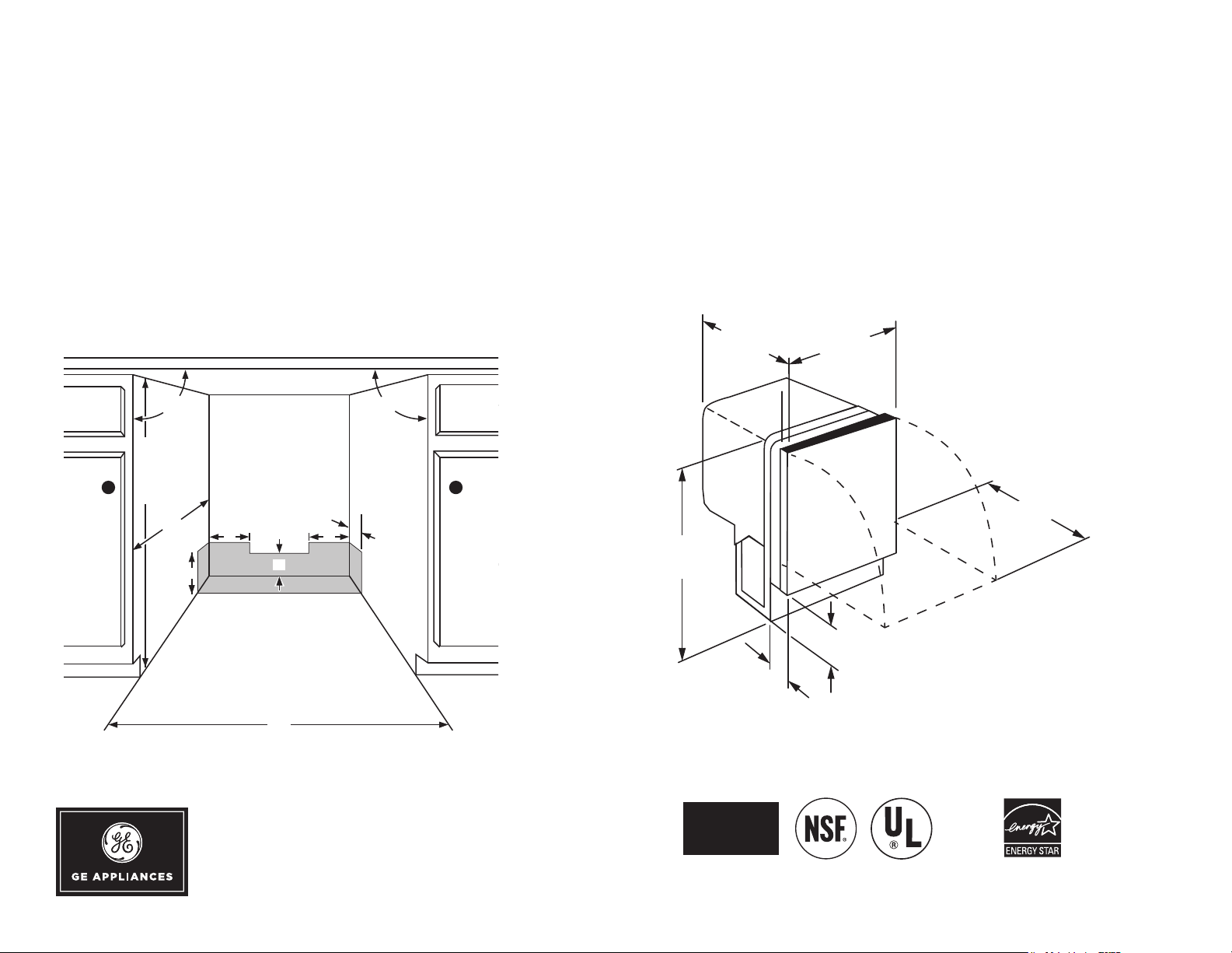
DIMENSIONS AND INSTALLATION INFORMATION (IN INCHES)
ELECTRICAL RATING
Voltage AC..........................................................120
Hertz....................................................................60
Total connected load amperage ........................ 8.9
For use on adequately wired 120-volt, 15-amp circuit having
2-wire service with a separate ground wire. This appliance
must be grounded for safe operation.
23 3/4"
Includes tub trim
90° 90°
23 1/2"
Includes
3/4"
custom panel
32-3/8" min. to
34-3/4" max.
Underside of
countertop to
floor
24"
6"
Electrical, drain and
water supply line
entrances must
be confined to
shaded areas to
avoid interference
with components
5" 5"
4"
24"
For answers to your Monogram, GE Café™, GE Profile™ or GE Appliances
product questions, visit our website at geappliances.com or call
GE Answer Center® Service, 800.626.2000.
3"
32 1/4" min
34 5/8" max
4"
Toekick height:
4" min
8 3/8" max
Depending on install.
Listed by
Underwriters
Laboratories
23"
As an ENERGY STAR®
partner, GE has determined
that this product meets the
ENERGY STAR guidelines
for energy efficiency.
Specification Revised 2/21
Page 2
GDT226SILII
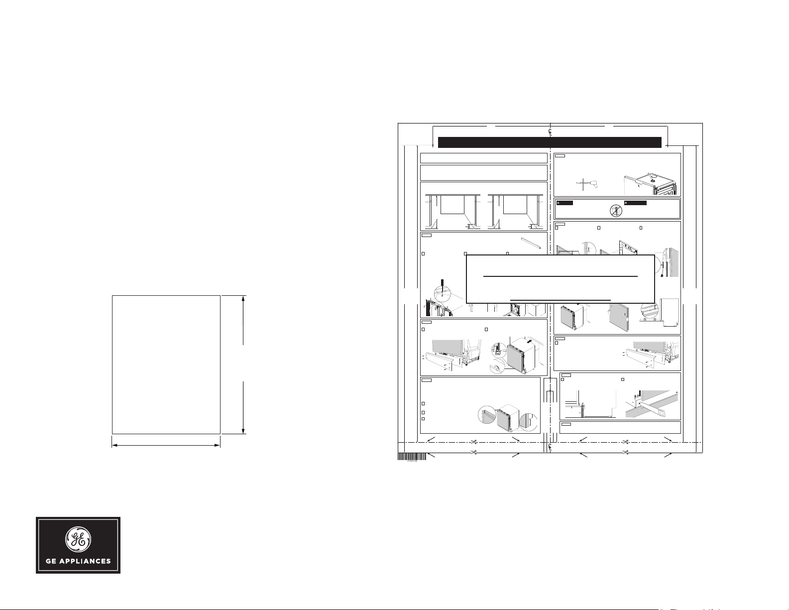
CUSTOM PANEL
Top Screws
1/8"
Upper Overhang
bracket use)
Lower Overhang
GE® ADA Compliant Stainless Steel Interior Dishwasher with Sanitize Cycle
DIMENSIONS AND INSTALLATION INFORMATION (IN INCHES)
All units ship with complete full-size panel template. The
template can be ordered from parts - WD02X29298.
IMPORTANT: TO ENSURE OPTIMUM
DOOR BALANCE PERFORMANCE, THE
CUSTOM PANEL MUST NOT WEIGH
MORE THAN 17.6 LBS.
A custom handle must be installed onto the
custom panel.
29 13/16"
(75.7) min
26 1/4" min
30 1/4"
30 5/8" max
(76.8) max
23 3/4" (60.3)
3/4” Custom Panel Template and Installation Instructions
The custom panel should be sized to your installation situation.
It is highly recommended that the custom panel be attached before nal installation of the dishwasher.
Use this Template to locate the mounting screws and bracket on the custom panel.
IMPORTANT
• A custom handle may be installed or a pocket handle opening
may be cut into the custom panel.
• These instruction are for installing the custom panel only. Follow
the product Installation Instructions for installing the dishwasher.
DISHWASHER ENCLOSURE
• This dishwasher may be installed into an opening that is min.
32-1/2” tall to meet the Americans with Disabilities Act (ADA).
ADA Compliant
Min. Opening
32-1/2”
to 34”
total
opening
height
STEP 1
ATTACH INFILL BRACKET (FOR STANDARD ENCLOSURE OPENINGS GREATER THAN 34" TALL)
IMPORTANT: Skip this step if enclosure opening height is less than 34" tall.
• The inll bracket may be installed as a cosmetic feature to ll the empty space visible for cabinets with
cavity height of 34” or greater.
• Installation of the infill bracket is not needed for cabinets with ADA heights.
NOTE: A decorative wood panel may be attached to the face of the inll bracket to match cabinetry.
Remove upper mounting brackets
1
and plastic plugs
• Open the door.
• Remove the upper mounting brackets
from the top of the dishwasher and
re-install on the sides following the
dishwasher Installation Instructions.
• Push a small screwdriver down
19-9/16"
18-3/4"
(For
(For
overhang
overhang
between
between
2-1/8"
1-5/16"
and
and
2-15/16")
2-1/8")
STEP 2
IMPORTANT: To protect ooring, place protective material under the dishwasher feet before moving.
Remove toekick and mounting plate
1
• To access the rear leg adjustment pin, remove the toekick
STEP 3
IMPORTANT
• Remove the dishwasher from the enclosure.
• Ensure the custom door panel has the correct specifications to fit the front of the dishwasher.
• Seal the back and sides of the panel with a waterproof vapor barrier (ie: polyurethane). The barrier allows the panel
to withstand moisture (122°F @ 80% RH) and prevents damage to it as the dishwasher operates in a hot and wet
environment.
• If the enclosure opening is more than 32-1/2” tall, the top of the custom panel can overhang the top of the door to match cabinets.
Measure the panel and overhang
1
• Measure the back of custom panel, mark its centerline and
Cut or fold this Template along the appropriate
2
bottom line for the required overhang
Align this Template to the centerline and bottom of
3
the panel and mark pilot holes
• Place the centerline of this Template on the centerline
through
the screw holes, in the top of the
dishwasher, to remove the plastic plugs.
TEMPORARILY STAGE DISHWASHER IN THE ENCLOSURE AND ADJUST LEVELING LEGS
and mounting plate by removing their four screws. Set aside
for re-installation.
REMOVE DISHWASHER FROM ENCLOSURE AND PREPARE THE CUSTOM DOOR PANEL
determine the overhang length from the base of the door.
of the panel, align with bottom, mark out and drill pilot
holes into the back of the custom panel. Ensure pilot
holes are 1/16” wide and 1/2” deep.
USE THIS LINE FOR DOOR OVERHANG FROM 1-5/16” TO 2-1/8”
USE THIS LINE FOR DOOR OVERHANG FROM 2-1/8” TO 2-15/16”
PARTS INCLUDED:
• 4 #8 x 1/2” Phillips truss head stainless steel screws
• 4 #8 x 1-1/2” Phillips truss head
• 1 Inll Bracket
• 1 Slider Bracket
• This dishwasher may also be installed into a standard opening
greater than 34” tall by installing the inll bracket.
4” to 6”
Install the inll bracket
2
• Remove two screws pre-installed
from the inll bracket.
• Use the same screws to attach the
bracket to the top of the appliance.
Do not tighten fully.
For Reference Only
2
Front
legs
Rear leg
adjustment
pin
(Measure for inll
9-1/4" 9-1/4"
STEP 4
INSTALL A CUSTOM HANDLE OR CUT OUT A POCKET HANDLE OPENING INTO THE TOP OF
THE CUSTOM PANEL
IMPORTANT: Handle installation or pocket handle opening cutout must be done before the custom panel is
installed on the dishwasher.
:
Custom Handle Option
• Align handle with adjacent drawer handles.
• Install in the same manner as cabinet handles. Screws must be
countersunk into the panel.
Panel
Custom
Handle
Screws
must be
countersunk
Standard
Opening
34”
to 35”
total
opening
height
4” to 6”
Align and adjust appliance in cabinetry
3
• Push the appliance into the cabinetry.
• Ensure the inll bracket does not hit
the top of the cabinet while pushing.
(Refer to ALIGN APPLIANCE IN
CABINETRY section for more details.)
• Slide the side wings of the bracket
outward to cover the hollow space.
• Hand tighten the two screws.
IMPORTANT: To protect ooring,
place protective material under
1-5/16” to
2-15/16"
5-7/8"
4-7/8"
and Lower
Bracket
overhang
between
2-15/16")
the dishwasher feet before
moving.
5-1/16"
and
and
4-1/16"
Upper
Upper
and Lower
Bracket
Holes
Holes
(For
(For
overhang
between
2-1/8"
1-5/16"
and
and
2-1/8")
Printed in China
Not to Scale
Adjust legs to the installation height
• Adjust the front feet using an adjustable wrench.
• Adjust the rear foot via the back leg adjustment pin using an
Allen wrench.
Adjust
(Measure for all
installations)
into panel
CAUTION
Opening the door will cause the dishwasher to tip forward
when it is not fully installed. When opening the door prior
to the dishwasher being fully installed, hold the top of the
dishwasher securely with one hand and hold the door with
the other hand. Gloves should be worn.
STEP 5
ATTACH CUSTOM DOOR PANEL TO DISHWASHER FRONT
Fix slider bracket and screws to
1
custom panel
• Insert #8 x 1/2” screws through the
top two pilot holes. Fix the slider
bracket to the panel through the
lower pilot holes.
(between panel
and screw head)
Slide the dishwasher into the
4
enclosure
STEP 6
INSTALL THE TOEKICK
Re-install the toekick mounting plate and panel
•
• Re-install the toekick and mounting plate panels that were removed
earlier. If desired, a custom continuous toekick panel can be
installed.
STEP 7
Check the door overhang and its swing range
1
• Door overhang and swing range is relative to height and
depth of toekick panel. Cut back excess panel to ensure
continuous, seamless integration.
Door Panel
STEP 8
IMPORTANT:
• Follow the Installation Instructions, shipped with your dishwasher, to complete the installation.
Hang custom panel onto the door
2
• Close the dishwasher door. Align
and insert the screws in the custom
panel into the bottom slots in the
dishwasher door front.
Adjust placement of the custom panel
5
• Slide the custom panel up to position
it in the desired location. NOTE: If
notched up too far, then slide it all the
way up, remove and begin again.
INSTALL CONTINUOUS TOEKICK (OPTIONAL)
Cut back excess toekick
Toekick
INSTALL THE DISHWASHER INTO THE ENCLOSURE
If the infill bracket was installed, it will need to be adjusted as appropriate to secure the dishwasher.
USE THIS LINE FOR DOOR OVERHANG FROM 1-5/16” TO 2-1/8”
USE THIS LINE FOR DOOR OVERHANG FROM 2-1/8” TO 2-15/16”
Pocket handle
cutout
PRECAUCIÓN
3
6
(repeat on both sides
:
Balance the door
• Check the door balance by opening
and closing the door.
• If the door drops when released,
increase the tension.
• If the door rises when released,
decrease the tension.
Increase
Decrease
Secure the custom panel
• Open the dishwasher door, remove
the four screws and replace with
#8 x 1-1/2” screws to securely attach
the panel into place.
Screw Locations
of the appliance)
Pocket Handle Cutout Opening Option
• Cutout and contour at top of the custom panel as desired for
appearance and feel.
Abrir la puerta hará que el lavavajillas se incline hacia adelante
cuando no se encuentre completamente instalado. Al abrir la puerta
antes de haber instalado completamente el lavavajillas, sostenga
la parte superior del lavavajillas de forma segura con una mano y
sostenga la puerta con la otra mano. Se deberán usar guantes.
Insert into
Bottom Slots
Align and prepare continuous toekick panel (Optional)
2
• Align the toekick to desired position and mark out the
point in which the toekick meets the base of the door
panel. Cut back excess. Attach to cabinetry (optional).
18-3/4"
(For
overhang
between
1-5/16"
and
2-1/8")
31-4000242 Rev 0
11-20 GEA
19-9/16"
overhang
between
2-15/16")
(For
2-1/8"
and
For answers to your Monogram, GE Café™, GE Profile™ or GE Appliances
product questions, visit our website at geappliances.com or call
GE Answer Center® Service, 800.626.2000.
Specification Revised 2/21
Page 3

GDT226SILII
GE® ADA Compliant Stainless Steel Interior Dishwasher with Sanitize Cycle
FEATURES AND BENEFITS
ADA Compliant with Low-Profile Installation – Great for 34"
counter top heights and raised subf loors
3-Level Wash – Expect exceptionally clean table-ready dishes
with powerful wash arms
Autosense Cycle – A beam of light measures soil levels and water
temperature to adjust to the ideal cycle time
Piranha™ hard food disposer with removable filter – To ensure
consistently clean items, this stainless steel blade rotates at 3,600
RPM to pulverize food particles and helps to prevent large particles
from clogging the wash arms
Sanitize option (NSF Certified) – High-temperature rinse sanitizes
and reduces by 99.999% the bacteria found on dishes
dBA 51
Model GDT226SILII – Custom panel
Additional ADA 24" Models – GDT226SGLBB; GDT226SGLWW;
GDT226SSLSS; GDT225SGLBB; GDT225SGLWW; GDT225SSLSS
Specification Revised 2/21
 Loading...