

Page 1
GEAppliances.com
Safety Instructions . . . . . . . . . . .2, 3
Operating Instructions
Automatic Icemaker . . . . . . . . . . . . . . .10
Care and Cleaning . . . . . . . . . . . . .11, 12
Controls . . . . . . . . . . . . . . . . . . . . . . . . . . . .4
Crispers and Pans . . . . . . . . . . . . . . . . . . .7
Freezer . . . . . . . . . . . . . . . . . . . . . . . . . . .8, 9
Replacing the Light Bulbs . . . . . . . . . .13
Shelves and Bins . . . . . . . . . . . . . . . . . . . .6
Water Filter . . . . . . . . . . . . . . . . . . . . . . . . .5
Installation Instructions
Installing the Refrigerator . . . . . .15–19
Installing the Water Line . . . . . . . .28–30
Preparing to Install
the Refrigerator . . . . . . . . . . . . . . . . . . . .14
Removing and Replacing
the Doors (Double Door
Bottom Freezer
Refrigerator Models only) . . . . . . .25–27
Removing and Replacing the
Freezer Drawer . . . . . . . . . . . . . . . .20, 21
Reversing the Door Swing
(Single Door Refrigerator
Models only) . . . . . . . . . . . . . . . . . . .22–25
Troubleshooting Tips . . . . . .31–34
Normal Operating Sounds . . . . . . . . . .31
Owner’s Manual and
Installation Instructions
Models 20, 22 and 23
Congélateur inférieur
Réfrigérateurs
Manuel d’utilisation
et d’installation
La section française commence à la page 43
Congelador inferior
Refrigeradores
Manual del
propietario e
instalación
La sección en español empieza en la página 81
Consumer Support
Consumer Support . . . . . . . .Back Cover
Performance Data Sheet . . . . . . . . . . .41
State of California Water
Treatment Device Certificate . . . . . . .42
Warranty for Canadian
Customers . . . . . . . . . . . . . . . . . . . . . . . . .40
Warranty for U.S. Customers . . . . . . .39
Write the model and serial
numbers here:
Model # ____________________
Serial #______________________
Find these numbers on a label
on the right side, near the top of the
refrigerator compartment.
Refrigerators
200D9366P004 49-60539-1 09-11 GE
Page 2
IMPORTANT SAFETY INFORMATION.
READ ALL INSTRUCTIONS BEFORE USING.
WARNING!
Use this appliance only for its intended purpose as described in this Owner’s Manual.
SAFETY PRECAUTIONS
When using electrical appliances, basic safety precautions should be followed, including the following:
Installation
Instructions
This refrigerator must be properly installed
and located in accordance with the Installation
Instructions before it is used.
Do not allow children to climb, stand or hang
on the shelves in the refrigerator. They could
damage the refrigerator and seriously injure
themselves.
Do not touch the cold surfaces in the freezer
compartment when hands are damp or wet.
Skin may stick to these extremely cold surfaces.
Do not store or use gasoline or other flammable
vapors and liquids in the vicinity of this or any
other appliance.
Keep fingers out of the “pinch point” areas;
clearances between the doors and between
the doors and cabinet are necessarily small.
Be careful closing doors when children are
in the area.
In refrigerators with automatic icemakers,
avoid contact with the moving parts of the
ejector mechanism, or with the heating element
that releases the cubes. Do not place fingers or
hands on the automatic icemaking mechanism
while the refrigerator is plugged in.
Unplug the refrigerator before cleaning and making
repairs.
NOTE: We strongly recommend that any servicing
be performed by a qualified individual.
Setting either or both controls to the Off position
does not remove power to the light circuit.
Do not refreeze frozen foods which have
thawed completely.
DANGER! RISK OF CHILD ENTRAPMENT
PROPER DISPOSAL OF THE REFRIGERATOR
Child entrapment and suffocation are not problems of
the past. Junked or abandoned refrigerators are still
dangerous…even if they will sit for “just a few days.”
If you are getting rid of your old refrigerator, please
follow the instructions below to help prevent
accidents.
Before You Throw Away Your Old
Refrigerator or Freezer:
Take off the doors.
Leave the shelves in place so that children may not
easily climb inside.
USE OF EXTENSION CORDS
Because of potential safety hazards under certain conditions, we strongly recommend against
the use of an extension cord.
However, if you must use an extension cord, it is absolutely necessary that it be a UL-listed (in the United States)
or a CSA certified (in Canada), 3-wire grounding type appliance extension cord having a grounding type plug
Consumer Support Troubleshooting Tips Operating Instructions Safety Instructions
2
and outlet and that the electrical rating of the cord be 15 amperes (minimum) and 120 volts.
Refrigerants
All refrigeration products contain refrigerants,
which under federal law must be removed prior
to product disposal. If you are getting rid of an
old refrigeration product, check with the company
handling the disposal about what to do.
Page 3
GEAppliances.com
WARNING!
HOW TO CONNECT ELECTRICITY
Do not, under any circumstances, cut or remove the third (ground) prong from the power cord.
For personal safety, this appliance must be properly grounded.
The power cord of this appliance is equipped
with a 3-prong (grounding) plug which mates
with a standard 3-prong (grounding) wall outlet to
minimize the possibility of electric shock hazard from
this appliance.
Have the wall outlet and circuit checked by a
qualified electrician to make sure the outlet is
properly grounded.
Where a standard 2-prong wall outlet is encountered,
it is your personal responsibility and obligation to
have it replaced with a properly grounded 3-prong
wall outlet.
The refrigerator should always be plugged into its
own individual electrical outlet which has a voltage
rating that matches the rating plate.
USE OF ADAPTER PLUGS
Adapter plugs are not permitted in Canada.
This provides the best performance and also prevents
overloading house wiring circuits which could cause a
fire hazard from overheated wires.
Never unplug your refrigerator by pulling on the
power cord. Always grip plug firmly and pull straight
out from the outlet.
Repair or replace immediately all power cords that
have become frayed or otherwise damaged. Do not
use a cord that shows cracks or abrasion damage
along its length or at either end.
When moving the refrigerator away from the
wall, be careful not to roll over or damage the
power cord.
Instructions
Installation
READ AND FOLLOW THIS SAFETY INFORMATION CAREFULLY.
SAVE THESE INSTRUCTIONS
Consumer SupportTroubleshooting TipsOperating InstructionsSafety Instructions
3
Page 4

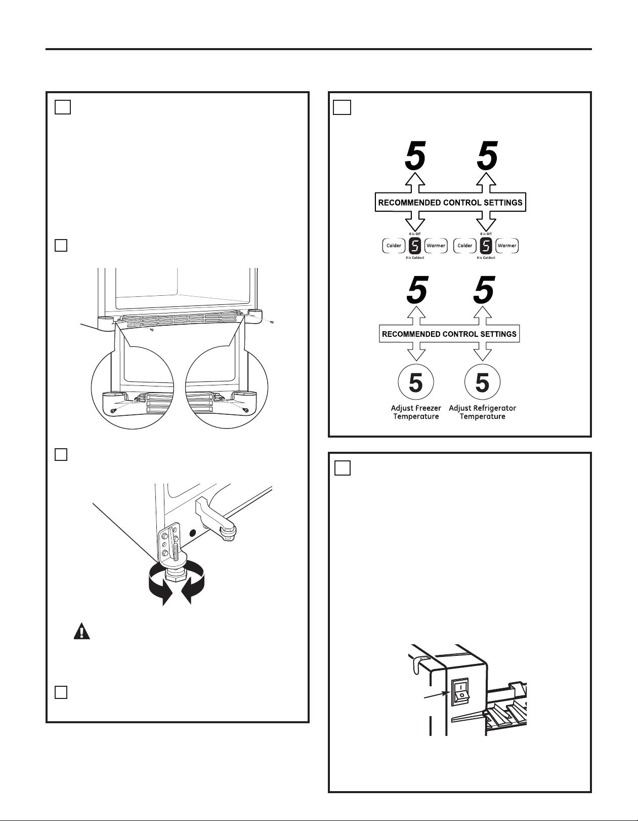
About the controls with temperature settings.
(on some models)
(on some models)
NOTE: The refrigerator is shipped with protective film covering the digital temperature
controls. If this f ilm was not removed during installation, remove it now.
Installation
Instructions
Initially, set the refrigerator control at 5 and the freezer control at 5. Allow 24 hours for
the temperature to stabilize. Several adjustments may be required. Adjust the controls
one increment at a time, and allow 24 hours after each adjustment for the refrigerator
to reach the temperature you have set.
Setting either or both controls to 0 for digital and 0 for the refrigerator control knob
stops cooling in both the refrigerator and freezer compartments, but does not shut
off electrical power to the refrigerator.
Consumer Support Troubleshooting Tips Operating Instructions Safety Instructions
4
Page 5
About the water filter. (on some models) GEAppliances.com
Water Filter Cartridge
The water filter cartridge is located in the
back upper right corner of the refrigerator
compartment.
When to Replace the Filter
The filter cartridge should be replaced
when the flow of water to the icemaker
decreases, or every six months.
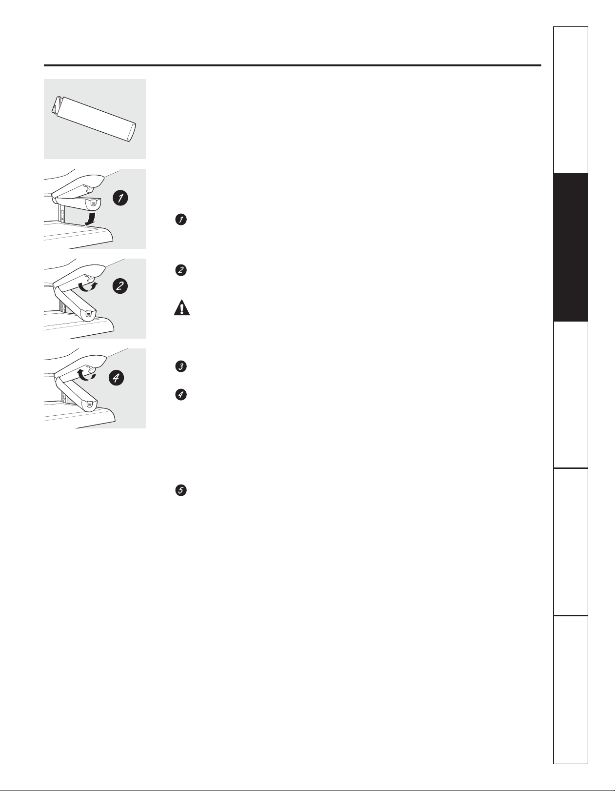
Installing the Filter Cartridge
If you are replacing the cartridge, first
remove the old one. Open the cartridge
cover by pressing in on the tab at the
front and pulling down.
Remove the cartridge by slowly rotating
it counterclockwise. A small amount of
water may drip down.
CAUTION: If air has been
trapped in the system, the filter cartridge may
be ejected as it is removed. Use caution when
removing.
Remove the protective foil from the end
of the cartridge.
Filter Bypass Plug
You must use the filter bypass plug when a
replacement filter cartridge is not available.
The icemaker will not operate without the
filter or filter bypass plug.
Replacement Filters:
To order additional filter cartridges
in the United States, visit our Website,
GEAppliances.com, or call GE Parts and
Accessories, 800.626.2002.
Filter Model GSWF
Customers in Canada should consult
the yellow pages for the nearest Mabe
Service Center.
Instructions
Installation
Lining up the arrow on the cartridge
and the cartridge holder, slowly rotate
the cartridge clockwise until it stops.
When the cartridge is properly installed,
you will feel it “click” as it locks into place.
The grip on the end of the cartridge
should be positioned vertically.
Do not overtighten.
Close the cartridge cover.
Consumer SupportTroubleshooting TipsOperating InstructionsSafety Instructions
5
Page 6
About the shelves and bins.
Not all features are on all models.
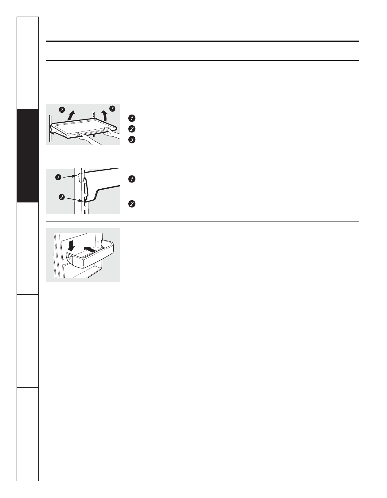
Rearranging the Shelves
Shelves in the refrigerator compartment are adjustable.
Refrigerator Compartment
To remove:
Remove all items from the shelf.
Tilt the shelf up at the front.
Lift the shelf up at the back and bring the
Some models have wire shelves
that can be adjusted in the same
manner.
shelf out.
To replace:
While tilting the shelf up, insert the top
hook at the back of the shelf in a slot
on the track.
Lower the front of the shelf until the
bottom of the shelf locks into place.
Installation
Instructions
Non-Adjustable Shelves on the Door (on some models)
To remove: Lift the shelf straight up; then
pull out.
To replace: Engage the shelf in the molded
supports on the door and push down.
It will lock in place.
Consumer Support Troubleshooting Tips Operating Instructions Safety Instructions
6
Page 7
About the crispers and pans. GEAppliances.com
Not all features are on all models.
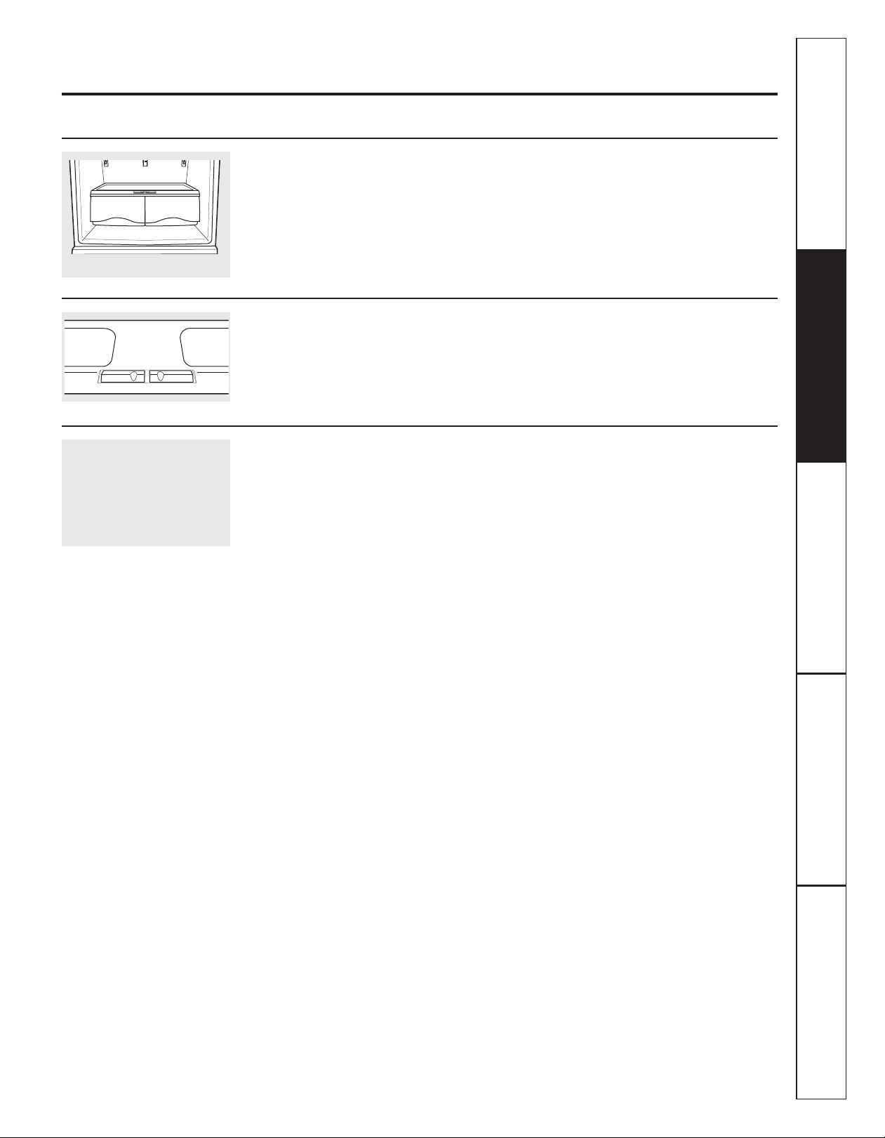
Fruit and Vegetable Crisper
Excess water that may accumulate in the
bottom of the drawers or under the drawers
should be wiped dry.
Adjustable Humidity Crisper (on some models)
Slide the control all the way to the
HIGH setting to provide high humidity
recommended for most vegetables.
Snack Pan (on some models)
This pan can be moved to the most useful
location for your family’s needs.
Slide the control all the way to the LOW
setting to provide lower humidity levels
recommended for most fruits.
To remove, slide the pan out to the stop
position, lift the pan up and past the stop
position and lift it out.
Instructions
Installation
Consumer SupportTroubleshooting TipsOperating InstructionsSafety Instructions
7
Page 8
About the freezer drawer. (on some models)
Not all features are on all models.
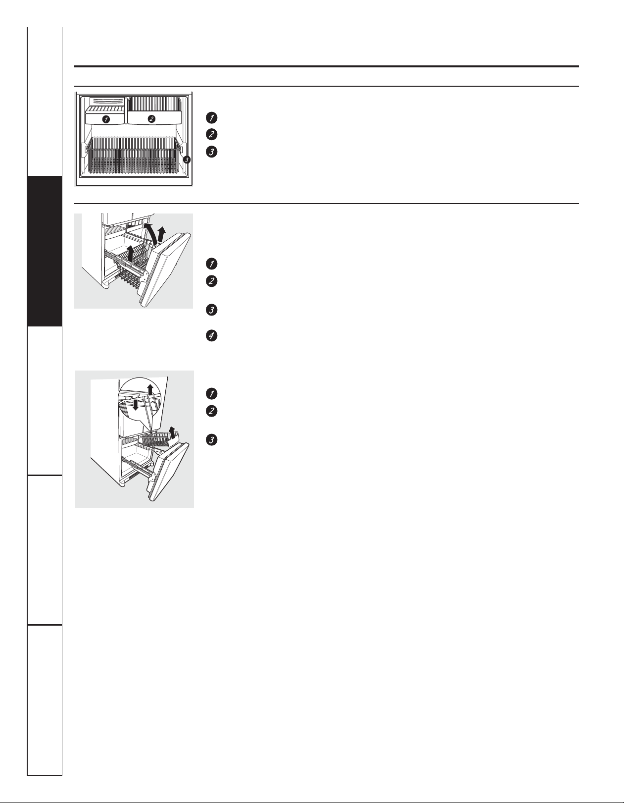
Freezer Shelves and Baskets
Appearance and features may vary
Appearance may vary
Installation
Instructions
A shelf above the ice storage bin
A half-width basket
A deep full-width basket
Basket Removal
To remove the deep full-width basket on
freezer drawer models:
Open the freezer drawer until it stops.
The freezer basket rests on the inside
tabs on the drawer slides.
Lift the basket so that it is out of all
6 slide bracket tabs.
Tilt the basket and lift out of the drawer.
To remove the half-width basket:
Pull the basket out to the stop location.
Lift the basket up at the front to release
it from the stop hooks on each side.
Lift the basket out to remove it from
the sides.
NOTE: Do not fill baskets higher than the rim
of the basket. This may cause baskets to stick
or jam when opening or closing.
When replacing the deep full-width basket:
Tilt the basket back and lower it down
into the drawer. Rotate the basket to a
horizontal position and press it down into
the 6 alignment tabs.
NOTE: Always be sure that the basket is
seated in all 6 slide bracket tabs before
sliding back into the freezer. The basket can
be turned in either direction front to back and
installed into the freezer.
When replacing the basket, make sure that
the basket goes under the stop hooks on
each side.
NOTE: Always be sure to fully close this
basket.
Appearance may vary
Consumer Support Troubleshooting Tips Operating Instructions Safety Instructions
8
Page 9
About the freezer compartment. (on some models) GEAppliances.com
Not all features are on all models.
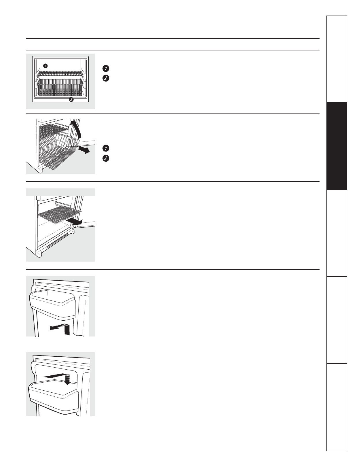
Freezer Shelf and Basket
A full-width fixed wire shelf
A full-width sliding wire basket
Basket Removal
To remove the full-width sliding wire basket
on door models:
Open the basket out to its full extension.
Lift up the front of the basket and pull
straight out to remove.
Fixed Shelf Removal
NOTE: The full-width wire shelf is not intended
to slide.
To remove for cleaning:
Hold the shelf at the front and pull it firmly
forward.
NOTE: Do not fill basket higher than the rim of
the basket. This may cause basket to stick or
jam when opening or closing.
When replacing the full-width sliding
wire basket:
Insert the wire basket into the lower liner’s
rails and push back into place.
When replacing the full-width sliding wire
shelf:
Insert the wire shelf into the upper liner’s rails
and push back into place.
Instructions
Installation
To remove
To replace
Non-Adjustable Shelf on Freezer Door
To remove: Lift the shelf straight up;
then pull out.
To replace: Engage the shelf in the molded
supports on the door and push down. It will
lock in place.
Consumer SupportTroubleshooting TipsOperating InstructionsSafety Instructions
9
Page 10
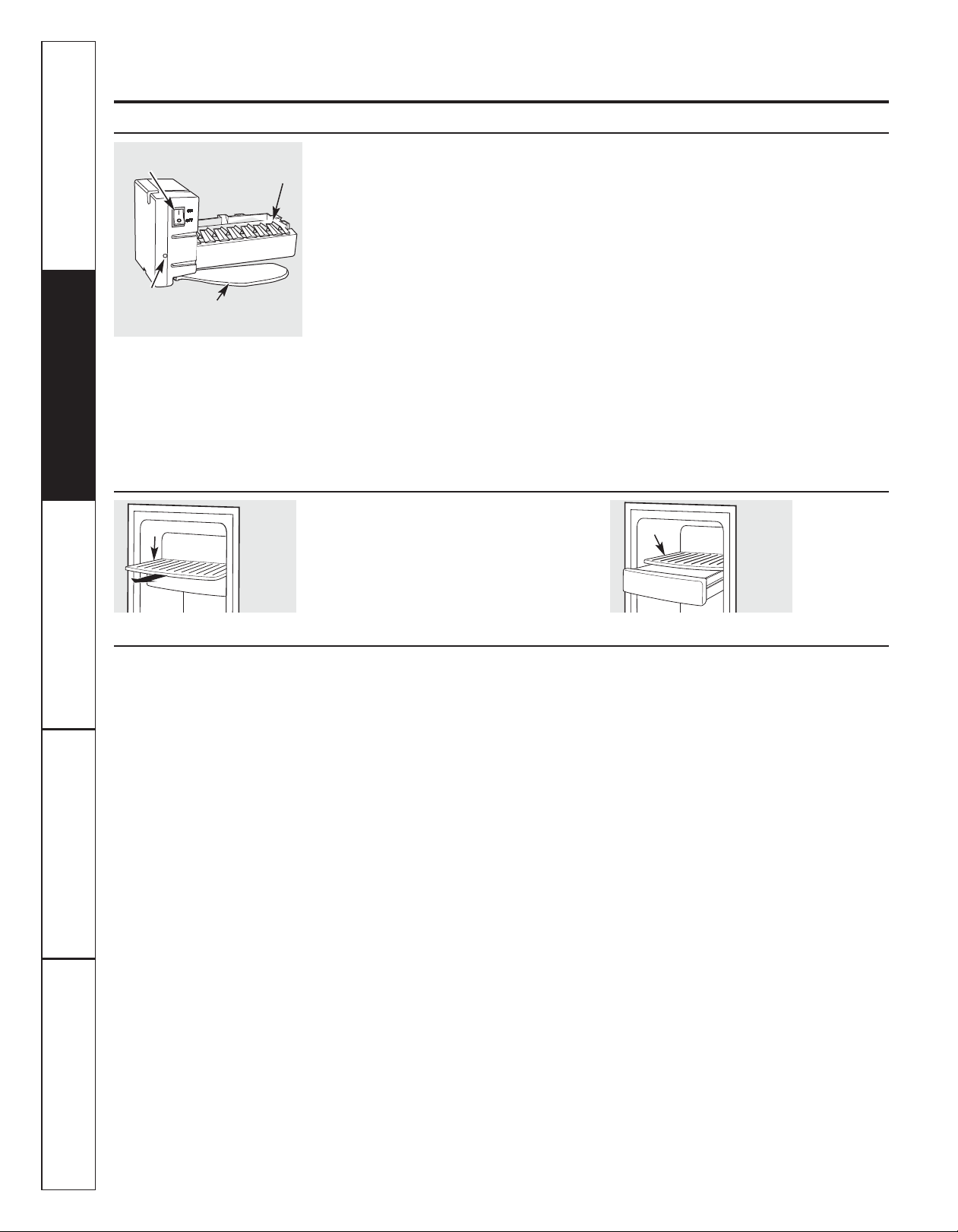
About the automatic icemaker. (on some models)
A newly installed refrigerator may take 12 to 24 hours to begin making ice.
Power
Switch
Green
Power
Light
Shelf
To reach the power switch.
Feeler Arm
Ice Bin
Icemaker
Automatic Icemaker
The icemaker will produce seven cubes per cycle—
approximately 100–130 cubes in a 24-hour period,
depending on freezer compartment temperature,
room temperature, number of door openings and
other use conditions.
See below for how to access ice and reach the
power switch.
If the refrigerator is operated before the water
connection is made to the icemaker, set the power
switch in the O (off) position.
When the refrigerator has been connected to
the water supply, set the power switch to the l (on)
position. The icemaker power light will turn green
when the freezer light switch is pressed in or when
the freezer door is closed.
The icemaker will fill with water when it cools to
15°F (–10°C). A newly installed refrigerator may
take 12 to 24 hours to begin making ice cubes.
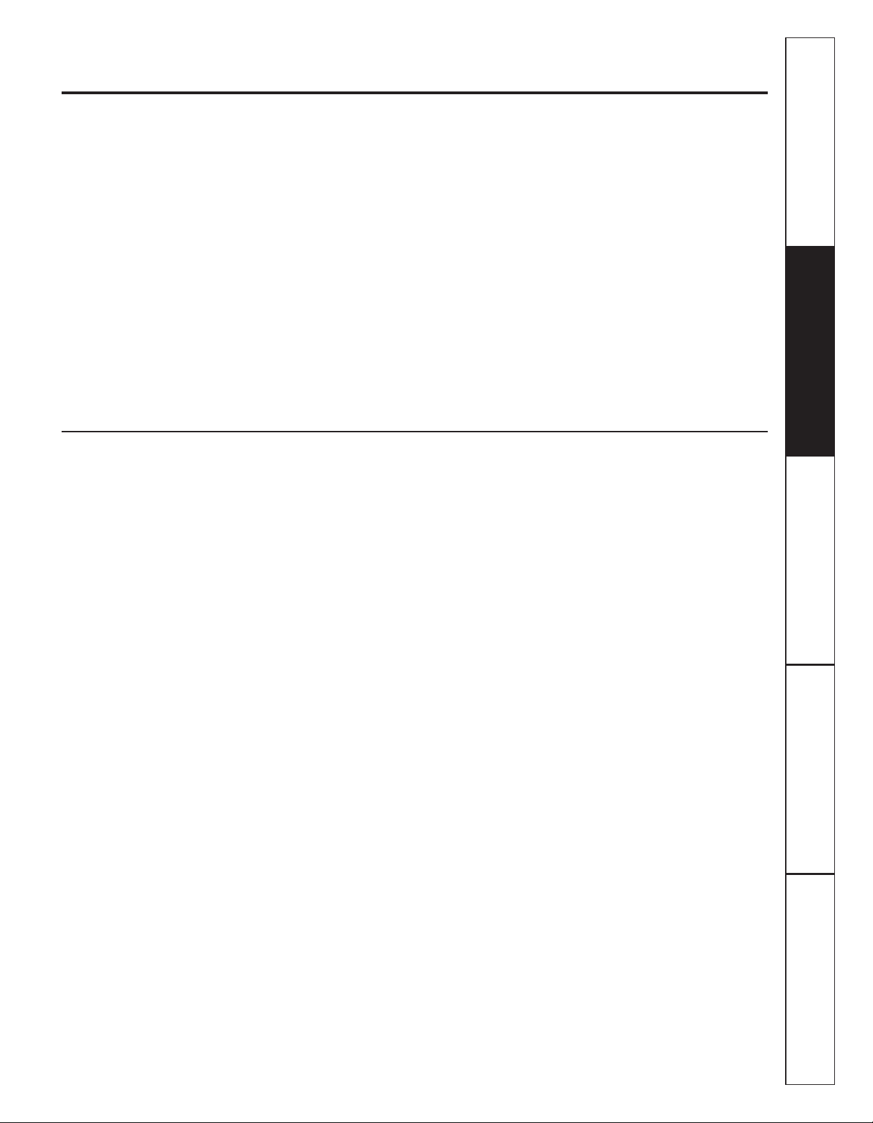
Accessing Ice and Reaching
the Power Switch
To reach the icemaker power switch, pull
the shelf above the ice bin straight out. Always
be sure to replace the shelf.
To access ice, simply pull the bin forward.
You will hear a buzzing sound each time
the icemaker fills with water.
Throw away the first few batches of ice to allow
the water line to clear.
Be sure nothing interferes with the sweep
of the feeler arm.
When the bin fills to the level of the feeler arm,
the icemaker will stop producing ice. It is normal
for several cubes to be joined together.
If ice is not used frequently, old ice cubes will
become cloudy, taste stale and shrink.
NOTE: In homes with lower-than-average water
pressure, you may hear the icemaker cycle multiple
times when making one batch of ice.
NOTE: Set the power switch to the O (off) position
if the water supply is shut off.
Shelf
Ice Bin
To access ice.
Installation
Instructions
Icemaker Accessory Kit
If your refrigerator did not come already equipped
with an automatic icemaker, an icemaker
accessory kit is available at extra cost.
Check the back of the refrigerator for the specific
icemaker kit needed for your model.
Consumer Support Troubleshooting Tips Operating Instructions Safety Instructions
10
Page 11
Care and cleaning of the refrigerator. GEAppliances.com
Cleaning the Outside
The door handles and trim. Clean with a
cloth dampened with soapy water. Dry with
a soft cloth. Do not use wax on the door
handles and trim.
Keep the outside clean. Wipe with
a clean cloth lightly dampened with kitchen
appliance wax or mild liquid dish detergent .
Dry and polish with a clean, soft cloth.
Do not wipe the refrigerator with a soiled
dish cloth or wet towel. These may leave
a residue that can erode the paint. Do not
use scouring pads, powdered cleaners,
bleach or cleaners containing bleach
because these products can scratch and
weaken the paint finish.
Cleaning the Inside
To help prevent odors, leave an open box
of baking soda in the refrigerator and freezer
compartments.
Unplug the refrigerator before cleaning.
If this is not practical, wring excess moisture
out of sponge or cloth when cleaning around
switches, lights or controls.
Use an appliance wax polish on the inside
surface between the doors.
Use warm water and baking soda solution—
about a tablespoon (15 ml) of baking soda to
a quart (1 liter) of water. This both cleans and
neutralizes odors. Rinse and wipe dry.
The stainless steel panels and door
handles. Stainless steel (on some models)
can be cleaned with a commercially
available stainless steel cleaner. A spray-on
stainless steel cleaner works best.
Do not use appliance wax or polish on the
stainless steel.
After cleaning the door gaskets, apply a thin
layer of petroleum jelly to the door gaskets
at the hinge side. This helps keep the gaskets
from sticking and bending out of shape.
Avoid cleaning cold glass shelves with hot
water because the extreme temperature
difference may cause them to break.
Handle glass shelves carefully. Bumping
tempered glass can cause it to shatter.
Do not wash any plastic refrigerator parts
in the dishwasher.
Instructions
Installation
11
Consumer SupportTroubleshooting TipsOperating InstructionsSafety Instructions
Page 12

Care and cleaning of the refrigerator.
Behind the Refrigerator
Be careful when moving the refrigerator
away from the wall. All types of floor
coverings can be damaged, particularly
cushioned coverings and those with
embossed surfaces.
Raise the leveling legs located at the bottom
front of the refrigerator.
Pull the refrigerator straight out and return it
to position by pushing it straight in. Moving
Preparing for Vacation
For long vacations or absences, remove
food and unplug the refrigerator. Clean the
interior with a baking soda solution of one
tablespoon (15 ml) of baking soda to one
quart (1 liter) of water. Leave the doors open.
Set the icemaker power switch to the O (off)
position and shut off the water supply to
the refrigerator.
the refrigerator in a side direction may result
in damage to the floor covering or
refrigerator.
Lower the leveling legs until they touch the
floor.
When pushing the refrigerator back, make
sure you don’t roll over the power cord or
icemaker supply line (on some models).
If the temperature can drop below freezing,
have a qualified servicer drain the water
supply system (on some models) to prevent
serious property damage due to flooding.
Installation
Instructions
Preparing to Move
Secure all loose items such as base grille,
shelves and drawers by taping them securely
in place to prevent damage.
When using a hand truck to move the
refrigerator, do not rest the front or back
of the refrigerator against the hand truck.
This could damage the refrigerator. Handle
only from the sides of the refrigerator.
Be sure the refrigerator stays in an upright
position during moving.
Consumer Support Troubleshooting Tips Operating Instructions Safety Instructions
12
Page 13
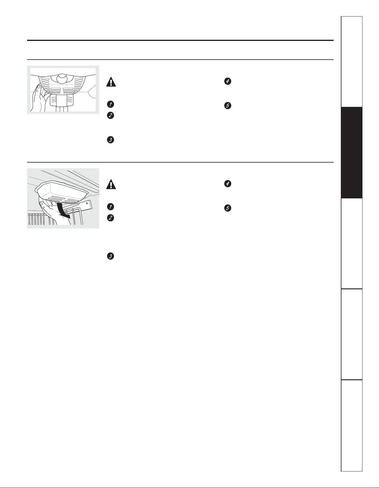
Replacing the light bulbs. GEAppliances.com
Turning the control to the 0ff position does not remove power to the light circuit.
Refrigerator Lights
Appearance may vary
CAUTION: Light bulbs may
be hot.
Unplug the refrigerator.
To remove the light shield, grasp the
shield at the back and pull out to release
the tabs at the back.
Rotate the shield down and then forward
to release the tabs at the front of the
shield.
Freezer Light
CAUTION: Light bulbs may
be hot.
Unplug the refrigerator.
The bulb is located at the top of the
freezer inside a light shield. To remove
the shield, grasp the shield at the back
and pull out to release the tabs at the
back.
After replacing with an appliance bulb
of the same or lower wattage, replace
the shield.
Plug the refrigerator back in.
NOTE: Appliance bulbs may be ordered from
GE Parts and Accessories, 800.626.2002.
After replacing with an appliance bulb
of the same or lower wattage, replace
the shield.
Plug the refrigerator back in.
Instructions
Installation
Rotate the shield down and then forward
to release the tabs at the front of the
shield.
Consumer SupportTroubleshooting TipsOperating InstructionsSafety Instructions
13
Page 14
Installation
Refrigerator
Instructions
Questions? Call 800.GE.CARES (800.432.2737) or Visit our Website at: GEAppliances.com
In Canada, call 1.800.561.3344 or Visit our Website at: www.geappliances.ca
BEFORE YOU BEGIN
Read these instructions completely and carefully.
•
IMPORTANT — Save these instructions
for local inspector’s use.
•
IMPORTANT — Observe all governing
codes and ordinances.
• Note to Installer – Be sure to leave these
instructions with the Consumer.
• Note to Consumer – Keep these instructions for
future reference.
• Skill level – Installation of this appliance requires
basic mechanical skills.
• Completion time – Refrigerator Installation
20 minutes
Water Line Installation
30 minutes
• Proper installation is the responsibility of the
installer.
• Product failure due to improper installation is not
covered under the Warranty.
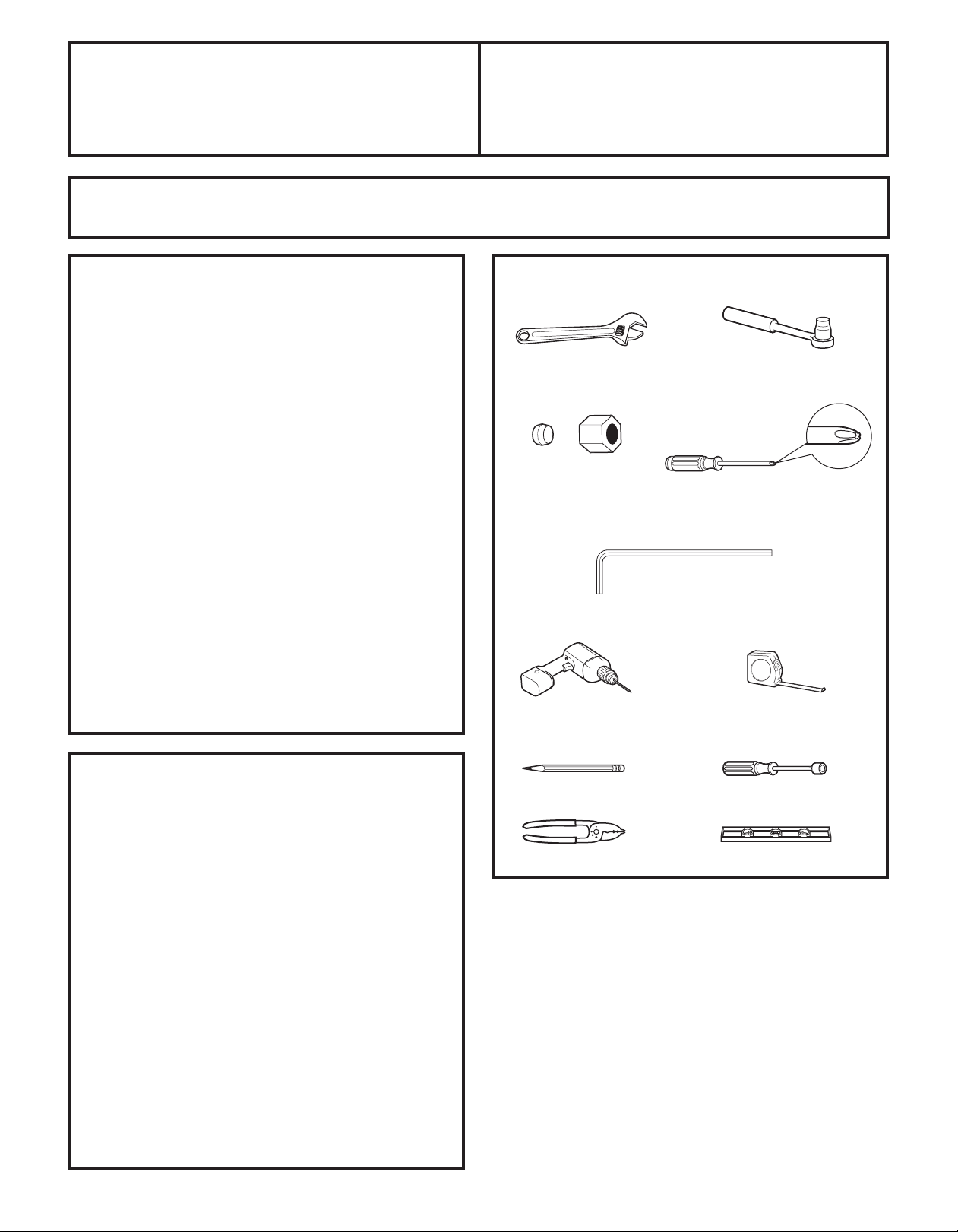
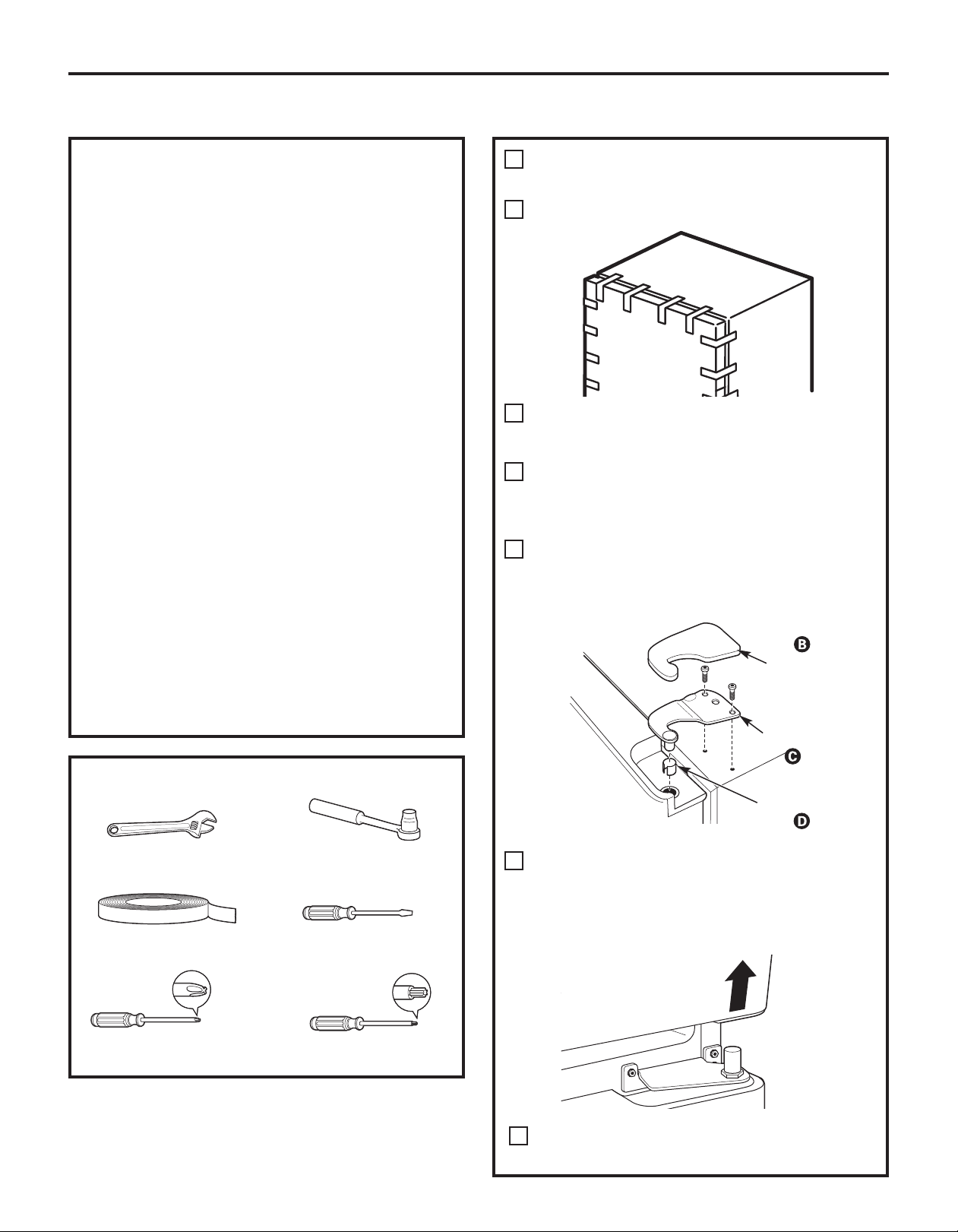
TOOLS YOU MAY NEED
Adjustable Wrench
1/4” Outer Diameter
Compression Nut
and Ferrule (sleeve)
(icemaker models only)
3/32”, 1/8” and 3/16” Allen
1/8” Drill Bit and
Electric or Hand Drill
Models 20 and 22
Phillips Head Screwdriver
wrenches
3/8” and 5/16” Socket
Ratchet/Driver
Tape measure
PREPARATION
MOVING THE REFRIGERATOR INDOORS
If the refrigerator will not fit through a doorway,
the refrigerator door and freezer drawer can be
removed.
• To remove the refrigerator door, see Step 1 in
the Reversing the Door Swing section.
• To remove the freezer drawer, see the Removing
the Freezer Drawer section.
WATER SUPPLY TO THE ICEMAKER AND DISPENSER
(ON SOME MODELS)
If the refrigerator has an icemaker, it will have
to be connected to a cold water line. A GE water supply kit
(containing tubing, shutoff valve, fittings and instructions) is
available at extra cost from your dealer, by visiting our
Website at GEAppliances.com (in Canada at
www.geappliances.ca) or from Parts and Accessories,
800.626.2002 (In Canada 1.888.661.1616).
14
Pencil
Wire Cutters
1/4” Nut Driver
Level
Page 15
Installation Instructions
INSTALLING THE REFRIGERATOR
REFRIGERATOR LOCATION
• Do not install the refrigerator where the temperature
will go below 60°F (16°C) because it will not run often
enough to maintain proper temperatures.
• Do not install the refrigerator where the temperature
will go above 100°F (37°C) because it will not perform
properly.
• Install it on a floor strong enough to support it fully
loaded.
CLEARANCES
Allow the following clearances for ease of installation,
proper air circulation and plumbing and electrical
connections.
Standard Depth
Models
Sides 1/8” (3 mm)
Top 1” (25 mm)
Back 1” (25 mm)
REMOVE TOP CAP (cont.)
(on some models)
REINSTALL DOORS, DRAWERS AND TOP CAP
Carefully lower the door(s) onto the center hinge(s).
E
Reinstall top hinge(s). NOTE: Ensure the door is
properly aligned to the case top to avoid
readjustment of the door during top cap
reinstallation.
Place cap over the top of the refrigerator. Reinstall
F
the original screws in the top and back of the cap.
Reinstall the bottom freezer drawer or door. Refer to
G
“Replacing the Freezer Drawer” section or Step 8 of
“Reversing the Door Swing” section.
A
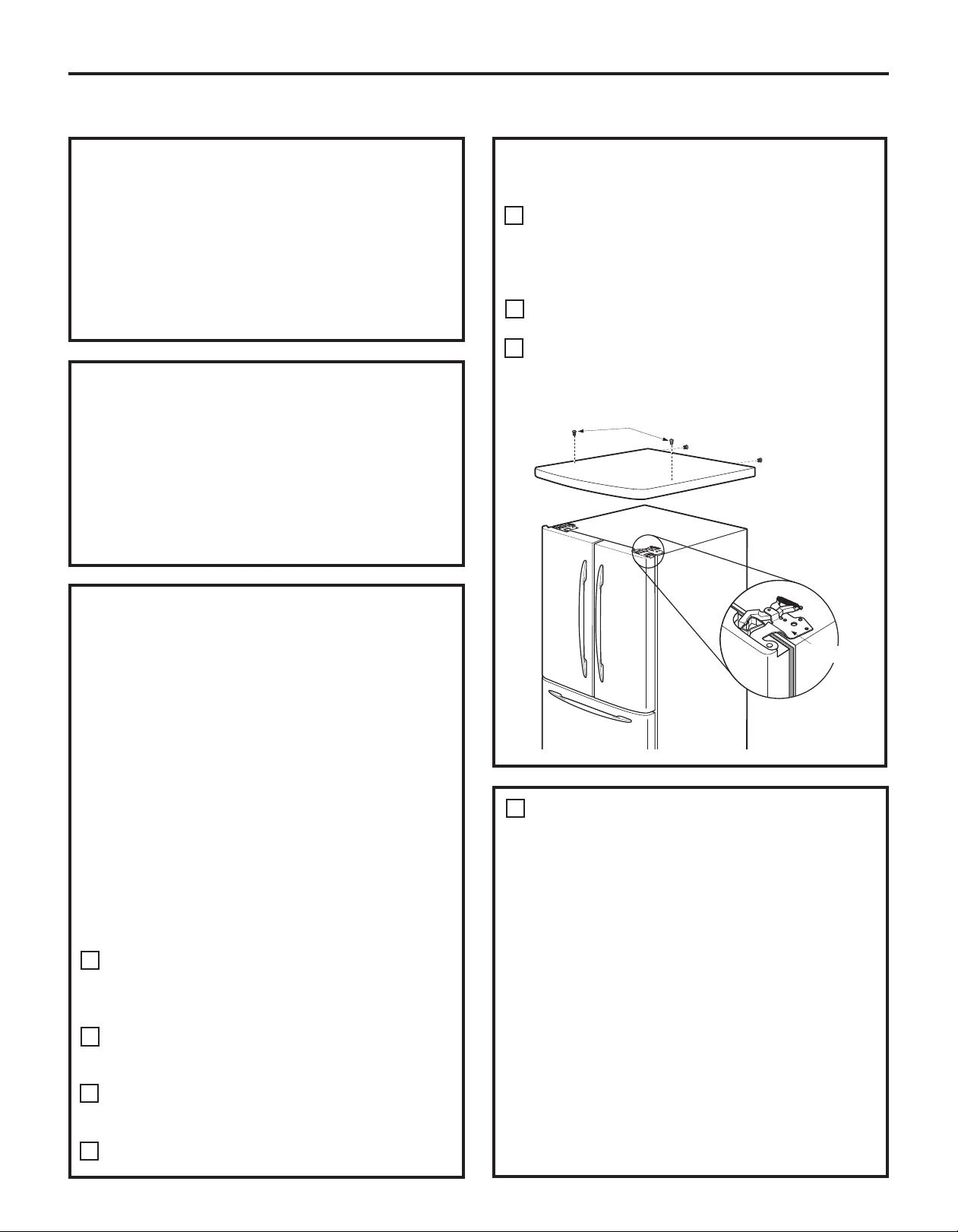
REMOVE TOP CAP (on some models)
•
IMPORTANT NOTE: This refrigerator is 34-1/2” deep.
Doors and passageways leading to the installation
location must be at least 36” wide in order to leave
the doors and handles attached to the refrigerator
while transporting it into the installation location. If
passageways are less than 36”, the refrigerator doors
and handles can easily be scratched and damaged.
The top cap and doors can be removed to allow the
refrigerator to be safely moved indoors. Start with Step A.
• If it is not necessary to remove doors, skip Step A.
Leave tape and all packaging on doors until the
refrigerator is in the final location.
• SKID REMOVAL: Tilt refrigerator to each side to
remove skid.
• NOTE: Use a padded hand truck to move this
refrigerator. Place the refrigerator on the hand truck
with a side against the truck. We strongly recommend
that TWO PEOPLE move and complete this installation.
Locate and remove the two Phillips head screws on
A
the top of the refrigerator. Remove the two screws
on each side at the rear of the top cap. Lift off and
remove top cap.
Remove the fresh-food door(s). Refer to Steps 1 and 3
B
of “Reversing the Door Swing” section or Steps 1 and
2 of “Removing the Doors” section.
Remove the bottom freezer drawer or door. Refer to
C
“Removing Freezer Drawer” section or Step 2 of
“Reversing the Door Swing” section.
Move refrigerator to the installation location.
D
15
1
CONNECTING THE REFRIGERATOR
TO THE HOUSE WATER LINE
(icemaker models)
A cold water supply is required for automatic
icemaker operation. If there is not a cold water
supply, you will need to provide one. See Installing the
Water Line section.
NOTES:
• Before making the connection to the refrigerator,
be sure the refrigerator power cord is not plugged
into the wall outlet.
• If your refrigerator does not have a water filter, we
recommend installing one if your water supply has
sand or particles that could clog the screen of the
refrigerator’s water valve. Install it in the water line
near the refrigerator. If using GE SmartConnect
Refrigerator Tubing Kit , you will need an additional
tube (WX08X10002) to connect the filter. Do not cut
plastic tube to install filter.
Top Hinge B
™
Page 16
Installation Instructions
INSTALLING THE REFRIGERATOR (cont.)
1
CONNECTING THE REFRIGERATOR TO
THE HOUSE WATER LINE
(cont.)
If you are using copper tubing, place a
A
compression nut and ferrule (sleeve) onto the
end of the tubing coming from the house cold
water supply.
If you are using the GE SmartConnect
tubing, the nuts are already assembled to
the tubing.
If you are using copper tubing, insert
B
the end of the tubing into the refrigerator
connection, at the back of the refrigerator,
as far as possible. While holding the tubing,
tighten the fitting.
™
If you are using GE SmartConnect
insert the molded end of the tubing into the
refrigerator connection, at the back of the
refrigerator, and tighten the compression
nut until it is hand tight. Then tighten one
additional turn with a wrench. Overtightening
may cause leaks.
Fasten the tubing into the clamp provided to
C
hold it in position. You may need to pry open
the clamp.
tubing,
2
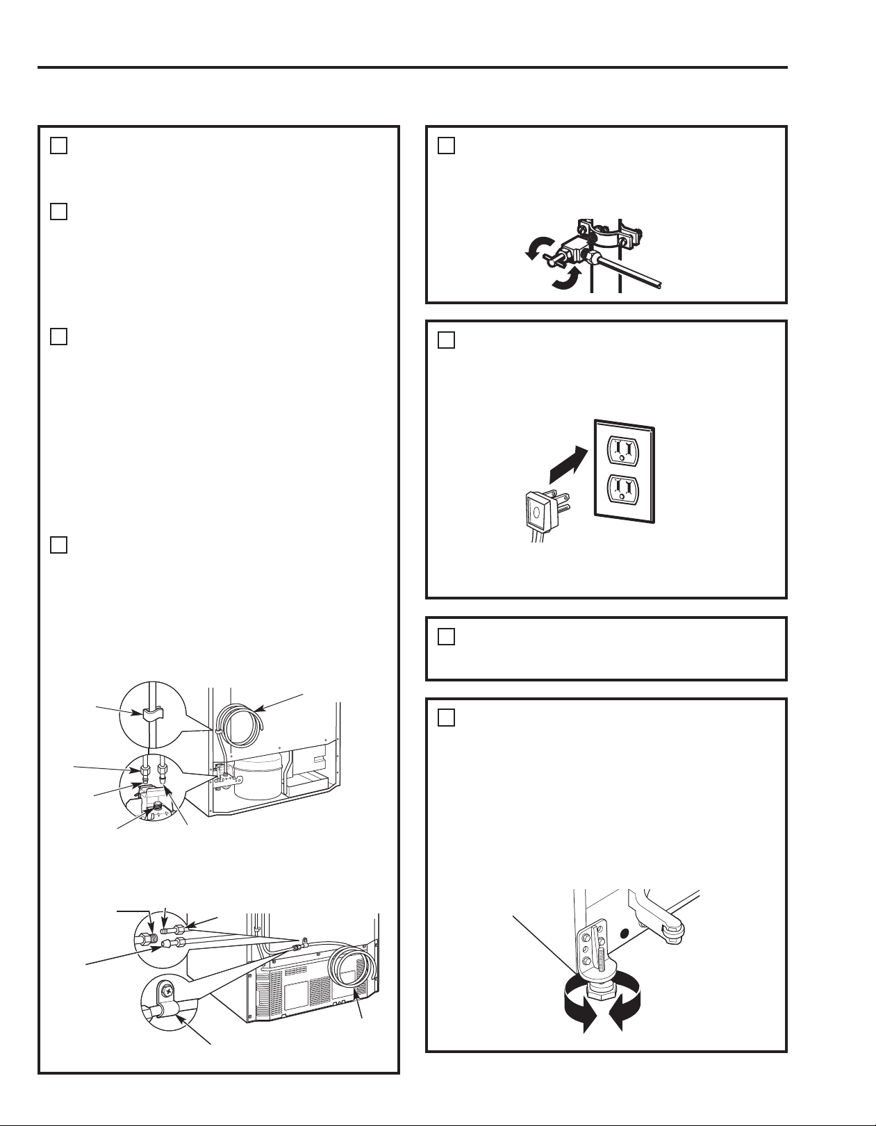
TURN ON THE WATER SUPPLY
(icemaker models)
Turn the water on at the shutoff valve (house
water supply) and check for any leaks.
™
3
PLUG IN THE REFRIGERATOR
On models with an icemaker, before plugging in
the refrigerator, make sure the icemaker power
switch is set to the O (off) position.
See the grounding information attached to the
power cord.
One of the illustrations below will look like
the connection on your refrigerator.
Icemaker-Ready models
Tubing
Clamp
1/4
Compression
Nut
Ferrule
(sleeve)
Refrigerator
Connection
SmartConnect
Tubing
™
1/4 Copper
Tubing
Icemaker-Installed Models
Refrigerator
Connection
SmartConnect
Tubing
Ferrule
(sleeve)
™
1/4
Compression
Nut
4
PUT THE REFRIGERATOR IN PLACE
Move the refrigerator to its final location.
5
LEVEL THE REFRIGERATOR
Adjustable legs at the front corners of the
refrigerator should be set so the refrigerator is
firmly positioned on the floor, and the front is
raised just enough that the door closes easily
when opened about halfway.
To adjust the leveling legs, turn the legs
clockwise to raise the refrigerator,
counterclockwise to lower it.
Tubing Clamp
1/4 Tubing
16
Page 17
Installation Instructions
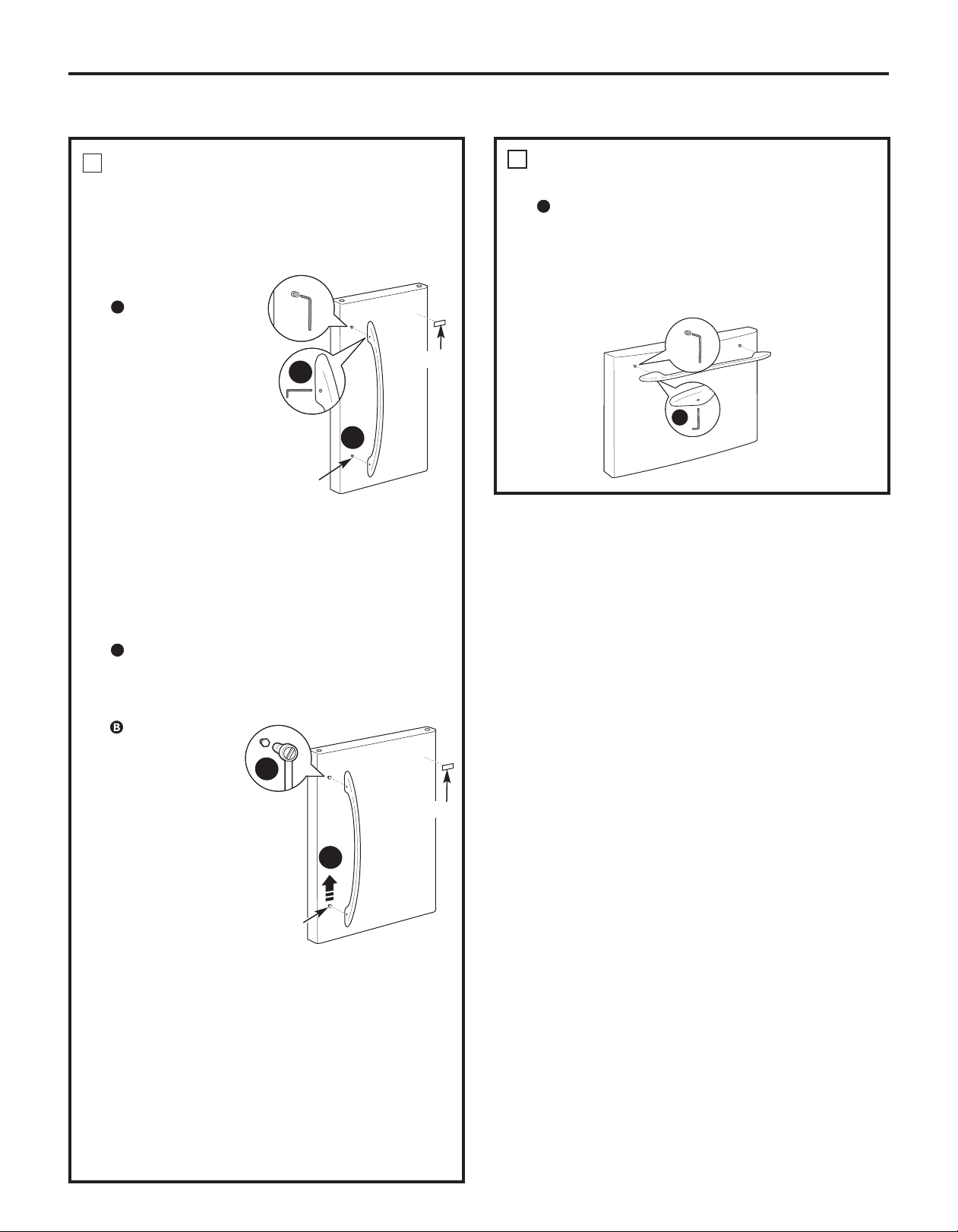
6
REMOVE THE FRESH FOOD
DOOR HANDLE
(For placement in the installation location
or reversal of the handles – on some
models)
Stainless steel (on
some models):
A
REMOVING
THE DOOR
HANDLE: Loosen
the set screws
with the 3/32”
Allen wrench
and remove
the handle.
NOTE: For
Double Door
models follow
the same
procedure on
the opposite door.
A
B
Mounting
Fasteners
(appearance may vary)
Badge
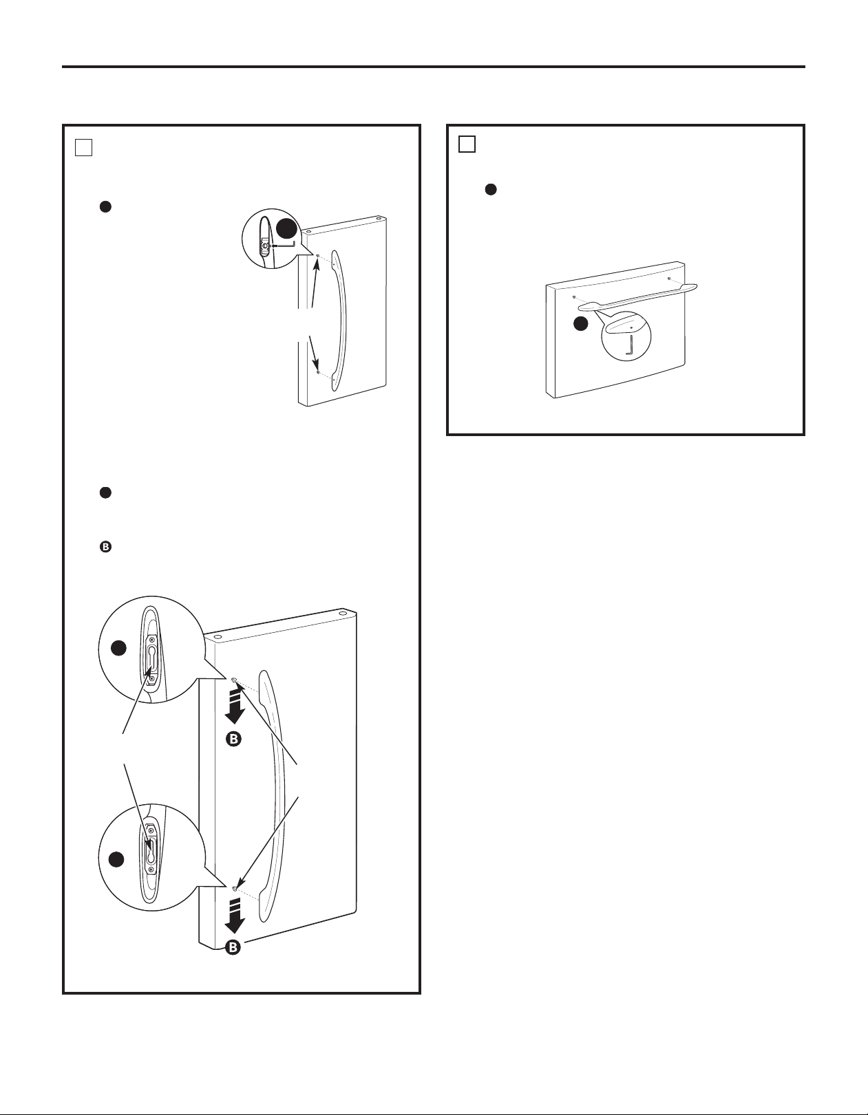
7
REMOVE THE FREEZER DOOR HANDLE
Stainless steel and plastic handles:
A
Loosen the set screws located on the
underside of the handle with the 1/8” Allen
wrench and remove the handle.
NOTE: If the handle mounting fasteners need
to be tightened or removed, use a 3/16” Allen
wrench.
A
Plastic handle
(on some models):
A
REMOVING THE DOOR HANDLE: Depress the
tab on the underside of the handle and slide
the handle up and off of the mounting
fasteners.
REVERSING THE
DOOR HANDLE
(on some
B
models):
• Remove
the handle
mounting
fasteners with
A
a 3/16” Allen
wrench and
transfer
Mounting
Fasteners
the handle
mounting
(appearance may vary)
fasteners to
the right side.
• Remove the logo badge.
• Remove and transfer the plug button to
the left side of the fresh food door. NOTE:
Use a flat plastic edge to prevent
damaging the door. Remove any adhesive
on the door with a mild detergent. Remove
the paper covering on the adhesive
backing on the logo badge prior to carefully
attaching the badge to the door.
Badge
17
Page 18
Installation Instructions
INSTALLING THE REFRIGERATOR (cont.)
9
8
ATTACH THE FRESH FOOD
DOOR HANDLE
Stainless steel handle:
A
Attach the
handle to the
handle mounting
fasteners and
tighten the set
screws with a
3/32” Allen
wrench.
NOTE: For
Double Door
models follow
the same
procedure on the
opposite door.
(appearance may vary)
A
Mounting
Fasteners
ATTACH THE FREEZER DOOR HANDLE
Stainless steel and plastic handles:
A
Attach the handle firmly to the mounting
fasteners and tighten the set screws on
the bottom of the handle with a 1/8” Allen
wrench.
A
(appearance may vary)
Plastic handle:
A
Attach the handle to the handle mounting
fasteners by aligning the slots with the
handle mounting fasteners.
Slide it down until it is firmly locked into
position.
A
Slots on back of
handle
Mounting
fasteners
A
(appearance may vary)
18
Page 19
Installation Instructions
10
LEVEL THE REFRIGERATOR
The leveling legs have 2 purposes:
1) Leveling legs adjust so the refrigerator is
firmly positioned on the floor and does not
wobble.
2) Leveling legs serve as a stabilizing brake
to hold the refrigerator securely in position
during operation and cleaning. The leveling
legs also prevent the refrigerator from
tipping.
Remove the grille by removing the two Phillips
A
head screws.
SET THE CONTROLS
11
Set the controls to the recommended setting.
Turn the leveling legs clockwise to raise
B
the refrigerator, counterclockwise to lower it.
CAUTION: To avoid possible
personal injury or property damage,
the leveling legs must be firmly touching
the floor.
Replace the base grille by inserting the two
C
Phillips head screws.
REMOVE PACKAGING, START
12
ICEMAKER
A) Remove all tape, foam and protective
packing from shelves and drawers.
B) Remove the tie downs from the freezer
baskets.
C) Place half width basket onto drawer slides.
See About the freezer section for instructions.
Set the icemaker power switch to the I (on) position.
The icemaker will not begin to operate until it
reaches its operating temperature of 15°F (–9°C) or
below. It will then begin operation automatically. It
will take 2–3 days to fill the ice bin.
(icemaker models)
Power
switch
19
NOTE: In lower water pressure conditions, the
water valve may turn on up to 3 times to
deliver enough water to the icemaker.
Page 20
Installation Instructions
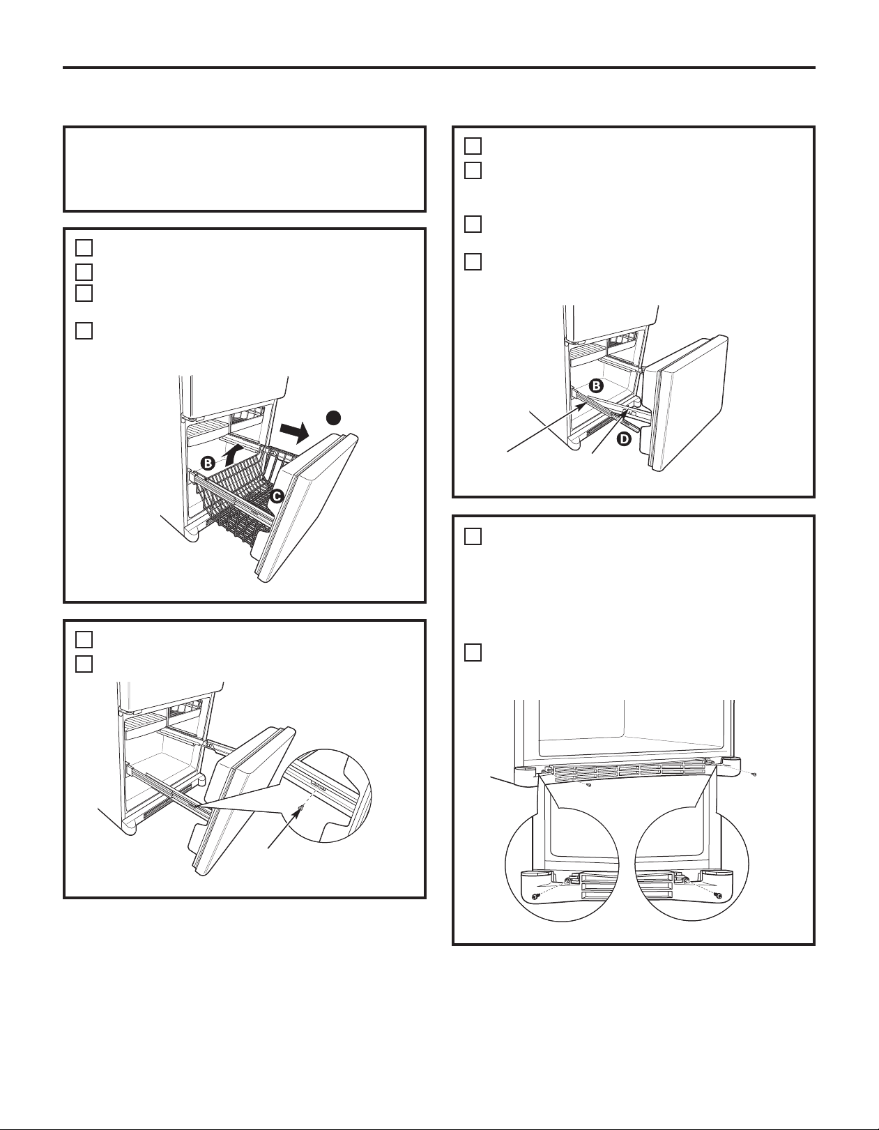
REMOVING THE FREEZER DRAWER (on some models)
The freezer drawer can be removed, if needed,
to fit through tight areas.
Read these instructions completely and carefully.
1
REMOVE THE BASKET
Open the freezer drawer until it stops.
A
The freezer basket rests on a frame inside the
B
freezer drawer. Lift the basket up at the back.
Lift the front up and lift the entire basket up
C
and out of the drawer.
A
2
REMOVE THE DRAWER FRONT
Remove the screw on each side of the railing.
A
2
REMOVE THE DRAWER FRONT (cont.)
Lift up on both sides of the freezer drawer
B
handle to separate the drawer railings from
the rail assemblies.
C
Set the drawer front on a non-scratching
surface.
D
Push the rail assemblies back into locking
position.
Rail Assembly
REMOVE THE BASE GRILLE
3
Drawer
Assembly
(if needed)
If, after removing the freezer drawer and
refrigerator door, the refrigerator will still not
fit through a doorway, the base grille can be
removed.
Remove the base grille by removing the screws.
A
Screw
20
Page 21
Installation Instructions
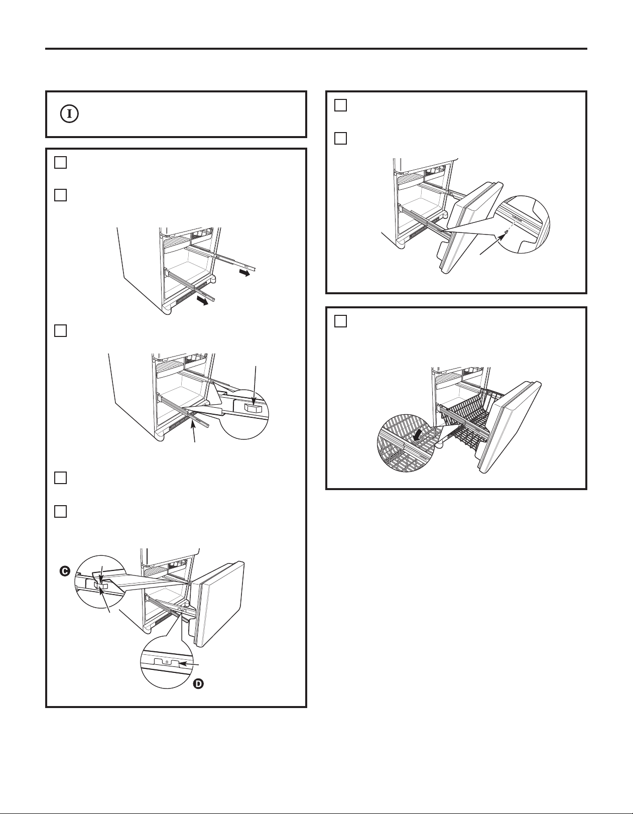
REPLACING THE FREEZER DRAWER (on some models)
Two people may be required to complete
this procedure.
1
ATTACH AND SECURE THE DRAWER
FRONT TO THE SLIDES
Pull out the rail assemblies to the full length
A
on each side of the cabinet.
Locate the slots on the inside of the rail
B
assemblies near the back.
Slot
1
ATTACH AND SECURE THE DRAWER
FRONT TO THE SLIDES
Replace the screws on both rail assemblies.
E
2
REPLACE THE FREEZER BASKET
Replace the lower freezer basket by lowering it
into the frame.
(cont.)
Screw
Rail assembly
C
Insert the hooks at the back of the drawer
railings into the slots on the rail assemblies.
Lower the front of the drawer, making sure the
D
tabs on the sides of the railings fit into the front
slots in the rail assemblies.
Hook
Slot
Tab
21
Page 22
Installation Instructions
REVERSING THE DOOR SWING (Single Door Refrigerator Models only)
1
IMPORTANT NOTES
When reversing the door swing:
NOTE: Door swing is not reversible on stainless
steel models.
• Read the instructions all the way through before
starting.
• Parts are included in the door hinge kit.
• Handle parts carefully to avoid scratching paint.
• Set screws down by their related parts to avoid
using them in the wrong places.
• Provide a non-scratching work surface for
the doors.
IMPORTANT: Once you begin, do not move the
cabinet until door-swing reversal is completed.
These instructions are for changing the hinges
from the right side to the left side—if you ever want
to change the hinges back to the right side, follow
these same instructions and reverse all references
to left and right.
• Once door swing is finalized, ensure the logo
badge is properly aligned and permanently
secured to the door by removing the adhesive
cover on the back side. NOTE: A replacement
logo badge is included in the hinge kit.
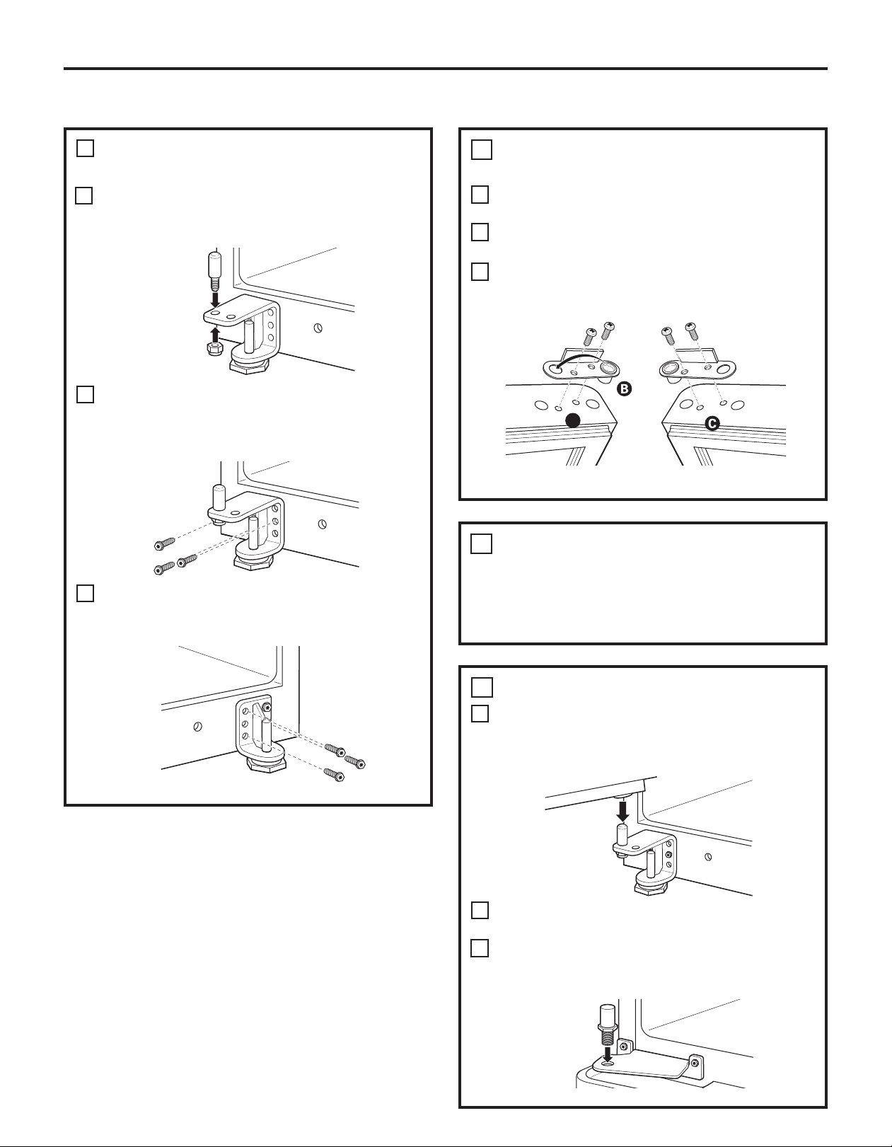
Unplug the refrigerator from its electrical outlet.
Empty all door shelves, including the dairy
compartment.
REMOVE THE
REFRIGERATOR DOOR
Tape the door shut with masking tape.
A
B
Remove the hinge cover on top of the
refrigerator door by carefully prying it up with a
putty knife, if necessary.
C
Using a 5/16” socket ratchet/driver, remove
the bolts securing the top hinge to the cabinet.
Then lift the hinge straight up to free the hinge
pin from the socket in the top of the door.
D
Carefully remove the door thimble from inside
the socket. This will be used again when
reinstalling the door on the other side.
Hinge Cover
Top Hinge
TOOLS YOU WILL NEED
Adjustable Wrench
Masking Tape
Phillips Screwdriver
5/16” Socket
Ratchet/Driver
Thin-blade Screwdriver
Torx T-20 Driver
22
Door Thimble
Remove the tape and tilt the door away from
E
the cabinet. Lift the door off the center hinge
pin. Ensure that the plastic hinge pin thimble
remains on the hinge pin or inside door hinge
pin hole located in the bottom of the door.
Set the door on a non-scratching surface with
F
the inside up.
Page 23

Installation Instructions
2
REMOVE THE FREEZER DOOR
Tape the door shut with masking tape.
A
Remove hinge pin from hinge bracket. This will
B
be used again with the new hinge bracket for
the other side.
Remove the tape and tilt the door away from
C
the cabinet. Lift the door off the bottom
hinge pin.
D
Remove the button plug from the left side of
the door. Remove the door thimble from the
right side of the door. Install the door thimble
into the hole on the left and the button plug
into the hole on the right.
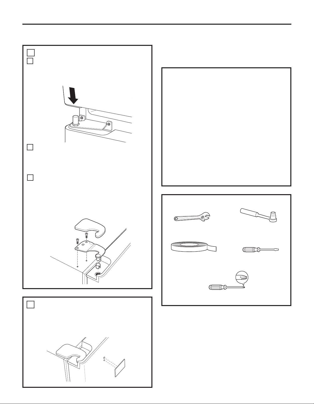
3
TRANSFER CENTER HINGE
BRACKET
B
Transfer the plug button and screw hole
cover in the hinge holes on the left side
to the right side.
Install the new center hinge bracket from the
C
kit on the left side.
(cont.)
E
Set the door on a non-scratching surface, with
the inside up.
3
TRANSFER CENTER HINGE BRACKET
Using a 5/16” socket ratchet/driver, remove the
A
bolts securing the center hinge to the cabinet.
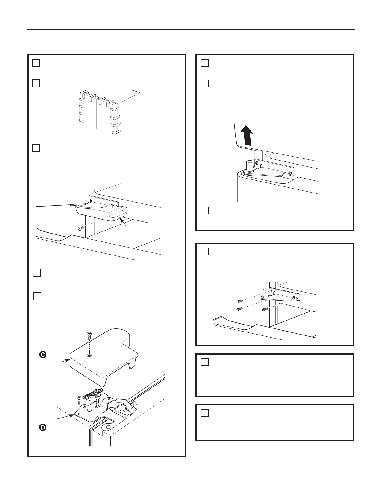
4
REMOVE BOTTOM HINGE AND
LEVELING LEG
Using a 1/2” socket ratchet/driver, remove the
A
nut and hinge pin from the hinge bracket with
leveling leg. Using a 5/16” socket ratchet/driver,
remove the screws from the bottom hinge
bracket. These will be reinstalled on the
other side.
Bottom Hinge
Bracket
Using a 5/16” socket ratchet/driver, remove
B
the screws from the leveling leg bracket on
the other side. These will be reinstalled on the
opposite side.
23
Leveling Leg
Bracket
Page 24
Installation Instructions
REVERSING THE DOOR SWING (cont.)
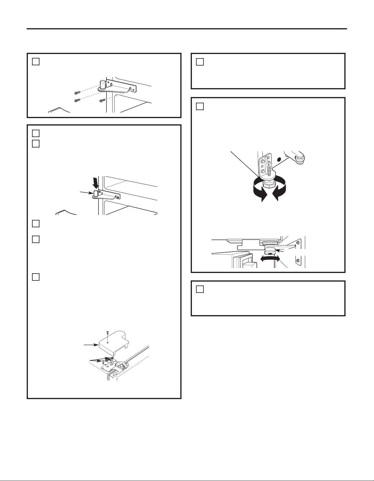
5
INSTALL BOTTOM HINGE AND
LEVELING LEG
Using a 1/2” socket ratchet/driver, install the
A
hinge pin and nut in the opposite hole on the
hinge bracket with leveling leg.
Using a 5/16” socket ratchet/driver, install the
B
hinge bracket with leveling leg on the left side
of the refrigerator. The pin will be toward the
outside of the refrigerator.
Using a 5/16” socket ratchet/driver, install the
C
leveling leg bracket on the right side of the
refrigerator.
6
TRANSFER REFRIGERATOR AND
FREEZER DOOR STOPS
Remove the door stop on the right side of the
A
bottom of the door by removing the two screws.
B
Move the plastic hinge hole thimble to the
opposite hole.
Install the door stop on the left side, making
C
sure to line up the screw holes in the door stop
with the holes in the bottom of the door.
A
Bottom of Door (Right Side) Bottom of Door (Left Side)
7
TRANSFER REFRIGERATOR
DOOR HANDLE TO RIGHT
Refer to Remove the Fresh Food Door Handle
and Attach the Fresh Food Door Handle
sections for instructions.
24
8
REHANG FREEZER DOOR
Lower the freezer door onto the bottom hinge pin.
A
Ensure that the plastic hinge pin thimble is on the
hinge pin or inside the door hinge pin hole located
in the bottom of the door.
Straighten the door and line it up with the
B
center hinge bracket.
Install the center hinge pin with a 3/4” socket
C
ratchet/driver. Turn it until it extends through
the hinge bracket and into the freezer door.
Page 25
Installation Instructions
9
REHANG REFRIGERATOR DOOR
Lower the refrigerator door onto the center hinge
A
pin. Ensure that the plastic hinge pin thimble is on
the center hinge pin or inside door hinge pin hole
located in the bottom of the door.
Insert the door thimble into the hinge hole
B
on top of the refrigerator door and then
insert the top hinge pin. Make sure the door
is aligned with the cabinet. Attach the hinge
to the top of the cabinet loosely with the bolts.
Make sure the gasket on the door is flush against
C
the cabinet and is not folded. Support the door on
the handle side and make sure the door is straight
and the gap between the doors is even across the
front. While holding the door in place, tighten the
top hinge bolts. Replace the hinge cover.
REMOVING THE DOORS
(Double Door Refrigerator Models only)
IMPORTANT NOTES
NOTE: Door swing is not reversible.
• Read the instructions all the way through before
starting.
• Handle parts carefully to avoid scratching paint.
• Set screws down by their related parts to avoid
using them in the wrong places.
• Provide a non-scratching work surface for
the doors.
IMPORTANT: Once you begin, do not move
the cabinet.
These instructions are for removing the doors.
Unplug the refrigerator from its electrical outlet.
Empty all door shelves, including the dairy
compartment.
TOOLS YOU WILL NEED
INSTALL THE LOGO BADGE
10
Remove the adhesive backing paper
and align the pins on the back of the badge
with the holes in the door. Apply pressure to
the badge to ensure it sticks to the door.
Adjustable Wrench
Masking Tape
Phillips Screwdriver
3/8 and 10 mm Socket
Ratchet/Driver
Thin-blade Screwdriver
25
Page 26
Installation Instructions
REMOVING THE DOORS (Double Door Refrigerator Models only)
1
REMOVE THE
REFRIGERATOR DOORS
Tape the doors shut with masking tape.
A
B
Start with left-hand door first: Remove
the screw securing the center hinge cover, lift
the hinge cover and place to the side on top of
the refrigerator.
Remove hinge cover
(1 Phillips screw)
1
REMOVE THE REFRIGERATOR DOORS
(cont.)
Remove the tape and tilt the door away from
E
the cabinet. Lift the door off the center hinge
pin. Ensure that the plastic hinge pin thimble
remains on the hinge pin or inside door hinge
pin hole located in the bottom of the door.
Set the door on a non-scratching surface with
F
the inside up.
Remove the hinge cover on top of the
C
refrigerator door by removing the Phillips head
screw and pulling the cover up.
Using a 5/16” socket ratchet/driver, remove
D
the bolts securing the top hinge to the cabinet.
Then lift the hinge straight up to free the hinge
pin from the socket in the top of the door.
Hinge Cover
Top Hinge
2
REMOVE CENTER HINGE
Using a 5/16” socket ratchet/driver, remove the
bolts securing the center hinge to the cabinet.
Set the hinge and bolts aside.
3
REMOVE OPPOSITE DOOR
Follow the same procedure on the opposite
door. There are no center hinge covers on the
opposite side.
4
REMOVE FREEZER DRAWER
Refer to the Removing the Freezer Drawer
section for instructions.
26
Page 27
Installation Instructions
REPLACING THE DOORS (Double Door Refrigerator Models only)
1
INSTALL CENTER HINGE
Install the center hinge on each side.
2
REHANG REFRIGERATOR DOORS
Lower the refrigerator door onto the center
A
hinge pin. Ensure that the plastic hinge pin
thimble is on the center hinge pin or inside
door hinge pin hole located in the bottom
of the door.
Hinge Pin
Securely tape the door shut with masking tape
B
or have a second person support the door.
C
Insert the top hinge pin into the hinge hole on
top of the refrigerator door. Make sure the door
is aligned with the cabinet and opposite door.
Attach the hinge to the top of the cabinet
loosely with the bolts.
Make sure the gasket on the door is flush
D
against the cabinet and is not folded. Make
sure the door is straight and the gap between
the doors is even across the front. While
holding the aligned door in place, tighten
the top hinge bolts. Replace the hinge cover
and screw.
3
REPLACE OPPOSITE DOOR
Follow the same procedure on the opposite
door. There is no water line or hinge cover.
ALIGN DOUBLE DOORS
4
If the top of the doors are uneven, first try to
raise the lowest door by turning the leveling leg
on the same side as the door until the doors
are even. If the unit rocks, re-adjust the leveling
legs to the extent that the unit is stable.
If the doors remain uneven, turn the adjustable
pin to raise, or lower, the left door to match
the right door. Use a 1/4” Allen wrench to turn
the pin.
Adjustable pin
5
REPLACE FREEZER DRAWER
Refer to the Replacing the Freezer Drawer
section for instructions.
Hinge Cover
Top Hinge Bolts
(appearance may vary)
27
Page 28
Installation Instructions
INSTALLING THE WATER LINE (ICEMAKER MODELS)
BEFORE YOU BEGIN
Recommended copper water supply kits are
WX8X2, WX8X3 or WX8X4, depending on the
amount of tubing you need. Approved plastic
water supply lines are GE SmartConnect
Refrigerator Tubing (WX08X10006, WX08X10015
and WX08X10025).
When connecting your refrigerator to a GE Reverse
Osmosis Water System, the only approved
installation is with a GE RVKit. For other reverse
osmosis water systems, follow the manufacturer’s
recommendations.
If the water supply to the refrigerator is from
a Reverse Osmosis Water Filtration System
AND the refrigerator also has a water filter,
use the refrigerator’s filter bypass plug. Using
the refrigerator’s water filtration cartridge in
conjunction with the RO filter can result in hollow
ice cubes.
This water line installation is not warranted by
the refrigerator or icemaker manufacturer. Follow
these instructions carefully to minimize the risk of
expensive water damage.
Water hammer (water banging in the pipes) in
house plumbing can cause damage to refrigerator
parts and lead to water leakage or flooding. Call a
qualified plumber to correct water hammer before
installing the water supply line to the refrigerator.
To prevent burns and product damage, do not hook
up the water line to the hot water line.
If you use your refrigerator before connecting
the water line, make sure the icemaker power
switch is in the O (off) position.
Do not install the icemaker tubing in areas where
temperatures fall below freezing.
When using any electrical device (such as a power
drill) during installation, be sure the device is double
insulated or grounded in a manner to prevent the
hazard of electric shock, or is battery powered.
All installations must be in accordance with local
plumbing code requirements.
™
WHAT YOU WILL NEED
• Copper or GE SmartConnect™Refrigerator
Tubing kit, 1/4” outer diameter to connect the
refrigerator to the water supply. If using copper, be
sure both ends of the tubing are cut square.
To determine how much tubing you need: measure
the distance from the water valve on the back
of the refrigerator to the water supply pipe.
Be sure there is sufficient extra tubing to allow
the refrigerator to move out from the wall after
installation.
™
GE SmartConnect
are available in the following lengths:
6’ (1.8 m) – WX08X10006
15’ (4.6 m) – WX08X10015
25’ (7.6 m) – WX08X10025
Refrigerator Tubing Kits
28
Page 29
Installation Instructions
WHAT YOU WILL NEED (CONT.)
NOTE: The only GE approved plastic tubing
is that supplied in GE SmartConnect
Refrigerator Tubing kits. Do not use any other
plastic water supply line because the line is
under pressure at all times. Certain types of
plastic will crack or rupture with age and cause
water damage to your home.
• A GE water supply kit (containing tubing,
shutoff valve and fittings listed below) is available
at extra cost from your dealer or from Parts and
Accessories, 800.626.2002 (in Canada
1.888.261.3055).
• A cold water supply. The water pressure must
be between 20 and 120 p.s.i. (1.4–8.1 bar).
™
Install the shutoff valve on the nearest frequently
used drinking water line.
1
SHUT OFF THE MAIN WATER SUPPLY
Turn on the nearest faucet long enough
to clear the line of water.
2
CHOOSE THE VALVE LOCATION
Choose a location for the valve that is easily
accessible. It is best to connect into the side
of a vertical water pipe. When it is necessary
to connect into a horizontal water pipe, make
the connection to the top or side, rather than at
the bottom, to avoid drawing off any sediment
from the water pipe.
• Power drill.
• 1/2” or adjustable wrench.
• Straight and Phillips blade screwdriver.
• Two 1/4 outer diameter compression nuts
and 2 ferrules (sleeves)—to connect the copper
tubing to the shutoff valve and the refrigerator
water valve.
OR
• If you are using a GE SmartConnect
Refrigerator Tubing kit, the necessary fittings
are preassembled to the tubing.
• If your existing copper water line has a flared
fitting at the end, you will need an adapter
(available at plumbing supply stores) to connect
the water line to the refrigerator OR you can cut
off the flared fitting with a tube cutter and then
use a compression fitting. Do not cut formed end
from GE SmartConnect
™
Refrigerator tubing.
™
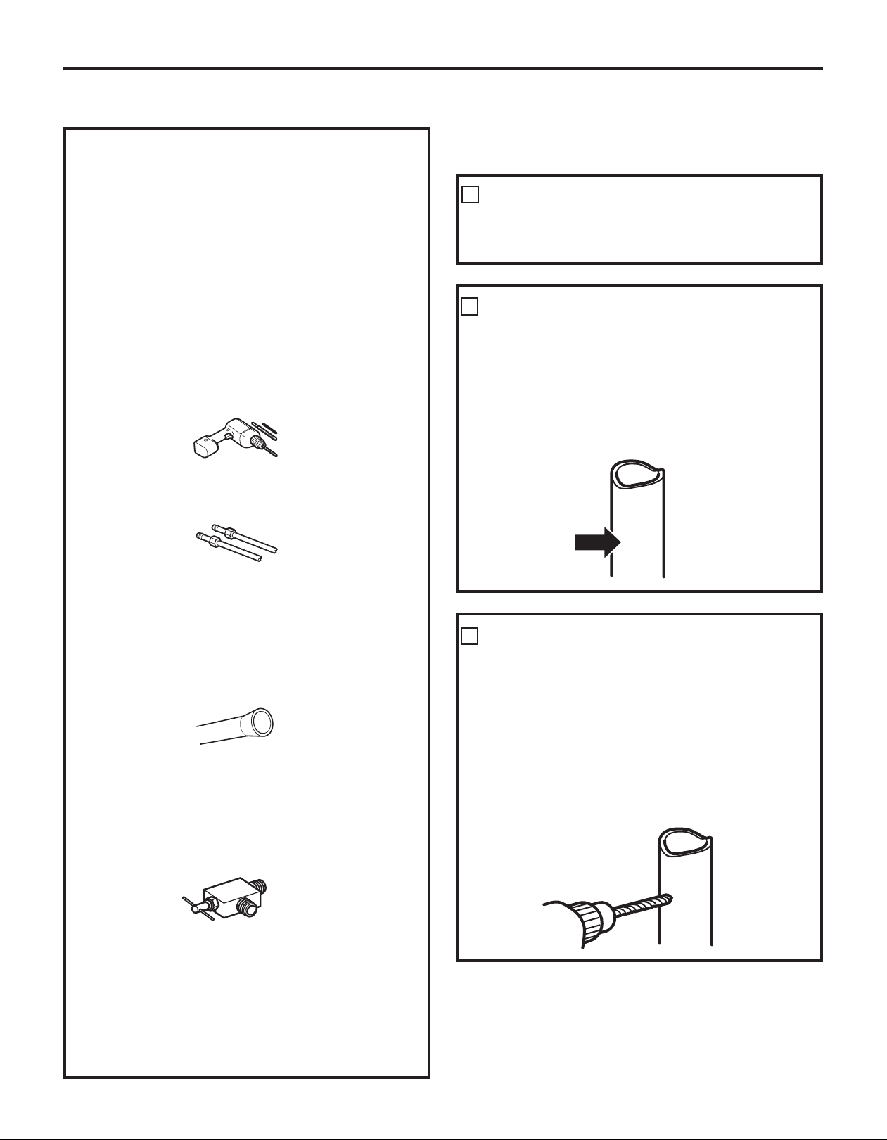
DRILL THE HOLE FOR THE VALVE
3
Drill a 1/4” hole in the water pipe (even if using
a self-piercing valve), using a sharp bit. Remove
any burrs resulting from drilling the hole in
the pipe.
Take care not to allow water to drain into the
drill.
Failure to drill a 1/4” hole may result in reduced
ice production or smaller cubes.
• Shutoff valve to connect to the cold water line.
The shutoff valve should have a water inlet with
a minimum inside diameter of 5/32 at the point
of connection to the COLD WATER LINE. Saddle-
type shutoff valves are included in many water
supply kits. Before purchasing, make sure a
saddle-type valve complies with your local
plumbing codes.
29
Page 30
Installation Instructions
INSTALLING THE WATER LINE (CONT.)
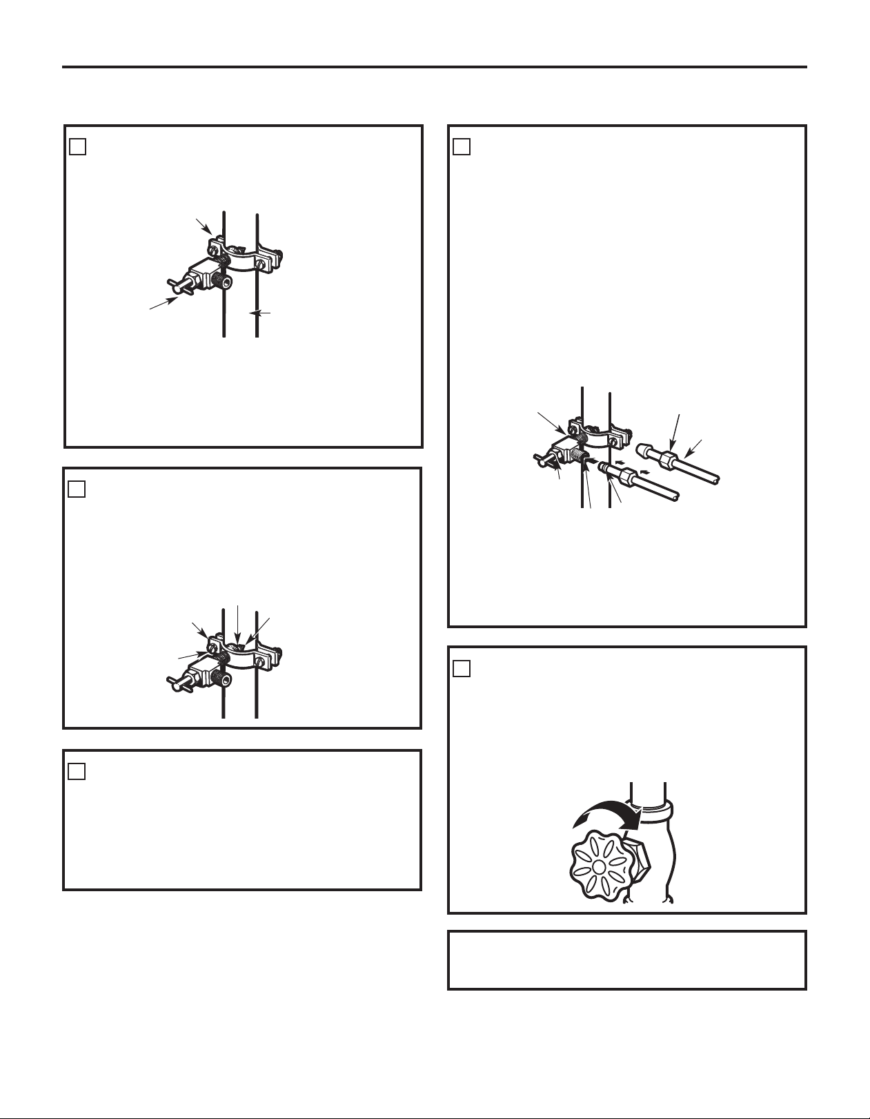
4
FASTEN THE SHUTOFF VALVE
Fasten the shutoff valve to the cold water pipe
with the pipe clamp.
Pipe Clamp
Saddle-Type
Shutoff Valve
Vertical Cold Water Pipe
NOTE: Commonwealth of Massachusetts
Plumbing Codes 248CMR shall be adhered to.
Saddle valves are illegal and use is not permitted
in Massachusetts. Consult with your licensed
plumber.
5
TIGHTEN THE PIPE CLAMP
Tighten the clamp screws until the sealing
washer begins to swell.
NOTE: Do not overtighten or you may crush
the tubing.
Washer
Pipe Clamp
Clamp
Screw
6
ROUTE THE TUBING
Inlet End
Route the tubing between the cold water line
and the refrigerator.
Route the tubing through a hole drilled in the
wall or floor (behind the refrigerator or adjacent
base cabinet) as close to the wall as possible.
7
CONNECT THE TUBING TO THE VALVE
Place the compression nut and ferrule (sleeve)
for copper tubing onto the end of the tubing and
connect it to the shutoff valve.
Make sure the tubing is fully inserted into
the valve. Tighten the compression nut securely.
For plastic tubing from a GE SmartConnect
Refrigerator Tubing kit, insert the molded end
of the tubing into the shutoff valve and tighten
compression nut until it is hand tight, then
tighten one additional turn with a wrench.
Overtightening may cause leaks.
Saddle-Type
Shutoff Valve
Packing Nut
Outlet Valve
Ferrule (sleeve)
Compression Nut
SmartConnect
Tubing
NOTE: Commonwealth of Massachusetts
Plumbing Codes 248CMR shall be adhered to.
Saddle valves are illegal and use is not permitted
in Massachusetts. Consult with your licensed
plumber.
8
FLUSH OUT THE TUBING
Turn the main water supply on and flush out
the tubing until the water is clear.
Shut the water off at the water valve after
about one quart (1 liter) of water has been
flushed through the tubing.
™
™
To complete the installation of the refrigerator,
go back to Step 1 in Installing the Refrigerator.
30
Page 31

Normal operating sounds. GEAppliances.com
Newer refrigerators sound different from older refrigerators.
Modern refrigerators have more features and use newer technology.
Do you hear what I hear? These sounds are normal.
HUMMM...
WHOOSH...
The new high efficiency compressor may run faster
and longer than your old refrigerator and you may
hear a high-pitched hum or pulsating sound while
it is operating.
You may hear a whooshing sound when the
doors close. This is due to pressure equalizing within
the refrigerator.
You may hear the fans spinning at high speeds.
This happens when the refrigerator is first plugged in,
when the doors are opened frequently or when a large
amount of food is added to the refrigerator or freezer
compartments. The fans are helping to maintain the
correct temperatures.
The fans change speeds in order to provide optimal
cooling and energy savings.
CLICKS, POPS,
CRACKS and SNAPS
You may hear cracking or popping sounds when
the refrigerator is first plugged in. This happens as
the refrigerator cools to the correct temperature.
The freezer control will click when starting or stopping
the compressor.
Defrost timer snapping in and out of the defrost cycle.
Expansion and contraction of cooling coils during and
after defrost can cause a cracking or popping sound.
On models with an icemaker, after an icemaking cycle,
you may hear the ice cubes dropping into the ice
bucket.
On models with a dispenser, during water dispense,
you may hear the water lines move at initial dispense
and after dispenser button is released.
Before you call for service…
Troubleshooting Tips
Save time and money! Review the charts on
the following pages first and you may not need to call
for service.
WATER SOUNDS
The flow of refrigerant through the freezer cooling coils
may make a gurgling noise like boiling water.
Water dropping on the defrost heater can cause a
sizzling, popping or buzzing sound during the defrost
cycle.
A water dripping noise may occur during the defrost
cycle as ice melts from the evaporator and flows into
the drain pan.
Closing the door may cause a gurgling sound due to
pressure equalization.
For additional information on normal
icemaker operating sounds, see the
About the automatic icemaker section.
Instructions
Installation
Problem Possible Causes What To Do
Refrigerator does not Refrigerator in defrost cycle. • Wait about 30 minutes for defrost cycle to end.
operate
Vibration or rattling Leveling legs need adjusting. • See Level the Refrigerator.
(slight vibration
is normal)
Control in 0ff position. • Move the control to a temperature setting.
Refrigerator is unplugged. • Push the plug completely into the outlet.
The fuse is blown/circuit • Replace fuse or reset the breaker.
breaker is tripped.
Consumer SupportTroubleshooting TipsOperating InstructionsSafety Instructions
31
Page 32

Before you call for service…
Problem Possible Causes What To Do
Motor operates for Normal when refrigerator • Wait 24 hours for the refrigerator to completely
long periods or cycles is first plugged in. cool down.
on and off frequently.
(Modern refrigerators
with more storage
space and a larger
freezer require more
operating time. They
start and stop often
to maintain even
temperatures.)
Refrigerator or freezer Temperature controls not set • See About the controls.
compartment too warm cold enough.
Frost or ice crystals Door left open. • Check to see if package is holding door open.
on frozen food
(frost within package
is normal)
Installation
Frequent “buzzing” Icemaker power switch is in • Set the power switch to the 0 (off) position. Keeping it
Instructions
sound the I (on) position, but the in the I (on) position will damage the water valve.
Small or hollow cubes Water filter clogged. • Replace filter cartridge with new cartridge or with plug.
Troubleshooting Tips
Often occurs when large • This is normal.
amounts of food are
placed in refrigerator.
Door left open. • Check to see if package is holding door open.
Hot weather or frequent • This is normal.
door openings.
Temperature control • See About the controls.
set at the coldest setting.
Warm weather or frequent • Set the temperature control one step colder.
door openings. See About the controls.
Door left open. • Check to see if package is holding door open.
Door openings too frequent • This is normal.
or too long.
water supply to the refrigerator
has not been connected.
Automatic icemaker Icemaker power switch is • Set the power switch to the I (on) position.
(on some models) not on. The icemaker power light will turn green when the
does not work freezer light switch is pressed in or when the freezer
door is closed.
Water supply turned off or • See Installing the water line.
not connected.
Freezer compartment • Wait 24 hours for the refrigerator to completely
too warm. cool down.
Piled up cubes in the storage • Level cubes by hand.
bin cause the icemaker
to shut off.
Ice cubes stuck in icemaker. • Turn off the icemaker, remove cubes and turn
(Green power light on the icemaker back on.
icemaker blinking.)
Icemaker light is not lit. • This is normal when the freezer door is open. The
icemaker power light will turn green when the freezer
light switch is pressed in or when the freezer door is
closed.
Consumer Support Troubleshooting Tips Operating Instructions Safety Instructions
32
Page 33

GEAppliances.com
Problem Possible Causes What To Do
Ice cubes have Food transmitting odor/taste • Wrap foods well.
odor/taste to ice cubes.
Interior of refrigerator • See Care and cleaning.
needs cleaning.
Slow ice cube freezing Door left open. • Check to see if package is holding door open.
Freezer control not set • See About the controls.
cold enough.
Refrigerator has odor Foods transmitting • Foods with strong odors should be tightly wrapped.
odor to refrigerator.
Interior needs cleaning. • See Care and cleaning.
• Keep an open box of baking soda in the refrigerator;
replace every three months.
• Keep an open box of baking soda in the refrigerator;
replace every three months.
Moisture forms on Not unusual during • Wipe surface dry and reset the refrigerator control
outside of refrigerator periods of high humidity. one setting colder.
Moisture collects inside Too frequent or too • This is normal.
(in humid weather, air long door openings.
carries moisture into
refrigerator when
doors are opened)
Refrigerator or freezer No power at outlet. • Replace fuse or reset the breaker.
compartment light
does not work
Door/drawer does not Leveling legs need adjusting. • See Installing the Refrigerator.
close by itself
Freezer door/drawer This is normal if, after popping • This indicates that there is a good seal on the freezer
pops open when open, the freezer door/drawer door/drawer. If the freezer door/drawer does not
refrigerator door closed on its own. automatically close after popping open, then see the
is closed Problem: Door/drawer does not close by itself, above.
Hot air from bottom Normal air flow cooling
of refrigerator motor. In the refrigeration
Light bulb burned out or loose. • See Replacing the light bulbs.
process, it is normal that
heat be expelled in the
area under the refrigerator.
Some floor coverings will
discolor at these normal
and safe temperatures.
Instructions
Installation
Consumer SupportTroubleshooting TipsOperating InstructionsSafety Instructions
Food freezing in Food too close to the air vent • Move the food away from the air vent.
the refrigerator at the back of the refrigerator.
Refrigerator control is set • Move the refrigerator control to a warmer
too cold. temperature setting one increment at a time.
Orange glow Defrost heater is on. • This is normal.
in the freezer
33
Page 34

Before you call for service…
Troubleshooting Tips
Problem Possible Causes What To Do
No ice cube Supply line or shutoff valve • Call a plumber.
production is clogged.
(on some models)
Handle is loose / Handle needs adjusting. • See Attach the Fresh Food Door Handle and Attach the
handle has a gap Freezer Door Handle sections for detailed instructions.
Refrigerator beeping This is the door alarm. • Close door.
Control setting is On some models, the light bulbs • If the control settings do not light up, check to see if
not lit at the top of the refrigerator the light bulbs are burned out, and replace if necessary.
Water filter clogged. • Replace filter cartridge or remove filter and install plug.
Filter cartridge not • Remove and reinstall filter cartridge, being certain that
properly installed. it locks into place. The blade on the end of the cartridge
should be positioned vertically.
compartment light up the
temperature control settings.
Refrigerator doors are Doors need realigning. • See Align Double Doors section located under
not even (on Double Replacing the Door (Double Door Refrigerator Models
Door models only) only).
Baskets stick or jam Baskets are too full. • To open: remove some of the products from
Installation
when opening or the basket when opened as far as possible.
Instructions
closing Readjust the products left in the basket and
try to open the basket again.
• To close: readjust products in the basket or remove
any product that is above the rim of the basket and
close the basket.
Consumer Support Troubleshooting Tips Operating Instructions Safety Instructions
34
Page 35

Notes. GEAppliances.com
Instructions
Installation
Consumer SupportTroubleshooting TipsOperating InstructionsSafety Instructions
35
Page 36

Notes.
Installation
Instructions
Consumer Support Troubleshooting Tips Operating Instructions Safety Instructions
36
Page 37

Notes. GEAppliances.com
Instructions
Installation
Consumer SupportTroubleshooting TipsOperating InstructionsSafety Instructions
37
Page 38

Notes.
Installation
Instructions
Consumer Support Troubleshooting Tips Operating Instructions Safety Instructions
38
Page 39

Refrigerator Warranty. (For customers in the United States)
All warranty service provided by our Factory Service Centers,
®
or an authorized Customer Care
technician. To schedule service,
on-line, visit us at GEAppliances.com, or call 800.GE.CARES
(800.432.2737). Please have serial number and model number
Staple your receipt here.
Proof of the original purchase
date is needed to obtain service
under the warranty.
available when calling for service.
For The Period Of: GE Will Replace:
GE and GE PROFILE MODELS:
One Year Any part of the refrigerator which fails due to a defect in materials or workmanship.
From the date of the During this limited one-year warranty, GE will also provide, free of charge, all labor and
original purchase related service to replace the defective part.
Thirty Days Any part of the water filter cartridge which fails due to a defect in materials or workmanship.
(Water filter, if included) During this limited thirty-day warranty, GE will also provide, free of charge, a replacement water
From the original filter cartridge.
purchase date of
the refrigerator
GE PROFILE MODELS ONLY:
Five Years Any part of the sealed refrigerating system (the compressor, condenser, evaporator
(GE Profile models only) and all connecting tubing) which fails due to a defect in materials or workmanship.
From the date of the During this limited five-year sealed refrigerating system warranty, GE will also provide,
original purchase free of charge, all labor and related service to replace the defective part in the sealed
refrigerating system.
Instructions
Installation
What GE Will Not Cover:
Service trips to your home to teach you how to use
the product.
Improper installation, delivery or maintenance.
Failure of the product if it is abused, misused, or used for
other than the intended purpose or used commercially.
Loss of food due to spoilage.
Replacement of house fuses or resetting of circuit
breakers.
Damage caused after delivery.
EXCLUSION OF IMPLIED WARRANTIES—Your sole and exclusive remedy is product repair as provided
in this Limited Warranty. Any implied warranties, including the implied warranties of merchantability
or fitness for a particular purpose, are limited to one year or the shortest period allowed by law.
This warranty is extended to the original purchaser and any succeeding owner for products purchased
for home use within the USA. If the product is located in an area where service by a GE Authorized Servicer
is not available, you may be responsible for a trip charge or you may be required to bring the product to an
Authorized GE Service location for service. In Alaska, the warranty excludes the cost of shipping or service calls
to your home.
Replacement of the water filter cartridge, if included, due
to water pressure that is outside the specified operating
range or due to excessive sediment in the water supply.
Replacement of the light bulbs, if included, or water filter
cartridge, if included, other than as noted above.
Damage to the product caused by accident , fire, floods
or acts of God.
Incidental or consequential damage caused by possible
defects with this appliance.
Product not accessible to provide required service.
Consumer SupportTroubleshooting TipsOperating InstructionsSafety Instructions
Some states do not allow the exclusion or limitation of incidental or consequential damages. This warranty
gives you specific legal rights, and you may also have other rights which vary from state to state. To know
what your legal rights are, consult your local or state consumer affairs office or your state’s Attorney General.
Warrantor: General Electric Company. Louisville, KY 40225
39
Page 40

CUSTOMER WARRANTY
(for customers in Canada)
Your refrigerator is warranted to be free of defects in material and workmanship.
What is covered How Long Warranted Parts Labour
(From Date of Sale) Repair or Replace
at Mabe’s Option
Compressor GE Profile: Ten (10) Years GE Profile: Ten (10) Years GE Profile: Five (5) Years
GE and All Other GE and All Other GE and All Other
Brands: One (1) Year Brands: One (1) Year Brands: One (1) Year
Sealed System (including GE Profile: Five (5) Years GE Profile: Five (5) Years GE Profile: Five (5) Years
evaporator, condenser GE and All Other GE and All Other GE and All Other
tubing and refrigerant) Brands: One (1) Year Brands: One (1) Year Brands: One (1) Year
All Other Parts One (1) Year One (1) Year One (1) Year
TERMS AND CONDITIONS:
This warranty applies only for single family domestic
use in Canada when the Refrigerator has been properly
installed according to the instructions supplied by Mabe
and is connected to an adequate and proper utility
service.
Damage due to abuse, accident, commercial use, and
alteration or defacing of the serial plate cancels all
obligations of this warranty.
Service during this warranty period must be
performed by an Authorized Mabe Service Agent.
Neither Mabe nor the Dealer is liable for any claims or
damages resulting from failure of the Refrigerator or
from service delays beyond their reasonable control.
To obtain warranty service, purchaser must present the
original Bill of Sale. Components repaired or replaced are
warranted through the remainder of the original warranty
period only.
This warranty is extended to the original purchaser and
any succeeding owner for products purchased for home
use within Canada. In home warranty service will be
provided in areas where it is available and deemed
reasonable by Mabe to provide.
This warranty is in addition to any statutory warranty.
WHAT IS NOT COVERED:
• Owner is responsible to pay for service calls related
to product installation and/or teaching how to use
the product.
• Damage to finish must be reported within 48 hours
following the delivery of the appliance.
• Damage to finish after delivery.
• Improper installation—proper installation includes
adequate air circulation to the refrigeration system,
adequate electrical, plumbing and other connecting
facilities.
• Replacement of house fuses or resetting of circuit
breakers.
• Replacement of light bulbs.
• Damage to product caused by accident, fire, floods
or acts of God.
• Loss of food due to spoilage.
• Proper use and care of product as listed in the
owner’s manual, proper setting of controls.
• Product not accessible to provide required service.
• WARRANTOR IS NOT RESPONSIBLE FOR
CONSEQUENTIAL DAMAGES.
40
EXCLUSION OF IMPLIED WARRANTIES—Your sole and exclusive remedy is product repair as provided in this
Limited Warranty. Any implied warranties, including the implied warranties of merchantability or fitness for
a particular purpose, are limited to one year or the shortest period allowed by law.
IMPORTANT
Keep this warranty and your bill of sale as proof of original purchase and purchase date.
Please have serial number and model number available when calling for service.
Mabe Service is available coast to coast. If further help is
needed concerning this warranty, contact:
Manager, Consumer Relations
Mabe Canada Inc., Consumer Service
1 Factory Lane, Suite 310
Moncton, New Brunswick E1C 9M3
Staple your receipt here.
Proof of the original purchase
date is needed to obtain service
under the warranty.
1.800.561.3344
Page 41

Performance Data Sheet
SmartWater Filtration System
This system has been tested according to NSF/ANSI 42/53 for reduction of the substances listed below.
The concentration of the indicated substances in water entering the system was reduced to a concentration
less than or equal to the permissible limit for water leaving the system, as specified in NSF/ANSI 42/53.*
(100% safety factors built in for unmetered usage)
Parameter USEPA Influent Influent Challenge Effluent % Reduction Min. Required
Chlorine — 1.845 mg/L 2.0 mg/L+10% < 0.05 mg/L 0.05 mg/L > 97.29% 96.43% > 50%
T & O — — — — — — — —
Particulate** — 143,333 #/mL
Parameter USEPA Influent
Turbidity 1 NTU*** 10.3 NTU*** 1+1 NTU*** 0.106 NTU 0.14 NTU 98.97% 98.61% 0.5 NTU
Cysts
Lead at pH 6.5 0.015 mg/L 0.15 mg/L 0.15 mg/L+10% < 0.001 mg/L < 0.001 mg/L > 99.33% > 99.33% 0.010 mg/L
Lead at pH 8.5 0.015 mg/L 0.14 mg/L 0.15 mg/L+10% 0.001 mg/L 0.003 mg/L > 99.29% 97.86% 0.010 mg/L
Lindane
Atrazine
MCL Average Concentration Average Maximum Average Minimum Reduction
at least 10,000 particles/mL
MCL Average Concentration Average Maximum Average Minimum Reduction
99.95% Reduction
0.0002 mg/L
0.003 mg/L
200,000 #/L
0.0216 mg/L 0.002 mg/L+10%
0.008 mg/L 0.009 mg/L+10% < 0.002 mg/L < 0.002 mg/L > 76.12% > 66.67% 0.003 mg/L
GSWF Cartridge
Standard No. 42: Aesthetic Effects
29.83 #/mL 140 #/mL 99.98% 99.91% > 85%
Standard No. 53: Health Effects
Influent Challenge
Minimum 50,000 L
< 0.00002 mg/L < 0.00002 mg/L
Effluent % Reduction Min. Required
0 0 > 99.99% > 99.99% > 99.95%
99.07% 98.75% 0.0002 mg/L
* Tested using a flow rate of 0.5 gpm; pressure of 60 psig; pH of 7.5 ± 0.5; temp. of 68° ± 5°F (20° ± 3°C)
** Measurement in Particles/ml. Particles used were 0.5-1 microns
*** NTU=Nephelometric Turbidity units
Operating Specifications
Capacity: certified for up to 750 gallons (2,838 l); up to six months
Pressure requirement: 40–120 psi (2.8–8.2 bar)
Temperature: 33–100ºF (0.6–38ºC)
Flow rate: 0.5 gpm (1.9 lpm)
General Installation/Operation/Maintenance Requirements
Flush new cartridge at full flow for 3 minutes to purge out trapped air.
Replace cartridge when flow becomes too slow.
Special Notices
Installation instructions, parts and service availability, and standard warranty are included with the product when shipped.
This drinking water system must be maintained according to manufacturer’s instructions, including replacement of filter
cartridges.
Do not use with water that is microbiologically unsafe or of unknown quality without adequate disinfection before or after
the system. Systems certified for cyst reduction may be used on disinfected water that may contain filterable cysts.
The contaminants or other substances removed or reduced by this water treatment system are not necessarily in your water.
Check for compliance with the state and local laws and regulations.
Note that while the testing was performed under standard laboratory conditions, actual performance may vary. Systems
must be installed and operated in accordance with manufacturer’s recommended procedures and guidelines.
System tested and certified by NSF International against Standard 42 for the reduction of
chlorine, taste and odor, particulate Class I and Standard 53 for the reduction of cyst, lead,
Lindane, Atrazine and turbidity.
NSF
®
Manufactured for: General Electric Company, Louisville, KY 40225
41
Page 42

State of California
Department of Health Services
Water Treatment Device
Certificate Number
155903 -
Date Issued: April 28, 2003
Trademark/Model Designation
GE GSWF GSWF
Manufacturer: General Electric Consumer Products
The water treatment device(s) listed on this certificate have met the testing requirements pursuant to Section
116830 of the Health and Safety Code for the following health related contaminants:
Microbiological Contaminants and Turbidity
Cysts
Turbidity
Organic Contaminants
Atrazine
Lindane
2,4-D
Replacement Elements
Inorganic/Radiological Contaminants
Asbestos
Lead
750 galRated Service Capacity: 0.5 gpm
Conditions of Certification:
Do not use where water is microbiologically unsafe or with water of unknown quality, except that systems certified for
cyst reduction may be used on disinfected waters that may contain filterable cysts.
Rated Service Flow:
42
Page 43

Mesures de sécurité . . . . . . . . . . . . . . . . .46, 47
Fonctionnement
Clayettes et bacs . . . . . . . . . . . . . . . . . . . . . . . . . . . .48
Congélateur . . . . . . . . . . . . . . . . . . . . . . . . . . . . . . . . .54
Entretien et nettoyage
du réfrigérateur . . . . . . . . . . . . . . . . . . . . . . . . . .56, 57
Le filtre à eau . . . . . . . . . . . . . . . . . . . . . . . . . . . . . . . .50
Les bacs à rangement et bacs à légume . . . .49
Les commandes . . . . . . . . . . . . . . . . . . . . . . . . .48–49
Machine à glaçons automatique . . . . . . . . . . . .55
Remplacement des ampoules . . . . . . . . . . . . . .58
Installation
Changement du sens
d’ouverture des portes
(modèles de réfrigérateurs
à une porte uniquement) . . . . . . . . . . . . . . . .67–69
Enlèvement et remise en place
des portes (modèles de réfrigérateurs
à deux portes uniquement) . . . . . . . . . . . . . .70–72
Enlèvement du tiroir
du compartiment congélation . . . . . . . . . . . . . .65
Installation de la conduite d’eau . . . . . . . . .73–75
Installation du réfrigérateur . . . . . . . . . . . . .60–64
Préparation . . . . . . . . . . . . . . . . . . . . . . . . . . . . . . . . . .59
Remise en place du tiroir
du compartiment congélation . . . . . . . . . . . . . .66
Conseils de dépannage . . . . . . . . . . . .76–80
Bruits normaux de fonctionnement . . . . . . . . .76
Soutien au consommateur
Feuillet de données relatives à la
performance de la cartouche . . . . . . . . . . . . . . .83
Garantie pour la clientèle au Canada . . . . . . .82
Soutien au consommateur . . . . . . . . . . . . . . . . . .84
Transcrivez les numéros de modèle et de série ici :
# de modèle ____________________________
# de série ______________________________
Ils figurent sur l’étiquette qui se trouve à l’interieur
du compartiment réfrigérateur en haute à droite.
Conseils de dépannageFonctionnement InstallationMesures de sécurité
consommateur
Soutien au
43
Page 44

MESURES DE SÉCURITÉ IMPORTANTES.
LISEZ D’ABORD TOUTES LES DIRECTIVES.
AVERTISSEMENT!
N’utilisez cet électroménager que pour l’usage auquel il est destiné, comme expliqué dans le présent
manuel.
MESURES DE SÉCURITÉ
Lorsque vous utilisez un appareil électrique, observez toujours les mesures de sécurité de base,
y compris les suivantes.
Installez le réfrigérateur conformément aux
directives d’installation avant de l’utiliser.
Ne laissez pas les enfants grimper, s’asseoir, se tenir
debout ni se pendre aux clayettes du réfrigérateur.
Ils pourraient endommager le réfrigérateur et
se blesser gravement.
Ne touchez pas les surfaces froides du congélateur
si vous avez les mains humides ou mouillées :
la peau risque d’adhérer à ces surfaces très froides.
N’entreposez et n’utilisez pas d’essence ou autres
vapeurs et liquides inflammables à proximité de cet
appareil ou de tout autre appareil électroménager.
Si votre réfrigérateur est doté d’une machine
à glaçons automatique évitez le contact avec
les pièces mobiles du mécanisme éjecteur, ou
avec l’élément chauffant situé à la partie inférieure
de la machine à glaçons. Ne posez pas les doigts
ou les mains sur le mécanisme de la machine
à glaçons pendant que le réfrigérateur est branché.
Éloignez les doigts des parties du réfrigérateur où
l’on peut facilement se pincer : les espaces entre
les portes et entre les portes et les placards sont
toujours étroits. Soyez prudent lorsque vous fermez
les portes de l’appareil en présence des enfants.
Débranchez votre réfrigérateur avant de le nettoyer
ou de le réparer.
REMARQUE : Nous vous recommandons vivement
de confier toute réparation à un technicien qualifié.
Lorsque vous réglez la commande
(arrêt)
l’alimentation électrique de l’ampoule n’est
pas coupée.
Ne recongelez pas les aliments surgelés qui ont
complètement dégelé.
en position Off
DANGER! RISQUES POUR LES ENFANTS
COMMENT VOUS DÉBARRASSER CONVENABLEMENT
Conseils de dépannage Fonctionnement Mesures de sécuritéInstallation
Soutien au
consommateur
44
DE VOTRE ANCIEN RÉFRIGÉRATEUR
Les enfants pris au piège ou morts d’asphyxie sont
toujours d’actualité. Les réfrigérateurs abandonnés
sont toujours aussi dangereux, même si on n’attend
que «quelques jours» pour s’en débarrasser. Si vous
ne gardez pas votre ancien réfrigérateur, veuillez
suivre les directives ci-dessous afin de prévenir les
accidents.
Avant de vous débarrasser de votre ancien
réfrigérateur ou congélateur :
Démontez les portes.
Laissez les clayettes en place afin d’empêcher
les enfants de grimper à l’intérieur.
Réfrigérants
Tous les appareils de réfrigération contiennent
des réfrigérants qui, conformément aux lois fédérales,
doivent être enlevés avant toute élimination de
l’appareil. Si vous vous débarrassez de vieux appareils
de réfrigération, vérifiez, auprès de la société qui
s’occupe de leur élimination, ce que vous devez faire.
CORDONS PROLONGATEURS
Nous vous recommandons fortement de ne pas utiliser de cordons prolongateurs à cause des risques
potentiels qu’ils présentent dans certaines conditions.
Toutefois si vous décidez d’utiliser tout de même un cordon prolongateur, il est absolument nécessaire qu’il
s’agisse d’un cordon à 3 fils avec mise à la terre pour appareils électro ménagers homologué UL (aux États-Unis)
ou certifié CSA (au Canada), pourvu d’une fiche et d’une prise mises à la terre de 15 ampères (minimum) et
de 120 volts.
Page 45

www.electromenagersge.ca
AVERTISSEMENT!
RACCORDEMENT ÉLECTRIQUE
Ne coupez ni retirez en aucun cas la troisième broche (mise à la terre) de la fiche du cordon
d’alimentation. Pour votre sécurité, cet appareil doit être correctement mis à la terre.
Le cordon d’alimentation de cet appareil est
muni d’une fiche à 3 broches (mise à la terre)
qui se branche dans une prise murale ordinaire
à 3 alvéoles (mise à la terre) pour réduire au minimum
les risques de chocs électriques.
Faites examiner la prise de courant et le circuit par
un électricien qualifié pour vous assurer que la prise
est correctement mise à la terre.
Si la prise murale est du type standard à 2 alvéoles,
il vous incombe de la faire remplacer par une prise
à 3 alvéoles correctement mise à la terre.
Le réfrigérateur doit toujours être branché dans sa
propre prise de courant, dont la tension nominale est
identique à celle indiquée sur la plaque signalétique.
FICHE D’ADAPTATION
Fiches d’adaptation non permises au Canada.
Cette précaution est recommandée pour garantir
un rendement optimum et éviter une surcharge des
circuits électriques de la résidence, ce qui pourrait
créer un risque d’incendie par surchauffe des fils.
Ne débranchez jamais le réfrigérateur en tirant sur
le cordon d’alimentation. Saisissez fermement la fiche
du cordon et tirez droit pour la retirer de la prise.
Réparez ou remplacez immédiatement tout cordon
effiloché ou endommagé. N’utilisez pas un cordon
fendillé ou présentant des signes d’usure.
Lorsque vous déplacez votre réfrigérateur du mur,
faites attention de ne pas le faire rouler sur le cordon
d’alimentation afin de ne pas l’endommager.
VEUILLEZ LIRE ET SUIVRE ATTENTIVEMENT CES MESURES
DE SÉCURITÉ.
CONSERVEZ CES DIRECTIVES
Conseils de dépannageFonctionnementMesures de sécurité Installation
consommateur
Soutien au
45
Page 46

Les commandes avec réglages de température.
(Sur certains modèles)
(Sur certains modèles)
NOTE : Le réfrigérateur est expédié avec une pellicule de protection couvrant les
commandes digitales de température. Si cette pellicule n’a pas été retirée au cours
de l’installation faites-le maintenant.
Réglez le contrôle du réfrigérateur sur 5 et le congélateur sur 5. . Patientez 24 jusqu’à ce
que la température se stabilise. Il peut s’avérer nécessaire de procéder à divers réglages.
Ajustez les contrôles niveau par niveau, et patientez 24 heures après chaque réglage
jusqu’à ce que le réfrigérateur atteigne a température sélectionnée.
Conseils de dépannage Fonctionnement Mesures de sécuritéInstallation
Si vous réglez l'un des boutons de contrôle ou les deux sur 0 pour numérique et 0 pour
le bouton de commande du réfrigérateur, les compartiments du réfrigérateur et du
congélateur s'arrêtent de refroidir, mais le réfrigérateur reste sous tension.
Soutien au
consommateur
46
Page 47

Le filtre à eau. (sur certains modèles) www.electromenagersge.ca
Cartouche du filtre à eau
La cartouche du filtre à eau se trouve
dans le coin droit arrière supérieur
du compartiment réfrigérateur.
Remplacement du filtre
La cartouche du filtre doit être remplacée
lorsque le débit d’eau dans la machine à
glaçons diminue, ou bien tous les six mois.
Installation de la cartouche
du filtre à eau
Si vous remplacez la cartouche,
d’abord enlevez la vieille cartouche.
Ouvrez le couvercle de cartouche en
l’appuyant sur le taquet situé à l’avant
et en tirant vers le bas.
Enlevez la cartouche en la faisant tourner
doucement dans le sens contraire à celui
des aiguilles d’une montre. Un peu d’eau
peut tomber.
MISE EN GARDE :
a de l’air piégé dans le système, la cartouche
de filtre peut être éjectée pendant qu’elle est
enlevée. Procédez avec soin pour l’enlever.
S’il y
Bouchon de dérivation du filtre
Il faut utiliser le bouchon de dérivation du
filtre lorsqu’une cartouche de remplacement
n’est pas disponible. Le distributeur et
la machine à glaçons ne peuvent pas
fonctionner sans le filtre ou sans
le bouchon de dérivation du filtre.
Filtres de remplacement :
Pour commander des cartouches
supplémentaires, visitez notre site Web à
l’adresse www.electromenagersge.ca, ou
appelez le Service des pièces et accessoires
au 888.261.3055.
Modèle GSWF
Les clients au Canada devraient consulter
les pages jaunes pour connaître la succursale
Mabe la plus près.
Enlevez la feuille de protection
de l’extrémité de la cartouche.
En alignant les flèches de la cartouche
et du boîtier de cartouche, faites tourner
doucement la cartouche dans le sens
des aiguilles d’une montre jusqu’à son
arrêt. Si la cartouche est correctement
installée, vous devez entendre un déclic
quand elle s’engage en place. La poignée
à l’extrémité de la cartouche doit être
placée verticalement. Ne serrez pas
trop fort.
Fermez le couvercle de cartouche.
Conseils de dépannageFonctionnementMesures de sécurité Installation
consommateur
Soutien au
47
Page 48

Les clayettes et les balconnets.
Toutes les caractéristiques ne sont pas disponibles sur tous les modèles.
Mise en place des clayettes
Les clayettes du réfrigérateur sont réglables.
Compartiment réfrigération
Enlèvement :
Enlevez tous les articles de la clayette.
Soulevez la clayette à l’avant.
Soulevez la clayette à l’arrière et faites-la
Certains modèles ont des clayettes
en fil de fer que vous pouvez régler
de la même manière.
sortir.
Remise en place :
En faisant basculer la clayette vers
le haut, insérez le crochet supérieur à
l’arrière de la clayette dans une fente
du rail.
Abaissez le devant de la clayette
jusqu’à ce que le bas de la clayette
se fixe en place.
Conseils de dépannage Fonctionnement Mesures de sécuritéInstallation
Clayettes non-réglables de porte (sur certains modèles)
Enlèvement : Soulevez la clayette droit vers
le haut, puis enlevez en soulevant.
Remise en place : Engagez la clayette dans
les soutiens moulés de la porte et poussez
vers le bas. Il se fixera en place.
Soutien au
consommateur
48
Page 49

Bacs à rangement et bacs à légume. www.electromenagersge.ca
Tous les modèles n’ont pas toutes ces caractéristiques.
Bacs à fruits et légumes
Vous devez bien essuyer toute eau en excès
qui peut s’accumuler au fond des bacs ou
en dessous des bacs.
Bac à légume à humidité réglable (sur certains modèles)
Faites glisser le réglage en position HIGH
(élevée) pour obtenir l’humidité maximum
qui est recommandée pour la plupart des
légumes.
Bac à casse-croûte (sur certains modèles)
Vous pouvez mettre le bac à case-croûte à
l’endroit qui convient le mieux aux besoins de
votre famille.
Faites glisser le réglage en position LOW
(basse) pour obtenir l’humidité minimum qui
est recommandée pour la plupart des fruits.
Pour enlever, faites glisser le bac vers
l’extérieur jusqu’à sa position d’arrêt,
soulevez le bac pour lui faire dépasser
sa position d’arrêt et enlevez-le.
Conseils de dépannageFonctionnementMesures de sécurité Installation
49
consommateur
Soutien au
Page 50

Tiroir du congélateur. (sur certains modèles)
Tous les modèles n’ont pas toutes ces caractéristiques.
Clayettes et paniers du compartiment congélation
L’apparence et les caractéristiques
peuvent varier
L’apparence peut varier
Une clayette située au-dessus du bac
à glaçons
Un panier sur la moitié de la largeur
Un panier profond sur toute la largeur
Enlèvement du panier
Pour enlever le panier profond sur toute
la largeur dans les modèles avec un tiroir
de compartiment congélation :
Ouvrez le tiroir du compartiment
congélation jusqu’à son arrêt complet.
Le panier du compartiment congélation
repose sur les taquets intérieurs des
guides du tiroir.
Soulevez le panier afin qu’il se libère
des 6 taquets coulissants latéraux.
Faites basculer le panier et soulevez-le
pour le faire sortir du tiroir.
NOTE : Ne remplissez pas les paniers au-delà
du bord du panier. Cela pourrait provoquer
un bourrage ou coincer le panier, lors de
l’ouverture ou de la fermeture.
Remplacement du panier profond toute
largeur :
Faites basculer le panier vers l’arrière
et abaissez-le dans le tiroir. Faites tourner
le panier en position horizontale et pressez-le
vers le bas dans les six taquets d’alignement.
NOTE : Assurez-vous toujours que le panier
est engagé dans les 6 taquets coulissants
latéraux avant de le faire glisser à sa place
dans le compartiment congélation. Le panier
peut être tourné dans n’importe quel sens
avant ou arrière, puis être installé dans
le compartiment congélation.
L’apparence peut varier
Conseils de dépannage Fonctionnement Mesures de sécuritéInstallation
Pour enlever le panier sur la moitié
de la largeur :
Tirez le panier hors de son emplacement
d’arrêt.
Soulevez le panier à l’avant pour le retirer
des crochets de calage sur chaque
extrémité.
Soulevez le panier pour l’extraire des
deux côtés.
Quand vous remettez en place le panier,
veillez à ce que le panier s’emboîte sous les
crochets de calage sur chaque côté.
NOTE : Assurez-vous toujours de bien fermer
le panier.
Soutien au
consommateur
50
Page 51

Compartiment du congélateur (sur certains modèles) www.electromenagersge.ca
Tous les modèles n’ont pas toutes ces caractéristiques.
Panier et étagère du congélateur
Une étagère métallique fixe pleine
largeur
Un panier métallique fixe pleine largeu
Enlèvement du panier
Pour retirer le panier métallique coulissant
pleine largeur sur les modèles de porte :
Ouvrez le panier au maximum.
Soulevez l’avant du panier et coulissez
droit pour le retirer.
Désinstaller l’étagère fixe
NOTE : L’étagère métallique pleine largeur n’a
pas été conçue pour coulisser.
Retirer pour la nettoyer :
Tenez l’étagère à l’avant et tirez-la avec
fermeté vers l’avant.
NOTE : Ne remplissez pas le panier au delà de
l'anneau. Le panier pourrait rester coincé ou
être encombré lorsque vous l’ouvrez ou le
fermez.
Pour remplacer le panier métallique
coulissant pleine largeur :
Introduisez le panier métallique dans les rails
de cuve inférieurs repoussez.
Pour remplacer le panier métallique
coulissant pleine largeur :
Introduisez l’étagère métallique dans les rails
de cuve supérieurs et poussez.
Enlèvement
Remise en place
Clayette non-réglable de porte du congélateur
Enlèvement : Soulevez la clayette droit vers
le haut, puis enlevez en soulevant.
Remise en place : Engagez la clayette dans
les soutiens moulés de la porte et poussez
vers le bas. Il se fixera en place.
Conseils de dépannageFonctionnementMesures de sécurité Installation
consommateur
Soutien au
51
Page 52

Machine à glaçons automatique. (sur certains modèles)
Il faut prévoir entre 12 et 24 heures avant qu’un réfrigérateur nouvellement installé commence à produire des glaçons.
Commutateur de marche
Lumière
verte de
fonctionnement
Pour atteindre le commutateur
de marche.
Bras palpeur
Clayette
Bac à glaçons
Machine
à glaçons
Machine à glaçons automatique
La machine à glaçons produit sept glaçons par cycle,
soit environ 100 à 130 glaçons par 24 heures, selon
la température du compartiment congélation,
la température de la pièce, le nombre de fois que
la porte est ouverte et les autres conditions d’utilisation.
Consultez ci-dessous la manière d’avoir accès aux
glaçons et d’atteindre le commutateur de marche.
Si vous faites fonctionner le réfrigérateur avant
de raccorder l’eau à la machine à glaçons, mettez
le commutateur de marche en position O (arrêt).
Après avoir raccordé le réfrigérateur à l’alimentation
d’eau, mettez le commutateur de marche en position
On (marche). Le voyant lumineux de la machine à
glaçons devient vert quand le commutateur de la
lumière du compartiment congélation est pressé ou
quand la porte du compartiment congélation est
fermée.
La machine à glaçons se remplira d’eau si sa
température baisse à –10°C (15°F). Un réfrigérateur
nouvellement installé prend de 12 à 24 heures pour
Accès aux glaçons et au
commutateur de marche
Pour atteindre le commutateur de marche de la
machine à glaçons, tirez la clayette située au-dessus
du bac à glaçons et faites-la sortir. Assurez-vous
toujours de bien la remettre en place.
Pour avoir accès aux glaçons, tirez simplement le bac
vers vous.
commencer à produire des glaçons.
Vous entendrez un bourdonnement chaque fois que
la machine à glaçons se remplit d’eau.
Jetez les premiers lots de glaçons pour permettre
à la conduite d’eau de se purger.
Assurez-vous que rien ne gène la course du bras
palpeur.
Quand le bac se remplit jusqu’au niveau du bras
palpeur, la machine à glaçons s’arrête de produire des
glaçons. Il est normal de trouver des glaçons qui soient
soudés ensemble.
Si vous n’utilisez pas souvent vos glaçons, les vieux
glaçons deviennent opaques, prennent un mauvais goût
et rétrécissent.
NOTE : Dans les maisons qui ont une pression d’eau plus
faible que la moyenne, vous pouvez entendre la machine
à glaçons recommencer plusieurs fois son cycle pour
produire une livraison de glaçons.
NOTE : Mettez le commutateur de marche en position
O (off) (arrêt) si l’alimentation d’eau est coupée
Clayette
Bac à glaçons
Pour avoir accès aux glaçons.
.
Conseils de dépannage Fonctionnement Mesures de sécuritéInstallation
Soutien au
consommateur
Trousse accessoire de machine à glaçons
Si votre réfrigérateur n’est pas déjà équipé d’une
machine à glaçons automatique, vous pouvez acheter
une trousse accessoire de machine à glaçons.
Vérifiez derrière votre réfrigérateur le modèle
de trousse à glaçons que vous devez acheter
pour votre réfrigérateur.
52
Page 53

Entretien et nettoyage de votre réfrigérateur. www.electromenagersge.ca
Nettoyage de l’extérieur
Les poignées de porte et les garnitures.
Nettoyez avec un linge trempé dans de l’eau
savonneuse. Séchez avec un linge doux.
N’appliquez pas de cire sur les poignées
et les garnitures de porte.
Conservez l’extérieur propre. Essuyez avec
un linge propre légèrement humecté de cire
à appareil électroménager ou de détersif
liquide à vaisselle doux. Séchez et polissez
avec un linge doux, propre.
N’essuyez jamais votre réfrigérateur avec
un torchon sale ou une serviette mouillée.
Cela peut laisser un résidu qui risque
d’endommager la peinture. N’utilisez jamais
de tampon à récurer, de nettoyant en poudre,
d’eau de javel ou de produit nettoyant
contenant un agent de blanchiment, car
ces produits peuvent rayer et endommager
la peinture.
Nettoyage de l’intérieur
Pour aider à empêcher les odeurs, laissez
une boîte ouverte de bicarbonate de soude
dans les compartiments réfrigération et
congélation.
Débranchez votre réfrigérateur avant de
le nettoyer. Si ce n’est pas pratique, enlevez
toute humidité au moyen d’une éponge
ou d’un chiffon pour nettoyer autour des
commutateurs, des lumières ou des réglages.
Utilisez une cire pour appareils
électroménagers sur la surface intérieure
entre les portes.
Utilisez une solution d’eau chaude et de
bicarbonate de soude (15 ml [soit une cuillère
à soupe environ] de bicarbonate de soude
dans 1 litre [soit une pinte] d’eau). Cette
solution nettoie tout en neutralisant
les odeurs. Rincez et séchez en essuyant.
Vous pouvez nettoyer les panneaux et
les poignées de porte en acier inoxydable
(sur certains modèles) avec un nettoyant
d’acier inoxydable vendu sur le marché.
Il vaut mieux utiliser un produit de nettoyage
vaporisé pour acier inoxydable.
N’utilisez pas de cire pour appareils
ménagers sur l’acier inoxydable.
Après avoir nettoyé les joints de porte,
appliquez une fine couche de vaseline
sur les joints du côté des charnières
pour empêcher les joints de coller
et de se déformer.
Évitez de nettoyer les clayettes froides
en verre à l’eau chaude, parce qu’elles
risquent de se casser à cause de la grande
différence de températures. Manipulez avec
soins le verre. Vous pouvez briser en éclats
le verre trempé en le heurtant.
Ne lavez aucune pièce en matière plastique
de votre réfrigérateur dans votre machine
à laver la vaisselle.
Conseils de dépannageFonctionnementMesures de sécurité Installation
53
consommateur
Soutien au
Page 54

Entretien et nettoyage de votre réfrigérateur.
Derrière le réfrigérateur
Prenez un soin particulier lorsque vous
éloignez le réfrigérateur du mur. Tous
les types de revêtements de sol peuvent
être endommagés, particulièrement ceux qui
sont coussinés ou dont la surface est gaufrée.
Soulevez les pieds d’inclinaison situés
en bas à l’avant de votre réfrigérateur.
Tirez le réfrigérateur en ligne droite
et, lorsque vous le remettez en place,
poussez-le vers le mur en ligne droite.
Les déplacements latéraux du réfrigérateur
Départ en vacances
Lorsque vous vous absentez pendant
une période prolongée, videz et débranchez
le réfrigérateur. Nettoyez l’intérieur avec
une solution d’eau et de bicarbonate de
soude, à raison 15 ml (d’une cuillère à soupe)
de bicarbonate par litre (1 pinte) d’eau.
Laissez les portes ouvertes.
Mettez l’interrupteur d’alimentation
de la machine à glaçons à la position
O (arrêt) et fermez l’alimentation d’eau
au réfrigérateur.
pourraient endommager le revêtement
de sol ou le réfrigérateur.
Abaissez les pieds d’inclinaison jusqu’à
ce qu’ils touchent le sol.
Lorsque vous remettez le réfrigérateur
en place en le poussant, veillez à ne pas
le faire rouler sur le cordon d’alimentation
ou sur la conduite d’eau de la machine
à glaçons (sur certains modèles).
Si la température risque de descendre
sous le point de congélation, demandez
à un réparateur de vidanger la conduite
d’eau afin d’éviter les dégâts sérieux causés
par les inondations.
Conseils de dépannage Fonctionnement Mesures de sécuritéInstallation
Soutien au
consommateur
Déménagement
Immobilisez tous les éléments
amovibles, tels que les clayettes et les bacs, à
l’aide de ruban gommé pour éviter
de les endommager.
Si vous utilisez un charriot pour déménager
le réfrigérateur, ne laissez jamais le devant
ou le derrière du réfrigérateur reposer contre
le charriot. Cela pourrait endommager
le réfrigérateur. Ne transportez
le réfrigérateur que par les côtés.
Assurez-vous que le réfrigérateur demeure
debout pendant son déménagement.
54
Page 55

Remplacement des ampoules. www.electromenagersge.ca
Lorsque vous réglez les commandes
Lumières du compartiment réfrigération
MISE EN GARDE :
Les ampoules électriques peuvent être
brûlantes.
Débranchez le réfrigérateur.
Pour enlever le pare-lumière, saisissez
l’arrière de le pare-lumière et tirez-le pour
le libérer de ses taquets à l’arrière.
Faites tourner le pare-lumière vers le bas,
puis tirez pour libérer les taquets
à l’avant de le pare-lumière.
Lumière du compartiment congélation
MISE EN GARDE :
Les ampoules électriques peuvent être
brûlantes.
Débranchez le réfrigérateur.
L’ampoule est située en haut du
L’apparence peut varier
compartiment congélation à l’intérieur
d’un pare-lumière. Pour enlever
le pare-lumière, saisissez l’arrière
de le pare-lumière et tirez-le pour
le libérer de ses taquets à l’arrière.
en position Off (arrêt)
, l’alimentation électrique de l’ampoule n’est pas coupée.
Après avoir remplacé l’ampoule par
une ampoule d’appareil électroménager
de même voltage ou d’un voltage plus
bas, remettez en place le pare-lumière.
Rebranchez le réfrigérateur.
NOTE : Vous pouvez commander des
ampoules pour appareils électroménagers
en téléphonant au service de pièces
et accessoires GE, au 1.888.261.3055.
Après avoir remplacé l’ampoule par
une ampoule d’appareil électroménager
de même voltage ou d’un voltage plus
bas, remettez en place le pare-lumière.
Rebranchez le réfrigérateur.
Faites tourner le pare-lumière vers le bas,
puis tirez pour libérer les taquets à l’avant
de le pare-lumière.
Conseils de dépannageFonctionnementMesures de sécurité Installation
consommateur
Soutien au
55
Page 56

Instructions
Réfrigérateur
d’installation
Questions? Appelez le 1.800.561.3344 ou Visitez notre site Web à l’adresse : www.electromenagersge.ca
AVANT DE COMMENCER
Veuillez lire toutes les directives attentivement.
•
IMPORTANT — Conservez ces instructions
pour l’inspecteur local.
•
IMPORTANT — Respectez toutes
les ordonnances et les codes locaux.
• Note à l’installateur – Assurez-vous de laisser
ces instructions au consommateur.
• Note au consommateur – Conservez
ces instructions pour référence future.
• Niveau de compétence – L’installation
de cet appareil nécessite des compétences
mécaniques de base.
• Temps d’installation – Installation du réfrigérateur
20 minutes
Installation de la conduite
d’eau 30 minutes
• L’installateur est responsable de bien installer
ce réfrigérateur.
• Toute panne du produit due à une mauvaise
installation n’est pas couverte par la garantie.
PREPARATION (suite)
ALIMENTATION D’EAU DE LA MACHINE À GLAÇONS
ET DU DISTRIBUTEUR (SUR CERTAINS MODÈLES)
Si votre réfrigérateur est doté d’une machine à glaçons, la
machine à glaçons doit être raccordée à une conduite
d’eau froide. Vous pouvez acheter une trousse
d’alimentation d’eau GE (contenant la tuyauterie, le
robinet d’arrêt, les joints et les instructions) chez votre
revendeur ou en vous adressant à notre site Web à
l’adresse www.electromenagersge.ca ou à notre service
de Pièces et accessoires au numéro de téléphone
1.888.261.3055.
OUTILS DONT VOUS POUVEZ AVOIR
BESOIN
Clé réglable
Modèles 20 et 22
Tournevis à cliquet
de 3/8 po et de 5/16 po
PRÉPARATION
DÉPLACEMENT DU RÉFRIGÉRATEUR À L’INTÉRIEUR
DE LA MAISON
Si le réfrigérateur ne peut pas passer par la porte,
vous pouvez enlever la porte du compartiment
réfrigération et le tiroir du compartiment
congélation.
• Pour enlever la porte du compartiment
réfrigération, consultez l’étape 1 de la section
Changement de sens d’ouverture de la porte.
• Pour enlever le tiroir du compartiment
congélation, consultez la section Enlèvement
du tiroir du compartiment congélation.
Écrou à compression
d’un diamètre exterieur
de 1/4 po et bague
(modèles avec
machine à glaçons
seulement)
Perceuse à main
ou électrique
et mèche de 1/8 po
56
Crayon
Cisaille
Tournevis cruciforme
Clé à six pans de 3/32 po,
1/8 po et 3/16 po
Mètre
Tourne-écrou de 1/4 po
Niveau
Page 57

Instructions d’installation
INSTALLATION DU RÉFRIGÉRATEUR
EMPLACEMENT DU RÉFRIGÉRATEUR
• N’installez jamais votre réfrigérateur dans un emplacement
où la température ambiante sera inférieure à 16° C (60° F).
Il ne se mettra pas en marche suffisamment souvent pour
maintenir des températures convenables.
• N’installez jamais votre réfrigérateur dans un emplacement
où la température ambiante sera supérieure à 37° C (100° F).
Il ne fonctionnera pas bien.
• Installez votre réfrigérateur sur un plancher suffisamment solide
pour le porter lorsqu’il est plein.
DÉGAGEMENTS
Prévoyez les dégagements suivants pour faciliter l’installation,
la bonne circulation d’air et les raccordements de plomberie
et d’électricité :
Modèles de
profondeur normale
Côtés 3 mm (1/8 po)
Dessus 25 mm (1 po)
Arrière 25 mm (1 po)
ENLEVEZ LE CAPUCHON DU HAUT
(sur certains modèles)
• NOTE IMPORTANTE : Ce réfrigérateur a une profondeur de
34-1/2 po. Les portes et les passages qui mènent à l’endroit
où vous désirez l’installez doivent avoir une largeur du moins
de 36 po., pour permettre de transporter le réfrigérateur
jusqu’à cet endroit sans être obligé d’enlever les portes et
les poignées. Si le passage a moins que 36 po. de largeur,
vous risquez vraiment de rayer et d’endommager les portes
et les poignées de votre réfrigérateur. Vous pouvez enlever
facilement le capuchon du haut et les portes pour déplacer
plus aisément le réfrigérateur chez vous. Commencez par
l’étape A.
• Si vous n’avez pas à enlever les portes, passez directement
à l’étape B. Laissez le ruban et tous les matériaux d’emballage
sur les portes, jusqu’à ce que vous ayez déménagé
le réfrigérateur dans son emplacement final.
• ENLÈVEMENT DU PATIN DE GLISSEMENT : Faites basculer
le réfrigérateur de chaque côté pour enlever le patin de
glissement.
• NOTE : Utilisez un chariot manuel rembourré pour déplacer le
réfrigérateur. Placez le réfrigérateur sur le chariot manuel avec
un côté contre le chariot. Nous vous recommandons vivement
d’utiliser DEUX PERSONNES pour déplacer le réfrigérateur
et l’installer.
Trouvez et enlevez les deux vis à tête Phillips situées en haut
A
du réfrigérateur. Enlevez les deux vis situées de chaque côté à
l’arrière du capuchon du haut. Soulevez et enlevez le capuchon
du haut.
B
Enlevez la (les) porte(s) du compartiment aliments frais.
Consultez les étapes 1 et 3 de la section « Changement du
sens d’ouverture des portes » ou les étapes 1 et 2 de la section
« Elevement des portes ».
57
ENLEVEZ LE CAPUCHON DU HAUT (suite)
(sur certains modèles)
Enlevez le tiroir ou la porte du compartiment congélation
C
du bas. Consultez la section « Enlèvement du tiroir du
compartiment congélation » ou l’étape 2 de la section «
Changement du sens d’ouverture des portes ».
Amenez le réfrigérateur jusqu’à l’emplacement où vous désirez
D
l’installer.
REMETTEZ EN PLACE LES PORTES, LES TIROIRS
ET LE CAPUCHON DU HAUT
Abaissez soigneusement la (les) porte(s) dans la (les) charnière(s)
E
centrale. Remettez en place la (les) charnière(s) du haut. NOTE :
Veillez à ce que la porte soit bien alignée au sommet de
l’armoire pour éviter de la réajuster pendant la remise en place
du capuchon du haut.
Placez le capuchon en haut du réfrigérateur. Remettez
F
en place les vis que vous avez enlevées en haut et à l’arrière
du capuchon.
Remettez en place le tiroir ou la porte du compartiment
G
congélation du bas. Consultez la section « Remise en place du
tiroir du compartiment congélation » ou l’étape 8 de la section
« Changement du sens d’ouverture des portes ».
A
Charnière
de haut B
1
BRANCHEMENT DU RÉFRIGÉRATEUR
À LA CONDUITE D’EAU DE LA MAISON
(modèles avec machine à glaçons)
Une alimentation d’eau froide est requise pour faire fonctionner
la machine à glaçons. Vous devrez en fournir une si elle n’existe
pas. Voir la section Installation de la conduite d’eau.
NOTES :
• Avant de brancher la conduite au réfrigérateur, assurez-vous
que le cordon d’alimentation électrique n’est pas branché
à la prise murale.
• Si votre réfrigérateur n’est pas équipé de filtre à eau, nous
recommandons d’en monter un si votre alimentation d’eau
contient du sable ou des particules qui peuvent boucher
la grille du robinet d’eau du réfrigérateur. Installez-le sur
la conduite d’eau près du réfrigérateur. Si vous utilisez
une trousse GE SmartConnect
aurez besoin d’un tuyau additionnel (WX08X10002) pour
brancher le filtre. Ne coupez pas le tuyau de plastique pour
installer le filtre.
™
Refrigerator Tubing, vous
Page 58

Instructions d’installation
1
BRANCHEMENT DU RÉFRIGÉRATEUR
À LA CONDUITE D’EAU DE LA MAISON
(suite)
Si vous utilisez un tuyau de cuivre, placez
A
un écrou de compression et une bague
(manchon) à l’extrémité du tuyau qui vient
de l’alimentation d’eau froide de la maison.
Si vous utilisez un tuyau GE SmartConnect,
les écrous sont déjà assemblés au tuyau.
Si vous utilisez un tuyau de cuivre, insérez
B
aussi loin que possible l’extrémité du tuyau
dans le raccord à l’arrière du réfrigérateur.
Tout en tenant le tuyau, serrez le raccord.
Si vous utilisez un tuyau GE SmartConnect,
insérez l’extrémité moulée du tuyau dans
le raccord à l’arrière du réfrigérateur, puis
serrez l’écrou à compression à la main.
Serrez ensuite un autre tour à l’aide d’une clé.
Un serrage excessif pourrait occasionner
des fuites.
Fixez le tuyau dans le collet (fourni) pour
C
le maintenir en position. Il est possible que vous
deviez écarter le collet.
L’une des illustrations ci-dessous représente
le branchement de votre réfrigérateur.
Modèles prêts à recevoir une machine à glaçons
Collet à
tuyau
Ecrou à
compression
1/4 po
Bague
(manchon)
Raccord du
réfrigérateur
Tuyau
SmartConnect
™
Modèles dotés d’une machine à glaçons
Raccord du
réfrigérateur
Bague
(manchon)
Ecrou à
compression
1/4 po
Tuyau
de cuivre
1/4 po
2
OUVREZ L’ALIMENTATION D’EAU
(modèles avec machine à glaçons)
Ouvrez l’alimentation d’eau
au niveau du robinet d’arrêt
(l’alimentation d’eau de
la maison) et vérifiez
la présence de fuites.
™
BRANCHEZ LE CORDON DU
3
RÉFRIGÉRATEUR DANS LA PRISE
Sur modèles avec machine à
™
glaçons : avant de brancher
le réfrigérateur, assurez-vous
que l’interrupteur de
la machine à glaçons
est à la position O (arrêt).
Lisez l’étiquette concernant
la mise à la terre qui est attachée au cordon
d’alimentation.
4
METTEZ LE RÉFRIGÉRATEUR
EN PLACE
Transportez le réfrigérateur jusqu'à son emplacement final.
METTEZ DE NIVEAU
5
LE RÉFRIGÉRATEUR
Les pattes réglables des coins avant
du réfrigérateur doivent être ajustées pour que
le réfrigérateur repose solidement sur le sol
et pour que l’avant soit suffisamment levé afin
que la porte se ferme facilement, lors de son
ouverture à moitié chemin.
Pour ajuster les pattes réglables, tournez-les
dans le sens horaire pour lever le réfrigérateur
et dans le sens antihoraire pour le baisser.
Tuyau
SmartConnect
™
Tuyau
de 1/4 po
Collet à tuyau
58
Page 59

Instructions d’installation
INSTALLATION DU RÉFRIGÉRATEUR (SUITE)
7
6
ENLEVEZ LA POIGNÉE DE PORTE
DU COMPARTIMENT POUR ALIMENTS FRAIS
(Pour placer dans l’emplacement
de l’installation ou changer le sens
d’ouverture des portes – sur certains
modèles)
Poignée en acier inoxydable
(sur certains modèles) :
A
ENLÈVEMENT
DE LA POIGNÉE
DE PORTE :
Desserrez les vis
de l’ensemble à
l’aide d’une clé
Allen de 3/32 po.
et enlevez
la poignée.
NOTE : Pour
les modèles
à deux portes,
suivez la même
procédure pour
la porte
opposée.
A
B
Fixations
de montage
(l’aspect peut varier)
Logo
ENLEVEZ LA POIGNÉE DE LA PORTE
DU COMPARTIMENT CONGÉLATION
Poignées en acier inoxydable et en matière
plastique :
A
Desserrez les vis de l’ensemble situées en
bas de la poignée à l’aide de la clé Allen de
1/8 po et enlevez la poignée.
NOTE : Si vous devez resserrer ou enlever
les fixations de montage de la poignée,
utilisez la clé Allen de 3/16 po.
A
Poignée en matière plastique
(sur certains modèles)
A
ENLÈVEMENT DE LA POIGNÉE DE PORTE :
Appuyez sur le taquet situé à l’intérieur de
la poignée et faites glisser la poignée vers
le haut pour la faire sortir de la fixation
de montage.
CHANGEMENT
DU SENS
D’OUVERTURE
DE LA
POIGNÉE
DE PORTE :
(sur certains
modèles)
• Enlevez les
fixations de
montage de
la poignée à
l’aide d’une
clé Allen de
3/16 po et
faites passer les fixations de montage de
la poignée du côté gauche au côté droit.
• Enlevez le logo.
• Enlevez et faites passer de l’autre côté
le bouchon du côté droit au côté gauche
de la porte du compartiment aliments frais.
NOTE : Utilisez une lame en matière
plastique pour éviter d’endommager
la porte. Enlevez toute colle de la porte à
l’aide d’un détergent doux. Enlevez le
papier adhésif de l’arrière du logo avant de
fixer le logo soigneusement à la porte.
:
B
A
Fixations
de
montage
(l’aspect peut varier)
Logo
59
Page 60

Instructions d’installation
8
FIXEZ LA POIGNÉE DE LA PORTE
DU COMPARTIMENT ALIMENTS FRAIS
Poignée en acier inoxydable :
A
Fixez la poignée
aux fixations
de montage
de la poignée et
resserrez les vis
de l’ensemble
à l’aide d’une clé
Allen de 3/32 po.
NOTE : Pour les
modèles à deux
portes, suivez
la même
procédure
pour la porte
opposée.
A
Fixations
de montage
(l’aspect peut varier)
FIXEZ LA POIGNÉE DE LA PORTE
9
DU COMPARTIMENT CONGÉLATION
Poignées en acier inoxydable et en matière
plastique :
A
Fixez bien la poignée aux fixations
de montage de la poignée et resserrez les vis
de l’ensemble situées en bas de la poignée
à l’aide d’une clé Allen de 1/8 po.
A
A
Poignée en matière plastique :
A
Fixez la poignée aux fixations de montage
de la poignée en alignant les fentes
aux fixations de montage de poignée.
Faites glisser la poignée vers le bas jusqu’à
ce qu’elle soit bien fixée en position.
A
Trous à l’arrière
de la poignée
Fixations
de montage
A
(l’aspect peut varier)
(l’aspect peut varier)
60
Page 61

Instructions d’installation
INSTALLATION DU RÉFRIGÉRATEUR (SUITE)
METTEZ LE RÉFRIGÉRATEUR
10
DE NIVEAU
Les pieds de nivellement jouent deux rôles :
1) Elles peuvent être réglées de manière
à permettre à l’appareil de reposer
solidement sur le sol.
2) Les pieds de nivellement servent
de frein de stabilisation, pour tenir
le réfrigérateur bien en place pendant
son fonctionnement et son nettoyage.
Les pieds d’inclinaison empêchent
également le réfrigérateur de basculer.
Enlevez la grille en dévissant les deux vis à tête
A
Phillips.
RÉGLEZ LES COMMANDES
11
Réglez les commandes selon les recommandations.
Tournez les pieds dans le sens des
B
aiguilles d’une montre pour faire monter
le réfrigérateur, dans le sens opposé à celui des
aiguilles d’une montre pour le faire descendre.
PRÉCAUTION : Pour éviter
tous risques de blessures corporelles ou de
dommages matériels, les pieds de nivellement
doit bien reposer sur le plancher.
Remettez la grille en remettant les deux vis à tête
C
Phillips.
61
12
ENLEVEZ LES MATÉRIAUX D’EMBALLAGE
ET METTEZ EN MARCHE LA MACHINE À
GLAÇONS
A) Enlevez tous les matériaux d’emballage
(rubans, mousse et autre protection)
des clayettes et des tiroirs.
B) Enlevez les arrimages des bacs
du compartiment congélation.
C) Placez le demi bac dans les rails à tiroir.
Consultez les instructions de la section
« Compartiment congélation ».
Mettez le commutateur de la machine à glaçons en
position l (marche). La machine à glaçons ne se met
en marche que lorsqu’elle atteint une température
de fonctionnement de –9° C (15° F) ou moins. Elle
commence immédiatement à fonctionner. Il faudra
2 à 3 jours pour remplir le bac à glaçons.
Commutateur
d’alimentation
électrique
NOTE :
Si votre pression d’eau est trop faible, le robinet
peut se remettre en marche jusqu’à trois fois pour
envoyer suffisamment d’eau à la machine à glaçons.
(modèles avec machine à glaçons)
Page 62

Instructions d’installation
ENLÈVEMENT DU TIROIR DU COMPARTIMENT CONGÉLATION (sur certains modèles)
Vous pouvez enlever le tiroir du compartiment
congélation, si nécessaire, pour passer par
des endroits étroits.
Lisez ces instructions avec soin et complètement.
1
ENLEVEZ LE PANIER
Ouvrez le tiroir du compartiment congélation
A
jusqu’à son arrêt complet.
Le panier du compartiment congélation
B
repose sur un cadre à l’intérieur du tiroir du
compartiment congélation. Soulevez l’arrière
du panier.
Soulevez l’avant du panier et soulevez
C
l’ensemble du panier pour l’enlever
et enlevez-le complètement.
A
2
ENLEVEZ L’AVANT DU TIROIR (suite)
Soulevez les deux côtés de la poignée du tiroir
B
du compartiment congélation pour séparer
les rails du tiroir du mécanisme de rails.
Posez l’avant du tiroir sur une surface qui
C
ne raye pas.
Repoussez les mécanismes de rail en position
D
de verrouillage.
Mécanisme
de rail
Mécanisme
de tiroir
2
ENLEVEZ L’AVANT DU TIROIR
Enlevez la vis de chaque côté des rails.
A
Vis
3
ENLÈVEMENT LA GRILLE
DE BASE
Si, après avoir enlevé le tiroir du compartiment
congélation et la porte du compartiment
réfrigération, le réfrigérateur ne peut toujours
pas passer par une porte, vous pouvez enlever
la grille de base.
Enlevez la grille de base en dévissant
A
les deux vis.
(si nécessaire)
62
Page 63

Instructions d’installation
REMISE EN PLACE DU TIROIR DU COMPARTIMENT CONGÉLATION (sur certains modèles)
Vous aurez peut-être besoin de deux
personnes pour terminer cette procédure.
1
PLACEMENT ET FIXATION DE L’AVANT
DU TIROIR AUX GUIDES
Tirez les mécanismes de rail à fond de chaque
A
côté de l’armoire.
Trouvez les fentes à l’intérieur des mécanismes
B
de rail, vers l’arrière.
Fente
1
PLACEMENT ET FIXATION DE L’AVANT
DU TIROIR AUX GUIDES
Remettez en place les vis sur les deux
E
mécanismes de rail.
2
REMISE EN PLACE DU PANIER
(suite)
Vis
DU COMPARTIMENT CONGÉLATION
Remettez en place le panier du bas
du compartiment congélation en l’abaissant
dans son cadre.
Mécanisme de rail
C
Insérez les crochets situés à l’arrière
des rails du tiroir dans les fentes des
mécanismes de rail.
D
Abaissez l’avant du tiroir, en vous assurant
que les taquets des deux côtés des rails entrent
dans les fentes à l’avant des mécanismes
de rail.
Crochet
Fente
Taquet
63
Page 64

Instructions d’installation
CHANGEMENT DU SENS D’OUVERTURE DES PORTES
(modèles de réfrigérateurs à une porte uniquement)
1
NOTES IMPORTANTES
Pour changer le sens d’ouverture des portes :
NOTE : Vous ne pouvez pas changer le sens d’ouverture
des portes sur les modèles en acier inoxydable.
• Lisez les instructions jusqu’à la fin avant de commencer.
• Les pièces sont comprises dans l’ensemble de charnière
de porte.
• Manipulez les pièces avec soin pour éviter de rayer
la peinture.
• Posez les vis près des pièces qu’elles fixent, pour éviter
de les utiliser au mauvais endroit.
• Prévoyez une surface de travail qui ne raye pas les portes.
IMPORTANT : Une fois que vous aurez commencé,
ne bougez plus l’armoire avant d’avoir fini de changer
le sens d’ouverture des portes.
Ces instructions sont données pour faire passer à gauche
les charnières situées du côté droit. Si vous voulez remettre
les charnières à droite, suivez ces instructions en remplaçant
toutes les références au côté gauche par des références
au côté droit.
• Une fois que vous aurez changé le sens d’ouverture de
la porte, assurez-vous que le logo soit bien aligné et bien
fixé à la porte en enlevant le papier adhésif au verso.
NOTE : Un logo de rechange est compris dans l’ensemble
de charnière.
Débranchez le réfrigérateur de sa prise électrique.
Videz toutes les clayettes de porte, y compris
le compartiment laitier.
ENLÈVEMENT DE LA PORTE
DU COMPARTIMENT RÉFRIGÉRATION
Fermez la porte et attachez-la avec le ruban
A
masque.
Enlevez le couvercle de la charnière du haut
B
de la porte du compartiment réfrigération
en faisant doucement levier vers le haut
avec un couteau de vitrier, si nécessaire.
À l’aide d’un tournevis à cliquet de 5/16 po,
C
enlevez les boulons qui fixent à l’armoire
la charnière du haut. Ensuite, soulevez
la charnière tout droit vers le haut pour libérer
l’axe de la charnière du support situé en haut
de la porte.
Sortez doucement le manchon de porte
D
de son emplacement. Il sera réutilisé pour
installer la porte de l’autre côté.
Couvercle
de charnière
Charnière
du haut
OUTILS NÉCESSAIRES
Clé réglable
Ruban masque
Tournevis cruciforme
Tournevis à cliquet
de 5/16 po
Tournevis à lame mince
Tournevis Torx T20
64
Manchon de porte
Enlevez le ruban masque et écartez la porte
E
de l’armoire en la soulevant. Enlevez la porte
de l’axe de la charnière du centre. Assurez-vous
que la bague de l’axe de charnière de plastique
demeure sur l’axe de charnière ou à l’intérieur
du trou de l’axe de charnière de la porte, situé
en bas de la porte.
Posez la porte sur une surface qui ne raye pas,
F
avec l’intérieur vers le haut.
Page 65

Instructions d’installation
2
ENLÈVEMENT DE LA PORTE
DU COMPARTIMENT CONGELATION
Fermez la porte et attachez-la avec le ruban
A
masque.
Retirez le gond du support charnière. Il sera
B
utilisé à nouveau avec le support charnière
neuf l’autre côté.
Enlevez le ruban masque et écartez la porte
C
de l’armoire en la soulevant. Enlevez la porte
de l’axe de la charnière du bas.
D
Retirez le bouchon du bouton du côté gauche
de la porte. Retirez la rondelle de la porte du
côté droit de la porte. Installez la rondelle de la
porte dans le trou sur la gauche et le bouchon
du bouton dans le trou sur la droite.
3
TRANSFERT BRACKET DE LA
CHARNIÈRE DU CENTRE
Faites passer le bouton et le couvercle
B
des trous de charnière du côté gauche
au côté droit.
C
Installez le support à charnière centrale à partir
du kit placé sur le côté gauche.
4
COMMENT RETIRER LA CHARNIÈRE
(suite)
ET LE TRÉPIED
À l’aide d’une clé à cliquet/douilles 1/2” (12,7 mm),
A
retirez l’écrou et la douille de charnière du support
charnière avec le trépied. À l’aide d’une clé à
cliquet/douilles 5/16” (7,9 mm), retirez les boulons
retirez les vis du support charnière inférieur.
E
Posez la porte sur une surface qui ne raye pas,
avec l’intérieur vers le haut.
3
TRANSFERT BRACKET DE LA
CHARNIÈRE DU CENTRE
À l’aide d’une clé à cliquet/douilles 5/16”
A
(7,9 mm), retirez les boulons fixant la charnière
centrale à l’armoire.
65
Support
charnière
inférieur
Ces éléments seront réinstallés sur l’autre
B
extrémité. À l’aide d’une clé à cliquet/douilles
5/16” (7,9 mm), retirez les vis du support du
trépied sur l’autre côté. Ces éléments seront
réinstallés sur l’autre côté.
Support du
trépied
Page 66

Instructions d’installation
CHANGEMENT DU SENS D’OUVERTURE DES PORTES
(modèles de réfrigérateurs à une porte uniquement) (SUITE)
5
COMMENT INSTALLER LA CHARNIÈRE
INFÉRIEURE ET LE TRÉPIED
À l’aide d’une clé à cliquet/douilles 1/2” (12 mm),
A
installez la douille de charnière et l’écrou dans le
trou opposé du support charnière avec le trépied.
À l’aide d’une clé à cliquet/douilles 5/16” (7,9 mm),
B
installez le support charnière avec le trépied sur
le côté gauche du réfrigérateur. La douille sera
placée vers l'extérieur du réfrigérateur.
l’aide d’une clé à cliquet/douilles 5/16”
C
(7,9 mm), installez le support du trépied sur
le côté droit du réfrigérateur.
6
TRANSFERT DE L’ARRÊT DE LA PORTE DU
COMPARTIMENT RÉFRIGÉRATION ET
CONGELATION (suite)
Installez l’arrêt de la porte à gauche, en vous
C
assurant de bien aligner les trous de vis de
l’arrêt de la porte aux trous du bas de la porte.
A
Bas de la porte (côté droit) Bas de la porte (côté gauche)
À
7
TRANSFERT À DROITE DE LA POIGNÉE
DE LA PORTE DU COMPARTIMENT
RÉFRIGÉRATION
Consultez les sections Enlevez la poignée
du compartiment aliments frais et Fixez
la poignée du compartiment aliments frais
pour des instructions.
8
COMMENT RACCROCHER LE PORTE
DU CONGÉLATEUR
Coulissez la porte du congélateur sur la douille de
A
charnière inférieure. Veillez à ce que la rondelle de
la douille de charnière en plastique se trouve sur la
douille de charnière ou dans le trou prévu pour la
douille de charnière de la porte au bas de la porte.
6
TRANSFERT DE L’ARRÊT DE LA PORTE
DU COMPARTIMENT RÉFRIGÉRATION
ET CONGELATION
Enlevez l’arrêt de la porte situé en bas
A
à droite de la porte en enlevant les deux vis.
Faites passer la bague du trou de charnière
B
en matière plastique dans le trou opposé.
66
Redressez la porte et alignez-la sur le support
B
à charnière centrale.
Installez la douille de charnière centrale à l’aide d’une
C
clé à cliquet/douille 3/4” (19 mm). Tournez-la de sorte
qu’elle traverse le support charnière et s’insère dans
la porte du congélateur.
Page 67

Instructions d’installation
RE-SUSPENSION DE LA PORTE
9
DU COMPARTIMENT RÉFRIGÉRATION
Abaissez la porte du compartiment réfrigération sur
A
l’axe de la charnière du centre. Assurez-vous que la
bague en matière plastique de l’axe de charnière
demeure sur l’axe de charnière du centre ou à
l’intérieur du trou de l’axe de charnière de la porte,
situé en bas de la porte.
Insérez le manchon de porte dans le trou à manchon
B
en haut de la porte du réfrigérateur, puis insérez l’axe
de charnière supérieur. Assurez-vous que la porte soit
alignée à l’armoire. Fixez la charnière en haut de
l’armoire, sans trop serrer, avec les boulons.
Assurez-vous que le joint de la porte soit aligné contre
C
l’armoire et ne soit pas tordu. Soutenez la porte du côté
de la poignée et assurez-vous que la porte soit droite et
l’écartement entre les portes soit uniforme à l’avant.
Tout en tenant la porte en place, serrez les boulons de
la charnière supérieure. Remettez en place le couvercle
de charnière.
ENLÈVEMENT DES PORTES
(modèles de réfrigérateurs à deux
portes uniquement)
NOTES IMPORTANTES
NOTE : Vous ne pouvez pas changer le sens
d’ouverture des portes.
• Lisez les instructions jusqu’à la fin avant
de commencer.
• Manipulez les pièces avec soin pour éviter de rayer
la peinture.
• Posez les vis près des pièces qu’elles fixent,
pour éviter de les utiliser au mauvais endroit.
• Prévoyez une surface de travail qui ne raye pas
les portes.
IMPORTANT : Une fois que vous aurez commencé,
ne bougez plus l’armoire.
Ces instructions servent à l’enlèvement des portes.
Débranchez le réfrigérateur de sa prise électrique.
Videz toutes les clayettes de porte, y compris
le compartiment laitier.
OUTILS NÉCESSAIRES
10
FIXEZ LE LOGO
Enlevez le papier adhésif protecteur et alignez les
taquets de l’arrière du logo avec les trous de la porte.
Faites pression sur le logo pour vous assurer qu’il
colle bien à la porte.
67
Clé réglable
Ruban masque
Tournevis à cliquet
de 3/8 po et de 10 mm
Tournevis à lame mince
Tournevis cruciforme
Page 68

Instructions d’installation
ENLÈVEMENT DES PORTES (modèles de réfrigérateurs à deux portes uniquement)
1
ENLÈVEMENT DES PORTES DU
COMPARTIMENT RÉFRIGÉRATION (suite)
Fermez les portes et attachez-les avec le ruban
A
masque.
Commencez avec la porte de gauche. Enlevez
B
la vis qui tient le couvercle de la charnière
du centre, soulevez le couvercle de la charnière
du centre et mettez-le en haut de côté
du réfrigérateur.
Enlevez le ruban et faites basculer la porte pour
E
l’éloigner de l’armoire. Soulevez la porte pour
l’enlever de l’axe de la charnière centrale.
Assurez-vous que la bague de l’axe de charnière
en matière plastique demeure sur l’axe de
la charnière ou à l’intérieur du trou d’axe de
charnière de la porte situé en bas de la porte.
Enlevez le couvercle
de la charnière
(1 vis phillips)
Enlevez le couvercle de la charnière du haut
C
de la porte du compartiment réfrigération en
enlevant le vis à tête Phillips et en le tirant vers
le haut.
D
À l’aide d’une clé à douille de 5/16 po, enlevez
les boulons qui tiennent la charnière du haut
à l’armoire. Soulevez ensuite la charnière droit
vers le haut pour libérer l’axe de la charnière
de support du haut de la porte.
Couvercle de
la charnière
Posez la porte sur une surface qui ne raye pas,
F
l’intérieur vers le haut.
2
ENLEVEZ LA CHARNIÈRE DU CENTRE
À l’aide d’une clé à douille de 5/16 po,
enlevez les boulons qui tiennent la charnière
du centre à l’armoire. Mettez de côté
les boulons et la charnière.
3
ENLÈVEMENT DE LA PORTE OPPOSÉE
Suivez la même procédure pour la porte
opposée. Il n’y a pas de fils, de conduite d’eau
ou de couvercle de charnière de l’autre côté.
Charnière
du haut
68
4
ENLÈVEMENT DU TIROIR DU
COMPARTIMENT CONGÉLATION
Consultez la section Enlèvement du tiroir
du compartiment congélation pour des
instructions.
Page 69

Instructions d’installation
REMISE EN PLACE DES PORTES (modèles de réfrigérateurs à deux portes uniquement)
1
INSTALLATION DE LA CHARNIÈRE
DU CENTRE
Installez la charnière du centre de chaque côté.
RE-SUSPENSION DES PORTES DU
2
COMPARTIMENT RÉFRIGÉRATION
A
Abaissez la porte du compartiment réfrigération
sur l’axe de la charnière du centre. Assurez-vous que
la bague en matière plastique de l’axe de charnière
se trouve sur l’axe de charnière du centre ou à l’intérieur
du trou de l’axe de charnière de porte situé en bas
de la porte.
REMETTEZ EN PLACE LA PORTE
3
OPPOSÉE
Suivez la même procédure pour la porte opposée. Il n’y
a pas de conduite d’eau ou de couvercle de charnière.
4
ALIGNEMENT DES DEUX PORTES
Si le haut des portes n’est pas bien aligné, d’abord
essayez d’élever la porte la plus basse en tournant
le pied d’inclination sur le même côté que la porte
jusqu’à ce que les portes soient bien alignées. Si
l’appareil reste instable, rajustez les pieds d’inclination
dans la mesure où l’apparail devient stable.
Axe de
charnière
Fermez la porte et tenez-la fermée à l’aide de
B
ruban-masque ou utilisez une deuxième personne
pour soutenir la porte.
Insérez l’axe de la charnière du haut dans le trou de la
C
charnière en haut de la porte du compartiment
réfrigération. Assurez-vous que la porte soit alignée à
l’armoire et la porte opposée. Fixez la charnière en haut
de l’armoire, sans trop serrer, avec les boulons.
Assurez-vous que le joint de la porte soit aligné contre
D
l’armoire et ne soit pas tordu. Assurez-vous que la porte
soit droite et l’écartement entre les portes soit uniforme
à l’avant. Tout en tenant la porte alignée en place,
serrez les boulons de la charnière supérieure. Remettez
en place le couvercle de charnière et la vis.
Couvercle
de charnière
Boulons
de charnière
du haut
(l’aspect peut varier)
Si les portes ne sont toujours pas à niveau, tournez
l’axe réglable pour soulever ou abaisser la porte de
gauche afin qu’elle soit à niveau avec la porte de droite.
Utilisez une clé Allen de 1/4 po pour tourner l’axe.
Axe réglable
REMETTEZ EN PLACE LE TIROIR
5
DU COMPARTIMENT CONGÉLATION
Consultez la section Remise en place du tiroir
du compartiment congélation pour des instructions.
69
Page 70

Instructions d’installation
INSTALLATION DE LA CONDUITE D’EAU
(MODÈLES AVEC MACHINE À GLAÇONS)
AVANT DE COMMENCER
Nous recommandons les trousses d’alimentation d’eau en
cuivre WX8X2, WX8X3, WX8X4, selon le montant de conduite
dont vous avez besoin. Nous approuvons les conduites d’eau
en matière plastique GE SmartConnect
(WX08X10006, WX08X10015 et WX08X10025).
Si vous installez un système d’eau GE Reverse Osmosis dans
votre réfrigérateur, la seule installation approuvée est celle
de la trousse GE RVKIT. Pour les autres systèmes d’osmose
de l’eau, suivez les recommandations du fabricant.
Si l’alimentation d’eau à votre réfrigérateur vient
d’un système de filtration d’osmose inversée ET si votre
réfrigérateur a également un filtre d’eau, utilisez le bouchon
de dérivation du filtre de votre réfrigérateur. Si vous utilisez
la cartouche de filtration de votre réfrigérateur
en conjonction avec le filtre d’osmose inversée,
vous pouvez produire des glaçons creux.
Cette installation de conduite d’eau n’est pas garantie
par le fabricant de réfrigérateur ou de machine à glaçons.
Suivez soigneusement ces instructions pour minimiser
le risque de dommages onéreux d’inondation.
Les coups de bélier (eau qui donne des coups dans
les tuyaux) dans la tuyauterie de la maison peut occasionner
des dommages aux pièces de votre réfrigérateur, ainsi que
des fuites ou des inondations. Appelez un plombier certifié
pour corriger les coups de bélier avant d’installer la conduite
d’eau de votre réfrigérateur.
Pour prévenir toute brûlure et tout dommage à votre
réfrigérateur, ne branchez jamais la conduite d’eau
à une canalisation d’eau chaude.
Si vous utilisez votre réfrigérateur avant de brancher
la conduite d’eau, assurez-vous de laisser le commutateur
de la machine à glaçon en position O (arrêt).
N’installez jamais les tuyaux de la machine à glaçon
dans des endroits où la température risque de descendre
en dessous du point de congélation.
Si vous utilisez un outil électrique (comme une perceuse
électrique) pendant l’installation, assurez-vous que l’isolement
ou le câblage de cet outil empêche tout danger de secousse
électrique.
Vous devez procéder à toutes vos installations
conformément aux exigences de votre code local
de plomberie.
™
Refrigerator Tubing
CE DONT VOUS AUREZ BESOIN
• Tuyaux en cuivre ou trousse GE SmartConnect
Refrigerator Tubing, diamètre extérieur de 1/4 po pour
brancher le réfrigérateur à l’alimentation d’eau. Si vous
utilisez un tuyau en cuivre, assurez-vous que les deux
extrémités du tuyau soient coupées bien droit.
Pour trouver la longueur de tuyau dont vous aurez
besoin : mesurez la distance qui va du robinet d’eau situé
derrière le réfrigérateur jusqu’au tuyau d’alimentation
d’eau. Assurez-vous qu’il y ait assez de tuyau en trop pour
vous permettre de décoller le réfrigérateur du mur après
l’installation.
™
Les trousses GE SmartConnect
disponibles dans les dimensions suivantes :
1,8 m (6 pi) – WX08X10006
4,6 m (15 pi) – WX08X10015
7,6 m (25 pi) – WX08X10025
NOTE : Les seuls tuyaux en matière plastique approuvés
par GE sont ceux qui font fournis
dans les trousses GE SmartConnect
Tubing. N’utilisez jamais un autre tuyau en matière
plastique, car le tuyau d’alimentation d’eau est
tout le temps sous pression. Certaines catégories
de tuyaux en matière plastique peuvent devenir
cassants avec l’âge et peuvent se fendre,
en occasionnant des dommages d’inondation
dans votre maison.
• Vous pouvez acheter une trousse d’alimentation d’eau
GE (contenant un tuyau, un robinet d’arrêt et les joints
énumérés ci-dessous) chez votre distributeur local
ou en le commandant au service de pièces et
accessoires, au 1.888.261.3055.
Refrigerator Tubing sont
™
Refrigerator
™
70
Page 71

Instructions d’installation
INSTALLATION DE LA CONDUITE D’EAU (SUITE)
CE DONT VOUS AUREZ BESOIN (SUITE)
• Une alimentation d’eau froide potable. La pression
de l’eau doit être entre 20 et 120 p.s.i. (1,4 et 8,1 bar).
• Une perceuse électrique.
• Une clé de 1/2 po ou une clé réglable.
• Un tournevis à lame plate et un tournevis Phillips.
• Deux écrous à compression d’un diamètre extérieur
de 1/4 po et deux bagues (manchons)—pour brancher
le tuyau en cuivre au robinet d’arrêt et au robinet d’eau
du réfrigérateur.
OU
• Si vous utilisez une trousse d’alimentation d’eau GE avec
tuyau en matière plastique, les garnitures nécessaires
sont déjà montées au tuyau.
Installez le robinet d’arrêt sur la canalisation d’eau
potable la plus fréquemment utilisée.
1
FERMEZ L’ALIMENTATION
PRINCIPALE D’EAU
Ouvrez le robinet le plus proche suffisamment
longtemps pour purger le tuyau.
2
CHOISISSEZ L’EMPLACEMENT
DU ROBINET
Choisissez pour le robinet un emplacement
facilement accessible. Il vaut mieux le brancher
de côté à un tuyau vertical. Si vous devez
le brancher à un tuyau horizontal, faites
le branchement en haut ou de côté, plutôt
qu’en bas du tuyau, pour éviter de recevoir
des sédiments du tuyau d’alimentation d’eau.
• Si votre canalisation d’eau actuelle a un raccord évasé
à une extrémité, vous aurez besoin d’un adaptateur
(que vous trouverez dans votre magasin de matériel
de plomberie) pour brancher le tuyau d’eau au
réfrigérateur, OU BIEN vous pouvez couper le raccord
évasé à l’aide d’un coupe-tube, puis utiliser un raccord
à compression. Ne coupez jamais l’extrémité finie
d’un tuyau de la trousse GE SmartConnect
Refrigerator Tubing.
• Un robinet d’arrêt pour brancher le tuyau d’eau froide.
Le robinet d’arrêt doit avoir une entrée d’eau avec
un diamètre intérieur minimal de 5/32 po au point
de jonction avec le TUYAU D’EAU FROIDE. Des robinets
d’arrêt à étrier sont souvent inclus dans les trousses
d’alimentation d’eau. Avant d’acheter, assurez-vous
que le robinet à étrier se conforme à vos codes de
plomberie locaux.
™
3
PERCEZ UN TROU POUR LE ROBINET
Percez un trou de 1/4 po dans le tuyau d’eau,
à l’aide d’un foret dur. Enlevez toute barbure
due au perçage du trou dans le tuyau.
Faites attention de ne pas laisser de l’eau
couler dans votre perceuse électrique.
Si vous ne percez pas un trou de 1/4 po, vous
obtiendrez une alimentation d’eau réduite et
des glaçons plus petits.
71
Page 72

Instructions d’installation
4
FIXEZ LE ROBINET D’ARRÊT
Fixez le robinet d’arrêt au tuyau d’eau froide
à l’aide du collier de serrage.
Collier de serrage
Robinet d’arrêt à
étrier
Tuyau vertical
d’eau froide
NOTE : Vous devez vous conformer aux Codes
de plomberie 248CMR du Commonwealth of
Massachusetts. Les robinets d’arrêt à étrier sont
illégaux et leur utilisation n’est pas autorisée au
Massachusetts. Consultez votre plombier local.
5
SERREZ LE COLLIER DE SERRAGE
Serrez les vis du collier jusqu’à ce que la rondelle
d’étanchéité commence à enfler.
NOTE : Ne serrez pas trop. Vous risquez
d’écraser le tuyau.
Rondelle
Collier de serrage
Entrée
7
BRANCHEZ LE TUYAU AU ROBINET
Placez un écrou de compression et une bague
(manchon) à l’extrémité du tuyau et branchez-les
au robinet d’arrêt.
Assurez-vous que le tuyau soit bien inséré dans
le robinet. Serrez fort l’écrou de compression.
Pour le tuyau en matière plastique d’une trousse
™
GE SmartConnect
Refrigerator Tubing, insérez
l’extrémité moulée du tuyau dans le robinet
d’arrêt et serrez l’écrou de compression
à la main, puis serrez un autre demi tour avec
une clé. Si vous serrez trop fort, vous pouvez
occasionner des fuites.
Robinet d’arrêt
à étrier
Presse-joint
Robinet de sortie
Bague (manchon)
Écrou de compression
Tuyau
SmartConnect
NOTE : Vous devez vous conformer aux Codes
de plomberie 248CMR du Commonwealth of
Massachusetts. Les robinets d’arrêt à étrier sont
illégaux et leur utilisation n’est pas autorisée au
Massachusetts. Consultez votre plombier local.
™
Vis du
collier
6
ACHEMINEZ LE TUYAU
Acheminez le tuyau du tuyau d’eau froide
au réfrigérateur.
Faites passer le tuyau par un trou percé dans
le mur ou le plancher (derrière le réfrigérateur
ou au niveau de l’armoire de cuisine adjacente),
aussi près du mur que possible.
8
PURGEZ LE TUYAU
Ouvrez le robinet d’alimentation principale
d’eau et purgez le tuyau jusqu’à ce que l’eau
soit claire.
Fermez l’eau au niveau du robinet d’eau après
écoulement d’environ 1 litre (1 quart) d’eau par
le tuyau.
Pour compléter l’installation du réfrigérateur, retournez
à l’étape 1 de la section Installation du réfrigérateur.
72
Page 73

Bruits de fonctionnement normaux. www.electromenagersge.ca
Les réfrigérateurs plus récents font des bruits différents de ceux des anciens. Les réfrigérateurs
modernes présentent plus de fonctions et sont plus avancés sur le plan technologique.
Entendez-vous ce que j’entends ? Ces bruits sont normaux.
HUMMM...
OUUCH....
Le nouveau compresseur à rendement élevé peut fonctionner plus
longtemps et plus vite que votre ancien réfrigérateur et vous pouvez
entendre un son modulé ou un ronflement aigu pendant son
fonctionnement.
Vous pouvez entendre un sifflement lorsque les portes se ferment.
Cela vient de l’équilibrage de pression dans le réfrigérateur.
CLICS et CLAQUEMENTS
Vous pouvez entendre des craquements ou des claquements lorsque
le réfrigérateur est branché pour la première fois. Cela se produit lorsque
le réfrigérateur se refroidit à la bonne température.
Le règlage du congélateur clique quand le compresseur se met
en marche ou s’ârrete.
La minuterie de dégivrage se mettant en marche ou s’ârretant pendant
le cycle de dégivrage.
L’expansion et la contraction des serpentins de refroidissement pendant
et après le dégivrage peuvent causer un craquement ou un claquement.
Sur les modèles équipés d’une machine à glaçons, après un cycle
de fabrication de glaçons, vous pouvez entendre les glaçons tomber
dans le bac.
Sur les modèles munis d’un distributeur, le mouvement des conduites
peut être audible lors de la première distribution d’eau et après
le relâchement du bouton du distributeur.
OUIR !
Vous pouvez entendre les ventilateurs tourner à hautes vitesses. Cela
se produit lorsque le réfrigérateur vient d’être branché, lorsque les portes
sont ouvertes fréquemment ou lors de l’ajout d’une grande quantité
d’aliments dans les compartiments congélateur ou réfrigérateur.
Les ventilateurs permettent de maintenir les bonnes températures.
Les ventilateurs changent de vitesses pour assurer des économies
d’énergie et un refroidissement optimaux.
BRUITS D’EAU
Le passage de l’agent frigorifique dans les serpentins de refroidissement
du congélateur peut être accompagné d’un gargouillement semblable
à celui de l’eau en ébullition.
L’eau tombant sur l’élément chauffant de dégivrage peut faire un bruit
de grésillement, de claquement ou de bourdonnement pendant le cycle
de dégivrage.
Un bruit de suintement d’eau peut être entendu pendant le cycle
de dégivrage lorsque la glace de l’évaporateur fond et tombe dans le bac
de récupération.
Fermer la porte peut causer un gargouillement en raison de l’équilibrage
de pression.
Pour obtenir plus d’information sur les bruits
normaux de fonctionnement de la machine
à glaçons, veuillez consultez la section
Machine à glaçons automatique.
Conseils de dépannageFonctionnementMesures de sécurité Installation
Avant d’appeler un réparateur…
Conseils de dépannage—Économisez du temps et de l’argent!
Consultez d’abord les tableaux qui suivent et vous pourrez
peut-être éviter de faire appel à un réparateur.
Problème Causes possibles Correctifs
Le réfrigérateur Le cycle de dégivrage est en cours. • Attendez environ 30 minutes permettre au cycle de dégivrage
ne fonctionne pas de se terminer.
La commande est réglée • Réglez la commande de température sur un réglage
en position Off (arrêt). de température.
Le réfrigérateur est débranché. • Enfoncez la fiche de l’appareil dans la prise murale.
Le disjoncteur ou le fusible • Remplacez le fusible ou réenclenchez le disjoncteur.
peut avoir sauté.
Vibration ou bruit Les pieds de nivellement • Consultez Mettez le réfrigérateur de niveau.
métallique (une légère ont besoin d’être réglés.
vibration est normale)
consommateur
Soutien au
73
Page 74

Avant d’appeler un réparateur…
Problème Causes possibles Correctifs
Le moteur fonctionne
pendant de longues
périodes ou démarre et
s’arrête fréquemment. (Les
réfrigérateurs modernes et
leurs congélateurs étant
plus grands, leur moteur
doit fonctionner plus
longtemps. Ils démarrent
et s’arrêtent afin de
maintenir des
températures uniformes.)
Température trop élevée La commande de température • Consultez Les commandes.
dans le congélateur ou du réfrigérateur ou du
le réfrigérateur congélateur n’est pas réglée
Givre sur les aliments Porte laissée ouverte. • Vérifiez qu’il n’y a pas un paquet qui empêche la porte de fermer.
surgelés (il est normal
que du givre se forme
à l’intérieur du paquet)
Ceci est normal lorsque le • Attendez 24 heures pour que le réfrigérateur refroidisse
réfrigérateur vient d’être branché. complètement.
Ceci arrive souvent lorsque • C’est normal.
une grande quantité d’aliments
a été mise au réfrigérateur.
Porte laissée ouverte. • Vérifiez qu’il n’y a pas un paquet qui empêche la porte de fermer.
Temps chaud ou ouverture • C’est normal.
fréquente des portes.
Les commandes de température • Consultez Les commandes.
ont été réglées aux températures
les plus basses.
à une température assez basse.
Temps chaud ou ouverture • Abaissez la commande de température d’une position.
fréquente des portes. Consultez Les commandes.
Porte laissée ouverte. • Vérifiez qu’il n’y a pas un paquet qui empêche la porte de fermer.
Les ouvertures de porte sont • C’est normal.
trop fréquentes ou trop longues.
Vibration fréquente Le commutateur de marche • Mettez le commutateur de marche en position 0 (arrêt).
Petits glaçons ou glaçons Le filtre à eau est bouché. • Remplacez la cartouche du filtre avec une nouvelle
creux à l’intérieur cartouche ou installez le bouchon du filtre.
La machine à glaçons Le commutateur de marche • Mettez le commutateur de marche en position I (marche).
automatique ne n’est pas branché. Le voyant lumineux de la machine à glaçons devient vert quand
fonctionne pas le commutateur de voyant lumineux de compartiment congélation
(sur certains modèles) est pressé ou quand la porte du compartiment congélation est
Conseils de dépannage Fonctionnement Mesures de sécuritéInstallation
Soutien au
consommateur
de la machine à glaçons est Le robinet d’eau sera endommagé si gardez le commutateur
en position I (marche), mais de marche en position I (marche).
l’approvisionnement en eau du
réfrigérateur n’est pas branché.
fermée.
L’alimentation d’eau est arrêtée • Consultez Installation de la conduite d’eau.
ou n’est pas branchée.
Le compartiment • Attendez 24 heures que le réfrigérateur soit
congélateur est trop chaud. complètement froid.
Une accumulation de glaçons • Égalisez les glaçons à la main.
dans le tiroir à glaçons peut
causer un arrêt de la machine
à glaçons.
Des glaçons se sont collés dans • Débranchez la machine à glaçons, enlevez les glaçons,
la machine à glaçons (le voyant puis remettez en marche la machine à glaçons.
lumineux vert de la machine
à glaçons clignote).
Le voyant lumineux de machine • C’est normal quand la porte du compartiment congélation
à glaçons ne s’allume pas. est ouverte. Le voyant lumineux de la machine à glaçons
devient vert quand le commutateur de voyant lumineux
de compartiment congélation est pressé ou quand la porte
du compartiment congélation est fermée.
74
Page 75

www.electromenagersge.ca
Problème Causes possibles
Odeur/saveur Des aliments ont transmis leur • Emballez bien les aliments.
anormale des glaçons odeur/goût aux glaçons.
Il faut nettoyer l’intérieur • Consultez Entretien et nettoyage.
du réfrigérateur.
Formation lente Porte laissée ouverte. • Vérifiez qu’il n’y a pas un paquet qui empêche la porte de fermer.
des glaçons
Odeur dans Des aliments ont transmis • Les aliments à odeur forte doivent être emballés
le réfrigérateur leur odeur au réfrigérateur. hermétiquement.
De la condensation Cela n’est pas inhabituel pendant • Essuyez bien la surface extérieure et abaissez
s’accumule à l’extérieur les périodes de forte humidité. la commande du réfrigérateur d’une position.
De l’humidité se forme Vous ouvrez les portes trop • C’est normal.
à l’intérieur (quand souvent ou trop longtemps.
il fait humide, l’air
transporte de l’humidité
à l’intérieur du
réfrigérateur quand
vous ouvrez les portes)
La lumière de compartiment Pas d’électricité à la prise. • Remplacez le fusible ou remettez en marche
réfrigération ou congélation le disjoncteur.
ne s’allume pas
La porte/le tiroir Vous devez ajuster les pieds • Consultez Installation du réfrigérateur.
ne ferme pas seul de nivellement.
La porte/le tiroir du C’est normal si, après s’être • Cela indique que la porte/le tiroir du compartiment congélation
compartiment congélation ouvert, la porte/le tiroir du a un bon joint. Si la porte/le tiroir du compartiment congélation
s’ouvre quand la porte du compartiment congélation ne se referme pas automatiquement après s’être ouvert, consultez
réfrigérateur est fermée se referme tout seul. la section Problème : La porte/le tiroir ne ferme pas seul, ci-dessus.
De l’air chaud souffle C’est normal. Le moteur
du bas du réfrigérateur se refroidit à l’air. Dans le processus
Les aliments gèlent Les aliments sont trop près de • Éloignez les aliments de l’ouverture de circulation d’air.
dans le compartiment l’ouverture de circulation d’air
réfrigération à l’arrière du compartiment
Il y a une lueur orangée Le chauffage du dégivrage • C’est normal.
dans le compartiment fonctionne.
congélation
La commande de température • Consultez Les commandes.
du congélateur n’est pas réglée
à une température assez basse.
Il faut nettoyer l’intérieur. • Consultez Entretien et nettoyage.
L’ampoule a brûlé ou elle • Consultez Remplacement des ampoules électriques.
n’est pas vissée à fond.
de réfrigération il est normal que
de la chaleur soit émise en bas
du réfrigérateur. Certains
revêtements de sol sont sensibles
et changent de couleur
à ces températures normales
et pas dangereuses.
réfrigération.
Le réglage de votre • Réglez votre réfrigérateur à une température plus
réfrigérateur est trop froid. chaude en sélectionnant une graduation à la fois.
Correctifs
• Gardez une boite de bicarbonate de soude ouverte dans
votre réfrigérateur. Remplacez-la tous les trois mois.
• Gardez une boîte ouverte de bicarbonate de soude
dans le réfrigérateur.
Conseils de dépannageFonctionnementMesures de sécurité Installation
consommateur
Soutien au
75
Page 76

Avant d’appeler un réparateur…
Problème Causes possibles
La machine à glaçons La conduite d’eau ou • Appelez un plombier.
ne distribue ni glaçons le robinet d’arrêt est bouché.
Le filtre à eau est bouché. • Remplacez la cartouche du filtre avec une nouvelle
Mesures de sécurité
Le voyant lumineux du C’est normal. • Consultez la section Filtre d’eau pour de plus amples
filtre d’eau a changé de informations.
couleur
La poignée est lâche/ Vous devez ajuster la poignée • Consultez les sections Fixez la poignée de porte
Il y a un espace vide pour de porte. du compartiment pour aliments frais et Fixez la poignée
la poignée de la porte du compartiment congélation pour des
Fonctionnement
Son du réfrigérateur C’est l’alarme de porte. • Fermez la porte.
Le réglage de contrôles Sur certains modèles, • Si les réglages de contrôle ne s’allument pas, vérifiez
n’est pas allumé les ampoules électriques situées que les ampoules électriques ne soient pas brûlées,
Cartouche de filtre • Retirez et réinstallez la cartouche de filtre en vous
mal installée. assurant qu’elle se bloque en place. La lame à l’extrémité
en haut du compartiment et remplacez-les le cas échéant.
réfrigération allument les réglages
de contrôle de la température.
Correctifs
cartouche ou installez le bouchon du filtre.
de la cartouche doit être positionnée verticalement.
instructions détaillées.
Les portes ne sont pas Il faut réaligner les portes. • Consultez la section Alignement des deux portes située
bien alignées (Uniquement dans la section Remise en place des portes (modèles
sur les modèles à deux de réfrigérateurs à deux portes uniquement).
portes)
Installation
Les paniers se coincent Les paniers sont trop remplis. • Pour ouvrir : Enlevez certains produits du panier, lorsque
lors de l’ouverture celui-ci est ouvert aussi loin que possible. Repositionnez
ou de la fermeture les produits laissés dans le panier et essayez de l’ouvrir
à nouveau.
• Pour fermer : Repositionnez les produits dans le panier
et enlevez tout produit placé au-dessus du bord du panier,
puis fermez-le.
Conseils de dépannage
Soutien au
consommateur
76
Page 77

Notes. www.electromenagersge.ca
Conseils de dépannageFonctionnementMesures de sécurité Installation
consommateur
Soutien au
77
Page 78

GARANTIE DU CLIENT
(pour la clientèle au Canada)
Votre réfrigérateur est garanti contre tout défaut de matériau et de fabrication.
Ce que cette Durée de garantie Pièces Main-d’oeuvre
garantie couvre (à partir de la Réparation ou
date d’achat) remplacement au
choix de Mabe
Compresseur GE Profile : Dix (10) ans GE Profile : Dix (10) ans GE Profile : Cinq (5) ans
GE et toutes autre GE et toutes autre GE et toutes autre
marques : Un (1) an marques : Un (1) an marques : Un (1) an
Système scellé (y GE Profile : Cinq (5) ans GE Profile : Cinq (5) ans GE Profile : Cinq (5) ans
compris l’évaporateur, la GE et toutes autre GE et toutes autre GE et toutes autre
tuyauterie du condenseur marques : Un (1) an marques : Un (1) an marques : Un (1) an
et le frigorigène)
Toutes les autres pièces Un (1) an Un (1) an Un (1) an
TERMES ET CONDITIONS :
La présente garantie ne s’applique qu’à l’utilisation
domestique par une seule famille au Canada, lorsque le
réfrigérateur a été installé conformément aux instructions
fournies par Mabe et est alimenté correctement en eau et en
électricité.
Les dommages dûs à une utilisation abusive, un accident,
une exploitation commerciale, ainsi que la modification,
l’enlèvement ou l’altération de la plaque signalétique annulent
la présente garantie.
L’entretien effectué dans le cadre de la présente garantie doit
l’être par un réparateur agréé Mabe.
Mabe et le marchand ne peuvent être tenus pour
responsables en cas de réclamations ou dommages résultant
de toute panne du réfrigérateur ou d’un entretien retardé pour
des raisons qui raisonnablement échappent à leur contrôle.
L’acheteur doit, pour obtenir un service dans le cadre
de la garantie, présenter la facture originale. Les éléments
réparés ou remplacés ne sont garantis que pendant le restant
de la période de garantie initiale.
Cette garantie est offerte à l’acheteur initial, ainsi qu’à tout
propriétaire subséquent d’un produit acheté en vue d’une
utilisation domestique au Canada. Le service à domicile en
vertu de la garantie sera fourni dans les régions où il est
disponible et où Mabe estime raisonnable de le fournir.
Cette garantie est en sus de toute garantie statutaire.
EXCLUSION DE GARANTIES IMPLICITES—Votre seul et unique recours est la réparation du produit selon les dispositions
de cette Garantie limitée. Toutes les garanties implicites, incluant les garanties de commercialité et d’adéquation
à un usage spécifique, sont limitées à une année ou à la période la plus courte autorisée par la législation.
IMPORTANT
Gardez cette garantie et votre facture originale comme preuve d’achat et preuve de la date d’achat.
Mabe vous offre ses services dans tout le pays. Pour de plus amples
renseignements sur la présente garantie, veuillez prendre contact avec :
Directeur, Relations avec les consommateurs, Mabe Canada Inc.,
Bureau 310, 1 Factory Lane, Moncton, N.B. E1C 9M3
1.800.561.3344
Agraphez votre reçu ici.
Vous devez fournir la preuve de
l’achat original pour obtenir des
services en vertu de la garantie.
78
Page 79

Feuillet de données relatives à la performance
Cartouche GSWF du système de
Filtration d’eau GE SmartWater
Ce système a été essayé selon les normes NSF/ANSI 42/53 pour une réduction des substances énumérées ci-dessous.
La concentration des substances indiquées dans l’eau qui entre dans le système a été réduite à une concentration
inférieure ou égale à la limite permise pour l’eau quittant le système, telle que précisée par la norme NSF/ANSI 42/53.*
(facteurs intégrés de sécurité à 100% pour une utilisation sans compteur)
Norme NO42 : Effets esthétiques
Paramètre USEPA Influent Qualité Effluent % Réduction Réduction
Chlore — 1,845 mg/L 2,0 mg/L + 10% < 0,05 mg/L 0,05 mg/L 97,29% 96,43% > 50%
T & O — — — — — — — —
Particules** — 143.333 #/mL
Paramètre USEPA Influent Qualité influent Effluent % Réduction Réduction
Turbidité 1 NTU*** 10,3 NTU*** 1 + 1 NTU*** 0,106 NTU 0,14 NTU 98,97% 98,61% 0,5 NTU
Spores
Plomb au pH 6,5 0,015 mg/L 0,15 mg/L 0,15 mg/L + 10% < 0,001 mg/L < 0,001 mg/L > 99,33% > 99,33% 0,010 mg/L
Plomb au pH 8,5 0,015 mg/L 0,14 mg/L 0,15 mg/L + 10% 0,001 mg/L 0,003 mg/L > 99,29% 97,86% 0,010 mg/L
Lindane
Atrazine
* Testé utilisant un débit de 0,5 gpm; une pression de 60 psig; un pH de 7,5 ± 0,5; et une temp. de 20 °C ± 3 °C.
** Mesures en particules/ml. Les particules utilisés étaient de 0,5–1 micron.
*** NTU = unités de turbidité néphélométrique
MCL moyen influent concentration Moyenne Maximum Moyenne Minimum exigeante min.
10.000 particles/mL minimum
29,83 #/mL 140 #/mL 99,98% 99,91% > 85%
Norme NO53 : Effets de santé
MCL moyen concentration Moyenne Maximum Moyenne Minimum exigeante min.
99,95%
réduction 200.000 #/L
0,0002 mg/L
0,003 mg/L
0,0216 mg/L 0,002 mg/L + 10%
0,008 mg/L 0,009 mg/L + 10%< 0,002 mg/L
50.000 L minimum
0 0 > 99,99% > 99,99% > 99,95%
< 0,00002 mg/L < 0,00002 mg/L
<
0,002 mg/L > 76,12% > 66,67% 0,003 mg/L
99,07% 98,75% 0,0002 mg/L
Spécifications d’opération
‡ Capacité: certifiée jusqu’à maximum de 750 gallons (2838 l); jusqu’à maximum de six mois
‡ Exigence en matière de pression : 2,8 à 8,2 bar (40 à 120 psi), sans choc
‡ Température : 0,6°–38 °C (33°–100 °F)
‡ Débit : 1,9 lpm (0,5 gpm)
Exigences générales d’installation/opération/entretien
‡ Rincez la nouvelle cartouche à plein débit pendant 3 minutes afin de libérer de l’air.
‡ Remplacez la cartouche lorsque le débit devient trop lent.
Avis spéciaux
‡ Les directives d’installation, la disponibilité de pièces et de service ainsi que la garantie standard sont expédiées avec le produit.
‡ Ce système d’eau potable doit être entretenu conformément aux directives du fabricant , y compris le remplacement des cartouches
du filtre.
‡ N’utilisez pas lorsque l’eau présente un danger microbiologique ou lorsque l’eau est d’une qualité inconnue sans désinfecter adéquatement
le système avant ou après; le système peut servir pour de l’eau désinfectée qui pourrait contenir des spores filtrables.
‡ Les contaminants ou autres substances retirées ou réduites par ce système de traitement de l’eau ne sont pas nécessairement dans
votre eau.
‡ Vérifiez pour vous assurer de vous conformer aux lois et règlements locaux et de l’état .
‡ Notez que bien que l’essai a eu lieu dans des conditions normales de laboratoire, mais que le rendement réel peut varier. Les systèmes
doivent être installés et fonctionner conformément aux procédures et directives recommandées par le fabricant.
Système testé et homologué par NSF International, selon la norme No42 pour la réduction de
la concentration de chlore, la suppression des goûts et odeurs, particules Catégorie I, et selon
la norme N
Fabriquée pour : General Electric Company, Louisville, KY 40225
o
53 pour la réduction de spores, plomb, Lindane, Atrazine et turbidité.
NSF
®
79
Page 80

Soutien au consommateur.
Site Web appareils électroménagers GE
Vous avez une question ou vous avez besoin d’aide pour votre appareil électroménager? Contactez-nous par
Internet au site www.electromenagersge.ca 24 heures par jour, tous les jours de l’année.
www.electromenagersge.ca
Service de réparations 1.800.561.3344
Service de réparations GE est tout près de vous.
Pour faire réparer votre électroménager GE, il suffit de nous téléphoner.
Studio de conception réaliste
Sur demande, GE peut fournir une brochure sur l’aménagement d’une cuisine pour les personnes à mobilité réduite.
Écrivez: Directeur, Relations avec les consommateurs, Mabe Canada Inc.
Bureau 310, 1 Factory Lane
Moncton, N.B. E1C 9M3
Prolongation de garantie www.electromenagersge.ca
Achetez un contrat d’entretien GE avant que votre garantie n’expire et bénéficiez d’un rabais substantiel.
Ainsi le service après-vente GE sera toujours là après expiration de la garantie.
Visitez notre site Web ou appelez-nous au 1.888.261.2133.
Pièces et accessoires
Ceux qui désirent réparer eux-mêmes leurs électroménagers peuvent recevoir pièces et accessoires
directement à la maison (cartes VISA, MasterCard et Discover acceptées).
Les directives stipulées dans le présent manuel peuvent être effectuées par n’importe quel utilisateur.
Les autres réparations doivent généralement être effectuées par un technicien qualifié. Soyez prudent,
car une réparation inadéquate peut affecter le fonctionnement sécuritaire de l’appareil.
Vous trouverez dans les pages jaunes de votre annuaire le numéro du Centre de service Mabe le plus proche.
Autrement, appelez-nous au 1.800.661.1616.
Contactez-nous
Si vous n’êtes pas satisfait du service après-vente dont vous avez bénéficié :
Premièrement, communiquez avec les gens qui ont réparé votre appareil.
Ensuite, si vous n’êtes toujours pas satisfait envoyez tous les détails–numéro de téléphone compris–au
Directeur, Relations avec les consommateurs, Mabe Canada Inc.
Bureau 310, 1 Factory Lane
Moncton, N.B. E1C 9M3
Inscrivez votre appareil électroménager www.electromenagersge.ca
Inscrivez votre appareil électroménager en direct, aussitôt que possible. Cela améliorera nos
communications et notre service après-vente. Vous pouvez également nous envoyer par la poste
le formulaire d’inscription joint à votre documentation.
80
Page 81

Información de seguridad. . . . . . 86, 87
Instrucciones de operación
Características adicionales . . . . . . . . . . . . . . . 92
Cómo reemplazar
las bombillas de luz. . . . . . . . . . . . . . . . . . . . . . . 98
Congelador. . . . . . . . . . . . . . . . . . . . . . . . . . . . . . . 94
Cuidado y limpieza
del refrigerador . . . . . . . . . . . . . . . . . . . . . . . 96, 97
El filtro de agua. . . . . . . . . . . . . . . . . . . . . . . . . . . 90
Gavetas preservadoras
y contenedores. . . . . . . . . . . . . . . . . . . . . . . . . . . 93
Los controles del refrigerador . . . . . . . . 88–89
Los estantes y compartimientos
del refrigerador . . . . . . . . . . . . . . . . . . . . . . . 91, 92
Máquina de hielo automática . . . . . . . . . . . . 95
Instrucciones de instalación
Cómo invertir
el vaivén de la puerta
(Modelos de refrigerador
de una sola puerta únicamente). . . 107–109
Cómo reemplazar la gaveta
del congelador . . . . . . . . . . . . . . . . . . . . . . . . . . 106
Cómo retirar la gaveta
del congelador . . . . . . . . . . . . . . . . . . . . . . . . . . 105
Cómo retirar y volver a colocar
las puertas (Modelos de refrigerador
de doble puerta únicamente) . . . . . 110–113
Instalación de la tubería
del agua . . . . . . . . . . . . . . . . . . . . . . . . . . . 114–116
Instalación del refrigerador . . . . . . . . 100–104
Preparación para
instalar el refrigerador. . . . . . . . . . . . . . . . . . . . 99
Solucionar problemas . . . . . . . . 117–121
Sonidos normales de la operación . . . . . . 117
Servicio al consumidor
Garantía para consumidores
en los Estados Unidos. . . . . . . . . . . . . . . . . . . 122
Hoja de datos de funcionamiento . . . . . . 123
Servicio al consumidor . . . . . . . . . . . . . . . . . . 127
Anote aquí los números de modelo
y de serie:
No. de modelo ____________________
No. de serie ______________________
Usted los verá en una etiqueta en el interior
del compartimiento de refrigerador en
la parte superior en el lado derecho.
Servicio al consumidorSolucionar problemasOperaciónSeguridad Instalación
81
Page 82

INFORMACIONES IMPORTANTES DE SEGURIDAD.
LEA PRIMERO TODAS LAS INSTRUCCIONES.
¡ADVERTENCIA!
Use este aparato sólo para los fines que se describen en este Manual del propietario.
PRECAUCIONES DE SEGURIDAD
Cuando use electrodomésticos, siga las precauciones básicas de seguridad, incluyendo las siguientes:
Antes de usarse, este refrigerador deberá
estar instalado y ubicado de acuerdo con
las instrucciones de instalación.
No permita que los niños se suban, se paren o
se cuelguen de los charolas del refrigerador. Podría
dañarse el refrigerador y causarles serias lesiones.
No toque las superficies frías del congelador
cuando tenga las manos húmedas o mojadas.
La piel se podría adherir a las superficies
extremadamente frías.
No guarde ni use gasolina u otros vapores
o líquidos inflamables cerca de este o cualquier
otro aparato.
Aleje los dedos fuera de las áreas donde se puede
pinchar los dedos; los espacios entre las puertas
y entre las puertas y los gabinetes son
necesariamente estrechos. Cierre las puertas
con cuidado en la presencia de los niños.
Si su refrigerador tiene un dispositivo automático
para hacer hielo, evite el contacto con las partes
móviles del mecanismo de expulsión, o con
el elemento calefactor localizado en la parte inferior
del dispositivo para hacer hielo. No ponga los dedos
ni las manos en el mecanismo automático para
hacer hielo mientras el refrigerador esté conectado.
Desconecte el refrigerador antes de limpiarlo
o efectuar reparaciones.
NOTA: Recomendamos enfáticamente encargar
cualquier servicio a un personal calificado.
El colocar el control en posición Off (apagado) no
quita la corriente del circuito de la luz.
No vuelva a congelar los alimentos congelados
una vez que se hayan descongelado.
¡PELIGRO! RIESGO DE QUE
UN NIÑO PUEDA QUEDAR ATRAPADO
82
Servicio al consumidor Solucionar problemas Operación SeguridadInstalación
DESHACERSE DEBIDAMENTE DE SU REFRIGERADOR
El atrapamiento y la sofocación de los niños no
son un problema del pasado. Los refrigeradores
abandonados son un peligro…aunque sea sólo por
“pocos días.” Si se deshace de su viejo refrigerador,
por favor siga las instrucciones abajo para ayudarnos
a prevenir algún accidente.
Antes de deshacerse de su viejo
refrigerador o congelador:
Quite las puertas.
Deje los entrepaños en su sitio para que los niños
no se suban.
Refrigerantes
Todos los aparatos de refrigeración contienen
refrigerantes, los cuales se deben retirar antes de
la eliminación del producto de acuerdo con la ley
federal. Si va a desechar algún aparato antiguo
de refrigeración, consulte con la compañía a cargo
de desechar el aparato para saber qué hacer.
USO DE CABLES DE EXTENSION
Debido a los accidentes potenciales que pudieran ocurrir bajo determinadas condiciones,
se recomienda estrictamente no usar cables de extensión.
Sin embargo, si decidiera usarlos, es absolutamente necesario que sea del tipo UL trifilar para aparatos
y cuente con una clavija con conexión a tierra y que el cable eléctrico sea de 15 amperios (mínimo)
y 120 voltios.
Page 83

GEAppliances.com
¡ADVERTENCIA!
COMO CONECTAR LA ELECTRICIDAD
Bajo ninguna circunstancia debe cortar o quitar la tercera punta (tierra) de la clavija. Para su seguridad
personal, este aparato deberá conectarse debidamente a tierra.
El cable eléctrico de este aparato está equipado
con una clavija de tres puntas (tierra) que enchufa en
un contacto estándar de pared de tres salidas (tierra)
para reducir al mínimo la posibilidad de daños por
un choque eléctrico con este aparato.
Haga que un electricista calificado verifique
el enchufe de la pared y el circuito para asegurarse
que la salida esté conectada debidamente a tierra.
Donde se disponga sólo de un contacto de pared con
salida para dos puntas, es su responsabilidad personal
y su obligación reemplazarlo por un contacto adecuado
para tres puntas con conexión a tierra.
El refrigerador deberá conectarse siempre en
su propio contacto eléctrico individual que tenga
un voltaje que vaya de acuerdo con la tabla de
clasificación.
Esto garantiza la mejor ejecución y evita
la sobrecarga del circuito eléctrico de la casa
y los daños a causa del sobrecalentamiento
de los cables.
Nunca desconecte el refrigerador jalando el cable.
Tome siempre firmemente la clavija y sáquela
del contacto sin doblarla.
Repare o reemplace inmediatamente todos los cables
eléctricos de servicio que se hayan desgastado o
dañado en alguna otra forma. No utilice cables que
muestren roturas o daños por abrasión a lo largo
de éste ni en la clavija o en alguno de sus extremos.
Al alejar su refrigerador de la pared, cuide que
no pase sobre el cable o lo dañe.
FAVOR DE LEER Y SEGUIR CUIDADOSAMENTE
LAS PRECAUCIONES DE SEGURIDAD.
GUARDE ESTAS INSTRUCCIONES
83
Servicio al consumidorSolucionar problemasOperaciónSeguridad Instalación
Page 84

Los controles con niveles de temperaturas.
(en algunos modelos)
(en algunos modelos)
NOTA: El refrigerador se envía con una película de protección que cubre los controles
digitalede la temperatura. Si esta película no se retiró durante la instalación, hágalo ahora.
Inicialmente, configure el control del refrigerador en 5 y el control del congelador en 5.
Deje pasar 24 horas para que la temperatura se estabilice. Pueden requerirse varios
ajustes. Ajuste los controles subiendo una unidad por vez y deje pasar 24 horas después
de cada ajuste para que el refrigerador alcance la temperatura que usted
ha configurado.
Si se configura alguno de los dos controles o ambos controles en 0 para digital
y en 0 para la perilla de control del refrigerador se detiene la refrigeración en los
compartimentos del refrigerador y del congelador, pero no se corta la energía eléctrica
hacia el refrigerador.
84
Servicio al consumidor Solucionar problemas Operación SeguridadInstalación
Page 85

El filtro de agua. (en algunos modelos) GEAppliances.com
Cartucho del filtro
El cartucho del filtro de agua está ubicado
en la esquina superior derecha trasera
del compartimento del refrigerador.
Reemplazar el filtro
El cartucho del filtro debe cambiarse cuando
disminuye el flujo de agua hacia la máquina
de hielo, o cada seis meses.
Instalar el cartucho del filtro
Si está reemplazando el cartucho,
primero retire el anterior. Abra la tapa
del cartucho presionando la pestaña
al frente y halando hacia abajo.
Retire el cartucho rotándolo lentamente
en contra del sentido de las agujas del
reloj. Es posible que caiga una pequeña
cantidad de agua.
PRECAUCIÓN:
ha quedado aire atrapado en el sistema,
el cartucho del filtro podría ser expulsado
conforme es removido. Use precaución
cuando lo remueva.
Si se
Tapón de derivación del filtro
Se debe usar el tapón de derivación
del filtro cuando un cartucho de filtro de
reemplazamiento no se puede encontrar.
El dispensador y el dispositivo para hacer
hielo no pueden funcionar sin el filtro
o sin el tapón de derivación del filtro.
Filtros de recambio:
Para pedir cartuchos adicionales
en los Estados Unidos, visite nuestro sitio
Web, GEAppliances.com, o llame a GE para
partes
y accesorios al 800.626.2002.
Modelo GSWF
Retire el papel de aluminio protector
del extremo del cartucho.
Alinee la flecha del cartucho
y el soporte del cartucho, lentamente
rote el cartucho en sentido de
las agujas del reloj hasta que pare.
Cuando el cartucho está instalado
apropiadamente, usted siente un “clic”
cuando encaja en su lugar. La manija
en el extremo del cartucho debería estar
colocada verticalmente. No lo apriete
demasiado.
Cierre la tapa del cartucho.
Servicio al consumidorSolucionar problemasOperaciónSeguridad Instalación
85
Page 86

Sobre los estantes y compartimientos.
No todas las características están presentes en todos los modelos.
Reorganización de los estantes
Los estantes en el compartimiento del refrigerador son ajustables.
Compartimiento del refrigerador
Para quitar:
Quite todos los elementos del estante.
Incline el estante en la parte del frente.
Levante el estante hacia arriba
Algunos modelos tienen estantes
con cable que pueden ajustarse de
la misma manera.
en la parte de atrás y saque el estante.
Para reemplazarlo:
Mientras inclina el estante hacia arriba,
inserte el gancho superior en la parte
posterior del estante en la ranura
de la corredera.
Baje el frente del estante hasta que
la parte inferior del estante se ajuste
en su lugar.
Estantes no ajustables en la puerta
Para retirarlos: Levante el estante recto y
luego hálelo.
Para reemplazarlos: Inserte el estante en los
soportes moldeados en la puerta y empuje
hacia abajo. Éste se ajustará en su lugar.
86
Servicio al consumidor Solucionar problemas Operación SeguridadInstalación
Page 87

Sobre las gavetas preservadoras y contenedores. GEAppliances.com
No todas las características están presentes en todos los modelos.
Gaveta preservadora de frutas y vegetales
El exceso de agua que pueda acumularse
al fondo de las gavetas debe retirarse
y se deben limpiar las gavetas.
Gaveta preservadora de humedad ajustable (en algunos modelos)
Deslice el control completamente hasta
la posición HIGH (alto) para ofrecer la alta
humedad recomendada para la mayoría
de los vegetales.
Contenedor para Deli (en algunos modelos)
Este contenedor puede moverse a la
ubicación más útil para las necesidades
de su familia.
Lleve el control por completo hasta
la posición LOW (bajo) para ofrecer los
niveles bajos de humedad recomendados
para la mayoría de las frutas.
Para retirarlo: Deslice el contenedor hacia
fuera hasta la posición de freno, levante el
contenedor y pase la posición de freno y
levántela.
87
Servicio al consumidorSolucionar problemasOperaciónSeguridad Instalación
Page 88

Sobre la gaveta del congelador.
(en algunos modelos)
No todas las características están presentes en todos los modelos.
Estantes y canastas del congelador
El aspecto y las características
pueden variar
El aspecto puede variar
Un estante por encima del recipente
para hielo
Una canasta de ancho medio
Una canasta profunda de ancho
completo
Retiro de la canasta
Para retirar la canasta profunda de ancho
completo en los modelos con gaveta
del congelador:
Abra la gaveta del congelador hasta
que pare.
La canasta del congelador se apoya
sobre las lengüetas internas de
los deslizadores del cajón.
Levante la canasta para liberarla
de las 6 lengüetas del soporte deslizador.
Incline la canasta y sáquelo del cajón.
NOTA: No llene las canastas más allá del
borde de la canasta. Esto puede provocar
que las canastas se traben o bloqueen
cuando se abren o cierran.
Cuando vuelva a colocar la canasta
profunda de ancho completo:
Incline la canasta hacia atrás y desciéndala
en el cajón. Gire la canasta a la posición
horizontal y presiónela hacia abajo dentro
de las 6 lengüetas de alineación.
NOTA: Siempre verifique que la canasta
esté bien colocada en las 6 lengüetas
del soporte deslizador antes de deslizarlo
dentro del congelador. La canasta puede
girarse en cualquier dirección del frente
hacia atrás e instalarse en el congelador.
El aspecto puede variar
Para retirar la canasta de ancho medio:
Hale la canasta hacia fuera hasta
el punto del freno.
Levante la canasta desde el frente
para liberarla de las trabas ubicadas
a cada lado.
Levante la canasta para quitarla de los
lados.
Al reemplazar la canasta, asegúrese de que
la canasta quede bajo las trabas ubicadas a
cada lado.
NOTA: Siempre cerciórese de cerrar
completamente la canasta.
Servicio al consumidor Solucionar problemas Operación SeguridadInstalación
88
Page 89

Sobre la compartimiento del congelador.
No todas las características están presentes en todos los modelos.
Estante y canasta del congelador
(en algunos modelos)
GEAppliances.com
Un estante fijo de alambre de ancho
completo
Una canasta deslizable de alambre de
ancho completo
Retiro de la canasta
Para quitar la canasta deslizable de
alambre de ancho completo en los modelos
con puerta:
Abra la canasta en su extensión total.
Levante la parte frontal de la canasta y
tire hacia afuera para quitarla.
Remoción del estante fijo
NOTA: El estante de alambre de ancho
completo no está diseñado para deslizarse.
Cómo quitarlo para limpiarlo:
Sostenga el estante desde el frente y tire del
mismo con firmeza hacia adelante.
NOTA: No llene la canasta más allá del límite
del borde. Esto puede provocar que la
canasta se trabe o bloquee cuando se abre
o cierra.
Cuando vuelva a colocar la canasta
deslizable de alambre de ancho completo:
Introduzca la canasta de alambre dentro de
los rieles inferiores y empuje hasta colocar
en su lugar.
Cuando vuelva a colocar el estante
deslizable de alambre de ancho completo:
Introduzca el estante de alambre dentro de
los rieles superiores y empuje hasta colocar
en su lugar.
To remove
To replace
Estante no ajustable de la puerta del congelador
Para retirarlos: Levante el estante recto y
luego hálelo.
Para reemplazarlos: Inserte el estante en los
soportes moldeados en la puerta y empuje
hacia abajo. Éste se ajustará en su lugar.
Servicio al consumidorSolucionar problemasOperaciónSeguridad Instalación
89
Page 90

Sobre la máquina de hielo automática.
(en algunos modelos)
Un refrigerador recientemente instalado puede tomar entre 12 y 24 horas para empezar a hacer hielo.
Interruptor de corriente
Luz verde de
la corriente
Estante
Recipiente
para hielo
Para alcanzar el interruptor eléctrico.
Máquina
de hielos
Brazo indicador
Máquina de hielo automática
La máquina de hielos producirá siete cubos por ciclo,
aproximadamente entre 100 y 130 cubos en un periodo
de 24 horas, dependiendo de la temperatura del
compartimiento del congelador, la temperatura del
cuarto, el número de veces que se abre la puerta
y otras condiciones de uso.
Vea más abajo para la forma de alcanzar el hielo
y el interruptor eléctrico.
Si el refrigerador se opera antes de hacer la conexión
del agua hacia la máquina de hielo, fije el interruptor
de corriente en la posición O (apagado).
Cuando se haya conectado el refrigerador
al suministro de agua, fije el interruptor de corriente
en la posición I (encendido). La luz de encendido del
dispositivo de hacer hielo será de color verde cuando
el interruptor de la luz del congelador esté pulsado o
cuando la puerta del congelador se encuentre cerrada.
La máquina de hielos se llenará de agua cuando
se enfríe a –10°C (15°F). Un refrigerador recién
Cómo alcanzar el hielo
y el interruptor eléctrico
Para alcanzar el interruptor eléctrico de
la máquina de hielos, hale el estante por encima
del recipiente para hielo directamente hacia fuera.
Siempre cerciórese de reemplazar el estante.
Para alcanzar el hielo, simplemente hale
el recipiente hacia delante.
instalado se puede tomar entre 12 y 24 horas para
empezar a hacer cubos de hielo. Escuchará un zumbido
cada vez que la máquina de hielos se llene de agua.
Deseche los primeros cubos de hielo para permitir que
la línea del agua se limpie.
Asegúrese de que nada interfiera con el movimiento
del brazo indicador.
Cuando el contenedor se llene al nivel del brazo
indicador, la máquina de hielos dejará de producir
hielos. Es normal que varios cubos de hielo se junten.
Si el hielo no se usa con frecuencia, los cubos
de hielo viejo se volverán turbios, con sabor rancio
y se encogerán.
NOTA: En hogares con presión de agua inferior al
promedio, es posible que escuche el ciclo de la máquina
de hielos varias veces al hacer un lote de hielo.
NOTA: Conf igure el interruptor de energía en la posición
O (apagado) si el suministro de agua está apagado.
Estante
Recipiente para hielo
Para alcanzar el hielo
Kit de accesorios de la máquina de hielos
Si su refrigerador no viene ya equipado con
una máquina de hielos automática, existe un kit
accesorio para la máquina de hielos que está
disponible por un costo adicional.
Revise en la parte posterior del refrigerador en busca
del kit para la máquina de hielos específica que
necesita para su modelo.
Servicio al consumidor Solucionar problemas Operación SeguridadInstalación
90
Page 91

Cuidado y limpieza del refrigerador. GEAppliances.com
Limpiar el exterior
Las manijas de la puerta y los ornamentos.
Se limpian con un paño humedecido con
una solución de detergente suave y agua.
Seque con un paño suave. No use cera
en las manijas de la puerta ni en
los ornamentos.
Mantenga limpio el terminado.
Limpie con un paño limpio ligeramente
humedecido con cera para aparatos
de cocina o un detergente suave y agua.
Seque y pula con un paño limpio y suave.
No limpie el refrigerador con un paño
sucio para trastes ni con un paño húmedo.
Estos podrían dejar residuos que afecten
a la pintura. No use estropajos, limpiadores
en polvo, blanqueadores ni limpiadores
que contengan blanqueador, ya que estos
productos podrían rayar y desprender
el acabado de pintura.
Limpiar el interior
Para evitar olores, deje una caja
abierta de bicarbonato de sodio
en los compartimientos del refrigerador
y del congelador.
Desconecte el refrigerador antes
de limpiarlo. Si no fuera posible, exprima
el exceso de humedad de la esponja o del
paño cuando se limpie alrededor de botones,
bombillas o controles.
Use cera para electrodomésticos
en el interior entre las puertas.
Use agua caliente y una solución de
bicarbonato de sodio—aproximadamente
una cucharada (15 ml) de bicarbonato
de sodio por cada cuarto (1 litro) de agua.
Esta solución limpia y neutraliza olores.
Enjuague y seque.
Los paneles y las manijas de las puertas
de acero inoxidable. Acero inoxidable
(en algunos modelos) pueden ser limpiados
con un limpiador para acero inoxidable
para usos comerciales.
No utilice cera para electrodomésticos
sobre el acero inoxidable.
Después de limpiar los sellos magnéticos
de las puertas, aplique una capa delgada
de vaselina del lado de la bisagra. Esto ayuda
a evitar que los sellos magnéticos se doblen
o se peguen.
Evite limpiar los estantes de vidrio fríos con
agua caliente, ya que la extrema diferencia
de temperatura puede hacer que se quiebren.
Maneje los estantes de vidrio con cuidado.
Chocar vidrio templado puede hacer que
se rompe en pedazos.
No lave partes plásticas del refrigerador
en el lavaplatos.
91
Servicio al consumidorSolucionar problemasOperaciónSeguridad Instalación
Page 92

Atrás del refrigerador
GEAppliances.com
Se deberá tener cuidado al retirar
el refrigerador de la pared. Todos los tipos
de recubrimiento de pisos se pueden dañar,
sobre todo los recubrimientos acojinados
y los que tienen superficies repujadas.
Eleve las patas niveladoras ubicadas
en la parte inferior frontal del refrigerador.
Hale el refrigerador en forma recta y empuje
nuevamente para devolverlo a su posición.
Mover el refrigerador
Preparación para vacaciones
En el caso de vacaciones o ausencias
prolongadas, quite los alimentos
y desenchufe el refrigerador. Limpie
el interior con solución de bicarbonato
de una cucharada (15 ml) de bicarbonato
por un cuarto (1 litro) de agua. Deje abiertas
las puertas.
Coloque el interruptor de alimentación
eléctrica de la máquina de hielo
en la posición O (apagado) y cierre
el suministro de agua al refrigerador.
en dirección lateral puede causar daños
al recubrimiento del piso o al refrigerador.
Baje las patas niveladoras hasta que toquen
el piso.
Al empujar el refrigerador a su lugar,
asegúrese de no pasar sobre el cable
eléctrico ni sobre la línea de alimentación
de la máquina de hielos (en algunos modelos).
Si la temperatura pueda llegar al punto
de congelación, haya una persona calificada
para desaguar el sistema del suministro
de agua para evitar daños a la propiedad
causados por inundación.
En caso de mudanza
Asegure todos los elementos sueltos como
parrilla de la base, entrepaños y recipientes
pegándolos con cinta adhesiva en su lugar
para evitar daños.
Al usar una carretilla para mover
el refrigerador, no haga descansar la parte
frontal o trasera del refrigerador contra
la carretilla. Esto podría dañar el refrigerador.
Manéjelo sólo desde los laterales del
refrigerador.
Asegúrese de que el refrigerador se coloque
en posición vertical durante la mudanza.
Servicio al consumidor Solucionar problemas Operación SeguridadInstalación
92
Page 93

Cómo reemplazar las bombillas. GEAppliances.com
Girar el control a la posición Off (apagado) no elimina la corriente en el circuito de luces.
Luces del refrigerador
El aspecto puede variar
PRECAUCIÓN:
Las bombillas podrían estar calientes.
Desconecte el refrigerador.
Para retirar el protector de la luz, tome
el protector por la parte posterior y hale
hacia fuera para liberar las pestañas
en la parte posterior.
Rote el protector hacia abajo y luego
hacia delante para liberar las pestañas
al frente del protector.
Luz del congelador
PRECAUCIÓN:
Las bombillas podrían estar calientes.
Desconecte el refrigerador.
La bombilla está ubicada en la parte
superior del compartimiento del
congelador al interior de un protector
para la luz. Para retirar el protector,
tome el protector por la parte posterior
y hale hacia fuera para liberar
las pestañas en la parte posterior.
Después de reemplazarlo con
una bombilla de electrodomésticos
del mismo o de inferior voltaje, reemplace
el protector.
Conecte de nuevo el refrigerador.
NOTA: Las bombillas del artefacto pueden
solicitarse en Piezas y Accesorios de GE,
800.626.2002.
Después de reemplazarlo con
una bombilla de electrodomésticos
del mismo o de inferior voltaje, reemplace
el protector.
Conecte de nuevo el refrigerador.
Rote el protector hacia abajo y luego
hacia delante para liberar las pestañas
al frente del protector.
Servicio al consumidorSolucionar problemasOperaciónSeguridad Instalación
93
Page 94

Instrucciones para
Refrigerador
la Instalación
¿Preguntas? Llame al 800.GE.CARES (800.432.2737) o bien Visite nuestra página Web: GEAppliances.com
ANTES DE INICIAR
Lea estas instrucciones completa y cuidadosamente.
•
IMPORTANTE — Guarde estas instrucciones
para uso del inspector local.
•
IMPORTANTE — Observe todos los códigos
y órdenes de ley.
• Nota al instalador – Asegúrese de dejar estas
instrucciones con el consumidor.
• Nota al consumidor – Conserve estas instrucciones
para referencia futura.
• Nivel de destreza – La instalación de este aparato
requiere de destrezas mecánicas básicas.
• Tiempo de ejecución – Instalación del refrigerador
20 minutos
Instalación de la línea de agua
30 minutos
• La instalación apropiada es la responsabilidad
del instalador.
• La falla del producto debido a una instalación
inadecuada no está cubierta por la garantía.
HERRAMIENTAS QUE
USTED PUEDE NECESITAR
Llave ajustable
Tuerca de compresión
de 1/4” y férula (manga)
(modelos con máquina
de hielos solamente)
Llaves Allen de 3/32”,
Broca de perforadora
de 1/8” y perforadora
eléctrica o de mano
Modelos 20 y 22
Destornillador de casquillo
de 3/8” y de 5/16”
Destornillador Phillips
1/8” y 3/16”
Cinta métrica
PREPARACIÓN
CÓMO MOVER EL REFRIGERADOR AL INTERIOR
Si el refrigerador no entra por una puerta, se pueden
retirar la puerta del refrigerador y la gaveta del
congelador.
• Para retirar la puerta del refrigerador, consulte el Paso 1
en la sección Cómo invertir el vaivén de la puerta.
• Para retirar la gaveta del congelador, consulte la sección
Cómo retirar la gaveta del congelador.
SUMINISTRO DE AGUA HACIA LA MÁQUINA DE HIELOS
Y EL DISPENSADOR (EN ALGUNOS MODELOS)
Si el refrigerador tiene una máquina de hielos, se tendrá
que conectar a una tubería de agua potable fría. Un kit
de suministro de agua (contiene tubería, válvula de cierre,
accesorios e instrucciones) está disponible con un costo
adicional a través de su proveedor, visitando nuestra página
Web GEAppliances.com o bien a través de Partes y
Accesorios, 800.626.2002.
Lápiz
Pinza corta alambres
Llave de tuercas de 1/4”
Nivel
94
Page 95

Instrucciones para la instalación
INSTALACIÓN DEL REFRIGERADOR
UBICACIÓN DEL REFRIGERADOR
• No instale el refrigerador donde la temperatura baje de 60°F
(16°C) ya que no correrá con suficiente frecuencia para mantener
las temperaturas apropiadas.
• No instale el refrigerador donde la temperatura suba por encima
de 100°F (37°C) ya que no funcionará correctamente.
• Instálelo en un piso fuerte para que lo soporte con carga
completa.
ESPACIO LIBRE
Permita el siguiente espacio para una fácil instalación, apropiada
circulación del aire y conexiones de plomería y eléctricas:
Modelos de
profundidad
estándar
Costados
Arriba
Atrás
1/8” (3 mm)
1” (25 mm)
1” (25 mm)
RETIRO DE LA TAPA SUPERIOR
(en algunos modelos)
• NOTA IMPORTANTE: Este refrigerador tiene una profundidad
de 341/2 pulgadas. Las puertas y los pasillos que llevan
a la ubicación de la instalación deben tener un ancho de
por lo menos 36 pulgadas para dejar las puertas y las manijas
conectadas al refrigerador mientras éste se transporta
a la ubicación de la instalación. Si los pasillos tiene menos
que 36 pulgadas, las puertas y las manijas del refrigerador
se pueden rayar y dañar con facilidad. Se pueden retirar
la tapa superior y las puertas para permitir el traslado seguro
del refrigerador al interior. Empiece con el Paso A.
• Omita el Paso A si no se necesita retirar las puertas.
Deje la cinta y todo el embalaje en las puertas hasta
que el refrigerador se encuentre en su destino final.
• REMOCIÓN DE LA CORREDERA: Incline el refrigerador hacia
ambos lados para retirar la corredera.
• NOTA: Utilice una carretilla de mano almohadillada para
trasladar el refrigerador. Coloque el refrigerador en la
carretilla de mano con un costado contra la carretilla.
Recomendamos fuertemente que DOS PERSONAS trasladen y
completen la instalación.
Localice y retire los dos tornillos de cabeza Phillips en la parte
A
superior del refrigerador. Retire los dos tornillos en cada lado
en la parte posterior de la tapa superior. Despegue y retire la
tapa superior.
Retire la(s) puerta(s) de la comida fresca. Consulte los Pasos 1 y
B
3 en la sección titulada “Cómo invertir el vaivén de la puerta” o
los Pasos 1 y 2 en la sección titulada “Cómo retirar las puertas”.
Retire la gaveta o la puerta del congelador inferior. Consulte
C
la sección titulada “Cómo retirar la gaveta del congelador”o
los Pasos 2 en la sección titulada “Cómo invertir el vaivén de
la puerta”.
Traslade el refrigerador a la ubicación de la instalación.
D
95
RETIRO DE LA TAPA SUPERIOR (cont.)
(en algunos modelos)
REINSTALACIÓN DE LAS PUERTAS, GAVETAS Y
LA TAPA SUPERIOR
Baje la(s) puerta(s) cuidadosamente a la bisagra(s) central.
E
Reinstale la(s) bisagra(s) superior. NOTA: Cerciórese que la
puerta se encuentre alineada apropiadamente con la parte
superior de la tapa para evitar el reajuste de la puerta durante
la reinstalación de la tapa superior.
Coloque la tapa sobre la parte superior del refrigerador.
F
Reinstale los tornillos originales en la parte superior
y la trasera de la tapa.
Reinstale la gaveta inferior del congelador. Consulte la sección
G
titulada “Cómo reemplazar la gaveta del congelador” o los
Pasos 2 en la sección titulada “Cómo invertir el vaivén de
la puerta”.
A
Bisagra
superior B
1
CÓMO CONECTAR EL REFRIGERADOR
A LA LÍNEA DE AGUA DE LA CASA
(los modelos de máquinas de hielo)
Se requiere un suministro de agua fría para la operación
de la máquina de hielos. Si no existe un suministro de agua
fría, usted necesitará hacer uno. Ver la sección Instalación
de la tubería de agua.
NOTAS:
• Antes de hacer la conexión, cerciórese de que el cable
eléctrico del refrigerador no esté conectado al interruptor
de la pared.
• Si el refrigerador no tiene un filtro de agua, recomendamos
que instale uno si su suministro de agua tiene arena o
partículas que pudieran obstruir la pantalla de la válvula
de agua del refrigerador. Instálelo en la línea de agua cerca
del refrigerador. Si usted está usando un kit de tubería
de refrigeración GE SmartConnect,
una tubería adicional (WX08X10002) para conectar
el filtro. No corte tuberías plásticas para instalar el filtro.
Si usted está usando tubería de cobre, coloque una tuerca
A
de compresión y una férula (manga) en el extremo de
la tubería que viene del suministro de agua fría de la casa.
Si se encuentra usando tuberías de GE SmartConnect,
las tuercas están ya ensambladas a la tubería.
™
usted necesitará
™
Page 96

Instrucciones para la instalación
1
CÓMO CONECTAR EL REFRIGERADOR
A LA LÍNEA DE AGUA DE LA CASA
B
Si usted está usando tubería de cobre, inserte
el extremo de la tubería en la conexión del refrigerador,
en la parte posterior del refrigerador, hasta donde
sea posible. Mientras sostiene la tubería, apriete
el accesorio.
Si se encuentra usando tuberías de GE
SmartConnect,
la tubería en la conexión del refrigerador en la parte
posterior del refrigerador, y apriete la tuerca de
compresión hasta que esté apretada a mano. Entonces
apriete una vuelta adicional con una llave. Si la aprieta
demasiado causará fugas.
Apriete la tubería en la abrazadera proporcionada para
C
sostenerla en su posición. Es posible que usted necesite
levantar la abrazadera haciendo palanca.
Una de las ilustraciones siguientes será
el aspecto de la conexión que tendrá
su refrigerador.
Modelos preparados por la instalación
de la máquina de hielo
Abrazadera
de la tubería
Tuerca de
compresión
de 1/4”
Férula
(manga)
Conexión del
refrigerador
Modelos con máquina de hielo instalada
Conexión del
refrigerador
Tubería de
SmartConnect
™
inserte el extremo moldeado de
Tubería de
cobre de 1/4”
Tubería de
SmartConnect
Férula
(manga)
™
™
Tuerca de
compresión de 1/4”
(cont.)
2
ACTIVE LA CONEXIÓN DE AGUA
(modelos con la máquina de hielos )
Haga pasar la corriente
de agua en la válvula de
cierre (el suministro de agua
de la casa) e inspeccione en
busca de fugas.
3
CONECTE EL REFRIGERADOR
En modelos con
la máquina de hielos:
antes del conectar
el refrigerador, cerciórese
de que el interruptor de
la máquina de hielos está
colocada en la posición
O (apagado).
Ver la información adjunta sobre la conexión a tierra
del cable eléctrico.
4
COLOQUE EL REFRIGERADOR
EN SU LUGAR
Traslade el refrigerador a su ubicación final.
5
NIVELE EL REFRIGERADOR
Deben instalarse patas ajustables
en las esquinas frontales del refrigerador para
que éste se encuentre bien asentado en el piso,
y el frente debe estar lo suficientemente
elevado para que la puerta cierre con facilidad
cuando se abre hasta alrededor de la mitad.
Para ajustar las patas niveladoras,
gire las patas en sentido de las agujas del
reloj para levantar el refrigerador o en sentido
contrario a las agujas del reloj para bajarlo.
Abrazadera
de la tubería
Tubería de 1/4”
96
Page 97

Instrucciones para la instalación
INSTALACIÓN DEL REFRIGERADOR (cont.)
7
6
RETIRE LA MANIJA DE LA PUERTA
DE ALIMENTOS FRESCOS
(Para la colocación en el lugar de
instalación o la inversión de las manijas –
en algunos modelos)
Manija de acero inoxidable (en algunos modelos):
A
CÓMO REMOVER
LA MANIJA DE
LA PUERTA: Afloje
los tornillos de
fijación con una llave
Allen de 3/32”
y retire la manija.
NOTA: Para modelos
de doble puerta
siga el mismo
procedimiento en
la puerta opuesta.
Manija plástica
(en algunos modelos):
A
CÓMO QUITAR LA MANIJA DE LA PUERTA: Baje
la lengüeta ubicada en la parte inferior de la manija
y deslícela hacia arriba, sacándola de las fijaciones.
PARA INVERTIR
LA MANIJA DE
LA PUERTA
(en algunos
modelos):
• Retire los tornillos
de montaje de
la manija con
una llave Allen
de 3/16”
y traslade
los tornillos
de montaje
de la manija
al lado derecho.
• Quite la insignia del logo.
• Remover y transferir el tapón al lado izquierdo de
la puerta de alimentos frescos. NOTA: Use un elemento
plástico y plano a fin de no dañar la puerta. Quite
los restos de adhesivo de la puerta con un detergente
suave. Retire la cobertura de papel de la parte trasera
de la insignia del logo antes de colocar la chapa sobre
la puerta.
A
B
Tornillos
de montaje
(la apariencia puede variar)
B
A
Tornillos
de
montaje
(la apariencia puede variar)
Insignia
del logo
Insignia
del logo
RETIRE LA MANIJA DE LA PUERTA
DEL CONGELADOR
Manijas de acero inoxidable y plástico:
A
Afloje los tornillos de fijación ubicados en la parte
inferior de la manija con una llave Allen de 1/8”
y retire la manija.
NOTA: Para ajustar o retirar los tornillos de montaje
de la manija, utilice una llave Allen de 3/16”.
A
97
Page 98

Instrucciones para la instalación
8
SUJETE LA MANIJA DE LA PUERTA
DE ALIMENTOS FRESCOS
Manija de acero inoxidable
A
Sujete la manija
a los tornillos de
montaje y ajuste
los tornillos de
fijación con una
llave Allen de 3/32”.
NOTA: Para modelos
de doble puerta
siga el mismo
procedimiento
en la puerta
opuesta.
:
A
Tornillos
de montaje
9
SUJETE LA MANIJA DE LA PUERTA
DEL CONGELADOR
Manijas de acero inoxidable y plástico:
A
Sujete la manija firmemente a los tornillos de montaje
y ajuste los tornillos de fijación en la parte inferior
de la manija con una llave Allen de 1/8”.
A
(la apariencia puede variar)
Manija plástica:
A
Para sujetar la manija a los tornillos de montaje
alinee las ranuras con los tornillos de montaje.
Deslícela hasta que encaje firmemente en su lugar.
A
Ranuras en la parte
posterior de la manija
Tornillos
de montaje
A
(la apariencia puede variar)
(la apariencia puede variar)
98
Page 99

Instrucciones para la instalación
INSTALACIÓN DEL REFRIGERADOR (cont.)
10
CÓMO NIVELAR EL REFRIGERADOR
Las patas niveladoras tienen dos propósitos:
1) Las patas niveladoras se ajustan para que
el refrigerador esté colocado firmemente
en el piso y no tambalee.
2) Las patas niveladoras sirven como un freno
estabilizador para sostener el refrigerador
firmemente en posición durante la
operación y limpieza. Las patas niveladoras
también evitan que el refrigerador se incline.
A
Saque la parrilla quitando los dos tornillos
Phillips.
11
AJUSTE LOS CONTROLES
Ajuste los controles donde se recomienda.
Gire las patas niveladoras en sentido
B
de las agujas del reloj para levantar
el refrigerador, y en contra de las agujas
del reloj para bajarlo.
PRECAUCIÓN: Para evitar
posibles lesiones personales o daños
a la propiedad, las patas niveladoras
deben tocar firmemente el piso.
C
Vuelva a colocar la parrilla introduciendo
los dos tornillos Phillips.
RETIRE EL EMBALAJE,
12
INICIE LA MÁQUINA DE HIELO
(modelos con máquina de hielos)
A) Retire toda la cinta y el embalaje protector
y de espuma de las repisas y las gavetas.
B) Retire los amarres de las canastas
del congelador.
C) Coloque la casta de mitad de ancho
en las correderas de la gaveta. Consulte
la sección titulada Acerca del congelador
para las instrucciones.
Fije el interruptor de la máquina de hielos en la posición
de I (encendido). La máquina de hielos no empezará a
operar hasta que alcance su temperatura de operación
de 15° F (–9° C) o menor. Luego, empezará a operar
automáticamente. Será necesario de 2 a 3 días para
que se llene el recipiente para hielo.
Interruptor
99
NOTA: En condiciones de menor presión del
agua, la válvula de agua puede encenderse
hasta 3 veces para suministrar suficiente
agua a la máquina de hielos.
Page 100

Instrucciones para la instalación
CÓMO RETIRAR LA GAVETA DEL CONGELADOR
Si es necesario, es posible retirar la gaveta del
congelador para que el refrigerador quepa en áreas
estrechas.
Lea estas instrucciones completa y cuidadosamente.
1
RETIRE LA CANASTA
Abra la gaveta del congelador hasta que pare.
A
La canasta del congelador descansa en un
B
marco al interior de la gaveta del congelador.
Levante la canasta en la parte posterior.
Levante el frente y suba la canasta completa
C
hacia arriba y afuera de la gaveta.
A
2
RETIRE EL FRENTE DE LA GAVETA (cont.)
Levante ambos lados de la manija de la gaveta
B
del congelador para separar las correderas
de la gaveta de las ensambladuras de
las correderas.
C
Coloque el frente de la gaveta en
una superficie donde no se raye.
D
Empuje las ensambladuras de las correderas
hasta la posición de bloqueo.
Ensambladura
de la corredera
Ensambladura
de la gaveta
(en algunos modelos)
2
RETIRE EL FRENTE DE LA GAVETA
Retire el tornillo en cada lado de las correderas.
A
Tornillo
3
RETIRE LA REJILLA DE LA BASE
(si es necesario)
Si después de retirar la gaveta del congelador y
la puerta del refrigerador, el refrigerador
todavía no cabe a través de una puerta,
se pueden retirar la rejilla de la base.
Saque la parrilla base quitando
A
los dos tornillos.
100
 Loading...