

GE ADT521PGFBS, ADT521PGFWS, GDF540HSFSS, GDF540HMFES, GDF520PSFSS Quick Start Manual
GE Appliances
Installation Instructions
Built-In Dishwasher
If you have questions, call 800.GE.CARES (800.432.2737) or visit our Website at: GEAppliances.com.
In Canada, please call 1.800.561.3344 or visit www.geappliances.ca
BEFORE YOU BEGIN
Read these instructions completely and
carefully.
IMPORTANT – Observe all governing codes and
ordinances.
• Note to Installer – Be sure to leave these instructions for the
consumer’s and local inspector’s use.
• Note to Consumer – Keep these instructions with your
Owner’s Manual for future reference.
• Skill Level – Installation of this dishwasher requires
basic mechanical, electrical and plumbing skills. Proper
installation is the responsibility of the installer. Product
failure due to improper installation is not covered under
the GE Appliance Warranty. See warranty information.
• Completion Time – 1 to 3 Hours. New installations require
more time than replacement installations.
READ CAREFULLY.
KEEP THESE INSTRUCTIONS.
IMPORTANT – The dishwasher MUST be installed
to allow for future removal from the enclosure if service is
required.
Care should be exercised when the appliance is installed or
removed, to reduce the likelihood of damage to the power
supply cord.
If you received a damaged dishwasher, you should immediately
contact your dealer or builder.
Optional Accessories – See the Owner’s Manual for available
custom panel kits.
FOR YOUR SAFETY
Read and observe all CAUTIONS and WARNINGS shown
throughout these instructions. While performing
installations described in this booklet, gloves, safety glasses
or goggles should be worn.
Printed in the United States
31-31506-3 04-13 GE
Installation Preparation
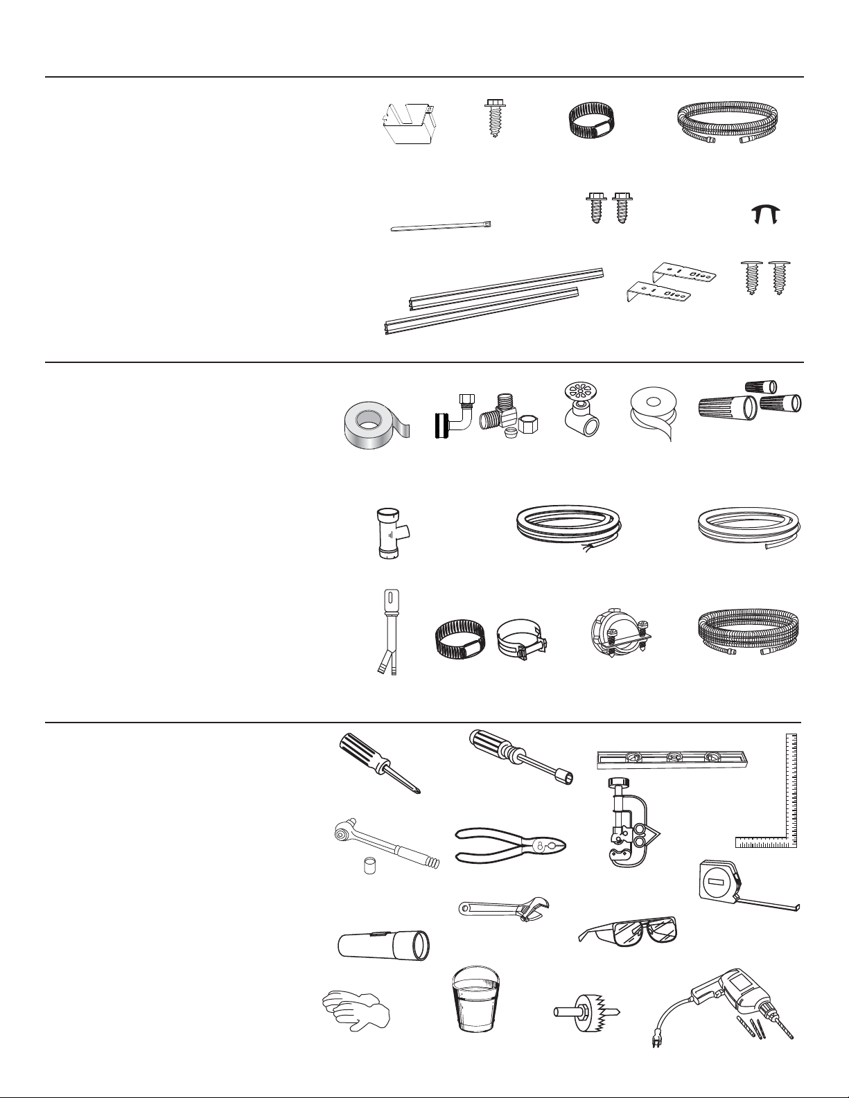
PARTS SUPPLIED
IN INSTALLATION PACKAGE:
• Junction box cover and #10 hex-head screw
• Hose clamp
• Drain hose (approximately 78" long)
• Drain hose hanger
• 2 #8-18 hex head screws to secure brackets to washer
tub frame
• 2 Plug buttons
• 2 side trim pieces (some models)
• 2 mounting brackets for wood countertops or side
cabinets
• 2 #8-18 x 5/8" Phillips special head screws, to secure
dishwasher to underside of countertop or to side
cabinets
• Literature, samples and/or coupons
MATERIALS YOU WILL NEED:
• Ferrule, compression nut and 90° elbow (3/8"NPT
external thread or dishwasher ¾” GHT on one
end, opposite end sized to fit water supply)
• Thread seal tape
• UL-listed wire nuts (3)
• Masking Tape
Masking Tape
(if applicable)
Junction
Box Cover
Drain Hose Hanger
90° Elbow,
Ferrule and
Compression Nut
#10
Hex-Head
Junction
Box Screw
1/2" long
Side Trim Pieces
(on some models)
Hose Clamp
#8 Hex-Head Mounting
Bracket Screws
Mounting
Brackets
Hand
6KXW2ȹ
Valve
Thread
Seal Tape
(if applicable)
Drain Hose
Plug Buttons
#8 Phillips
Special
Head Screws
5/8" long
Wire Nuts (3)
Materials Needed for
New Installations:
• Air gap for drain hose, if required
• Waste tee for house plumbing, if applicable
• Electrical cable or power cord
• Screw-type hose clamps
• Strain relief for electrical connection
• Hand shut-off valve (recommended)
• Water line–3/8" minimum, copper tubing or
GE Part # WX28X326, flexible braided hose
• GPF12L drain hose (12' long), if needed
TOOLS YOU WILL NEED:
• Phillips-head screwdriver
• 1/4" and 5/16" nutdriver
• 6" Adjustable wrench
• Level
• Carpenter's square
• Measuring tape
• Safety glasses
• Flashlight
• %XFNHWWRFDWFKZDWHUZKHQÀXVKLQJWKHOLQH
• 15/16" socket (optional for skid removal)
• Gloves
• Pliers
For New Installations Only:
• Tubing cutter
• Drill and appropriate bits
• Hole saw set
2
Air Gap
Phillips-Head
Screwdriver
15/16" Socket
Flashlight
Gloves
Waste Tee
Hose Clamps
Electrical Cable
(or Power Cord, if applicable)
1/4" and 5/16"
Nutdriver
Pliers
6"
Adjustable
Wrench
Bucket
Strain Relief
Level
Tubing Cutter
Safety Glasses
Hole Saw Set
Hot Water Line
Optional
12' Drain Hose
GPF12L
Carpenter's
Square
Measuring Tape
Drill and Bits
Installation Preparation
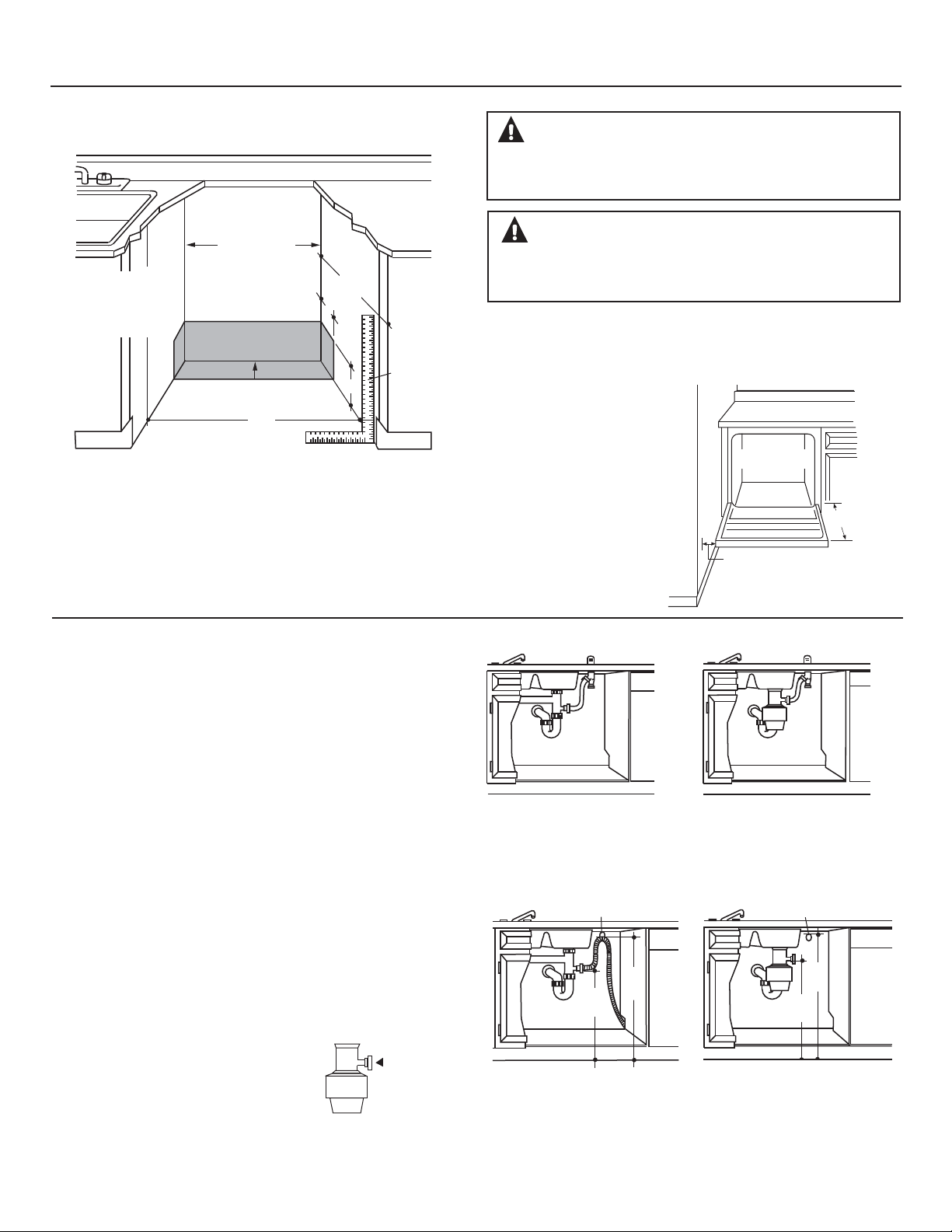
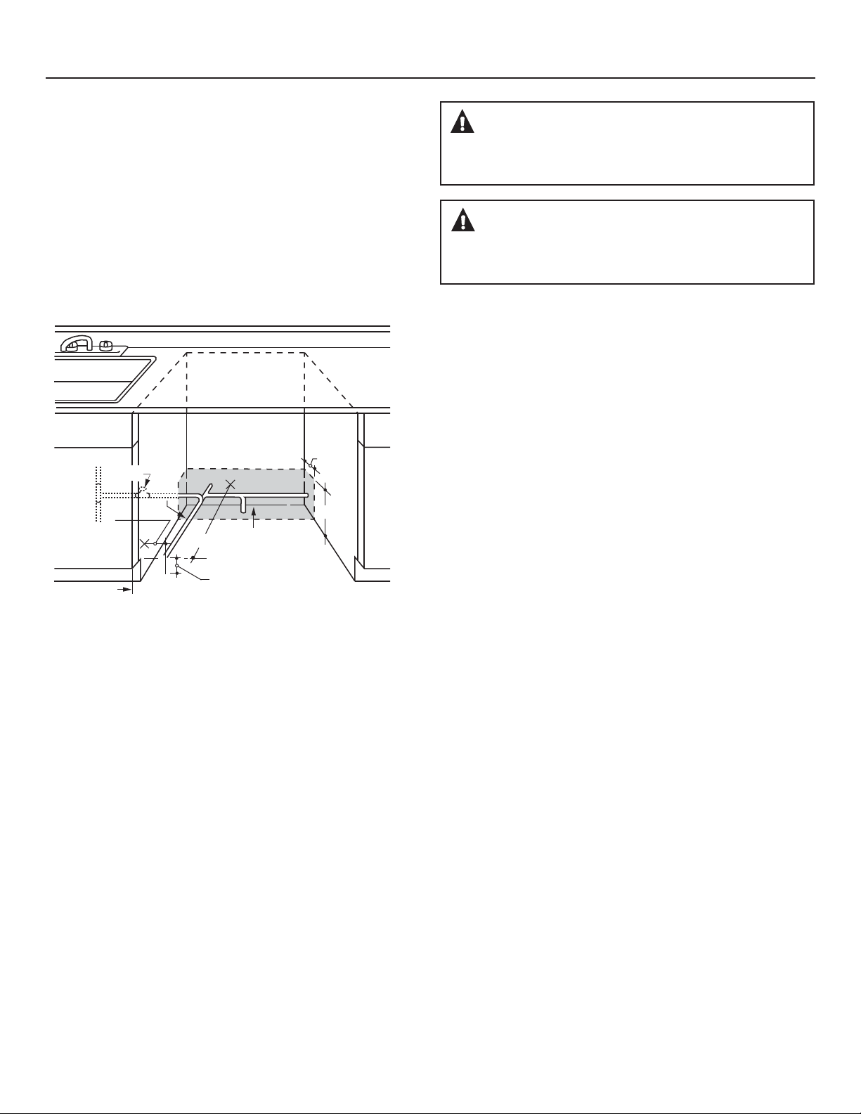
PREPARE DISHWASHER ENCLOSURE
This Wall Area
must be Free
of Pipes or
33-1/2” to 34-3/4”
Underside of
Countertop
to Floor
Figure A
+
34-1/2" 1/4"
Underside of
Countertop
to Floor
wires
Plumbing and Electric Service
Must Enter Inside This Area
24"
Min.
• The rough cabinet opening must be at least 24" deep, 24"
wide and approximately 34-1/2" high from floor to underside
of the countertop.
24"
Min.
4"
Cabinets
Square
6"
and
Plumb
WARNING:
7RUHGXFHWKHULVNRIHOHFWULFVKRFN¿UHRULQMXU\WRSHUVRQVWKH
installer must ensure that the dishwasher is completely enclosed at
the time of installation.
ADVERTENCIA:
Para reducir el riesgo de descarga eléctrica, incendio o lesiones a
personas, el instalador debe asegurarse de que el lavaplatos esté
completamente cerrado en el momento de la instalación.
• The dishwasher must be installed so that drain hose is no
more than 12' in length for proper drainage.
• The dishwasher must be fully enclosed on the top, sides and
back, and must not support any part of the enclosure.
CLEARANCES:
• When installed into a corner,
allow 2" min. clearance
between dishwasher and
adjacent cabinet, wall or other
appliances. Allow 28-3/8" min.
clearance from the front
of the dishwasher for door
opening. Figure B.
• Allow at least 6" between
dishwasher and range or
oven appliances.
Figure B
Countertop
Dishwasher
28-3/8"
Clearance for Door
Opening 2" Minimum
DRAIN REQUIREMENTS
• Follow local codes and ordinances.
• Do not exceed 12' distance to drain.
NOTE: Air gap must be used, if waste tee or disposer
connection is less than 18" above floor to prevent siphoning.
DETERMINE DRAIN METHOD
The type of drain installation depends on the following
questions.
• Do local codes or ordinances require an air gap?
• Is waste tee less than 18" above floor?
If the answer to either question is YES, Method 1 MUST
be used.
• If the answers are NO, either method may be used.
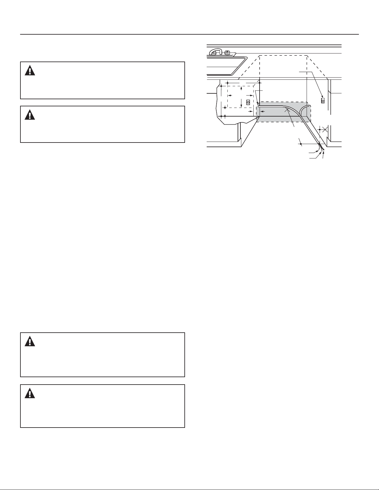
CABINET PREPARATION
• Drill a 1-1/2" diameter hole in the cabinet wall within
the shaded areas shown in Figure A for the drain hose
connection. The hole should be smooth with no sharp edges.
IMPORTANT – When
connecting drain line to disposer,
check to be sure that drain plug has
been removed. DISHWASHER WILL
NOT DRAIN IF PLUG IS LEFT IN PLACE.
Remove
Drain
Plug
Figure C
Method 1 – Air Gap with Waste Tee or Disposer
An air gap must be used when required by local codes and ordinances. The air gap must be installed according to manufacturer’s
instructions.
Drain Hose Hanger
32"
Min.
18"
Min.
Figure D
Method 2 – “High Drain Loop” with Waste Tee or Disposer
Drain Hose Hanger
32"
Min.
18"
Min.
Tip: Avoid unnecessary service call charges.
Always be sure disposer drain plug has been removed before
attaching dishwasher drain hose to the disposer.
3
Installation Preparation
PREPARE ELECTRICAL WIRING
WARNING:
FOR PERSONAL SAFETY: Remove house fuse or open circuit breaker
before beginning installation. Do not use an extension cord or
adapter plug with this appliance.
ADVERTENCIA:
PARA SEGURIDAD PERSONAL: Quite el fusible o abra el interruptor
de circuitos antes de comenzar la instalación. No utilice un cable
de extensión o un enchufe adaptador con este artefacto.
18"
6"
18"
Receptacle
Location
Area
6"
Alternate
Receptacle
Location
1-1/2" Dia. Hole (Max.)
3"
from
Cabinet
24"
from Wall
Electrical Requirements
• This appliance must be supplied with 120V, 60 Hz., and
connected to an individual properly grounded branch circuit,
protected by a 15- or 20-ampere circuit breaker or time-delay
fuse.
• Wiring must be 2 wire with ground and rated for 75°C (176°F).
• If the electrical supply does not meet the above requirements,
call a licensed electrician before proceeding.
Grounding Instructions–Permanent Connection
This appliance must be connected to a grounded metal,
permanent wiring system, or an equipment-grounding
conductor must be run with the circuit conductors and be
connected to the equipment-grounding terminal or lead on
the appliance.
Grounding Instructions–Power Cord Models
This appliance must be grounded. In the event of a malfunction
or breakdown, grounding will reduce the risk of electric shock
by providing a path of least resistance for electric current.
This appliance is equipped with a cord having an equipmentgrounding conductor and a grounding plug. The plug must
be plugged into an appropriate outlet that is installed and
grounded in accordance with all local codes and ordinances.
WARNING:
The improper connection of the equipment grounding conductor
FDQUHVXOWLQDULVNRIHOHFWULFVKRFN&KHFNZLWKDTXDOL¿HG
electrician or service representative if you are in doubt that
the appliance is properly grounded.
Ground
Figure E
For models equipped with power cord: Do not modify the plug
provided with the appliance; if it will not fit the outlet, have a
proper outlet installed by a qualified technician.
Cabinet Preparation & Wire Routing
• The wiring may enter the opening from either side, rear or the
floor within the shaded area illustrated above in Figure E and
defined in Figure A.
• Cut a 1-1/2" maximum diameter hole to admit the electrical
cable. Edges of hole should be smooth and rounded.
Permanent wiring connections may pass through the same
hole as the drain hose and hot water line, if convenient. If
cabinet wall is metal, the hole edge must be covered with a
bushing.
NOTE: Power cords with plug must pass through a separate
hole.
Electrical Connection to Dishwasher
Electrical connection is on the right front of dishwasher.
• For permanent connections the cable must be routed as
shown in Figure E. Cable must extend a minimum of 24" from
the rear wall.
• For power cord connections, install a 3-prong grounding
type receptacle in the sink cabinet rear wall, 6" min. or 18"
maximum from the opening, 6" to 18" above the floor.
• Use WD06X10020 Dishwasher Power Cord Kit.
Black
White
ADVERTENCIA:
La conexión inadecuada del conductor de conexión a tierra del
equipamiento puede provocar un riesgo de descarga eléctrica.
&RQVXOWHDXQHOHFWULFLVWDFDOL¿FDGRRUHSUHVHQWDQWHGHVHUYLFLR
técnico si tiene dudas sobre la correcta conexión a tierra del aparato.
4
Installation Preparation
PREPARE HOT WATER LINE
NOTE: GE recommends copper tubing for the water line, but if
\RXFKRRVHWRXVHÀH[LEOHKRVHXVH*(·VWX28X326ÀH[LEOH
braided hose.
• The water supply line (3/8” copper tubing or flexible braided
hose) may enter from either side, rear or floor within the
shaded area shown in Figure F.
• The water supply line may pass through the same hole as the
electrical cable and drain hose. Or, cut an additional 1-1/2"
diameter hole to accommodate the water line. If power cord
with plug is used, water line must not pass through power
cord hole.
CAUTION:
Do not remove wood base until you are ready to install the
dishwasher. The dishwasher will tip over when the door is
opened if base is removed.
PRECAUCIÓN:
No quite la base de madera hasta que esté listo para instalar el
lavaplatos. Si se quita la base, el lavaplatos se volcará cuando
se abra la puerta.
Hot
From
Cabinet
Cabinet Face
Figure F
Shut-off
Valve
2"
1-1/2" Dia.
Hole
19" From Wall
2" From Floor
4"
6"
Water Line Connection
• If using a flexible braided supply hose, label the hose with the
installation date to use as reference. Flexible braided hoses
should be replaced in 5 years.
• Turn off the water supply.
• Install a hand shut-off valve in an accessible location, such
as under the sink. (Optional, but strongly recommended and
may be required by local codes.)
• Water connection is on the left side of the dishwasher. Install
the hot water inlet line, using no less than 3/8" copper tubing
or a flexible braided hose. Route the line as shown in Figure F
and extend forward at least 19" from rear wall.
• Adjust water heater for 120°F to 140°F temperature.
• Flush water line to clean out debris.
• The hot water supply line pressure must be 20-120 PSI.
Turn page to begin dishwasher installation.
5
Dishwasher Installation
STEP 1: PREPARATION
Locate the items in the installation package:
• Screws
• Junction box cover
• Drain hose and clamp
• Mounting brackets
• Trim pieces (on some models)
• Drain hose hanger
• Owner's Manual
• Product samples and/or coupons
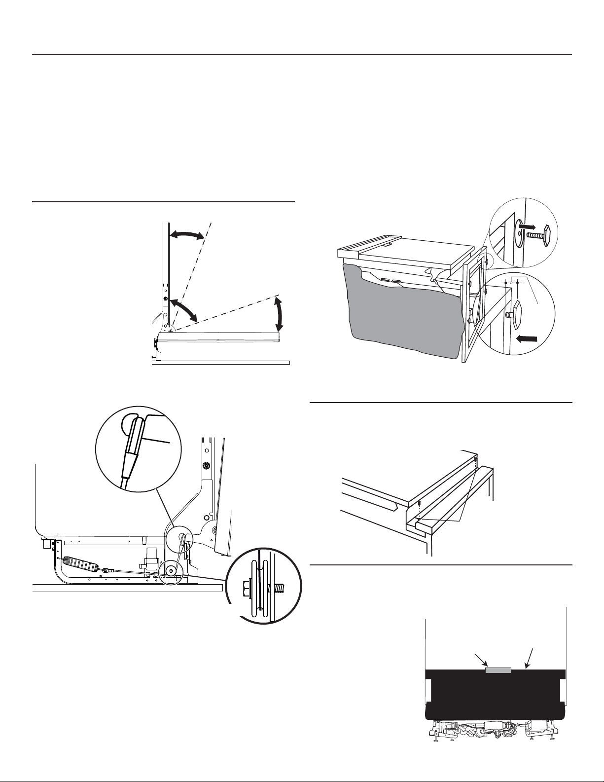
STEP 2: CHECK DOOR BALANCE
• With dishwasher on the
wood base, check the
door balance by opening
and closing the door.
• Door is properly balanced
if, when opened, it self
closes within 20° from
vertical, stays in position
from 20° to 70° and falls
fully open beyond 70°.
Door
closes
within
20°
Door stays in
position from
20° to 70°
Side View
Door falls fully
open beyond 70°
STEP 3: REMOVE WOOD BASE,
INSTALL LEVELING LEGS
IMPORTANT – 'RQRWNLFNRȺZRRGEDVH
Damage will occur.
• Move the dishwasher close to the installation location and lay
it on its back.
• Remove the 4 leveling legs on the underside of the wood base
with a 15/16" socket wrench.
• Discard base.
Approx.
1/2"
Figure H
• If necessary increase or decrease tension as shown. Latch
door and adjust both springs to the same tension setting to
correct balance.
Side View
Make sure
pulley cable
is within
pulley
shoulders
Figure G
Tip: Make sure door opens and closes smoothly.
Check door opening and closing. If door does not open easily or
falls too quickly, check spring cable routing. The cable is held in
place by “shoulders” on the pulley. Check to be sure cable has
not slipped over the pulley shoulders and is routed as shown.
Front View
• Screw leveling legs back into the dishwasher frame,
approximately 1/2" from frame as shown.
STEP 4: REMOVE TOEKICK
• Remove the 2 toekick screws and toekick. Set aside for use in
Step 22.
Toekick
Figure I
Remove 2
Toekick Screws
STEP 5: POSITION SOUND BARRIER
(on some models)
Skip this step if the sound
barrier is not assembled
to the dishwasher.
Lift the sound barrier and
tape to the door front with
masking tape. This will
hold the sound barrier up
and out of the way during
installation.
Tape
Sound Barrier
6
Bottom Front View
Dishwasher Installation
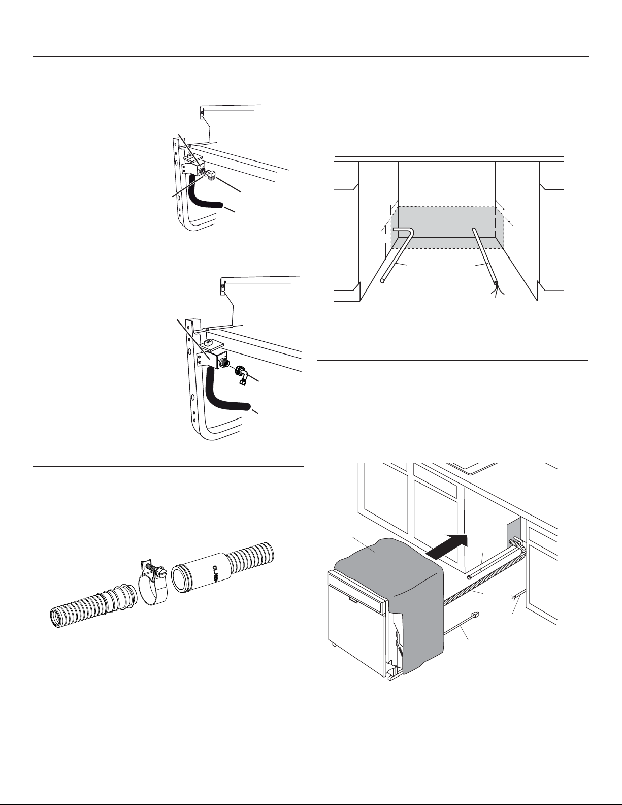
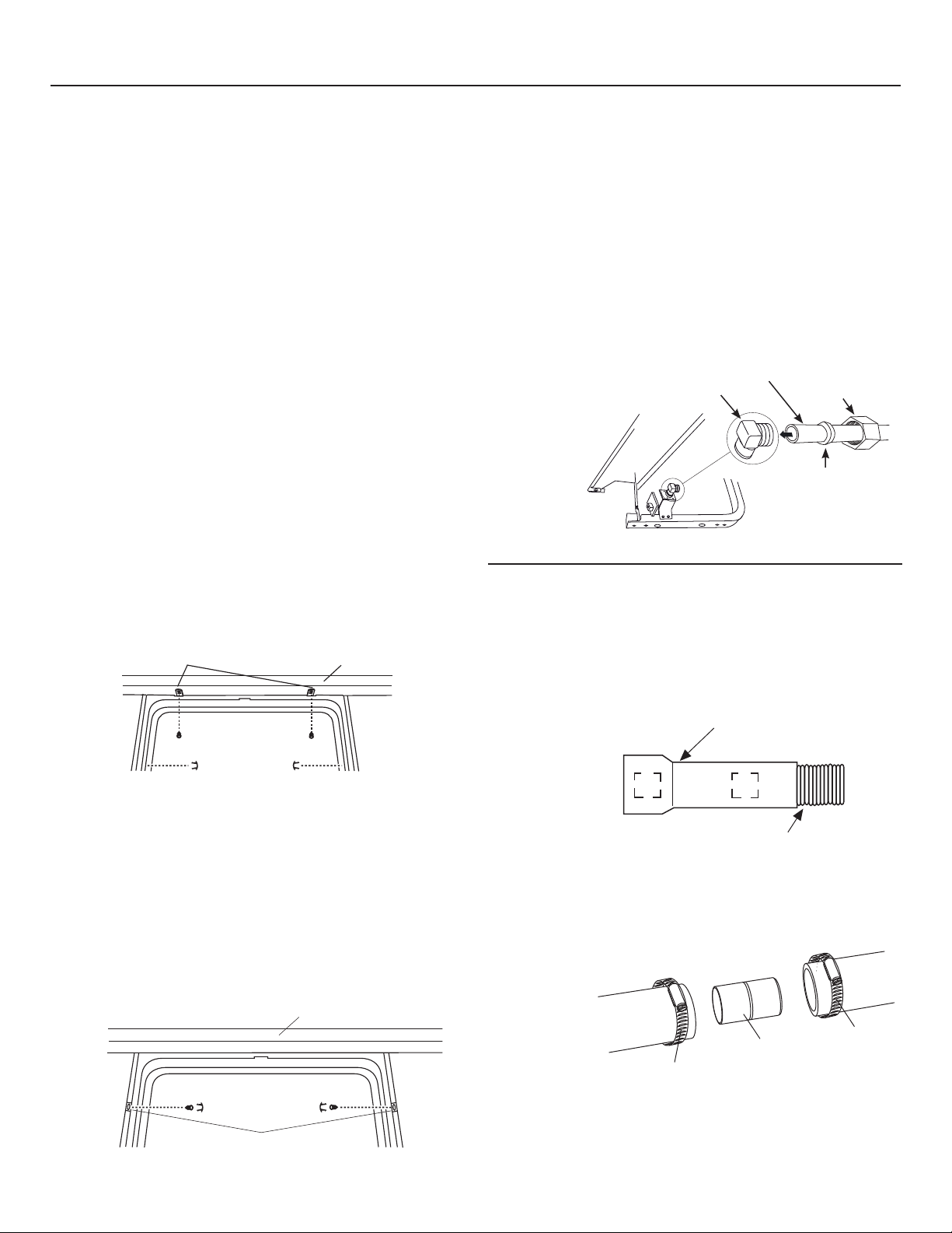
STEP 6: INSTALL 90° ELBOW
• Thread 90° elbow
onto the water valve.
Use thread seal tape
for elbows with 3/8"
NPT external threads.
• Do not overtighten
elbow. Water valve
bracket could
bend or water valve
fitting could break.
• Position the end of
the elbow to face the
rear of the dishwasher.
Water Valve
Bracket
Thread
Seal
Tape
Water Valve
Bracket
Front of Dishwasher
90° 3/8" NPT
Elbow
Fill Hose
OR
Front of dishwasher
STEP 8: POSITION WATER LINE
AND HOUSE WIRING
• Position water supply line and house wiring on the floor of
the opening to avoid interference with base of dishwasher
and components under dishwasher.
4"
6"
Figure M
4"
6"
Water
Line
House
Wiring
90° 3/4"
GHT Elbow
Fill Hose
Figure K
STEP 7: INSTALL DRAIN HOSE TO DRAIN
LOOP
Connect drain loop end to drain hose using the screw clamp
as shown in the figure.
Figure L
STEP 9:
INSTALL DRAIN HOSE,
THROUGH CABINET
• Position dishwasher in front of cabinet opening. Insert drain
hose into the hole in cabinet side. If a power cord is used,
guide the end through a separate hole.
Maximum Drain Hose
Length 10'
Insulation
Blanket
Water
Line
Drain
Hose
House
Wiring
Power Cord
(If Used)
Figure N
7LS3UHYHQWXQQHFHVVDU\VHUYLFHFDOOFKDUJHVIRU¿OOGUDLQRU
noise concerns.
Position utility lines so they do not interfere with anything
under or behind the dishwasher.
7
Dishwasher Installation
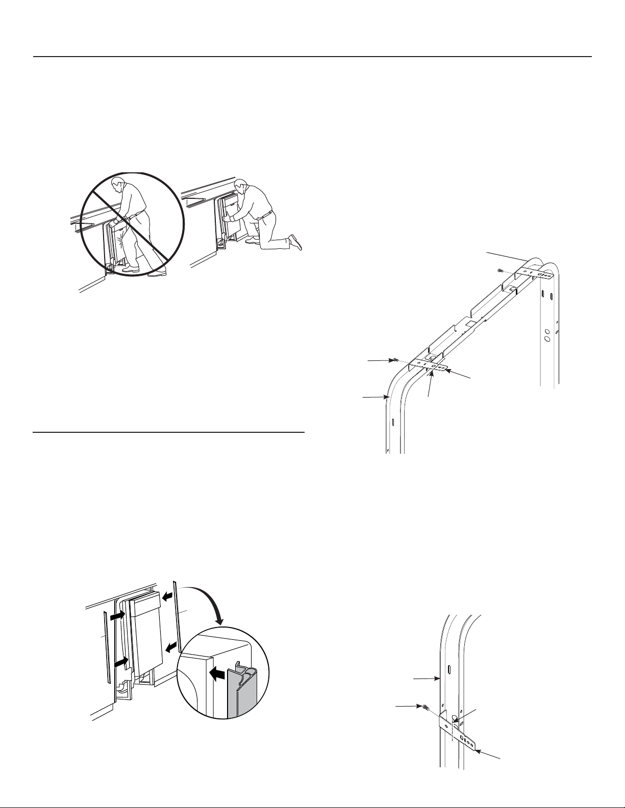
STEP 10: SLIDE DISHWASHER THREE-FOURTHS
OF THE WAY INTO CABINET
IMPORTANT – Do not push against front panel with
knees. Damage will occur.
• Grasp the sides of the front panel and slide dishwasher into
the opening a few inches at a time.
Do not push against
front door panel with
Figure O
• As you proceed, pull the drain hose through the opening
under the sink. Stop pushing when the dishwasher extends
about 6 inches forward of adjacent cabinets.
• Make sure drain hose is not kinked under or behind the
dishwasher.
• Make certain the house wiring, drain line and water line do
not interfere with components under dishwasher.
knee. Damage to the
door panel will occur.
STEP 12: INSTALL MOUNTING BRACKETS
You will need the mounting brackets and 2 #8 hex-head screws
set aside in Step 1.
You must install the mounting brackets onto the dishwasher
tub frame top or sides prior to sliding the dishwasher into place
under the countertop.
Install mounting brackets on top if the underside of
countertop is wood or wood-like material that accepts screws:
IMPORTANT - After installing brackets and before
closing the dishwasher door, adjust the brackets by bending
them up as needed, so that they do not contact the top of the
dishwasher door and cause damage.
Top Mounting
#8 Bracket
Screw
Bracket
Dishwasher
tub frame
Bend and break here
after installing if
counter has a short
overhang.
STEP 11: INSTALL TRIM PIECES
(on some models)
Skip this step if trim is not supplied with the dishwasher.
In this step you will need the trim pieces set aside in Step 1.
• Position the trim pieces so the lips face toward the
dishwasher door.
6HOHFWDWULPSLHFHDQGSUHVVLWRQWRWKHOHIWVLGHWXEÀDQJH
Start with the top edge and press the trim piece completely
RQWRWKHWXEÀDQJHDV\RXPRYHWRZDUGVWKHERWWRP5HSHDW
IRUWKHULJKWVLGHWXEÀDQJHWULPSLHFH
Trim
Strip
Trim
Strip
Figure P
If you would like to order the Trim Kit from GE Service, please
call 800.GE.Cares and request part number WD08X10094 for
BB models or WD08X10096 for WW or CC models.
Top View
• If you are installing the dishwasher under a counter with a
short overhang, the countertop brackets may extend beyond
the edge of the counter. If this is the case, remove the excess
length by repeatedly bending the brackets at the front notch
only until they break.
Install mounting brackets on sides if the countertop is
granite or similar material that will not accept wood screws:
%UHDNRȺIURQWSRUWLRQRIWKHWDEZLWKSOLHUVDWWKHORFDWLRQ
shown.
• Position the left-hand side bracket as shown. Repeat with the
right bracket.
Side Mounting
Dishwasher
tub frame
#8 Bracket
Screw
Bend and break
here if necessary
Bracket
8
Dishwasher Installation
STEP 13: PUSH DISHWASHER INTO
FINAL POSITION
• Check the tub insulation blanket, if equipped, to be sure it is
smoothly wrapped around the tub. It should not be “bunched
up” and it must not interfere with the door springs. If the
insulation is “bunched up” or interfering with the springs,
straighten and recenter the blanket prior to sliding the
dishwasher into its final position.
• Slide the dishwasher into the final position by pushing on the
sides of the door panel. Do not use a knee or push on the
center of the panel. If you do, damage to the panel will likely
result.
• The dishwasher is in the final position when the edges of
the front panel are flush with the adjacent cabinets and the
dishwasher is centered in the cabinet opening.
IMPORTANT – Before opening the dishwasher door,
be certain the edges of the dishwasher door panel are behind
the face of the adjacent cabinet and not up against the cabinet
face. Refer to Figure Q. If the dishwasher door is opened
when the edge of the door is against the face of the cabinet,
dishwasher door damage and cabinet damage will occur.
• Open and close the dishwasher door to be sure it operates
smoothly, and does not rub on the adjacent cabinet.
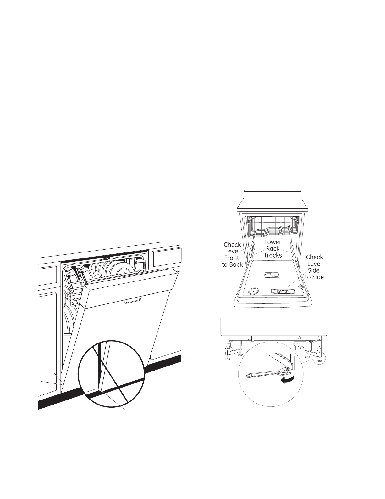
STEP 14: LEVEL DISHWASHER
IMPORTANT – Dishwasher must be level for proper
dish rack operation, wash performance and door operation.
The dishwasher must be leveled left to right and front to back.
This ensures the dish racks will not roll in or out on their own,
FLUFXODWLRQZDWHUZLOOÀRZWRWKHSXPSLQOHWDQGWKHGRRUZLOO
close without hitting the side of the tub.
• Remove the lower dish rack and place a level on the door and
lower rack track as shown in Figure R.
•
Adjust the level of the dishwasher by individually turning the 4
legs on the bottom of the dishwasher as illustrated in Figure S.
• The dishwasher is properly leveled when the level indicator is
centered left to right and front to back. Also, the dishwasher
door should close without hitting the side of the tub.
• Replace the lower rack.
Door
Fits and
Swings
Back
Behind
Cabinet
Frame
Correct
Alignment
Incorrect Alignment
will result in door damage
Figure Q
Tip: Prevent unnecessary service charges for panel damage
or wash performance.
Check dishwasher alignment prior to opening dishwasher door
to prevent panel damage.
Make sure utility lines are not trapped or crushed behind
dishwasher. Crushed lines will restrict water flow.
Door Catches
on Cabinet Frame
Figure R
Turn Legs
Figure S
Tip: Prevent unnecessary service charges. Verify dishwasher
is leveled.
Pull the dish racks half way out. They should stay put. Open
DQGFORVHWKHGRRU7KHGRRUVKRXOG¿WLQWKHWXERSHQLQJ
without hitting the side of the tub. If the racks roll on their own,
or the door hits the side of tub, relevel the dishwasher.
to Adjust
9
Dishwasher Installation
STEP 15: POSITION DISHWASHER, SECURE
TO COUNTERTOP OR CABINET
In this step you will need the 2 Phillips special head screws
from the screws set aside in Step 1.
The dishwasher must be secured to the countertop or the
cabinet sides. When the underside of the countertop is wood,
use Method 1. Use Method 2 when the underside of the
countertop is made of a material, such as granite, that will not
accept wood screws.
IMPORTANT – Prevent door panel and control
panel damage. Dishwasher must be positioned so the front
panel and control panel do not contact the adjacent cabinets
or countertop. Mounting screws must be driven straight and
flush. Protruding screw heads could scratch the door panel or
control panel and interfere with door operation.
Method 1
Secure dishwasher to underside of wood countertop.
• Recheck alignment of the dishwasher in the cabinet. Refer to
Steps 13 and 14. Door panel and/or control panel must not
hit cabinets or countertop.
• Fasten the dishwasher to the underside of the countertop
with the 2 Phillips special head screws. Refer to Figure T.
0DNHFHUWDLQVFUHZVDUHGULYHQVWUDLJKWDQGÀXVKWRSUHYHQW
panel damage.
• Install plug buttons to the side of the tub well in the holes
provided.
Brackets
Wood Countertop
STEP 16: CONNECT WATER SUPPLY
Connect water supply line to 90° elbow.
If using a flexible braided hose connection:
• Attach nut to 90° elbow using an adjustable wrench.
If using a copper tubing connection:
• Slide compression nut, then ferrule over end of water line.
• Insert water line into 90° elbow.
• Slide ferrule against elbow and secure with compression nut.
IMPORTANT – Check to be sure that door spring
DQGRUGRRUVSULQJFDEOHGRQRWUXERUFRQWDFWWKH¿OOKRVHRU
water supply line.
Test by opening and
closing the door.
Reroute the water
supply lines if a
rubbing noise or
interference
occurs.
Figure V
90° Elbow
Bottom Left Side
STEP 17: CONNECT DRAIN LINE
The molded end of the drain hose will fit 5/8" through 1"
diameter inlet ports on the air gap, waste tee or disposer.
• Determine size of inlet port.
• Cut drain hose connector on the marked line, if required,
WR¿WWKHLQOHWSRUW
Hot Water
Supply Line
Compression
Nut
Ferrule
Figure T
Method 2
Secure dishwasher to cabinet sides.
• Recheck alignment of the dishwasher in the cabinet. Refer to
Steps 13 and 14. Door panel and/or control panel must not
hit cabinets or countertop.
• Fasten the dishwasher to the adjacent cabinets with the 2
Phillips special head screws provided. Refer to Figure U. Make
FHUWDLQVFUHZVDUHGULYHQVWUDLJKWDQGÀXVKWRSUHYHQWSDQHO
damage.
• Install plug buttons to the side of the tub well in the holes
provided.
Granite Countertop
Figure U
Side Brackets
Cutting Line
1"
Figure W
IMPORTANT: Do not cut corrugated
• If a longer drain hose is required and you did not purchase
drain hose GPF12L, add up to 66" length for a total of 144"
(12 feet) to the factory-installed hose. Use 5/8" or 7/8" inside
diameter hose and a coupler to connect
the 2 hose ends.
Secure the
connection
with hose
clamps.
Figure X
NOTE: TOTAL DRAIN HOSE LENGTH MUST NOT EXCEED 12 FEET
FOR PROPER DRAIN OPERATION.
7^bT2[P\_
5/8"
portion of hose
2^d_[Ta
7^bT2[P\_
10
 Loading...