

GE GDF510PGRWW OWNER’S MANUAL
Built-In DishwashersInstallation Instructions
See your Owner’s Manual for details on how to contact us regarding installation questions
BEFORE YOU BEGIN
Read these instructions completely and carefully.
WARNING
• Remove all power leading to the appliance from the
circuit breaker or fuse box before beginning installation.
Failure to do so can result in a risk of electrical shock.
•
To reduce the risk of electric shock, fire, or injury to persons,
the installer must ensure that the dishwasher is completely
enclosed at the time of installation.
• The improper connection of the equipment grounding
conductor can result in a risk of electric shock. Check
with a qualified electrician or service representative
if you are in doubt that the appliance is properly
grounded. If house wiring is not 2-wire with ground, a
ground must be by the installer. When house wiring
is aluminum, be sure to use UL-Listed anti-oxidant
compound and aluminum-to-copper connectors.
•
To reduce the risk of electric shock, fire, or injury to persons,
the installer should check to ensure that wires are not pinched
or damaged, the house wiring is attached to the junction box
bracket through a strain relief, and all electrical connections
made at the time of install (wire nuts) are contained inside of
the junction box cover.
ADVERTENCIA
• Retire todos los conductores de corriente del
electrodoméstico de disyuntor o de la caja del fusible
antes de comenzar con la instalación. Si no cumple con
esto, se podrá producir el riesgo de descargas eléctricas.
• Para reducir el riesgo de descarga eléctrica, incendio
o lesiones a personas, el instalador debe asegurarse
de que el lavaplatos esté completamente cerrado en
el momento de la instalación.
• La conexión inadecuada del conductor de conexión a
tierra del equipamiento puede provocar un riesgo de
descarga eléctrica. Consulte a un electricista calificado
o representante de servicio técnico si tiene dudas
sobre la correcta conexión a tierra del aparato. Si el
cableado doméstico no cuenta con un cable de 2 hilos
con conexión a tierra, un instalador debe realizar una
conexión a tierra. Cuando el cableado doméstico es de
aluminio, asegúrese de usar un compuesto antioxidante
y conectores de aluminio a cobre aprobados por UL.
• Para reducir el riesgo de descarga eléctrica, incendio
o lesiones a personas, el instalador deberá realizar un
control para asegurar que los cables no estén pellizcados
ni dañados, que el cableado del hogar esté conectado a la
ficha de la caja de empalmes a través de un amortiguador
de refuerzo, y que todas las conexiones eléctricas
realizadas en el momento de la instalación (tuercas para
cables) estén dentro de la tapa de la caja de empalmes.
FOR YOUR SAFETY
Read and observe all WARNINGS and CAUTIONS
shown throughout these instructions.
While performing installations described in this booklet,
gloves, safety glasses or goggles should be worn.
IMPORTANT – Observe all governing codes and ordinances.
• Note to Installer – Be sure to leave these instructions
for the consumer’s and local inspector’s use.
• Note to Consumer – Keep these instructions with
your Owner’s Manual for future reference.
• Skill Level – Installation of this dishwasher requires
basic mechanical, electrical and plumbing skills.
Proper installation is the responsibility of the
installer. Product failure due to improper installation
is not covered under the GE Appliances Warranty.
See warranty information.
• Completion Time – 1 to 3 Hours. New installations
require more time than replacement installations.
IMPORTANT – The dishwasher MUST be installed to allow
for future removal from the enclosure if service is required.
Care should be exercised when the appliance is installed
or removed,
power supply cord.
If you received a damaged dishwasher, you should
immediately contact your dealer or builder.
Optional Accessories – See the Owner’s Manual for
available custom panel kits.
Your dishwasher is a water heating appliance.
CAUTION
not fully installed. When opening the door prior to the
dishwasher being fully installed, hold the top of the
dishwasher securely with one hand and hold the door
with the other hand. Gloves should be worn.
PRECAUCIÓN
adelante cuando no se encuentre completamente
instalado. Al abrir la puerta antes de haber instalado
completamente el lavavajillas, sostenga la parte superior
del lavavajillas de forma segura con una mano y sostenga
la puerta con la otra mano. Se deberán usar guantes.
to reduce the likelihood of damage to the
Opening the door will cause the
dishwasher to tip forward when it is
Abrir la puerta hará que el
lavavajillas se incline hacia
READ CAREFULLY
KEEP THESE INSTRUCTIONS
31-4000220 Rev 1 08-20 GEA
Installation Preparation
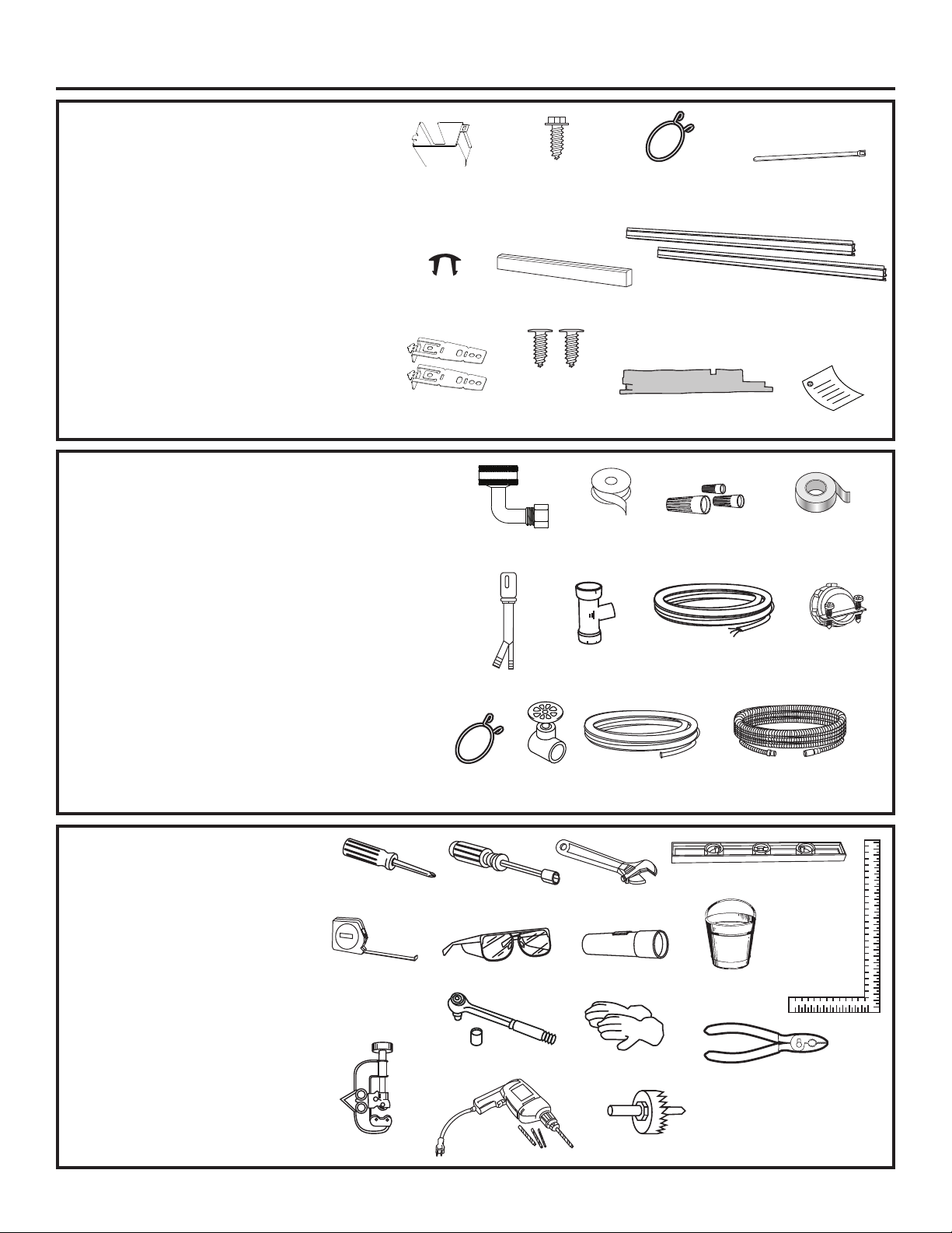
PARTS SUPPLIED IN
INSTALLATION PACKAGE:
• Junction box cover
• #10 hex-head screw
• Hose clamp
• Drain hose hanger
• 2 Plug buttons
• Toekick (pre-installed on some models)
• 2 Tub trim pieces (on some models)
• 2 Mounting brackets for wood countertops
or side cabinets
• 2 #8-18 x 5/8” Phillips special head screws,
to secure dishwasher to underside of
countertop or to side cabinets
• Insulation pieces (on some models)
• Literature, samples and/or coupons
MATERIALS YOU WILL NEED:
• ´*+7*DUGHQ+RVH7KUHDGÛHOERZLQFOXGLQJ
gasket) - with opposite end sized to fit Hot Water Line
• Thread seal tape
• UL-listed wire nuts (3)
• Masking tape
Materials For New Installations Only:
• Air gap for drain hose, if required
• Waste tee for house plumbing, if applicable
• Electrical cable or Power Cord Kit WX09X70910 (5’ 5” long)
or WX09X70911 (7’ 11” long) depending on installation.
• Strain relief for electrical connection
• Hose clamps
• Hand shut-off valve (recommended)
• Hot Water Line–3/8” minimum, copper tubing (including
ferrule, compression nut) or GE Appliances Part #
WX28X326, flexible braided hose.
• WD24X10065 drain hose (12’ long) or WD24X10062
drain hose (4’ long), if needed.
Junction
Box Cover
Plug
Buttons
Mounting
Brackets
Clamps
Head Screws
GHT 90°Elbow
Air Gap
Hose
Shut-Off
#10
Hex-Head
Junction
Box Screw
3/8" long
Toekick
#8 Phillips
Special
5/8" long
(if applicable)
Waste Tee
Hand
Valve
Hose Clamp
Thread
Seal Tape
Hot
Water
Line
Tub Trim Pieces
(on some models)
Insulation
(on some models)
Wire Nuts (3)
Electrical Cable
(or Power Cord,
if applicable)
12' Drain Hose - WD24X10065
4’ Drain Hose - WD24X10062
Drain Hose Hanger
Literature
Masking Tape
Strain
Relief
Optional -
TOOLS YOU WILL NEED:
• Phillips-head screwdriver
• 1/4” and 5/16” nutdriver
• 6” Adjustable wrench
• Level
• Carpenter’s square
• Measuring tape
• Safety glasses
• Flashlight
• Bucket to catch water when flushing the line
• 15/16” socket
• Gloves
• Pliers
For New Installations Only:
• Tubing cutter
• Drill and appropriate bits
• Hole saw set
Phillips-Head
Screwdriver
Measuring Tape
Tubing Cutter
1/4” and 5/16”
Nutdriver
Safety Glasses
15/16” Socket
Drill and Bits
2
6” Adjustable
Wrench
Flashlight
Gloves
Hole Saw Set
Bucket
Level
Carpenter’s
Square
Pliers
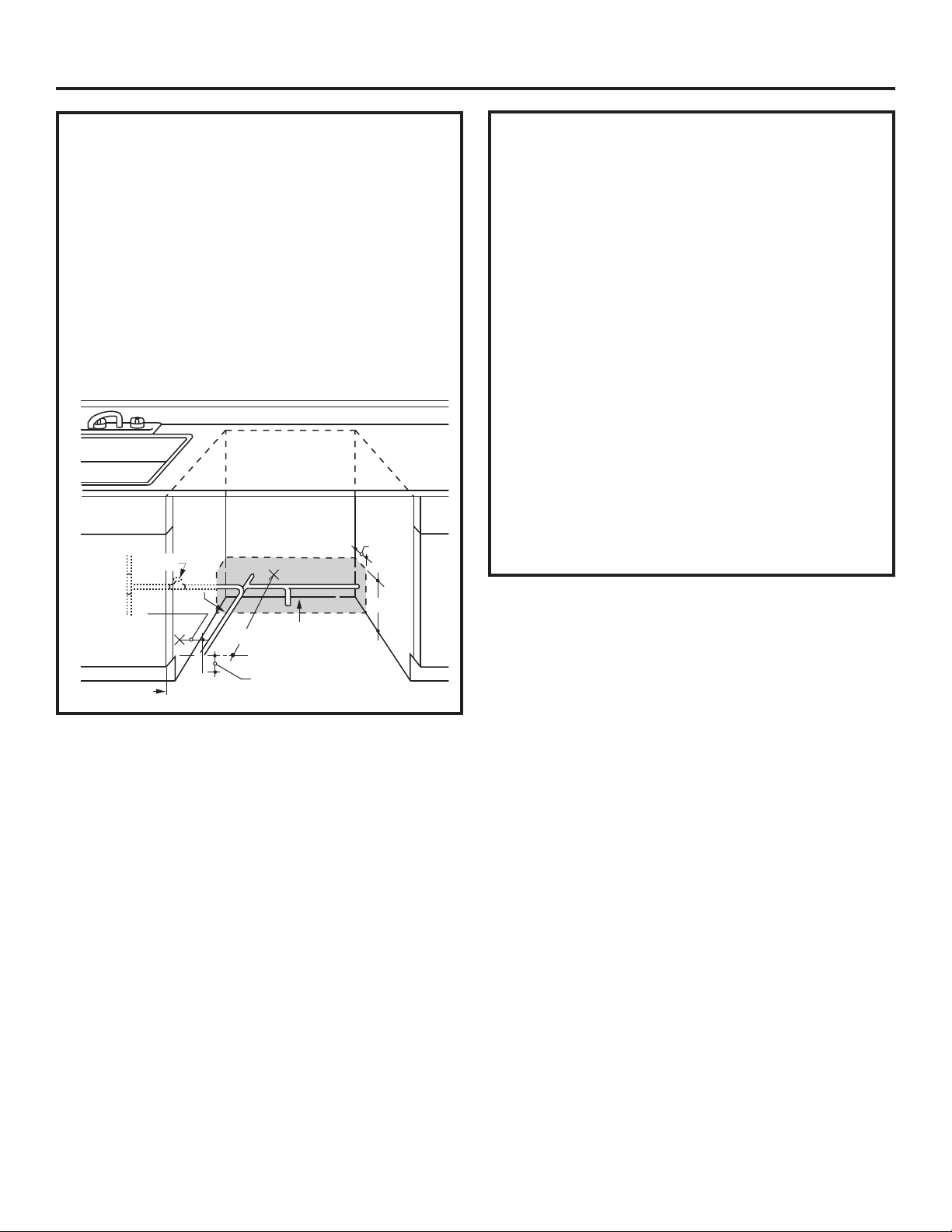
Installation Preparation
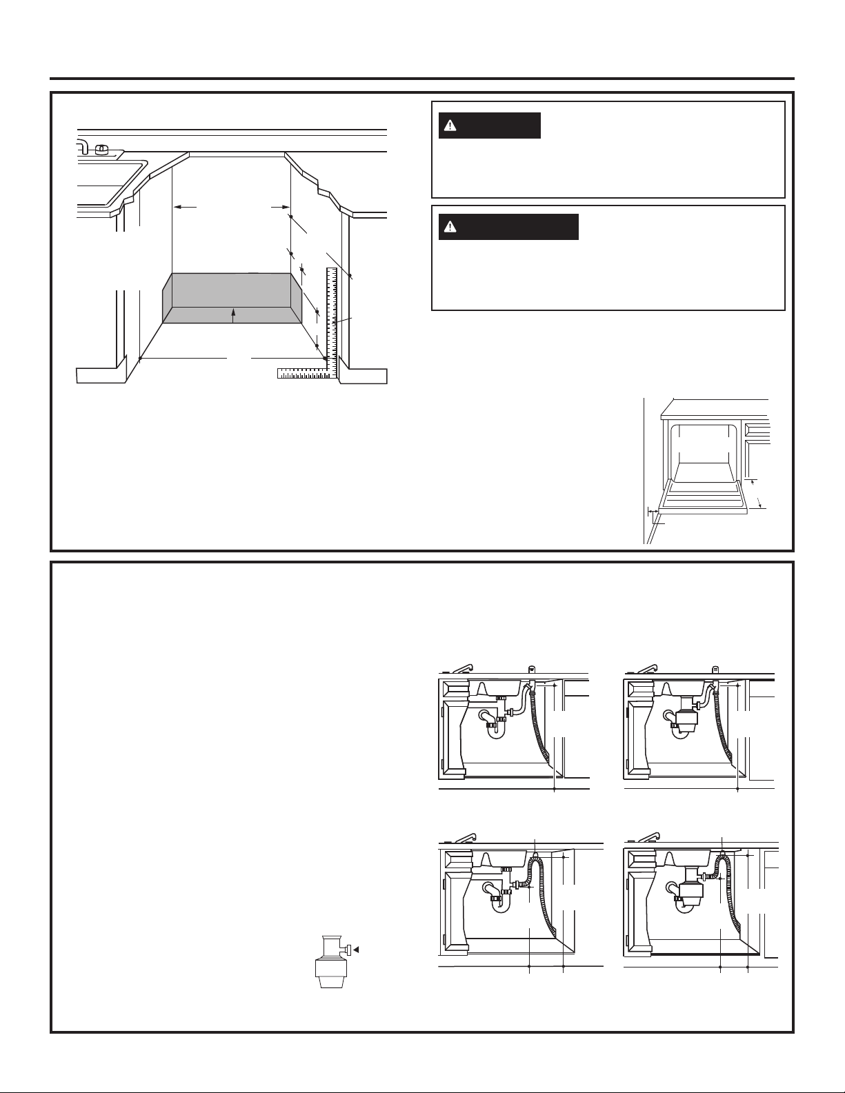
PREPARE DISHWASHER ENCLOSURE
This Wall Area
Must be Free
34-1/2”+1/4”
33-1/2” to 34-3/4”
Underside of
Underside of
Countertop
Countertop
to Floor
to Floor
of Pipes and
Wires
Plumbing and Electric Service
Must Enter Inside This Area
24”
Min.
• The rough cabinet opening must be at least 24” deep,
24” wide and approximately 34-1/2” high from floor to
underside of the countertop.
• The dishwasher must be installed so that drain hose is
no more than 16’ in length for proper drainage.
• The dishwasher must be fully enclosed on the top,
sides and back, and must not support any part of the
enclosure.
24”
Min.
4”
Cabinets
Square
6”
and
Plumb
WARNING
To reduce the risk of electric shock, fire, or injury to
persons, the installer must ensure that the dishwasher
is completely enclosed at the time of installation.
ADVERTENCIA
Para reducir el riesgo de descarga eléctrica, incendio
o lesiones a personas, el instalador debe asegurarse
de que el lavaplatos esté completamente cerrado en el
momento de la instalación.
DISHWASHER HANDLE DIMENSION: The dishwasher
door should be flush with the cabinet. For models with
a handle, the total depth (with handle) is 26-1/4” max.
depending on the model. Locate the Quick Specs document
online for more dishwasher dimensions.
CLEARANCES: When installed into
a corner, allow 2” min. clearance
between dishwasher and adjacent
cabinet, wall or other appliances.
Allow 25-1/2” min. clearance from
the front of the dishwasher for
door opening.
Countertop
Dishwasher
25-1/2"
Clearance for Door
Opening 2" Minimum
DRAIN REQUIREMENTS
• Follow local codes and ordinances.
• Do not exceed 16’ distance to drain.
NOTE : Air gap must be used if waste tee or disposer
connection is less than 18” above floor to prevent siphoning.
DETERMINE DRAIN METHOD
The type of drain installation depends on the following
questions.
• Do local codes or ordinances require an air gap?
• Is waste tee less than 18” above floor?
If the answer to either question is YES, Method 1
MUST be used.
•
If the answers are NO, either method may be used.
CABINET PREPARATION
• Drill a 1-1/2” diameter hole in the cabinet wall within
the shaded areas shown in PREPARE DISHWASHER
ENCLOSURE section for the drain hose connection.
The hole should be smooth with no sharp edges.
IMPORTANT – When connecting
drain line to disposer, check to be sure
that drain plug has been removed.
DISHWASHER WILL NOT DRAIN IF
PLUG IS LEFT IN PLACE.
Remove
Drain
Plug
Method 1 – Air Gap with Waste Tee or Disposer
An air gap must be used when required by local codes
and ordinances. The air gap must be installed according
to manufacturer’s instructions.
72”
max.
72”
max.
Method 2 – “High Drain Loop” with Waste Tee or Disposer
Drain Hose Hanger
32” min. 72” max.
18”
min.
Drain Hose Hanger
32” min. 72” max.
18”
min.
Tip: Avoid unnecessary service call charges.
Always be sure disposer drain plug has been removed
before attaching dishwasher drain hose to the disposer.
3
Installation Preparation
PREPARE ELECTRICAL WIRING
WARNING
Remove all power leading to the
appliance from the circuit breaker or
fuse box before beginning installation. Failure to do so
can result in a risk of electrical shock.
ADVERTENCIA
Retire todos los conductores de
corriente del electrodoméstico
de disyuntor o de la caja del fusible antes de comenzar
con la instalación. Si no cumple con esto, se podrá
producir el riesgo de descargas eléctricas.
ELECTRICAL REQUIREMENTS
Be sure that the electrical connection and wire size are adequate
and in conformance with the National Electric Code, ANSI/
NFPA
70 – latest edition, and all local codes and ordinances.
This appliance must have:
• 120V, 60Hz, AC-only, 15-ampere or 20-ampere, fused
electrical supply.
•
Wiring must be 2 wire with ground and rated for 75°C (167°F).
• If the electrical supply does not meet the above
requirements, call a licensed electrician before proceeding.
It is recommended to have:
• A circuit breaker or time-delay fuse.
• A properly grounded individual branch circuit.
Grounding Instructions–Permanent Connection
This appliance must be connected to a grounded metal,
permanent wiring system, or an equipment-grounding
conductor must be run with the circuit conductors and be
connected to the
equipment-grounding terminal or lead on
the appliance.
Grounding Instructions–Power Cord Models
This appliance must be grounded. In the event of a
malfunction or breakdown, grounding will reduce the risk
of electric shock by providing a path of least resistance
for electric current. This appliance is equipped with a cord
having an equipment-grounding conductor and a grounding
plug. The plug must
be plugged into an appropriate outlet
that is installed and grounded in accordance with all local
codes and ordinances.
WARNING
The improper connection of the
equipment grounding conductor can
result in a risk of electric shock. Check with a qualified
electrician or service representative if you are in doubt that
the appliance is properly grounded. Do not modify the plug
provided with the appliance; if it will not fit the outlet, have
a proper outlet installed by a qualified technician.
ADVERTENCIA
La conexión inadecuada del
conductor de conexión a
tierra del equipamiento puede provocar un riesgo de
descarga eléctrica. Consulte a un electricista calificado
o representante de servicio técnico si tiene dudas sobre
la correcta conexión a tierra del aparato. No modifique el
enchufe que se suministra con el aparato; si no calza en el
tomacorrientes, haga que un técnico calificado le instale
un tomacorrientes adecuado.
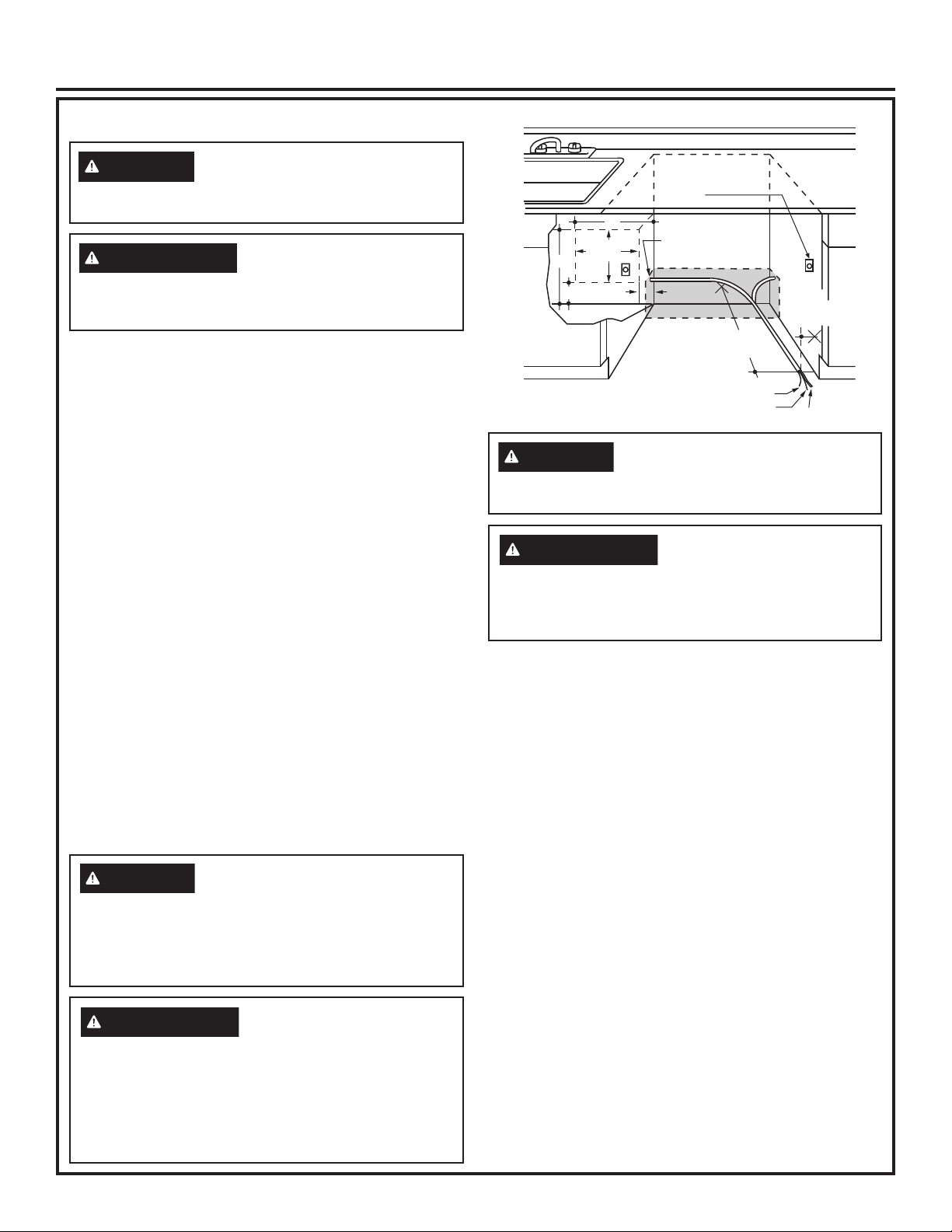
Alternate Receptacle
Location in Adjacent
Cabinet
18"
Receptacle
Location
18"
Area
6"
WARNING
1-1/2" Dia. Hole (Max.)
6"
24"
from Wall
Ground
Black
3"
from
Cabinet
White
For models equipped with power
cord: Do not modify the plug
provided with the appliance; if it will not fit the outlet,
have a proper outlet installed by a qualified technician.
ADVERTENCIA
Con los modelos equipados
con cable de corriente: No
modifique el enchufe provisto con el electrodoméstico;
si no coincide con el tomacorriente, solicite la instalación
de un tomacorriente apropiado a un electricista
calificado.
Cabinet Preparation & Wire Routing
•
The wiring may enter the opening from either side, rear
or the floor within the shaded area illustrated above
in figure and defined in PREPARE DISHWASHER
ENCLOSURE section.
• Cut a 1-1/2" maximum diameter hole to admit the
electrical cable. Edges of hole should be smooth and
rounded. Permanent wiring connections may pass
through the same hole as the drain hose and hot water
line, if convenient. If cabinet wall is metal, the hole
edge must be covered with a bushing.
NOTE:
Power cords with plug must pass through a
separate hole in the cabinet.
Electrical Connection to Dishwasher
Electrical connection is on the right front of dishwasher.
• For permanent connections the cable must be routed
as shown in figure. Cable must extend a minimum of
24" from the rear wall.
• For power cord connections, install a 3-prong
grounding type receptacle in the sink cabinet rear wall,
6" min. or 18" maximum from the opening, 6" to 18"
above the floor.
• Use only WX09X70910 (5’ 5” long) or WX09X70911 (7’
11” long) Dishwasher Power Cord Kit. Do not use an
extension cord or adapter plug with this appliance.
4
Installation Preparation
PREPARE HOT WATER LINE
NOTE: We recommend copper tubing for the water
line, but if you choose to use flexible hose, use GE
Appliances WX28X326, flexible braided hose.
• The water supply line (3/8” copper tubing or flexible
braided hose) may enter from either side, rear or
floor within the shaded area shown in figure.
• The water supply line may pass through the same
hole as the electrical cable and drain hose. Or, cut
an additional 1-1/2" diameter hole to accommodate
the water line. If power cord with plug is used, water
line must not pass through power cord hole.
1-1/2”
Hot
Cabinet
Shut-off
Valve
2"
From
Dia.
Hole
19" From Wall
4"
6"
Water Line Connection
• If using a flexible braided supply hose, label
the hose with the installation date to use as
reference. Flexible braided hoses, elbows and
gaskets should be replaced in 5 years.
• Turn off the water supply.
• Install a hand shut-off valve in an accessible
location, such as under the sink. (Optional, but
strongly recommended and may be required by local
codes.)
• Water connection is on the left side of the
dishwasher. Install the hot water inlet line, using no
less than 3/8” copper tubing or a flexible braided
hose. Route the line as shown in PREPARE HOT
WATER LINE section and extend forward at least
19” from rear wall.
• Adjust water heater for 120°F to 140°F temperature.
• Flush water line to clean out debris.
• The hot water supply line pressure must be 20-120
PSI.
Turn page to begin dishwasher installation.
Cabinet Face
2" From Floor
5
Dishwasher Installation
STEP 1
PREPARATION
Locate the items in the installation package:
• Screws
• Junction box cover
• Drain hose and clamp
• Mounting brackets
• Trim pieces (on some models)
• Drain hose hanger
• Insulation pieces (some models)
• Toekick (pre-installed on some models)
• Owner’s Manual
• Product samples and/or coupons
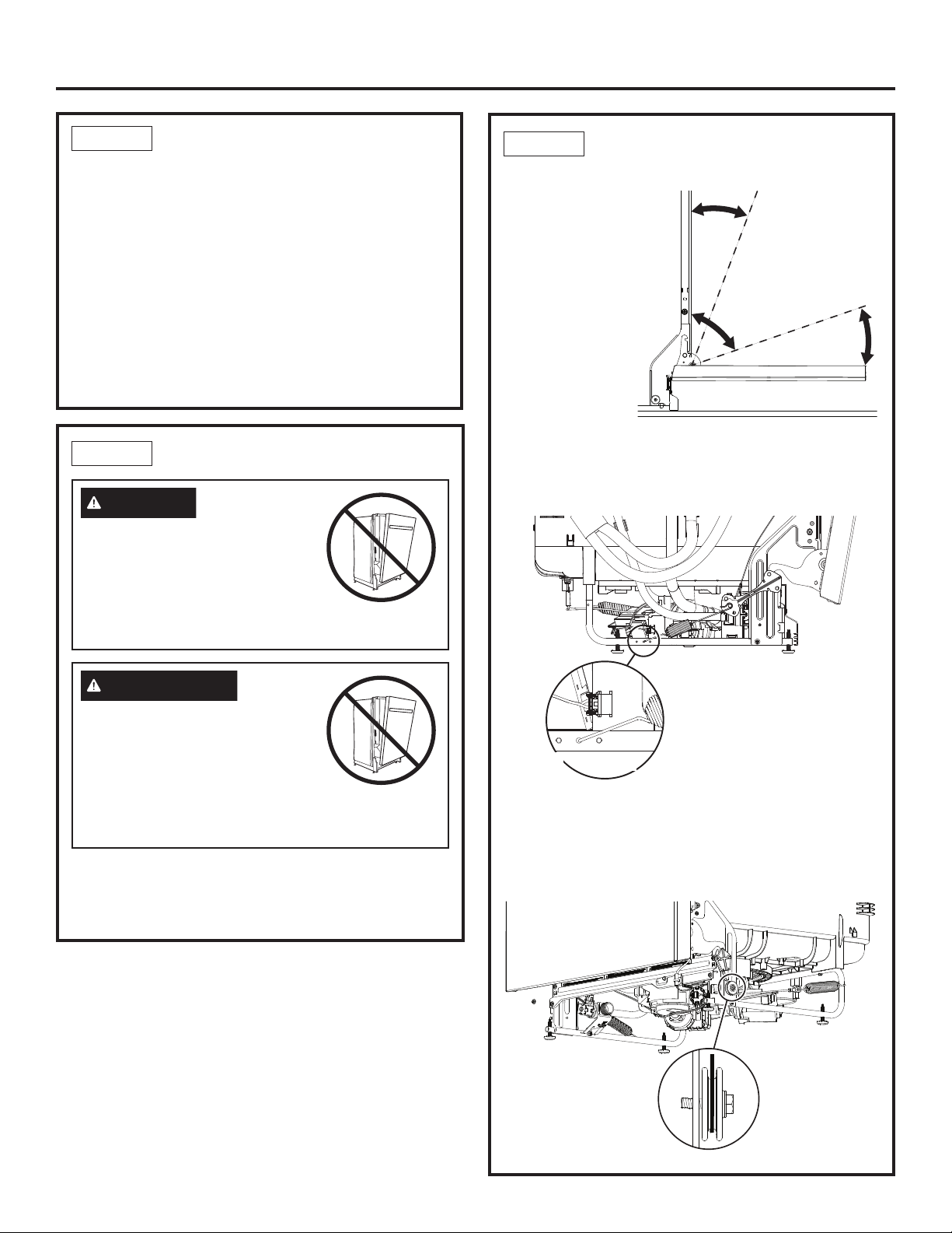
STEP 2
CHECK DOOR BALANCE
CAUTION
Opening the door will cause the
dishwasher to tip forward when it is
not fully installed. When opening the
door prior to the dishwasher being
fully installed, hold the top of the
dishwasher securely with one hand and hold the door
with the other hand. Gloves should be worn.
STEP 2
CHECK DOOR BALANCE
(CONT.)
• Door is properly
balanced if,
when opened, it
self closes within
20° from vertical,
stays in position
from 20° to 70°
and falls fully
open beyond 70°.
• If necessary
increase or
decrease tension
as shown. Latch
door and adjust
left spring tension on the side of the dishwasher to
correct balance. You will need to use a screwdriver to
knock out the adjustment holes on the rail.
NOTE: The right side spring is not adjustable.
Side
View
Door
closes
within
20°
Door stays in
position from
20° to 70°
Door falls fully
open beyond 70°
Side View
PRECAUCIÓN
Abrir la puerta hará que el lavavajillas
se incline hacia adelante cuando
no se encuentre completamente
instalado. Al abrir la puerta antes de
haber instalado completamente el
lavavajillas, sostenga la parte superior del lavavajillas
de forma segura con una mano y sostenga la puerta
con la otra mano. Se deberán usar guantes.
To check the door balance, hold the top of the
dishwasher firmly.
• Check the door balance by opening and closing the
door.
Increase
Tension
Decrease
Tension
Tip: Make sure door opens and closes smoothly.
Check door opening and closing. If door does not open
easily or falls too quickly, check spring cable routing.
The cable is held in place by “shoulders” on the pulley.
Check to be sure cable has not slipped over the pulley
shoulders and is routed as shown.
Make sure
pulley cable
is within
pulley
shoulders
Front View
6
Dishwasher Installation
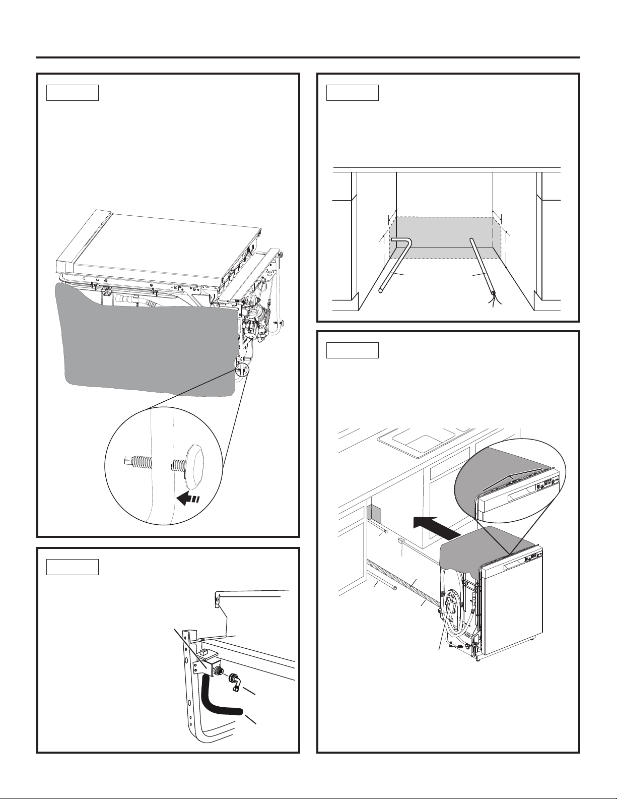
STEP 3
• Move the dishwasher close to the installation location
and lay it on its back. NOTE: Do not place the
dishwasher on its side.
• Discard base.
• With 15/16” socket wrench adjust leveling legs into
the dishwasher frame, approximately 1/2” from frame
as shown.
ADJUST LEVELING LEGS
Approx.
1/2”
STEP 5
POSITION WATER LINE
AND HOUSE WIRING
• Position water supply line and house wiring on the
floor of the opening to avoid interference with base
of dishwasher and components under dishwasher.
4"
6"
STEP 6
4"
6"
Water
Line
INSTALL DRAIN HOSE,
House
Wiring
THROUGH CABINET
• Position dishwasher in front of cabinet opening.
Insert drain hose into the hole in cabinet side. If
a power cord is used, guide the end through a
separate cabinet opening.
STEP 4
• Thread 3/4” GHT 90°
elbow onto the water
valve. Ensure rubber
gasket is located
between valve and
elbow.
• Do not overtighten
elbow. Water valve
bracket could bend or
water valve fitting could
break.
• Position the end of the
elbow to face the rear
of the dishwasher.
INSTALL 90° ELBOW
Water
Valve
Bracket
Front of dishwasher
90° Elbow
Fill Hose
Pull insulation
blanket over
collar
House
Wiring
Power Cord
(If used)
Drain
Water
Line
Ensure drain hose is not
twisted or pinched
Maximum drain hose
length is 16' from the
rear of the dishwasher
Do not disconnect or remove high
drain loop from left side of dishwasher
Tip: Prevent unnecessary service call charges for
fill, drain or noise concerns.
Position utility lines so they do not interfere with
anything under or behind the dishwasher.
Reposition the insulation blanket over the collar, as
shown.
Hose
Insulation
Blanket
7
Dishwasher Installation
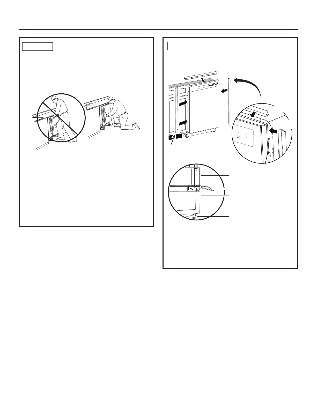
STEP 7
SLIDE DISHWASHER
THREE-FOURTHS OF
THE WAY INTO CABINET
IMPORTANT – Do not push against front panel with
knees. Damage will occur.
• Grasp the sides of the front panel and slide
dishwasher into the opening a few inches at a time.
Do not push against
front door panel with
knee. Damage to the
door panel will occur.
• As you proceed, pull the drain hose through the
opening under the sink. Stop pushing when the
dishwasher extends about 6 inches forward of
adjacent cabinets.
• Make sure drain hose is not kinked under or behind
the dishwasher.
• Make certain the house wiring, drain line and
water line do not interfere with components under
dishwasher.
STEP 8
In this step you will need the trim pieces set aside in Step 1.
(on some models)
Side Trim
Top
View
• Select the top trim piece and line up center to the
top latch. Press the trim piece onto the tub flange
moving from one side to the other.
• Select the left trim piece. Align top edge with the top
trim and press it onto the left side of the tub flange
moving from the top to the bottom. Repeat for the
right side tub flange trim piece.
INSTALL TRIM PIECES
Top Trim
Side
Trim
Fully seat to tub flange
Tub frame
Tub trim
Door
Handle
Top View
Side
Trim
8

Dishwasher Installation
STEP 9
INSTALL MOUNTING
BRACKETS
You will need the mounting brackets set aside in
Step 1.
You must install the mounting brackets onto the
dishwasher tub frame top OR sides prior to sliding the
dishwasher into place under the countertop.
Install mounting brackets on top if the
underside of countertop is wood or wood-like
material that accepts screws:
Install the brackets by inserting the tabs through the
slots on the tub frame as shown. NOTE: You may
need to work the tabs through the slots.
Insert the bracket tabs
Top
Mounting
Using pliers,
bend and
twist the
tabs
upward
to secure
Using pliers, bend and twist the tabs upward to secure
as shown.
IMPORTANT - After installing brackets and before
closing the dishwasher door, adjust the brackets
by bending them up as needed, so that they do not
contact the top of the dishwasher door and cause
damage.
• If you are installing the dishwasher under a counter
with a short overhang, the countertop brackets may
extend beyond the edge of the counter. If this is
the case, remove the excess length by repeatedly
bending the brackets at the front notch only until they
break.
into the tub slots
Bracket
Tub Frame
Bend and break here
after installing if
counter has a short
overhang.
STEP 9
INSTALL MOUNTING
BRACKETS (CONT.)
Install mounting brackets on sides if the
countertop is granite or similar material that
will not accept wood screws:
• Break off front portion of the bracket with pliers at the
location shown prior to attaching to dishwasher.
• Install the brackets by inserting the tabs through the
slots on the tub frame as shown. NOTE: You may
need to work the tabs through the slots.
Using pliers, bend and twist the tabs to secure as
shown.
Side Mounting
Using pliers,
bend and twist
the tabs upward to
secure
STEP 10
PUSH DISHWASHER INTO
Tub Frame
Insert the
bracket
tabs into
the tub
slots
Bracket
Bend and break
here as necessary
FINAL POSITION
• Check the tub insulation blanket, if equipped, to be
sure it is smoothly wrapped around the tub. It should
not be “bunched up” and it must not interfere with
the door springs. If the insulation is “bunched up” or
interfering with the springs, straighten and re-center
the blanket prior to sliding the dishwasher into its
final position.
• Slide the dishwasher into the final position by
pushing on the sides of the door panel. Do not push
or pull the door in a partially open or closed position
when moving the dishwasher. Do not use a knee or
push on the center of the panel. If you do, damage
to the panel will likely result.
• The dishwasher is in the final position when the
edges of the front panel are flush with the adjacent
cabinets and the dishwasher is centered in the
cabinet opening. Check that the dishwasher is
squarely positioned in the cabinet opening at both
the top and the bottom of the appliance prior to
mounting to the cabinet.
IMPORTANT – Before opening the dishwasher door,
be certain the edges of the dishwasher door panel are
behind the face of the adjacent cabinet and not up
against the cabinet face. Refer to figure below. If the
dishwasher door is opened when the edge of the door
is against the face of the cabinet, dishwasher door
damage and cabinet damage will occur.
9
Dishwasher Installation
STEP 10 STEP 11
• Check dishwasher alignment prior to opening
dishwasher door to prevent panel damage.
• Open and close the dishwasher door to be sure it
operates smoothly, and does not rub on the adjacent
cabinet.
PUSH DISHWASHER
INTO FINAL POSITION
(CONT.)
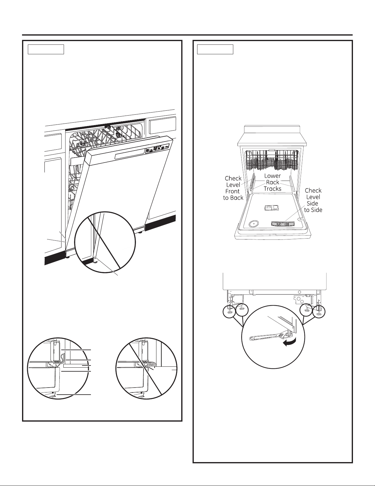
IMPORTANT – Dishwasher must be level for proper
dish rack operation, wash performance and door
operation. The dishwasher must be leveled left to right
and front to back. This ensures the dish racks will not
roll in or out on their own, circulation water will flow to
the pump inlet, and the door will close without hitting
the side of the tub.
• Remove the lower dish rack and place a level on the
door and lower rack track as shown in figure.
Door
Fits and
Swings
Back
Behind
Cabinet
Frame
Correct
Alignment
•
Adjust the level of the dishwasher by individually
turning the 4 legs on the bottom of the dishwasher as
shown. Ensure all 4 legs are firmly in contact with the
floor.
Incorrect Alignment
will result in door damage
Door Catches
on Cabinet Frame
Tip: Prevent unnecessary service charges for
panel damage or wash performance.
Make sure utility lines are not trapped or crushed behind
dishwasher. Crushed lines will restrict water flow.
Check that tub trim does not
contact the door at all points
Do not allow tub trim to get
trapped by or come into
contact with the door
LEVEL DISHWASHER
Top
View
Tub trim may be trimmed if
necessary to ensure proper
door operation
Tub frame
Tub trim
Cabinet
Door
Handle
Top
View
Tub trim
trapped
by door!
Turn Legs
to Adjust
• The dishwasher is properly leveled when the level
indicator is centered left to right and front to back.
Also, the dishwasher door should close without hitting
the side of the tub.
• Replace the lower rack.
Tip: Prevent unnecessary service charges. Verify
dishwasher is leveled.
Pull the dish racks half way out. They should stay put.
Open and close the door. The door should fit in the
tub opening without hitting the side of the tub. If the
racks roll on their own, or the door hits the side of tub,
re-level the dishwasher.
10
 Loading...