

Page 1
GE Appliances
Installation Instructions
Dry Enhancement Kit
WD35X10394
February 2013
Dishwasher Dry Performance
Verify proper heater operation, check for error
codes in diagnostic error mode, including
thermistor and/or wash temperature error codes.
Enter service mode to test heater operation. Full
directions to enter diagnostic and service mode
can be found in service guide 31-9226 or the
dishwasher's mini-manual.
If none of the above issues apply, follow all steps
in these instructions.
Models:
GDF510P DO
Parts Included:
This kit includes all parts needed for the above
model.
° Main control board WD21X10530
° Vent cover
° Foam strip (black in color)
° Door harness wire tie (may not be needed)
° Installation instructionsWD00X1019
Step I - Remove Power from the
Dishwasher
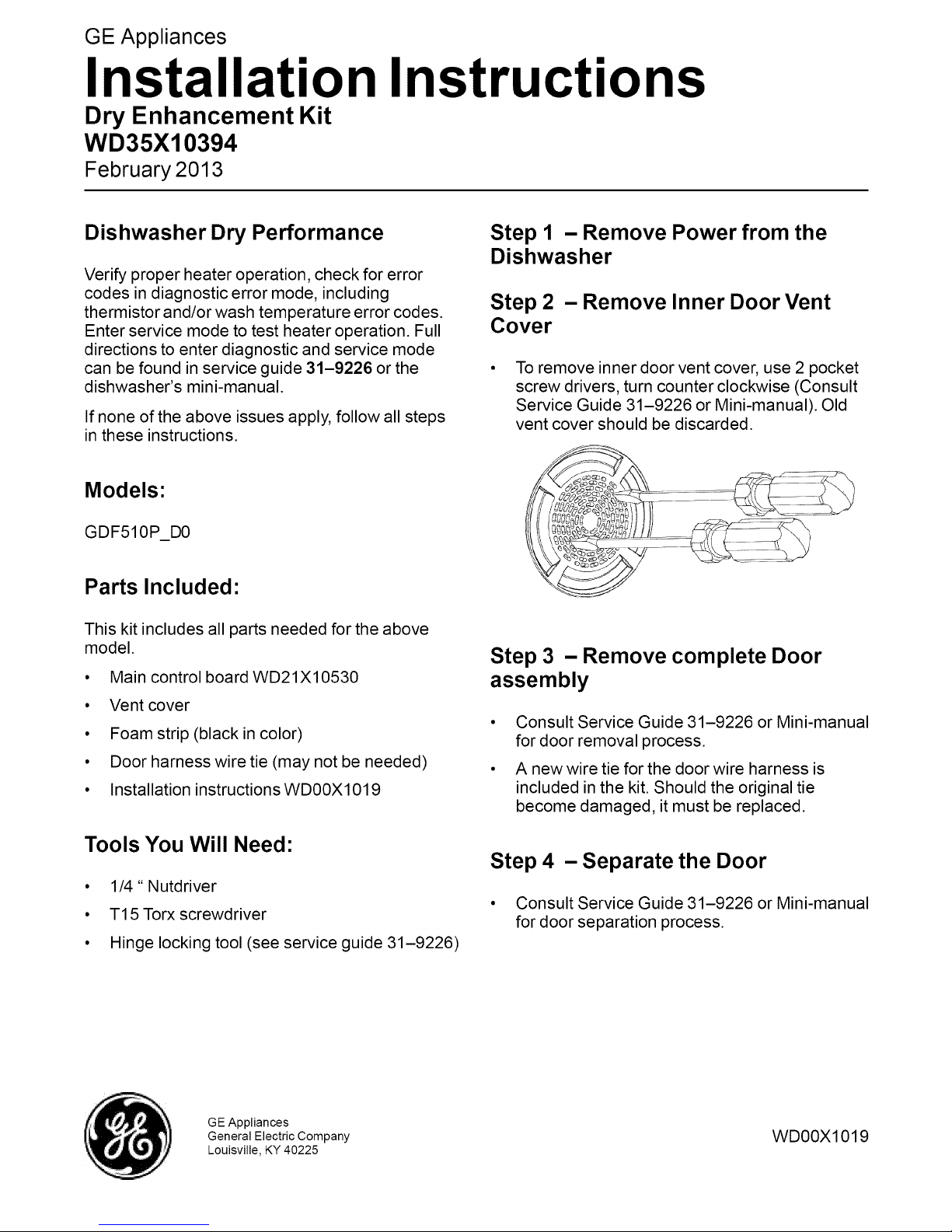
Step 2 - Remove Inner Door Vent
Cover
To remove inner door vent cover, use 2 pocket
screw drivers, turn counter clockwise (Consult
Service Guide 31-9226 or Mini-manual). Old
vent cover should be discarded.
Step 3 - Remove complete Door
assembly
° Consult Service Guide 31-9226 or Mini-manual
for door removal process.
° A new wire tie for the door wire harness is
included in the kit. Should the original tie
become damaged, it must be replaced.
Tools You Will Need:
• 1/4" Nutdriver
• T15Torx screwdriver
• Hinge locking tool (see service guide 31-9226)
GE Appliances
General Electric Company
Louisville, KY 40225
Step 4 - Separate the Door
° Consult Service Guide 31-9226 or Mini-manual
for door separation process.
WD00X1019
Page 2
Step 5 - Remove Front Control
Console
Step 9 - Re-assemble Inner to Outer
Door Panels
• Remove the front control console from the
inner door assembly, consult Service Guide
31-9226 or Mini-manual.
Step 6 - Remove Vent Conduit
• Remove the 2 - T15 Torx screws to remove the
vent conduit from the front console.
• Vent conduit can now be removed.
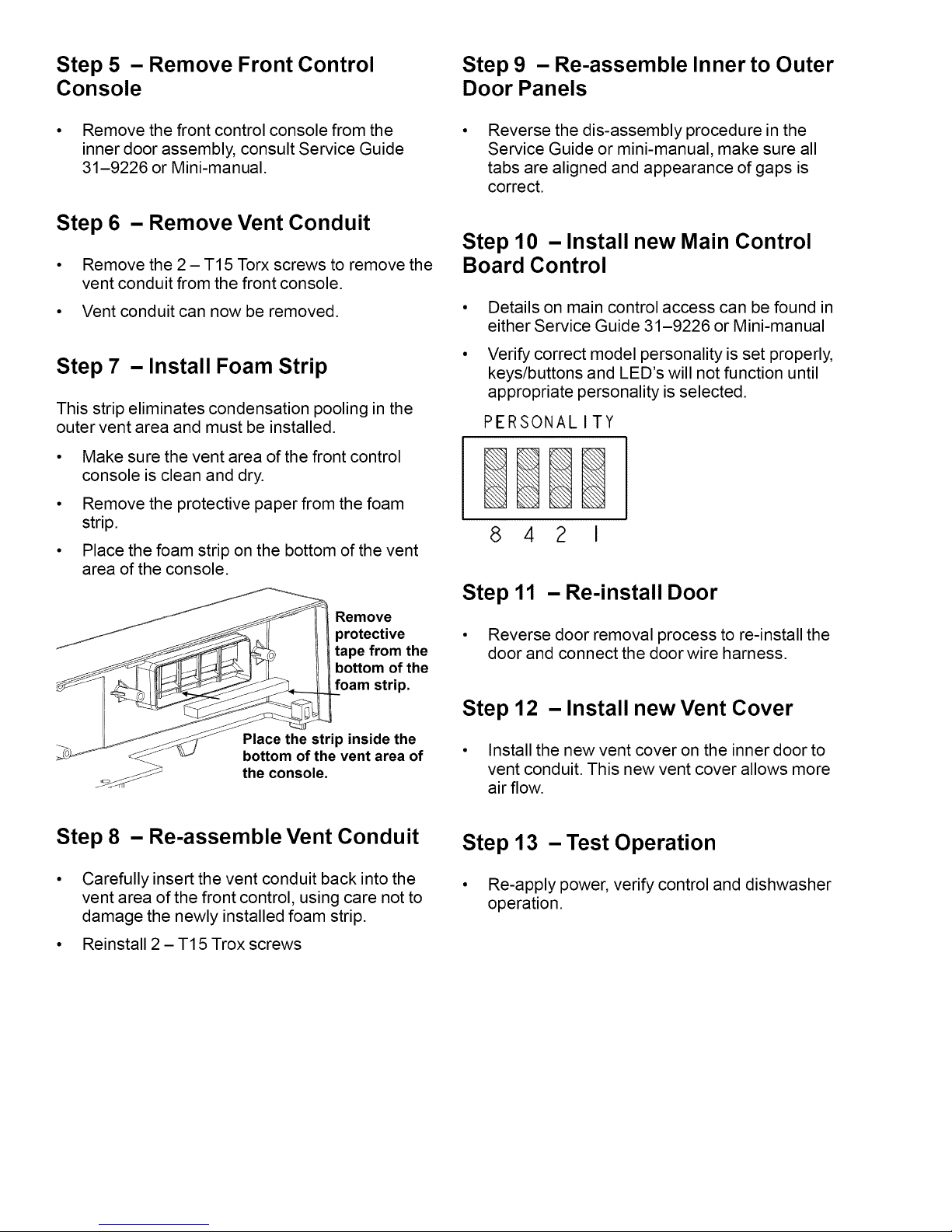
Step 7 -Install Foam Strip
This strip eliminates condensation pooling in the
outer vent area and must be installed.
• Make sure the vent area of the front control
console is clean and dry.
° Remove the protective paper from the foam
strip.
• Place the foam strip on the bottom of the vent
area of the console.
Reverse the dis-assembly procedure in the
Service Guide or mini-manual, make sure all
tabs are aligned and appearance of gaps is
correct.
Step 10 - Install new Main Control
Board Control
Details on main control access can be found in
either Service Guide 31-9226 or Mini-manual
Verify correct model personality is set properly,
keys/buttons and LED's will not function until
appropriate personality is selected.
PERSONALITY
842 I
Remove
protective
tape from the
bottom of the
foam strip.
Place the strip inside the
bottom of the vent area of
the console.
Step 8 - Re-assemble Vent Conduit
Carefully insert the vent conduit back into the
vent area of the front control, using care not to
damage the newly installed foam strip.
° Reinstall 2 - T15 Trox screws
Step 11 - Re-install Door
• Reverse door removal process to re-install the
door and connect the door wire harness.
Step 12 -Install new Vent Cover
• Install the new vent cover on the inner door to
vent conduit. This new vent cover allows more
air flow.
Step 13 - Test Operation
• Re-apply power, verify control and dishwasher
operation.
 Loading...