

Page 1
GE Consumer & Industrial
GE Appliances
General Electric Company
Louisville, Kentucky 40225
Service Bulletin
DISHWASHERS DD 04-04
SHORT DOOR ELECTRONIC DISHWASHERS
SENSOR MODELS: EDW3000G02, GSD5400G02,
GSD5500G02, GD5800G02, GSD5900G02
AND LATER
NON-SENSOR MODELS: GSD4800J01 AND LATER
SEPTEMBER 2004
NEW ELECTRONIC CONTROL
The short door electronic dishwashers feature a new electronic control that replaces the sequence switch and control
on previous models with a synchronous detergent trip motor
and a control with relays on the main circuit board.
There are two different controls–one for sensor models and
the other for non-sensor models.
The control for use on sensor models is a WD21X10197. This
looks similar to the control used on the Triton XL and stainless
steel line of dishwashers. However, the controls are not
interchangeable. The keypad is now a separate part, but
functions and looks the same as the keypad on the previous
integrated control. There are two keypads used: WD21X10198
and WD21X10199.
WD21X10197 WD21X10198 and
WD21X10199
The control used on the non-sensor models is a WD21X10195.
This control looks similar to the WD21X10100 used on the
previous non-sensor models.
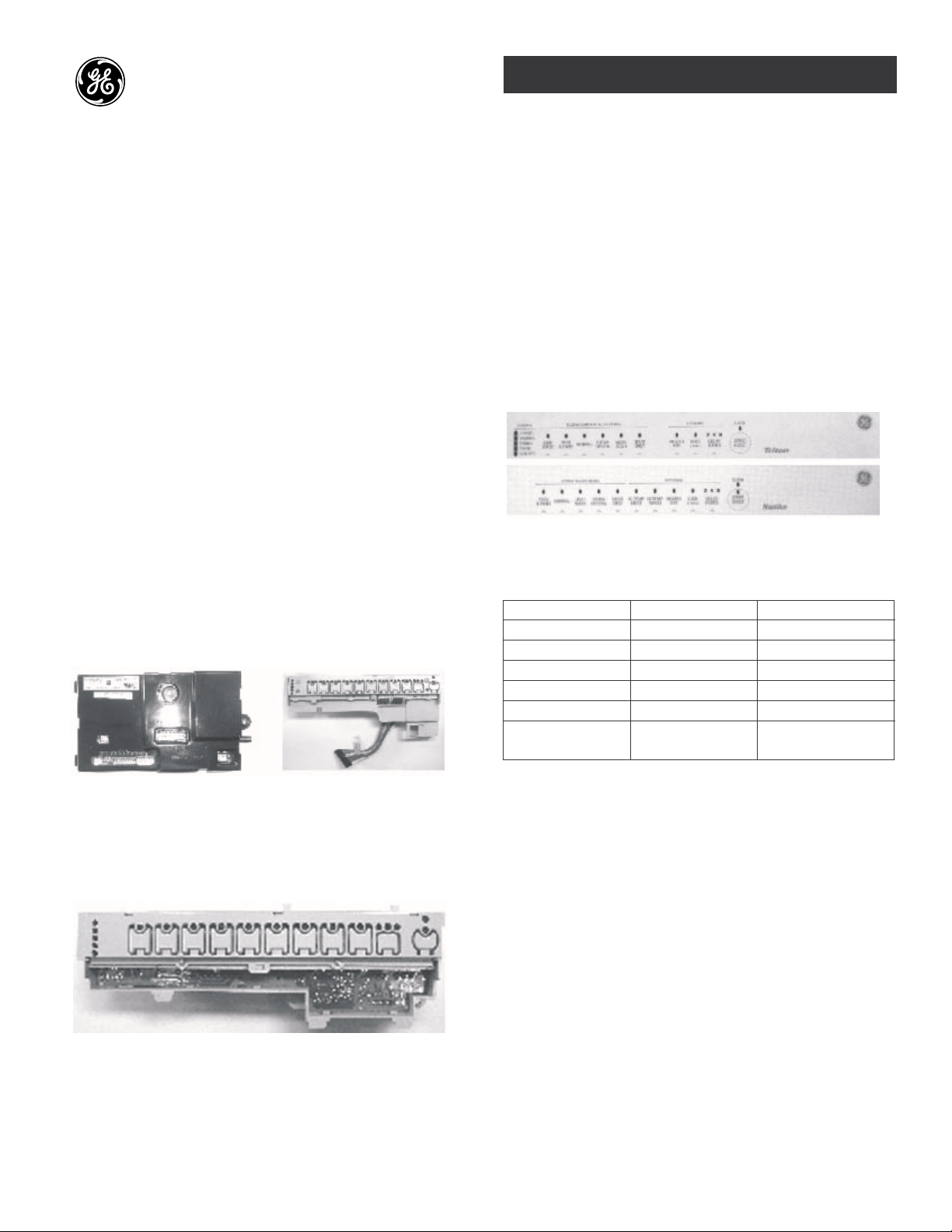
The look of the escutcheon and insert is unchanged.
Shown below is a table of features in the new controls.
Characteristic Sensor Control Non-Sensor Control
Detergent Trip Synchronous motor Synchronous motor
120 volt switching Relays Relays
Model Selector Keypad Resistor jumper plug
F1 Test cycle Normal & Pots Normal & Pots
Service mode Pads 9 & 3 Pads 9 & 1
Trip detergent cup if Feature not available Feature not available
inadvertently closed (manually open cup) (manually open cup)
Please note a service mode feature is now included in the
control. This functions much like the Service Mode on Triton
XL dishwashers. Pertinent sections of the respective minimanuals are attached to this Bulletin for reference.
Also note that previous short door electronic models had a
feature that allowed customers to open the detergent cup by
pressing the start pad three times with the door unlatched.
This feature is not available on the new controls. The Owner’s
Manual mentions the availability of this feature on page 14 or
13 respectively. Be aware this is incorrect. The Owner’s
Manuals have been corrected.
WD21X10195
Early production sensor models do not flash the washing light
or any other light on reset. The Owner’s Manual says the
washing light should flash on reset. The programming in the
control will be modified to include this feature beginning with
September 2004 production. A reset on non-sensor models
will cause the Start/Reset light to flash for 90 seconds.
GE CONFIDENTIAL AND PROPRIETARY INFORMATION–NOT FOR PUBLIC DISCLOSURE
ND 9210404
Page 2

Listed below are the control error codes the customer could see or hear
and possible fixes:
Sensor Models
Flashing Light Explanation Possible Cause
No light with
continuous beeping
sound
Normal light with
beeping sound
Note: No lights flash when cycle is cancelled and the dishwasher is resetting.
Non-sensor models
Flashing Light Explanation Possible Cause
Start/Reset
Normal light with
beeping sound
Key pad not plugged in or model
typing resistor on keypad circuit
board not detected
Normal light flashes and control
beeps when the detergent trip motor
cannot find its home position
Cycle cancelled, dishwasher resetting
Normal light flashes when the
detergent trip motor cannot find its
home position
Check and repair or replace the following as required:
1. Keypad plugged in
2. Keypad
3. Control
Check and repair or replace the following as required:
1. Connections to detergent trip motor
2. Operation of trip motor sensing switch
3. Operation of trip motor
4. Cam and detergent trip mechanism for free operation
5. Control
Normal operation
Check and repair or replace the following as required:
1. Connections to detergent trip motor
2. Operation of motor sensing switch
3. Operation of trip motor
4. Cam and detergent trip mechanism for free operation
5. Control
Clean light with
beeping sound
Listed below are control error codes visible only during the F1 test and only on sensor models.
Flashing Light Explanation Possible Cause
Sensing light and
continuous beep
Heated dry light
Lock light EEPROM error
Model typing plug not detected
Control is receiving an unexpected
signal from the turbidity sensor
Control is reading the tub
temperature sensor as open or short
circuit (thermistor is in the turbidity
sensor)
Check and repair or replace the following as required:
1. Jumper resistor – correct and properly plugged in
2. Control
Check and repair or replace the following as required:
1. Turbidity sensor connections
2. Turbidity sensor
3. Control
Check and repair or replace the following as required:
1. Turbidity sensor connections
2. Turbidity sensor
3. Control
Check and repair or replace the following as required:
1. Control
Page 3

165D6290G028
MODELS WITH A TURBIDITY SENSOR
1098765 3421
NOTE: INDICATES KEYPAD USED ONLY ON
SOME MODELS.
TO ENTER F-1 TEST CYCLE:
1. Power up unit.
2. Close detergent cup and latch door.
3. Press KEYPAD #9 and KEYPAD #8 simultaneously for
one second. The control will then step through the test
automatically.
TO EXIT F-1 TEST CYCLE:
1. Press START/RESET to skip each step until the end.
2. The control will then exit the test cycle, pump out any
remaining water and return to normal operation.
THIS DISHWASHER IS PROGRAMMED WITH A SERVICE
MODE TO AID THE TECHNICIAN IN TROUBLESHOOTING
THE DISHWASHER. EACH COMPONENT MAY BE CYCLED
TO DETECT IF IT IS FUNCTIONING CORRECTLY. COMPONENTS ARE CYCLED BY PRESSING KEYPADS TO THE LEFT
OF THE START/RESET KEYPAD. USE THE MATRIX BELOW
TO DETERMINE HOW TO CYCLE EACH COMPONENT.
TO ENTER SERVICE MODE :
PRESS KEYPAD #9 AND KEYPAD #3 SIMULTANEOUSLY FOR 3
SECONDS.
TO EXIT SERVICE MODE :
PRESS THE START/RESET KEYPAD AT ANYTIME TO EXIT.
Service Mode Test Matrix*
Keypad Description Time in Seconds**
9 Activates Water Valve 50
8 Activates Heating Element 600
7 Activates Main Pump 75
6 Activates Detergent Module 60
5 Activates Drain Pump 75
3 Activates the following in order: 3 seconds each cycle
Status LEDs; Wash LEDs;
Start/Reset and Option LEDs
2 Opens Active Vent
1 Closes Active Vent
START/RESET Used to EXIT Service Mode
*NOTE: After 15 minutes of inactivity, the service mode will
automatically turn off.
**NOTE: Component will be activated for indicated time.
Component may be deactivated by pressing the same keypad
that was pressed to activate the component.
F-1 TEST CYCLE MATRIX
STEP ACTION LED DISPLAY DESCRIPTION
1 Start
2 Model Number Display
3 Illuminate Display All LED’s Energize all LEDs for 5 seconds.
4 Trip Detergent & Fill DRYING, SANITIZED
5 Fill & Circulate RINSING
6 Circulate & Heat RINSING, SANITIZED
7 Calibration SENSING
8 Circulate & Drain RINSING, DRYING
9 Circulate RINSING, DRYING, SANITIZED
10 Trip Rinse Agent & WASHING
Self diagnostics
11 Fill WASHING, SANITIZED
12 Fill & Circulate WASHING, DRYING
13 Circulate & Heat WASHING, DRYING, SANITIZED
14 Auxiliary Pump All LED’s
15 Auxiliary Pump WASHING, RINSING,
16 Exit
NOTE: DELAY START 1, 2 & 3 represent the
LEDs, respectively.
In STEP 10 of the F1 Test Cycle: If the control senses a turbidity sensor error, the control
will flash the SENSING LED. If the control senses a tub temperature sensor error, then the
control will flash the HEATED DRY LED. If the control senses an EEPROM error, then the
control will flash the LOCK LED.
will not advance to STEP 11 until a key is pressed.
SENSING and WASHING flash
for 10 seconds
Combination of KEY 1 (LOCK)
and DELAY START 1, 2 or 3
SANITIZED
leftmost, middle and rightmost
If any of these diagnostic errors are detected, the cycle
Use KEY 1 (MS3) and DELAY
START LEDs to display model
number in binary for 5 seconds
Trip the detergent cup. Energize
the water valve for 50 seconds.
Energize the water valve and
main pump for 10 seconds.
Close the active vent.
Energize the main pump and
heater for 60 seconds.
All relays and LEDs will be off
while the processor calibrates
the turbidity sensor.
Energize the main pump and
auxiliary pump to evacuate water
from the unit for 10 seconds.
Energize the main pump to
circulate water in the unit for
50 seconds.
Trip the rinse agent. Read
Turbidity Sensor. Read tub
temperature sensor. Read
EEPROM. If diagnostics or turbidity
errors occur, energize the beeper
and flash LEDs (see below).
Energize the water valve for 50
seconds.
Energize the water valve and main
pump for 3 seconds.
Energize the main pump and
heater for 60 minutes.
Energize all LEDs and the auxiliary
pump to evacuate water for 5
seconds. Open the active vent.
Energize the auxiliary pump to
evacuate water from the unit for
70 seconds.
DELAY START
Page 4

165D6290G029
MODELS WITHOUT A TURBIDITY SENSOR
THIS DISHWASHER IS PROGRAMMED WITH A SERVICE MODE TO AID THE TECHNICIAN IN TROUBLESHOOTING THE DISHWASHER.
EACH COMPONENT MAY BE CYCLED TO DETECT IF IT IS FUNCTIONING CORRECTLY. COMPONENTS ARE CYCLED BY PRESSING
KEYPADS TO THE LEFT OF THE START/RESET KEYPAD. USE THE MATRIX BELOW TO DETERMINE HOW TO CYCLE EACH COMPONENT.
1098765 3421
NOTE: INDICATES KEYPAD USED ONLY ON SOME MODELS. WHILE THIS KEYPAD MAY
NOT BE VISIBLE, THE INDICATED SPACE SHOULD ALWAYS BE USED AS A KEYPAD.
TO ENTER SERVICE MODE :
PRESS KEYPAD #9 AND KEYPAD #1 SIMULTANEOUSLY FOR
5 SECONDS.
Service Mode Test Matrix*
Keypad Description Time in Seconds**
10 Activates Main Pump 120
9
Activates Auxiliary Pump 60
Activates Drain Solenoid 6
8 Activates Detergent Module 30
7 Activates Water Valve 60
6 Activates Heating Element 120
START/RESET Used to EXIT Service Mode
TO EXIT SERVICE MODE :
PRESS THE START/RESET KEYPAD AT ANYTIME TO EXIT.
*NOTE: After 5 minutes of
inactivity, the service mode
will automatically turn off.
**NOTE: When a component
is activated in the SERVICE
MODE, the output will
continue to remain active
(ON) until the Maximum
time has expired or another
keypad is pressed.
N.D. 921-04
 Loading...