

Page 1
SEARS
3EPT.731A
TECHNICAL
FLASH
DISTRICT
MANAGER
CENTRAL
MANAGER
BRANCH
MANAGER
CALL
CENTRE
MANAGER
PARTS
MANAGER
T.
F.
46-106
JUNE
2OO4
CLAUDE
BABINEAU_
DEPARTMENT
73IA
DIVISION
46
SOURCE
C978
ERVICE
MANUA
DIVISION
46
G.E.
REFRIGERATORS
2OO3
ELBCTRONIC
BOTTOM-MOUNT
Page 2
GE
Consumer
& lndustrial
TECHNICAL
SERVICE
GUIDE
2003
Electron
ic
Bottom-Mou nt
Refrigerators
MODEL
SERIES:
GBS22_
_P
GBS20__P
PDS22__P
PDS2O
P
-=:
PUB # 31-9112
1tM
Page 3
IMPORTANT
SAFETY
NOTICE
The information
in this service
guide
is intended
for
use by
individuals
possessing
adequate backgrounds
of electrical,
electronic, and
mechanical
experience. Any attempt
to repair a
major appliance may
result
in
personal
injury
and
property
damage.
The manufacturer
or
seller cannot
be responsible
for the
interpretation
of this information,
nor can
it
assume
any
liability in
connection
with ib
use.
WARNING
To
avoid
personal
injury
disconnect
polver
before seMcing
this
product.
lf
elestrical
power
is required
for
diagnosis
or test
purposes,
disconnect the
power
immediately
after
performing
the
necessary
checks.
RECONNECT ALL GROUNDING DEVICES
lf
grounding
wires, screws,
Sfraps,
clips, nuts, or
washers used
to complete a
path
to
ground
are removed
for service, they must
be retumed
totheiroriginal
position
and
prcperlyfastened.
GE Consumer &
lndustial
TechnialServloe
Guide
Copynght@2004
All rights
reserved.
This
service
gufule
may not be reproduced
in whole
or
in
part
in
any
form without
written
permission
fiorn tte
Genenal Elecfic Comparry.
-2-
Page 4
Table
of
Contents
-3-
Page 5
Doors
The swing direction of the fresh food
door
and
the
freezer
door can be reversed
on
all
models
except
stainless steel.
Stainless steel models must
be ordered
as
left
or
right
door swing.
Removal
and
Replacement
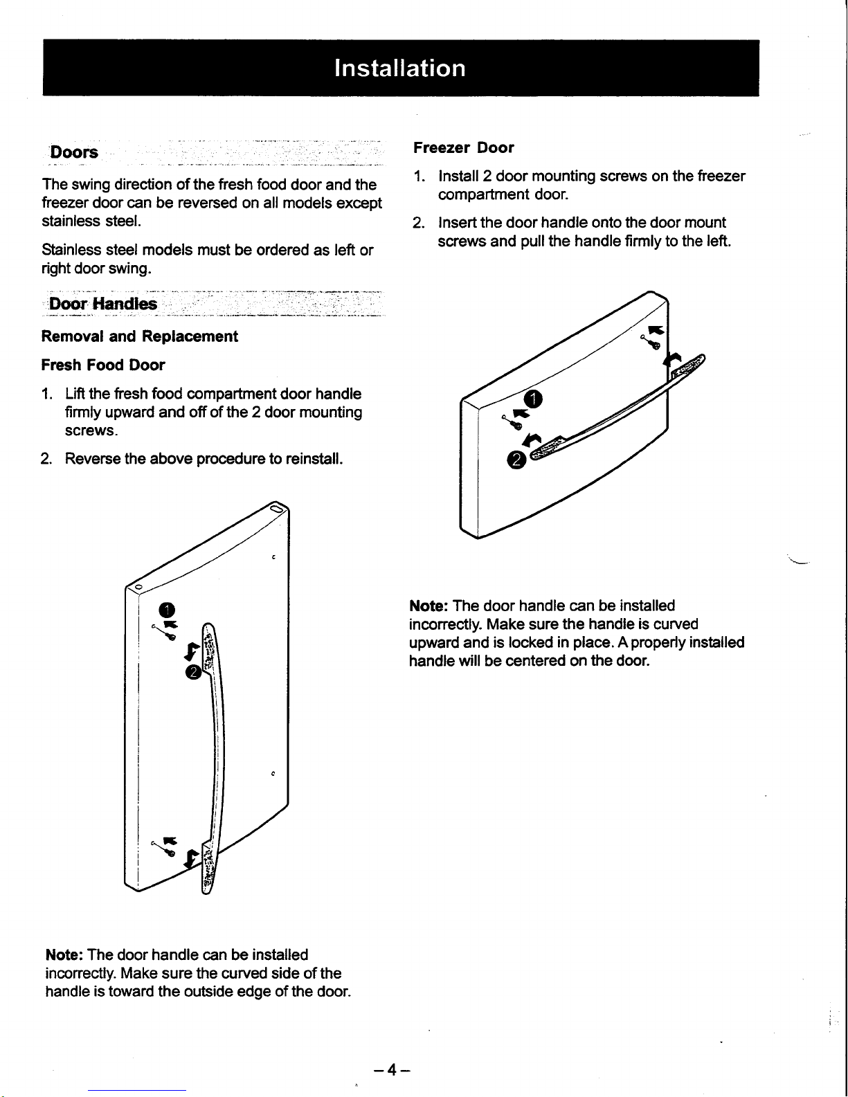
Fresh Food Door
1. Lifi
the
tresh food compartment
door handle
firmly
upward and
off
of the 2door mounting
screws.
2. Reverse the above
procedure
to reinstiall.
Note: The door handle can be
installed
inconectly.
Make
sure the curved side of
the
handle
is
toward the outside edge of the door.
Freezer Door
1. Install 2 door mounting screws on the
treezer
compartment
door.
2.
lnsert the door handle onto the door mount
screws and
pullthe
handle firmly to the
left.
Note: The door
handle can be installed
inconectly.
Make
sure
the
handle is
curved
upward
and is
locked in
place. A properly
installed
handle will be centered on
the
door.
-4-
Page 6
Troubleshooting
Tips - Handle Installation
Handle too hard b
instrlUHandle tequircs
excesive torce to
itlr;fg, l
Mormting
bolts too tight- Remove
the handle.
Loosen the mounting
bola
sltghtly so that the handle will
snap
into place
when installed.
Defective normting bracket
or
bolts.
Remove
handle.
Check for defective
mounting
brackets or bols. If defective, replace.
Install
handle according to Installation
Instructions.
Larce handle/l{andle
rmkes
ratiling noise
at
fficlnretrt
Loose
normtingbolts
If the
handle installs properly
(slides
on and
locks/snaps into place)
but
is
loose, remove the
handle and tighten the mounting
bola. Use
a
lomm
socket
and ratchet
or wrench. Do not use a
screwdriver as
it will
not provide
enough torque
for
proper tightening.
Reinstall handle
according
to Insrallation Instructions included wi&
the
handle.
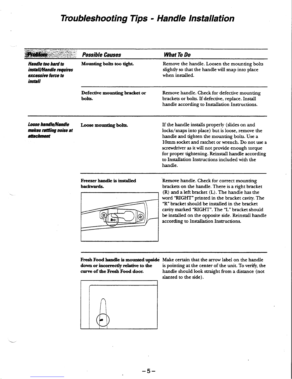
Freezer
handle is installed
baclmtards.
Remove handle.
Check for correct mounting
brackets
on
the
handle. There is
a right bracket
(R)
and a left bracket
(L).
The
handle has the
word
'RIGHT"
printed
in the bracket
cavity.
The
"R'bracket
should
be
installed in
the bracket
cavity marked
"RIGI{T".
The
"L"
bracket should
be
insr^lled on the
opposite side. Reinstall handle
according
to
Installation Instructions.
Fresh Foodhandle is mormtedupside
dorrn
or
incorrectly
relative to the
curve
ofthe Fresh Food door.
Make certain that the arrow label
on the
handle
is pointing at the center
of
the
unit. To
veri$,
the
handle should
look
straight from a
distance
(not
slanted to the side).
-5-
Page 7

ELECTRICAL
SPECIFICATIONS
Temperature
Control
(Position
5)...............
........32 - 4"F
Detrost Conhol...
60 hrs @ 40
mins with
no dooropening
OvertemperatureThermostat.............
140-110"F
Defrost Thermistor..
..--..-....70'F
Electrical Rating: 115V.
AC,
60 H2.................1
-
5Amp.
Maximum
Cunent Leakage.....
........0.5
mA
Maximum
Ground Path Resistan@...............0.
14 Ohms
Energy Consumption.......507
k\rVh/yr for
20
culft
models
Energy Consumption.......520
kWh/yr for
22 cuftmodels
NO LOADPERFORITIANCE
Control
Position:5€
And Ambient
of;..........
.....
90'F
Fresh
Food,
"F.....
.---...32
-
42
Frozen Food,
"F.....
.......
-5 -
5
Percent
Running Time...........
.........
45
-
65
REFRIGERANONSYSTETTI
Minimum
Compressor Gapacity Vacuum......
........
22 in.
Minimum
Equalized Pressure
@
70"F
38
PS|G
@
90"F......
49 PStc
Reftigerant- R- 134a..
4.06o2-
Compressor................
690 BTU/hr
INSTALLANON
Clearance
must
be
provided
at top, sides
and rear
of the
refrigerator
for
air circulation.
ATTOP......
.1
inch
AT SIDES..
0.125
inch
AT REAR...
1
inch
The evaporatorfan forces air through
the
evaporator
into the fteezer
compartment.
Air from the
evaporator
is
also
forced through
the
electronic damper to
the top
of the
air
tunnel,
through the fresh food compartment, and retums
to the evaporator.
The fresh
food
compartment
receives
chilled
air
through an electronic damper at the bottom, rear
of the
ftesh
food compartment. The damper is
controlled by the
main
control board. When
open,
the damper allows
chilled
air
ftom
the
freezer
to
move
into
the
fresh
food compartment.
Air retums
from
the ftesh
food
compartment
to the
freezer compartment
via two vents located
to the
left
and
right
of
the
airtunnel.
r
coLD
AtR
*=
MIXED AIR
r r r
flfl REIURN TO
EVAPOMTOR
\
1
.-&
\
FRESH
FOOD'
\.
\
i-$
-
FREEZER
t
,
!>
AIR FLOW
-6-
Page 8
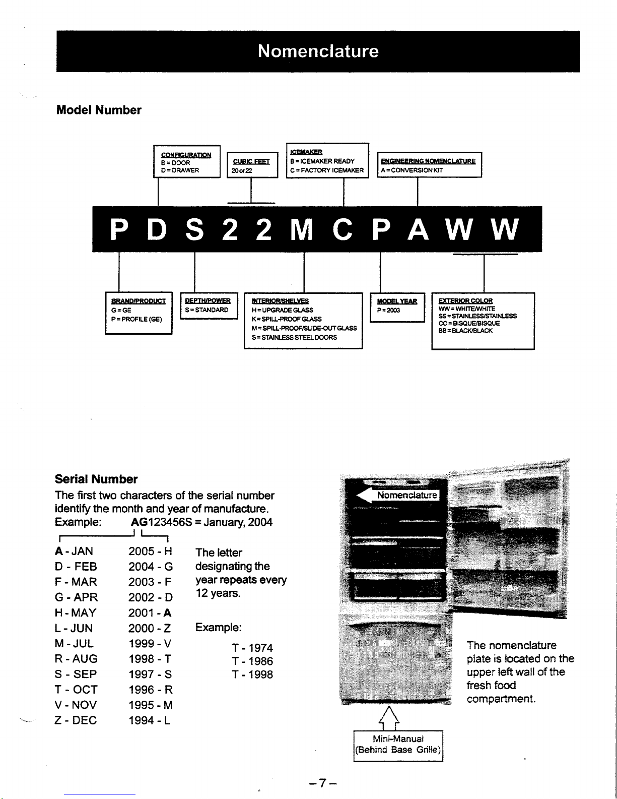
Model Number
V-NOV
Z-DEC
L.
JUN
M.JUL
1999 - V
R.
AUG 1998 - T
s-sEP
1997-S
T-OCT
1996-R
2O0O
-Z
ExamPle:
Serial Number
The first
two characters of the serial number
identify the month
and
year
of
manufacture.
Example: AG123456S = January 2004
A. JAN
2005-H
Theletter
D
-
FEB
2004
-
G
designating the
F - MAR
2003
-
F
year
repeats
every
G - ApR
2OO2
_D
1?years.
H
-
MAY 2OO1
-A
T - 1974
T - 1986
T - 1998
The nomenclaftlre
plate
is located on the
upper left wall
of
the
fresh
food
connpartment.
1995
-
M
1994 - L
i{TERICIR'SHELIGS
H=UPGMDEGT
SS
K=SPI!+ROOFG|.ASS
M
=
SPILIL'rPf{OOF/SUDEOUT
GLASS
S
=
STAINIESS STEEL DOORS
EITERbRCOLOR
WW= WHTTE/VI/HITE
Ss = SrANLESS,SfAINLESS
CC = BISOUE/BISOUE
BB=BLACKtsl-ACK
-7-
Page 9
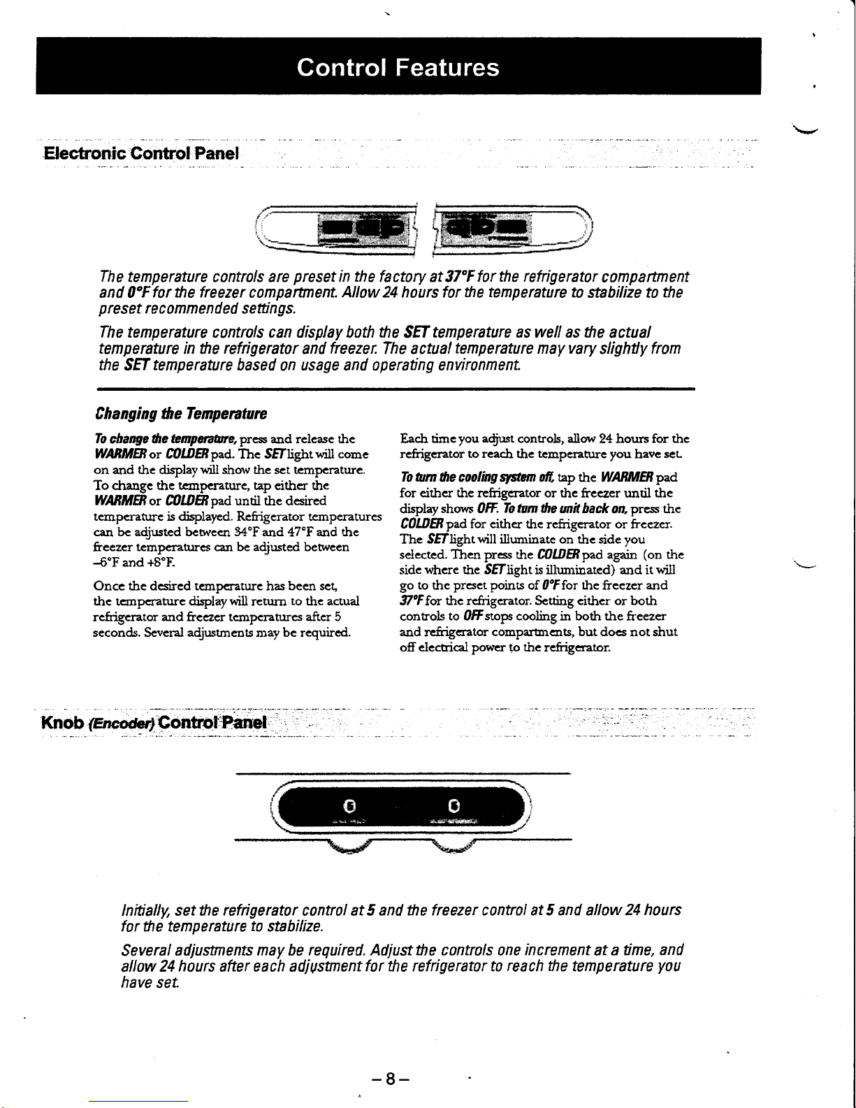
H ectronic Gontrol Panel
The tenperature controls are
preset
in
the
factory at 37"F
for the refrigerator
clmpartment
and OoF
for the freezer
compartnenL
Allow 24
hours
for the
temperature
ta
stahilize t0
the
p
res
et
re
c om
me n d
ed setti
n
gs.
The temperature
controls
can display both he
SEf
tenperature as well as the
actual
temperature
in the
refrigerator
and
freezer.
The actual
tenperature
nay vary
slighfly fron
the
SEf rcnperature based
0n
usage and operating envirlnment
C h a
ng i ng the Tempe
nta
re
To
change
the Eflrpqaane,press and
rclcase
thc
WBMBoT fiOl0Bpad. Thc SEf[ghtwill
come
on and the
displaywill
show the set tcmpcrature.
To drange the tcanperature, tap eithcr the
WAfrMBor C0lD8paduntjl the desired
temperahJre
is
displayed. Rcfrigerator temperatures
c:n be a{usted bcmeen 34'F
and 47'F
and
the
frcczcr
temperahrres can be adjusted betwccn
4"Fand
+8'F.
Once the dcsircd temperaturc has been set,
the tcrnpcrature
display wiil
r€turn
to
the actual
refrigerator
and
freezer tcmpcratures
after 5
seconds. Scveral adjr:stmens
nray
be required.
Each
timeyou
adjrrst
controls, allow
24 hours
for thc
rcfrigerator
to reach the tempcrahrrc you
have
seu
To
turn 6e cooling
qrsi/et,
fr,
ttp the
WABMB
pad
for either the refrigerator or the
freezer until
the
display
shom Otr.
To tum ,he
mit hack
on,
press the
C0UBpad
for either
the refrigerator or frcczcr.
Thc
Sff[ghtwill illuminate on the side
you
selectcd. Tlren press
the
C0o.ffipad again
(on
the
sidc
vihere the
SEllight is illnnrinated) and it
will
go to thc
prcsct poins
of OoFfor the
freezer
and
illoF
for
thc refrigerator. Setting cithcr or both
controls
to OfFstops cooling in both the
fi'eezer
and
rcfrigcrator
comparbrcns, but docs
not
shut
offdeccicai
power
to thc refrigerator.
Knob
(mcwlGontrol'Panel
lnitially, setthe
refrigerator
contrll
at 5 and
the freezer czntrol at 5 and
allow
24
hours
for the temperature
to
stabilize.
Several
adjustnents nay be
required. Adjustthe contrlls one
increment
at
a time,
and
allow
24 hours after each
adjUstnentfor
the refrigerat1r to
reach the
temperature
yTu
have
set.
-8-
Page 10
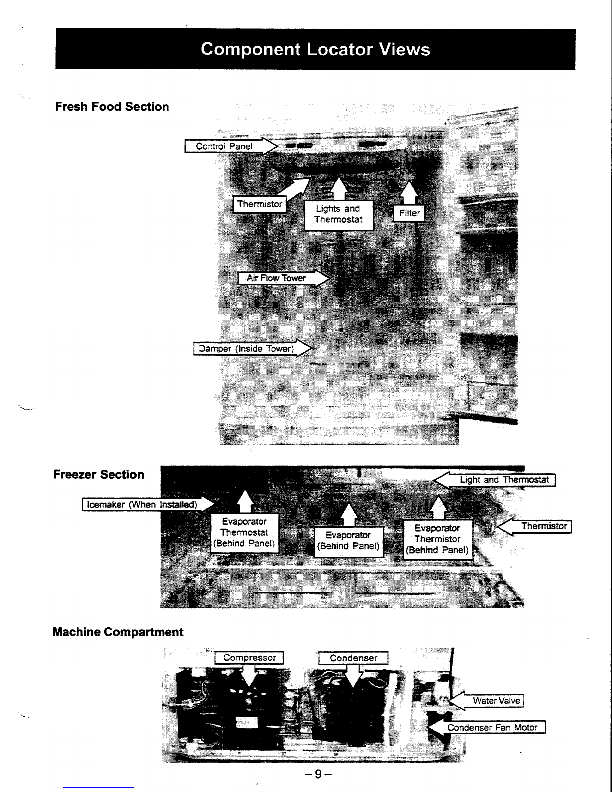
Fresh Food
Section
Machine
Gompartment
#
#
s,
i:is
#,
-9-
Page 11

Knob
(Encoder)
"
.
Electronic
and
mechanical
control
panels
are
removed in
the same manner.
Removal and Replacement
1. Remove
the fresh food light
cover.
2. Remove
the 2 screws that hold the rear
of the
control housing
to the liner ceiling.
3. There
are 3
posts
inserted into the liner
ceiling
holding
the front of the
control
in
place.
Firmly
pullthe
control housing down atthe ftont
edge
to release the
posts.
Pull the housing
towards
the front
to release the trabs in the
back.
Note: The foam
may be holding the
posts
and
tabs in the liner.
4. Unplug
the fesh food
light
connector
from the
compartment ceiling.
The fresh food light housing is held in
place
by
4 tabs. Press the tabs
to remove
the housing.
Unplug
the connectorfrom the control board.
Press
the
tab
on the
door
switch
and
push
the
switch through the
hole in
the control
panel
housing.
6.
7.
-
10-
Page 12

Air Flow
Tower
and
Damper:
'
The
air
flow
tower
contains
an intemal
damper.
The
damper
and tower
are replaced
as one
unit.
Removal
and
Replacement
1. Remove
the
2 screws
on the top
and bottom
of
the center
shelf bracket.
Remove
the bracket.
2.
Remove the
screw
from
the
bottom of the
air
flow
tower.
Lean the tower forward
to access
the
connector
at the bottom
of the tower.
Water Filter
On
ice
maker models, the water
filter is located
in
the upper, right
comer of the fresh food
compartment. The water
filter should
be changed
every 6 months.
To
access
the water filter,
press
the tab on
the
front
of
the water filter
cover
and allow the cover
to
drop
down.
Water
Filter
Part
# GSWF
3.
Unplug the connector;
then
remove the
airflow
tower.
Turn the water
filter counterclockwise
to
remove
and clockwise to
install.
Remove Install
Note: lf a new filter
is not
available, a filter bypass
must be
installed
to
supply unfiltered water
to the
icemaker.
Filter bypass
part
# WR02X11613
-11-
Page 13

.lcemaker
Ready
Models
The
accessory icemaker
can be
purchased
through
parts, parl#
lM6 or
as a sales accessory
part#
lM4Athrough
a dealer. The icemaker
must
be
installed
with
the filltube shipped with
the
refrigerator.
The
slot in the filltube must
be
on
top
of the tube.
The water fill
tube is
packaged
with
the use
and
care
manual
in
a
plastic
bag
in
the vegetable
drawer.
The
fill tube
part
number is WR02X11712.
-,fr9sn
Food
and Freezer Thermistors
Thermistor
Values
Temperature
Degrees
(F)
Resislance in
KiloOhms
Temperature
Degrees
(C)
-40
166.8 kO
-40
-31
120.5 kO
-35
-22
88 kO
-30
-13
65
kO
-25
4
48.4 kO
-20
5
36.4 K)
-15
14
27.6 kO
-10
23 21 U,O
-5
32 16.3 ko 0
41
12.7 t&
5
50 10 ko
10
59 7.8
kO 15
68 6.2 kO
20
T7
5ko 25
86
4ko
30
95 3.2
kO
35
1U
2.6
kO
40
113 2.2ko, 45
122 1.8
kO
50
55
1.5 kO 40
60 1.2k4
-35
The fresh food thermistor
is located
on the
ceiling
of
the fresh food compartment behind the light
assembly.
-
The freezer thermistor
is located
on
the rear
of the
right hand wall in the freezer section.
Note:
Fresh food
and
freezer thermistors are
removed
in the same manner.
To remove
the thermistor cover,
insert a flat
blade
screwdriver
under the
front of the cover
and
genfly
lift
the cover. Squeeze and
lift the cover from the
boftom until
it releases from the compartment wall.
-
12-
Page 14

Note:
Some of the foam insulation
may need
to
be
removed
to expose
the thermistor
and
wire.
i{.
Thernristor
When replacing
the thermistor,
cut the thermistor
wires
and splice the new
thermistor
using bell
connectors
as shown.
Always
use
RTV102
silicone sealant to seal the
end of the
connector
from moisture.
Note:
The
thermistor must
be
inside
the
thermistor
cover but is not required
to
be
inserted
back
into
the insulation
or
inside
the
cabinet frame.
Evaporator Fan
The
evaporator fan is located
above the
evaporator
behind the
rear
panel
of the
treezer
compartment.
The
evaporator
fan
is held in
place
by 2 screws.
To
access the fan, remove
the
drawers, shelves,
and
icemaker
(if
installed)
from the freezer
compartment. Remove the
back
panel.
The fan, motor,
and
mount
come out
as one unit.
Shown with
Back
Panel
Removed
Evaporator Thermistor
The evaporator
thermistor
is located
on top of the
evaporator behind the rear
panel
of the
lreezer
compartment. The thermistor is held
in
place
by
a
tie strap.
To
access the thermistor, remove the
drawers,
shelves, and icemaker
(if
installed) from
the
lreezer
compartment.
Remove
the back
panel.
Shown
with Back
Panel Removed
When replacing
the thermistor, cut the thermistor
wires
and splice the
new
thermistor using bell
connectors
as shown.
Always
use
RTV102
silicone sealant to seal the end of the connector
from moisture.
Use
a new tie
strap to secure
the
thermistor to the evaporator tubing.
ti"=.1
t
":,
":
i#.,
':
.
:,:
r". ..,'-
.
t'^
-13-
Page 15

Evaporator
Thermostat
The
defrost
heater is controlled
by the
evaporator
thermistor
and normally
tums offat
70'F. lf
the
evaporator
thermistor
fails,
the evaporator
thermostat
will
turn off
the defrost
heater
at 140"F
and will
reset
at 110"F.
The
evaporator
thermostat
is
located
on the
top,
left
side of the
evaporator
behind
the back
panel
of
the freezer
compartment.
To
access
the
thermostat,
remove
the
drawers,
shelves,
and
icemaker
(if
installed)
from
the
freezer
compartment.
Remove
the
back
panel.
Shownwith
Back
Panel Removed
The
thermostat is
held
in
place
by
a spring tab.
To
remove
it,
squeeze
the
tab.
Note:
The
resistance
of the
thermostat
and
defrost
heater
can be taken
by removing
the
access
panel
located in
the upper left
section
of the
evaporator
cover. Remove the
screw and
pullthe
cover
forward
to expose the two-wire
connector.
Unplug
the
connector
and
read
the resistance
between
the
two terminals.
Since the
thermostat
and heater
are
in
series, the reading
should be approximately
32 0.
When replacing
the
thermostat,
cut the thermostat
wires and
splice the new
thermostat
using bell
connectors
as shown. Always
use RTV102
silicone sealant to
seal the end
of the
connector
from moisture.
-14-
Page 16

Fresh
FoddAifti
Fresh
Food
LightThermostat
\*
The
fesh food
light
thermostat
intemlpts
power
to
the fresh
food
lights when
the
temperature
reaches
175"F.
Power
is
restored
when
the
thermostat
temperature
cools
to 155'F.
The
thermostat
is located
on the
back
of the
fresh
food
light
housing.
To
access
the
thermostiat,
remove
the
control
panel
(see
Control Panel).
The
thermostat
is held
in
place
by 2
screws.
:reezer
Light
Thermostat
The
freeze
r
fl ight
thermostat
i ntemr
pts
power
to
the freezer
lights
when
the
temperature
of
the
disk
reaches
175'F.
Power
is restored
when
the
thermostat
temperature
cools
to
155"F.
The
thermostat
is located
behind
the
freezer light
housing.
To
acoess
the
thermostat,
remove
the fteezer
light
cover
and housing.
The
housing
is
held in
place
by
5
screws.
Note: To
gain
better
access
to
the
thermostat,
pull
the
housing
down
untilthere
is enough
room
to
remove
the thermostat.
\ffhen
replacing
the thermostiat,
cut the thermostat
wires
and splice
the
new
thermostat
using bell
connectors
as shown. Always
use RTV102
silicone
sealant to
seal the
end of the
connector
from
moisture.
-15-
Page 17

Removal
and Replacement
1.
Open the freezer
drawer
until it
stops.
2. The bottom
basket
rests
on a frame
inside
the
lreezer
drawer.
To remove
it, liftthe
basket
ftom
the
back and
slide it toward
the
freezer
compartment.
3.
Remove
the single Phillips-head
screw on
each side
of
the
rail.
Note: Do not
remove
the
hex-head
screws from
the
rail
assemblies.
The
tabs on the side of
the drawer
rails
fit into
the front
slots of the
guide
rails.
Lift
the
drawer
by the handle to
separate the
drawer
rails
ftom
the
guide
rails.
Set
the
drawer
on a
non-scratching
surface.
Remove
the middle
basket, top
basket, ice
tray
shelf, dnd
ice
bin.
The
center rail
assembly is held
in
place
by
a
molded
channel in
the
treezer
ceiling and
notches in
the metal
support rails.
Remove
the
center rail assembly
by
pressing
down
on the
metal
support
rails while
rotating
the
bottom
edge of
the
center rail assembly.
To remove
the metal support rails,
press
the
tabs
on the
plastic
support housing.
Remove the 3 Phillips
screws that
hold
the
plastic
support housing
in
place.
5.
6.
7.
8.
4.
o
IXt
t{OTnmow
ter headccnua
Page 18

10. Pullthe
front
edge
of the
plastic
support
housing
away from
the
side wall. Pull
the
housing
forward
to
disengage
the rear
tabs.
Note:
The
plastic
housing
may
be tight
against
the
side wall,
and the tabs
may
be
foamed
in
place.
Some force
may
be
required
to remove
it.
11.
To remove
the
guide
rails
trom the
plastic
support housing,
lift
the
tab
on
the
back
side
of
the housing
with
a
smallflathead
screwdriver.
Freezer
Drawer Shim
lf
the
drawer is
not sealing
correctly
and the
gasket
is
not
damaged,
the
door alignment
can
be
adjusted.
Remove
the Phillips
screws holding
the rail
connector
to the
drawer front.
Using the necessary
number
of
stainless steel
washers,
shim the
drawer
to
provide
the
correct
alignment.
The
door
gaskets
are fttted tightly
into the door
channel.
They
should not
be removed
unless they
need
to
be replaced.
Note: When
replacing
a
gasket,
a wide
blade
screw
driver may
be necessary
to
remove
the
gasket.
-17-
Page 19

--'--'..T:--
-:''
-"
r.'-.:'
-:-
::..*.?
:"'-'
i
:-.'
::- ::;'i--i.a.'i-;l:.-
Gontr.ol
Diagnpstbs
_,
.,,
_-l_1,.-..--,.i;,',:ir..;:=.
A
diagnostic
aid
can
be assembled
which
consists
of a control
board,
membrane
and wiring
hamess.
The
parts
required
are WR55X10120,
WR55X1
0068
and
WX05X14999.
The
control
diagnostics
allow
the
technician
to
functionally
test individual
components
to
aid
in
troubleshooting.
On the electronic
bottom
mount
models,
the
diagnostics
are
performed
by removing
the
existing
temperature
control
board
and
plugging
in
the diagnostic
aid or by accessing
the main
board
on the back
of
the reftigeratorand
plugging
into
the
J4 connector.
Note: Refrigerators
with
an electronic
temperature
control must
have
the control
disconnected
before
attempting
the
diagnostics
test from
the main
controlboard.
1. Enter the
diagnostic mode
by
pressing
both
the feezer temperature
(cor-oen
and
wnnuen)
pads
and the
refrigerator
temperature
(cor-oen
and
wnnuen)
pads
simultaneously.
Note: All four
pads
must be held for
approximately
3 seconds.
Blinking
"0's"
in
both displays indicate
the refrigerator
has
entered the test mode.
3. Press
and release
any
pad
other
than
the
temperature
pads
to
active the test mode.
4. Enterthe
display numbers
as shown
in
the
diagnostics
chart on the next
page
for
the test
desired.
5. Press
and release
any
pad
otherthan the
temperature
pads
to
active the test mode.
Note: Selected models have limited
test
capability.
See
the COMMENTS
column in the Diagnostics
Chart
on the next
page
for
clarification.
-
18-
Page 20

FREEZER
DISPLAY
FRESH
FOOD
DISPI-AY
DIAGNOSTICS
RESULTS
COMMENTS
0
c
Encoder
Test
As
the knob is
rotated
the
d'splay will
show the
corresponding
setting
Only
for models
with
temperature
control knobs
0
7
Control
and
Sensor
System
Test
Checks
each
thermistor
and
displays
"P"
for
pass
and
"0"
for fail
See Note
1
below
for display
order
1
0
Dampers
Test
Opens
each damper,
pauses
briefly
and then
closes.
lncludes
Custom
Cool
dampers if
applicable
1
Fan Test
Runs
each fian
in
sequence
for 10
seconds
each.
1
2
100%
Run Time
Sealed
system
on
100%
ofthe
time.
Times out
after t hour.
1
3
Prechill
Test
Starts
Prechill
mode.
Unit
retums
to normal
on its
own.
,|
4
Defrost Test
Toggles
on the Defrost
cycle.
See
Note
2 below
Must
press
again to tum
heaters
off. See Note
2
1
5
Main
Confol Reset
Causes
a system reset
1
6
Exit Diagnostic
Mode
Causes a temperature
control board reset
1
7
Degrees
C'/Fo
Changes
ftom F'to
C' or C'
to
F"
on
temperature
display
See Note
3
belour
Note
1 .
#1
-
Single Fresh
Food
Thermistor
#3
-
Custom
Cool #4 - Evaporator
#5 - Freezer
Thermistortestresultsare:
P
=
Pass
0 = Fail
S
=
Shortto
5VDC B
=
Bad
amplifier(replace
main
control)
Note
2. You
must
enter
the
defrost test
again
to toggle
the defrost
heater
off
at the
end of the
test. The
heater
will
not
come
on if the
evaporator
thermistor
is
warm.
Note
3. Press
FF
temperatrire pad
(warmer/colder)
to
toggle.
Using the
service
test
board,
you
can
change
the
temperature
display
from Fahrenheit
to Centigrade
on the refrigerator
display,
but the
customer
will
be
unable to
change
it back
without
using
a service
test
board.
Refer
to Service
Guide
31-9072 for
additional information
Gondenser
Fan
Noise
Symptom:
Loud
airflow
noise
coming
from
the
condenser
fan
compartment.
Problem:
The
plenum
is
bent
out of
position
due
to
the screw
tab being
tightened
at an
angle.
Solution:
Release
the
tension
off the
plenum
by
loosening
the
screw
tab.
Straighten
the
plenum
to
the
proper
position
around the
fan
blade.
Tighten
the screw
so the
tab is
straight.
Photo
Shown
with
Plenum
in the
Bent Position
-19-
Page 21

Strip
Gircuits
3-Wre Electronic Temperature
Control
Damper
6-Wire
Encoder
Temperature Control
Thermistorc
Condenser and
Enaporator
Fan
MOTHERBOARD
8
I
t0
MOTHERBOARD
MOTHERBOARD
MODEL
lD
(20)
rfr)oEr
rD
(22)
+s\rDC
FFI
FFl
F2
EVAP
rcIHERBOARD
FAN COM
5 COi{D
FAN
EVAP
FAN
FYAP
RPM
I'IOTHERBOARD
-20 -
Page 22

FreezerUght
Fresh Food Light
Gomprcssor
Defrost
Heater
DOOROPEN ?
NEI'TRAL
TIOTHERBOARD
-21 -
Page 23

Drawer Models
CIRCUIT
DIAGRAM/
(DRAWER
20,nCUFD
LEGEND
BK: BIACK
BN: BROWN
RD:
RED
BO: BRIGHT
ORANGE
BL: BLUE
GY GREY
GN: GREEN
YL:
YELLOW
WH: WHITE
PR:
PURPLE
SB: SI(Y
BLUE
PK: PINK
FngBoAE)
DOORO?ET
EI/AP
oooRoPEll
EUIRAL
araP trt
R'APRPT
oYtLroaD
'\-l-lZl.rJe|(
GI,YL€
il.*^cno*
|cEtA|GR
FZOOORilTCH
4
?B{tn
F{JGT'[G)
r{.OIIl
nm3
-22-
Page 24

Door
Models
CIRCUIT
DIAGRAM/
(swlNG
20,22CUF\
IEI'TRAL
EVAPnfl
o,ERtoaD
AA-l-j:L.Lslpr
Gtrvl?-
frducnon
,I\
taurr
FF.I,IGHITz}
ffi
ilTB
LEGEND
BK: BLACK
BN:
BROWN
RD: RED
BO: BRIGHT ORANGE
BL: BLUE
GY GREY
GN: GREEN
YL: YELLOW
WH: WHITE
PR: PURPLE
SB: SKY BLUE
PK: PINK
-23-
Page 25

Note: Exploded views
and
parts
list
are
for
illustration
only. Refer to
parF
catalog for specific model
information.
PDS22AMBPAVi|W
Shown
504
-l-
.v
-
-\-
I
\
352
I
795
4L7
-24-
(AFT
NO.
Wrt9€6 e[)
Page 26

437
637
a- s'
832
833
830
-@,
24(E
310
\@
415
w
\9
812
h
pr
t*fi
74tr-K
fl-,
639
24L
,4
310
'
729
-o
813t
60
122
4r-?
I
i
(ART
NO. WRr9437
C2)
-25-
Page 27

&4
\
,::::.::
-26
-
(ART
NO- U'Rr9438
C2)
Page 28

PDS22AMBPAWW
Shown
vtEw
NUMBER
CATALOG
NUMBER
DESCRIPTION
QUANTITY
1
3146043
HANDLE
INSTRUCTIONS
1
1
31-46169
INSTALL
INSTRUCTION
1
1
31-51515
MINIMANUAL
1
1
49-60282
USE AND
CARE
1
11
wR78X10943
DOOR
FOAM
ASSY.FZ
1
14
wR14X10184
GASKET
ASSEMBLY.F
1
25
wR14X10185
GASKET
ASSEMBLY.R
1
26
wR17X11585
GUIDE,RAIL(ICE)BIN
1
u
wR78X10944
DOOR FOAM
ASSY.R
1
35
wR04x10138
NAME P|..ATE
1
38
wR02x11722
CAP.HINGE(C)
'l
39
wRo2x11721
CAP.HINGEru)
1
40
wR02x11684
GUIDE
RAILruIDDLE
TA/)
1
41
wR74X10170
FRONT
GRILLE
ASS'Y
1
46
wR30x10050
SHELF
ICE TRAY
1
48
wR17X11584
GUIDE
AIR
1
50
wRl7X11591
RAIL ASSEMBLY
2
58
wR02x11676
LEVELING
LEG
2
59
wR02x11673
LINK.HUMIDITY(L)
I
60
wR02x11696
RUBBER.DAMPING
1
61
wR02x11674
LINK.HUMIDITY(R)
1
70
wR02x11701
RAIL SLIDE(C)
2
75
wR17X11589
RAIL
ASS'Y.SLIDE(RH
FZ)
1
77
wR17X11590
RAIL ASS'Y.SLIDE(LH FZ)
1
79
wR02x11753
BRACKET.WTRruALVE
1
79
wR02x11753
BRACKET.WTRA/ALVE
,l
80
wR23X10347
GROUND
WIRE.WTR
VALVE
'l
82
wR84X10057
CONDENSER
ASSY
1
u
wR14X10176
MIDDLE
GASKET
1
85
wR14X10175
FRONT
GASKET
2
86
wR60x10147
FAN
ASSY
BLADE
1
89
wR32x10465
LOWER
PAN
1
93
wR02x11697
DRAIN TUBE
1
102
wR02x11694
GROMMET.
RUBBER
2
103
wR02x11750
PLUG
BUTTON.\A^/v
2
105
wR01x10446
BOLT.DOOR
HNDL
4
106
wR02x11665
DAIRY
DOOR CVR
1
107
wR12X10670
HANDLE,FZR
DOOR
1
108
wR12X10669
HANDLE,FF
DOOR
1
109
wR71X10536
DAIRY
BIN
1
110
wR13X10303
HINGE
ASSEMBLY.U
1
111
wR13X10305
HINGE
ASS'Y
2
't12
wR02x11719
COVER.HINGE(U)
1
115
wR13X10307
HINGE
ASSEMBLY.C
1
121
wR02x11720
STOPPER,DOOR
1
122
wR02x11306
STOPPER.COMP
4
126
wR02x11686
GUIDE
ASSEMBLY.RAIL
1
128
wR02x11680
SNUGGER
2
141
wR21X10081
CAN DISPENSER
1
-27 -
Page 29

PDS22AMBPAWW
Shown
vtEw
NUMBER
CATALOG
NUMBER
DESCRIPTION OUANTTTY
14
wR02x11687
CONNECTOR.DOOR
2
200 wR02x11689 SHUTTER SLIDE
1
202
wR72X10148
SLIDE
ASS'Y LEFT
1
206
wR02x11679 BRACKET.HANDLE
FF 2
212 wR02x11678 BRACKET.HANDLE
FZR[)
1
219 wR02x11672 LEVER,SHUTTER
1
228
wR85X10057
EVAPORATORASS'Y
1
241 wR55X10025
SENSOR TEMP FF
3
2M wR02x11677 BRACKET.HANDLE
FZR
1
251
wR02x11703 SUPPORTOR COVER
TA/
1
265 wR02x11698
ROLLER
4
268
wR02x11671 ADJUSTER
1
270
wR02x11690 GROMMET FILL TUBE
1
310
wR02x116&t COVER.SENSOR
2
311 wR02x11666 FRAME - LOWER
PAN
1
315 wR02x11741
ROLLER PIN
4
331
wR12X10657 FZR BSKT UPPER
HANDLE
1
332 wR12X10658
FZR
BSKT WffRIM
1
336
wR02x11669 COVER.GRILLE
FAN
1
u'l wR02x11663 COVER.P.T.C
1
352 wR30x10052 ICE BIN
1
387
wR02x11662
COVER
ICE BIN
1
407
wR32X10463 VEG PAN
2
408 wR32X10464 MEAT PAN
1
409
wR02x11670
ACCESS
COVER
1
412 wR21X10080
FZR
BSKT. UPPER
1
414
wR21X10079
FZR
BSKT - CTR
1
415
wR02x11659 MAIN
CVR
1
417 wR21X10078
FZR
BSKT
1
430
wR17X11592 HOUSING CONTROL
1
435 60A BULB 6OW
3
436
wR02x11656 REFLECTOR.I-AMP(FZ)
1
437
wR02x11657 REFLECTOR.I.AMP(FF)
1
503
wR71X10562
SHELF
ASSEMBLY.R
1
504
wR71X10563
SHELF ASSEMBLY.R
1
505
wR71X10564
SHELF
ASSEMBLY.R
1
506
wR71X10565
SHELF
ASSEMBLY.FOLDING
1
512
wR72X10151 HOLDER.SHELF
FYL
2
522
wR02x11682 RAIL
SUPPORT.
L
1
524
wR02x11681
RAIL
SUPPORT
-
R
1
527
wR71X10541
HOLDER,SHELF C
1
536
wR02x11704 HOLDER,RAIL
1
il1 wR02x11683 VEG PAN FRT SUPPORT
2
603
wR09x10114
DAMPER
ASS'Y
1
619
wR17X11587
CONNECTOR
ASSEMBLYR)
1
620
wR50x10044 THERMOSTAT-BI.METAL
I
621
wR50x10047
THERMODISC(FUSE-M)
1
622
wR17X11588
CONNECTOR ASSEMBLY(L)
1
-28
-
Page 30

PDS22AMBPAWW
Shown
VIEW
NUMBER
CATALOG
NUMBER
DESCRIPTION
QUANTITY
623
wR02x11699
SOCKET ASSEMBLY.LAMP(F)
1
624
wR02x11700
SOCKET ASSEMBLY.
LAMP(R)
1
625
wR50x10050
THERMODISC
FF
1
636 wR23X10341
SWITCH L]GHT FZ
1
637
wR23X10342
SWITCH LIGHT FF
1
638
wR02x11661
COVER I.AMP FF
1
639
wR02x11658
COVER LAMP FZ
1
714
WR3OX1OM8
TRAY
DRIP
1
722
wR60x10146
EVAP MOTOR
ASSY
1
728
wR02x11702
HOLDER.DRIER
'l
732
wR17X11594
EVAP FAN
CVR ASS'Y
1
740
wR86X0093
DRIER
1
742
wR02x11695
COMP.
GROMMET
4
74
wRl7X11583
GUIDE.FAN
1
756
wR02x11688
SHUTTER
SLIDE
1
795
wR30x10051
SUPPORTOR,DIVIDER
2
801
wR55X10339
BOARD
ASM MAIN
CONTROL
1
802
wR55X10340
BRD
ASM TEMP
1
806
wR17X11586
DOOR
BIN
1
807
wR71X10532
DOOR
BIN
4
810
wR07x10080
P.T.C
REIAY
1
811
wR08x10048
OVER
LOAD
1
812
wR84X10055
CONDENSER FAN
MOTOR
1
813 wR87X10097
COMP. REPL. KIT
1
814
wR60x10148
FAN
CONDENSER
ASS'Y
1
820 tM6
IM KIT.IM6
1
821
WR62X1OMO
CAPACITOR
1
822
wR17X11607
FILTER ASSEMBLY.HEAD
1
821
wR62X0079
CAPACITOR
1
823
wR57X10049
WATER VALVE
1
824
wR02x11712
TUBE,INJECT
1
825
wR02x11711
GUIDE.WATER
1
823
wR57X10033
WATER VALVE
1
826 wR50x10042
DEFROST
HEATER
1
827
wR02x11710
HOLDER
5
828
wR02x11709
BAND(MECH)
4
829
wR02x11708
COVER.TUBE
1
830
wR02x11713
COVER,FILTER(LOWER)
1
832
wRozx11714
COVER.FILTER(UPPER)
1
833
GSWF
WATER FILTER
CATRIDG
1
1730
wR23X10300
POWER
CORD
1
623 wR02x11699
SOCKET
ASSEMBLY.LAMP(F)
1
624 wR02x11700
SOCKET
ASSEMBLY,LAMP(R)
1
625 wR50x10050
THERMODISC
FF
1
636
wR23X10341
SWITCH LIGHT FZ
1
637
wR23X10342
SWITCH L]GHT FF
1
638
wR02x11661
COVER LAMP FF
1
639
wR02x11658
COVER
LAMP FZ
1
714
wR30x10048
TRAY
DRIP
1
-29 -
Page 31

ReffigefatOf
WaffatftTf.
(tur
cusfrmers
in
the united
Svrls)
Allwarranty
seruice
provided
by our Factory Seruice
Cente$,
or an
autharized
Customer CarP technician. To
schedule seryice,
on-line,24 hours
a day,
visit
us
at
dEAppliancescom,
or
call
ap.GEcAnEs
wn.$2273il.
..ffiGEWinRqtae:
&teYec,r
f.rptrrfipd*.cdilre
ot@lrtrdrarr.'
Atry
ptot
te
rcfrigeraor wbidr
Ails &rc to a dcftct in marcriab or nor*manstrip
During
ftis
ftil
u*pwraly,GE
rrin
abo
provi<te, t:eddrrgeall labor
and irhome
senice to repac€
the
ddective paru
fihre Ysrs
.'^
l';
tuirttre&tsoffrb
ofigtrl r.dlq9a1,l
'-.:
.
fuV
Ft
o, h W
ffiigsdirrysJffin
(the
@mpressor, cqrdenseg a,aporator
and dl conneaing
urbing) whidr Aib
drc oa
dcfectin marcrials orrrcr*manship.
During
hb frtil finaw
ffi ffipa*U
W
wrdr,GE will atso
providc,
te
d
@
all hborandin*romeserrice
o rephce
thedc&oirepartin
trescalcdrdigeratrrgsystem.
Illdf'Myc
-':,
:
Ftwr llroilgful..: ,
prdlrsrdr6.dft:
A@r
, .,
Awptotdoevaarfltercaruidge
whidt
Aib &rc oa dc&ctin marcriab
orrrorlsnanstrip.
D'udng
dris ffi
ffiley wtfi,@,wil,abo
prwide, te d dzgea replacemcut
rrarcr
filrcrcartidge.
Ffirc of rhepro&rcifitb*ln4
ter*4 credfor
Pofecrghtbubc
cwufu crtidge
o6crftnfu-inadcdprpcccd*;d"ry.
-
otcr6mesDdedsoG'
Serrice
trips
to
yorr
hme
16 te-t ynr
bow to u*
eeprcdra
Iryopcr
t".i.lltdcb
defEllGl'y
or
nr;-t-a.ce.
roas
of food dr to
qroilege.
R€da-€ot of
hous frscs
or nscdiog
of
cirurit
brcakes.
nd.ccod
of thc wu ftcr caciftc ee b €cr
grsuc
ttet b
ostdde
&c
+Gd6ed
opcr:dbg rage
c
dE b cloo..*ge sdtncrtin ee
watcr
sryplt
Duage
lo lbc
Frc&rr
@scd bt.ocidcnt,
firc,
f,oods
oraosofGod.
Incirhl
a Gequdat
dm.ge cntsd bt poo$lc
ddcc611ithrhecTrn6ace.
Duagecan*d
afuaaluy.
This
wananty
is exEnded
b the
odginal
purchaser
and any
succeeding otmterfor
producF purchased
for home
use wihin
the USA ln
Naska, the
wamnty
excludes the
cost
of
shipping or
sevice
calls tu
your
home.
Some
states do not
allow the
exclusion
or limihtion of
incidenbl
or consequential
damages.
This
wamnty
gives
you
specific legal rigtrfs,
and
you
may also have
other dghb vthich
vary from stafe to s'trite. To
know
vdrat
your
Iegal
ights
are,
consuft,your
local
or ffite consumer
affairs
office
oryour
*teb
Ammey
Genenl.
Warnntu:
@twal Eleic
furpry.
buisviile, NV M
-30-
 Loading...