

Page 1

Icemaker Accessory Kit
Addendum for IM4, IM4A and IM6 Icemaker Kits
www.GEAppliances.com
197D5736P002 49-60319 12-03 JR
IMPORTANT: These
instructions are needed to
install an icemaker in your
refrigerator. To be used
with an IM4, IM4A or IM6
Icemaker Kit. Keep this
addendum with your
Owner’s Manual and
Installation Instructions.
Installation Instructions
Addendum
GBS20KB
GBS22HB
GBS22KB
PDS20MB
PDS20SB
PDS22MB
PDS22SB
These instructions
are to be used to
install an Icemaker
Kit in the models
listed below.
Page 2
2
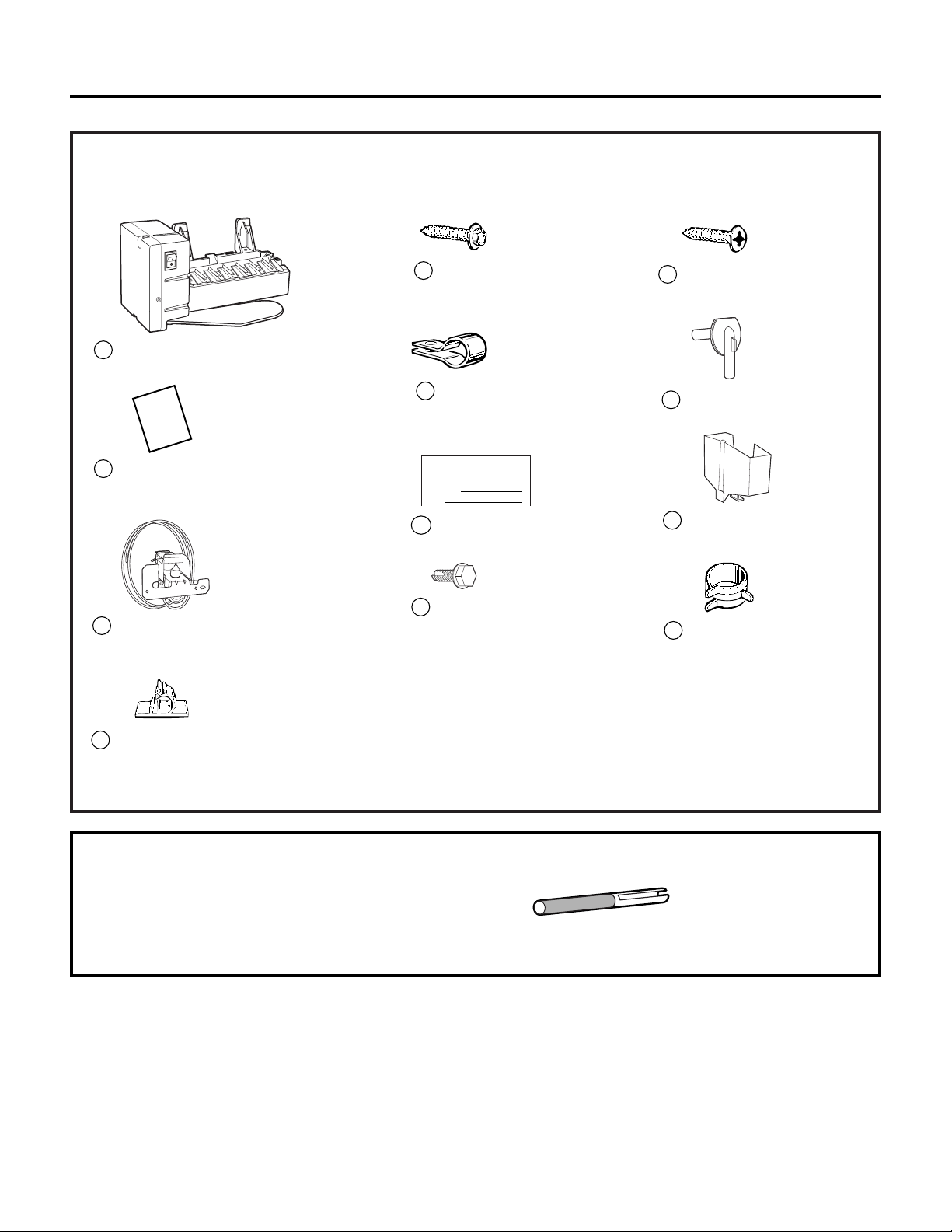
NEEDED CONTENTS OF KIT
The following are a list of the parts from the kit that will be needed to install the icemaker.
Owner’s Manual &
Installation Instructions
2
Water Line Clamp
(strain relief), for house
water line
6
Hex-Head Screw
for Water Line Clamp
5
Water Valve and
Tube Assembly
3
Hex-Head Screw, for
attaching water valve
8
Adhesive-Backed Water Tube
Fasteners, to secure plastic
water tube (4)
4
10
Water Tube Inlet
9
Phillips Head Screws,
for mounting icemaker (2)
Warranty Label
7
ICEMAKER
WARRANTY VERIFICATION
Date Installed
Dealer
11
Icemaker Fill Cup
(side-mounted)
Icemaker
1
In
s
ta
lla
t
io
n
In
s
t
r
u
c
tio
n
s
12
Hose Clamp
Installation Instructions
PARTS REQUIRED THAT CAME WITH THE REFRIGERATOR
If the fill tube has been misplaced,
call 1.800.626.2002 and order part WR02X11712.
Fill Tube with Foil
(5/8″ O.D.)
Page 3
3
Installation Instructions
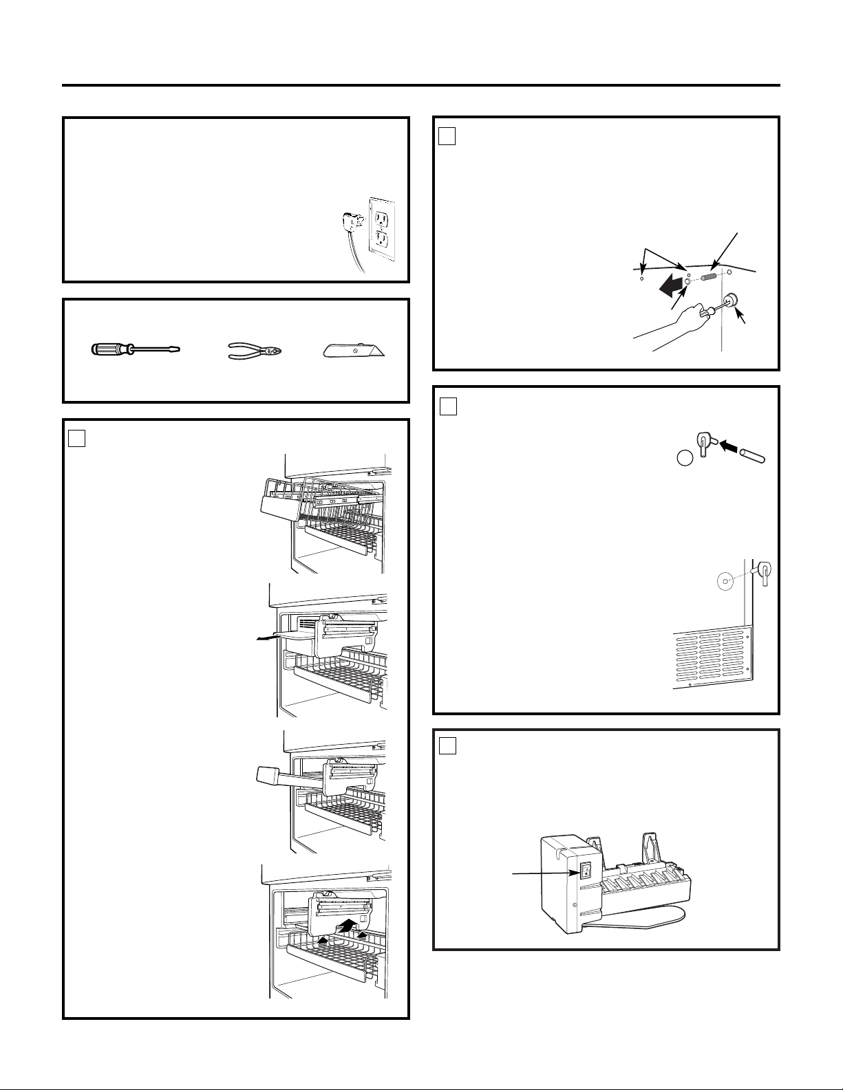
BEFORE YOU BEGIN
Read each step thoroughly before proceeding.
•
CAUTION – Unplug the
Refrigerator. To eliminate the danger
of electric shock during installation,
you must unplug the refrigerator from
its electrical outlet.
Flat blade and Phillips
screwdrivers
Pliers
TOOLS YOU WILL NEED
Sharp knife
INSTALL FILL TUBE
• Slide the fill tube shipped
with the refrigerator onto the
water tube inlet (10). If the fill
tube has been misplaced, call
1.800.626.2002 and order part
WR02X11712.
• Go to the back of the refrigerator.
Remove the label covering the
hole. Pull out the insulation plug
and any debris.
• On the tube side of the water
tube inlet (10), there is an
adhesive backing. Remove the
adhesive backing and slide the
tube into the hole at the back
of the refrigerator. Firmly press
on the inlet to secure it to the
refrigerator.
2
10
PREPARE FOR INSTALLATION (cont.)
• Inside the freezer, remove the two small white
plug buttons (on some models) from the side
wall. (If screws are present instead of plugs,
leave them in place.)
• Remove and discard
the large white plug
from the rear freezer
wall. Pull out the gray
insulation plug and
remove any debris.
• Remove the outlet
cover with a flat-blade
screwdriver.
3
Power
Switch
1
SET POWER SWITCH TO O (off)
Set the icemaker power switch to O (off). Leave
the power switch in the O (off) position until the
refrigerator is connected to the water supply to
prevent premature operation.
Outlet
cover
Remove side wall plug
buttons or leave screws
in place
Rear wall
plug button
Insulation
plug
PREPARE FOR INSTALLATION
• Remove the storage
basket (on some models)
by pulling it out to the
stop position and lifting
it up and out.
Note: After removing
the basket, push the
extension arms back
into the freezer
compartment.
• Remove the chiller shelf
(on some models) by
pulling it straight out.
• Remove the ice bucket
by pulling it out and
lifting it up and out.
• Remove the center
vertical shelf support
(on some models) by
lifting it and rotating
its bottom to the right.
1
Page 4

4
Installation Instructions
PLUG IN THE ICEMAKER
Holding the icemaker in place, insert the icemaker
power cord plug into the socket on the rear wall,
making sure the prongs and holes are matched.
Press the plug firmly into the socket. Lock the plug
in place by clipping the restraints onto each side of
the plug. Make sure the restraints click into place.
Make sure the power cord is still in the hook on
the back of the icemaker.
6
11
MOUNT THE ICEMAKER
• Lift the icemaker so the fill tube shipped with the
refrigerator fits in the fill cup opening (E). Hang
the icemaker on the two mounting screws (9) in
the side wall.
Make sure:
• The power cord is still firmly in the socket.
• The fill tube extends into the fill cup opening on
the back of the icemaker. (Check the rear of the
refrigerator to make sure the fill tube has not
been pushed out of the back of the refrigerator).
• The icemaker mounting screws are located in
the uppermost position of the mounting slots.
• The icemaker is level.
• The icemaker power switch is set to O (off).
THEN SECURELY TIGHTEN THE ICEMAKER
MOUNTING SCREWS.
7
E
9
RE-INSTALL THE SHELF SUPPORT,
BUCKET, SHELF AND BASKET
Replace the center vertical shelf support, ice bucket,
chiller shelf and storage basket by reversing the steps
in Step 1.
8
ATTACH WARRANTY LABEL
A label (7) is provided with this kit to record the
date of installation for warranty purposes. Apply it
to the back of the refrigerator.
9
KEEP THIS ADDENDUM
Keep this addendum with your Refrigerator
Owner’s Manual and Installation Instructions.
The icemaker installation inside the freezer is now
complete. Continue to the Water Valve Assembly
section.
10
INSTALL THE ICEMAKER FILL CUP
Install the icemaker fill cup (side-mounted) (11)
into the icemaker as shown.
5
INSTALL THE MOUNTING SCREWS
• Skip to Step 5 if screws are already in place in
the freezer side wall.
• Install two self-tapping Phillips
head screws (9) from the kit
in the holes in the side wall.
The screw heads should extend
about 1/2″ (13 mm) from the
side wall.
4
Hook
Page 5

5
Installation Instructions
BEFORE YOU BEGIN
Read each step thoroughly before proceeding.
•
CAUTION – Unplug the
Refrigerator. To eliminate the danger
of electric shock during installation,
you must unplug the refrigerator
from its electrical outlet.
WATER VALVE ASSEMBLY INSTALLATION INSTRUCTIONS
Flat blade and Phillips
screwdrivers
Pliers
TOOLS YOU WILL NEED
Sharp knife
1/4″ and 5/16″ Nutdrivers
REMOVE THE COVER
At the bottom rear of the refrigerator, remove the
screws holding the access cover.
Bend the cover back to access the compartment.
Be sure to save the screws as the access cover must
be reinstalled later to ensure that your refrigerator
will function properly.
1
CUT PLASTIC WATER TUBING
• Measure 25″ (64 cm) of water tubing starting
from where it is secured to the water valve.
Cut off excess tubing with a sharp knife or
single-edge razor blade.
2
25″ (64 cm)
Tape measure
• Fasten the water valve to the cabinet by driving
the hex-head screw (8) from the kit into the
hole in the cabinet leg.
ATTACH THE WATER VALVE
• Locate the female connector plug (C).
3
• Plug the female connector (C) onto the male
terminals on the water valve (3). Either wire
can go on either terminal.
C
3
8
C
Cabinet
Water valve
bracket
Hex-head
screw
Page 6

Installation Instructions
WATER VALVE INSTALLED
Refer to the Water Line Installation Instructions for
connection to the home water supply. After water
line installation is completed, set the icemaker
power switch to I (on).
Even when the icemaker power switch is in the
I (on) position, power to the icemaker will be
interrupted when the freezer door/drawer is open.
This prevents ice ejecting from the icemaker from
missing the ice bucket and dropping into the back
of the freezer. Because power to the icemaker is
interrupted while the door/drawer is open, the
green power light on the icemaker will be off. To
make sure the icemaker is working properly, press
the freezer light switch located on the upper right
side of the freezer compartment. The power light
on the icemaker will come on.
Note: After installing the icemaker, do not open
the door/drawer for approximately 4 hours. This
will allow the freezer to reach the correct operating
temperature for making ice, and will prevent water
from spilling out of the icemaker mold.
7
ROUTE AND ATTACH THE
WATER TUBE
• Fasten the plastic water tube to the back of the
refrigerator with three of the adhesive-backed
fasteners (4), spacing the fasteners as shown.
6
Adhesive-backed
fasteners for
water tube
INSTALL WATER LINE CLAMP
• Attach the water line clamp (strain relief) (6)
from the kit to the refrigerator. With the clamp
directly in line with the water valve, drive the
screw (5) from the kit through the clamp (6)
at the indent into the back of the cabinet.
• The metal clamp is for the house water line (see
Water Line Installation Instructions). It is not to
be used for the water tube from the water valve
up to the inlet.
5
5
6
CONNECT WATER TUBE
TO INLET
• Squeeze the ends of the hose clamp (12) from the
kit with pliers and slide the clamp over the inlet,
located on the right side of the refrigerator.
• While still squeezing the clamp, insert the free end
of the water tube (3) into the inlet as far as it will go.
• Then slide the clamp downward to capture the
water tube in place.
• Using one of the adhesive-backed fasteners (4),
secure the water tube to the back of the refrigerator
about 1/2″ below the inlet.
4
12
4
Inlet
3
ATTACH THE WATER VALVE (cont.)
• Clip the end of the ground wire to the
refrigerator cabinet.
3
Proceed with the appropriate step in the Installing
the Water Line section in the Owner’s Manual and
Installation Instructions to complete the installation.
IMPORTANT: To ensure a proper ground,
the end of the ground wire MUST be secured
to the refrigerator cabinet.
6
Page 7

7
Notes
Page 8

8
Printed in Mexico
 Loading...