

Page 1
830715A2.CDR
g
GE Industrial Systems
Title Pag e
IISO9001:2000
G
E
M
U
L
T
I
L
I
N
R
E
G
I
S
T
E
R
E
D
LISTED
52TL
IND.CONT. EQ.
E83849
G60 Generator Protection System
UR Series Instruction Manual
G60 revision: 5.7x
Manual P/N: 1601-0110-U3 (GEK-113523B)
Copyright © 2010 GE Multilin
GE Multilin
215 Anderson Avenue, Markham, Ontario
Canada L6E 1B3
Tel: (905) 294-6222 Fax: (905) 201-2098
Internet: http://www.GEmultilin.com
*1601-0110-U3*
GE Multilin's Quality Management
System is registered to
ISO9001:2000
QMI # 005094
UL # A3775
Page 2

Page 3

g
GE Industrial Systems
Addendum
ADDENDUM
This addendum contains information that relates to the G60 Generator Protection System, version 5.7x. This addendum
lists a number of information items that appear in the instruction manual GEK-113523B (revision U3) but are not
included in the current G60 operations.
The following functions and items are not yet available with the current version of the G60 relay:
• Signal sources SRC 5 and SRC 6.
Version 4.0x and higher releases of the G60 relay includes new hardware (CPU and CT/VT modules).
• The new CPU modules are specified with the following order codes: 9E, 9G, 9H, 9J, 9K, 9L, 9M, 9N, 9P, 9R, and 9S.
• The new CT/VT modules are specified with the follow ing order codes: 8F, 8G, 8H, 8J 8L, 8M, 8N, 8R.
The following table maps the relationship between the old CPU and CT/VT modules to the newer versions:
MODULE OLD NEW DESCRIPTION
CPU 9A 9E RS485 and RS485 (Modbus RTU, DNP)
9C 9G RS485 and 10Base-F (Ethernet, Modbus TCP/IP, DNP)
9D 9H RS485 and redundant 10Base-F (Ethernet, Modbus TCP/IP, DNP)
--- 9J RS485 and multi-mode ST 100Base-FX
--- 9K RS485 and multi-mode ST redundant 100Base-FX
--- 9L RS485 and single mode SC 100Base-FX
--- 9M RS485 and single mode SC redundant 100Base-FX
--- 9N RS485 and 10/100Base-T
--- 9P RS485 and single mode ST 100Base-FX
--- 9R RS485 and single mode ST redundant 100Base-FX
--- 9S RS485 and six-port managed Ethernet switch
CT/VT 8A 8F Standard 4CT/4VT
8B 8G Sensitive ground 4CT/4VT
8C 8H Standard 8CT
8D 8J Sensitive ground 8CT
-- 8L Standard 4CT/4VT with enhanced diagnostics
-- 8M Sensitive ground 4CT/4VT with enhanced diagnostics
-- 8N Standard 8CT with enhanced diagnostics
-- 8R Sensitive ground 8CT with enhanced diagnostics
The new CT/VT modules can only be used with the new CPUs (9E, 9G, 9H, 9J, 9K, 9L, 9M, 9N, 9P, 9R, and 9S), and
the old CT/VT modules can only be used with the old CPU modules (9A, 9C, 9D). To prevent any hardware mismatches, the new CPU and CT/VT modules have blue labels and a warni ng sticker stating “Attn.: Ensure C PU and
DSP module label colors are the same!”. In the event that there is a mismatch between the CPU and CT/VT module,
the relay will not function and a
All other input/output modules are compatible with the new hardware.
With respect to the firmware, firmware versions 4.0x and higher are only compatible with the new CPU and CT/VT mod-
ules. Previous versions of the firmware (3.4x and earlier) are only compatible with the older CPU and CT/VT modules.
DSP ERROR or HARDWARE MISMATCH error will be displayed.
Page 4

Page 5

Table of Contents
TABLE OF CONTENTS
1. GETTING STARTED 1.1 IMPORTANT PROCEDURES
1.1.1 CAUTIONS AND WARNINGS...........................................................................1-1
1.1.2 INSPECTION CHECKLIST................................................................................1-1
1.2 UR OVERVIEW
1.2.1 INTRODUCTION TO THE UR...........................................................................1-2
1.2.2 HARDWARE ARCHITECTURE......................................................................... 1-3
1.2.3 SOFTWARE ARCHITECTURE......................................................................... .1-4
1.2.4 IMPORTANT CONCEPTS................................................................................. 1-4
1.3 ENERVISTA UR SETUP SOFTWARE
1.3.1 PC REQUIREMENTS........................................................................................1-5
1.3.2 INSTALLATION..................................................................................................1-5
1.3.3 CONFIGURING THE G60 FOR SOFTWARE ACCESS....................................1-7
1.3.4 USING THE QUICK CONNECT FEATURE.......................................................1-9
1.3.5 CONNECTING TO THE G60 RELAY..............................................................1-15
1.4 UR HARDWARE
1.4.1 MOUNTING AND WIRING.................................................... ... ........................ 1-16
1.4.2 COMMUNICATIONS........................................................................................1-16
1.4.3 FACEPLATE DISPLAY.............................................. .... ... ...............................1-16
1.5 USING THE RELAY
1.5.1 FACEPLATE KEYPAD............................................................. ........................ 1-17
1.5.2 MENU NAVIGATION ..................................................... ... ...............................1-17
1.5.3 MENU HIERARCHY .................................................................................. ...... 1-17
1.5.4 RELAY ACTIVATION....................................................................................... 1-17
1.5.5 RELAY PASSWORDS.....................................................................................1-18
1.5.6 FLEXLOGIC™ CUSTOMIZATION........................................ ... .... .................... 1-18
1.5.7 COMMISSIONING...........................................................................................1-19
2. PRODUCT DESCRIPTION 2.1 INTRODUCTION
2.1.1 OVERVIEW........................................................................................................2-1
2.1.2 ORDERING........................................................................................................2-3
2.1.3 REPLACEMENT MODULES .............................................................................2-7
2.2 SPECIFICATIONS
2.2.1 PROTECTION ELEMENTS.......................................................................... ...2-10
2.2.2 USER-PROGRAMMABLE ELEMENTS...........................................................2-14
2.2.3 MONITORING.................................................................................................. 2-15
2.2.4 METERING...................................................................................................... 2-15
2.2.5 INPUTS............................................................................................................2-16
2.2.6 POWER SUPPLY ...................................................... .... ..................................2-17
2.2.7 OUTPUTS........................................................................................................2-17
2.2.8 COMMUNICATIONS........................................................................................2-18
2.2.9 INTER-RELAY COMMUNICATIONS...............................................................2-20
2.2.10 ENVIRONMENTAL ..........................................................................................2-20
2.2.11 TYPE TESTS ...................................................................................................2-21
2.2.12 PRODUCTION TESTS .................................................................................... 2-21
2.2.13 APPROVALS ................................................................................................... 2-22
2.2.14 MAINTENANCE ...............................................................................................2-22
3. HARDWARE 3.1 DESCRIPTION
3.1.1 PANEL CUTOUT ...............................................................................................3-1
3.1.2 MODULE WITHDRAWAL AND INSERTION.....................................................3-6
3.1.3 REAR TERMINAL LAYOUT...............................................................................3-8
3.2 WIRING
3.2.1 TYPICAL WIRING............................................................................................ 3-10
3.2.2 DIELECTRIC STRENGTH...............................................................................3-11
3.2.3 CONTROL POWER.........................................................................................3-11
3.2.4 CT/VT MODULES.......................................................... ..................................3-12
3.2.5 PROCESS BUS MODULES ........................................................ .................... 3-14
3.2.6 CONTACT INPUTS AND OUTPUTS...............................................................3-14
GE Multilin G60 Generator Protection System v
Page 6

TABLE OF CONTENTS
3.2.7 TRANSDUCER INPUTS/OUTPUTS.................................................................3-22
3.2.8 RS232 FACEPLATE PORT..............................................................................3-23
3.2.9 CPU COMMUNICATION PORTS.....................................................................3-23
3.2.10 IRIG-B...............................................................................................................3-27
3.3 DIRECT INPUT/OUTPUT COMMUNICATIONS
3.3.1 DESCRIPTION.................................................................................................3-28
3.3.2 FIBER: LED AND ELED TRANSMITTERS......................................................3-30
3.3.3 FIBER-LASER TRANSMITTERS.....................................................................3-30
3.3.4 G.703 INTERFACE...........................................................................................3-31
3.3.5 RS422 INTERFACE .........................................................................................3-34
3.3.6 RS422 AND FIBER INTERFACE.....................................................................3-36
3.3.7 G.703 AND FIBER INTERFACE ......................................................................3-36
3.3.8 IEEE C37.94 INTERFACE................................................................................3-37
3.3.9 C37.94SM INTERFACE ...................................................................................3-39
3.4 MANAGED ETHERNET SWITCH MODULES
3.4.1 OVERVIEW ......................................................................................................3-41
3.4.2 MANAGED ETHERNET SWITCH MODULE HARDWARE..............................3-41
3.4.3 MANAGED SWITCH LED INDICATORS.........................................................3-42
3.4.4 CONFIGURING THE MANAGED ETHERNET SWITCH MODULE.................3-42
3.4.5 UPLOADING G60 SWITCH MODULE FIRMWARE.........................................3-45
3.4.6 ETHERNET SWITCH SELF-TEST ERRORS...................................................3-47
4. HUMAN INTERFACES 4.1 ENERVISTA UR SETUP SOFTWARE INTERFACE
4.1.1 INTRODUCTION ................................................................................................4-1
4.1.2 CREATING A SITE LIST....................................................................................4-1
4.1.3 ENERVISTA UR SETUP OVERVIEW................................................................4-1
4.1.4 ENERVISTA UR SETUP MAIN WINDOW.............................. ... .........................4-3
4.2 EXTENDED ENERVISTA UR SETUP FEATURES
4.2.1 SETTINGS TEMPLATES ...................................................................................4-4
4.2.2 SECURING AND LOCKING FLEXLOGIC™ EQUATIONS................................4-8
4.2.3 SETTINGS FILE TRACEABILITY.....................................................................4-10
4.3 FACEPLATE INTERFACE
4.3.1 FACEPLATE.....................................................................................................4-13
4.3.2 LED INDICATORS............................................................................................4-14
4.3.3 CUSTOM LABELING OF LEDS.......................................................................4-17
4.3.4 DISPLAY...........................................................................................................4-23
4.3.5 KEYPAD ...........................................................................................................4-23
4.3.6 BREAKER CONTROL................................................................... ...................4-23
4.3.7 MENUS.............................................................................................................4-24
4.3.8 CHANGING SETTINGS ...................................................................................4-26
5. SETTINGS 5.1 OVERVIEW
5.1.1 SETTINGS MAIN MENU....................................................................................5-1
5.1.2 INTRODUCTION TO ELEMENTS......................................................................5-4
5.1.3 INTRODUCTION TO AC SOURCES..................................................................5-5
5.2 PRODUCT SETUP
5.2.1 SECURITY..........................................................................................................5-8
5.2.2 DISPLAY PROPERTIES ..................................................................................5-12
5.2.3 CLEAR RELAY RECORDS..............................................................................5-14
5.2.4 COMMUNICATIONS........................................................................................5-15
5.2.5 MODBUS USER MAP......................................................................................5-36
5.2.6 REAL TIME CLOCK .........................................................................................5-37
5.2.7 USER-PROGRAMMABLE FAULT REPORT....................................................5-38
5.2.8 OSCILLOGRAPHY...........................................................................................5-39
5.2.9 DATA LOGGER................................................................................................5-41
5.2.10 USER-PROGRAMMABLE LEDS .....................................................................5-42
5.2.11 USER-PROGRAMMABLE SELF TESTS .........................................................5-45
5.2.12 CONTROL PUSHBUTTONS ............................................................................5-46
5.2.13 USER-PROGRAMMABLE PUSHBUTTONS....................................................5-47
vi G60 Generator Protection System GE Multilin
Page 7

TABLE OF CONTENTS
5.2.14 FLEX STATE PARAMETERS.......................................................................... 5-52
5.2.15 USER-DEFINABLE DISPLAYS .......................................................................5-53
5.2.16 DIRECT INPUTS/OUTPUTS ...........................................................................5-55
5.2.17 TELEPROTECTION.........................................................................................5-63
5.2.18 INSTALLATION ................................................................................................ 5-63
5.3 REMOTE RESOURCES
5.3.1 REMOTE RESOURCES CONFIGURATION...................................................5-65
5.4 SYSTEM SETUP
5.4.1 AC INPUTS......................................................................................................5-66
5.4.2 POWER SYSTEM........................................................................ ... ................. 5-67
5.4.3 SIGNAL SOURCES......................................................................................... 5-68
5.4.4 BREAKERS......................................................................................................5-71
5.4.5 DISCONNECT SWITCHES .............................................................................5-75
5.4.6 FLEXCURVES................................................................................................. 5-78
5.4.7 PHASOR MEASUREMENT UNIT....................................................................5-85
5.5 FLEXLOGIC™
5.5.1 INTRODUCTION TO FLEXLOGIC™............................................................. 5-101
5.5.2 FLEXLOGIC™ RULES ..................................................................................5-112
5.5.3 FLEXLOGIC™ EVALUATION............................................... ......................... 5-112
5.5.4 FLEXLOGIC™ EXAMPLE .............................................................................5-113
5.5.5 FLEXLOGIC™ EQUATION EDITOR..................................................... .... ... .5-117
5.5.6 FLEXLOGIC™ TIMERS...................................................................... ... .... .... 5-117
5.5.7 FLEXELEMENTS™....................................................................................... 5-119
5.5.8 NON-VOLATILE LATCHES........................................................................... 5-123
5.6 GROUPED ELEMENTS
5.6.1 OVERVIEW....................................................................................................5-124
5.6.2 SETTING GROUP .........................................................................................5-124
5.6.3 DISTANCE.....................................................................................................5-125
5.6.4 POWER SWING DETECT............................................................................. 5-133
5.6.5 STATOR DIFFERENTIAL.............................................................................. 5-141
5.6.6 PHASE CURRENT ........................................................................................ 5-144
5.6.7 NEUTRAL CURRENT....................................................... .... ... ...................... 5-155
5.6.8 GROUND CURRENT..................................................................................... 5-162
5.6.9 NEGATIVE SEQUENCE CURRENT ............................................................. 5-169
5.6.10 GENERATOR UNBALANCE .........................................................................5-172
5.6.11 SPLIT PHASE PROTECTION .......................................................................5-174
5.6.12 VOLTAGE ELEMENTS.................................................................................. 5-178
5.6.13 LOSS OF EXCITATION.................................................................................5-188
5.6.14 ACCIDENTAL ENERGIZATION ....................................................................5-190
5.6.15 SENSITIVE DIRECTIONAL POWER.............................................................5-192
5.6.16 STATOR GROUND........................................................................................5-195
5.7 CONTROL ELEMENTS
5.7.1 OVERVIEW....................................................................................................5-201
5.7.2 TRIP BUS.......................................................................................................5-201
5.7.3 SETTING GROUPS.......................................................................................5-203
5.7.4 SELECTOR SWITCH.....................................................................................5-204
5.7.5 UNDERFREQUENCY....................................................................................5-210
5.7.6 OVERFREQUENCY ......................................................................................5-211
5.7.7 FREQUENCY RATE OF CHANGE................................................................ 5-212
5.7.8 FREQUENCY OUT-OF-BAND ACCUMULATION.........................................5-214
5.7.9 SYNCHROCHECK.........................................................................................5-216
5.7.10 DIGITAL ELEMENTS..................................................................................... 5-221
5.7.11 DIGITAL COUNTERS ......................................... .... ... ....................................5-224
5.7.12 MONITORING ELEMENTS ...................... ... ..................................................5-226
5.8 INPUTS/OUTPUTS
5.8.1 CONTACT INPUTS........................................................................................5-227
5.8.2 VIRTUAL INPUTS.......................................................................................... 5-229
5.8.3 CONTACT OUTPUTS....................................................................................5-230
5.8.4 VIRTUAL OUTPUTS...................................................................................... 5-232
5.8.5 REMOTE DEVICES.......................................................................................5-233
5.8.6 REMOTE INPUTS..........................................................................................5-234
5.8.7 REMOTE DOUBLE-POINT STATUS INPUTS.............................................. 5-235
5.8.8 REMOTE OUTPUTS......................................................................................5-235
5.8.9 RESETTING...................................................................................................5-236
GE Multilin G60 Generator Protection System vii
Page 8

TABLE OF CONTENTS
5.8.10 DIRECT INPUTS AND OUTPUTS............................................................... ...5-237
5.8.11 TELEPROTECTION INPUTS AND OUTPUTS ..............................................5-240
5.8.12 IEC 61850 GOOSE ANALOGS ......................................................................5-242
5.8.13 IEC 61850 GOOSE INTEGERS .....................................................................5-243
5.9 TRANSDUCER INPUTS AND OUTPUTS
5.9.1 DCMA INPUTS................................................................... .... ... .....................5-244
5.9.2 RTD INPUTS....................................... ... ........................................................5-245
5.9.3 RRTD INPUTS............................................................. ...................................5-247
5.9.4 DCMA OUTPUTS................................................................... ........................5-251
5.10 TESTING
5.10.1 TEST MODE...................................................................................................5-255
5.10.2 FORCE CONTACT INPUTS...........................................................................5-256
5.10.3 FORCE CONTACT OUTPUTS.......................................................................5-257
5.10.4 PHASOR MEASUREMENT UNIT TEST VALUES.........................................5-258
6. ACTUAL VALUES 6.1 OVERVIEW
6.1.1 ACTUAL VALUES MAIN MENU.........................................................................6-1
6.2 STATUS
6.2.1 CONTACT INPUTS............................................................................................6-4
6.2.2 VIRTUAL INPUTS ..............................................................................................6-4
6.2.3 REMOTE INPUTS..............................................................................................6-4
6.2.4 REMOTE DOUBLE-POINT STATUS INPUTS...................................................6-5
6.2.5 TELEPROTECTION INPUTS.............................................................................6-5
6.2.6 CONTACT OUTPUTS........................................................................................6-5
6.2.7 VIRTUAL OUTPUTS ..........................................................................................6-6
6.2.8 REMOTE DEVICES............................................................................................6-6
6.2.9 DIGITAL COUNTERS.........................................................................................6-7
6.2.10 SELECTOR SWITCHES ....................................................................................6-7
6.2.11 FLEX STATES....................................................................................................6-7
6.2.12 ETHERNET ........................................................................................................6-7
6.2.13 DIRECT INPUTS ....................................................................... .... ... ..................6-8
6.2.14 DIRECT DEVICES STATUS ......................... .... .................................................6-8
6.2.15 IEC 61850 GOOSE INTEGERS .........................................................................6-9
6.2.16 EGD PROTOCOL STATUS................................................................................6-9
6.2.17 TELEPROTECTION CHANNEL TESTS...........................................................6-10
6.2.18 ETHERNET SWITCH .......................................................................................6-10
6.3 METERING
6.3.1 METERING CONVENTIONS ...........................................................................6-11
6.3.2 STATOR DIFFERENTIAL.................................................................................6-14
6.3.3 SOURCES........................................................................................................6-14
6.3.4 SYNCHROCHECK ...........................................................................................6-18
6.3.5 TRACKING FREQUENCY................................................................................6-18
6.3.6 FREQUENCY RATE OF CHANGE..................................................................6-19
6.3.7 FREQUENCY OUT-OF-BAND ACCUMULATION............................................6-19
6.3.8 FLEXELEMENTS™..........................................................................................6-19
6.3.9 IEC 61580 GOOSE ANALOG VALUES ...........................................................6-20
6.3.10 SENSITIVE DIRECTIONAL POWER ...............................................................6-20
6.3.11 STATOR GROUND ..........................................................................................6-21
6.3.12 VOLTS PER HERTZ.........................................................................................6-21
6.3.13 RESTRICTED GROUND FAULT......................................................................6-21
6.3.14 PHASOR MEASUREMENT UNIT ....................................................................6-21
6.3.15 TRANSDUCER INPUTS AND OUTPUTS........................................................6-22
6.4 RECORDS
6.4.1 USER-PROGRAMMABLE FAULT REPORTS.................................................6-23
6.4.2 EVENT RECORDS...........................................................................................6-23
6.4.3 OSCILLOGRAPHY...........................................................................................6-23
6.4.4 DATA LOGGER................................................................................................6-24
6.4.5 PHASOR MEASUREMENT UNIT RECORDS.................................................6-24
6.5 PRODUCT INFORMATION
6.5.1 MODEL INFORMATION ...................................................................................6-25
6.5.2 FIRMWARE REVISIONS................................................. ... .... ..........................6-25
viii G60 Generator Protection System GE Multilin
Page 9

TABLE OF CONTENTS
7. COMMANDS AND
TARGETS
7.1 COMMANDS
7.1.1 COMMANDS MENU..........................................................................................7-1
7.1.2 VIRTUAL INPUTS..............................................................................................7-1
7.1.3 CLEAR RECORDS............................................................................................ 7-2
7.1.4 SET DATE AND TIME .......................................................................................7-2
7.1.5 RELAY MAINTENANCE.................................................................................... 7-3
7.1.6 PHASOR MEASUREMENT UNIT ONE-SHOT.................................................. 7-4
7.2 TARGETS
7.2.1 TARGETS MENU.................................................... ...........................................7-6
7.2.2 TARGET MESSAGES .......................................................................................7-6
7.2.3 RELAY SELF-TESTS.........................................................................................7-6
8. SECURITY 8.1 PASSWORD SECURITY
8.1.1 OVERVIEW........................................................................................................8-1
8.1.2 PASSWORD SECURITY MENU ....................................................................... 8-2
8.1.3 LOCAL PASSWORDS.......................................................................................8-2
8.1.4 REMOTE PASSWORDS ...................................................................................8-3
8.1.5 ACCESS SUPERVISION...................................................................................8-3
8.1.6 DUAL PERMISSION SECURITY ACCESS....................................................... 8-4
8.2 SETTINGS SECURITY
8.2.1 SETTINGS TEMPLATES................................................................................... 8-6
8.2.2 SECURING AND LOCKING FLEXLOGIC™ EQUATIONS .............................8-10
8.2.3 SETTINGS FILE TRACEABILITY.................................................................... 8-12
8.3 ENERVISTA SECURITY MANAGEMENT SYSTEM
8.3.1 OVERVIEW......................................................................................................8-15
8.3.2 ENABLING THE SECURITY MANAGEMENT SYSTEM.................................8-15
8.3.3 ADDING A NEW USER ...................................................................................8-15
8.3.4 MODIFYING USER PRIVILEGES ................................................................... 8-16
9. THEORY OF OPERATION 9.1 PHASE DISTANCE THROUGH POWER TRANSFORMERS
9.1.1 DESCRIPTION...................................................................................................9-1
9.1.2 EXAMPLE..........................................................................................................9-4
10. APPLICATION OF
SETTINGS
10.1 SETTING EXAMPLE
10.1.1 DESCRIPTION.................................................................................................10-1
10.1.2 SYSTEM SETUP ............................................................................................. 10-1
10.1.3 POWER SYSTEM............................................................................................10-2
10.1.4 SIGNAL SOURCES .........................................................................................10-2
10.1.5 STATOR DIFFERENTIAL................................................................................10-3
10.1.6 GENERATOR UNBALANCE ...........................................................................10-3
10.1.7 LOSS OF EXCITATION...................................................................................10-4
10.1.8 REVERSE POWER ....................... ..................................................................10-4
10.1.9 SYSTEM BACKUP OVERCURRENT.............................................................. 10-5
10.1.10 BACKUP DISTANCE.......................................................................................10-6
10.1.11 STATOR GROUND FAULT............................................................................. 10-7
10.1.12 OVEREXCITATION....................................................................................... 10-10
10.1.13 INPUTS/OUTPUTS........................................................................................10-11
10.1.14 FREQUENCY................................................................................................. 10-12
10.1.15 ACCIDENTAL ENERGIZATION ....................................................................10-12
10.1.16 FLEXLOGIC™...............................................................................................10-13
10.2 PHASE DISTANCE THROUGH POWER TRANSFORMERS
10.2.1 OVERVIEW....................................................................................................10-14
10.2.2 EXAMPLE ......................................................................................................10-15
GE Multilin G60 Generator Protection System ix
Page 10

TABLE OF CONTENTS
11. COMMISSIONING 11.1 TESTING
11.1.1 TESTING UNDERFREQUENCY AND OVERFREQUENCY ELEMENTS .......11-1
A. FLEXANALOG AND
FLEXINTEGER
PARAMETERS
B. MODBUS
COMMUNICATIONS
A.1 PARAMETER LISTS
A.1.1 FLEXANALOG ITEMS....................................................................................... A-1
A.1.2 FLEXINTEGER ITEMS.................................................................................... A-11
B.1 MODBUS RTU PROTOCOL
B.1.1 INTRODUCTION ...............................................................................................B-1
B.1.2 PHYSICAL LAYER.............................. ... ...........................................................B-1
B.1.3 DATA LINK LAYER ...........................................................................................B-1
B.1.4 CRC-16 ALGORITHM ....................................................................................... B-2
B.2 MODBUS FUNCTION CODES
B.2.1 SUPPORTED FUNCTION CODES................................................................... B-3
B.2.2 READ ACTUAL VALUES OR SETTINGS (FUNCTION CODE 03/04H) ...........B-3
B.2.3 EXECUTE OPERATION (FUNCTION CODE 05H)...........................................B-4
B.2.4 STORE SINGLE SETTING (FUNCTION CODE 06H).......................................B-4
B.2.5 STORE MULTIPLE SETTINGS (FUNCTION CODE 10H)................................B-5
B.2.6 EXCEPTION RESPONSES...............................................................................B-5
B.3 FILE TRANSFERS
B.3.1 OBTAINING RELAY FILES VIA MODBUS........................................................B-6
B.3.2 MODBUS PASSWORD OPERATION...............................................................B-7
B.4 MEMORY MAPPING
B.4.1 MODBUS MEMORY MAP.................................................................................B-8
B.4.2 DATA FORMATS.............................................................................................B-65
C. IEC 61850
COMMUNICATIONS
C.1 OVERVIEW
C.1.1 INTRODUCTION...............................................................................................C-1
C.1.2 COMMUNICATION PROFILES.........................................................................C-1
C.2 SERVER DATA ORGANIZATION
C.2.1 OVERVIEW.......................................................................................................C-2
C.2.2 GGIO1: DIGITAL STATUS VALUES .................................................................C-2
C.2.3 GGIO2: DIGITAL CONTROL VALUES..............................................................C-2
C.2.4 GGIO3: DIGITAL STATUS AND ANALOG VALUES FROM RECEIVED GOOSE
DATAC-2
C.2.5 GGIO4: GENERIC ANALOG MEASURED VALUES.........................................C-2
C.2.6 MMXU: ANALOG MEASURED VALUES ..........................................................C-3
C.2.7 PROTECTION AND OTHER LOGICAL NODES...............................................C-3
C.3 SERVER FEATURES AND CONFIGURATION
C.3.1 BUFFERED/UNBUFFERED REPORTING........................................................C-5
C.3.2 FILE TRANSFER...............................................................................................C-5
C.3.3 TIMESTAMPS AND SCANNING...................................................... .... ... ..........C-5
C.3.4 LOGICAL DEVICE NAME .................................................................................C-5
C.3.5 LOCATION........................................................................................................C-5
C.3.6 LOGICAL NODE NAME PREFIXES..................................................................C-6
C.3.7 CONNECTION TIMING.....................................................................................C-6
C.3.8 NON-IEC 61850 DATA......................................................................................C-6
C.3.9 COMMUNICATION SOFTWARE UTILITIES.....................................................C-6
C.4 GENERIC SUBSTATION EVENT SERVICES: GSSE AND GOOSE
C.4.1 OVERVIEW.......................................................................................................C-7
C.4.2 GSSE CONFIGURATION..................................................................................C-7
C.4.3 FIXED GOOSE....................................... .... .......................................................C-7
C.4.4 CONFIGURABLE GOOSE................................................................................C-7
C.4.5 ETHERNET MAC ADDRESS FOR GSSE/GOOSE..........................................C-9
x G60 Generator Protection System GE Multilin
Page 11

TABLE OF CONTENTS
C.4.6 GSSE ID AND GOOSE ID SETTINGS............................................................C-10
C.5 IEC 61850 IMPLEMENTATION VIA ENERVISTA UR SETUP
C.5.1 OVERVIEW......................................................................................................C-11
C.5.2 CONFIGURING IEC 61850 SETTINGS...........................................................C-12
C.5.3 ABOUT ICD FILES...........................................................................................C-13
C.5.4 CREATING AN ICD FILE WITH ENERVISTA UR SETUP..............................C-17
C.5.5 ABOUT SCD FILES.........................................................................................C-17
C.5.6 IMPORTING AN SCD FILE WITH ENERVISTA UR SETUP...........................C-20
C.6 ACSI CONFORMANCE
C.6.1 ACSI BASIC CONFORMANCE STATEMENT.................................................C-22
C.6.2 ACSI MODELS CONFORMANCE STATEMENT............................................C-22
C.6.3 ACSI SERVICES CONFORMANCE STATEMENT .........................................C-23
C.7 LOGICAL NODES
C.7.1 LOGICAL NODES TABLE...............................................................................C-26
D. IEC 60870-5-104
COMMUNICATIONS
D.1 IEC 60870-5-104
D.1.1 INTEROPERABILITY DOCUMENT ...................................................................D-1
D.1.2 IEC 60870-5-104 POINT LIST ...........................................................................D-9
E. DNP COMMUNICATIONS E.1 DEVICE PROFILE DOCUMENT
E.1.1 DNP V3.00 DEVICE PROFILE ................................................ .... ......................E-1
E.1.2 IMPLEMENTATION TABLE...............................................................................E-4
E.2 DNP POINT LISTS
E.2.1 BINARY INPUT POINTS....................................................................................E-8
E.2.2 BINARY AND CONTROL RELAY OUTPUT......................................................E-9
E.2.3 COUNTERS.....................................................................................................E-10
E.2.4 ANALOG INPUTS............................................................................................E-11
F. MISCELLANEOUS F.1 CHANGE NOTES
F.1.1 REVISION HISTORY............................ .... ... ......................................................F-1
F.1.2 CHANGES TO THE G60 MANUAL ...................................................................F-2
F.2 ABBREVIATIONS
F.2.1 STANDARD ABBREVIATIONS ........................................................................ .F-6
F.3 WARRANTY
F.3.1 GE MULTILIN WARRANTY...............................................................................F-8
INDEX
GE Multilin G60 Generator Protection System xi
Page 12

TABLE OF CONTENTS
xii G60 Generator Protection System GE Multilin
Page 13

1 GETTING STARTED 1.1 IMPORTANT PROCEDURES
CAUTION
WARNING
®
®
Technical Support:
Tel: (905) 294-6222
Fax: (905) 201-2098
http://www.GEmultilin.com
Model:
Mods:
Wiring Diagram:
Inst. Manual:
Serial Number:
Firmware:
Mfg. Date:
G60D00HCHF8AH6AM6BP8BX7A
000
830721A3
GEK-113274
MAZB98000029
D
2005/01/05
Control Power:
Contact Inputs:
Contact Outputs:
88-300V DC @ 35W / 77-265V AC @ 35VA
300V DC Max 10mA
Standard Pilot Duty / 250V AC 7.5A
360V A Resistive / 125V DC Break
4A @ L/R = 40mS / 300W
RATINGS:
G60
Generator Management Relay
GE Multilin
Made in
Canada
- M A A B 9 7 0 0 0 0 9 9 -
830742A1.CDR
NOTE
1 GETTING STARTED 1.1IMPORTANT PROCEDURES
Please read this chapter to help guide you through the initial setup of your new relay.
1.1.1 CAUTIONS AND WARNINGS
Before attempting to install or use the relay, it is imperative that all WARNINGS and CAUTIONS
in this manual are reviewed to help prevent personal injury, equipment damage, and/or downtime.
1.1.2 INSPECTION CHECKLIST
1. Open the relay packaging and inspect the unit for physical damage.
2. View the rear nameplate and verify that the correct model has been ordered.
Figure 1–1: REAR NAMEPLATE (EXAMPLE)
3. Ensure that the following items are included:
• Instruction manual.
• GE EnerVista CD (includes the EnerVista UR Setup software and manuals in PDF format).
• Mounting screws.
For product information, instruction manual updates, and the latest software updates, please visit the GE Multilin website at
http://www.GEmultilin.com
.
If there is any noticeable physical damage, or any of the contents listed are missing, please contact GE
Multilin immediately.
1
GE MULTILIN CONTACT INFORMATION AND CALL CENTER FOR PRODUCT SUPPORT:
GE Multilin
215 Anderson Avenue
Markham, Ontario
Canada L6E 1B3
TELEPHONE: (905) 294-6222, 1-800-547-8629 (North America only)
FAX: (905) 201-2098
E-MAIL: gemultilin@ge.com
HOME PAGE: http://www.GEmultilin.com
GE Multilin G60 Generator Protection System 1-1
Page 14

1.2 UR OVERVIEW 1 GETTING STARTED
1.2UR OVERVIEW 1.2.1 INTRODUCTION TO THE UR
1
Historically, substation protection, control, and mete ring functions were performed with electromechan ical equipment. This
first generation of equipment was gradually replaced by analog electronic equipment, most of which emulated the singlefunction approach of their electromechanical precursors. Both of th ese technologi es required expensive cabling a nd auxiliary equipment to produce functioning systems.
Recently, digital electronic equipment has begun to provide protectio n, control, and metering functions. Initially, this equipment was either single function or had very limited multi-function capability, and did not significantly reduce the cabling and
auxiliary equipment required. However, recent digital relays have become quite multi-functional, reducing cabling and auxiliaries significantly. These devices also transfer data to central control facilities and Human Machine Interfaces using electronic communications. The functions performed by these pro ducts have become so broad that many users now prefer the
term IED (Intelligent Electronic Device).
It is obvious to station designers that the amount of cabling and auxiliary equipment installed in stations can be even further
reduced, to 20% to 70% of the levels common in 1990, to achieve large cost r eductions. This requires placing eve n more
functions within the IEDs.
Users of power equipment are also interested in reducing cost by improving power quality and pe rsonnel productivity, and
as always, in increasing system reliability and efficiency. These objectives are realized through software which is used to
perform functions at both the station and supervisory levels. The use of these systems is growing rapidly.
High speed communications are required to meet the data tr ansfer rates required by moder n automatic control and monitoring systems. In the near future, very high speed communications will be required to perform protection signaling with a
performance target response time for a command signal between two IEDs, from transmission to reception, of less than 3
milliseconds. This has been established by the IEC 61850 standard.
IEDs with the capabilities outlined above will also provide significantly more power system data than is presently available,
enhance operations and maintenance, and permit the use of adaptive system configuration for protection and control systems. This new generation of equipment must also be easily incorporated into automation systems, at both the station and
enterprise levels. The GE Multilin Universal Relay (UR) has been developed to meet these goals.
1-2 G60 Generator Protection System GE Multilin
Page 15
1 GETTING STARTED 1.2 UR OVERVIEW
827822A2.CDR
Input Elements
LAN
Programming
Device
Operator
Interface
Contact Inputs Contact Outputs
Virtual Inputs
Virtual Outputs
Analog Inputs
Analog Outputs
CT Inputs
VT Inputs
Input
Status
Table
Output
Status
Table
Pickup
Dropout
Operate
Protective Elements
Logic Gates
Remote Outputs
-DNA
-USER
CPU Module Output Elements
Remote Inputs
Direct Inputs
Direct Outputs
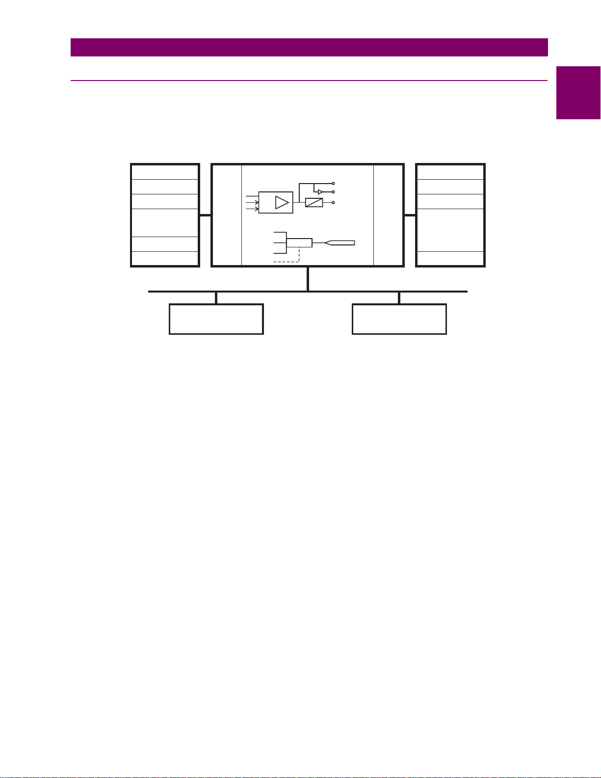
1.2.2 HARDWARE ARCHITECTURE
a) UR BASIC DESIGN
The UR is a digital-based device containing a central processing unit (CPU) that handles multiple types of input and output
signals. The UR can communicate over a local area network (LAN ) with an operator interface, a programming device, or
another UR device.
Figure 1–2: UR CONCEPT BLOCK DIAGRAM
The CPU module contains firmware that provides protection elements in the form of logic algorithms, as well a s programmable logic gates, timers, and latches for control features.
Input elements accept a variety of analog or digital signals from the field. The UR isolates an d converts these signals into
logic signals used by the relay.
Output elements convert and isolate the logic signals generated by the relay into digital or analog signals that can be used
to control field devices.
1
b) UR SIGNAL TYPES
The contact inpu t s and output s are digital signals associated with connections to hard-wired contacts. Both ‘wet’ and ‘dry’
contacts are supported.
The vi rtual inputs and outputs are digital signals associated with UR-series internal logic signals. Virtual inputs include
signals generated by the local user interface. The virtual outputs are outputs of FlexLogic™ equation s used to customize
the device. Virtual outputs can also serve as virtual inputs to FlexLogic™ equations.
The analog inputs and outputs are signals that are associated with transducers, such as Resistance Temperature Detec-
tors (RTDs).
The CT and VT inputs refer to analog current transformer and voltage transformer signals used to monitor AC power lines.
The UR-series relays support 1 A and 5 A CTs.
The remote in puts and outputs pro vide a means of sharing digital point state information between remote UR-series
devices. The remote outputs interface to the remote inputs of other UR-series devices. Remote outputs are FlexLogic™
operands inserted into IEC 61850 GSSE and GOOSE messages.
The direct inputs and outputs provide a means of sharing digital point states between a number of UR-series IEDs over a
dedicated fiber (single or multimode), RS422, or G.703 interface. No switching equipment is required as the IEDs are connected directly in a ring or redundant (dual) ring configuration. This featu re is optimized for speed and intended for pilotaided schemes, distributed logic applications, or the extension of the input/output capabilities of a single relay chassis.
GE Multilin G60 Generator Protection System 1-3
Page 16
1.2 UR OVERVIEW 1 GETTING STARTED
827823A1.CDR
PKP
DPO
OP
Protective Elements
Protection elements
serviced by sub-scan
Read Inputs
Solve Logic
Set Outputs
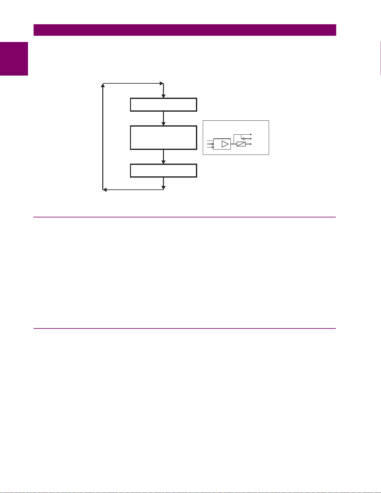
c) UR SCAN OPERATION
The UR-series devices operate in a cyclic scan fashion. The dev ice reads the inputs into an input status table, solves the
1
logic program (FlexLogic™ equation), and then sets each output to the appropriate state in an output status table. Any
resulting task execution is priority interrupt-driven.
Figure 1–3: UR-SERIES SCAN OPERATION
1.2.3 SOFTWARE ARCHITECTURE
The firmware (software embedded in the relay) is designed in functional modules wh ich can be installed in any relay as
required. This is achieved with object-oriented design and programming (OOD/OOP) techniques.
Object-oriented techniques involve the use of objects and classes. An object is defined as “a logical entity that contains
both data and code that manipulates that data”. A class is the generalized form of similar objects. By using this concept,
one can create a protection class with the protection elements as objects of the class, such as time overcurrent, instantaneous overcurrent, current differential, undervoltage, overvoltage, underfrequency, and distance. These objects represent
completely self-contained software modules. The same object-class concept can be used for metering, input/output control,
hmi, communications, or any functional entity in the system.
Employing OOD/OOP in the software architecture of the G60 achieves the same features as the hardware architecture:
modularity, scalability, and flexibility. The application software for any UR-series device (for example, feeder protection,
transformer protection, distance protection) is constructed by combining o b j ects from the various functionality classes. This
results in a common look and feel across the entire family of UR-series platform-based applications.
1.2.4 IMPORTANT CONCEPTS
As described above, the architecture of the UR-series relays differ from previous devices. To achieve a general understanding of this device, some sections of Chapter 5 are quite helpful. The most important functions of the relay are contained in
“elements”. A description of the UR-series elements can be found in the Introduction to elements section in chapter 5.
Examples of simple elements, and some of the organization of this manual, can be found in the Control elements section of
chapter 5. An explanation of the use of inputs from CT s and VTs is in the Introduction to AC sources section in chapter 5. A
description of how digital signals are used and routed within the relay is contained in the Introduction to FlexLogic™ section
in chapter 5.
1-4 G60 Generator Protection System GE Multilin
Page 17

1 GETTING STARTED 1.3 ENERVISTA UR SETUP SOFTWARE
1.3ENERVISTA UR SETUP SOFTWARE 1.3.1 PC REQUIREMENTS
The faceplate keypad and display or the EnerVista UR Setup software interface can be used to communicate with the relay .
The EnerVista UR Setup software interface is the preferred method to edit settings and view actual values because the PC
monitor can display more information in a simple comprehensible format.
The following minimum requirements must be met for the EnerVista UR Setup software to properly operate on a PC.
• Pentium class or higher processor (Pentium II 300 MHz or higher recommended)
• Windows 95, 98, 98SE, ME, NT 4.0 (Service Pack 4 or higher), 2000, XP
• Internet Explorer 4.0 or higher
• 128 MB of RAM (256 MB recommended)
• 200 MB of available space on system drive and 200 MB of available space on installation drive
• Video capable of displaying 800 x 600 or higher in high-color mode (16-bit color)
• RS232 and/or Ethernet port for communications to the relay
The following qualified modems have been tested to be compliant with the G60 and the EnerVista UR Setup software.
• US Robotics external 56K FaxModem 5686
• US Robotics external Sportster 56K X2
• PCTEL 2304WT V.92 MDC internal modem
1.3.2 INSTALLATION
After ensuring the minimum requirements for using EnerVista UR Setup are met (see previous section), use the following
procedure to install the EnerVista UR Setup from the enclosed GE EnerVista CD.
1. Insert the GE EnerVista CD into your CD-ROM drive.
2. Click the Install Now button and follow the installation instructions to install the no-charge EnerVista software.
3. When installation is complete, start the EnerVista Launchpad application.
4. Click the IED Setup section of the Launch Pad window.
1
GE Multilin G60 Generator Protection System 1-5
Page 18
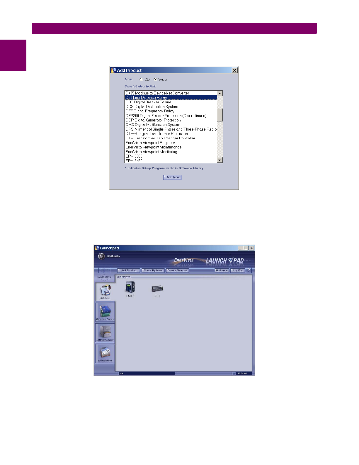
1.3 ENERVISTA UR SETUP SOFTWARE 1 GETTING STARTED
5. In the EnerVista Launch Pad window, click the Add Product button and select the “G60 Generator Protec tion Syste m”
1
from the Install Software window as shown below. Select the “Web” option to ensure the most recent software release,
or select “CD” if you do not have a web connection, then click the Add Now button to list software items for the G60.
6. EnerVista Launchpad will obtain the software from the Web or CD and automatically start the installation program.
7. Select the complete path, including the new directory name, where the EnerVista UR Setup will be installed.
8. Click on Next to begin the installation. The files will be installed in the directory indicated and the installation program
will automatically create icons and add EnerVista UR Setup to the Windows start menu.
9. Click Finish to end the installation. The UR-series device will be added to the list of installed IEDs in the EnerVista
Launchpad window, as shown below.
1-6 G60 Generator Protection System GE Multilin
Page 19

1 GETTING STARTED 1.3 ENERVISTA UR SETUP SOFTWARE
1.3.3 CONFIGURING THE G60 FOR SOFTWARE ACCESS
a) OVERVIEW
The user can connect remotely to the G60 through the rear RS485 port or the rear Ethernet port with a PC running the
EnerVista UR Setup software. The G60 can also be accessed locally with a laptop computer through the front panel RS232
port or the rear Ethernet port using the Quick Connect feature.
• To configure th e G60 for remote access via the rear RS485 port(s), refer to the Configuri ng Serial Communications
section.
• To configure the G6 0 for remote access via the rear Ethernet po rt, refer to the Configuring Ethernet Communicati ons
section. An Ethernet module must be specified at the time of ordering.
• To configure the G60 for local access with a laptop through either the front RS232 port or rear Ethernet port, refer to
the Using the Quick Connect Feature secti on. An Ethernet modul e must be specified at the time of or dering for Ethernet communications.
b) CONFIGURING SERIAL COMMUNICATIONS
Before starting, verify that the serial cable is properly connected to the RS485 terminals on the back of the device. T he
faceplate RS232 port is intended for local use and is not described in this section; see the Using the Quick Connect Feature
section for details on configuring the RS232 port.
A GE Multilin F485 converter (or compatible RS232-to-RS485 converter) is wi ll be required. Refer to th e F485 instruction
manual for additional details.
1. Verify that the latest version of the EnerVista UR Setup software is installed (available from the GE EnerVista CD or
online from http://www.GEmultilin.com
2. Select the “UR” device from the EnerVista Launchpad to start EnerVista UR Setup.
3. Click the Device Setup button to open the Device Setup window and click the Add Site button to define a new site.
4. Enter the desired site name in the “Site Name” field. If desired, a short description of site can also be entere d along
with the display order of devices defined for the site. In this example, we will use “Location 1” a s the site name. Click
the OK button when complete.
5. The new site will appear in the upper-left list in the EnerVista UR Setup window. Click the Device Setup butto n then
select the new site to re-open the Device Setup window.
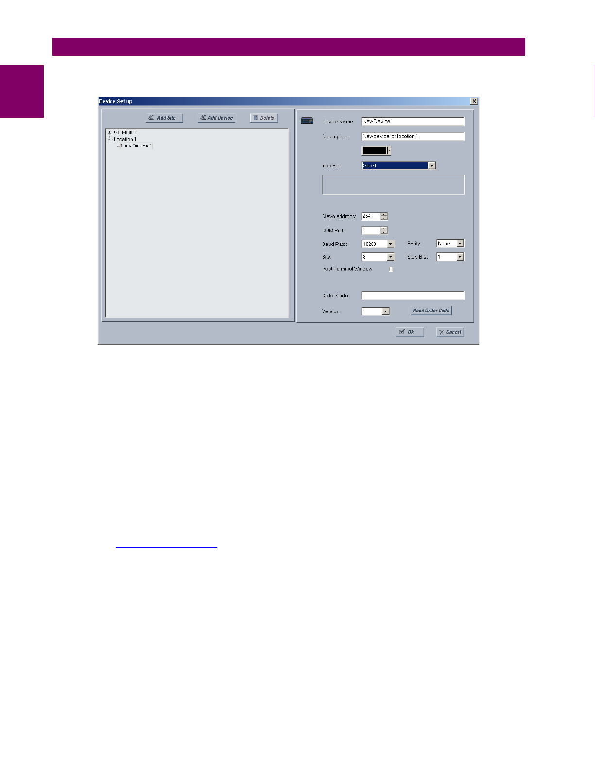
6. Click the Add Device button to define the new device.
7. Enter the desired name in the “Device Name” field and a description (optional) of the site.
). See the Software Installation section for installation details.
1
GE Multilin G60 Generator Protection System 1-7
Page 20
1.3 ENERVISTA UR SETUP SOFTWARE 1 GETTING STARTED
8. Select “Serial” from the Interface drop-down list. This will display a numbe r of interface parameters that must be
entered for proper serial communications.
1
Figure 1–4: CONFIGURING SERIAL COMMUNICATIONS
9. Enter the relay slave address, COM port, baud rate, and parity settings from the
MUNICATIONS ÖØ SERIAL PORTS menu in their respective fields.
10. Click the Read Order Code button to connect to the G60 device and upload the order code. If an communica tions
error occurs, ensure that the EnerVista UR Setup serial communications values entered in the previous step correspond to the relay setting values.
11. Click “OK” when the relay order code has been received. The new device will be added to the Site List window (or
Online window) located in the top left corner of the main EnerVista UR Setup window.
The Site Device has now been configured for RS232 communications. Pro ceed to the Connecting to the G60 section to
begin communications.
c) CONFIGURING ETHERNET COMMUNICATIONS
Before starting, verify that the Ethernet network cable is properly connected to the Ethernet port on the back of the relay. To
setup the relay for Ethernet communications, it will be necessary to define a Site, then add the relay as a Device at that site.
1. Verify that the latest version of the EnerVista UR Setup software is installed (available from the GE EnerVista CD or
online from http://www.GEmultilin.com
2. Select the “UR” device from the EnerVista Launchpad to start EnerVista UR Setup.
3. Click the Device Setup button to open the Device Setup window, then click the Add Site button to define a new site.
4. Enter the desired site name in the “Site Name” field. If desired, a short description of site can also be entered along
with the display order of devices defined for the site. In this example, we will use “Location 2” a s the site name. Click
the OK button when complete.
5. The new site will appear in the upper-left list in the EnerVista UR Setup window. Click the Device Setup butto n then
select the new site to re-open the Device Setup window.
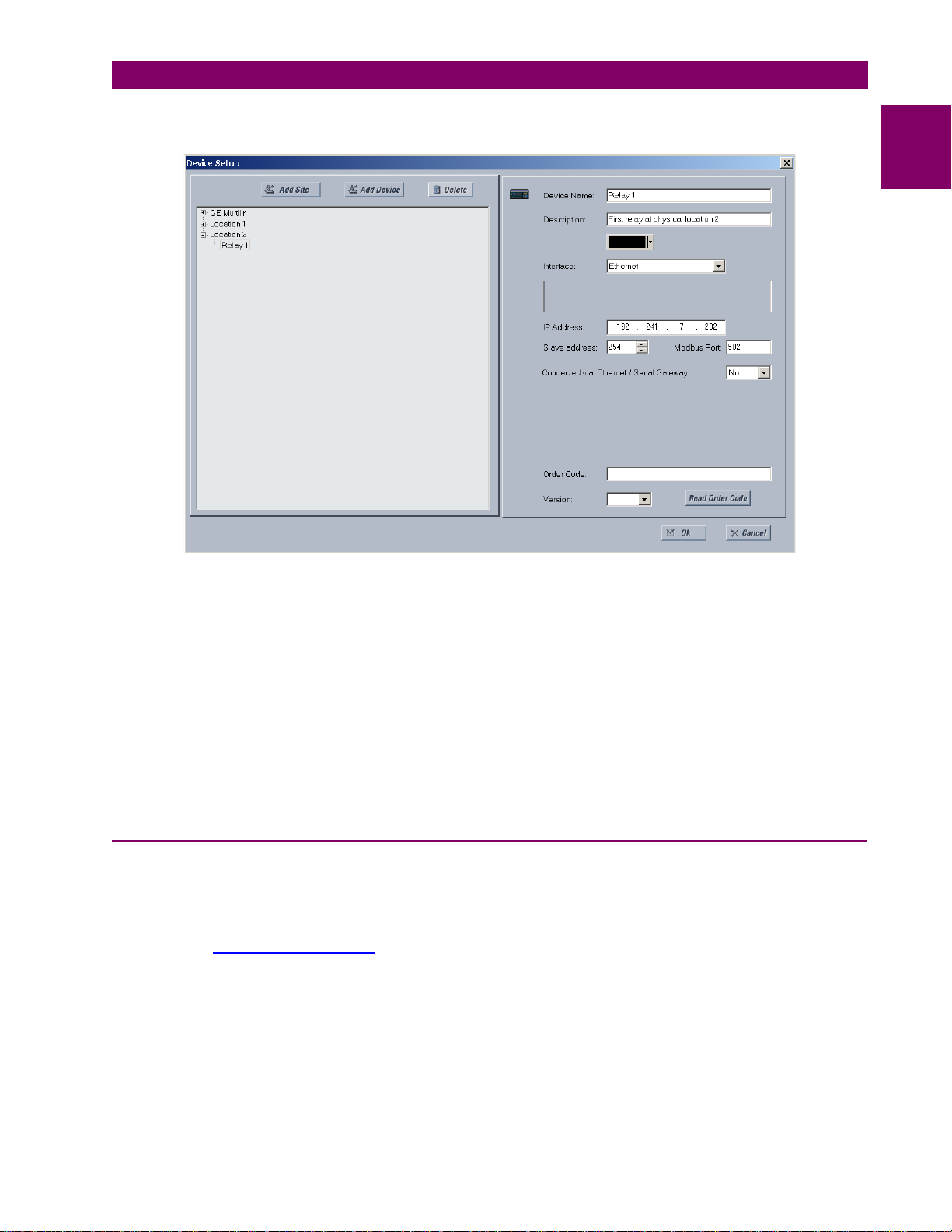
6. Click the Add Device button to define the new device.
7. Enter the desired name in the “Device Name” field and a description (optional) of the site.
). See the Software Installation section for installation details.
SETTINGS Ö PRODUCT SETUP ÖØ COM-
1-8 G60 Generator Protection System GE Multilin
Page 21
1 GETTING STARTED 1.3 ENERVISTA UR SETUP SOFTWARE
8. Select “Ethernet” from the Interface drop-down list. This will display a number of interface parameters that must be
entered for proper Ethernet functionality.
1
Figure 1–5: CONFIGURING ETHERNET COMMUNICATIONS
9. Enter the relay IP address specified in the
ADDRESS) in the “IP Address” field.
10. Enter the relay sl ave address and Modbus port address values fro m the respective settings in the SETTINGS Ö PROD-
UCT SETUP ÖØ COMMUNICATIONS ÖØ MODBUS PROTOCOL menu.
11. Click the Read Order Code button to connect to the G60 device and upload the order code. If an communications
error occurs, ensure that the three EnerVista UR Setup values entered in the previous steps correspond to the relay
setting values.
12. Click OK when the relay order code has been received. The new device will be added to the Site L ist window (or
Online window) located in the top left corner of the main EnerVista UR Setup window.
The Site Device has now been configured for Ethernet communications. Proceed to the Connecting to the G60 section to
begin communications.
a) USING QUICK CONNECT VIA THE FRONT PANEL RS232 PORT
Before starting, verify that the serial cable is properly connected from the laptop computer to the front panel RS232 port
with a straight-through 9-pin to 9-pin RS232 cable.
1. Verify that the latest version of the EnerVista UR Setup software is installed (available from the GE EnerVista CD or
online from http://www.GEmultilin.com
2. Select the “UR” device from the EnerVista Launchpad to start EnerVista UR Setup.
SETTINGS Ö P RODUCT SETUP ÖØ COMMUNICATIONS ÖØ NETWORK Ö IP
1.3.4 USING THE QUICK CONNECT FEATURE
). See the Software Installation section for installation details.
GE Multilin G60 Generator Protection System 1-9
Page 22
1.3 ENERVISTA UR SETUP SOFTWARE 1 GETTING STARTED
842799A1.CDR
END 1 END 2
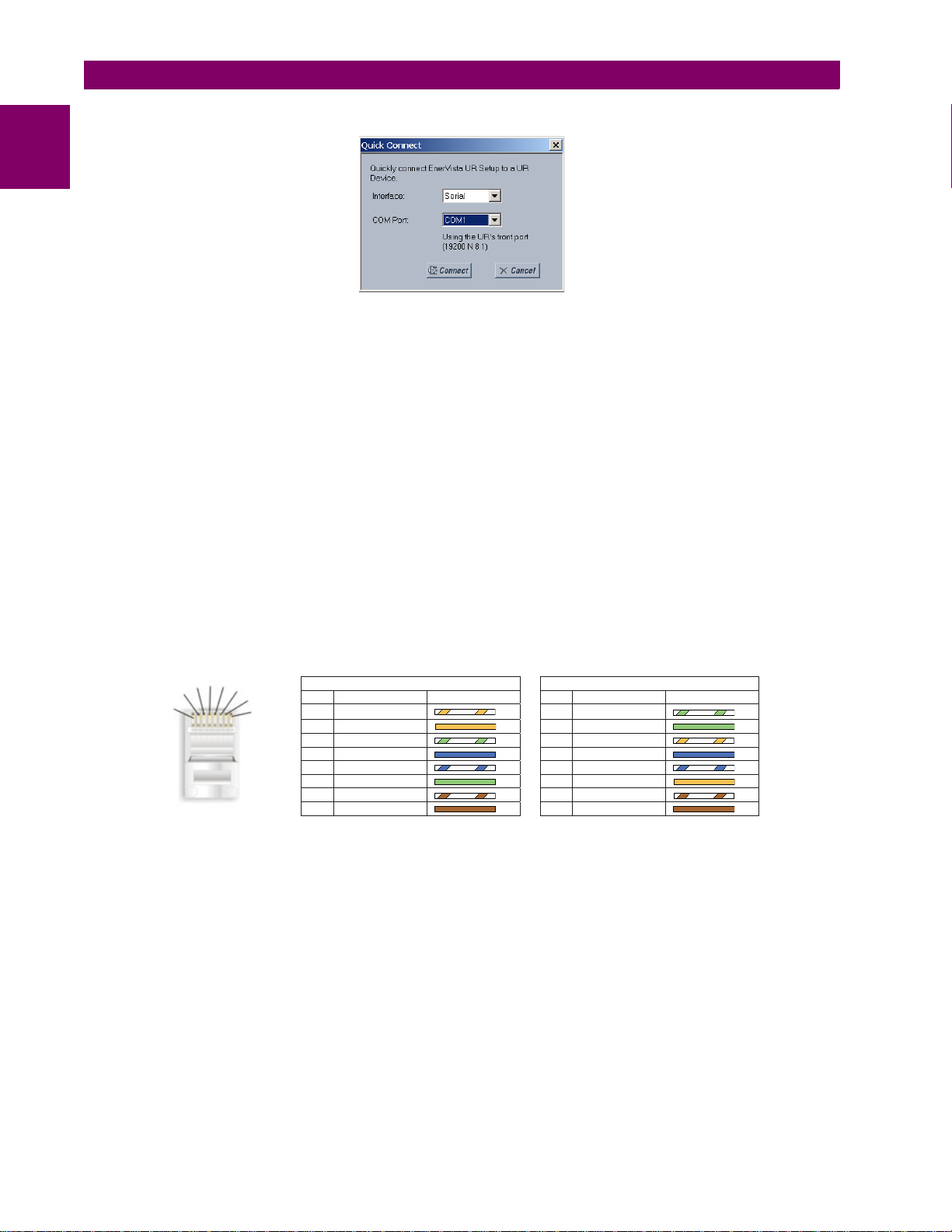
Pin Wire color Diagram Pin Wire color Diagram
1 White/orange 1 White/green
2 Orange 2 Green
3 White/green 3 White/orange
4 Blue 4 Blue
5 White/blue 5 White/blue
6 Green 6 Orange
7 White/brown 7 White/brown
8 Brown 8 Brown
1
2
3
4
5
6
7
8
3. Click the Quick Connect button to open the Quick Connect dialog box.
1
4. Select the Serial interface and the correct COM Port, then click Connect.
5. The EnerVista UR Setup software will create a site named “Quick Connect” with a corresponding device also named
“Quick Connect” and display them on the upper-left corner of the screen. Expand the sections to vie w data directly
from the G60 device.
Each time the EnerVista UR Setup software is initialized, click the Quick Connect button to establish direct communications to the G60. This ensures that configuration of the EnerVista UR Setup software matches the G60 model number.
b) USING QUICK CONNECT VIA THE REAR ETHERNET PORTS
To use the Quick Connect feature to access the G60 from a laptop through Ethernet, first assign an IP address to the relay
from the front panel keyboard.
1. Press the MENU key until the SETTINGS menu is displayed.
2. Navigate to the
3. Enter an IP address of “1.1.1.1” and select the ENTER key to save the value.
4. In the same menu, select the
5. Enter a subnet IP address of “255.0.0.0” and press the ENTER key to save the value.
Next, use an Ethernet cross-over cable to connect the laptop to the rear Ethernet port. The pinout for an Ethernet crossover cable is shown below.
SETTINGS Ö PRODUCT SETUP ÖØ COMMUNICATIONS ÖØ NETWORK Ö IP ADDRESS setting.
SUBNET IP MASK setting.
Figure 1–6: ETHERNET CROSS-OVER CABLE PIN LAYOUT
Now, assign the laptop computer an IP address compatible with the relay’s IP address.
1-10 G60 Generator Protection System GE Multilin
Page 23
1 GETTING STARTED 1.3 ENERVISTA UR SETUP SOFTWARE
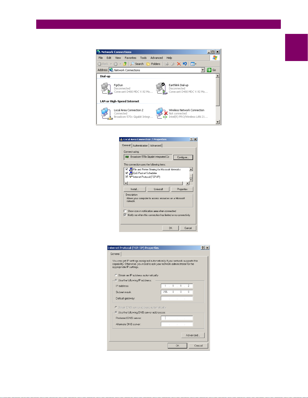
1. From the Windows desktop, right-click the My Network Places icon an d select Properties to open the network con-
nections window.
2. Right-click the Local Area Connection icon and select Properties.
1
3. Select the Internet Protocol (TCP/IP) item from the list provided and click the Properties button.
4. Click on the “Use the following IP address” box.
GE Multilin G60 Generator Protection System 1-11
Page 24

1.3 ENERVISTA UR SETUP SOFTWARE 1 GETTING STARTED
5. Enter an IP address with the first three numbers the same as the IP address of the G60 relay and the last number different (in this example, 1.1.1.2).
1
6. Enter a subnet mask equal to the one set in the G60 (in this example, 255.0.0.0).
7. Click OK to save the values.
Before continuing, it will be necessary to test the Ethernet connection.
1. Open a Windows console window by selecting Start > Run from the Windows Start menu and typing “cmd”.
2. Type the following command:
C:\WINNT>ping 1.1.1.1
3. If the connection is successful, the system will return four replies as follows:
Pinging 1.1.1.1 with 32 bytes of data:
Reply from 1.1.1.1: bytes=32 time<10ms TTL=255
Reply from 1.1.1.1: bytes=32 time<10ms TTL=255
Reply from 1.1.1.1: bytes=32 time<10ms TTL=255
Reply from 1.1.1.1: bytes=32 time<10ms TTL=255
Ping statistics for 1.1.1.1:
Packets: Sent = 4, Received = 4, Lost = 0 (0% loss),
Approximate round trip time in milli-sec ond s:
Minimum = 0ms, Maximum = 0ms, Average = 0 ms
4. Note that the values for time and TTL will vary depending on local network configuration.
If the following sequence of messages appears when entering the C:\WINNT>ping 1.1.1.1 command:
Pinging 1.1.1.1 with 32 bytes of data:
Request timed out.
Request timed out.
Request timed out.
Request timed out.
Ping statistics for 1.1.1.1:
Packets: Sent = 4, Received = 0, Lost = 4 (100% loss),
Approximate round trip time in milli-sec ond s:
Minimum = 0ms, Maximum = 0ms, Average = 0 ms
Pinging 1.1.1.1 with 32 bytes of data:
Verify the physical connection between the G60 and the laptop computer, and double-check the programmed IP address in
the PRODUCT SETUP ÖØ COMMUNICATIONS ÖØ NETWORK Ö IP ADDRESS setting, then repeat step 2 in the above procedure.
If the following sequence of messages appears when entering the C:\WINNT>ping 1.1.1.1 command:
Pinging 1.1.1.1 with 32 bytes of data:
Hardware error.
Hardware error.
Hardware error.
Hardware error.
Ping statistics for 1.1.1.1:
Packets: Sent = 4, Received = 0, Lost = 4 (100% loss),
Approximate round trip time in milli-sec ond s:
Minimum = 0ms, Maximum = 0ms, Average = 0 ms
Pinging 1.1.1.1 with 32 bytes of data:
Verify the physical connection between the G60 and the laptop computer, and double-check the programmed IP address in
PRODUCT SETUP ÖØ COMMUNICATIONS ÖØ NETWORK Ö IP ADDRESS setting, then repeat step 2 in the above procedure.
the
If the following sequence of messages appears when entering the
C:\WINNT>ping 1.1.1.1 command:
1-12 G60 Generator Protection System GE Multilin
Page 25
1 GETTING STARTED 1.3 ENERVISTA UR SETUP SOFTWARE
Pinging 1.1.1.1 with 32 bytes of data:
Destination host unreachable.
Destination host unreachable.
Destination host unreachable.
Destination host unreachable.
Ping statistics for 1.1.1.1:
Packets: Sent = 4, Received = 0, Lost = 4 (100% loss),
Approximate round trip time in milli-sec ond s:
Minimum = 0ms, Maximum = 0ms, Average = 0 ms
Pinging 1.1.1.1 with 32 bytes of data:
Verify the IP address is programmed in the local PC by entering the ipconfig command in the command window.
C:\WINNT>ipconfig
Windows 2000 IP Configuration
Ethernet adapter <F4FE223E-5EB6-4 BF B-9 E3 4-1 BD 7B E7F 59 FF> :
Connection-specific DNS suffix. . :
IP Address. . . . . . . . . . . . : 0.0.0.0
Subnet Mask . . . . . . . . . . . : 0.0.0.0
Default Gateway . . . . . . . . . :
Ethernet adapter Local Area Connection:
Connection-specific DNS suffix . :
IP Address. . . . . . . . . . . . : 1.1.1.2
Subnet Mask . . . . . . . . . . . : 255.0.0.0
Default Gateway . . . . . . . . . :
C:\WINNT>
It may be necessary to restart the laptop for the change in IP address to take effect (Windows 98 or NT).
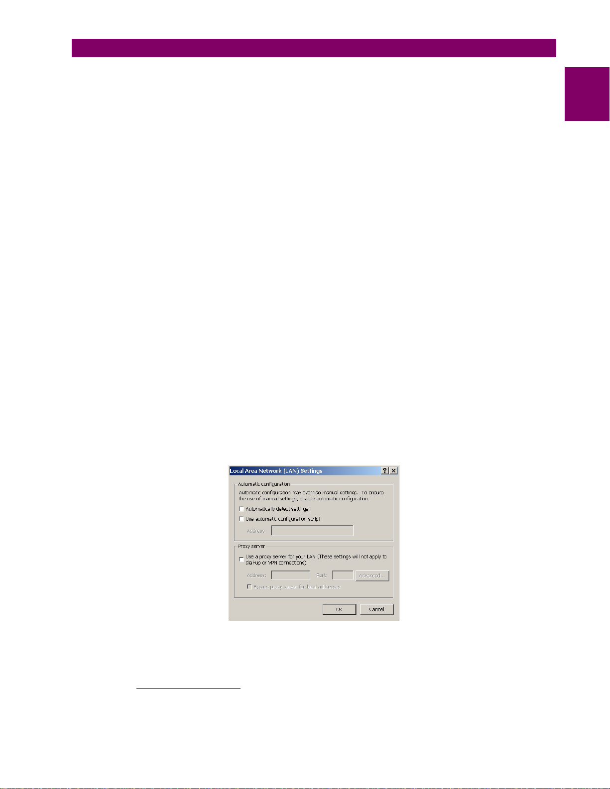
Before using the Quick Connect feature through the Ethernet port, i t is necessary to di sable any configu red proxy settings
in Internet Explorer.
1. Start the Internet Explorer software.
2. Select the Tools > Internet Options menu item and click on Connections tab.
3. Click on the LAN Settings button to open the following window.
1
4. Ensure that the “Use a proxy server for your LAN” box is not checked.
If this computer is used to connect to the Internet, re-enable any proxy server settings after the laptop has been d iscon-
nected from the G60 relay.
1. Verify that the latest version of the EnerVista UR Setup software is installed (available from the GE enerVista CD or
online from http://www.GEmultilin.com). See the Software Installation section for installation details.
2. Start the Internet Explorer software.
GE Multilin G60 Generator Protection System 1-13
Page 26
1.3 ENERVISTA UR SETUP SOFTWARE 1 GETTING STARTED
3. Select the “UR” device from the EnerVista Launchpad to start EnerVista UR Setup.
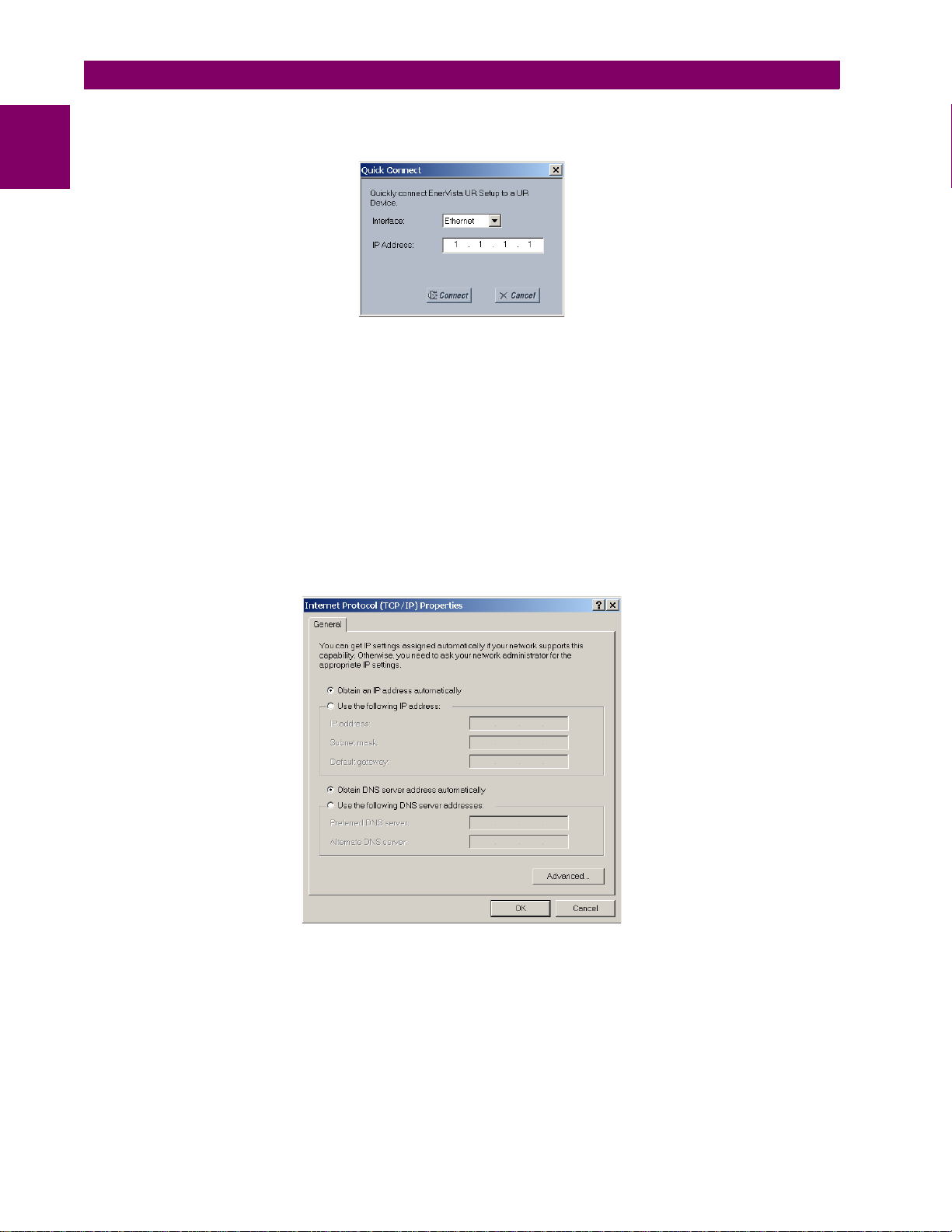
4. Click the Quick Connect button to open the Quick Connect dialog box.
1
5. Select the Ethernet interface and enter the IP address assigned to the G60, then click Connect.
6. The EnerVista UR Setup software will create a site named “Quick Connect” with a corresponding device also named
“Quick Connect” and display them on the upper-left corner of the screen. Expand the sections to vie w data directly
from the G60 device.
Each time the EnerVista UR Setup software is initialized, click the Quick Connect button to establish direct communications to the G60. This ensures that configuration of the EnerVista UR Setup software matches the G60 model number.
When direct communications with the G60 via Ethernet is complete, make the following changes:
1. From the Windows desktop, right-click the My Network Places icon an d select Properties to open the network connections window.
2. Right-click the Local Area Connection icon and select the Properties item.
3. Select the Internet Protocol (TCP/IP) item from the list provided and click the Properties button.
4. Set the computer to “Obtain a relay address automatically” as shown below.
If this computer is used to connect to the Internet, re-enable any proxy server settings after the laptop has been disconnected from the G60 relay.
AUTOMATIC DISCOVERY OF ETHERNET DEVICES
The EnerVista UR Setup software can automatically discover and communicate to all UR-series IEDs located on an Ethernet network.
Using the Quick Connect feature, a single click of the mouse will trigger the software to automatically detect any UR-series
relays located on the network. The EnerVista UR Setup software will then proceed to configure all settin gs and orde r code
options in the Device Setup menu, for the purpose of communicating to mu ltiple relays. This feature allows the user to
identify and interrogate, in seconds, all UR-series devices in a particular location.
1-14 G60 Generator Protection System GE Multilin
Page 27
1 GETTING STARTED 1.3 ENERVISTA UR SETUP SOFTWARE
842743A3.CDR
Communications status indicators:
Green = OK
Red = No communications
UR icon = report is open
Quick action hot links
Expand the site list by double-clicking
or selecting the +/– box.
NOTE
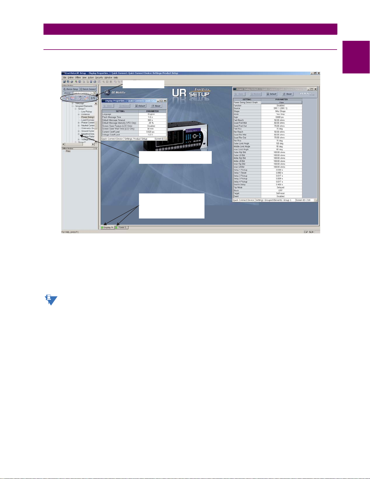
1.3.5 CONNECTING TO THE G60 RELAY
1. Open the Display Properties window through the Site List tree as shown below:
1
2. The Display Properties window will open with a status indicator on the lower left of the EnerVista UR Setup window.
3. If the status indicator is red, verify that the Ethernet network cable is properly connected to the Eth ernet port on the
back of the relay and that the relay has been properly setup for communications (steps A and B earlier).
If a relay icon appears in place of the status indicator, than a report (such as an oscillography or event record) is open.
Close the report to re-display the green status indicator.
4. The Display Properties settings can now be edited, printed, or changed according to user specifications.
Refer to chapter 4 in this manual and the EnerVista UR Setup Help File for more information about the
using the EnerVista UR Setup software interface.
QUICK ACTION HOT LINKS
The EnerVista UR Setup software has several new quick action buttons that provide users with instant access to several
functions that are often performed when using G60 relays. From the online window, users can select which relay to interrogate from a pull-down window, then click on the button for the action they wish to perform. The following quick action functions are available:
• View the G60 event record.
• View the last recorded oscillography record.
• View the status of all G60 inputs and outputs.
• View all of the G60 metering values.
• View the G60 protection summary.
GE Multilin G60 Generator Protection System 1-15
Page 28
1.4 UR HARDWARE 1 GETTING STARTED
1.4UR HARDWARE 1.4.1 MOUNTING AND WIRING
1
Please refer to Chapter 3: Hardware for detailed mounting and wiring instructions. Review all WARNINGS and CAUTIONS
carefully.
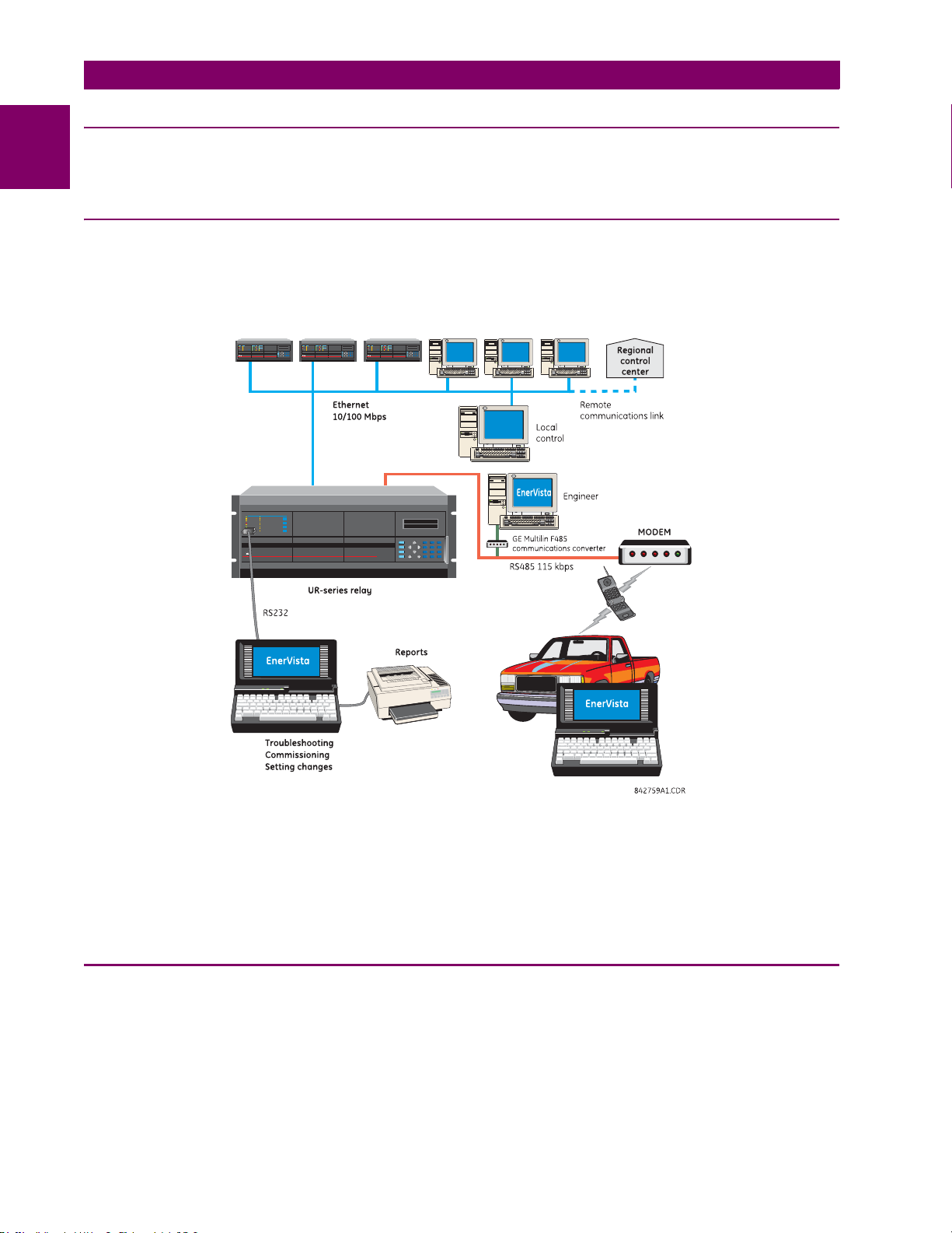
1.4.2 COMMUNICATIONS
The EnerVista UR Setup software communicates to the relay via the faceplate RS232 port or the rear panel RS485 / Ethernet ports. To communicate via the faceplate RS232 port, a standard straight-through serial cable is used. The DB-9 male
end is connected to the relay and the DB-9 or DB-25 female end is connected to the PC COM1 or COM2 port as described
in the CPU communications ports section of chapter 3.
Figure 1–7: RELAY COMMUNICATIONS OPTIONS
To communicate through the G60 rear RS485 port fro m a PC RS232 port, the GE Multilin RS232/RS485 converter bo x is
required. This device (catalog number F485) connects to the computer using a “straight-through” serial cable. A shield ed
twisted-pair (20, 22, or 24 AWG) connects the F485 converter to the G60 rear communications port. The converter terminals (+, –, GND) are connected to the G60 communication module (+, –, COM) terminals. Refer to the CPU communica-
tions ports section in chapter 3 for option details. The line should be terminated wi th an R-C network (that is, 12 0 Ω, 1 nF)
as described in the chapter 3.
1.4.3 FACEPLATE DISPLAY
All messages are displayed on a 2 × 20 backlit liquid crystal display (LCD) to make them vi sible under poor l ighting conditions. Messages are descriptive and should not re quire the aid of an instruction manual for decip hering. While the keypad
and display are not actively being used, th e display will default to user-defined messages. Any high priority event driven
message will automatically override the default message and appear on the display.
1-16 G60 Generator Protection System GE Multilin
Page 29
1 GETTING STARTED 1.5 USING THE RELAY
1.5USING THE RELAY 1.5.1 FACEPLATE KEYPAD
Display messages are organized into pages under the following headings: actual values, settings, comma nds, and targets.
The MENU key navigates through these pages. Each heading page is broken down further into logical subgroups.
The MESSAGE keys navigate through the subgroups. The VALUE keys scroll increment or decrement numerical setting
values when in programming mode. These keys also scroll through alphanumeric valu es in the text edit mode. Alternatively, values may also be entered with the numeric keypad.
The decimal key initiates and advance to the next character in text edit mode or enters a decimal point. The HELP key may
be pressed at any time for context sensitive help messages. The ENTER key stores altered setting values.
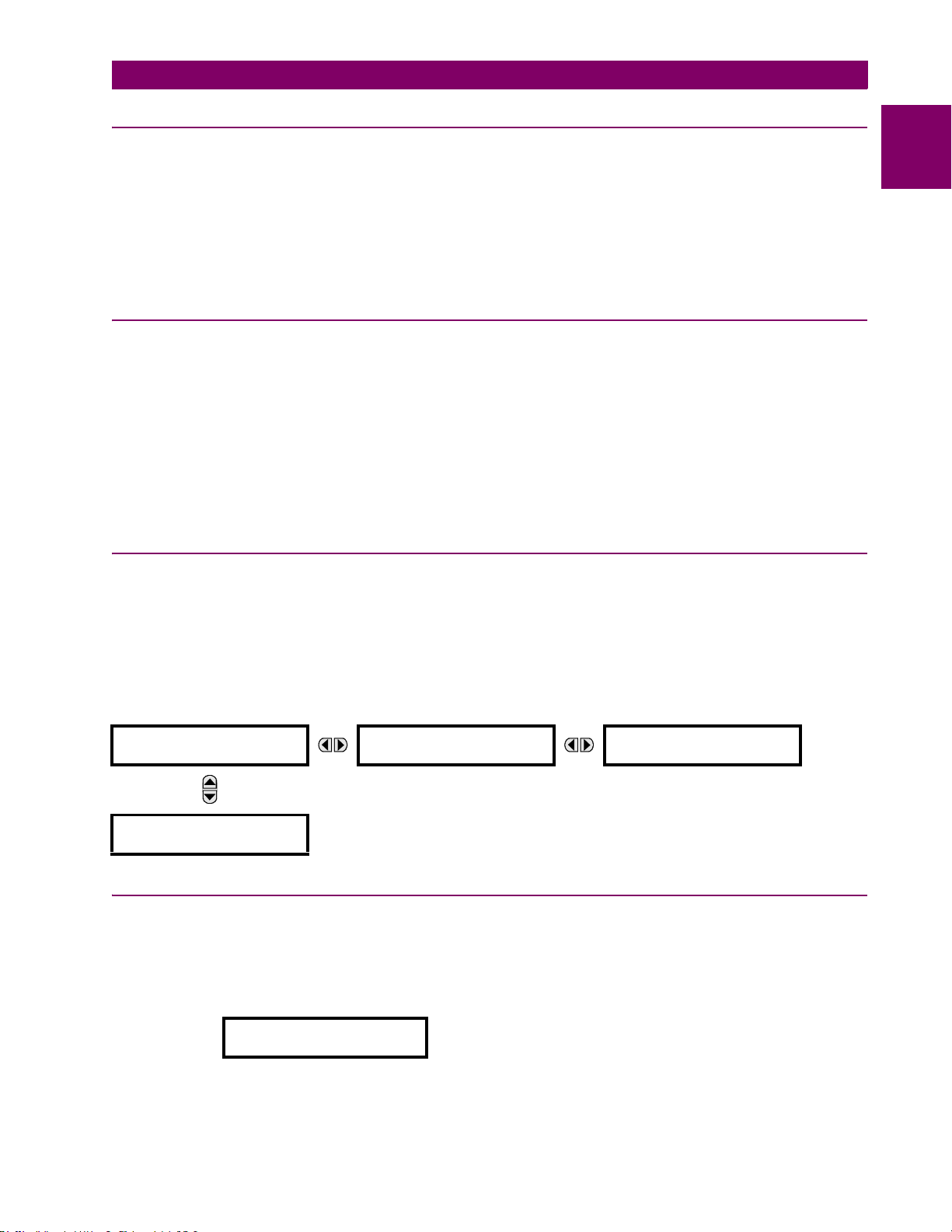
1.5.2 MENU NAVIGATION
Press the MENU key to select the desired header display page (top-level menu). The header title appears momentarily followed by a header display page menu item. Each press of the MENU key advances through the following mai n heading
pages:
• Actual values.
• Settings.
• Commands.
• Targets.
• User displays (when enabled).
1.5.3 MENU HIERARCHY
The setting and actual value messages are arranged hierarchically. The header display pages are indicated by double
scroll bar characters (), while sub-header pages are indicated by single scroll bar characters (). The header display
pages represent the highest level of the hierarchy and the sub-header display pages fall below this leve l. The MESSAGE
UP and DOWN keys move within a group of headers, sub-headers, setting values, or actual values. Continua lly pressing
the MESSAGE RIGHT key from a header display displays specific information for the header category. Conversely, continually pressing the MESSAGE LEFT key from a setting value or actual value display returns to the header display.
1
HIGHEST LEVEL LOWEST LEVEL (SETTING VALUE)
SETTINGS
PRODUCT SETUP
SETTINGS
SYSTEM SETUP
The relay is defaulted to the “Not Programme d” state when it leaves the factory. This safeguards against the installation of
a relay whose settings have not been entered. When powered up successfu lly, the Trouble LED will be on and the In Service LED off. The relay in the “Not Programmed” state will block signaling of any output relay. These conditions will remain
until the relay is explicitly put in the “Programmed” state.
Select the menu message
RELAY SETTINGS:
Not Programmed
SETTINGS Ö PRODUCT SETUP ÖØ INST ALLATION Ö RELAY SETTINGS
PASSWORD
SECURITY
ACCESS LEVEL:
Restricted
1.5.4 RELAY ACTIVATION
GE Multilin G60 Generator Protection System 1-17
Page 30

1.5 USING THE RELAY 1 GETTING STARTED
NOTE
To put the relay in the “Programmed” state, press either of the VALUE keys once and then press ENTER. The faceplate
Trouble LED will turn off and the In Service LED will turn on. The settings for the relay can be programmed manually (refer
1
to Chapter 5) via the faceplate keypad or remotely (refer to the EnerVista UR Setup help file) via the Ene rVista UR Setup
software interface.
1.5.5 RELAY PASSWORDS
It is recommended that passwords be set up for each security level and assigned to specific personnel. There are two user
password security access levels, COMMAND and SETTING:
1. COMMAND
The COMMAND access level restricts the user from making any settings changes, but allows the user to perform the following operations:
• change state of virtual inputs
• clear event records
• clear oscillography records
• operate user-programmable pushbuttons
2. SETTING
The SETTING access level allows the user to make any changes to any of the setting values.
Refer to the Changing Settings section in Chapter 4 for co mplete instructions on setting u p security level
passwords.
1.5.6 FLEXLOGIC™ CUSTOMIZATION
FlexLogic™ equation editing is required for setting up user-defined logic for customizing the relay operations. See the FlexLogic™ section in Chapter 5 for additional details.
1-18 G60 Generator Protection System GE Multilin
Page 31

1 GETTING STARTED 1.5 USING THE RELAY
1.5.7 COMMISSIONING
The G60 requires a minimum amount of maintenance when it is commissioned into service. Since the G60 is a microprocessor-based relay, its characteristics do not change over time. As such, no further functional tests are required.
Furthermore, the G60 performs a number of continual self-tests and takes the necessary action in case of any major errors
(see the Relay Self-tests section in chapter 7 for details). However , it is recommended that G60 maintenance be scheduled
with other system maintenance. This maintenance may involve the in-service, out-of-service, or unscheduled maintenance.
In-service maintenance:
1. Visual verification of the analog values integrity such as voltage and current (in comparison to other devices on the cor-
responding system).
2. Visual verification of active alarms, relay display messages, and LED indications.
3. LED test.
4. Visual inspection for any damage, corrosion, dust, or loose wires.
5. Event recorder file download with further events analysis.
Out-of-service maintenance:
1. Check wiring connections for firmness.
2. Analog values (currents, voltages, RTDs, analog inputs) injection test and metering accuracy verification. Calibrated
test equipment is required.
3. Protection elements setting verification (analog values injection or visual verification of setting file entries against relay
settings schedule).
4. Contact inputs and outputs verification. This test can be conducted by direct change of state forcing or as part of the
system functional testing.
5. Visual inspection for any damage, corrosion, or dust.
6. Event recorder file download with further events analysis.
7. LED Test and pushbutton continuity check.
Unscheduled maintenance such as during a disturbance causing system interruption:
1. View the event recorder and oscillography or fault report for correct operation of inputs, outputs, and elements.
If it is concluded that the relay or one of its modules is of concern, contact GE Multilin for prompt service.
1
GE Multilin G60 Generator Protection System 1-19
Page 32

1
1.5 USING THE RELAY 1 GETTING STARTED
1-20 G60 Generator Protection System GE Multilin
Page 33

2 PRODUCT DESCRIPTION 2.1 INTRODUCTION
2 PRODUCT DESCRIPTION 2.1INTRODUCTION 2.1.1 OVERVIEW
The G60 Generator Protection System is a microprocessor based rela y that provides protection, monitoring, control, and
recording functions for AC generators driven by steam, gas, or hydraulic turbine. Current, voltage and frequency protection
are provided along with fault diagnostics.
Voltage, current, and power metering is built into the relay as a standard feature. Current parameters are available as total
waveform RMS magnitude, or as fundamental frequency only RMS magnitude and angle (phasor).
Diagnostic features include an event recorder capable of storing 1024 time-tagged events, oscillography capable of storing
up to 64 records with programmable trigger, content and sampling rate, and data logger acquisition of up to 16 channels,
with programmable content and sampling rate. The internal clock us ed for time-tagging can be synch ronized with an IRIGB signal or via the SNTP protocol over the Ethernet port. This preci se time stamping allows the sequence o f events to be
determined throughout the system. Events can also be programmed (via FlexLogic™ equations) to trigger oscillography
data capture which may be set to record the measured parameters before and after the event for viewing on a personal
computer (PC). These tools significantly reduce troubleshooting time and simplify report generation in the even t of a system fault.
A faceplate RS232 port may be used to connect to a PC for the programming of settings and the monitoring of actual values. A variety of communications modules are available. Two rear RS485 ports allow independent access by operating and
engineering staff. All serial ports use the Modbus
®
RTU protocol. The RS485 ports may be connected to system computers
with baud rates up to 115.2 kbps. The RS232 port has a fixed baud rate of 19.2 kbps. Optional commun ications modules
include a 10Base-F Ethernet interface which can be used to provide fast, reliable communications in noisy environments.
Another option provides two 10Base-F fiber optic ports for redundancy. The Ethernet port supports IEC 61850, Modbus
TCP, and TFTP protocols, and allows access to the relay via any standard web browser (G60 web pages). The IEC 608705-104 protocol is supported on the Ethernet port. DNP 3.0 and IEC 60870-5-104 cannot be enabled at the same time.
The G60 IEDs use flash memory technology which allows field upgrading as new features are added. The following Single
line diagram illustrates the relay functionality using ANSI (American National Standards Institute) device numbers.
2
®
/
Table 2–1: ANSI DEVICE NUMBERS AND FUNCTIONS
DEVICE
NUMBER
21P Phase distance backup 51P Phase time overcurrent
24 Volts per hertz 59N Neutral overvoltage
25 Synchrocheck 59P Phase over voltage
27P Phase undervoltage 59X Auxiliary overvoltage
27TN Third harmonic neutral undervoltage 59_2 Negative-sequence overvoltage
27X Auxiliary undervoltage 64TN 100% stator ground
32 Sensitive directional power 67_2 Negative-sequence directional overcurrent
40 Loss of excitation 67N Neutral directional overcurrent
46 Generator unbalance 67P Phase directional overcurrent
49 Thermal overload (RTD) 68/78 Power swing detection
50G Ground instantaneous overcurrent 81A Frequency out-of-band accumulation
50N Neutral instantaneous overcurrent 81O Overfrequency
50P Phase instantaneous overcurrent 81R Rate of change of frequency
50SP Split phase protection 81U Underfrequency
50/27 Accidental energization 87G Restricted ground fault
51G Ground time overcurrent 87S Stator differential
FUNCTION DEVICE
NUMBER
FUNCTION
GE Multilin G60 Generator Protection System 2-1
Page 34

2
830710AA.CDR
50G87G 51G
64TN
51P 51N
46
67P 67N67_2
68 78
24
59P
27P
59_2
25
Metering
Trip
Close
32
50/27
40
59N
81U
81O
27TN
59X27X
G60 Generator Protection System
52
R
87S
50N
81R
50P
21P
G
49
2.1 INTRODUCTION 2 PRODUCT DESCRIPTION
Figure 2–1: SINGLE LINE DIAGRAM
Table 2–2: OTHER DEVICE FUNCTIONS
FUNCTION FUNCTION FUNCTION
Breaker control FlexElements™ (16) Stator differential
Contact inputs (up to 96) Generator unbalance Synchrophasors
Contact outputs (up to 96) IEC 61850 communications (optional) Time synchronization over SNTP
Control pushbuttons Metering: current, voltage, power,
Data logger Trip output
Digital counters (8) Oscillography User-definable displays
Digital elements (48) Modbus communications User-programmable fault reports
frequency
Direct inputs and outputs (32) Modbus user map User-programmable LEDs
Disconnect switches Non-volatile latches User-programmable pushbuttons
DNP 3.0 or IEC 60870-5-104 protocol Non-volatile selector switch User-programmable self-tests
Ethernet Global Data protocol (optional) RTD protection Virtual inputs (64)
Event recorder Remote RTD protection Virtual outputs (96)
FlexLogic™ equations Setting groups (6) VT fuse failure
Transducer inputs and outputs
2-2 G60 Generator Protection System GE Multilin
Page 35

2 PRODUCT DESCRIPTION 2.1 INTRODUCTION
NOTE
2.1.2 ORDERING
a) OVERVIEW
The G60 is available as a 19-inch rack horizontal mount or reduced-size (¾) vertical unit and consists of the following modules: power supply, CPU, CT/VT, digital input and output, transducer input and output, and inter-relay communications.
Each of these modules can be supplied in a number of configurations specified at the time of ordering. The information
required to completely specify the relay is provided in the following tables (see chapter 3 for full details of relay modules).
Order codes are subject to change without notice. Refer to the GE Multilin ordering page at
http://www.GEindustrial.com/multilin/order.htm for the latest details concerning G60 ordering options.
The order code structure is dependent on the mounting option (horizontal or vertical) and the type of CT/VT modules (regular CT/VT modules or the HardFiber modules). The order code options are described in the following sub-sections.
2
GE Multilin G60 Generator Protection System 2-3
Page 36

2.1 INTRODUCTION 2 PRODUCT DESCRIPTION
b) ORDER CODES WITH TRADITIONAL CTS AND VTS
The order codes for the horizontal mount units with traditional CTs and VTs are shown below.
Table 2–3: G60 ORDER CODES (HORIZONTAL UNITS)
BASE UNIT G60 | | | | | | | | | | | Base Unit
CPU E | | | | | | | | | | RS485 and RS485
2
SOFTWARE 00 | | | | | | | | | No Software Options
MOUNT/COATING H | | | | | | | | Horizontal (19” rack)
FACEPLATE/ DISPLAY C | | | | | | | English display
POWER SUPPLY
(redundant supply must
be same type as main supply)
CT/VT MODULES 8F | 8F | | | Standard 4CT/4VT
DIGITAL INPUTS/OUTPUTS XX XX XX XX XX No Module
TRANSDUCER
INPUTS/OUTPUTS
(select a maximum of 3 per unit)
INTER-RELAY
COMMUNICATIONS
(select a maximum of 1 per unit)
G60 - * ** - * * * - F ** - H ** - M ** - P ** - U ** - W/X ** Full Size Horizontal Mount
G | | | | | | | | | | RS485 and multi-mode ST 10Base-F
H | | | | | | | | | | RS485 and multi-mode ST redundant 10Base-F
J | | | | | | | | | | RS485 and multi-mode ST 100Base-FX
K | | | | | | | | | | RS485 and multi-mode ST redundant 100Base-FX
L | | | | | | | | | | RS485 and single mode SC 100Base-FX
M | | | | | | | | | | RS485 and single mode SC redundant 100Base-FX
N | | | | | | | | | | RS485 and 10/100Base-T
P | | | | | | | | | | RS485 and single mode ST 100Base-FX
R | | | | | | | | | | RS485 and single mode ST redundant 100Base-FX
S | | | | | | | | | | RS485 and six-port managed Ethernet switch
01 | | | | | | | | | Ethernet Global Data (EGD); not available for Type E CPUs
03 | | | | | | | | | IEC 61850; not available for Type E CPUs
04 | | | | | | | | | Ethernet Global Data (EGD) and IEC 61850; not available for Type E CPUs
06 | | | | | | | | | Phasor measurement unit (PMU)
07 | | | | | | | | | IEC 61850 and phasor measurement unit (PMU)
A | | | | | | | | Horizontal (19” rack) with harsh environmental coating
D | | | | | | | French display
R | | | | | | | Russian display
A | | | | | | | Chinese display
P | | | | | | | English display with 4 small and 12 large programmable pushbuttons
G | | | | | | | French display with 4 small and 12 large programmable pushbuttons
S | | | | | | | Russian display with 4 small and 12 large programmable pushbuttons
B | | | | | | | Chinese display with 4 small and 12 large programmable pushbuttons
K | | | | | | | Enhanced front panel with English display
M | | | | | | | Enhanced front panel with French display
Q | | | | | | | Enhanced front panel with Russian display
U | | | | | | | Enhanced front panel with Chinese display
L | | | | | | | Enhanced front panel with English display and user-programmable pushbuttons
N | | | | | | | Enhanced front panel with French display and user-programmable pushbuttons
T | | | | | | | Enhanced front panel with Russian display and user-programmable pushbuttons
V | | | | | | | Enhanced front panel with Chinese display and user-programmable pushbuttons
H | | | | | | 125 / 250 V AC/DC power supply
H | | | | | RH 125 / 250 V AC/DC with redundant 125 / 250 V AC/DC power supply
L | | | | | | 24 to 48 V (DC only) power supply
L | | | | | RL 24 to 48 V (DC only) with redundant 24 to 48 V DC power supply
8G | 8G | | | Sensitive Ground 4CT/4VT
8H | 8H | | | Standard 8CT
8J | 8J | | | Sensitive Ground 8CT
8L | 8L | | | Standard 4CT/4VT with enhanced diagnostics
8M | 8M | | | Sensitive Ground 4CT/4VT with enhanced diagnostics
8N | 8N | | | Standard 8CT with enhanced diagnostics
8R | 8R | | | Sensitive Ground 8CT with enhanced diagnostics
4A 4A 4A 4A 4A 4 Solid-State (no monitoring) MOSFET outputs
4B 4B 4B 4B 4B 4 Solid-State (voltage with optional current) MOSFET outputs
4C 4C 4C 4C 4C 4 Solid-State (current with optional voltage) MOSFET outputs
4D 4D 4D 4D 4D 16 digital inputs with Auto-Burnishing
4L 4L 4L 4L 4L 14 Form-A (no monitoring) Latching outputs
67 67 67 67 67 8 Form-A (no monitoring) outputs
6A 6A 6A 6A 6A 2 Form-A (voltage with optional current) and 2 Form-C outputs, 8 digital inputs
6B 6B 6B 6B 6B 2 Form-A (voltage with optional current) and 4 Form-C outputs, 4 digital inputs
6C 6C 6C 6C 6C 8 Form-C outputs
6D 6D 6D 6D 6D 16 digital inputs
6E 6E 6E 6E 6E 4 Form-C outputs, 8 digital inputs
6F 6F 6F 6F 6F 8 Fast Form-C outputs
6G 6G 6G 6G 6G 4 Form-A (voltage with optional current) outputs, 8 digital inputs
6H 6H 6H 6H 6H 6 Form-A (voltage with optional current) outputs, 4 digital inputs
6K 6K 6K 6K 6K 4 Form-C and 4 Fast Form-C outputs
6L 6L 6L 6L 6L 2 Form-A (current with optional voltage) and 2 Form-C outputs, 8 digital inputs
6M 6M 6M 6M 6M 2 Form-A (current with optional voltage) and 4 Form-C outputs, 4 digital inputs
6N 6N 6N 6N 6N 4 Form-A (current with optional voltage) outputs, 8 digital inputs
6P 6P 6P 6P 6P 6 Form-A (current with optional voltage) outputs, 4 digital inputs
6R 6R 6R 6R 6R 2 Form-A (no monitoring) and 2 Form-C outputs, 8 digital inputs
6S 6S 6S 6S 6S 2 Form-A (no monitoring) and 4 Form-C outputs, 4 digital inputs
6T 6T 6T 6T 6T 4 Form-A (no monitoring) outputs, 8 digital inputs
6U 6U 6U 6U 6U 6 Form-A (no monitoring) outputs, 4 digital inputs
6V 6V 6V 6V 6V 2 Form-A outputs, 1 Form-C output, 2 Form-A (no monitoring) latching outputs, 8 digital inputs
5A 5A 5A 5A 5A 4 dcmA inputs, 4 dcmA outputs (only one 5A module is allowed)
5C 5C 5C 5C 5C 8 RTD inputs
5D 5D 5D 5D 5D 4 RTD inputs, 4 dcmA outputs (only one 5D module is allowed)
5E 5E 5E 5E 5E 4 RTD inputs, 4 dcmA inputs
5F 5F 5F 5F 5F 8 dcmA inputs
2A 2A C37.94SM, 1300nm single-mode, ELED, 1 channel single-mode
2B 2B C37.94SM, 1300nm single-mode, ELED, 2 channel single-mode
2E 2E Bi-phase, single channel
2F 2F Bi-phase, dual channel
2G 2G IEEE C37.94, 820 nm, 128 kbps, multimode, LED, 1 Channel
2H 2H IEEE C37.94, 820 nm, 128 kbps, multimode, LED, 2 Channels
| 2S Six-port managed Ethernet switch with high voltage power supply (110 to 250 V DC / 100 to 240 V AC)
| 2T Six-port managed Ethernet switch with low voltage power supply (48 V DC)
72 72 1550 nm, single-mode, LASER, 1 Channel
73 73 1550 nm, single-mode, LASER, 2 Channel
74 74 Channel 1 - RS422; Channel 2 - 1550 nm, single-mode, LASER
75 75 Channel 1 - G.703; Channel 2 - 1550 nm, Single-mode LASER
76 76 IEEE C37.94, 820 nm, 64 kbps, multimode, LED, 1 Channel
77 77 IEEE C37.94, 820 nm, 64 kbps, multimode, LED, 2 Channels
7A 7A 820 nm, multi-mode, LED, 1 Channel
7B 7B 1300 nm, multi-mode, LED, 1 Channel
7C 7C 1300 nm, single-mode, ELED, 1 Channel
7D 7D 1300 nm, single-mode, LASER, 1 Channel
7E 7E Channel 1 - G.703; Channel 2 - 820 nm, multi-mode
7F 7F Channel 1 - G.703; Channel 2 - 1300 nm, multi-mode
7G 7G Channel 1 - G.703; Channel 2 - 1300 nm, single-mode ELED
7H 7H 820 nm, multi-mode, LED, 2 Channels
7I 7I 1300 nm, multi-mode, LED, 2 Channels
7J 7J 1300 nm, single-mode, ELED, 2 Channels
7K 7K 1300 nm, single-mode, LASER, 2 Channels
7L 7L Channel 1 - RS422; Channel 2 - 820 nm, multi-mode, LED
7M 7M Channel 1 - RS422; Channel 2 - 1300 nm, multi-mode, LED
7N 7N Channel 1 - RS422; Channel 2 - 1300 nm, single-mode, ELED
7P 7P Channel 1 - RS422; Channel 2 - 1300 nm, single-mode, LASER
7Q 7Q Channel 1 - G.703; Channel 2 - 1300 nm, single-mode LASER
7R 7R G.703, 1 Channel
7S 7S G.703, 2 Channels
7T 7T RS422, 1 Channel
7W 7W RS422, 2 Channels
2-4 G60 Generator Protection System GE Multilin
Page 37

2 PRODUCT DESCRIPTION 2.1 INTRODUCTION
The order codes for the reduced size vertical mount units with traditional CTs and VTs are shown below.
Table 2–4: G60 ORDER CODES (REDUCED SIZE VERTICAL UNITS)
BASE UNIT G60 | | | | | | | | | Base Unit
CPU E | | | | | | | | RS485 and RS485
SOFTWARE 00 | | | | | | | No Software Options
MOUNT/COATING V | | | | | | Vertical (3/4 rack)
FACEPLATE/ DISPLAY C | | | | | English display
POWER SUPPLY H | | | | 125 / 250 V AC/DC power supply
CT/VT MODULES 8F | 8F | Standard 4CT/4VT
DIGITAL INPUTS/OUTPUTS XX XX XX No Module
TRANSDUCER
INPUTS/OUTPUTS
INTER-RELAY
COMMUNICATIONS
(select a maximum of 1 per unit
For the last module, slot P is used for digital and transducer
input/output modules; slot R is used for inter-relay
communications modules.
G60 - * ** - * * * - F ** - H ** - M ** - P/R ** Reduced Size Vertical Mount (see note regarding P/R slot below)
G | | | | | | | | RS485 and multi-mode ST 10Base-F
H | | | | | | | | RS485 and multi-mode ST redundant 10Base-F
J | | | | | | | | RS485 and multi-mode ST 100Base-FX
K | | | | | | | | RS485 and multi-mode ST redundant 100Base-FX
L | | | | | | | | RS485 and single mode SC 100Base-FX
M | | | | | | | | RS485 and single mode SC redundant 100Base-FX
N | | | | | | | | RS485 and 10/100Base-T
P | | | | | | | | RS485 and single mode ST 100Base-FX
R | | | | | | | | RS485 and single mode ST redundant 100Base-FX
01 | | | | | | | Ethernet Global Data (EGD); not available for T ype E CPUs
03 | | | | | | | IEC 61850; not available for Type E C PUs
04 | | | | | | | Ethernet Global Data (EGD) and IEC 61850; not available for Type E CPUs
06 | | | | | | | Phasor measurement unit (PMU)
07 | | | | | | | IEC 61850 and phasor measurement unit (PMU)
B | | | | | | Vertical (3/4 rack) with harsh environmental coating
D | | | | | French display
R | | | | | Russian display
A | | | | | Chinese display
K | | | | | Enhanced front panel with English display
M | | | | | Enhanced front panel with French display
Q | | | | | Enhanced front panel with Russian display
U | | | | | Enhanced front panel with Chinese display
L | | | | | Enhanced front panel with English display and user-programmable pushbuttons
N | | | | | Enhanced front panel with French display and user-programmable pushbuttons
T | | | | | Enhanced front panel with Russian display and user-programmable pushbuttons
V | | | | | Enhanced front panel with Chinese display and user-programmable pushbuttons
L | | | | 24 to 48 V (DC only) power supply
8G | 8G | Sensitive Ground 4CT/4VT
8H | 8H | Standard 8CT
8J | 8J | Sensitive Ground 8CT
8L | 8L | Standard 4CT/4VT with enhanced diagnostics
8M | 8M | Sensitive Ground 4CT/4VT with enhanced diagnostics
8N | 8N | Standard 8CT with enhanced diagnostics
8R | 8R | Sensitive Ground 8CT with enhanced diagnostics
4A 4A 4A 4 Solid-State (no monitoring) MOSFET outputs
4B 4B 4B 4 Solid-State (voltage with optional current) MOSFET outputs
4C 4C 4C 4 Solid-State (current with optional voltage) MOSFET outputs
4D 4D 4D 16 digital inputs with Auto-Burnishing
4L 4L 4L 14 Form-A (no monitoring) Latching outputs
67 67 67 8 Form-A (no monitoring) outputs
6A 6A 6A 2 Form-A (voltage with optional current) and 2 Form-C outputs, 8 digital inputs
6B 6B 6B 2 Form-A (voltage with optional current) and 4 Form-C outputs, 4 digital inputs
6C 6C 6C 8 Form-C outputs
6D 6D 6D 16 digital inputs
6E 6E 6E 4 Form-C outputs, 8 digital inputs
6F 6F 6F 8 Fast Form-C outputs
6G 6G 6G 4 Form-A (voltage with optional current) outputs, 8 digital inputs
6H 6H 6H 6 Form-A (voltage with optional current) outputs, 4 digital inputs
6K 6K 6K 4 Form-C and 4 Fast Form-C outputs
6L 6L 6L 2 Form-A (current with optional voltage) and 2 Form-C outputs, 8 digital inputs
6M 6M 6M 2 Form-A (current with optional voltage) and 4 Form-C outputs, 4 digital inputs
6N 6N 6N 4 Form-A (current with optional voltage) outputs, 8 digital inputs
6P 6P 6P 6 Form-A (current with optional voltage) outputs, 4 digital inputs
6R 6R 6R 2 Form-A (no monitoring) and 2 Form-C outputs, 8 digital inputs
6S 6S 6S 2 Form-A (no monitoring) and 4 Form-C outputs, 4 digital inputs
6T 6T 6T 4 Form-A (no monitoring) outputs, 8 digital inputs
6U 6U 6U 6 Form-A (no monitoring) outputs, 4 digital inputs
6V 6V 6V 2 Form-A outputs, 1 Form-C output, 2 Form-A (no monitoring) latching outputs, 8 digital inputs
5A 5A 5A 4 dcmA inputs, 4 dcmA outputs (only one 5A module is allowed)
5C 5C 5C 8 RTD inputs
5D 5D 5D 4 RTD inputs, 4 dcmA outputs (only one 5D module is allowed)
5E 5E 5E 4 RTD inputs, 4 dcmA inputs
5F 5F 5F 8 dcmA inputs
2A C37.94SM, 1300nm single-mode, ELED, 1 channel single-mode
2B C37.94SM, 1300nm single-mode, ELED, 2 channel single-mode
2E Bi-phase, single channel
2F Bi-phase, dual channel
2G IEEE C37.94, 820 nm, 128 kbps, multimode, LED, 1 Channel
2H IEEE C37.94, 820 nm, 128 kbps, multimode, LED, 2 Channels
72 1550 nm, single-mode, LASER, 1 Channel
73 1550 nm, single-mode, LASER, 2 Channel
74 Channel 1 - RS422; Channel 2 - 1550 nm, single-mode, LASER
75 Channel 1 - G.703; Channel 2 - 1550 nm, Single-mode LASER
76 IEEE C37.94, 820 nm, 64 kbps, multimode, LED, 1 Channel
77 IEEE C37.94, 820 nm, 64 kbps, multimode, LED, 2 Channels
7A 820 nm, multi-mode, LED, 1 Channel
7B 1300 nm, multi-mode, LED, 1 Channel
7C 1300 nm, single-mode, ELED, 1 Channel
7D 1300 nm, single-mode, LASER, 1 Channel
7E Channel 1 - G.703; Channel 2 - 820 nm, multi-mode
7F Channel 1 - G.703; Channel 2 - 1300 nm, multi-mode
7G Channel 1 - G.703; Channel 2 - 1300 nm, single-mode ELED
7H 820 nm, multi-mode, LED, 2 Channels
7I 1300 nm, multi-mode, LED, 2 Channels
7J 1300 nm, single-mode, ELED, 2 Channels
7K 1300 nm, single-mode, LASER, 2 Channels
7L Channel 1 - RS422; Channel 2 - 820 nm, multi-mode, LED
7M Channel 1 - RS422; Channel 2 - 1300 nm, multi-mode, LED
7N Channel 1 - RS422; Channel 2 - 1300 nm, single-mode, ELED
7P Channel 1 - RS422; Channel 2 - 1300 nm, single-mode, LASER
7Q Channel 1 - G.703; Channel 2 - 1300 nm, single-mode LASER
7R G.703, 1 Channel
7S G.703, 2 Channels
7T RS422, 1 Channel
7W RS422, 2 Channels
2
GE Multilin G60 Generator Protection System 2-5
Page 38

2.1 INTRODUCTION 2 PRODUCT DESCRIPTION
c) ORDER CODES WITH PROCESS BUS MODULES
The order codes for the horizontal mount units with the process bus module are shown below.
Table 2–5: G60 ORDER CODES (HORIZONTAL UNITS WITH PROCESS BUS)
BASE UNIT G60 | | | | | | | | | | | Base Unit
CPU E | | | | | | | | | | RS485 and RS485
2
SOFTWARE 00 | | | | | | | | | No Software Options
MOUNT/COATING H | | | | | | | | Horizontal (19” rack)
FACEPLATE/ DISPLAY C | | | | | | | English display
POWER SUPPLY
(redundant supply must
be same type as main supply)
PROCESS BUS MODULE | 81 | | | | Eight-port digital process bus module
DIGITAL INPUTS/OUTPUTS XX XX XX XX XX No Module
INTER-RELAY
COMMUNICATIONS
(select a maximum of 1 per unit)
G60 - * ** - * * * - F ** - H ** - M ** - P ** - U ** - W/X ** Full Size Horizontal Mount
G | | | | | | | | | | RS485 and multi-mode ST 10Base-F
H | | | | | | | | | | RS485 and multi-mode ST redundant 10Base-F
J | | | | | | | | | | RS485 and multi-mode ST 100Base-FX
K | | | | | | | | | | RS485 and multi-mode ST redundant 100Base-FX
L | | | | | | | | | | RS485 and single mode SC 100Base-FX
M | | | | | | | | | | RS485 and single mode SC redundant 100Base-FX
N | | | | | | | | | | RS485 and 10/100Base-T
P | | | | | | | | | | RS485 and single mode ST 100Base-FX
R | | | | | | | | | | RS485 and single mode ST redundant 100Base-FX
01 | | | | | | | | | Ethernet Global Data (EGD); not available for Type E CPUs
03 | | | | | | | | | IEC 61850; not available for Type E CPUs
04 | | | | | | | | | Ethernet Global Data (EGD) and IEC 61850; not available for Type E CPUs
06 | | | | | | | | | Phasor measurement unit (PMU)
07 | | | | | | | | | IEC 61850 and phasor measurement unit (PMU)
A | | | | | | | | Horizontal (19” rack) with harsh environmental coating
D | | | | | | | French display
R | | | | | | | Russian display
A | | | | | | | Chinese display
P | | | | | | | English display with 4 small and 12 large programmable pushbuttons
G | | | | | | | French display with 4 small and 12 large programmable pushbuttons
S | | | | | | | Russian display with 4 small and 12 large programmable pushbuttons
B | | | | | | | Chinese display with 4 small and 12 large programmable pushbuttons
K | | | | | | | Enhanced front panel with English display
M | | | | | | | Enhanced front panel with French display
Q | | | | | | | Enhanced front panel with Russian display
U | | | | | | | Enhanced front panel with Chinese display
L | | | | | | | Enhanced front panel with English display and user-programmable pushbuttons
N | | | | | | | Enhanced front panel with French display and user-programmable pushbuttons
T | | | | | | | Enhanced front panel with Russian display and user-programmable pushbuttons
V | | | | | | | Enhanced front panel with Chinese display and user-programmable pushbuttons
H | | | | | | 125 / 250 V AC/DC power supply
H | | | | | RH 125 / 250 V AC/DC with redundant 125 / 250 V AC/DC power supply
L | | | | | | 24 to 48 V (DC only) power supply
L | | | | | RL 24 to 48 V (DC only) with redundant 24 to 48 V DC power supply
4A 4A | 4 Solid-State (no monitoring) MOSFET outputs
4B 4B | 4 Solid-State (voltage with optional current) MOSFET outputs
4C 4C | 4 Solid-State (current with optional voltage) MOSFET outputs
4D 4D | 16 digital inputs with Auto-Burnishing
4L 4L | 14 Form-A (no monitoring) Latching outputs
67 67 | 8 Form-A (no monitoring) outputs
6A 6A | 2 Form-A (voltage with optional current) and 2 Form-C outputs, 8 digital inputs
6B 6B | 2 Form-A (voltage with optional current) and 4 Form-C outputs, 4 digital inputs
6C 6C | 8 Form-C outputs
6D 6D | 16 digital inputs
6E 6E | 4 Form-C outputs, 8 digital inputs
6F 6F | 8 Fast Form-C outputs
6G 6G | 4 Form-A (voltage with optional current) outputs, 8 digital inputs
6H 6H | 6 Form-A (voltage with optional current) outputs, 4 digital inputs
6K 6K | 4 Form-C and 4 Fast Form-C outputs
6L 6L | 2 Form-A (current with optional voltage) and 2 Form-C outputs, 8 digital inputs
6M 6M | 2 Form-A (current with optional voltage) and 4 Form-C outputs, 4 digital inputs
6N 6N | 4 Form-A (current with optional voltage) outputs, 8 digital inputs
6P 6P | 6 Form-A (current with optional voltage) outputs, 4 digital inputs
6R 6R | 2 Form-A (no monitoring) and 2 Form-C outputs, 8 digital inputs
6S 6S | 2 Form-A (no monitoring) and 4 Form-C outputs, 4 digital inputs
6T 6T | 4 Form-A (no monitoring) outputs, 8 digital inputs
6U 6U | 6 Form-A (no monitoring) outputs, 4 digital inputs
6V 6V | 2 Form-A outputs, 1 Form-C output, 2 Form-A (no monitoring) latching outputs, 8 digital inputs
2A 2A C37.94SM, 1300nm single-mode, ELED, 1 channel single-mode
2B 2B C37.94SM, 1300nm single-mode, ELED, 2 channel single-mode
2E 2E Bi-phase, single channel
2F 2F Bi-phase, dual channel
2G 2G IEEE C37.94, 820 nm, 128 kbps, multimode, LED, 1 Channel
2H 2H IEEE C37.94, 820 nm, 128 kbps, multimode, LED, 2 Channels
72 72 1550 nm, single-mode, LASER, 1 Channel
73 73 1550 nm, single-mode, LASER, 2 Channel
74 74 Channel 1 - RS422; Channel 2 - 1550 nm, single-mode, LASER
75 75 Channel 1 - G.703; Channel 2 - 1550 nm, Single-mode LASER
76 76 IEEE C37.94, 820 nm, 64 kbps, multimode, LED, 1 Channel
77 77 IEEE C37.94, 820 nm, 64 kbps, multimode, LED, 2 Channels
7A 7A 820 nm, multi-mode, LED, 1 Channel
7B 7B 1300 nm, multi-mode, LED, 1 Channel
7C 7C 1300 nm, single-mode, ELED, 1 Channel
7D 7D 1300 nm, single-mode, LASER, 1 Channel
7E 7E Channel 1 - G.703; Channel 2 - 820 nm, multi-mode
7F 7F Channel 1 - G.703; Channel 2 - 1300 nm, multi-mode
7G 7G Channel 1 - G.703; Channel 2 - 1300 nm, single-mode ELED
7H 7H 820 nm, multi-mode, LED, 2 Channels
7I 7I 1300 nm, multi-mode, LED, 2 Channels
7J 7J 1300 nm, single-mode, ELED, 2 Channels
7K 7K 1300 nm, single-mode, LASER, 2 Channels
7L 7L Channel 1 - RS422; Channel 2 - 820 nm, multi-mode, LED
7M 7M Channel 1 - RS422; Channel 2 - 1300 nm, multi-mode, LED
7N 7N Channel 1 - RS422; Channel 2 - 1300 nm, single-mode, ELED
7P 7P Channel 1 - RS422; Channel 2 - 1300 nm, single-mode, LASER
7Q 7Q Channel 1 - G.703; Channel 2 - 1300 nm, single-mode LASER
7R 7R G.703, 1 Channel
7S 7S G.703, 2 Channels
7T 7T RS422, 1 Channel
7W 7W RS422, 2 Channels
2-6 G60 Generator Protection System GE Multilin
Page 39

2 PRODUCT DESCRIPTION 2.1 INTRODUCTION
NOTE
NOTE
The order codes for the reduced size vertical mount units with the process bus module are shown below.
Table 2–6: G60 ORDER CODES (REDUCED SIZE VERTICAL UNITS WITH PROCESS BUS)
BASE UNIT G60 | | | | | | | | | Base Unit
CPU E | | | | | | | | RS485 and RS485
SOFTWARE 00 | | | | | | | No Software Options
MOUNT/COATING V | | | | | | Vertical (3/4 rack)
FACEPLATE/ DISPLAY C | | | | | English display
POWER SUPPLY H | | | | 125 / 250 V AC/DC power supply
PROCESS BUS MODULE | 81 | | Eight-port digital process bus module
DIGITAL INPUTS/OUTPUTS XX XX XX No Module
INTER-RELAY
COMMUNICATIONS
(select a maximum of 1 per unit
For the last module, slot P is used for digital
input/output modules; slot R is used for inter-relay
communications modules.
G60 - * ** - * * * - F ** - H ** - M ** - P/R ** Reduced Size Vertical Mount (see note regarding P/R slot below)
G | | | | | | | | RS485 and multi-mode ST 10Base-F
H | | | | | | | | RS485 and multi-mode ST redundant 10Base-F
J | | | | | | | | RS485 and multi-mode ST 100Base-FX
K | | | | | | | | RS485 and multi-mode ST redundant 100Base-FX
L | | | | | | | | RS485 and single mode SC 100Base-FX
M | | | | | | | | RS485 and single mode SC redundant 100Base-FX
N | | | | | | | | RS485 and 10/100Base-T
P | | | | | | | | RS485 and single mode ST 100Base-FX
R | | | | | | | | RS485 and single mode ST redundant 100Base-FX
01 | | | | | | | Ethernet Global Data (EGD); not available for T ype E CPUs
03 | | | | | | | IEC 61850; not available for Type E C PUs
04 | | | | | | | Ethernet Global Data (EGD) and IEC 61850; not available for Type E CPUs
06 | | | | | | | Phasor measurement unit (PMU)
07 | | | | | | | IEC 61850 and phasor measurement unit (PMU)
B | | | | | | Vertical (3/4 rack) with harsh environmental coating
D | | | | | French display
R | | | | | Russian display
A | | | | | Chinese display
K | | | | | Enhanced front panel with English display
M | | | | | Enhanced front panel with French display
Q | | | | | Enhanced front panel with Russian display
U | | | | | Enhanced front panel with Chinese display
L | | | | | Enhanced front panel with English display and user-programmable pushbuttons
N | | | | | Enhanced front panel with French display and user-programmable pushbuttons
T | | | | | Enhanced front panel with Russian display and user-programmable pushbuttons
V | | | | | Enhanced front panel with Chinese display and user-programmable pushbuttons
L | | | | 24 to 48 V (DC only) power supply
4A 4 Solid-State (no monitoring) MOSFET outputs
4B 4 Solid-State (voltage with optional current) MOSFET outputs
4C 4 Solid-State (current with optional voltage) MOSFET outputs
4D 16 digital inputs with Auto-Burnishing
4L 14 Form-A (no monitoring) Latching outputs
67 8 Form-A (no monitoring) outputs
6A 2 Form-A (voltage with optional current) and 2 Form-C outputs, 8 digital inputs
6B 2 Form-A (voltage with optional current) and 4 Form-C outputs, 4 digital inputs
6C 8 Form-C outputs
6D 16 digital inputs
6E 4 Form-C outputs, 8 digital inputs
6F 8 Fast Form-C outputs
6G 4 Form-A (voltage with optional current) outputs, 8 digital inputs
6H 6 Form-A (voltage with optional current) outputs, 4 digital inputs
6K 4 Form-C and 4 Fast Form-C outputs
6L 2 Form-A (current with optional voltage) and 2 Form-C outputs, 8 digital inputs
6M 2 Form-A (current with optional voltage) and 4 Form-C outputs, 4 digital inputs
6N 4 Form-A (current with optional voltage) outputs, 8 digital inputs
6P 6 Form-A (current with optional voltage) outputs, 4 digital inputs
6R 2 Form-A (no monitoring) and 2 Form-C outputs, 8 digital inputs
6S 2 Form-A (no monitoring) and 4 Form-C outputs, 4 digital inputs
6T 4 Form-A (no monitoring) outputs, 8 digital inputs
6U 6 Form-A (no monitoring) outputs, 4 digital inputs
6V 2 Form-A outputs, 1 Form-C output, 2 Form-A (no monitoring) latching outputs, 8 digital inputs
2A C37.94SM, 1300nm single-mode, ELED, 1 channel single-mode
2B C37.94SM, 1300nm single-mode, ELED, 2 channel single-mode
2E Bi-phase, single channel
2F Bi-phase, dual channel
2G IEEE C37.94, 820 nm, 128 kbps, multimode, LED, 1 Channel
2H IEEE C37.94, 820 nm, 128 kbps, multimode, LED, 2 Channels
72 1550 nm, single-mode, LASER, 1 Channel
73 1550 nm, single-mode, LASER, 2 Channel
74 Channel 1 - RS422; Channel 2 - 1550 nm, single-mode, LASER
75 Channel 1 - G.703; Channel 2 - 1550 nm, Single-mode LASER
76 IEEE C37.94, 820 nm, 64 kbps, multimode, LED, 1 Channel
77 IEEE C37.94, 820 nm, 64 kbps, multimode, LED, 2 Channels
7A 820 nm, multi-mode, LED, 1 Channel
7B 1300 nm, multi-mode, LED, 1 Channel
7C 1300 nm, single-mode, ELED, 1 Channel
7D 1300 nm, single-mode, LASER, 1 Channel
7E Channel 1 - G.703; Channel 2 - 820 nm, multi-mode
7F Channel 1 - G.703; Channel 2 - 1300 nm, multi-mode
7G Channel 1 - G.703; Channel 2 - 1300 nm, single-mode ELED
7H 820 nm, multi-mode, LED, 2 Channels
7I 1300 nm, multi-mode, LED, 2 Channels
7J 1300 nm, single-mode, ELED, 2 Channels
7K 1300 nm, single-mode, LASER, 2 Channels
7L Channel 1 - RS422; Channel 2 - 820 nm, multi-mode, LED
7M Channel 1 - RS422; Channel 2 - 1300 nm, multi-mode, LED
7N Channel 1 - RS422; Channel 2 - 1300 nm, single-mode, ELED
7P Channel 1 - RS422; Channel 2 - 1300 nm, single-mode, LASER
7Q Channel 1 - G.703; Channel 2 - 1300 nm, single-mode LASER
7R G.703, 1 Channel
7S G.703, 2 Channels
7T RS422, 1 Channel
7W RS422, 2 Channels
2
2.1.3 REPLACEMENT MODULES
Replacement modules can be ordered separately as shown be low. When ordering a replacement CPU module or faceplate, please provide the serial number of your existing unit.
Not all replacement modules may be applicable to the G60 relay. Only the modules specified in the order codes are
available as replacement modules.
Replacement module codes are subject to change without notice. Re fer to the GE Multilin orde ring page at http://
www.GEindustrial.com/multilin/order.htm for the latest details concerning G60 ordering options.
GE Multilin G60 Generator Protection System 2-7
Page 40

2.1 INTRODUCTION 2 PRODUCT DESCRIPTION
The replacement module order codes for the horizontal mount units are shown below.
Table 2–7: ORDER CODES FOR REPLACEMENT MODULES, HORIZONTAL UNITS
POWER SUPPLY
(redundant supply only available in horizontal units;
must be same type as main supply)
CPU | 9E | RS485 and RS485 (Modbus RTU, DNP 3.0)
2
FACEPLATE/DISPLAY | 3C | Horizontal faceplate with keypad and English display
DIGITAL INPUTS AND OUTPUTS | 4A | 4 Solid-State (no monitoring) MOSFET outputs
CT/VT
MODULES
(NOT AVAILABLE FOR THE C30)
INTER-RELAY COMMUNICATIONS | 2A | C37.94SM, 1300nm single-mode, ELED, 1 channel single-mode
TRANSDUCER
INPUTS/OUTPUTS
UR - ** - *
| 1H | 125 / 250 V AC/DC
| 1L | 24 to 48 V (DC only)
| RH | redundant 125 / 250 V AC/DC
| RH | redundant 24 to 48 V (DC only)
| 9G | RS485 and 10Base-F (Ethernet, Modbus TCP/IP, DNP 3.0)
| 9H | RS485 and Redundant 10Base-F (Ethernet, Modbus TCP/IP, DNP 3.0)
| 9J | RS485 and multi-mode ST 100Base-FX (Ethernet, Modbus TCP/IP, DNP 3.0)
| 9K | RS485 and multi-mode ST redundant 100Base-FX (Ethernet, Modbus TCP/IP, DNP 3.0)
| 9L | RS485 and single mode SC 100Base-FX (Ethernet, Modbus TCP/IP, DNP 3.0)
| 9M | RS485 and single mode SC redundant 100Base-FX (Ethernet, Modbus TCP/IP, DNP 3.0)
| 9N | RS485 and 10/100Base-T (Ethernet, Modbus TCP/IP, DNP 3.0)
| 9P | RS485 and single mode ST 100Base-FX (Ethernet, Modbus TCP/IP, DNP 3.0)
| 9R | RS485 and single mode ST redundant 100Base-FX (Ethernet, Modbus TCP/IP, DNP 3.0)
| 9S | RS485 and six-port managed Ethernet switch
| 3D | Horizontal faceplate with keypad and French display
| 3R | Horizontal faceplate with keypad and Russian display
| 3A | Horizontal faceplate with keypad and Chinese display
| 3P | Horizontal faceplate with keypad, user-programmable pushbuttons, and English display
| 3G | Horizontal faceplate with keypad, user-programmable pushbuttons, and French display
| 3S | Horizontal faceplate with keypad, user-programmable pushbuttons, and Russian display
| 3B | Horizontal faceplate with keypad, user-programmable pushbuttons, and Chinese display
| 3K | Enhanced front panel with English display
| 3M | Enhanced front panel with French display
| 3Q | Enhanced front panel with Russian display
| 3U | Enhanced front panel with Chinese display
| 3L | Enhanced front panel with English display and user-programmable pushbuttons
| 3N | Enhanced front panel with French display and user-programmable pushbuttons
| 3T | Enhanced front panel with Russian display and user-programmable pushbuttons
| 3V | Enhanced front panel with Chinese display and user-programmable pushbuttons
| 4B | 4 Solid-State (voltage with optional current) MOSFET outputs
| 4C | 4 Solid-State (current with optional voltage) MOSFET outputs
| 4D | 16 digital inputs with Auto-Burnishing
| 4L | 14 Form-A (no monitoring) Latching outputs
| 67 | 8 Form-A (no monitoring) outputs
| 6A | 2 Form-A (voltage with optional current) and 2 Form-C outputs, 8 digital inputs
| 6B | 2 Form-A (voltage with optional current) and 4 Form-C outputs, 4 digital inputs
| 6C | 8 Form-C outputs
| 6D | 16 digital inputs
| 6E | 4 Form-C outputs, 8 digital inputs
| 6F | 8 Fast Form-C outputs
| 6G | 4 Form-A (voltage with optional current) outputs, 8 digital inputs
| 6H | 6 Form-A (voltage with optional current) outputs, 4 digital inputs
| 6K | 4 Form-C and 4 Fast Form-C outputs
| 6L | 2 Form-A (current with optional voltage) and 2 Form-C outputs, 8 digital inputs
| 6M | 2 Form-A (current with optional voltage) and 4 Form-C outputs, 4 digital inputs
| 6N | 4 Form-A (current with optional voltage) outputs, 8 digital inputs
| 6P | 6 Form-A (current with optional voltage) outputs, 4 digital inputs
| 6R | 2 Form-A (no monitoring) and 2 Form-C outputs, 8 digital inputs
| 6S | 2 Form-A (no monitoring) and 4 Form-C outputs, 4 digital inputs
| 6T | 4 Form-A (no monitoring) outputs, 8 digital inputs
| 6U | 6 Form-A (no monitoring) outputs, 4 digital inputs
| 6V | 2 Form-A outputs, 1 Form-C output, 2 Form-A (no monitoring) latching outputs, 8 digital inputs
| 8F | Standard 4CT/4VT
| 8G | Sensitive Ground 4CT/4VT
| 8H | Standard 8CT
| 8J | Sensitive Ground 8CT
| 8L | Standard 4CT/4VT with enhanced diagnostics
| 8M | Sensitive Ground 4CT/4VT with enhanced diagnostics
| 8N | Standard 8CT with enhanced diagnostics
| 8R | Sensitive Ground 8CT with enhanced diagnostics
| 2B | C37.94SM, 1300nm single-mode, ELED, 2 channel single-mode
| 2E | Bi-phase, single channel
| 2F | Bi-phase, dual channel
| 2G | IEEE C37.94, 820 nm, 128 kbps, multimode, LED, 1 Channel
| 2H | IEEE C37.94, 820 nm, 128 kbps, multimode, LED, 2 Channels
| 2S | Six-port managed Ethernet switch with high voltage power supply (110 to 250 V DC / 100 to 240 V AC)
| 2T | Six-port managed Ethernet switch with low voltage power supply (48 V DC)
| 72 | 1550 nm, single-mode, LASER, 1 Channel
| 73 | 1550 nm, single-mode, LASER, 2 Channel
| 74 | Channel 1 - RS422; Channel 2 - 1550 nm, single-mode, LASER
| 75 | Channel 1 - G.703; Channel 2 - 1550 nm, Single-mode LASER
| 76 | IEEE C37.94, 820 nm, multimode, LED, 1 Channel
| 77 | IEEE C37.94, 820 nm, multimode, LED, 2 Channels
| 7A | 820 nm, multi-mode, LED, 1 Channel
| 7B | 1300 nm, multi-mode, LED, 1 Channel
| 7C | 1300 nm, single-mode, ELED, 1 Channel
| 7D | 1300 nm, single-mode, LASER, 1 Channel
| 7E | Channel 1 - G.703; Channel 2 - 820 nm, multi-mode
| 7F | Channel 1 - G.703; Channel 2 - 1300 nm, multi-mode
| 7G | Channel 1 - G.703; Channel 2 - 1300 nm, single-mode ELED
| 7H | 820 nm, multi-mode, LED, 2 Channels
| 7I | 1300 nm, multi-mode, LED, 2 Channels
| 7J | 1300 nm, single-mode, ELED, 2 Channels
| 7K | 1300 nm, single-mode, LASER, 2 Channels
| 7L | Channel 1 - RS422; Channel 2 - 820 nm, multi-mode, LED
| 7M | Channel 1 - RS422; Channel 2 - 1300 nm, multi-mode, LED
| 7N | Channel 1 - RS422; Channel 2 - 1300 nm, single-mode, ELED
| 7P | Channel 1 - RS422; Channel 2 - 1300 nm, single-mode, LASER
| 7Q | Channel 1 - G.703; Channel 2 - 1300 nm, single-mode LASER
| 7R | G.703, 1 Channel
| 7S | G.703, 2 Channels
| 7T | RS422, 1 Channel
| 7W | RS422, 2 Channels
| 5A | 4 dcmA inputs, 4 dcmA outputs (only one 5A module is allowed)
| 5C | 8 RTD inputs
| 5D | 4 RTD inputs, 4 dcmA outputs (only one 5D module is allowed)
| 5E | 4 dcmA inputs, 4 RTD inputs
| 5F | 8 dcmA inputs
2-8 G60 Generator Protection System GE Multilin
Page 41

2 PRODUCT DESCRIPTION 2.1 INTRODUCTION
The replacement module order codes for the reduced-size
vertical mount units are shown below.
Table 2–8: ORDER CODES FOR REPLACEMENT MODULES, VERTICAL UNITS
POWER SUPPLY | 1H | 125 / 250 V AC/DC
CPU | 9E | RS485 and RS485 (Modbus RTU, DNP 3.0)
FACEPLATE/DISPLAY | 3F | Vertical faceplate with keypad and English display
DIGITAL
INPUTS/OUTPUTS
CT/VT
MODULES
(NOT AVAILABLE FOR THE C30)
INTER-RELAY COMMUNICATIONS | 2A | C37.94SM, 1300nm single-mode, ELED, 1 channel single-mode
TRANSDUCER
INPUTS/OUTPUTS
UR - ** - *
| 1L | 24 to 48 V (DC only)
| 9G | RS485 and 10Base-F (Ethernet, Modbus TCP/IP, DNP 3.0)
| 9H | RS485 and Redundant 10Base-F (Ethernet, Modbus TCP/IP, DNP 3.0)
| 9J | RS485 and multi-mode ST 100Base-FX (Ethernet, Modbus TCP/IP, DNP 3.0)
| 9K | RS485 and multi-mode ST redundant 100Base-FX (Ethernet, Modbus TCP/IP, DNP 3.0)
| 9L | RS485 and single mode SC 100Base-FX (Ethernet, Modbus TCP/IP, DNP 3.0)
| 9M | RS485 and single mode SC redundant 100Base-FX (Ethernet, Modbus TCP/IP, DNP 3.0)
| 9N | RS485 and 10/100Base-T (Ethernet, Modbus TCP/IP, DNP 3.0)
| 9P | RS485 and single mode ST 100Base-FX (Ethernet, Modbus TCP/IP, DNP 3.0)
| 9R | RS485 and single mode ST redundant 100Base-FX (Ethernet, Modbus TCP/IP, DNP 3.0)
| 3D | Vertical faceplate with keypad and French display
| 3R | Vertical faceplate with keypad and Russian display
| 3K | Vertical faceplate with keypad and Chinese display
| 3K | Enhanced front panel with English display
| 3M | Enhanced front panel with French display
| 3Q | Enhanced front panel with Russian display
| 3U | Enhanced front panel with Chinese display
| 3L | Enhanced front panel with English display and user-programmable pushbuttons
| 3N | Enhanced front panel with French display and user-programmable pushbuttons
| 3T | Enhanced front panel with Russian display and user-programmable pushbuttons
| 3V | Enhanced front panel with Chinese display and user-programmable pushbuttons
| 4A | 4 Solid-State (no monitoring) MOSFET outputs
| 4B | 4 Solid-State (voltage with optional current) MOSFET outputs
| 4C | 4 Solid-State (current with optional voltage) MOSFET outputs
| 4D | 16 digital inputs with Auto-Burnishing
| 4L | 14 Form-A (no monitoring) Latching outputs
| 67 | 8 Form-A (no monitoring) outputs
| 6A | 2 Form-A (voltage with optional current) and 2 Form-C outputs, 8 digital inputs
| 6B | 2 Form-A (voltage with optional current) and 4 Form-C outputs, 4 digital inputs
| 6C | 8 Form-C outputs
| 6D | 16 digital inputs
| 6E | 4 Form-C outputs, 8 digital inputs
| 6F | 8 Fast Form-C outputs
| 6G | 4 Form-A (voltage with optional current) outputs, 8 digital inputs
| 6H | 6 Form-A (voltage with optional current) outputs, 4 digital inputs
| 6K | 4 Form-C and 4 Fast Form-C outputs
| 6L | 2 Form-A (current with optional voltage) and 2 Form-C outputs, 8 digital inputs
| 6M | 2 Form-A (current with optional voltage) and 4 Form-C outputs, 4 digital inputs
| 6N | 4 Form-A (current with optional voltage) outputs, 8 digital inputs
| 6P | 6 Form-A (current with optional voltage) outputs, 4 digital inputs
| 6R | 2 Form-A (no monitoring) and 2 Form-C outputs, 8 digital inputs
| 6S | 2 Form-A (no monitoring) and 4 Form-C outputs, 4 digital inputs
| 6T | 4 Form-A (no monitoring) outputs, 8 digital inputs
| 6U | 6 Form-A (no monitoring) outputs, 4 digital inputs
| 6V | 2 Form-A outputs, 1 Form-C output, 2 Form-A (no monitoring) latching outputs, 8 digital inputs
| 8F | Standard 4CT/4VT
| 8G | Sensitive Ground 4CT/4VT
| 8H | Standard 8CT
| 8J | Sensitive Ground 8CT
| 8L | Standard 4CT/4VT with enhanced diagnostics
| 8M | Sensitive Ground 4CT/4VT with enhanced diagnostics
| 8N | Standard 8CT with enhanced diagnostics
| 8R | Sensitive Ground 8CT with enhanced diagnostics
| 2B | C37.94SM, 1300nm single-mode, ELED, 2 channel single-mode
| 2E | Bi-phase, single channel
| 2F | Bi-phase, dual channel
| 2G | IEEE C37.94, 820 nm, 128 kbps, multimode, LED, 1 Channel
| 2H | IEEE C37.94, 820 nm, 128 kbps, multimode, LED, 2 Channels
| 72 | 1550 nm, single-mode, LASER, 1 Channel
| 73 | 1550 nm, single-mode, LASER, 2 Channel
| 74 | Channel 1 - RS422; Channel 2 - 1550 nm, single-mode, LASER
| 75 | Channel 1 - G.703; Channel 2 - 1550 nm, Single-mode LASER
| 76 | IEEE C37.94, 820 nm, 64 kbps, multimode, LED, 1 Channel
| 77 | IEEE C37.94, 820 nm, 64 kbps, multimode, LED, 2 Channels
| 7A | 820 nm, multi-mode, LED, 1 Channel
| 7B | 1300 nm, multi-mode, LED, 1 Channel
| 7C | 1300 nm, single-mode, ELED, 1 Channel
| 7D | 1300 nm, single-mode, LASER, 1 Channel
| 7E | Channel 1 - G.703; Channel 2 - 820 nm, multi-mode
| 7F | Channel 1 - G.703; Channel 2 - 1300 nm, multi-mode
| 7G | Channel 1 - G.703; Channel 2 - 1300 nm, single-mode ELED
| 7H | 820 nm, multi-mode, LED, 2 Channels
| 7I | 1300 nm, multi-mode, LED, 2 Channels
| 7J | 1300 nm, single-mode, ELED, 2 Channels
| 7K | 1300 nm, single-mode, LASER, 2 Channels
| 7L | Channel 1 - RS422; Channel 2 - 820 nm, multi-mode, LED
| 7M | Channel 1 - RS422; Channel 2 - 1300 nm, multi-mode, LED
| 7N | Channel 1 - RS422; Channel 2 - 1300 nm, single-mode, ELED
| 7P | Channel 1 - RS422; Channel 2 - 1300 nm, single-mode, LASER
| 7Q | Channel 1 - G.703; Channel 2 - 1300 nm, single-mode LASER
| 7R | G.703, 1 Channel
| 7S | G.703, 2 Channels
| 7T | RS422, 1 Channel
| 7W | RS422, 2 Channels
| 5A | 4 dcmA inputs, 4 dcmA outputs (only one 5A module is allowed)
| 5C | 8 RTD inputs
| 5D | 4 RTD inputs, 4 dcmA outputs (only one 5D module is allowed)
| 5E | 4 dcmA inputs, 4 RTD inputs
| 5F | 8 dcmA inputs
2
GE Multilin G60 Generator Protection System 2-9
Page 42

2.2 SPECIFICATIONS 2 PRODUCT DESCRIPTION
NOTE
2.2SPECIFICATIONSSPECIFICATIONS ARE SUBJECT TO CHANGE WITHOUT NOTICE
The operating times below include the activation time of a trip rated form-A output contact unless otherwise indicated. FlexLogic™ operands of a given element are 4 ms faster. This should be taken into account when using
FlexLogic™ to interconnect with other protection or control elements of the relay, building FlexLogic™ equations, or
2
PHASE DISTANCE
Characteristic: mho (memory polarized or offset) or
Number of zones: 3
Directionality: forward, reverse, or non-directional per
Reach (secondary Ω): 0.02 to 500.00 Ω in steps of 0.01
Reach accuracy: ±5% including the effect of CVT tran-
Distance:
Directional supervision:
Right blinder (Quad only):
Left Blinder (Quad only):
Time delay: 0.000 to 65.535 s in steps of 0.001
Timing accuracy: ±3% or 4 ms, whichever is greater
Current supervision:
Memory duration: 5 to 25 cycles in steps of 1
VT location: all delta-wye and wye-delta transformers
CT location: all delta-wye and wye-delta transformers
Voltage supervision pickup (series compensation applications):
Operation time: 1 to 1.5 cycles (typical)
Reset time: 1 power cycle (typical)
STATOR DIFFERENTIAL
Pickup: 0.050 to 1.00 pu in steps of 0.01
Slope 1 and 2: 1 to 100% in steps of 1
Break 1: 1.00 to 1.50 pu in steps of 0.01
Break 2: 1.50 to 30.00 pu in steps of 0.01
Operate time: <¾ cycle at I
interfacing with other IEDs or power system devices via communications or different output contacts.
RESTRICTED GROUND FAULT
quad (memory polarized or non-directional), selectable individually per zone
zone
Pickup: 0.005 to 30.000 pu in steps of 0.001
Dropout: 97 to 98% of pickup
Slope: 0 to 100% in steps of 1%
Pickup delay: 0 to 600.00 s in steps of 0.01
Dropout delay: 0 to 600.00 s in steps of 0.01
Operate time: <1 power system cycle
PHASE/NEUTRAL/GROUND TOC
sients up to an SIR of 30
Characteristic angle: 30 to 90° in steps of 1
Comparator limit angle: 30 to 90° in steps of 1
Characteristic angle: 30 to 90° in steps of 1
Limit angle: 30 to 90° in steps of 1
Reach: 0.02 to 500 Ω in steps of 0.01
Characteristic angle: 60 to 90° in steps of 1
Reach: 0.02 to 500 Ω in steps of 0.01
Characteristic angle: 60 to 90° in steps of 1
Level: line-to-line current
Pickup: 0.050 to 30.000 pu in steps of 0.001
Dropout: 97 to 98%
0 to 5.000 pu in steps of 0.001
> 5 × pickup
diff
Current: Phasor or RMS
Pickup level: 0.000 to 30.000 pu in steps of 0.001
Dropout level: 97% to 98% of pickup
Level accuracy:
for 0.1 to 2.0 × CT: ±0.5% of reading or ±0.4% of rated
for > 2.0 × CT: ±1.5% of reading > 2.0 × CT rating
Curve shapes: IEEE Moderately/Very/Extremely
Curve multiplier: Time Dial = 0.00 to 600.00 in steps of
Reset type: Instantaneous/Timed (per IEEE)
Timing accuracy: Operate at > 1.03 × actual pickup
PHASE/NEUTRAL/GROUND IOC
Pickup level: 0.000 to 30.000 pu in steps of 0.001
Dropout level: 97 to 98% of pickup
Level accuracy:
0.1 to 2.0 × CT rating: ±0.5% of reading or ±0.4% of rated
> 2.0 × CT rating ±1.5% of reading
Overreach: <2%
Pickup delay: 0.00 to 600.00 s in steps of 0.01
Reset delay: 0.00 to 600.00 s in steps of 0.01
Operate time: <16 ms at 3 × pickup at 60 Hz
Timing accuracy: Operate at 1.5 × pickup
2.2.1 PROTECTION ELEMENTS
(whichever is greater)
Inverse; IEC (and BS) A/B/C and Short
Inverse; GE IAC Inverse, Short/Very/
Extremely Inverse; I
(programmable); Definite Time (0.01 s
base curve)
0.01
±3.5% of operate time or ±½ cycle
(whichever is greater)
(whichever is greater)
(Phase/Ground IOC)
<20 ms at 3 × pickup at 60 Hz
(Neutral IOC)
±3% or ±4 ms (whichever is greater)
2
t; FlexCurves™
2-10 G60 Generator Protection System GE Multilin
Page 43

2 PRODUCT DESCRIPTION 2.2 SPECIFICATIONS
PHASE DIRECTIONAL OVERCURRENT
Relay connection: 90° (quadrature)
Quadrature voltage: ABC phase seq.: phase A (V
), phase C (VAB); ACB phase
B (V
CA
seq.: phase A (V
phase C (V
Polarizing voltage threshold: 0.000 to 3.000 pu in steps of 0.001
Current sensitivity threshold: 0.05 pu
Characteristic angle: 0 to 359
Angle accuracy: ±2°
Operation time (FlexLogic™ operands):
° in steps of 1
Tripping (reverse load, forward fault):<
12 ms, typically
Blocking (forward load, reverse fault):<
8 ms, typically
BA
CB
)
), phase B (VAC),
), phase
BC
NEUTRAL DIRECTIONAL OVERCURRENT
Directionality: Co-existing forward and reverse
Polarizing: Voltage, Current, Dual
Polarizing voltage: V_0 or VX
Polarizing current: IG
Operating current: I_0
Level sensing: 3 × (|I_0| – K × |I_1|), IG
Restraint, K: 0.000 to 0.500 in steps of 0.001
Characteristic angle: –90 to 90° in steps of 1
Limit angle: 40 to 90° in steps of 1, independent for
forward and reverse
Angle accuracy: ±2°
Offset impedance: 0.00 to 250.00 Ω in steps of 0.01
Pickup level: 0.002 to 30.000 pu in steps of 0.01
Dropout level: 97 to 98%
Operation time: < 16 ms at 3 × pickup at 60 Hz
NEGATIVE SEQUENCE DIRECTIONAL OC
Directionality: Co-existing forward and reverse
Polarizing: Voltage
Polarizing voltage: V_2
Operating current: I_2
Level sensing:
Zero-sequence:|I_0| – K × |I_1|
Negative-sequence:|I_2| – K × |I_1|
Restraint, K: 0.000 to 0.500 in steps of 0.001
Characteristic angle: 0 to 90° in steps of 1
Limit angle: 40 to 90° in steps of 1, independent for
Angle accuracy: ±2°
Offset impedance: 0.00 to 250.00 Ω in steps of 0.01
Pickup level: 0.015 to 30.000 pu in steps of 0.01
Dropout level: 97 to 98%
Operation time: < 16 ms at 3 × pickup at 60 Hz
forward and reverse
GENERATOR UNBALANCE
Gen. nominal current: 0.000 to 1.250 pu in steps of 0.001
Stages: 2 (I
Pickup level: 0.00 to 100.00% in steps of 0.01
Dropout level: 97 to 98% of pickup
Level accuracy:
0.1 to 2 x CT rating: ±0.5% of reading or 1% of rated
> 2.0 x CT rating: ±1.5% of reading
Time dial (K-value): 0.00 to 100.00 in steps of 0.01
Pickup delay: 0.0 to 1000.0 s in steps of 0.1
Reset delay: 0.0 to 1000.0 s in steps of 0.1
Time accuracy: ±3% or ±20 ms, whichever is greater
Operate time: < 50 ms at 60 Hz
2
t with linear reset and definite time)
(whichever is greater)
SPLIT PHASE PROTECTION
Operating quantity: split phase CT current biased by genera-
tor load current
Pickup level: 0.020 to 1.500 pu in steps of 0.001
Dropout level: 97 to 98% of pickup
Level accuracy: ±0.5% of reading or ±1% of rated
Pickup delay: 0.000 to 65.535 s in steps of 0.001
Time accuracy: ±3% or ±5 cycles, whichever is greater
Operate time: < 5 cycles at 1.10 × pickup at 60 Hz
SENSITIVE DIRECTIONAL POWER
Measured power: 3-phase, true RMS
Number of stages: 2
Characteristic angle: 0 to 359° in steps of 1
Calibration angle: 0.00 to 0.95° in steps of 0.05
Minimum power: –1.200 to 1.200 pu in steps of 0.001
Pickup level accuracy: ±1% or ±0.001 pu, whichever is greater
Hysteresis: 2% or 0.001 pu, whichever is greater
Pickup delay: 0 to 600.00 s in steps of 0.01
Time accuracy: ±3% or ±4 ms, whichever is greater
Operate time: 50 ms
PHASE UNDERVOLTAGE
Pickup level: 0.000 to 3.000 pu in steps of 0.001
Dropout level: 102 to 103% of pickup
Level accuracy: ±0.5% of reading from 10 to 208 V
Curve shapes: GE IAV Inverse;
Curve multiplier: Time dial = 0.00 to 600.00 in steps of
Timing accuracy: Operate at < 0.90 × pickup
Definite Time (0.1s base curve)
0.01
±3.5% of operate time or ±4 ms (which-
ever is greater)
AUXILIARY UNDERVOLTAGE
Pickup level: 0.000 to 3.000 pu in steps of 0.001
Dropout level: 102 to 103% of pickup
Level accuracy: ±0.5% of reading from 10 to 208 V
Curve shapes: GE IAV Inverse, Definite Time
Curve multiplier: Time Dial = 0 to 600.00 in steps of 0.01
Timing accuracy: ±3% of operate time or ±4 ms
(whichever is greater)
2
GE Multilin G60 Generator Protection System 2-11
Page 44

2.2 SPECIFICATIONS 2 PRODUCT DESCRIPTION
V_neutral_3rd
V_neutral_3rd V_zero_3rd+
----------------------------------------------------------------------------
THIRD HARMONIC NEUTRAL UNDERVOLTAGE
Operating quantity: 3rd harmonic of auxiliary undervoltage
Undervoltage:
Pickup level: 0.000 to 3.000 pu in steps of 0.001
Dropout level: 102 to 103% of pickup
Accuracy: ±2% of reading from 1 to 120 V
Power:
2
Pickup level: 0.000 to 1.200 pu in steps of 0.001
Dropout level: 97 to 98% of pickup
Accuracy: ±5% or ±0.01 pu, whichever is greater
Undervoltage Inhibit
Level: 0.000 to 3.000 pu in steps of 0.001 pu
Accuracy: ±0.5% of reading from 10 to 208 V
Pickup delay: 0 to 600.00 s in steps of 0.01
Time accuracy: ±3% or ±20 ms, whichever is greater
Operate time: < 30 ms at 1.10 × pickup at 60 Hz
PHASE OVERVOLTAGE
Voltage: Phasor only
Pickup level: 0.000 to 3.000 pu in steps of 0.001
Dropout level: 97 to 98% of pickup
Level accuracy: ±0.5% of reading from 10 to 208 V
Pickup delay: 0.00 to 600.00 in steps of 0.01 s
Operate time: < 30 ms at 1.10 × pickup at 60 Hz
Timing accuracy: ±3% or ±4 ms (whichever is greater)
NEUTRAL OVERVOLTAGE
Pickup level: 0.000 to 3.000 pu in steps of 0.001
Dropout level: 97 to 98% of pickup
Level accuracy: ±0.5% of reading from 10 to 208 V
Pickup delay: 0.00 to 600.00 s in steps of 0.01 (definite
time) or user-defined curve
Reset delay: 0.00 to 600.00 s in steps of 0.01
Timing accuracy: ±3% or ±20 ms (whichever is greater)
Operate time: < 30 ms at 1.10 × pickup at 60 Hz
AUXILIARY OVERVOLTAGE
Pickup level: 0.000 to 3.000 pu in steps of 0.001
Dropout level: 97 to 98% of pickup
Level accuracy: ±0.5% of reading from 10 to 208 V
Pickup delay: 0 to 600.00 s in steps of 0.01
Reset delay: 0 to 600.00 s in steps of 0.01
Timing accuracy: ±3% of operate time or ±4 ms
(whichever is greater)
Operate time: < 30 ms at 1.10 × pickup at 60 Hz
NEGATIVE SEQUENCE OVERVOLTAGE
Pickup level: 0.000 to 1.250 pu in steps of 0.001
Dropout level: 97 to 98% of pickup
Level accuracy: ±0.5% of reading from 10 to 208 V
Pickup delay: 0 to 600.00 s in steps of 0.01
Reset delay: 0 to 600.00 s in steps of 0.01
Time accuracy: ±3% or ±20 ms, whichever is greater
Operate time: < 30 ms at 1.10 × pickup at 60 Hz
VOLTS PER HERTZ
Voltage: Phasor only
Pickup level: 0.80 to 4.00 in steps of 0.01 pu V/Hz
Dropout level: 97 to 98% of pickup
Level accuracy: ±0.02 pu
Timing curves: Definite Time; Inverse A, B, and C,
FlexCurves™ A, B, C, and D
TD Multiplier: 0.05 to 600.00 s in steps of 0.01
Reset delay: 0.0 to 1000.0 s in steps of 0.1
Timing accuracy: ±3% or ±15 cycles (whichever is greater)
for values greater than 1.1 × pickup
100% STATOR GROUND
Operating quantity:
Pickup level: 0.000 to 0.900 pu in steps of 0.001
Dropout level: 97 to 98% of pickup
Level accuracy: ±2% of reading from 1 to 120 V
Pickup delay: 0 to 600.00 s in steps of 0.01
3rd harmonic supervision level: 0.0010 to 0.1000 pu in steps of
0.0001
Time accuracy: ±3% or ±20 ms, whichever is greater
Operate time: < 30 ms at 1.10 × pickup at 60 Hz
UNDERFREQUENCY
Minimum signal: 0.10 to 1.25 pu in steps of 0.01
Pickup level: 20.00 to 65.00 Hz in steps of 0.01
Dropout level: pickup + 0.03 Hz
Level accuracy: ±0.001 Hz
Time delay: 0 to 65.535 s in steps of 0.001
Timer accuracy: ±3% or 4 ms, whichever is greater
Operate time: typically 4 cycles at 0.1 Hz/s change
typically 3.5 cycles at 0.3 Hz/s change
typically 3 cycles at 0.5 Hz/s change
Typical times are average operate times including variables such
as frequency change instance, test method, etc., and may vary by
±0.5 cycles.
OVERFREQUENCY
Pickup level: 20.00 to 65.00 Hz in steps of 0.01
Dropout level: pickup – 0.03 Hz
Level accuracy: ±0.001 Hz
Time delay: 0 to 65.535 s in steps of 0.001
Timer accuracy: ±3% or 4 ms, whichever is greater
Operate time: typically 4 cycles at 0.1 Hz/s change
typically 3.5 cycles at 0.3 Hz/s change
typically 3 cycles at 0.5 Hz/s change
Typical times are average operate times including variables such
as frequency change instance, test method, etc., and may vary by
±0.5 cycles.
2-12 G60 Generator Protection System GE Multilin
Page 45

2 PRODUCT DESCRIPTION 2.2 SPECIFICATIONS
RATE OF CHANGE OF FREQUENCY
df/dt trend: increasing, decreasing, bi-directional
df/dt pickup level: 0.10 to 15.00 Hz/s in steps of 0.01
df/dt dropout level: 96% of pickup
df/dt level accuracy: 80 mHz/s or 3.5%, whichever is greater
Overvoltage supv.: 0.100 to 3.000 pu in steps of 0.001
Overcurrent supv.: 0.000 to 30.000 pu in steps of 0.001
Pickup delay: 0 to 65.535 s in steps of 0.001
Reset delay: 0 to 65.535 s in steps of 0.001
Time accuracy: ±3% or ±4 ms, whichever is greater
95% settling time for df/dt: < 24 cycles
Operate time: typically 6.5 cycles at 2 × pickup
typically 5.5 cycles at 3 × pickup
typically 4.5 cycles at 5 × pickup
TURBINE FREQUENCY OUT-OF-BAND (OOB)
ACCUMULA T ED OPERATING TIME
Frequency OOB accumulation: 7 sets; 20 to 70 Hz in steps of 0.01
Frequency OOB accumulation pickup: 1 to 65536 s in steps of 1
Frequency OOB accumulator preset: 1 to 65536 s in steps of 1
Level accuracy: ±0.01 Hz
Minimum volt/amp supervision: 0.1 to 1.25 pu of V_1 or I_1
Timing accuracy of accumulation: ±1% or 1 second, whichever is
greater
SYNCHROCHECK
Max voltage difference: 0 to 400000 V in steps of 1
Max angle difference: 0 to 100
Max freq. difference: 0.00 to 2.00 Hz in steps of 0.01
Hysteresis for max. freq. diff.: 0.00 to 0.10 Hz in steps of 0.01
Dead source function: None, LV1 & DV2, DV1 & LV2, DV1 or
° in steps of 1
DV2, DV1 xor DV2, DV1 & DV2
(L = Live, D = Dead)
POWER SWING DETECT
Functions: Power swing block, Out-of-step trip
Characteristic: Mho or Quad
Measured impedance: Positive-sequence
Blocking / tripping modes: 2-step or 3-step
Tripping mode: Early or Delayed
Current supervision:
Pickup level: 0.050 to 30.000 pu in steps of 0.001
Dropout level: 97 to 98% of pickup
Fwd / reverse reach (sec. Ω): 0.10 to 500.00 Ω in steps of 0.01
Left and right blinders (sec. Ω): 0.10 to 500.00 Ω in steps of 0.01
Impedance accuracy: ±5%
Fwd / reverse angle impedances: 40 to 90° in steps of 1
Angle accuracy: ±2°
Characteristic limit angles: 40 to 140° in steps of 1
Timers: 0.000 to 65.535 s in steps of 0.001
Timing accuracy: ±3% or 4 ms, whichever is greater
ACCIDENTAL ENERGIZATION
Operating condition: Overcurrent
Arming condition: Undervoltage and/or Machine Offline
Overcurrent:
Pickup level: 0.000 to 3.000 pu in steps of 0.001
Dropout level: 97 to 98% of pickup
Level accuracy: ±0.5% of reading from
0.1 to 2.0 × CT rating
Undervoltage:
Pickup level: 0.000 to 3.000 pu in steps of 0.001
Dropout level: 102 to 103% of pickup
Level accuracy: ±0.5% of reading 10 to 208 V
Operate Time: < 30 ms at 1.10 × pickup at 60 Hz
LOSS OF EXCITATION
Operating condition: Positive-sequence impedance
Characteristic: 2 independent offset mho circles
Center: 0.10 to 300.0 Ω (sec.) in steps of 0.01
Radius: 0.10 to 300.0 Ω (sec.) in steps of 0.01
Reach accuracy: ±3%
Undervoltage supervision
Level: 0.000 to 1.250 pu in steps of 0.001
Accuracy: ±0.5% of reading from 10 to 208 V
Pickup delay: 0 to 65.535 s in steps of 0.001
Timing accuracy: ±3% or ±20 ms, whichever is greater
Operate time: <50 ms
RTD PROTECTION
Pickup: 1 to 249°C in steps of 1
Dropout level: 2°C of pickup
Timing accuracy: <1 s
Elements: trip and alarm
REMOTE RTD PROTECTION
Pickup level: 1 to 200°C
Dropout level: 2°C of pickup
Time delay: <10 s
Elements: trip and alarm
TRIP BUS (TRIP WITHOUT FLEXLOGIC™)
Number of elements: 6
Number of inputs: 16
Operate time: <2 ms at 60 Hz
Time accuracy: ±3% or 10 ms, whichever is greater
2
GE Multilin G60 Generator Protection System 2-13
Page 46

2.2 SPECIFICATIONS 2 PRODUCT DESCRIPTION
2.2.2 USER-PROGRAMMABLE ELEMENTS
FLEXLOGIC™
Programming language: Reverse Polish Notation with graphical
visualization (keypad programmable)
Lines of code: 512
Internal variables: 64
Supported operations: NOT, XOR, OR (2 to 16 inputs), AND (2
2
Inputs: any logical variable, contact, or virtual
Number of timers: 32
Pickup delay: 0 to 60000 (ms, sec., min.) in steps of 1
Dropout delay: 0 to 60000 (ms, sec., min.) in steps of 1
to 16 inputs), NOR (2 to 16 inputs),
NAND (2 to 16 inputs), latch (reset-domi-
nant), edge detectors, timers
input
FLEXCURVES™
Number: 4 (A through D)
Reset points: 40 (0 through 1 of pickup)
Operate points: 80 (1 through 20 of pickup)
Time delay: 0 to 65535 ms in steps of 1
FLEX STATES
Number: up to 256 logical variables grouped
Programmability: any logical variable, contact, or virtual
under 16 Modbus addresses
input
FLEXELEMENTS™
Number of elements: 16
Operating signal: any analog actual value, or two values in
differential mode
Operating signal mode: signed or absolute value
Operating mode: level, delta
Comparator direction: over, under
Pickup Level: –90.000 to 90.000 pu in steps of 0.001
Hysteresis: 0.1 to 50.0% in steps of 0.1
Delta dt: 20 ms to 60 days
Pickup & dropout delay: 0.000 to 65.535 s in steps of 0.001
NON-VOLATILE LATCHES
Type: set-dominant or reset-dominant
Number: 16 (individually programmed)
Output: stored in non-volatile memory
Execution sequence: as input prior to protection, control, and
FlexLogic™
USER-PROGRAMMABLE LEDs
Number: 48 plus trip and alarm
Programmability: from any logical variable, contact, or vir-
tual input
Reset mode: self-reset or latched
LED TEST
Initiation: from any digital input or user-program-
mable condition
Number of tests: 3, interruptible at any time
Duration of full test: approximately 3 minutes
Test sequence 1: all LEDs on
Test sequence 2: all LEDs off, one LED at a time on for 1 s
Test sequence 3: all LEDs on, one LED at a time off for 1 s
USER-DEFINABLE DISPLAYS
Number of displays: 16
Lines of display: 2 × 20 alphanumeric characters
Parameters: up to 5, any Modbus register addresses
Invoking and scrolling: keypad, or any user-programmable con-
dition, including pushbuttons
CONTROL PUSHBUTTONS
Number of pushbuttons: 7
Operation: drive FlexLogic™ operands
USER-PROGRAMMABLE PUSHBUTTONS (OPTIONAL)
Number of pushbuttons: 12 (standard faceplate);
16 (enhanced faceplate)
Mode: self-reset, latched
Display message: 2 lines of 20 characters each
Drop-out timer: 0.00 to 60.00 s in steps of 0.05
Autoreset timer: 0.2 to 600.0 s in steps of 0.1
Hold timer: 0.0 to 10.0 s in steps of 0.1
SELECTOR SWITCH
Number of elements: 2
Upper position limit: 1 to 7 in steps of 1
Selecting mode: time-out or acknowledge
Time-out timer: 3.0 to 60.0 s in steps of 0.1
Control inputs: step-up and 3-bit
Power-up mode: restore from non-volatile memory or syn-
chronize to a 3-bit control input or synch/
restore mode
DIGITAL ELEMENTS
Number of elements: 48
Operating signal: any FlexLogic™ operand
Pickup delay: 0.000 to 999999.999 s in steps of 0.001
Dropout delay: 0.000 to 999999.999 s in steps of 0.001
Timing accuracy: ±3% or ±4 ms, whichever is greater
2-14 G60 Generator Protection System GE Multilin
Page 47

2 PRODUCT DESCRIPTION 2.2 SPECIFICATIONS
2.2.3 MONITORING
OSCILLOGRAPHY
Maximum records: 64
Sampling rate: 64 samples per power cycle
Triggers: any element pickup, dropout, or operate;
digital input change of state; digital output change of state; FlexLogic™ equation
Data: AC input channels; element state; digital
input state; digital output state
Data storage: in non-volatile memory
EVENT RECORDER
Capacity: 1024 events
Time-tag: to 1 microsecond
Triggers: any element pickup, dropout, or operate;
digital input change of state; digital output change of state; self-test events
Data storage: in non-volatile memory
USER-PROGRAMMABLE FAULT REPORT
Number of elements: 2
Pre-fault trigger: any FlexLogic™ operand
Fault trigger: any FlexLogic™ operand
Recorder quantities: 32 (any FlexAnalog value)
DATA LOGGER
Number of channels: 1 to 16
Parameters: any available analog actual value
Sampling rate: 15 to 3600000 ms in steps of 1
Trigger: any FlexLogic™ operand
Mode: continuous or triggered
Storage capacity: (NN is dependent on memory)
1-second rate:
01 channel for NN days
16 channels for NN days
↓
60-minute rate:
01 channel for NN days
16 channels for NN days
PHASOR MEASUREMENT UNIT
Output format: per IEEE C37.118 standard
Number of channels: 14 synchrophasors, 8 analogs, 16 digi-
tals
TVE (total vector error) <1%
Triggering: frequency, voltage, current, power, rate
of change of frequency, user-defined
Reporting rate: 1, 2, 5, 10, 12, 15, 20, 25, 30, 50, or 60
times per second
Number of clients: One over TCP/IP port, two over UDP/IP
ports
AC ranges: As indicated in appropriate specifications
sections
Network reporting format: 16-bit integer or 32-bit IEEE floating
point numbers
Network reporting style: rectangular (real and imaginary) or polar
(magnitude and angle) coordinates
Post-filtering: none, 3-point, 5-point, 7-point
Calibration: ±5°
2
2.2.4 METERING
RMS CURRENT: PHASE, NEUTRAL, AND GROUND
Accuracy at
0.1 to 2.0 × CT rating: ±0.25% of reading or ±0.1% of rated
(whichever is greater)
> 2.0 × CT rating: ±1.0% of reading
RMS VOLTAGE
Accuracy: ±0.5% of reading from 10 to 208 V
REAL POWER (WATTS)
Accuracy: ±1.0% of reading at
–0.8 < PF ≤ –1.0 and 0.8 < PF ≤ 1.0
REACTIVE POWER (VARS)
Accuracy: ±1.0% of reading at –0.2 ≤ PF ≤ 0.2
APPARENT POWER (VA)
Accuracy: ±1.0% of reading
WATT-HOURS (POSITIVE AND NEGATIVE)
Accuracy: ±2.0% of reading
Range: ±0 to 1 × 10
Parameters: three-phase only
Update rate: 50 ms
6
MWh
VAR-HOURS (POSITIVE AND NEGATIVE)
Accuracy: ±2.0% of reading
Range: ±0 to 1 × 10
Parameters: three-phase only
Update rate: 50 ms
6
Mvarh
FREQUENCY
Accuracy at
V = 0.8 to 1.2 pu: ±0.001 Hz (when voltage signal is used
for frequency measurement)
I = 0.1 to 0.25 pu: ±0.05 Hz
I > 0.25 pu: ±0.001 Hz (when current signal is used
for frequency measurement)
GE Multilin G60 Generator Protection System 2-15
Page 48

2.2 SPECIFICATIONS 2 PRODUCT DESCRIPTION
2.2.5 INPUTS
AC CURRENT
CT rated primary: 1 to 50000 A
CT rated secondary: 1 A or 5 A by connection
Nominal frequency: 20 to 65 Hz
Relay burden: < 0.2 VA at rated secondary
Conversion range:
2
Standard CT: 0.02 to 46 × CT rating RMS symmetrical
Sensitive Ground CT module:
0.002 to 4.6 × CT rating RMS symmetrical
Current withstand: 20 ms at 250 times rated
1 sec. at 100 times rated
continuous at 3 times rated
Short circuit rating: 150000 RMS symmetrical amperes, 250
V maximum (primary current to external
CT)
AC VOLTAGE
VT rated secondary: 50.0 to 240.0 V
VT ratio: 1.00 to 24000.00
Nominal frequency: 20 to 65 Hz
Relay burden: < 0.25 VA at 120 V
Conversion range: 1 to 275 V
Voltage withstand: continuous at 260 V to neutral
1 min./hr at 420 V to neutral
CONTACT INPUTS
Dry contacts: 1000 Ω maximum
Wet contacts: 300 V DC maximum
Selectable thresholds: 17 V, 33 V, 84 V, 166 V
Tolerance: ±10%
Contacts per common return: 4
Recognition time: < 1 ms
Debounce time: 0.0 to 16.0 ms in steps of 0.5
Continuous current draw:3 mA (when energized)
CONTACT INPUTS WITH AUTO-BURNISHING
Dry contacts: 1000 Ω maximum
Wet contacts: 300 V DC maximum
Selectable thresholds: 17 V, 33 V, 84 V, 166 V
Tolerance: ±10%
Contacts per common return: 2
Recognition time: < 1 ms
Debounce time: 0.0 to 16.0 ms in steps of 0.5
Continuous current draw:3 mA (when energized)
Auto-burnish impulse current: 50 to 70 mA
Duration of auto-burnish impulse: 25 to 50 ms
DCMA INPUTS
Current input (mA DC): 0 to –1, 0 to +1, –1 to +1, 0 to 5, 0 to 10,
0 to 20, 4 to 20 (programmable)
Input impedance: 379 Ω ±10%
Conversion range: –1 to + 20 mA DC
Accuracy: ±0.2% of full scale
Type: Passive
RTD INPUTS
Types (3-wire): 100 Ω Platinum, 100 & 120 Ω Nickel, 10
Ω Copper
Sensing current: 5 mA
Range: –50 to +250°C
Accuracy: ±2°C
Isolation: 36 V pk-pk
REMOTE RTD INPUTS
Wire type: three-wire
Sensor type: 100 Ω platinum (DIN 43760), 100 Ω
nickel, 120 Ω nickel, 10 Ω copper
RTD sensing current: 3 mA
Range: –40 to 200°C
Accuracy: ±2°C
Lead resistance: 25 Ω maximum for Pt and Ni type; 3 Ω
max. for Cu type
Isolation: 36 Vpk
IRIG-B INPUT
Amplitude modulation: 1 to 10 V pk-pk
DC shift: TTL
Input impedance: 22 kΩ
Isolation: 2 kV
REMOTE INPUTS (IEC 61850 GSSE/GOOSE)
Number of input points: 32, configured from 64 incoming bit pairs
Number of remote devices: 16
Default states on loss of comms.: On, Off, Latest/Off, Latest/On
Number of remote DPS inputs: 5
DIRECT INPUTS
Number of input points: 32
No. of remote devices: 16
Default states on loss of comms.: On, Off, Latest/Off, Latest/On
Ring configuration: Yes, No
Data rate: 64 or 128 kbps
CRC: 32-bit
CRC alarm:
Responding to: Rate of messages failing the CRC
Monitoring message count: 10 to 10000 in steps of 1
Alarm threshold: 1 to 1000 in steps of 1
Unreturned message alarm:
Responding to: Rate of unreturned messages in the ring
configuration
Monitoring message count: 10 to 10000 in steps of 1
Alarm threshold: 1 to 1000 in steps of 1
2-16 G60 Generator Protection System GE Multilin
Page 49

2 PRODUCT DESCRIPTION 2.2 SPECIFICATIONS
TELEPROTECTION
Number of input points: 16
No. of remote devices: 3
Default states on loss of comms.: On, Off, Latest/Off, Latest/On
Ring configuration: No
Data rate: 64 or 128 kbps
CRC: 32-bit
2.2.6 POWER SUPPLY
2
LOW RANGE
Nominal DC voltage: 24 to 48 V
Minimum DC voltage: 20 V
Maximum DC voltage: 60 V
Voltage loss hold-up: 20 ms duration at nominal
NOTE: Low range is DC only.
HIGH RANGE
Nominal DC voltage: 125 to 250 V
Minimum DC voltage: 88 V
Maximum DC voltage: 300 V
Nominal AC voltage: 100 to 240 V at 50/60 Hz
Minimum AC voltage: 88 V at 25 to 100 Hz
Maximum AC voltage: 265 V at 25 to 100 Hz
Voltage loss hold-up: 200 ms duration at nominal
FORM-A RELAY
Make and carry for 0.2 s:30 A as per ANSI C37.90
Carry continuous: 6 A
Break (DC inductive, L/R = 40 ms):
VOLT AGE CURRENT
24 V 1 A
48 V 0.5 A
125 V 0.3 A
250 V 0.2 A
Operate time: < 4 ms
Contact material: silver alloy
LATCHING RELAY
Make and carry for 0.2 s:30 A as per ANSI C37.90
Carry continuous: 6 A
Break at L/R of 40 ms: 0.25 A DC max.
Operate time: < 4 ms
Contact material: silver alloy
Control: separate operate and reset inputs
Control mode: operate-dominant or reset-dominant
FORM-A VOLTAGE MONITOR
Applicable voltage: approx. 15 to 250 V DC
Trickle current: approx. 1 to 2.5 mA
FORM-A CURRENT MONITOR
Threshold current: approx. 80 to 100 mA
ALL RANGES
Volt withstand: 2 × Highest Nominal Voltage for 10 ms
Power consumption: typical = 15 to 20 W/VA
maximum = 50 W/VA
contact factory for exact order code consumption
INTERNAL FUSE
RATINGS
Low range power supply: 8 A / 250 V
High range power supply: 4 A / 250 V
INTERRUPTING CAPACITY
AC: 100 000 A RMS symmetrical
DC: 10 000 A
2.2.7 OUTPUTS
FORM-C AND CRITICAL FAILURE RELAY
Make and carry for 0.2 s:30 A as per ANSI C37.90
Carry continuous: 8 A
Break (DC inductive, L/R = 40 ms):
VOLTAGE CURRENT
24 V 1 A
48 V 0.5 A
125 V 0.3 A
250 V 0.2 A
Operate time: < 8 ms
Contact material: s ilver alloy
FAST FORM-C RELAY
Make and carry: 0.1 A max. (resistive load)
Minimum load impedance:
INPUT
VOLTAGE
250 V DC 20 KΩ 50 KΩ
120 V DC 5 KΩ 2 KΩ
48 V DC 2 KΩ 2 KΩ
24 V DC 2 KΩ 2 KΩ
Note: values for 24 V and 48 V are the same due to a
required 95% voltage drop across the load impedance.
Operate time: < 0.6 ms
Internal Limiting Resistor: 100 Ω, 2 W
2 W RESISTOR 1 W RESISTOR
IMPEDANCE
GE Multilin G60 Generator Protection System 2-17
Page 50

2.2 SPECIFICATIONS 2 PRODUCT DESCRIPTION
SOLID-STATE OUTPUT RELAY
Operate and release time: <100 μs
Maximum voltage: 265 V DC
Maximum continuous current: 5 A at 45°C; 4 A at 65°C
Make and carry:
for 0.2 s: 30 A as per ANSI C37.90
for 0.03 s 300 A
Breaking capacity:
2
Operations/
interval
Break
capability
(0 to 250 V
DC)
UL508 Utility
5000 ops /
1s-On, 9s-Off
1000 ops /
0.5 s-On, 0.5 s-Off
3.2 A
L/R = 10 ms
1.6 A
L/R = 20 ms
0.8 A
L/R = 40 ms
application
(autoreclose
L/R = 40 ms
IRIG-B OUTPUT
Amplitude: 10 V peak-peak RS485 level
Maximum load: 100 ohms
Time delay: 1 ms for AM input
40 μs for DC-shift input
Isolation: 2 kV
CONTROL POWER EXTERNAL OUTPUT
(FOR DRY CONTACT INPUT)
Capacity: 100 mA DC at 48 V DC
Isolation: ±300 Vpk
REMOTE OUTPUTS (IEC 61850 GSSE/GOOSE)
Standard output points: 32
User output points: 32
scheme)
5ops/
0.2 s-On,
0.2 s-Off
within 1
minute
10 A
Industrial
application
10000 ops /
0.2 s-On,
30 s-Off
10 A
L/R = 40 ms
DIRECT OUTPUTS
Output points: 32
DCMA OUTPUTS
Range: –1 to 1 mA, 0 to 1 mA, 4 to 20 mA
Max. load resistance: 12 kΩ for –1 to 1 mA range
12 kΩ for 0 to 1 m A range
600 Ω for 4 to 20 mA range
Accuracy: ±0.75% of full-scale for 0 to 1 mA range
±0.5% of full-scale for –1 to 1 mA range
±0.75% of full-scale for 0 to 20 mA range
99% Settling time to a step change: 100 ms
Isolation: 1.5 kV
Driving signal: any FlexAnalog quantity
Upper and lower limit for the driving signal: –90 to 90 pu in steps of
0.001
ETHERNET SWITCH (HIGH VOLTAGE, TYPE 2S)
Nominal DC voltage: 110 to 240 V DC
Minimum DC voltage: 88 V DC
Maximum DC voltage: 300 V DC
Input Current: 0.9 A DC maximum
Nominal AC voltage: 100 to 240 V AC, 0.26 to 0.16 A/26 to 39
VA at 50/60 Hz
Minimum AC voltage: 85 V AC, 0.31 A/22 VA at 50/60 Hz
Maximum AC voltage: 265 V AC, 0.16 A/42 VA at 50/60 Hz
Internal fuse: 3 A / 350 V AC, Ceramic, Axial SLO
BLO;
Manufacturer: Conquer; Part number:
SCD-A 003
ETHERNET SWITCH (LOW VOLTAGE, TYPE 2T)
Nominal voltage: 48 V DC, 0.31 A/15 W
Minimum voltage: 30 V DC, 0.43 A/16 W
Maximum voltage: 60 V DC
Internal fuse: 5 A / 350 V AC, Ceramic, Axial SLO
BLO;
Manufacturer: Conquer; Part number:
SCD-A 005
2.2.8 COMMUNICATIONS
RS232
Front port: 19.2 kbps, Modbus® RTU
RS485
1 or 2 rear ports: Up to 115 kbps, Modbus® RTU, isolated
together at 36 Vpk
Typical distance: 1200 m
Isolation: 2 kV
ETHERNET (FIBER)
PARAMETER FIBER TYPE
10MB MULTI-
MODE
Wavelength 820 nm 1310 nm 1310 nm
Connector ST ST SC
Transmit power –20 dB m –20 dBm –15 dBm
Receiver sensitivity –30 dBm –30 dBm –30 dBm
Power budget 10 dB 10 dB 15 dB
Maximum input
power
Typical distance 1.65 km 2 km 15 km
Duplex full/half full/half full/half
Redundancy yes yes yes
–7.6 dBm –14 dBm –7 dBm
The UR-2S and UR-2T only support 100 Mb multimode
100MB MULTI-
MODE
100MB SINGLE-
MODE
2-18 G60 Generator Protection System GE Multilin
Page 51

2 PRODUCT DESCRIPTION 2.2 SPECIFICATIONS
OPB P
TMIN()PRMIN()
–=
Total insertion loss number of connectors 0.5 dB×=
2 0.5 dB×= 1.0 dB=
OPB
WORST
OPB 1 dB (LED aging)– total insertion loss–=
10dB 1dB– 1dB– 8dB=
Maximum fiber length
OPB
WORST
(in dB)
cable loss (in dB/km)
-------------------------------------------------------
=
8 dB
2.8 dB/km
---------------------------= 2.8km=
ETHERNET (10/100 MB TWISTED PAIR)
Modes: 10 MB, 10/100 MB (auto-detect)
Connector: RJ45
SNTP clock synchronization error: <10 ms (typical)
ETHERNET SWITCH FIBER OPTIC PORTS
Maximum fiber segment length calculation:
The maximum fiber segment length between two adjacent
switches or between a switch and a device is calculated as follows. First, calculate the optical power budget (OPB) of each
device using the manufacturer’s data sheets.
where OPB = optical power budget, P
and P
= receiver sensitivity.
R
The worst case optical power budget (OPB
lated by taking the lower of the two calculated power budgets, subtracting 1 dB for LED aging, and then subtracting the total insertion
loss. The total insertion loss is calculated by multiplying the number of connectors in each single fiber path by 0.5 dB. For example,
with a single fiber cable between the two devices, there will be a
minimum of two connections in either transmit or receive fiber
paths for a total insertion loss of 1db for either direction:
The worst-case optical power budget between two type 2T or 2S
modules using a single fiber cable is:
= transmitter output power,
T
) is then calcu-
WORST
ETHERNET SWITCH 10/100BASE-T PORTS
Connector type: RJ45
MAXIMUM 10 MBPS ETHERNET SEGMENT LENGTHS
Unshielded twisted pair: 100 m (328 ft.)
Shielded twisted pair: 150 m (492 ft.)
MAXIMUM STANDARD FAST ETHERNET SEGMENT LENGTHS
10Base-T (CAT 3, 4, 5 UTP): 100 m (328 ft.)
100Base-TX (CAT 5 UTP):100 m (328 ft.)
Shielded twisted pair: 150 m (492 ft.)
2
To calculate the maximum fiber length, divide the worst-case optical power budget by the cable attenuation per unit distance specified in the manufacturer data sheets. For example, typical
attenuation for 62.5/125 μm glass fiber optic cable is approximately 2.8 dB per km. In our example, this would result in the following maximum fiber length:
The customer must use the attenuation specified within the manufacturer data sheets for accurate calculation of the maximum fiber
length.
GE Multilin G60 Generator Protection System 2-19
Page 52

2.2 SPECIFICATIONS 2 PRODUCT DESCRIPTION
NOTE
NOTE
NOTE
NOTE
2.2.9 INTER-RELAY COMMUNICATIONS
SHIELDED TWISTED-PAIR INTERFACE OPTIONS
INTERFACE TYPE TYPICAL DISTANCE
RS422 1200 m
G.703 100 m
2
RS422 distance is based on transmitter power
and does not take into consideration the clock
source provided by the user.
LINK POWER BUDGET
EMITTER,
FIBER TYPE
820 nm LED,
Multimode
1300 nm LED,
Multimode
1300 nm ELED,
Singlemode
1300 nm Laser,
Singlemode
1550 nm Laser,
Singlemode
TRANSMIT
POWER
–20 dBm –30 dBm 10 dB
–21 dBm –30 dBm 9 dB
–23 dBm –32 dBm 9 dB
–1 dBm –30 dBm 29 dB
+5 dBm –30 dBm 35 dB
RECEIVED
SENSITIVITY
These power budgets are calculated from the
manufacturer’s worst-case transmitter power
and worst case receiver sensitivity.
The power budgets for the 1300nm ELED are calculated from the manufacturer's transmitter
power and receiver sensitivity at ambient temperature. At extreme temperatures these values will
deviate based on component tolerance. On average, the output power will decrease as the temperature is increased by a factor 1dB / 5°C.
MAXIMUM OPTICAL INPUT POWER
EMITTER, FIBER TYPE MAX. OPTICAL
820 nm LED, Multimode –7.6 dBm
1300 nm LED, Multimode –11 dBm
1300 nm ELED, Singlemode –14 dBm
1300 nm Laser, Singlemode –14 dBm
1550 nm Laser, Singlemode –14 dBm
INPUT POWER
POWER
BUDGET
T YPICAL LINK DISTANCE
EMITTER TYPE CABLE
820 nm LED,
multimode
1300 nm LED,
multimode
1300 nm ELED,
single mode
1300 nm Laser,
single mode
1550 nm Laser,
single-mode
TYPE
62.5/125 μm ST 1.65 km
62.5/125 μm ST 3.8 km
9/125 μm ST 11.4 km
9/125 μm ST 64 km
9/125 μm ST 105 km
CONNECTOR
TYPE
TYPICAL
DISTANCE
Typical distances lis ted are based on the following assumptions for system loss. As
actual losses will vary from one installation to
another, the distance covered by your system
may vary.
CONNECTOR LOSSES (TOTAL OF BOTH ENDS)
ST connector 2 dB
FIBER LOSSES
820 nm multimode 3 dB/km
1300 nm multimode 1 dB/km
1300 nm singlemode 0.35 dB/km
1550 nm singlemode 0.25 dB/km
Splice losses: One splice every 2 km,
at 0.05 dB loss per splice.
SYSTEM MARGIN
3 dB additional loss added to calculations to compensate for
all other losses.
Compensated difference in transmitting and receiving (channel
asymmetry) channel delays using GPS satellite clock: 10 ms
2.2.10 ENVIRONMENTAL
AMBIENT TEMPERATURES
Storage temperature: –40 to 85°C
Operating temperature: –40 to 60°C; the LCD contrast may be
impaired at temperatures less than –
20°C
OTHER
Altitude: 2000 m (maximum)
Pollution degree: II
Overvoltage category: II
Ingress protection: IP20 front, IP10 back
HUMIDITY
Humidity: operating up to 95% (non-condensing) at
55°C (as per IEC60068-2-30 variant 1,
6days).
2-20 G60 Generator Protection System GE Multilin
Page 53

2 PRODUCT DESCRIPTION 2.2 SPECIFICATIONS
2.2.11 TYPE TESTS
TYPE TESTS
TEST REFERENCE STANDARD TEST LEVEL
Dielectric voltage withstand EN60255-5 2.3 kV
Impulse voltage withstand EN60255-5 5 kV
Damped oscillatory IEC61000-4-18 / IEC60255-22-1 2.5 kV CM, 1 kV DM
Electrostatic discharge EN61000-4-2 / IEC60255-22-2 Level 3
RF immunity EN61000-4-3 / IEC60255-22-3 Level 3
Fast transient disturbance EN61000-4-4 / IEC60255-22-4 Class A and B
Surge immunity EN61000-4-5 / IEC60255-22-5 Level 3 and 4
Conducted RF immunity EN61000-4-6 / IEC60255-22-6 Level 3
Power frequency immunity EN61000-4-7 / IEC60255-22-7 Class A and B
Voltage interruption and ripple DC IEC60255-11 12% ripple, 200 ms interrupts
Radiated and conducted emissions CISPR11 / CISPR22 / IEC60255-25 Class A
Sinusoidal vibration IEC60255-21-1 Class 1
Shock and bump IEC60255-21-2 Class 1
Seismic IEC60255-21-3 Class 1
Power magnetic immunity IEC61000-4-8 Level 5
Pulse magnetic immunity IEC61000-4-9 Level 4
Damped magnetic immunity IEC61000-4-10 Level 4
Voltage dip and interruption IEC61000-4-11 0, 40, 70, 80% dips; 250 / 300 cycle interrupts
Damped oscillatory IEC61000-4-12 2.5 kV CM, 1 kV DM
Conducted RF immunity, 0 to 150 kHz IEC61000-4-16 Level 4
Voltage ripple IEC61000-4-17 15% ripple
Ingress protection IEC60529 IP40 front, IP10 back
Cold IEC60068-2-1 –40°C for 16 hours
Hot IEC60068-2-2 85°C for 16 hours
Humidity IEC60068-2-30 6 day, variant 1
Damped oscillatory IEEE/ANSI C37.90.1 2.5 kV, 1 MHz
RF immunity IEEE/ANSIC37.90.2 20 V/m, 80 MHz to 1 GHz
Safety UL508 e83849 NKCR
Safety UL C22.2-14 e83849 NKCR7
Safety UL1053 e83849 NKCR
2
2.2.12 PRODUCTION TESTS
THERMAL
Products go through an environmental test based upon an
Accepted Quality Level (AQL) sampling process.
GE Multilin G60 Generator Protection System 2-21
Page 54

2
NOTE
2.2 SPECIFICATIONS 2 PRODUCT DESCRIPTION
2.2.13 APPROVALS
APPROVALS
COMPLIANCE APPLICABLE
CE compliance Low voltage directive EN60255-5
North America --- UL508
COUNCIL DIRECTIVE
EMC directive EN60255-26 / EN50263
--- UL1053
--- C22.2 No. 14
ACCORDING TO
EN61000-6-5
2.2.14 MAINTENANCE
MOUNTING
Attach mounting brackets using 20 inch-pounds (±2 inch-pounds)
of torque.
CLEANING
Normally, cleaning is not required; but for situations where dust
has accumulated on the faceplate display, a dry cloth can be used.
Units that are stored in a de-energized state should be
powered up once per year, for one hour continuously, to
avoid deterioration of electrolytic capacitors.
2-22 G60 Generator Protection System GE Multilin
Page 55

3 HARDWARE 3.1 DESCRIPTION
17.56”
[446,02 mm]
9.687”
[246,05 mm]
11.016”
[279,81 mm]
7.460”
[189,48 mm]
6.960”
[176,78 mm]
19.040”
[483,62 mm]
6.995”
[177,67 mm]
842807A1.CDR
3 HARDWARE 3.1DESCRIPTION 3.1.1 PANEL CUTOUT
a) HORIZONTAL UNITS
The G60 Generator Protection System is available as a 19-inch rack horizontal mount unit with a removable faceplate. The
faceplate can be specified as either standard or enhanced at the time of ordering. The en hanced faceplate contains additional user-programmable pushbuttons and LED indicators.
The modular design allows the relay to be easily upgraded or repaired by a qualified service person . The faceplate is
hinged to allow easy access to the removable modules, and is itself removable to allow mounting on doors with limited rear
depth. There is also a removable dust cover that fits over the faceplate, which must be removed when attempting to access
the keypad or RS232 communications port.
The case dimensions are shown below, along with panel cutout details for panel mounting. When planning the location of
your panel cutout, ensure that provision is made for the faceplate to swing open without interference to or from adjacent
equipment.
The relay must be mounted such that the faceplate sits semi-flush with the panel or switchgear door, allowing the operator
access to the keypad and the RS232 communications port. The relay is secured to the panel with the use of four screws
supplied with the relay.
3
Figure 3–1: G60 HORIZONTAL DIMENSIONS (ENHANCED PANEL)
GE Multilin G60 Generator Protection System 3-1
Page 56

3.1 DESCRIPTION 3 HARDWARE
18.370”
[466,60 mm]
842808A1.CDR
0.280”
[7,11 mm]
Typ.x4
4.000”
[101,60 mm]
17.750”
[450,85 mm]
CUT-OUT
3
Figure 3–2: G60 HORIZONTAL MOUNTING (ENHANCED PANEL)
Figure 3–3: G60 HORIZONTAL MOUNTING AND DIMENSIONS (STANDARD PANEL)
b) VERTICAL UNITS
The G60 Generator Protection System is available as a redu ced size (¾) vertical mount unit, w ith a removable faceplate.
The faceplate can be specified as either standard or enhanced at the time of ordering. The e nhanced faceplate contains
additional user-programmable pushbuttons and LED indicators.
The modular design allows the relay to be easily upgraded or repaired by a qualified service person. The facep late is
hinged to allow easy access to the removable modules, and is itself removable to allow mounting on doors with limited rear
depth. There is also a removable dust cover that fits over the faceplate, which must be removed when attempting to access
the keypad or RS232 communications port.
The case dimensions are shown below, along with panel cutout details for panel mounting. When planning the location of
your panel cutout, ensure that provision is made for the faceplate to swing open without interference to or from adjacent
equipment.
3-2 G60 Generator Protection System GE Multilin
Page 57

3 HARDWARE 3.1 DESCRIPTION
14.025”
7.482”
15.000”
4.000”
9.780”
11.015”
1.329”
13.560”
843809A1.CDR
The relay must be mounted such that the faceplate sits semi-flush with the panel or switchgear door, allowing the operator
access to the keypad and the RS232 communications port. The relay is secured to the panel with the use of four screws
supplied with the relay.
3
Figure 3–4: G60 VERTICAL DIMENSIONS (ENHANCED PANEL)
GE Multilin G60 Generator Protection System 3-3
Page 58

3
e
URSERIESURSERIES
3.1 DESCRIPTION 3 HARDWARE
Figure 3–5: G60 VERTICAL MOUNTING AND DIMENSIONS (STANDARD PANEL)
For details on side mounting G60 devices with the enhanced front panel, refer to the followi ng documents available online
from the GE Multilin website.
• GEK-113180: UR-series UR-V side-mounting front panel assembly instructions.
• GEK-113181: Connecting the side-mounted UR-V enhanced front panel to a vertical UR-series device.
• GEK-113182: Connecting the side-mounted UR-V enhanced front panel to a vertically-mounted horizontal UR-series
device.
For details on side mounting G60 devices with the standard front panel, refer to the figures below.
3-4 G60 Generator Protection System GE Multilin
Page 59

3 HARDWARE 3.1 DESCRIPTION
3
Figure 3–6: G60 VERTICAL SIDE MOUNTING INSTALLATION (STANDARD PANEL)
GE Multilin G60 Generator Protection System 3-5
Page 60

3
WARNING
WARNING
3.1 DESCRIPTION 3 HARDWARE
Figure 3–7: G60 VERTICAL SIDE MOUNTING REAR DIMENSIONS (STANDARD PANEL)
3.1.2 MODULE WITHDRAWAL AND INSERTION
Module withdrawal and insertion may only be performed when control power has been removed from the
unit. Inserting an incorrect module type into a slot may result in personal injury, damage to the unit or connected equipment, or undesired operation!
Proper electrostatic discharge protection (for example, a static strap) must be used when coming in contact with modules while the relay is energized!
The relay, being modular in design, allows for the withdrawal and insertion of modules. Modules must only be replaced with
like modules in their original factory configured slots.
The enhanced faceplate can be opened to the left, once the thumb screw has been removed, as sho wn below. This allows
for easy accessibility of the modules for withdrawal. The new wide-angle hinge assembly in the enhanced front panel opens
completely and allows easy access to all modules in the G60.
3-6 G60 Generator Protection System GE Multilin
Page 61

3 HARDWARE 3.1 DESCRIPTION
842812A1.CDR
Figure 3–8: UR MODULE WITHDRAWAL AND INSERTION (ENHANCED FACEPLATE)
The standard faceplate can be opened to the left, once the sliding latch on the right side has been pushed up, as shown
below. This allows for easy accessibility of the modules for withdrawal.
Figure 3–9: UR MODULE WITHDRAWAL AND INSERTION (STANDARD FACEPLATE)
To properly remove a module, the ejector/inserter clips, located at the top and bo ttom of each module, must be pulled
simultaneously. Before performing this action, control power must be remove d from the r elay. Record the original location of the module to ensure that the same or replacement module is inserted into the correct slot. Modules with current
input provide automatic shorting of external CT circuits.
To properly insert a module, ensure that the correct module type is inserted into the correct slo t position. The ejector/
inserter clips located at the top and at the bottom of each module must be in the disengaged position as the modu le is
smoothly inserted into the slot. Once the clips have cleared the raised edge of the chassis, engage the clips simultaneously.
When the clips have locked into position, the module will be fully inserted.
All CPU modules except the 9E are equipped with 10/100Base-T or 100Base-F Etherne t connectors. These connectors must be individually disconnected from the module before it can be removed from the chassis.
3
GE Multilin G60 Generator Protection System 3-7
Page 62

3
NOTE
XWV U TS PNM L KJ H DGF BR
8
4
7
3
6
2
5
1
b
8
4
7
3
6
2
5
1
a
abc abc
abc abc
4
3
2
1
b
4
3
2
1
a
IN
OUT
Tx1
Tx2
Rx2
Rx1
CH1
Tx
CH2
Rx
CH1
CH2
®
®
Technical Support:
Tel: (905) 294-6222
Fax: (905) 201-2098
Model:
Mods:
Wiring Diagram:
Inst. Manual:
Serial Number:
Firmware:
Mfg. Date:
G60D00HCHF8AH6AM6BP8BX7A
000
ZZZZZZ
D
MAZB98000029
D
1998/01/05
Control Power:
Contact Inputs:
Contact Outputs:
88-300V DC @ 35W / 77-265V AC @ 35VA
300V DC Max 10mA
Standard Pilot Duty / 250V AC 7.5A
360V A Resistive / 125V DC Break
4A @ L/R = 40mS / 300W
RATINGS:
G60
Generator Management Relay
Made in
Canada
- M A A B 9 7 0 0 0 0 9 9 -
http://www.GEIndustrial.com/Multilin
GE Multilin
Optional
Ethernet
switch
Optional
direct
input/output
module
CPU module
(Ethernet not
available when
ordered with
Ethernet switch)
Optional
contact
input/output
module
CT/VT
module
Power
supply
module
Tx1
Tx2
Rx1
Rx2
Tx1
Tx2
830720A3.CDR
Optional
CT/VT or
contact
input/output
module
Optional
contact
input/output
module
WARNING
3.1 DESCRIPTION 3 HARDWARE
The 4.0x release of the G60 relay includes new hardware modules.The new CPU modules are specified with codes
9E and higher. The new CT/VT modules are specified with the codes 8F and higher.
The new CT/VT modules can only be used with new CPUs; similarly, old CT/VT modules can only be used with old
CPUs. To prevent hardware mismatches, the new modules ha ve blue labels and a warning sticker stating “Attn.:
Ensure CPU and DSP module label colors are the same!”. In the event that there is a misma tch between the
CPU and CT/VT module, the relay will not function and a
DSP ERROR or HARDWARE MISMATCH error will be dis-
played.
All other input and output modules are compatible with the new hardwa re. Firmware versions 4.0x and higher are
only compatible with the new hardware modules. Previous versions of the firmware (3.4x and earlier) are only compatible with the older hardware modules.
3.1.3 REAR TERMINAL LAYOUT
Do not touch any rear terminals while the relay is energized!
The relay follows a convention with respect to terminal number assign ments which are three characters long assigned in
order by module slot position, row number, and column letter. Two-slot wide modules take their slot designation from the
first slot position (nearest to CPU module) which is indicated by an arrow marker on the terminal block. See the following
figure for an example of rear terminal assignments.
3-8 G60 Generator Protection System GE Multilin
Figure 3–10: REAR TERMINAL VIEW
Page 63

3 HARDWARE 3.1 DESCRIPTION
Figure 3–11: EXAMPLE OF MODULES IN F AND H SLOTS
3
GE Multilin G60 Generator Protection System 3-9
Page 64

3.2 WIRING 3 HARDWARE
830721A4.CDR
(Rear View)
1
Power
Supply
9
CPU
MODULE ARRANGEMENT
JU
MXLWKVBHTD
N
GSP FR
No. 10AWG
minimum
GROUND
BUS
( DC ONLY)
G60
G
ENERATORMANAGEMENTRELAY
RS-232
DB-9
(front)
UR COMPUTER
1
TXD
RXD
RXD
TXD
SGND
SGND
1
8
3
2
20
7
6
4
5
22
25 PIN
CONNECTOR
9PIN
CONNECTOR
2 2
3 3
4 4
5 5
6 6
7 7
8 8
9 9
CONTACTSSHOWN
WITH NO
CONTROL POWER
6
Inputs/
outputs
8
VT/CT
8
CT
TC
TC
2
1
VOLTAGE SUPERVISION
VOLTAGE AND
CURRENT SUPERVISION
CONTACTINPUT H5a
CONTACTINPUT H5c
CONTACTINPUT H6a
CONTACTINPUT H6c
COMMON H5b
CONTACTINPUT H7a
CONTACTINPUT H7c
CONTACTINPUT H8a
CONTACTINPUT H8c
COMMON H7b
SURGE
H6a
H8a
H5b
H7b
H8b
H5a
H7a
H6c
H8c
H5c
H7c
H1a
H2b
H1c
H1b
H2c
H2a
H4a
H4c
H3b
H3a
H4b
H3c
H1
H2
H3
H4
DIGITALINPUTS/OUTPUTS
6G
I
V
I
V
I
V
I
V
CRITICAL
FAILURE
48VDC
OUTPUT
CONTROL
POWER
HI
LO
POWER SUPPLY
1
FILTER
SURGE
B3a
B1b
B8a
B6b
B8b
B6a
B3b
B1a
B2b
B5b
AC or DC
DC
F1c
F4a
F8c
F8a
F3c
F5a
F5c
F7c
CURRENT INPUTS
F6a
F7a
F6c
F2c
VX
VA
VB
VC
F4c
F1a
F4b
F1b
F2a
F3a
F2b
F3b
VOLTAGE INPUTS
8F / 8G
VX
VA
VB
VC
IA
IB
IC
IG
IA5
IA1
IB5
IC5
IG5
IB1
IC1
IG1
TYPICAL CONFIGURATION
THE AC SIGNAL PATH IS CONFIGURABLE
POSITIVE WATTS
M3c
M4c
M4b
M4a
M1c
M1a
M1b
M3b
CURRENT INPUTS
8F/8G or 8H/8J
M2a
M3a
M2b
M2c
IA
IB
IC
IG
IA5
IA1
IB5
IC5
IG5
IB1
IC1
IG1
A
B
C
R
MODULES MUST BE
GROUNDED IF
TERMINAL IS
PROVIDED
OPEN DELTA
VT CONNECTION (ABC)
F
F
F
F
F
F
5a
5c
7c
6a
7a
6c
VA
VB
VC
VOLTAGE INPUTS
VA
VB
VC
com
com
D1b
D2b
D3b
D1a
D2a
D4b
D3a
D4a
IRIG-B
Input
IRIG-B
Output
RS485
COM 1
RS485
COM 2
CPU 9E
BNC
BNC
Co-axial * - For IRIG-B Input
only use one
terminal as input
Ground at
Remote
Device
Shielded
twisted pairs
Co-axial
Co-axial
Co-axial *
This diagram is based on the following order code:
This diagram provides an example of how the device
is wired, not specifically how to wire the device. Please
refer to the Instruction Manual for additional details on
wiring based on various configurations.
G60-H00-HCH-F8F-H6G-M8H-PXX-UXX-WXX
GE Consumer & Industrial
Multilin
3.2WIRING 3.2.1 TYPICAL WIRING
3
Figure 3–12: TYPICAL WIRING DIAGRAM
3-10 G60 Generator Protection System GE Multilin
Page 65

3 HARDWARE 3.2 WIRING
CAUTION
NOTE
3.2.2 DIELECTRIC STRENGTH
The dielectric strength of the UR-series module hardware is shown in the following table:
Table 3–1: DIELECTRIC STRENGTH OF UR-SERIES MODULE HARDWARE
MODULE
TYPE
1 Power supply High (+); Low (+); (–) Chassis 2000 V AC for 1 minute
1 Power supply 48 V DC (+) and (–) Chassis 2000 V AC for 1 minute
1 Power supply Relay terminals Chassis 2000 V AC for 1 minute
2 Reserved N/A N/A N/A
3 Reserved N/A N/A N/A
4 Reserved N/A N/A N/A
5 Analog inputs/outputs All except 8b Chassis < 50 V DC
6 Digital inputs/outputs All Chassis 2000 V AC for 1 minute
7
8 CT/VT All Chassis 2000 V AC for 1 minute
9 CPU All Chassis 2000 V AC for 1 minute
MODULE FUNCTION TERMINALS DIELECTRIC STRENGTH
FROM TO
G.703 All except 2b, 3a, 7b, 8a Chassis 2000 V AC for 1 minute
RS422 All except 6a, 7b, 8a Chassis < 50 V DC
(AC)
Filter networks and transient protection clamps are used in the hardware to prevent damage caused b y high peak voltage
transients, radio frequency interference (RFI), and electromagnetic i nterference (EMI). These protective components can
be damaged by application of the ANSI/IEEE C37.90 specified test voltage for a period longer than the specified one minute.
3
3.2.3 CONTROL POWER
CONTROL POWER SUPPLIED TO THE RELAY MUST BE CONNECTED TO THE MATCHING POWER SUPPLY
RANGE OF THE RELAY. IF THE VOLTAGE IS APPLIED TO THE WRONG TERMINALS, DAMAGE MAY
OCCUR!
The G60 relay, like almost all electronic relays, contains electrolytic capacitors. These capacitors are well
known to be subject to deterioration over ti me if voltage is not applied periodically. Deterioration can be
avoided by powering the relays up once a year.
The power supply module can be ordered for two possible voltage ranges, with o r withou t a re dun dant power op tio n. Each
range has a dedicated input connection for proper operation. The ra nges are as shown below (see the Technical specifica-
tions section of chapter 2 for additional details):
• Low (LO) range: 24 to 48 V (DC only) nominal.
• High (HI) range: 125 to 250 V nominal.
The power supply module provides power to the relay and supplies power for dry contact input connections.
The power supply module provides 48 V DC power for dry contact input connections and a critical failure relay (see the
Typical wiring diagram earlier). The critical failure relay is a form-C device that will be energized once control power is
applied and the relay has successfully booted up with no critical self-test failures. If on-going self-test diagnostic checks
detect a critical failure (see the Self-test errors section in chapter 7) or control power is lost, the relay will de-energize.
For high reliability systems, the G60 has a redundant option in which two G60 power suppl ies are placed in parallel on the
bus. If one of the power supplies become faulted, the second power supply will assume the full load of the relay without any
interruptions. Each power supply has a green LED on the front of the module to indicate it is functional. The critical fail relay
of the module will also indicate a faulted power supply.
GE Multilin G60 Generator Protection System 3-11
Page 66

3.2 WIRING 3 HARDWARE
AC or DC
NOTE:
14 gauge stranded
wire with suitable
disconnect devices
is recommended.
Heavy copper conductor
or braided wire
Switchgear
ground bus
UR-series
protection system
FILTER
SURGE
–
+
LOW
+
HIGH
B8b B8a B6a B6b B5b
CONTROL
POWER
827759AA.CDR
—
+
OPTIONAL
ETHERNET SWITCH
AC or DC
GND
CAUTION
An LED on the front of the control power module shows the status of the power supply:
LED INDICATION POWER SUPPLY
CONTINUOUS ON OK
ON / OFF CYCLING Failure
OFF Failure
3
Figure 3–13: CONTROL POWER CONNECTION
3.2.4 CT/VT MODULES
A CT/VT module may have voltage inputs on channels 1 through 4 inclusive, or channels 5 through 8 inclusive. Channels 1
and 5 are intended for connection to phase A, and are labeled as such in the relay. Likewise, channels 2 and 6 are intended
for connection to phase B, and channels 3 and 7 are intended for connection to phase C.
Channels 4 and 8 are intended for connection to a single-phase source. For voltage inputs, these channel are labelled as
auxiliary voltage (VX). For current inputs, these channels are intended for connection to a CT between system neutral and
ground, and are labelled as ground current (IG).
Verify that the connection made to the relay nominal current of 1 A or 5 A matches the secondary r ating of
the connected CTs. Unmatched CTs may result in equipment damage or inadequate protection.
CT/VT modules may be ordered with a standard ground current input that is the same as the phase current input. Each AC
current input has an isolating transformer and an automatic shorting me chanism that shorts the input when the mo dule is
withdrawn from the chassis. There are no internal ground connections on the current inputs. Current transformers with 1 to
50000 A primaries and 1 A or 5 A secondaries may be used.
CT/VT modules with a sensitive ground input are also available. The g round CT input of the sensitive ground modules is
ten times more sensitive than the ground CT input of standard CT/VT modules. However, the phase CT inputs and phase
VT inputs are the same as those of regular CT/VT modules.
The above modules are available with enhanced diagnostics. These modules can automatically detect CT/VT hardware
failure and take the relay out of service.
CT connections for both ABC and ACB phase rotations are identical as shown in the Typical wiring diagram.
The exact placement of a zero-sequence core balance CT to detect ground fault current is shown below. Twisted-pair
cabling on the zero-sequence CT is recommended.
3-12 G60 Generator Protection System GE Multilin
Page 67

3 HARDWARE 3.2 WIRING
Ground connection to neutral
must be on the source side
UNSHIELDED CABLE
LOAD
ABCN G
Ground
outside CT
Source
LOAD
SHIELDED CABLE
996630A5
AB C
Source
To ground;
must be on
load side
Stress cone
shields
~
~
~
~
~
~
~
~
~
~
~
~
~
~
~
~
~
~
~
~
1a
1b
1c
2a
2b
2c
3a
4a
5a
6a
7a
8a
3b
4b
5c
6c
7c
8c
3c
4c
Current inputs
8F, 8G, 8L, and 8M modules (4 CTs and 4 VTs)
Voltage inputs
VA
VB
VC
VX
VA
VB
VC
VX
IA
IC
IB
IG
IA5
IC5
IB5
IG5
IA1
IC1
IB1
IG1
~
~
~
~
~
~
~
~
~
~
~
~
~
~
~
~
~
~
~
~
~
~
~
~
1a
5a
1b
5b
1c
5c
2a
6a
2b
6b
2c
6c
3a
7a
4a
8a
3b
7b
4b
8b
3c
7c
4c
8c
Current inputs
842766A3.CDR
IA
IA
IC
IC
IB
IB
IG
IG
IA5
IA5
IC5
IC5
IB5
IB5
IG5
IG5
IA1
IA1
IC1
IC1
IB1
IB1
IG1
IG1
8H, 8J, 8N, and 8R modules (8 CTs)
Figure 3–14: ZERO-SEQUENCE CORE BALANCE CT INSTALLATION
The phase voltage channels are used for most metering and protecti on purposes. The auxiliary voltage channel is used as
input for the synchrocheck and volts-per-hertz features.
Substitute the tilde “~” symbol with the slot position of the module in the following figure.
3
Figure 3–15: CT/VT MODULE WIRING
GE Multilin G60 Generator Protection System 3-13
Page 68

3.2 WIRING 3 HARDWARE
3.2.5 PROCESS BUS MODULES
The G60 can be ordered with a process bus interface module. T his module is designed to interface with the GE Multilin
HardFiber system, allowing bi-directional IEC 61850 fiber optic communications with up to eight HardFiber merging units,
known as Bricks. The HardFiber system has been designed to integrate seamlessly with the existing UR-series applications, including protection functions, FlexLogic™, metering, and communications.
The IEC 61850 process bus system offers the following benefits.
• Drastically reduces labor associated with design, installation, and testing of protecti on and control applications using
the G60 by reducing the number of individual copper terminations.
• Integrates seamlessly with existing G60 applications, since the IEC 6 1850 process bus i nterface module repl aces the
traditional CT/VT modules.
• Communicates using open standard IEC 61850 messaging.
3
For additional details on the HardFiber system, refer to GE publication GEK-113500: HardFiber System Instruction Manual.
3.2.6 CONTACT INPUTS AND OUTPUTS
Every contact input/output module has 24 terminal connections. They are arranged as three terminals per row, with eight
rows in total. A given row of three terminals may be used for the outputs of one relay. For example, for form-C relay outputs,
the terminals connect to the normally open (NO), normally closed (NC), and common contacts of the relay. For a form-A
output, there are options of using current or voltage detection for feature supervision, dep ending on the module ordered.
The terminal configuration for contact inputs is different for the two applications.
The contact inputs are grouped with a common return. The G 60 has two versions of grouping: four inputs per common
return and two inputs per common return. When a contact input/output module is ordered, four inputs per common is used.
The four inputs per common allows for high-density inputs in combination with outputs, with a compromise of four inputs
sharing one common. If the inputs must be isolated per row, then two inputs per common return should be selected (4D
module).
The tables and diagrams on the following pages illustrate the module type s (6A, etc.) and contact arrangements that may
be ordered for the relay. Since an entire row is used for a single contact output, the name is assigned using the module slot
position and row number. However, since there are two contact inputs per row, these names are assigned by module slot
position, row number, and column position.
Some form-A / solid-state relay outputs include circuits to monitor the DC voltage across the output contact when it is open,
and the DC current through the output contact when it is closed. Each of the monitors contains a level detector whose ou tput is set to logic “On = 1” when the current in the circuit is above the threshold setting. The voltage monitor is set to “On =
1” when the current is above about 1 to 2.5 mA, and the current monitor is set to “On = 1” when the current exceeds about
80 to 100 mA. The voltage monitor is intended to check the health of the overall trip circuit, and th e current mon itor can be
used to seal-in the output contact until an external contact has interrupted current flow.
Block diagrams are shown below for form-A and solid-state relay outputs with optional voltage monitor, optional current
monitor, and with no monitoring. The actual values shown for contact output 1 are the same for all contact outputs.
3-14 G60 Generator Protection System GE Multilin
Page 69

3 HARDWARE 3.2 WIRING
Load
I
~#a
~#b
~#c
If Idc 1mA,
otherwise
Cont Op 1
Cont Op 1
= “VOn”
= “VOff”
V
827862A3.CDR
+
+
+
+
+
a) Voltage with optional
current monitoring
Voltage monitoring only
Load
I
V
Both voltage and current monitoring
If Idc 80mA, Cont Op 1
Cont Op 1
= “IOn”
otherwise = “IOff”
If Idc 1mA,
otherwise
Cont Op 1
Cont Op 1
= “VOn”
= “VOff”
Load
I
V
b) Current with optional
voltage monitoring
Current monitoring only Both voltage and current monitoring
(external jumper a-b is required)
If Idc 80mA, Cont Op 1
Cont Op 1
= “IOn”
otherwise = “IOff”
Load
V
If Idc 80mA, Cont Op 1
Cont Op 1
= “IOn”
otherwise = “IOff”
If Idc 1mA,
otherwise
Cont Op 1
Cont Op 1
= “VOn”
= “VOff”
Load
c) No monitoring
~#a
~#b
~#c
~#a
~#b
~#c
~#a
~#b
~#c
~#a
~#b
~#c
I
WARNING
NOTE
NOTE
NOTE
3
Figure 3–16: FORM-A AND SOLID-STATE CONTACT OUTPUTS WITH VOLTAGE AND CURRENT MONITORING
The operation of voltage and current monitors is reflected with the co rresponding FlexLo gic™ operands (CONT OP # VON,
CONT OP # VOFF, and CONT OP # ION) which can be used in protection, control, and alarm logic. The typical appl ication of
the voltage monitor is breaker trip circuit integrity monitoring; a typical application of th e current monitor is seal-in of the
control command.
Refer to the Digital elements section of chapter 5 for an example of how form-A and solid-state relay contacts can be
applied for breaker trip circuit integrity monitoring.
Relay contacts must be considered unsafe to touch when the unit is energized! If the relay contacts need to
be used for low voltage accessible applications, it is the customer’s responsibility to ensure proper insulation levels!
USE OF FORM-A AND SOLID-STATE RELAY OUTPUTS IN HIGH IMPEDANCE CIRCUITS
For form-A and solid-state relay output contacts internally equipped with a voltage measuring cIrcuit across the
contact, the circuit has an impedance that can cause a problem when used in conjunction with external high input
impedance monitoring equipment such as modern relay test set trigger circuits. These monitoring circuits may continue to read the form-A contact as being closed after it has closed and subsequently opened, w hen measured as
an impedance.
The solution to this problem is to use the voltage measuring trigger input of the relay test set, and connect the formA contact through a voltage-dropping resistor to a DC voltage source. If the 48 V DC output of the power supply is
used as a source, a 500 Ω, 10 W resistor is ap propriate. In this con figuration, th e voltage across either the form-A
contact or the resistor can be used to monitor the state of the output.
Wherever a tilde “~” symbol appears, substitute with the slot position of the mo dule; wherever a number
sign “#” appears, substitute the contact number
When current monitoring is used to seal-in the form-A and solid-state relay contact outputs, the FlexLogic™ operand driving the contact output should be given a reset dela y of 10 ms to prevent damage of
the output contact (in situations when the element initiating the contact output is bouncing, at values in the
region of the pickup value).
GE Multilin G60 Generator Protection System 3-15
Page 70

3.2 WIRING 3 HARDWARE
Table 3–2: CONTACT INPUT AND OUTPUT MODULE ASSIGNMENTS
~6A MODULE ~6B MODULE ~6C MODULE ~6D MODULE
TERMINAL
ASSIGNMENT
~1 Form-A ~1 Form-A ~1 Form-C ~1a, ~1c 2 Inputs
~2 Form-A ~2 Form-A ~2 Form-C ~2a, ~2c 2 Inputs
~3 Form-C ~3 Form-C ~3 Form-C ~3a, ~3c 2 Inputs
~4 Form-C ~4 Form-C ~4 Form-C ~4a, ~4c 2 Inputs
~5a, ~5c 2 Inputs ~5 Form-C ~5 Form-C ~5a, ~5c 2 Inputs
~6a, ~6c 2 Inputs ~6 Form-C ~6 Form-C ~6a, ~6c 2 Inputs
~7a, ~7c 2 Inputs ~7a, ~7c 2 Inputs ~7 Form-C ~7a, ~7c 2 Inputs
~8a, ~8c 2 Inputs ~8a, ~8c 2 Inputs ~8 Form-C ~8a, ~8c 2 Inputs
OUTPUT OR
INPUT
TERMINAL
ASSIGNMENT
OUTPUT OR
INPUT
3
~6E MODULE ~6F MODULE ~6G MODULE ~6H MODULE
TERMINAL
ASSIGNMENT
~1Form-C ~1 Fast Form-C ~1Form-A ~1Form-A
~2Form-C ~2 Fast Form-C ~2Form-A ~2Form-A
~3Form-C ~3 Fast Form-C ~3Form-A ~3Form-A
~4Form-C ~4 Fast Form-C ~4Form-A ~4Form-A
~5a, ~5c 2 Inputs ~5 Fast Form-C ~5a, ~5c 2 Inputs ~5 Form-A
~6a, ~6c 2 Inputs ~6 Fast Form-C ~6a, ~6c 2 Inputs ~6 Form- A
~7a, ~7c 2 Inputs ~7 Fast Form-C ~7a, ~7c 2 Inputs ~7a, ~7c 2 Inputs
~8a, ~8c 2 Inputs ~8 Fast Form-C ~8a, ~8c 2 Inputs ~8a, ~8c 2 Inputs
OUTPUT OR
INPUT
TERMINAL
ASSIGNMENT
OUTPUT TERMINAL
TERMINAL
ASSIGNMENT
ASSIGNMENT
OUTPUT TERMINAL
OUTPUT OR
INPUT
ASSIGNMENT
TERMINAL
ASSIGNMENT
OUTPUT
OUTPUT OR
INPUT
~6K MODULE ~6L MODULE ~6M MODULE ~6N MODULE
TERMINAL
ASSIGNMENT
~1 Form-C ~1Form-A ~1Form-A ~1Form-A
~2 Form-C ~2Form-A ~2Form-A ~2Form-A
~3 Form-C ~3Form-C ~3Form-C ~3Form-A
~4 Form-C ~4Form-C ~4Form-C ~4Form-A
~5 Fast Form-C ~5a, ~5c 2 Inputs ~5Form-C ~5a, ~5c 2 Inputs
~6 Fast Form-C ~6a, ~6c 2 Inputs ~6Form-C ~6a, ~6c 2 Inputs
~7 Fast Form-C ~7a, ~7c 2 Inputs ~7a, ~7c 2 Inputs ~7a, ~7c 2 Inputs
~8 Fast Form-C ~8a, ~8c 2 Inputs ~8a, ~8c 2 Inputs ~8a, ~8c 2 Inputs
~6P MODULE ~6R MODULE ~6S MODULE ~6T MODULE
TERMINAL
ASSIGNMENT
~1 Form-A ~1Form-A ~1Form-A ~1Form-A
~2 Form-A ~2Form-A ~2Form-A ~2Form-A
~3 Form-A ~3Form-C ~3Form-C ~3Form-A
~4 Form-A ~4Form-C ~4Form-C ~4Form-A
~5 Form-A ~5a, ~5c 2 Inputs ~5Form-C ~5a, ~5c 2 Inputs
~6 Form-A ~6a, ~6c 2 Inputs ~6Form-C ~6a, ~6c 2 Inputs
~7a, ~7c 2 Inputs ~7a, ~7c 2 Inputs ~7a, ~7c 2 Inputs ~7a, ~7c 2 Inputs
~8a, ~8c 2 Inputs ~8a, ~8c 2 Inputs ~8a, ~8c 2 Inputs ~8a, ~8c 2 Inputs
OUTPUT TERMINAL
OUTPUT OR
INPUT
ASSIGNMENT
TERMINAL
ASSIGNMENT
OUTPUT OR
INPUT
OUTPUT OR
INPUT
TERMINAL
ASSIGNMENT
TERMINAL
ASSIGNMENT
OUTPUT OR
INPUT
OUTPUT OR
INPUT
TERMINAL
ASSIGNMENT
TERMINAL
ASSIGNMENT
OUTPUT OR
INPUT
OUTPUT OR
INPUT
3-16 G60 Generator Protection System GE Multilin
Page 71

3 HARDWARE 3.2 WIRING
~6U MODULE ~6V MODULE ~67 MODULE ~4A MODULE
TERMINAL
ASSIGNMENT
~1 Form-A ~1 Form-A ~1Form-A ~1Not Used
~2 Form-A ~2 Form-A ~2Form-A ~2 Solid-State
~3 Form-A ~3 Form-C ~3Form-A ~3Not Used
~4 Form-A ~4 2 Outputs ~4Form-A ~4 Solid-State
~5 Form-A ~5a, ~5c 2 Inputs ~5Form-A ~5Not Used
~6 Form-A ~6a, ~6c 2 Inputs ~6Form-A ~6 Solid-State
~7a, ~7c 2 Inputs ~7a, ~7c 2 Inputs ~7Form-A ~7Not Used
~8a, ~8c 2 Inputs ~8a, ~8c 2 Inputs ~8Form-A ~8 Solid-State
TERMINAL
ASSIGNMENT
~1Not Used ~1 Not Used ~1a, ~1c 2 Inputs ~1 2 Outputs
~2 Solid-State ~2 Solid-State ~2a, ~2c 2 Inputs ~2 2 Outputs
~3Not Used ~3 Not Used ~3a, ~3c 2 Inputs ~3 2 Outputs
~4 Solid-State ~4 Solid-State ~4a, ~4c 2 Inputs ~4 2 Outputs
~5Not Used ~5 Not Used ~5a, ~5c 2 Inputs ~5 2 Outputs
~6 Solid-State ~6 Solid-State ~6a, ~6c 2 Inputs ~6 2 Outputs
~7Not Used ~7 Not Used ~7a, ~7c 2 Inputs ~72 Outputs
~8 Solid-State ~8 Solid-State ~8a, ~8c 2 Inputs ~8Not Used
OUTPUT OR
INPUT
~4B MODULE ~4C MODULE ~4D MODULE ~4L MODULE
OUTPUT TERMINAL
TERMINAL
ASSIGNMENT
ASSIGNMENT
OUTPUT OR
INPUT
OUTPUT TERMINAL
TERMINAL
ASSIGNMENT
ASSIGNMENT
OUTPUT TERMINAL
OUTPUT TERMINAL
ASSIGNMENT
ASSIGNMENT
OUTPUT
OUTPUT
3
GE Multilin G60 Generator Protection System 3-17
Page 72

3
842762A2.CDR
3.2 WIRING 3 HARDWARE
Figure 3–17: CONTACT INPUT AND OUTPUT MODULE WIRING (1 of 2)
3-18 G60 Generator Protection System GE Multilin
Page 73

3 HARDWARE 3.2 WIRING
DIGITAL I/O
6K
1b
2b
3b
4b
5b
7b
6b
8b
1a
2a
3a
4a
5a
7a
6a
8a
1c
2c
3c
4c
5c
7c
6c
8c
1
5
7
2
6
8
3
4
~
~
~
~
~
~
~
~
~
~
~
~
~
~
~
~
~
~
~
~
~
~
~
~
~
~
~
~
~
~
~
~
I
V
I
V
I
V
I
V
I
V
I
V
DIGITAL I/O
6P
1b
2b
3b
4b
5b
6b
1a
2a
3a
4a
5a
6a
1c
2c
3c
4c
5c
6c
1
5
2
6
3
4
8a
7b
7a
~
~
~
~
~
~
~
~
~
~
~
~
~
~
~
~
~
~
~
~
~
~
~
~
~
~
~
~
~
~
~
~
~
~
~
CONTACT IN 7a
CONTACT IN 7c
CONTACT IN 8a
CONTACT IN 8c
COMMON 7b
SURGE
8c
7c
8b
DIGITAL I/O
6U
1b
2b
3b
4b
5b
6b
1a
2a
3a
4a
5a
6a
1c
2c
3c
4c
5c
6c
1
5
2
6
3
4
8a
7b
7a
~
~
~
~
~
~
~
~
~
~
~
~
~
~
~
~
~
~
~
~
~
~
~
~
~
~
~
~
~
~
~
~
~
~
~
CONTACT IN 7a
CONTACT IN 7c
CONTACT IN 8a
CONTACT IN 8c
COMMON 7b
SURGE
8c
7c
8b
~
~
~
~
~
~
~
~
~
~
~
~
~
~
~
~
~
~
~
~
~
~
~
~
~
~
~
~
~
~
~
~
~
~
~
I
V
I
V
DIGITAL I/O
6M
1b
2b
3b
4b
5b
6b
1a
2a
3a
4a
5a
6a
1c
2c
3c
4c
5c
6c
1
5
2
6
3
4
8a
7b
7a
CONTACT IN 7a
CONTACT IN 7c
CONTACT IN 8a
CONTACT IN 8c
COMMON 7b
SURGE
8c
7c
8b
~
~
~
~
~
~
~
~
~
~
~
~
~
~
~
~
~
~
~
~
~
~
~
~
~
~
~
~
~
~
~
~
~
~
~
DIGITAL I/O
6S
1b
2b
3b
4b
5b
6b
1a
2a
3a
4a
5a
6a
1c
2c
3c
4c
5c
6c
1
5
2
6
3
4
8a
7b
7a
CONTACT IN 7a
CONTACT IN 7c
CONTACT IN 8a
CONTACT IN 8c
COMMON 7b
SURGE
8c
7c
8b
~
~
~
~
~
~
~
~
~
~
~
~
~
~
~
~
~
~
~
~
~
~
~
~
~
~
~
~
~
~
~
~
~
~
~
~
~
I
V
I
V
I
V
I
V
DIGITAL I/O
6N
1b
2b
3b
4b
6c
1a
2a
3a
4a
5a
6a
1c
2c
3c
4c
5c
5b
1
2
3
4
8a
7b
7a
CONTACT IN 7a
CONTACT IN 5a
CONTACT IN 7c
CONTACT IN 5c
CONTACT IN 8a
CONTACT IN 6a
CONTACT IN 8c
CONTACT IN 6c
COMMON 7b
COMMON 5b
SURGE
8c
7c
8b
~
~
~
~
~
~
~
~
~
~
~
~
~
~
~
~
~
~
~
~
~
~
~
~
~
~
~
~
~
~
~
~
~
~
~
~
~
DIGITAL I/O
6T
1b
2b
3b
4b
6c
1a
2a
3a
4a
5a
6a
1c
2c
3c
4c
5c
5b
1
2
3
4
8a
7b
7a
CONTACT IN 7a
CONTACT IN 5a
CONTACT IN 7c
CONTACT IN 5c
CONTACT IN 8a
CONTACT IN 6a
CONTACT IN 8c
CONTACT IN 6c
COMMON 7b
COMMON 5b
SURGE
8c
7c
8b
~
~
~
~
~
~
~
~
~
~
~
~
~
~
~
~
~
~
~
~
~
~
~
~
~
~
~
~
~
~
~
~
~
~
~
~
~
I
V
I
V
DIGITAL I/O
6L
1b
2b
3b
4b
6c
1a
2a
3a
4a
5a
6a
1c
2c
3c
4c
5c
5b
1
2
3
4
8a
7b
7a
CONTACT IN 7a
CONTACT IN 5a
CONTACT IN 7c
CONTACT IN 5c
CONTACT IN 8a
CONTACT IN 6a
CONTACT IN 8c
CONTACT IN 6c
COMMON 7b
COMMON 5b
SURGE
8c
7c
8b
~
~
~
~
~
~
~
~
~
~
~
~
~
~
~
~
~
~
~
~
~
~
~
~
~
~
~
~
~
~
~
~
~
~
~
~
~
DIGITAL I/O
6R
1b
2b
3b
4b
6c
1a
2a
3a
4a
5a
6a
1c
2c
3c
4c
5c
5b
1
2
3
4
8a
7b
7a
CONTACT IN 7a
CONTACT IN 5a
CONTACT IN 7c
CONTACT IN 5c
CONTACT IN 8a
CONTACT IN 6a
CONTACT IN 8c
CONTACT IN 6c
COMMON 7b
COMMON 5b
SURGE
8c
7c
8b
842763A2.CDR
CAUTION
3
CORRECT POLARITY MUST BE OBSERVED FOR ALL CONTACT INPUT AND SOLID STATE OUTPUT CONNECTIONS FOR PROPER FUNCTIONALITY.
Figure 3–18: CONTACT INPUT AND OUTPUT MODULE WIRING (2 of 2)
GE Multilin G60 Generator Protection System 3-19
Page 74

3.2 WIRING 3 HARDWARE
827741A4.CDR
CRITICAL
FAILURE
1bB
B
B
B
B
B
B
B
B
B
1a
2b
3a -
3b +
-
5b HI+
6b LO+
6a
8a
8b
48 VDC
OUTPUT
CONTROL
POWER
SURGE
FILTER
POWER SUPPLY 1
24-250V
(Wet)(Dry)
7a
DIGITAL I/O 6B
~
~
~
~
~
~
~
~
~
~
~
~
~
~
~
~
~
~
~
~
~
~7c
8a
8c
7b
+
-
8b
+
+
+
CONTACT IN 7a
CONTACT IN 7c
CONTACT IN 8a
CONTACT IN 8c
COMMON 7b
SURGE
7a
DIGITAL I/O 6B
7c
8a
8c
7b
+
-
8b
+
+
+
CONTACT IN 7a
CONTACT IN 7c
CONTACT IN 8a
CONTACT IN 8c
COMMON 7b
SURGE
NOTE
CONTACT INPUTS:
A dry contact has one side connected to terminal B3b. This is the positive 48 V DC voltage rail supplied by the power supply module. The other side of the dry contact is co nnected to the required contact input terminal. Each contact input group
has its own common (negative) terminal which must be connected to the DC negative terminal (B3a) of the power supply
module. When a dry contact closes, a current of 1 to 3 mA will flow through the associated circuit.
A wet contact has one side connected to the positive terminal of an external DC power supply. The other side of this contact
is connected to the required contact input terminal. If a wet contact is used, then the negative side of the external source
must be connected to the relay common (negative) terminal of each contact group. The maximum external source vol tage
for this arrangement is 300 V DC.
The voltage threshold at which each group of four contact inputs will detect a closed contact input is programmable as
17 V DC for 24 V sources, 33 V DC for 48 V sources, 84 V DC for 110 to 125 V sources, and 166 V DC for 250 V sources.
3
Figure 3–19: DRY AND WET CONTACT INPUT CONNECTIONS
Wherever a tilde “~” symbol appears, substitute with the slot position of the module.
Contact outputs may be ordered as form-a or form-C. The form-A contacts may be connected for external circuit supervision. These contacts are provided with voltage and current monitoring circuits used to detect the loss of DC voltage in the
circuit, and the presence of DC current flowing through the contacts when the form-A contact closes. If enabled, the current
monitoring can be used as a seal-in signal to ensure that the form-A contact does not attempt to break the energized inductive coil circuit and weld the output contacts.
There is no provision in the relay to detect a DC ground fau lt on 48 V DC control power external output. We
recommend using an external DC supply.
3-20 G60 Generator Protection System GE Multilin
Page 75

3 HARDWARE 3.2 WIRING
842749A1.CDR
50 to 70 mA
3 mA
25 to 50 ms
current
time
CONTACT INPUT 1 AUTO-BURNISH = OFF
= OFFCONTACT INPUT 2 AUTO-BURNISH
CONTACT INPUT 1 AUTO-BURNISH
CONTACT INPUT 2 AUTO-BURNISH
= ON
= OFF
CONTACT INPUT 1 AUTO-BURNISH
CONTACT INPUT 2 AUTO-BURNISH
= OFF
= ON
CONTACT INPUT 1 AUTO-BURNISH
CONTACT INPUT 2 AUTO-BURNISH
= ON
= ON
842751A1.CDR
USE OF CONTACT INPUTS WITH AUTO-BURNISHING:
The contact inputs sense a change of the state of the external device contact based on the measured current. When external devices are located in a harsh industrial environment (either outdoor or indoor), their contacts can be exposed to various types of contamination. Normally, there is a thin film of insulating sulfidation, oxidation, or contaminates on the surface
of the contacts, sometimes making it difficult or impossible to detect a change of the state. This film must be removed to
establish circuit continuity – an impulse of higher than normal current can accomplish this.
The contact inputs with auto-burnish create a high current impulse when the threshold is reached to burn off this oxidation
layer as a maintenance to the contacts. Afterwards the contact input current is reduced to a steady-state current. The
impulse will have a 5 second delay after a contact input changes state.
Figure 3–20: CURRENT THROUGH CONTACT INPUTS WITH AUTO-BURNISHING
Regular contact inputs limit current to less than 3 mA to reduce station battery burden. In contrast, contact inputs with autoburnishing allow currents up to 50 to 70 mA at the first instance when the change of state was sensed. Then, within 25 to
50 ms, this current is slowly reduced to 3 mA as indicated above. The 50 to 70 mA peak current burns any film on the contacts, allowing for proper sensing of state changes. If the external device contact is bouncing, the auto-burnishing starts
when external device contact bouncing is over.
Another important difference between the auto-burnishing input module and the regular input modules is that only two contact inputs have common ground, as opposed to four contact inputs sharing one common ground (refer to the Contact Input
and Output Module Wiring diagrams). This is beneficial when connecting contact inputs to separate voltage sources. Consequently, the threshold voltage setting is also defined per group of two contact inputs.
The auto-burnish feature can be disabled or enabled usi ng the DIP switches found on each daughter card. Th ere is a DIP
switch for each contact, for a total of 16 inputs.
3
Figure 3–21: AUTO-BURNISH DIP SWITCHES
The auto-burnish circuitry has an internal fuse for safety purposes. During re gular maintenance, the auto-burnish
functionality can be checked using an oscilloscope.
GE Multilin G60 Generator Protection System 3-21
Page 76

3.2 WIRING 3 HARDWARE
NOTE
3.2.7 TRANSDUCER INPUTS/OUTPUTS
Transducer input modules can receive input signals from external dcmA output transducers (dcmA In) or resistance temperature detectors (RTD). Hardware and software is provided to receive signals from these external transducers and convert these signals into a digital format for use as required.
Transducer output modules provide DC current outputs in several standard dcmA ranges. Software is provided to configure
virtually any analog quantity used in the relay to drive the analog outputs.
Every transducer input/output module has a total of 24 terminal connections. These connections are arranged as three terminals per row with a total of eight rows. A given row may be used for either inputs or outputs, with terminals in column "a"
having positive polarity and terminals in column "c" having negative po larity. Since an entire row is used for a single input/
output channel, the name of the channel is assigned using the module slot position and row number.
Each module also requires that a connection from an extern al ground bus be made to terminal 8b. The current outputs
require a twisted-pair shielded cable, where the shield is grounded a t one end only. The figure below illustrates the trans-
3
ducer module types (5A, 5C, 5D, 5E, and 5F) and channel arrangements that may be ordered for the relay.
Wherever a tilde “~” symbol appears, substitute with the slot position of the module.
Figure 3–22: TRANSDUCER INPUT/OUTPUT MODULE WIRING
3-22 G60 Generator Protection System GE Multilin
Page 77

3 HARDWARE 3.2 WIRING
NOTE
NOTE
3.2.8 RS232 FACEPLATE PORT
A 9-pin RS232C serial port is located on the G60 faceplate for programming with a pe rsonal computer. All that is required
to use this interface is a personal computer running the Ener Vista UR Setup software provided with the relay. Cabling for
the RS232 port is shown in the following figure for both 9-pin and 25-pin connectors.
The baud rate for this port is fixed at 19200 bps.
3
Figure 3–23: RS232 FACEPLATE PORT CONNECTION
3.2.9 CPU COMMUNICATION PORTS
a) OPTIONS
In addition to the faceplate RS232 port, the G60 provides two additional communication ports or a managed six-port Ethernet switch, depending on the installed CPU module.
The CPU modules do not require a surge ground connection.
Table 3–3: CPU MODULE COMMUNICATIONS
CPU TYPE COM1 COM2
9E RS485 RS485
9G 10Base-F and 10Base-T RS485
9H Redundant 10Base-F RS485
9J 100Base-FX RS485
9K Redundant 10 0Base-FX RS485
9L 100Base-FX RS485
9M Redundant 100Base-FX RS485
9N 10/100Base-T RS485
9P 100Base-FX RS485
9R Redundant 100Base-FX RS485
9S Ethernet switch module with two 10/100Base-T and four 100Base-FX ports RS485
GE Multilin G60 Generator Protection System 3-23
Page 78

3.2 WIRING 3 HARDWARE
NORMAL
ALTERNATE
COM1
10Base-FL
10Base-F
10Base-T
Tx1
Rx1
Tx2
Rx2
COMMON
+
+
―
―
D1a
D2a
D3a
D4b
D4a
BNC
BNC
IRIG-B output
IRIG-B
input
CPU 9H
Co-axial cable
Co-axial cable
Shielded
twisted-pairs
MM fiber
optic cable
Ground at
remote
device
RS485
COM2
100Base-FL
Tx1
Rx1
COMMON
+
+
―
―
D1a
D2a
D3a
D4b
D4a
BNC
BNC
IRIG-B output
IRIG-B
input
CPU
RS485
COM2
9J
COM1NORMAL
Co-axial cable
Co-axial cable
MM fiber
optic cable
Ground at
remote
device
NORMAL
ALTERNATE
COM1
100Base-FL
100Base-F
Tx1
Rx1
Tx2
Rx2
COMMON
+
+
―
―
D1a
D2a
D3a
D4b
D4a
BNC
BNC
IRIG-B output
IRIG-B
input
CPU 9K
Co-axial cable
Co-axial cable
Shielded twisted-pairs
MM fiber optic cable
Ground at
remote
device
RS485
COM2
Ground at
remote
device
NORMAL
10/100Base-T
COMMON
+
+
―
―
D1a
D2a
D3a
D4b
D4a
BNC
BNC
IRIG-B output
IRIG-B
input
CPU
Co-axial cable
Co-axial cable
Shielded
twisted-pairs
RS485
COM2
COM1
9N
100Base-FL
COMMON
+
+
―
―
D1a
D2a
D3a
D4b
D4a
BNC
BNC
IRIG-B output
IRIG-B
input
CPU
RS485
COM2
9L
COM1NORMAL
Co-axial cable
Co-axial cable
SM fiber
optic cable
Ground at
remote
device
NORMAL
ALTERNATE
COM1
100Base-FL
100Base-F
COMMON
+
+
―
―
D1a
D2a
D3a
D4b
D4a
BNC
BNC
IRIG-B output
IRIG-B
input
CPU 9M
Co-axial cable
Co-axial cable
Shielded twisted-pairs
SM fiber optic cable
Ground at
remote
device
RS485
COM2
COMMON
+
+
―
―
D1a
D2a
D3a
D4b
D4a
BNC
BNC
IRIG-B output
IRIG-B
input
CPU 9S
RS485
COM2
COMMON
+
―
D1b
D2b
D3b
RS485
COM1
Ground at
remote
device
Co-axial cable
Co-axial cable
Shielded twisted-pairs
NORMAL
ALTERNATE
COM1
100Base-FL
100Base-F
10/100Base-T
Tx1
Rx1
Tx2
Rx2
COMMON
+
+
―
―
D1a
D2a
D3a
D4b
D4a
BNC
BNC
IRIG-B output
IRIG-B
input
CPU 9R
Co-axial cable
Co-axial cable
Shielded
twisted-pairs
SM fiber optic cable
Ground at
remote
device
RS485
COM2
NORMAL
COM1
100Base-FL
10/100Base-T
Tx1
Rx1
COMMON
+
+
―
―
D1a
D2a
D3a
D4b
D4a
BNC
BNC
IRIG-B output
IRIG-B
input
CPU 9P
RS485
COM2
Shielded twisted-pairs
Co-axial cable
Co-axial cable
SM fiber
optic cable
Ground at
remote
device
NORMAL
COM1
10Base-FL
10Base-T
Tx1
Rx1
COMMON
+
+
―
―
D1a
D2a
D3a
D4b
D4a
BNC
BNC
IRIG-B output
IRIG-B
input
CPU 9G
RS485
COM2
Shielded twisted-pairs
Co-axial cable
Co-axial cable
MM fiber
optic cable
Ground at
remote
device
842836A1.CDR
100Base-FX
100Base-FX
Tx1
Rx1
Tx2
Rx2
GROUND
+
―
W1a
W2b
W1a
Power supply
Copper
ports
CPU 2S
MM fiber optic cable
MM fiber optic cable
10/100Base-T
10/100Base-T
100Base-FX
Tx1
Rx1
100Base-FX
Tx1
Rx1
Fiber
ports
MM fiber optic cable
MM fiber optic cable
+
–
100Base-T cable
100Base-T cable
110 to 250 V DC
100 to 240 V AC
COMMON
+
+
―
―
D1a
D2a
D3a
D4b
D4a
BNC
BNC
IRIG-B output
IRIG-B
input
CPU 9E
RS485
COM2
COMMON
+
―
D1b
D2b
D3b
RS485
COM1
Ground at
remote
device
Co-axial cable
Co-axial cable
Shielded twisted-pairs
3
3-24 G60 Generator Protection System GE Multilin
Figure 3–24: CPU MODULE COMMUNICATIONS WIRING
Page 79

3 HARDWARE 3.2 WIRING
b) RS485 PORTS
RS485 data transmission and reception are accomplished over a single twisted pair with transmit and receive data alternating over the same two wires. Through the use of these ports, continuous monitoring and control from a remote computer,
SCADA system or PLC is possible.
To minimize errors from noise, the use of shielded twisted pair wire is recommended. Correct polarity must also be
observed. For instance, the relays must be connected with all RS485 “+” terminals connected togeth er, and all RS485 “–”
terminals connected together. The COM terminal should be connected to the common wire inside th e shield, when provided. To avoid loop currents, the shield should be grounded a t one point only. Each relay should also be daisy chained to
the next one in the link. A maximum of 32 relays can be connected in this manner without exceeding driver capability. For
larger systems, additional serial channels must be added. It is also possible to use commercially available repeaters to
increase the number of relays on a single channel to more than 32. Star or stub connections should be avoided entirely.
Lightning strikes and ground surge currents can cause large mo mentary voltage differences between remote ends of the
communication link. For this reason, surge protection devices are internally provided at both communi cation ports. An isolated power supply with an optocoupled data interface also acts to reduce noise coupling. To ensure maximum reliability, all
equipment should have similar transient protection devices installed.
Both ends of the RS485 circuit should also be terminated with an impedance as shown below.
3
Figure 3–25: RS485 SERIAL CONNECTION
GE Multilin G60 Generator Protection System 3-25
Page 80

3.2 WIRING 3 HARDWARE
CAUTION
CAUTION
c) 10BASE-FL AND 100BASE-FX FIBER OPTIC PORTS
ENSURE THE DUST COVERS ARE INSTALLED WHEN THE FIBER IS NOT IN USE. DIRTY OR SCRATCHED
CONNECTORS CAN LEAD TO HIGH LOSSES ON A FIBER LINK.
OBSERVING ANY FIBER TRANSMITTER OUTPUT MAY CAUSE INJURY TO THE EYE.
The fiber optic communication ports allow for fast and efficient communications between relays at 10Mbps or 100 Mbps.
Optical fiber may be connected to the relay supporting a wavelength of 820 nm in multi-mode or 1310 nm in multi-mode
and single-mode. The 10 Mbps rate is available for CPU modules 9G and 9H; 100Mbps is available for modules 9H, 9J, 9K,
9L, 9M, 9N, 9P, and 9R. The 9H, 9K, 9M, and 9R modules have a second pair of identical optical fiber transmitter and
receiver for redundancy.
The optical fiber sizes supported include 50/125 µm, 62.5/125 µm and 100/140 µm for 10 Mbps. The fiber optic port is
designed such that the response times will not vary for any core that is 100 µm or less in diameter, 62.5 µm for 100 Mbps.
3
For optical power budgeting, splices are required every 1 km for the transmitter/receiver pair. When splicing optical fibers,
the diameter and numerical aperture of each fiber must be the same. In order to engage or disengage the ST type connector, only a quarter turn of the coupling is required.
3-26 G60 Generator Protection System GE Multilin
Page 81

3 HARDWARE 3.2 WIRING
RELAY
BNC (IN)
RECEIVER
RG58/59 COAXIAL CABLE
GPS SATELLITE SYSTEM
GPS CONNECTION
OPTIONAL
IRIG-B(-)
4A
+
-
827756A5.CDR
IRIG-B
TIME CODE
GENERATOR
(DC SHIFT OR
AMPLITUDE MODULATED
SIGNAL CAN BE USED)
4B
IRIG-B(+)
BNC (OUT)
REPEATER
TO OTHER DEVICES
(DC-SHIFT ONLY)
NOTE
NOTE
3.2.10 IRIG-B
IRIG-B is a standard time code format that allows stamping of events to be synchronized among conne cted device s within
1 millisecond. The IRIG time code formats are serial, width-modulated codes which can be either DC level shifted or amplitude modulated (AM). Third party equipment is available for generating the IRIG-B signal ; this equipment may u se a GPS
satellite system to obtain the time reference so that devices at different geographic locations can also be synchronized.
3
Figure 3–26: IRIG-B CONNECTION
The IRIG-B repeater provides an amplified DC-shift IRIG-B signal to other equipment. By using o ne IRIG-B serial connection, several UR-series relays can be synchronized. The IRIG-B repeater has a bypass function to maintain the time signal
even when a relay in the series is powered down.
Figure 3–27: IRIG-B REPEATER
Using an amplitude modulated receiver will cause errors up to 1 ms in event time-stamping.
Using an amplitude modulated receiver will also cause errors of up to 1 ms in metered synchrophasor value s.
Using the IRIG-B repeater function in conjunction with synchrophasors is not recommended, as the repeate r adds
GE Multilin G60 Generator Protection System 3-27
a 40 μs delay to the IRIG-B signal. This results in a 1° error for each consecutive device in the string as reported in
synchrophasors.
Page 82

3.3 DIRECT INPUT/OUTPUT COMMUNICATIONS 3 HARDWARE
842006A1.CDR
Tx
Tx
Tx
Tx
UR #1
UR #2
UR #3
UR #4
Rx
Rx
Rx
Rx
842007A1.CDR
Tx1
UR #1
UR #2
UR #3
UR #4
Tx1
Tx1
Tx1
Tx2
Tx2
Tx2
Tx2
Rx1
Rx1
Rx1
Rx1
Rx2
Rx2
Rx2
Rx2
3.3DIRECT INPUT/OUTPUT COMMUNICATIONS 3.3.1 DESCRIPTION
The G60 direct inputs and outputs feature makes use of the type 7 series of communications modules. These modules are
also used by the L90 Line Differential Relay for inter-relay communications. The direct input and output feature uses the
communications channels provided by these modules to exchange digital state information between relays. This feature is
available on all UR-series relay models except for the L90 Line Differential relay.
The communications channels are normally connected in a ring configuration as shown below. The transmitter of one module is connected to the receiver of the next module. The transmitter of this second module is then connected to the receiver
of the next module in the ring. This is continued to form a communications ring. The figure below illustrates a ring of four
UR-series relays with the following connections: UR1-Tx to UR2-Rx, UR2-Tx to UR3-Rx, UR3-Tx to UR4-Rx, and UR 4-Tx
to UR1-Rx. A maximum of sixteen (16) UR-series relays can be connected in a single ring
3
Figure 3–28: DIRECT INPUT AND OUTPUT SINGLE CHANNEL CONNECTION
The interconnection for dual-channel Type 7 communications modules is shown below. Two channel modules allow for a
redundant ring configuration. That is, two rings can be created to provide an additional independent data path. The required
connections are: UR1-Tx1 to UR2-Rx1, UR2-Tx1 to UR3-Rx1, UR3-Tx1 to UR4-Rx1, and UR4-Tx1 to UR1-Rx1 for the first
ring; and UR1-Tx2 to UR4-Rx2, UR4-Tx2 to UR3-Rx2, UR3-Tx2 to UR2-Rx2, and UR 2-Tx2 to UR1-Rx2 for the second
ring.
The following diagram shows the connection for three UR-se ries relays using two indepe ndent communication channels.
UR1 and UR3 have single type 7 communication modules; UR2 has a dual-channel module. The two communication channels can be of different types, depending on the Type 7 modules used. To allow the direct input and output data to cross-
over from channel 1 to channel 2 on UR2, the
forces UR2 to forward messages received on Rx1 out Tx2, and messages received on Rx2 out Tx1.
3-28 G60 Generator Protection System GE Multilin
Figure 3–29: DIRECT INPUT AND OUTPUT DUAL CHANNEL CONNECTION
DIRECT I/O CHANNEL CROSSOVER setting should be “Enabled” on UR2. This
Page 83

842013A1.CDR
Tx
Tx
UR #1
Channel #1
Channel #2
UR #2
UR #3
Rx
Rx
Tx1
Tx2
Rx1
Rx2
NOTE
3 HARDWARE 3.3 DIRECT INPUT/OUTPUT COMMUNICATIONS
3
Figure 3–30: DIRECT INPUT AND OUTPUT SINGLE/DUAL CHANNEL COMBINATION CONNECTION
The interconnection requirements are described in further detail in this secti on for each specific variation of type 7 communications module. These modules are listed in the following table. All fiber modules use ST type connectors.
Not all the direct input and output communications modules may be applicable to the G60 relay. Only the modules
specified in the order codes are available as direct input and output communications modules.
Table 3–4: CHANNEL COMMUNICATION OPTIONS (Sheet 1 of 2)
MODULE SPECIFICATION
2A C37.94SM, 1300 nm, single-mode, ELED, 1 channel single-mode
2B C37.94SM, 1300 nm, single-mode, ELED, 2 channel single-mode
2E Bi-phase, 1 channel
2F Bi-phase, 2 channel
2G IEEE C37.94, 820 nm, 128 kbps, multi-mode, LED, 1 channel
2H IEEE C37.94, 820 nm, 128 kbps, multi-mode, LED, 2 channels
2S Six-port managed Ethernet switch with high voltage power supply
2T Six-port managed Ethernet switch with low voltage power supply
72 1550 nm, single-mode, laser, 1 channel
73 1550 nm, single-mode, laser, 2 channels
74 Channel 1 - RS422; channel 2 - 1550 nm, single-mode, laser
75 Channel 1 - G.703; channel 2 - 1550 nm, single-mode, laser
76 IEEE C37.94, 820 nm, 64 kbps, multi-mode, LED, 1 channel
77 IEEE C37.94, 820 nm, 64 kbps, multi-mode, LED, 2 channels
7A 820 nm, multi-mode, LED, 1 channel
7B 1300 nm, multi-mode, LED, 1 channel
7C 1300 nm, single-mode, ELED, 1 channel
7D 1300 nm, single-mode, laser, 1 channel
7E Channel 1: G.703, Channel 2: 820 nm, multi-mode
7F Channel 1: G.703, Channel 2: 1300 nm, multi-mode
7G Channel 1: G.703, Channel 2: 1300 nm, single-mode ELED
7H 820 nm, multi-mode, LED, 2 channels
7I 1300 nm, multi-mode, LED, 2 channels
7J 1300 nm, single-mode, ELED, 2 channels
7K 1300 nm, single-mode, LASER, 2 channels
7L Channel 1: RS422, channel: 820 nm, multi-mode, LED
7M Channel 1: RS422, channel 2: 1300 nm, multi-mode, LED
GE Multilin G60 Generator Protection System 3-29
Page 84

3.3 DIRECT INPUT/OUTPUT COMMUNICATIONS 3 HARDWARE
CAUTION
Module: 7A / 7B / 7C 7H / 7I / 7J
Connection Location: Slot X Slot X
1 Channel 2 Channels
RX1 RX1
RX2
TX1 TX1
TX2
831719A2.CDR
Module:
Connection Location:
73/ 7K
Slot X
72/ 7D
Slot X
1 Channel 2 Channels
RX1 RX1
RX2
TX1 TX1
TX2
831720A3.CDR
WARNING
Table 3–4: CHANNEL COMMUNICATION OPTIONS (Sheet 2 of 2)
MODULE SPECIFICATION
7N Channel 1: RS422, channel 2: 1300 nm, single-mode, ELED
7P Channel 1: RS422, channel 2: 1300 nm, single-mode, laser
7Q Channel 1: G.703, channel 2: 1300 nm, single-mode, laser
7R G.703, 1 channel
7S G.703, 2 channels
7T RS422, 1 channel
7V RS422, 2 channels, 2 clock inputs
7W RS422, 2 channels
OBSERVING ANY FIBER TRANSMITTER OUTPUT MAY CAUSE INJURY TO THE EYE.
3
3.3.2 FIBER: LED AND ELED TRANSMITTERS
The following figure shows the configuration for the 7A, 7B, 7C, 7H, 7I, and 7J fiber-only modules.
The following figure shows the configuration for the 72, 73, 7D, and 7K fiber-laser module.
When using a laser Interface, attenuators may be necessary to ensure that you do not exceed the maximum optical input power to the receiver.
Figure 3–31: LED AND ELED FIBER MODULES
3.3.3 FIBER-LASER TRANSMITTERS
Figure 3–32: LASER FIBER MODULES
3-30 G60 Generator Protection System GE Multilin
Page 85

3 HARDWARE 3.3 DIRECT INPUT/OUTPUT COMMUNICATIONS
842773A2.CDR
X
X
X
X
X
X
X
X
X
X
X
X
8a
8b
7S
Rx +
Tx +
Shield
Tx –
Shield
Rx –
Tx –
Rx +
Tx +
Rx –
Inter-relay communications
2b
6a
7a
1b
1a
3a
6b
7b
2a
3b
G.703
channel 2
G.703
channel 1
Surge
Surge
831727A3.CDR
X
X
X
X
X
X
X
X
X
X
X
X
8a
8b
7S
Rx +
Tx +
Shld.
Tx -
Shld.
Rx -
Tx -
Rx +
Tx +
Rx -
COMM.
2b
6a
7a
1b
1a
3a
6b
7b
2a
3b
G.703
CHANNEL 2
G.703
CHANNEL 1
SURGE
SURGE
X
X
X
X
X
X
X
X
X
X
X
X
8a
8b
7S
Rx +
Tx +
Shld.
Tx -
Shld.
Rx -
Tx -
Rx +
Tx +
Rx -
COMM.
2b
6a
7a
1b
1a
3a
6b
7b
2a
3b
G.703
CHANNEL 2
G.703
CHANNEL 1
SURGE
SURGE
NOTE
3.3.4 G.703 INTERFACE
a) DESCRIPTION
The following figure shows the 64K ITU G.703 co-directional interface configuration.
The G.703 module is fixed at 64 kbps. The
SETTINGS Ö PRODUCT SETUP ÖØ DIRECT I/O ÖØ DIRECT I/O DATA RATE
setting is not applicable to this module.
AWG 24 twisted shielded pair is recommended for external connections, with the shield grounded only at one end. Connecting the shield to pin X1a or X6a grounds the shield since these pins are internally connected to ground. Thus, if pin X1a
or X6a is used, do not ground at the other end. This interface module is protected by surge suppression devices.
3
Figure 3–33: G.703 INTERFACE CONFIGURA TION
The following figure shows the typical pin interconnectio n between two G.703 interfaces. For the actual physical arrangement of these pins, see the Rear terminal assignments section earlier in this chapter. All pin interconnections are to be
maintained for a connection to a multiplexer.
Figure 3–34: TYPICAL PIN INTERCONNECTION BETWEEN TWO G.703 INTERFACES
Pin nomenclature may differ from one manufacturer to another. Therefore, it is not unc ommon to see pinouts numbered TxA, TxB, RxA and RxB. In such cases, it can be assumed that “A” is equivalent to “+” and
“B” is equivalent to “–”.
b) G.703 SELECTION SWITCH PROCEDURES
1. Remove the G.703 module (7R or 7S). The ejector/inserter clips located at the top and a t the botto m of each module,
must be pulled simultaneously in order to release the module for removal. Before performing this action, control
power must be removed from the relay. The original location of the module should be recorded to help ensure that
the same or replacement module is inserted into the correct slot.
2. Remove the module cover screw.
3. Remove the top cover by sliding it towards the rear and then lift it upwards.
4. Set the timing selection switches (channel 1, channel 2) to the desired timing modes.
5. Replace the top cover and the cover screw.
GE Multilin G60 Generator Protection System 3-31
Page 86

3.3 DIRECT INPUT/OUTPUT COMMUNICATIONS 3 HARDWARE
6. Re-insert the G.703 module. Take care to ensure that the correct module type is inserted into the correct slot position.
The ejector/inserter clips located at the top and at the bottom of ea ch module must be in the disengaged position as
the module is smoothly inserted into the slot. Once the clips have cleared the raised edge of the chassis, engage the
clips simultaneously. When the clips have locked into position, the module will be fully inserted.
3
Figure 3–35: G.703 TIMING SELECTION SWITCH SETTING
Table 3–5: G.703 TIMING SELECTIONS
SWITCHES FUNCTION
S1 OFF → octet timing disabled
S5 and S6 S5 = OFF and S6 = OFF → loop timing mode
c) G.703 OCTET TIMING
If octet timing is enabled (on), this 8 kHz signal will be asserted during the violation of bit 8 (LSB) necessary for connecting
to higher order systems. When G60s are connected back to back, octet timing should be disabled (off).
d) G.703 TIMING MODES
There are two timing modes for the G.703 module: internal timing mode and loop timing mode (default).
• Internal Timing Mode: The system clock is generated internally. Therefore, the G.703 timing selection should be in
the internal timing mode for back-to-back (UR-to-UR) conn ections. For back-to-back connections, set for octet timing
(S1 = OFF) and timing mode to internal timing (S5 = ON and S6 = OFF).
• Loop Timing Mode: The system clock is derived from the received line signal . Therefore, the G.703 timing selection
should be in loop timing mode for connections to higher order systems. For connection to a higher order system (URto-multiplexer, factory defaults), set to octet timing (S1 = ON) and set timing mode to loop timing (S5 = OFF and S6 =
OFF).
ON → octet timing 8 kHz
S5 = ON and S6 = OFF → internal timing mode
S5 = OFF and S6 = ON → minimum remote loopback mode
S5 = ON and S6 = ON → dual loopback mode
3-32 G60 Generator Protection System GE Multilin
Page 87

3 HARDWARE 3.3 DIRECT INPUT/OUTPUT COMMUNICATIONS
842752A1.CDR
DMR
DMX
G7X
G7R
DMR = Differential Manchester Receiver
DMX = Differential Manchester Transmitter
G7X = G.703 Transmitter
G7R = G.703 Receiver
842774A1.CDR
DMR
DMX
G7X
G7R
DMR = Differential Manchester Receiver
DMX = Differential Manchester Transmitter
G7X = G.703 Transmitter
G7R = G.703 Receiver
842775A1.CDR
The switch settings for the internal and loop timing modes are shown below:
e) G.703 TEST MODES
In minimum remote loopback mode, the multiplexer is enabled to return the data from the external interface without any
processing to assist in diagnosing G.703 line-side probl ems irrespective of clock rate. Data enters from the G.703 inputs,
passes through the data stabilization latch which also restores the proper signal polarity, passes through the multiplexer
and then returns to the transmitter. The differential received data is processed and passed to the G.703 transmitter module
after which point the data is discarded. The G.703 receiver module is fully functional and continues to process data and
passes it to the differential Manchester transmitter module. Since timing is returned as it is received, the timing sour ce is
expected to be from the G.703 line side of the interface.
3
Figure 3–36: G.703 MINIMUM REMOTE LOOPBACK MODE
In dual loopback mode, the multiplexers are active and the function s of the circuit are divide d into two with each receiver/
transmitter pair linked together to deconstruct and then reconstruct their re spective signals. Differential Manchester data
enters the Differential Manchester receiver module and then is returned to the differential Manchester transmitter module.
Likewise, G.703 data enters the G.703 receiver module and is passed through to the G.703 transmitter module to be
returned as G.703 data. Because of the complete split in the communications path and because, in each case, th e clocks
are extracted and reconstructed with the outgoing data, in this mode there must be two independent sources of timing. One
source lies on the G.703 line side of the interface while the other lies on the differential Manchester side of the interface.
Figure 3–37: G.703 DUAL LOOPBACK MODE
GE Multilin G60 Generator Protection System 3-33
Page 88

3.3 DIRECT INPUT/OUTPUT COMMUNICATIONS 3 HARDWARE
~
~
~
~
~
~
~
~
~
~
~
~
~
~
Shield
Shield
COM
Tx +
Tx +
Tx –
Tx –
Rx –
Rx –
Rx +
Rx +
3b
5b
2a
4a
6a
7b
8b
Clock
RS422
channel 1
RS422
channel 2
Surge
3a
5a
4b
6b
7a
2b
8a
Inter-relay communications 7W
842776A3.CDR
Dual-channel RS422 module
~
~
~
~
~
Shield
Tx +
Tx –
Rx –
Rx +
3b
2a
6a
RS422
3a
4b
~
~
~
~
COM
8b
Clock
Surge
7a
2b
8a
Inter-relay comms. 7T
Single-channel RS422 module
~ indicates the slot position
3.3.5 RS422 INTERFACE
a) DESCRIPTION
There are two RS422 inter-relay communications modules avai lable: singl e-chan nel RS4 22 (module 7T ) and dual -ch ann el
RS422 (module 7W). The modules can be configured to run at 64 kbps or 128 kbps. AWG 24 twisted shielded pair cable is
recommended for external connections. These modules are protected by optically-isolated surge suppression devices.
The shield pins (6a and 7b) are internally connected to the ground pin (8a). Proper shi eld termination is as follows:
• Site 1: Terminate shield to pins 6a or 7b or both.
• Site 2: Terminate shield to COM pin 2b.
The clock terminating impedance should match the impedance of the line.
3
The following figure shows the typical pin interconnection between two single-channel RS422 interfaces installed in slot W.
All pin interconnections are to be maintained for a connection to a multiplexer.
b) TWO-CHANNEL APPLICATION VIA MULTIPLEXERS
The RS422 interface may be used for single channel or two channel applic ations over SONET/SDH or multiplexed systems. When used in single-channel applications, the RS422 interface links to highe r order systems in a typical fashion
observing transmit (Tx), receive (Rx), and send timing (ST) connections. However, when used in two-channel applications,
certain criteria must be followed since there is one clock input for the two RS422 channels. The system will function correctly if the following connections are observed and your data module has a terminal timing feature. Terminal timing is a
common feature to most synchronous data units that allows the module to accept timing from an external source. Using the
terminal timing feature, two channel applications can be achieved if th ese connections are follow ed: The send timing outputs from the multiplexer (data module 1), will connect to the clock inputs of the UR–RS422 interface in the u sual fashion.
In addition, the send timing outputs of data module 1 will also be paralleled to the terminal timing inputs of data module 2.
By using this configuration, the timing for both data modules and both UR–RS422 cha nnels will be derived from a single
clock source. As a result, data sampling for both of the UR–RS422 channels will be synchronized via the send timing leads
on data module 1 as shown below. If the terminal timing feature is not available or this type of connection is not desired, the
G.703 interface is a viable option that does not impose timing restrictions.
3-34 G60 Generator Protection System GE Multilin
Figure 3–38: RS422 INTERFACE CONNECTIONS
Figure 3–39: TYPICAL PIN INTERCONNECTION BETWEEN TWO RS422 INTERFACES
Page 89

3 HARDWARE 3.3 DIRECT INPUT/OUTPUT COMMUNICATIONS
Data module 1
Data module 2
Signal name
Signal name
SD(A) - Send data
TT(A) - Terminal timing
TT(B) - Terminal timing
SD(B) - Send data
RD(A) - Received data
RD(A) - Received data
SD(A) - Send data
SD(B) - Send data
RD(B) - Received data
RD(B) - Received data
RS(A) - Request to send (RTS)
RS(A) - Request to send (RTS)
RT(A) - Receive timing
CS(A) - Clear To send
CS(A) - Clear To send
RT(B) - Receive timing
CS(B) - Clear To send
CS(B) - Clear To send
Local loopback
Local loopback
Remote loopback
Remote loopback
Signal ground
Signal ground
ST(A) - Send timing
ST(A) - Send timing
ST(B) - Send timing
ST(B) - Send timing
RS(B) - Request to send (RTS)
RS(B) - Request to send (RTS)
831022A3.CDR
W
7a
W
2b
W
8a
7W
Shld.
Shld.
Tx1(+)
Tx2(+)
Tx1(-)
Tx2(-)
Rx1(+)
Rx2(+)
+
com
Rx1(-)
Rx2(-)
–
INTER-RELAY COMMUNICATIONS
W
3a
W
5b
W
5a
W
3b
W
2a
W
6a
W
6b
W
7b
W
8b
W
4b
W
4a
RS422
CHANNEL 1
RS422
CHANNEL 2
CLOCK
SURGE
Tx Clock
Tx Data
3
Figure 3–40: TIMING CONFIGURATION FOR RS422 TWO-CHANNEL, 3-TERMINAL APPLICATION
Data module 1 provides timing to the G60 RS422 interface via the ST(A) and ST(B) outputs. Data module 1 also provi des
timing to data module 2 TT(A) and TT(B) inputs via the ST(A) and AT(B) outputs. The data module pin numbers have been
omitted in the figure above since they may vary depending on the manufacturer.
c) TRANSMIT TIMING
The RS422 interface accepts one clock input for transmit timing. It is important that the rising edge of the 64 kHz transmit
timing clock of the multiplexer interface is sampling the data in the center of the transmit data window. Therefore, it is important to confirm clock and data transitions to ensure proper system operation. For example, the foll owing figure shows the
positive edge of the Tx clock in the center of the Tx data bit.
d) RECEIVE TIMING
The RS422 interface utilizes NRZI-MARK modulation code and; therefore, does not rely on an Rx clock to reca pture data.
NRZI-MARK is an edge-type, invertible, self-clocking code.
GE Multilin G60 Generator Protection System 3-35
Figure 3–41: CLOCK AND DATA TRANSITIONS
Page 90

3.3 DIRECT INPUT/OUTPUT COMMUNICATIONS 3 HARDWARE
WARNING
~
~
~
~
~
~
~
~
~
Shield
COM
Tx1 +
Tx1 –
Rx1 –
Rx1 +
1a
2b
3a
4b
Fiber
channel 2
Clock
(channel 1)
RS422
channel 1
Surge
1b
2a
3b
6a
8a
Tx2
Rx2
Inter-relay comms. 7L, 7M, 7N, 7P, 74
842777A1.CDR
WARNING
~
~
~
~
~
~
Shield
Tx –
Tx +
Rx –
Rx +
1a
2a
3a
Fiber
channel 2
G.703
channel 1
Surge
1b
2b
3b
Tx2
Rx2
Inter-relay
communications
7E, 7F, 7G,
7Q,75
842778A1.CDR
To recover the Rx clock from the data-stream, an integrated DPLL (digital phase lock loop ) circuit is utilized. The DPLL is
driven by an internal clock, which is 16-times over-sampled, and uses this clock along with the data-stream to generate a
data clock that can be used as the SCC (serial communication controller) receive clock.
3.3.6 RS422 AND FIBER INTERFACE
The following figure shows the combined RS422 plus Fiber interface configuration at 64K baud. The 7L, 7M, 7N, 7P, and 74
modules are used in two-terminal with a redundant channel or three-te rminal configurations where channe l 1 is employed
via the RS422 interface (possibly with a multiplexer) and channel 2 via direct fiber.
AWG 24 twisted shielded pair is recommended for external RS422 connections and the shield should be grounded only at
one end. For the direct fiber channel, power budget issues should be addressed properly.
When using a LASER Interface, attenuators may b e nec essary to ens ure th at you do not e xce ed max imum
3
optical input power to the receiver.
Figure 3–42: RS422 AND FIBER INTERFACE CONNECTION
Connections shown above are for multiplexers configured as DCE (data communications equipment) units.
3.3.7 G.703 AND FIBER INTERFACE
The figure below shows the combined G.703 plus fiber interface configuration at 64 kbps. The 7E, 7F, 7G, 7Q, and 75 modules are used in configurations where channel 1 is employed via the G.703 interface (possibly with a multiplexer) and channel 2 via direct fiber. A WG 24 twisted shielded pair is recommended for external G.703 connections connecting the shield to
pin 1a at one end only. For the direct fiber channel, power budget issues should be addressed properly. See previous sections for additional details on the G.703 and fiber interfaces.
When using a laser Interface, attenuators may be necessary to ensure that you do not exceed the maximum optical input power to the receiver.
3-36 G60 Generator Protection System GE Multilin
Figure 3–43: G.703 AND FIBER INTERFACE CONNECTION
Page 91

3 HARDWARE 3.3 DIRECT INPUT/OUTPUT COMMUNICATIONS
842753A1.CDR
3.3.8 IEEE C37.94 INTERFACE
The UR-series IEEE C37.94 communication modules (modules types 2G, 2H, 76, and 77) are designed to interface with
IEEE C37.94 compliant digital multiplexers or an IEEE C37.94 compliant interface converter for use with direct input and
output applications for firmware revisions 3.30 and higher. The IEEE C37.94 standard defines a point-to-point optical link
for synchronous data between a multiplexer and a teleprotection device. This data is typically 64 kbps, but the standard
provides for speeds up to 64n kbps, where n = 1, 2,…, 12. The UR-series C37.94 communication modul es are either
64 kbps (with n fixed at 1) for 128 kbps (with n fixed at 2). The frame is a valid International Telecommunications Union
(ITU-T) recommended G.704 pattern from the standpoint of framing and data rate. The frame is 256 bits and is repeated at
a frame rate of 8000 Hz, with a resultant bit rate of 2048 kbps.
The specifications for the module are as follows:.
• IEEE standard: C37.94 for 1 × 128 kbps optical fiber interface (for 2G and 2H modules) or C37.94 for 2 × 64 kbps opti-
cal fiber interface (for 76 and 77 modules).
• Fiber optic cable type: 50 mm or 62.5 mm core diameter optical fiber.
• Fiber optic mode: multi-mode.
• Fiber optic cable length: up to 2 km.
• Fiber optic connector: type ST.
• Wavelength: 830 ±40 nm.
• Connection: as per all fiber optic connections, a Tx to Rx connection is required.
The UR-series C37.94 communication module can be connected di rectl y to any compliant digital multiplexe r that supports
the IEEE C37.94 standard as shown below.
3
The UR-series C37.94 communication module can be connected to the electrical interface (G.703, RS422, or X.21) of a
non-compliant digital multiplexer via an optical-to-electrical interface converter that su pports the IEEE C37.94 standard, as
shown below.
The UR-series C37.94 communication module has six (6) switches that are used to set the clock configuration. The functions of these control switches is shown below.
GE Multilin G60 Generator Protection System 3-37
Page 92

3.3 DIRECT INPUT/OUTPUT COMMUNICATIONS 3 HARDWARE
For the internal timing mode, the system clock is generated internally. therefore, the timing switch selection should be internal timing for relay 1 and loop timed for relay 2. There must be only one timing source configured.
For the looped timing mode, the system clock is derived from the received line signal. Therefore, the timing selecti on
should be in loop timing mode for connections to higher order systems.
The IEEE C37.94 communications module cover removal procedure is as follows:
1. Remove the IEEE C37.94 module (type 2G, 2H, 76, or 77 module):
The ejector/inserter clips located at the top and at the bottom of each module, must be pul led simultaneously in order
to release the module for removal. Before performing this action, control power must be removed from the relay.
The original location of the module should be recorded to help ensure that the same or replacement module is inserted
into the correct slot.
2. Remove the module cover screw.
3. Remove the top cover by sliding it towards the rear and then lift it upwards.
3
4. Set the timing selection switches (channel 1, channel 2) to the desired timing modes (see description above).
5. Replace the top cover and the cover screw.
6. Re-insert the IEEE C37.94 module. Take care to ensure that the correct module type is inserted into the correct slot
position. The ejector/inserter clips located at the top and at the bottom of each module must be in the disengaged position as the module is smoothly inserted into the slot. Once the clips have cleared the raised edge of the chassis,
engage the clips simultaneously. When the clips have locked into posi tio n, the module wil l be fully inserted.
Figure 3–44: IEEE C37.94 TIMING SELECTION SWITCH SETTING
3-38 G60 Generator Protection System GE Multilin
Page 93

3 HARDWARE 3.3 DIRECT INPUT/OUTPUT COMMUNICATIONS
842753A1.CDR
3.3.9 C37.94SM INTERFACE
The UR-series C37.94SM communication modules (2A and 2B) are designed to interface with modified IEEE C37.94 compliant digital multiplexers or IEEE C37.94 compliant interface converters that have been converted from 820 nm multi-mode
fiber optics to 1300 nm ELED single-mode fiber optics. The IEEE C37.94 standard defines a point-to-point optical link for
synchronous data between a multiplexer and a teleprotection dev ice. This data is typically 64 kbps, but the standard provides for speeds up to 64n kbps, where n = 1, 2,…, 12. The UR-series C37.94SM communication module is 64 kbps only
with n fixed at 1. The frame is a valid Internationa l Telecommunications Union (ITU-T) recommended G.704 pattern from
the standpoint of framing and data rate. The frame is 256 bits and is repeated at a frame rate of 8000 Hz, with a resultant bit
rate of 2048 kbps.
The specifications for the module are as follows:
• Emulated IEEE standard: emulates C37.94 for 1 × 64 kbps optical fiber interface (modules set to n = 1 or 64 kbps).
• Fiber optic cable type: 9/125 μm core diameter optical fiber.
• Fiber optic mode: single-mode, ELED compatible with HP HFBR-1315T transmitter and HP HFBR-2316T receiver.
• Fiber optic cable length: up to 10 km.
• Fiber optic connector: type ST.
• Wavelength: 1300 ±40 nm.
• Connection: as per all fiber optic connections, a Tx to Rx connection is required.
The UR-series C37.94SM communication module can be connected directly to any complia nt digital multiplexer that sup-
ports C37.94SM as shown below.
3
It can also can be connected directly to any other UR-series relay with a C37.94SM module as shown below.
The UR-series C37.94SM communication module has six (6) switches that are used to set the clock configuration. The
functions of these control switches is shown below.
For the internal timing mode, the system clock is generated internally. Therefore, the timing switch selection should be
internal timing for relay 1 and loop timed for relay 2. There must be only one timing source configured.
GE Multilin G60 Generator Protection System 3-39
Page 94

3.3 DIRECT INPUT/OUTPUT COMMUNICATIONS 3 HARDWARE
For the looped timing mode, the system clock is derived from the received line signal. Therefore, the timing selecti on
should be in loop timing mode for connections to higher order systems.
The C37.94SM communications module cover removal procedure is as follows:
1. Remove the C37.94SM module (modules 2A or 2B):
The ejector/inserter clips located at the top and at the bottom of each module, must be pul led simultaneously in order
to release the module for removal. Before performing this action, control power must be removed from the relay.
The original location of the module should be recorded to help ensure that the same or replacement module is inserted
into the correct slot.
2. Remove the module cover screw.
3. Remove the top cover by sliding it towards the rear and then lift it upwards.
4. Set the timing selection switches (channel 1, channel 2) to the desired timing modes (see description above).
3
5. Replace the top cover and the cover screw.
6. Re-insert the C37.94SM module. Take care to ensure that the correct module type is inserted into the correct slot
position. The ejector/inserter clips located at the top and at the bottom of each module must be in the disengaged position as the module is smoothly inserted into the slot. Once the clips have cleared the raised edge of the chassis,
engage the clips simultaneously. When the clips have locked into posi tio n, the module wil l be fully inserted.
Figure 3–45: C37.94SM TIMING SELECTION SWITCH SETTING
3-40 G60 Generator Protection System GE Multilin
Page 95

3 HARDWARE 3.4 MANAGED ETHERNET SWITCH MODULES
NOTE
842867A2.CDR
Two 10/100Base-T
ports
Four 100Base-FX
multimode ports
with ST connectors
Independent power
supply. Options:
2S: high-voltage
2T: low-voltage
RS232
console port
REAR VIEW
FRONT VIEW
3.4MANAGED ETHERNET SWITCH MODULES 3.4.1 OVERVIEW
The type 2S and 2T embedded managed switch modules are supported by UR-series relays containing type 9S CPU modules with revisions 5.5x and higher. The modules communicate to the G60 through an internal Ethernet port (referred to as
the UR port or port 7) and provide an additional six external Ethernet ports: two 10/100Base-T ports and four multimode ST
100Base-FX ports.
The Ethernet switch module should be powered up before or at the same ti me as the G60. Otherwise, the switch
module will not be detected on power up and the
EQUIPMENT MISMATCH: ORDERCODE XXX self-test warning will be
issued.
3.4.2 MANAGED ETHERNET SWITCH MODULE HARDWARE
The type 2S and 2T managed Ethernet switch modules provide two 10/100Base-T and four multimode ST 100Base-FX
external Ethernet ports accessible through the rear of the module. In addition , a serial console port is accessible from the
front of the module (requires the front panel faceplate to be open).
The pin assignment for the console port signals is shown in the following table.
Table 3–6: CONSOLE PORT PIN ASSIGNMENT
PIN SIGNAL DESCRIPTION
1 CD Carrier detect (not used)
2 RXD Receive data (input)
3 TXD Transmit data (output)
4 N/A Not used
5 GND Signal ground
6 to 9 N/A Not used
3
Figure 3–46: MANAGED ETHERNET SWITCHES HARDWARE
GE Multilin G60 Generator Protection System 3-41
Page 96

3.4 MANAGED ETHERNET SWITCH MODULES 3 HARDWARE
842835A1.CDR
100Base-FX
100Base-FX
Tx1
Rx1
Tx2
Rx2
GROUND
+
―
W1a
W2b
W1a
Power supply
Copper
ports
CPU 2S / 2T
MM fiber optic cable
MM fiber optic cable
10/100Base-T
10/100Base-T
100Base-FX
Tx1
Rx1
100Base-FX
Tx1
Rx1
Fiber
ports
MM fiber optic cable
MM fiber optic cable
+
–
100Base-T cable
100Base-T cable
110 to 250 V DC
100 to 240 V AC
842868A2.CDR
Connection speed indicator (OFF = 10 Mbps; ON = 100 Mbps)
Link indicator (ON = link active; FLASHING = activity)
Duplex mode indicator (OFF = half-duplex; ON = full-duplex)
Link indicator (ON = link active; FLASHING = activity)
CAUTION
The wiring for the managed Ethernet switch module is shown below.
3
Figure 3–47: MANAGED ETHERNET SWITCH MODULE WIRING
3.4.3 MANAGED SWITCH LED INDICATORS
The 10/100Base-T and 100Base-FX ports have LED indicators to indicate the port status.
The 10/100Base-T ports have three LEDs to indicate connection speed, duplex mode, and link activity. The 100Base-FX
ports have one LED to indicate linkup and activity.
Figure 3–48: ETHERNET SWITCH LED INDICATORS
3.4.4 CONFIGURING THE MANAGED ETHERNET SWITCH MODULE
A suitable IP/gateway and subnet mask must be assigned to both the switch and the UR relay for correct operation. The
Switch has been shipped with a default IP address of 192.168.1.2 and a subnet mask of 255.255.255.0. Consu lt your network administrator to determine if the default IP address, subnet mask or default gateway needs to be modified.
3-42 G60 Generator Protection System GE Multilin
Do not connect to network while configuring the switch module.
Page 97

3 HARDWARE 3.4 MANAGED ETHERNET SWITCH MODULES
a) CONFIGURING THE SWITCH MODULE IP SETTINGS
In our example configuration of both the Switch’s IP address and subnet mask must b e changed to 3.94.247.229 and
255.255.252.0 respectively. The IP address, subnet mask and default gateway can be configured using either EnerVista
UR Setup software, the Switch’s Secure Web Management (SWM), or through the console port using CLI.
1. Select the Settings > Product Setup > Communications > Ethernet Switch > Configure IP menu item to ope n the
Ethernet switch configuration window.
2. Enter “3.94.247.229” in the IP Address field and “255.255.252.0” in the Subnet Mask field, then click OK.
The software will send the new settings to the G60 and prompt as follows when complete.
3
3. Cycle power to the G60 and switch module to activate the new settings.
b) SAVING THE ETHERNET SWITCH SETTINGS TO A SETTINGS FILE
The G60 allows the settings information for the Ethernet switch mo dul e to be saved locally as a settings file. This file contains the advanced configuration details for the switch not contained within the standard G60 settings file.
This feature allows the switch module settings to be saved local ly before performing firmware upgrades. Saving settings
files is also highly recommended before making any change to the module configuration or creating new setting files.
The following procedure describes how to save local settings files for the Ethernet switch module.
1. Select the desired device from site tree in the online window.
2. Select the Settings > Product Setup > Communications > Ethernet Switch > Ethernet Switch Settings File >
Retreive Settings File item from the device settings tree.
GE Multilin G60 Generator Protection System 3-43
Page 98

3.4 MANAGED ETHERNET SWITCH MODULES 3 HARDWARE
NOTE
The system will request the name and destination path for the settings file.
3
3. Enter an appropriate folder and file name and click Save.
All settings files will be saved as text files and the corresponding file extension automatically assi gned.
c) UPLOADING ETHERNET SWITCH SETTINGS FILES TO THE MODULE
The following procedure describes how to upload local settings files to the Ethernet switch module. It is highly recommended that the current settings are saved to a settings file before uploading a new settings file.
It is highly recommended to place the switch offline while transferring setting files to the switch. When transferring
settings files from one switch to another, the user must reconfigure the IP address.
1. Select the desired device from site tree in the online window.
2. Select the Settings > Product Setup > Communications > Ethernet Switch > Ethernet Switch Settings File >
Transfer Settings File item from the device settings tree.
The system will request the name and destination path for the settings file.
3. Navigate to the folder containing the Ethernet switch settings file, select the file, then click Open.
The settings file will be transferred to the Ethernet switch and the settings uploaded to the device.
3-44 G60 Generator Protection System GE Multilin
Page 99

3 HARDWARE 3.4 MANAGED ETHERNET SWITCH MODULES
NOTE
NOTE
Version: 2.1 beta
842869A1.CDR
3.4.5 UPLOADING G60 SWITCH MODULE FIRMWARE
a) DESCRIPTION
This section describes the process for upgrading firmware on a UR-2S or UR-2T switch module.
There are several ways of updating firmware on a switch module:
• Using the EnerVista UR Setup sof tw a re .
• Serially using the G60 switch module console port.
• Using FTP or TFTP through the G60 switch module console port.
It is highly recommended to use the EnerVista UR Setup software to upgrade firmware on a G60 switch module.
Firmware upgrades using the serial port, TFTP, and FTP are described in detail in the switch module manual.
b) SELECTING THE PROPER SWITCH FIRMWARE VERSION
The latest switch module firmware is available as a download from the GE Multilin web site. Use the following procedure to
determine the version of firmware currently installed on your switch
1. Log into the switch using the EnerVista web interface.
The default switch login ID is “manager” and the default password is “manager”.
3
The firmware version installed on the switch will appear on the lower left corner of the screen.
2. Using the EnerVista UR Setup program, select the Settings > Product Setup > Communications > Ethernet Swi tch
> Firmware Upload menu item.
GE Multilin G60 Generator Protection System 3-45
Page 100

3.4 MANAGED ETHERNET SWITCH MODULES 3 HARDWARE
NOTE
The following popup screen will appear warning that the settings will be lost when the firmware is upgraded.
It is highly recommended that you save the switch settings before upgrading the firmware.
3. After saving the settings file, proceed with the firmware upload by selecting Yes to the above warning.
3
Another window will open, asking you to point to the location of the firmware file to be uploaded.
4. Select the firmware file to be loaded on to the Switch, and select the Open option.
The following window will pop up, indicating that the firmware file transfer is in progress.
If the firmware load was successful, the following window will appear:
Note
3-46 G60 Generator Protection System GE Multilin
 Loading...