

Page 1
FVR-C9S-7UX
Instruction Manual
FVR-C9S-7UX Drive Series
Single-phase 240 V AC Input Type
1
Page 2

FVR-C9S-7UX
CAUTION
• Make sure that you read this instruction manual thoroughly
before installing, wiring, operating and inspecting this drive.
• Please make sure that this instruction manual accompanies the
drive to the end user.
• Keep this instruction manual so that it will always be available
for the duration of the drive’s operating life.
• Product specifications are subject to change without notice.
2
Page 3

FVR-C9S-7UX
Thank you for purchasing the Fuji “FVR-C9S” drive marketed by GE Fuji Drives USA, Inc. This
instruction manual is included with the drive and equipment and is provided for the convenience of the end user. Please be sure it accompanies the drive.
CONTENTS
0. Safety Precautions .................................... 4
1. Inspection Upon Receipt .......................... 6
2. Part Names ............................................... 7
3. Warning and Caution ................................ 7
4. Specifications ........................................... 8
5. External Dimensions ............................... 10
6. Installation Instructions ........................... 12
7. Wiring ...................................................... 12
8. Basic Wiring Diagrams............................ 14
9. Application of Wiring and Equipment ..... 16
10. Terminal Function Explanation ................ 17
11. Operation ................................................ 19
12. Keypad Panel .......................................... 21
13. Function Explanation .............................. 23
14. Protective Functions ...............................34
15. Warranty Parts and Service .................... 35
16. Electromagnetic Compatibility ................ 37
17. EC Declaration of Conformity ................. 40
3
Page 4

0. Safety Precautions
FVR-C9S-7UX
Before carrying out installation, wiring, maintenance or inspection of the drive, read this instruction manual thoroughly to gain a full understanding of the correct operation procedures.
Make sure that you have read all product details,
safety information, warnings and cautions before
use. The following classifications for warnings
and cautions are used throughout this manual.
WARNING:
Denotes operating procedures and practices that
may result in severe injury or loss of life if not
correctly followed.
CAUTION:
Denotes operating procedures and practices
that, if not strictly observed, may result in personal injury or damage to the equipment.
WARNING:
FIRE AND PERSONAL INJURY HAZARD
This drive is designed for variable-speed operation of three-phase induction motors. It cannot
be used with single-phase motors or for any
other applications, otherwise fire may result.
The drive cannot be used by itself for elevators,
life-preservation equipment or other equipment
which is directly related to human safety. In such
situations, sufficient consideration should be
given to overall system configuration, not just to
the drive, otherwise serious accidents could
result.
inside the drive or onto the cooling fins, otherwise fire or problems with operation may result.
AC input fuses are required to validate UL listing
of this device.
Do not install and operate the drive if it is damaged or if some of the parts are missing. Doing
so may result in severe personal injury.
Do not touch the drive cooling fin because the
cooling fin reaches high temperatures during
operation, otherwise personal injury may result.
Install the drive in the environment of pollution
degree 2. If environment is pollution degree 3 or
4, the drive should be installed in a cabinet of
IP54.
Required for CE Certification.
WIRING
WARNING:
FIRE AND ELECTRIC SHOCK HAZARD.
When connecting the drive to a power supply, be
sure to connect it via a circuit breaker, a leakage
current breaker or a fuse, otherwise fires may
result.
AC input fuses are required to validate the UL
listing of the drive.
Use only fuses and circuit breakers with rated
capacities that are suitable for use with the drive.
Failure to do so may result in fire.
Connect the drive with a secure ground, otherwise electric shocks or fires may result.
INSTALLATION
WARNING:
FIRE AND PERSONAL INJURY HAZARD
Install the drive to a non-flammable surface such
as a metal surface, otherwise fires may result.
Do not place the drive near flammable materials,
otherwise fires may result.
Do not hold the drive by its cover when transporting. Otherwise the drive could be damaged
and cause injury to personnel.
Do not let any scraps of thread, paper, sawdust,
dirt, metal shavings or other foreign objects get
Wiring work should only be carried out by suitably qualified personnel, otherwise electric
shocks may result.
Make absolutely sure that the power supply is
turned off (open) before wiring, otherwise electric
shocks may result.
Wiring work should only be carried out after the
drive has been installed, otherwise electric
shocks or injury may result.
4
Page 5

FVR-C9S-7UX
CAUTION:
Check that the phase and voltage of the AC
power supply being connected matches the
input phase and rated input voltage of the drive.
Using an improper power supply may cause
injury or damage to the equipment.
Do not connect AC power to the output terminals (U, V, W) otherwise injury may result.
The drive, motor and wiring produce electromagnetic noise during operation. Make sure that this
does not interfere with the operation of sensors
or other equipment nearby, otherwise accidents
may result.
OPERATION
WARNING:
ELECTRIC SHOCK HAZARD
Always install the drive cover before turning on
the power supply. In addition, do not remove the
drive cover while the power is on. Failure to
observe these precautions may result in electric
shocks.
Do not operate any of the switches with wet
hands, otherwise electric shocks may result.
WARNING:
FIRE AND PERSONAL INJURY HAZARD
CAUTION:
Do not touch the cooling fins, as they become
hot during drive operation.
Because it is relatively easy to set the drive to
high speed operation, be sure to check the
capacity of the motor and the equipment being
operated before changing the drive function
setting.
The drive braking function cannot be substituted
for mechanical means. Attempting to do so may
result in injury.
MAINTENANCE, INSPECTION AND PART
REPLACEMENT
WARNING:
ELECTRIC SHOCK HAZARD
Wait at least five minutes after turning off the
power before carrying out inspection. Check that
the charge indication lamp has gone out. Do not
touch the drive parts if the lamp is still lit, otherwise electric shocks may result.
Maintenance, inspection and parts replacement
should only be carried out by suitably qualified
personnel. Remove any metallic accessories
such as watches and rings before starting work,
and use only properly insulated tools, otherwise
electric shocks may result.
If the retry function has been activated and a trip
occurs, the drive will restart automatically depending on the cause of the trip. Make sure that
the system is set up properly so that there will be
no danger to personnel when the drive starts.
The STOP key is only effective when keypad
panel operation has been selected in the function settings. A separate switch should be
installed for emergency stopping purposes.
If an alarm reset is carried out while a run signal
(FWD/REV) is being input, the drive will suddenly
restart. Always check that the run signal is not
being input before carrying out the alarm reset,
otherwise accidents may occur.
Never touch the drive terminals while the power
is fed to the drive, regardless of whether the
drive is running or not.
DISPOSAL
CAUTION
Disposal of the drive should be entrusted to a
suitably-qualified disposal agency, otherwise
injury may result.
PACKING
CAUTION
Do not stand or sit on the drive as injury may
result.
The number of packing cartons that can be
stacked together is printed on the packing
container. Do not stack the containers any higher
than this or injury may result.
5
Page 6

FVR-C9S-7UX
UL/CSA
WARNING / AVERTISSEMENT
Hazard of electrical shock. Disconnect incoming
power before working on this control.
Risque de choc electrique. Couper l’alimentation
avant le depannage de sette commande.
More than one live circuit. See diagram. Cet
equipment renferme plusieurs circuits sous
tension. Voir le schema
CAUTION ATTENTION
Dangerous voltage exists until charge light is off.
Prede tensions dangereuses tant que le voyant
n’est pas eteint.
Suitable for use on a circuit capable of delivering
not more than 5,000 rms symmetrical amperes.
240V maximum.
• Use 60/75° C copper wire only.
• Use Class 1 wire only.
• Open type equipment
• Tightening torque and wire range for field
␣ ␣ ␣ wiring terminals are as follows:
Model Required Wire
torque (N.m) range
FVRF12C9S-7UX 0.98 14
FVRF25C9S-7UX 0.98 14
FVRF50C9S-7UX 0.98 14
FVR001C9S-7UX 0.98 14
FVR002C9S-7UX 0.98 14
Control board
terminal 0.7 24
Use the listed quick-acting fuse in series. Factory recommendation is a Bussman type JKS or
equivalent. Fuses are required to validate the UL
and CSA listings.
Field wiring connection shall be made by a UL
listed and CSA Certified closed-loop terminal
connector sized for the wire gauge involved.
Connector must be fixed using the crimp tool
specified by the connector manufacturer.
OTHER
WARNING:
FIRE AND PERSONAL INJURY HAZARD
Do not carry out any modifications to the drive.
Doing so may result in electric shock and injury.
GENERAL CAUTION
All of the illustrations in this instruction manual
show the drive with the covers and other protective equipment removed in order to facilitate
explanation of detailed parts of the drive. Be
absolutely sure to return all covers and protective
equipment to the prescribed positions before
operating the drive, and make sure that all operations are carried out in accordance with the
instructions in this manual.
1. Inspection Upon Receipt
Please inspect the following items upon receipt
of your drive.
• Check the name plate to insure the specifications correspond to those ordered.
• Inspect the unit for damage which may have
occurred during shipping.
If you have any problems or questions regarding
the drive, please contact the nearest Fuji sales
office or the distributor where the unit was
purchased.
Nameplate
Model Dist. fuse size,600V
FVRF12C9S-7UX 20
FVRF25C9S-7UX 20
FVRF50C9S-7UX 20
FVR001C9S-7UX 20
FVR002C9S-7UX 30
TYPE
SOURCE
OUTPUT
SER. NO.
FVRF 12C9S-7UX
1PH 200-240V 1.7A 50/60 HZ
3PH 200-230 0.66A 1/8HP 1-120HZ
Fuji Electric Co. Inc. Japan
1
2 3 4
5 6 7
8
6
Page 7
FVR-C9S-7UX
1. Type
Drive Series
F V R F 2 5 C 9 S 7 U X
Power Series: 200V UX Series
Applicable motor output (Hp)
2. Phase: 1AC - Single-phase
3. Voltage range: 220V - 240V
AC200V Series
4. Frequency: 50/60Hz
5. Rated output capacity
6. Rated output current
7. Output frequency range: 1- 120 Hz
8. Serial No.
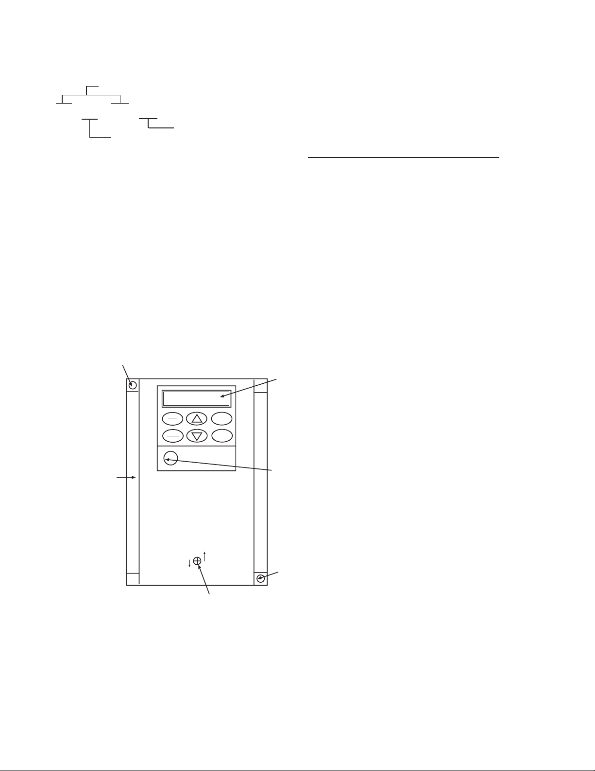
2. Part Names
4
3. Warning and Caution
Improper wiring will result in damage to, and
failure of the unit. Please carefully note the
items listed below, and use the unit as indicated.
WARNING AND CAUTION
1. Do not connect the power supply to
voltage that exceeds the standard specification voltage with permissible fluctuation. (Permissible voltage: AC220V 240V)
2. Do not connect power supply to the drive
output terminals (U, V, W). Connect
power supply only to the power terminals
(L1, L2)
3. Whenever removing the drive cover,
always switch off the power supply. Do
not switch on the power supply to the
drive with the drive cover removed.
PRG
RESET
FUNC
DATA
1
CLOSED
1. Drive Cover
2. Keypad Panel
3. Frequency Setting VR
4. Mounting Screw Holes
5. Drive Cover Screw
RUN
STOP
FVR-C9S
OPEN
5
2
4. Do not touch the live part until the CRG
lamp located above the main circuit
terminals goes out.
5. Avoid using a magnetic contactor (ON/
OFF) installed in the line side of the drive
for RUN and STOP. Use the FWD-CM
3
(forward) and REV-CM (reverse) terminals
for RUN and STOP.
6. Do not connect a power factor correcting
capacitor to the output side of the drive.
7. Do not perform a megger test between
the drive terminals or on the control
4
circuit terminals.
7
Page 8

FVR-C9S-7UX
ge,
4. Specifications
Type (FVR _ _ _ C9S-7UX) F12 F25 F50 001 002
Applicable motor output
1
Rated capacity
2
Voltage [V] Three-phase 220-240V 50/60 Hz (Output voltage is proportional
Output Rating Rated current [A] 0.66 1.2 2.1 3.7 6.4
Overload current rating 150% 1 min.
Rated frequency [Hz] 50/60 Hz
Phase, voltage, frequency Single-phase 220-240V 50/60 Hz
Allowable variation in
Input power
supply
voltage/frequency
Instantaneous voltage drop
withstanding capacity
Required power supply
capacity
Adjustment Max. freq.4 [Hz]
Base freq. [Hz]
Starting freq. [Hz]
Output Accuracy Analog setting: ±1.0% of max. frequency (25±10°C)
frequency Digital setting: ±0.01% of max. frequency (-10 - +50°C)
Setting resolution Analog setting:1/255 of max. frequency
Control method Sine wave PWM control
Control Operation Keypad operation: Operation control by RUN/STOP keys
1) "Applicable motor" indicates a standard 4-pole motor.
2) "Rated capacity" indicates a capacity at 240V rating.
3) This applies to the case where momentary power failure occurs under such conditions that rated voltage is
inputted and load factor is 85%.
4) Shows the case where an applicable motor equipped with an AC reactor (option) on the input side is used.
[Hp] 1/8 1/4 1/2 1 2
[kVA] 0.27 0.5 0.87 1.5 2.7
to input voltage)
Voltage: =10 - 15% Frequency: 15% (Imbalance in power
supply voltage: 3%)
Drive is kept running if voltage is 165V or more. If voltage drops
more than 165V from rated volta
drive is run for 15ms.
3
[kVA] 0.3 0.6 1.0 1.7 3.1
50-120 Hz Setting variable (in increments of 1 Hz)
50-120 Hz Setting variable (in increments of 1 Hz)
1-6 Hz Setting variable (in increments of 1 Hz)
(ex. 0.25 Hz / 60 Hz, 0.5 Hz / 120 Hz)
Digital Setting: 0.1 Hz (99.9 Hz max) 1 Hz (100-120 Hz)
(Extremely low noise by high frequency carrier)
Terminal strip: Forward command. Reverse command.
Coast-to-stop command. Reset.
External alarm.
C92-7-13
8
Page 9

FVR-C9S-7UX
Type (FVR _ _ _ C9S-7UX) F12 F25 F50 001 002
Applicable motor output
1
Frequency setting Key operation: Setting with UP/DOWN keys
Display Run mode Output frequency is displayed. (3 digit LED)
Acceleration/Deceleration time 0-60s (Variable setting) Acceleration time and deceleration
Control
Voltage frequency characteristics
Restart after momentary power failure "Automatic restart" setting makes it possible to keep motor
High Limiter & Low Limiter
Bias setting
Jump frequency
Torque boost
Starting torque [%] 150% for 60 seconds.
Braking torque
5
Braking DC brake Brake starting frequency: 3 Hz (fixed)
Overload Detects overload current and stops drive.
Momentary overcurrent Protects drive In case of ground fault (detects at start) and
Overvoltage Detects overvoltage of DC bus and stops drive.
Protection Overheating of cooling element Detects abnormal temp. rise of cooling element and stops drive.
Motor protection Protects standard 4-pole motor and forced-air cooled motor by
Alarm protection Outputs contact signal in case of a trip for protection
Installation location Indoor at an altitude of 3283 feet (1000m) or less and free of
Ambient temperature -10 to 50°C
Ambient humidity 20 -90% RH (There shall be no dew condensation)
Environment Vibration 19 feet/s
Storage temperature -25 to 65°C
Atmospheric pressure Operation/storage: min 900 mb (equivalent to 3283 feet (1000m)
Enclosure IP20
Cooling method Self-cooling (up to 1 Hp), forced-air cooling (2 Hp)
5) This indicates average braking torque of a single motor. (Value varies according to motor efficiency.
[Hp] 1/8 1/4 1/2 1 2
Potentiometer: Terminal for 1-5K ohm VR is provided
Analog signal: 0-5 VDC 0-10 VDC (resistance = 12k ohm)
4-20 mA (resistance = 250 ohm)
Fault mode Cause of fault is displayed.
Other LED comes on with charging voltage applied.
time can be set independently.
Setting of maximum frequency/base frequency is variable.
running and restart drive in case of a momentary power failure.
Upper limit and lower limit of frequency can be set.
Bias setting is possible with respect to analog frequency setting.
Three jump points and one jump width can be set.
Setting variable in 32 steps.
[%] 150% 1 min. 100% 1 min. 50% 1 min.
Setting of braking current / braking time is variable.
short circuit of output circuit.
means of electronic thermal overload relay.
(1c contact capacity: AC250V 0.3A cos = 0.3)
dust, corrosive gas and oil mist.
2
(5.9m/s2) or less
Vibration frequency: 5 - 55 Hz
Transport: min 660 mb (equivalent to 10720 feet (3265m)
C92-7-14
9
Page 10
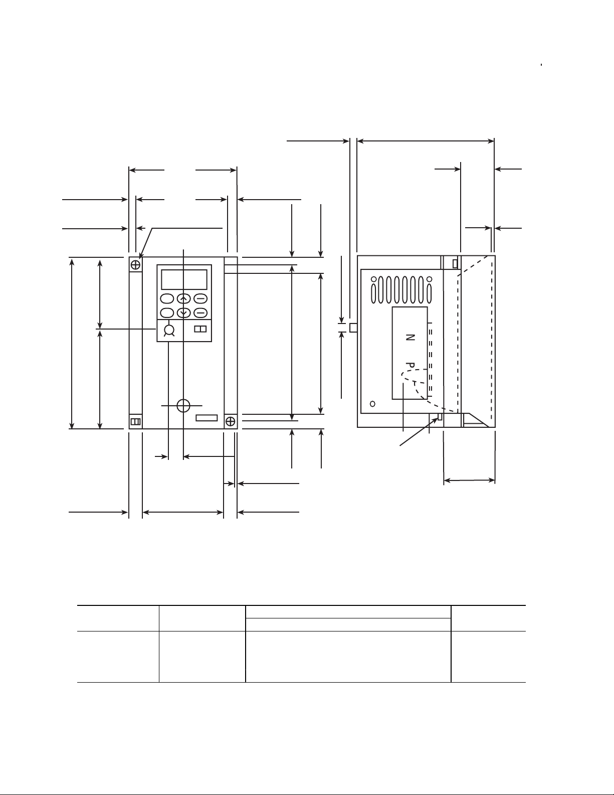
5. External Dimensions
FVR-C9S-7UX
0.24 (6.2) D
0.26 (6.5)
0.06 (1.5)
4.72 (120)
1.97 (50)2.76 (70)
3.15 (80)
2.64 (67)
2 - 0.20 X 0.24
(2 - 5 X 6.2)
0.43 (11)
0.26 (6.5)
0.06 (1.5)
0.20 (5)
4.33 (110)
0.20 (5)
D2
0.06 (1.5)
0.39 (10)
0.24 (6.2)
3.94 (100)
TERMINAL M3.5
0.39 (10)
D1
10
2.36 (50)0.39 (10) 0.39 (10)
DWG 1: FVRF12C9S-7UX to FVROO1C9S-7UX
Rated Current External Dimensions: inches (mm) DWG No.
Type [A] D D1 D2
FVRF12C9S-7UX 0.66 3.37 (85.5) 0.89 (22.5) 0.39 (10)
FVRF25C9S-7UX 1.2 3.56 (90.5) 1.08 (27.5) 0.59 (15) DWG 1
FVRF50C9S-7UX 2.1 3.96 (100.5) 1.48 (37.5) 0.98 (25)
FVR001C9S-7UX 3.7 5.53 (140.5) 2.46 (62.5) 1.97 (50)
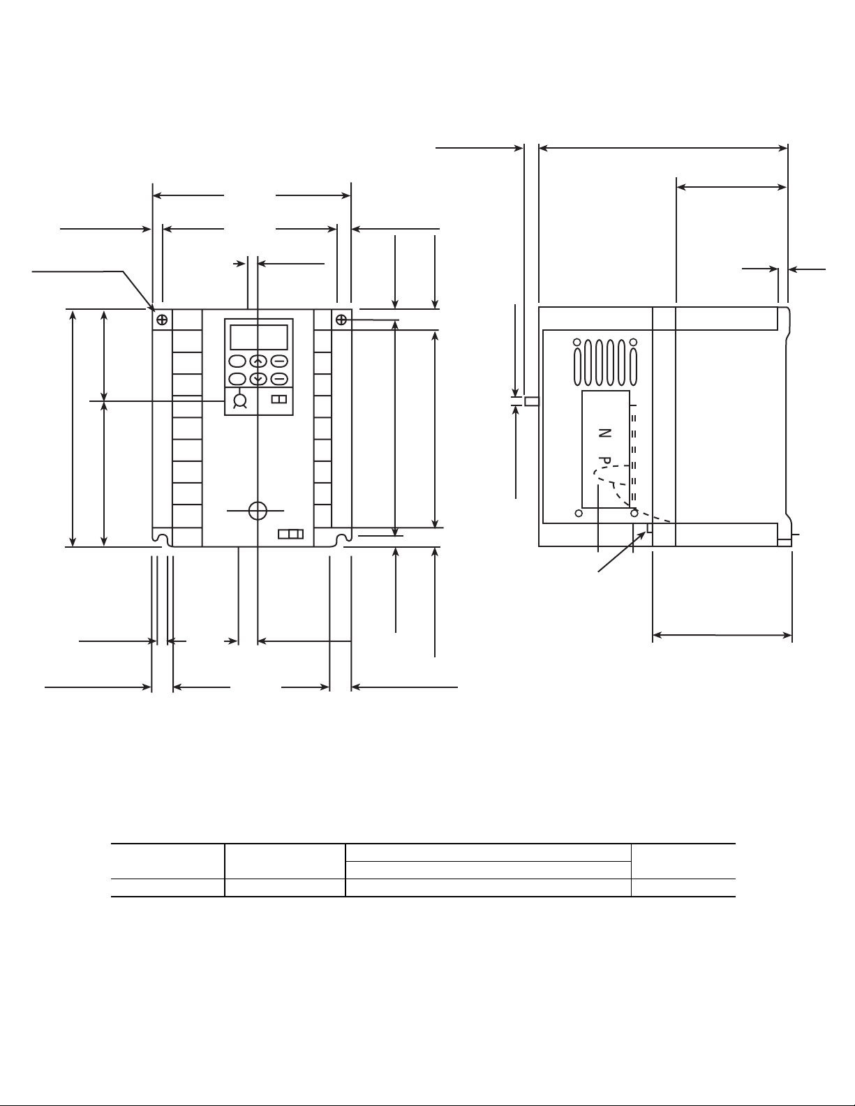
Page 11
4.33 (110)
FVR-C9S-7UX
0.24 (6.2) D
D2
0.24 (6.2)
2 - dia. 0.20
(2 - dia. 5)
5.12 (130)
1.97 (50)3.15 (80)
0.20 (5)
3.86 (98)
0.18 (4.5)
0.43 (11)
0.24 (6.2)
0.24 (6)
4.65 (118)
0.24 (6.2)
0.45 (11.5)
4.21 (107)
0.45 (11.5)
0.24 (6.2)
0.24 (6.2)
TERMINAL M3.5
D1
0.45 (11.5)
3.43 (87)
0.45 (11.5)
DWG 2: FVR002C9S-7UX
Rated Current External Dimensions: inches (mm) DWG No.
Type [A] D D1 D2
FVR002C9S-7UX 6.4 5.53 (140.5) 3.05 (77.5) 2.56 (65) DWG 2
7-'005
11
Page 12
FVR-C9S-7UX
6. Installation Instructions
Installation Conditions
Install the drive in a location which meets the
following requirements:
• The ambient temperature should be be-
tween -10°C and +50°C.
• Install the drive in the environment of
pollution degree 2. If environment is pollution degree 3 or 4, the drive should be
installed in a cabinet of IP54.
• Install the drive in the atmospheric pressure of 900mbar or more.
• Install the drive in the vibration of 232
inches/s2 (5.9m/s2) or less.
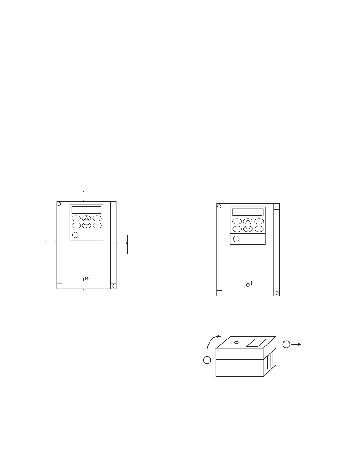
Mounting Direction and Space
3.94”
(10cm)
Mounting plate: Heat sink temperature will
reach +90°C during operation. Please use
thermostable material for drive mounting
plate.
Multi-mounting: When 2 or more drives are
installed within the drive switchboard, arrange them side by side, keeping space
(shown in the above figure) between each
drive. If the drives must be lined up vertically,
provide adequate ventilation so that the hot
air from each drive will not affect the one
above it.
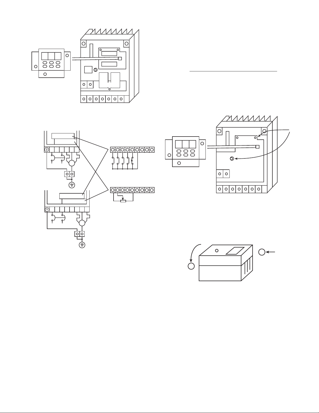
7. Wiring
Perform wiring in accordance with the following procedure:
1) Remove the cover mounting screw at the
center of the cover.
0.394”
(1cm)
PRG
RESET
FUNC
DATA
CLOSED
FVR-C9S
OPEN
3.94”
(10cm)
RUN
STOP
0.394”
(1cm)
NOTICE: The durability and reliability of the
drive will be affected by the ambient temperature. Do not place the unit where ambient temperature is not proper.
Direction: Insert M4 size screws in the
mounting screw holes in the left upper and
right lower of the drive, and install the drive
with these screws. Install the drive vertically.
Horizontal or other positional installation will
cause the drive to overheat.
PRG
RESET
FUNC
DATA
CLOSED
Cover Mounting Screw
RUN
STOP
FVR-C9S
OPEN
2) Hold the lower end of the cover, lift it up
and remove the cover
2
1
Side view of inverter
12
Space: The drive will generate heat during
operation. Allow sufficient space around the
unit as shown in the above figure.
3) Remove the keypad panel from the main
unit, and disconnect the harness from the
CN2 at the same time.
Page 13
8. 8. 8.
Disconnect
CN 1
FVR-C9S-7UX
CN 2
Note 3) Connect the power supply of over
voltage category II. If the power
supply is over voltage category III,
place the devices to limit the over
voltage below 2.5kV.
Required for CE Certification.
4) Arrange the main circuit and the control
circuit wiring as follows.
L1
Power Supply
FVRF12C9S-7UX to FVR001C9S-7UX
L1 L2 U V W
Power Supply
FVR002C9S-7UX
L2 U V W
M
3-Phase
motor
Cabinet PE
terminals
M
Cabinet PE
3-Phase
motor
terminals
CRG Lamp
B
X
1
1
1
6
5) Reinstall the cover. Connect the harness
of the keypad panel to the CN2 on the main
unit, then reinstall the keypad panel fitting it
onto the guide pins.
Connect
R
R
F
T
3
S
E
W
HRC
T
V
D
3 5 7742
1
1
3
2
6 76
3
O
O
M
C
B
Note 1
3
O
F
A
M
Note 2
8. 8. 8.
CN 1
CN 2 CN 2
Guide Pin
6) As shown below, reinstall the cover onto
the drive main unit, and fix it with the mounting screw.
1. Motor coast-to-stop
2. Reset signal
3. Reverse-direction operation command
4. Forward-direction operation command
5. External alarm
6. Frequency setting VR
7. Combined alarm relay output
Note 1) FWD and THR are connected to CM
at the factory. In this condition,
starting/stopping can be performed
via RUN/STOP keys on the keypad
panel.
Note 2) In case of using an external potenti
ometer, remove the connector
which the keypad panel and the
CN2 on the drive main unit are
connected.
1
2
Side view of inverter
13
Page 14
FVR-C9S-7UX
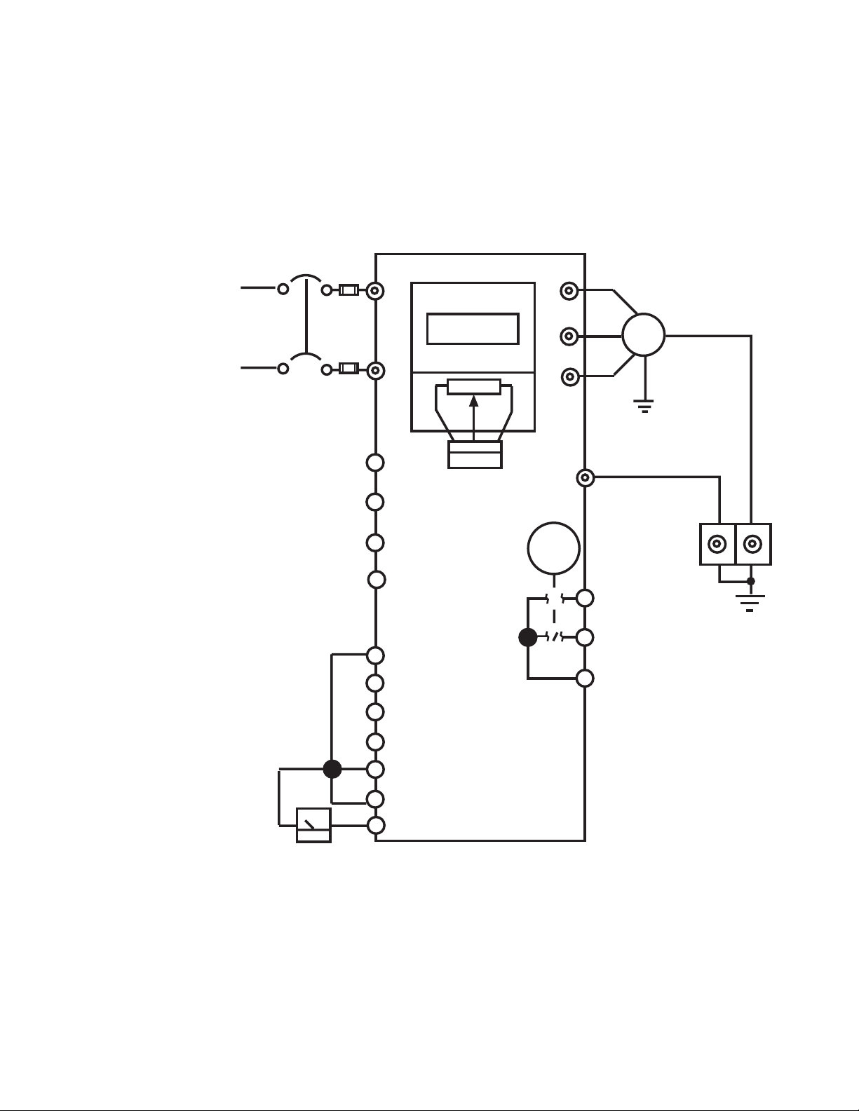
8. Basic Wiring Diagram
1) Keypad Panel Operation
From the factory, the drive is set for frequency control by means of the potentiometer control
knob on the keypad panel. The RUN/STOP function of the drive is controlled by the RUN/
STOP keys on the keypad panel.
FAB
Power Supply
AC220 - 240V
50/60 Hz
1-phase
L1
L2
13
12
11
C1
FWD
REV
8 8 8
CN2
E(G)
Fault
U
V
W
M
★
PE
30A
30B
30C
14
RST
BX
CM
THR
FM
10V 1mA
* PE terminal blocks for the drive and motor should be provided in the cabinet in which the
drive is installed in.
Page 15

FVR-C9S-7UX
2) External Signal Operation
Ensure that the connection is as shown in the following diagram in case of operating the drive
by means of external frequency setting potentiometer or contact signal.
Power supply
AC220-240V
50/60Hz
1 Phase
Potentiometer for
frequency setting
Forward-direction operation command
Reverse-direction operation command
Motor coast-to-stop command
Alarm reset
FAB
E(G)
L1
L2
13
12
11
C1
FWD
REV
BX (X2)
RST
888
CN2
U
V
W
E(G)
Fault
Thermal Relay
M
x
★
PE
30A
30B
30C
External alarm input
Analog monitor
10V 1mA
CM
THR (X1)
FVR-C9S
FM
Note 1) Set function F02 to 1.
Note 2) In case of using an external frequency setting potentiometer, disconnect the potentiometer connector (CN2) from the keypad panel. Use of an external potentiometer together
with the potentiometer on the keypad panel may result in damage to the drive.
* PE terminal blocks for the drive and motor should be provided in the cabinet in which the
drive is installed in.
15
Page 16

FVR-C9S-7UX
CAUTION:
The control circuit terminal wiring should be
kept as far as possible from the main circuit
wiring to prevent operational error due to
noise interference. Never install them in the
same duct or conduit. (A separation distance
of 4 inches [10cm] or more is recommended.) If the control circuit wiring must
cross the main circuit wiring, make sure it
crosses at a right angle.
Use shielded, twisted wire for the control
circuit wiring , which should be as short as
possible (65 feet [20m] or less).
Install a surge absorber in parallel with any
magnet contactors, solenoids, relays or
timer coils, which are close to the drive.
Long wiring lengths between the motor and
the drive will result in increased capacitance
and leakage current. This may cause earlier
activation of such protective functions as:
overcurrent protection, overheating protection and electronic thermal overload, or the
error in current detection may become large.
To avoid these, adjust the length of wiring
between the drive and the motor so that is
does not exceed the length shown below.
FVRF12C9S-7UX : 165 feet (50m)
FVRF25 to 002C9S-7UX : 325 feet (100m)
9. Application of Wiring and Equipment
Applicable motor output [Hp] 1/8 1/4 1/2 1 2
Drive type FVRF12 FVRF25 FVRF50 FVRF001 FVRF002
C9S-7UX C9S-7UX C9S-7UX C9S-7UX C9S-7UX
Output rated capacity [kVA] 0.27 0.5 0.87 1.5 2.7
Applicable wire size Main circuit 14 12
(AWG) Contol circuit 24
MCCB 6 10 16 20
ELCB 6 10 16 20
Listed fuse* 20 30
* The use of quick-acting fuses is required to validate UL listing. The factory
recommendation is Bussman type JKS or equivalent.
C92-7-15
16
Page 17

FVR-C9S-7UX
10. Terminal Function Explanation
Terminal Function Explanation
Classi-
fication
Terminal Code Terminal Name Explanation of Function
Main
Circuit
Frequency
Setting
Control
Input
L1, L2
U, V, W
E (G) Drive Grounding Terminals
13
12 Frequency Setting Voltage Input DC 0 - +10V / 0 - 100% (Input resistance: 22K ohm)
11*
C1
FWD
REV
Commercial power supply input
terminals
Drive Output Terminals For connection of a 3-Phase motor
Power Supply for Frequency
Setting
Frequency Setting Common
Terminal
Frequency Setting
Current Input (+)
Forward/Stop Command Input
Terminal
Reverse/Stop Command Input
Terminal
For connection of 1-Phase 220 to 240V commercial power
supply
Grounding terminal of drive chassis (case). Be sure to ground
the drive to prevent electric shock or to lower noise
Used as a power supply for frequency setter (variable
resistor: 1 - 5K ohm) (DC + 10V, 10mA max)
Common terminal for frequency setting signals 12 and 13
DC4 to 20 mA / 0 to 100% (Input resistance: 250 ohm)
Forward-direction operation takes place when FWD-CM is
closed. Drive decelerates and stops when FWD-CM is
opened
Reverse-direction operation takes place when REV-CM is
closed. Drive decelerates and stops when REV-CM is opened
BX
THR External Alarm Input Terminal
RST Alarm Reset Terminal When RST-CM is closed, the drive fault is reset.
CM* Control Input Common Terminal Common terminal for control input signals
* Electric potential of 11 terminal is identical with that of CM terminal.
Motor Coast-to-Stop Input
Terminal
•Drive output is cut off instantly and motor will coast-tostop when BX-CM is closed. Alarm signal is not outputted.
•This functions as multistep frequency selection terminal X2
when changing function.
•When THR-CM is opened during operation, drive output is
cut (motor will coast-to-stop) and an alarm signal is
outputted. This signal is latched and reset by RST input.
•This functions as multistep frequency selection terminal X1
when changing functions.
C92-7-03
17
Page 18

FVR-C9S-7UX
Terminal Function Explanation cont.
Terminal Function Explanation
Classi-
fication
Output for
Motor
Terminal Code Terminal Name Explanation of Function
FM Analog Monitor
Outputs + 10VDC between FM and CM terminals. When
frquency setting is equal to the maximum frequency setting,
outputs + 10VDC at 150% current when monitoring output
current.
• Two DC voltmeters (internal resistance of 10K ohm or
greater) can be connected.
• In case of DC ammeter (1mA full scale), it is necessary to
add series resistance of 10K ohm (1/2W)
• This output is a pulse output constant frequency (38. 1 Hz)
which has a variable duty.
Contact
Output
30A, B, C
Combined Alarm Output
Terminals
Output via no volt signal (contact1c) to indicate that the
drive's protective function has been activated by an alarm.
• Contact capacity (DC48V. 0.3A)
C92-04
18
Page 19

FVR-C9S-7UX
11. Operation
Pre-Operation Inspection
• Check for wiring errors.
• Check that all loose wire stands, metal
chips and unnecessary screws, etc. have
been removed.
• Check that no screws, terminals, etc. are
loose.
• Check that the wire ends of crimp terminal
are not in contact with other terminals.
Test Run Check Points
• Smooth rotation and correct rotation
direction.
• No abnormal vibrations and noise from
the motor.
• Smooth acceleration and deceleration.
• The drive is shipped with a factory installed jumper, between FWD-CM. Only
forward operation is possible. To enable
reverse operation, remove the jumper
from FWD/CM and install the jumper
between REV-CM.
• RUN/STOP by terminal operation (F02 : 1)
Note: Open FWD and REV terminals when
changing F02 data. Data cannot be changed
if not open.
Frequency
Frequency Setting Method
• Frequency setting by potentiometer control (factory preset at the time of shipment; F01:1). As wired at the factory,
frequency setting can be performed by
turning the potentiometer control knob on
the keypad panel. Turn the potentiometer
control knob clockwise to increase frequency.
• Frequency setting by digital signal (F01 :
0). With the function F01 set to 0, frequency can be increased or decreased by
the
UP/DOWN) keys on the keypad panel.
UP: Frequency up
DOWN: Frequency down
RUN/STOP Method
• RUN/STOP by keypad panel operation
(Factory preset at the time of shipment
F02:0).
RUN
Frequency
FWD-CM
REV-CM
STOP
Forward
ON
Time
Reverse
ON
19
Page 20

FVR-C9S-7UX
g
g
Selecting Operation Method
With the FVR-C9S Series, the following
methods can be selected to input the
RUN/STOP signals and for frequency
setting.
RUN/STOP
Keypad panel
1
operation
RUN/STOP Keys
2
F
02= 0 F01= 1
Terminal operation
3
(operation by external
signal, FWD/REV
terminals)
4
F
02= 1 F01= 1
* The frequency setting rate of change increases when FUNC/DATA key and UP/DOWN keys
are pressed simultaneously
Frequency Settin
UP/DOWN Keys*
Analog signal (DC0 - 10V)
UP/DOWN Keys*
Analog signal (DC0 - 10V)
Function Code settin
F01= 0
F01= 0
C92-07
20
Page 21

12. Keypad Panel
Part Names and Functions
FVR-C9S-7UX
Digital monitor:
In program mode, the keypad displays the various
function codes and data
values. During operation, it
displays the output frequency, current, voltage,
etc. If a fault occurs, the
causes of the problem will
be displayed as a code.
PROGRAM key (RESET
key): Normal mode or
program setting mode
select key. If a fault occurs,
this key is used to reset the
fault.
FUNCTION key (DATA key):
During normal mode, this key can be used to
change the display unit (frequency display
and output current display) while operation is
either stopped or running. During the program setting mode, this key can be used to
read and write the function codes and data.
8. 8. 8.
PRG
RESET
FUNC
DATA
RUN key: This key is used
for starting operation. The
LED (green) lights up during
operation. This key does
not function when terminal
operation control F02_ _ 1
RUN
is selected.
STOP
STOP key: This key is used
for stopping operation. This
FVR-C9S
UP/DOWN keys: These keys increase or
decrease the frequency. When unit is in
program setting mode, they change the
function code or data values.
key does not function when
terminal operation control
F02 _ _1 is selected.
Controlling Method for Keypad Panel
FUNC
1) Monitor change
During the normal mode, frequency display and
output current display can be changed by
pressing the FUNC/DATA key.
2) Run/Stop
When F02 is _ _ 0): Press RUN to run drive; press STOP to stop drive.
3) Frequency change
When F01 is _ _ 0: Press UP to increase frequency; press DOWN to decrease frequency.
Note) If FUNC/DATA is pressed while pressing UP or DOWN, frequency changing speed
increases.
4) Function setting method
6 0. 0
DATA
1. 2 A
FUNC
DATA
21
Page 22

FVR-C9S-7UX
Method Operation Procedure Display
1 PRG/RESET
2 UP/DOWN
3 FUNC/DATA
4 UP/DOWN
Press this key to switch to the
program setting mode.
Press UP key or DOWN key to
select function code
Press this key to display function
code.
Press UP key or DOWN key to
change function code data.
5 FUNC/DATA Press this key to store data.
6
Change other
function code
PRG/RESET
Press this key to cancel program
mode
60.0
F00
F01
1
1
F02
60.0
C92-06
22
Page 23

Function Code Tables
Function
Code
Function Date Code Range Unit
FVR-C9S-7UX
Min.
Set.
Factory
Setting
Change
During
Operation
F00 Data protection
F01
F02
F03
F04 Base Frequency 50 - 120 Hz Hz 1 60 Hz No
F05 Acceleration TIme 0.0 - 60s (0.0 setting = 0.01s) s 0.1 6.0s Yes
F06 Deceleration Time 0.0 - 60s (0.0 setting = 0.01s) s 0.1 6.0s Yes
F07 Torque Boost 0 - 31 (code) — — 13 Yes
F08
Frequency
Command
Operation
Command
Maximum
Frequency
Electronic Thermal
Overload Relay
Operation
0: Data change possible
1: Data change not possible
0: Keypad panel (UP/DOWN keys)
1: Analog input (VR, DC0 - 10V or DC4 - 20mA)
0: Keypad panel operation (RUN/STOP keys)
1: External signal operation (FWD/REV terminals)
50 - 120 Hz Hz 1 60 Hz No
0: Inactive
1: Active (standard 4-pole motor)
2: Active (forced-air cooled motor)
—— 0 No
—— 1 No
—— 0 No
—— 0 No
Electronic Thermal
F09
F10
F11
F12
F13 DC Brake (Time) 0.0 (inactive) 0.1 - 30s s 0.1 0.1s Yes
F14 Starting Frequency 1 - 6 Hz Hz 1 1 Hz No
Overload Relay
Level
Restart after
Momentary Power
Failure
Gain for Frequency
Setting Signal
DC Brake (Level
Setting)
30 - 105% of rated current of drive % 1 100% No
0: Inactive
1: Active (Restart drive in 0.5s after power failure)
0: For 0 - 10 V
1: For 0 - 5 V
0 - 100% — 1 50% Yes
—— 0 No
—— 0 No
C92-01
23
Page 24

Function Code Tables
Function
Code
Function Date Code Range Unit
FVR-C9S-7UX
Min.
Set.
Factory
Setting
Change
During
Operation
F15
F16 Fault Memory
F17 Data Initialization
F18 Retry
F19
F20
F21 Jump Frequency 1 0 - 120Hz Hz 1 0 Yes
F22 Jump Frequency 2 0 - 120 Hz Hz 1 0 Yes
F23 Jump Frequency 3 0 - 120 Hz Hz 1 0 Yes
F24 High Limiter 0 - 100% % 1 100 Yes
Motor Running
Sound
Motor
Characteristics
Jump Frequency
Range
0 - 5 (code) — — 5 Yes
The current and previous 3 fault events are displayed
in order of occurrence
0: Inactive
1: Reset to the initial value (value set at factory)
0: Inactive
1: Active (Retry times fixed at 5, Retry starts in
.05s after trip)
0 - 10 — — 4 Yes
0 - 10Hz Hz 1 3 Yes
—— — No
—— 0 No
—— 0 No
F25 Low Limiter 0 - 100% % 1 0 Yes
F26 Bias Setting 0 - 100% % 1 0 Yes
F27
F28
F29
F30
F31
F32 Meter Adjustment
F33
*1 Frequency can be set in increments of 0.1 Hz within a range of 0.0 to 99.9 Hz, and can be set in increments of 1 Hz
THR Terminal
Function
BX Terminal
Function
Multistep Speed
Setting 1
Multistep Speed
Setting 2
Multistep Speed
Setting 3
Meter Output
selection
0: External alarm input
1: Multistep speed selection (X1)
0: Motor coast-to-stop command input
1: Multistep speed selection (X2)
0.0 - 120 Hz Hz 1* 10.0 Hz Yes
0.0 - 120 Hz Hz 1* 20.0 Hz Yes
0.0 - 120 Hz Hz 1* 30.0 Hz Yes
0 - 99 (Full scale DC 6.5 - 10.5V)
0: Output frequency monitor
1: Output current monitor
—— 0 No
—— 0 No
— 1 85 Yes
— 1 0 Yes
C92-02
24
Page 25

FVR-C9S-7UX
Base
frequency
V
1
Maximum
voltage
Detailed Explanation of Each Function Code
F 0 0 Data Protection
The set data can be locked so that it will not be changed by mistake.
0 Data change possible
1 Data change not possible
To change data simultaneously press the STOP key and either the UP/DOWN key.
F 0 1 Frequency Command
Either of the following two frequency setting methods can be selected.
0 Keypad panel setting (UP/DOWN keys)
1 Analog input (setting by volume control, 0 -10VDC or 4 - 20mA)
F 0 2 Operation Command
Either of the following two control methods can be selected.
0 Keypad panel operation (RUN/STOP keys)
1 External signal operation (FWD/REV keys)
F 0 3 Maximum Frequency
Sets the maximum value for the output frequency
50
120
Multipurpose motors and other motors which are designed to operate at
low speed can be damaged if operated at high frequency. Be sure to set the
frequency to match the characteristics of the motor.
F 0 4 Base Frequency
Sets the base frequency (the frequency which is the divergent point of the specified torque characteristics
and the specified output characteristics).
50
120
Frequency can be set in increments of 1 Hz within a range of 50 to 120 Hz
Frequency can be set in increments of 1 Hz within a range of 50 to 120 Hz
V
1
Maximum
frequency
— Set to match the characteristics of the motor.
—
Although the base frequency may exceed the maximum
frequency, in that case the voltage will be decreased accordingly.
F 0 5 Acceleration Time
F 0 6 Deceleration Time
0. 0
60.0
Note: 0.0s setting is taken for 0.01s for acceleration and 0.1s for deceleration.
The time required to reach the maximum output frequency can be set within a range of
0.0s to 60s (in increments of 0.1s).
25
Page 26

FVR-C9S-7UX
F 0 7 Torque Boost
Can be set from among 32 different levels in accordance with the type of load, the
characteristics of the motor, etc.
0
For a reduced torque load (fan, pump, etc.)
1
2 Low
Output
voltage
High
3 1 High
8 Set to match this when using a Fuji FV motor designed for use with a drive.
F 0 8 Electronic Thermal Overload Relay
Either of the following two can be selected.
0 Inactive
1 Active (electronic thermal overload relay protection) For a standard 4-pole motor
2 Active (electronic thermal overload relay protection) For a Fuji FV motor
F 0 9 Electronic Thermal Overload Relay Level
Sets the operation level for the electronic thermal overload relay.
30
105
Setting value (%) = K X X 100
Setting range: 30 to 105% (increments of 1%)
Motor's rated current
Drive's rated current
Low
Output frequency f
26
Drive Capacity Wiring Length : feet
0 130 165 325 655
F12C9S-7UX K = 1.2 External thermal OL relay is recommended
F25C9S-7UX K = 1 K = 1.1 K = 1.2
F50C9S-7UX K = 1 K = 1.1
001C9S-7UX K = 1
002C9S-7UX
C97-10
Page 27

FVR-C9S-7UX
Derating characteristics for the continuously allowable current
1) For a standard 4-pole motor _ _ 1 2) for a forced-air cooled motor _ _ 2
110 -
100 -
90 80 70 60 50 40 30 20 10 -
0 -
Continuously allowable current
0 10 20 30 40 50 60 70 8 0
Setting value
Drive frequency (Hz)
105%
30%
110 -
100 -
90 80 70 60 50 40 30 20 10 -
0 -
Continuously allowable current
0 10 20 30 40 50 60 70 8 0
Setting value
Drive frequency (Hz)
105%
30%
27
Page 28

FVR-C9S-7UX
Drive Model F12 F25 F50 001 002
Time(s) 0.7 0.7 1.4 1.4 4.0
F 1 0 Restart After Momentary Power Failure
It is possible to select whether or not to restart operation when power supply is resumed after
momentary power failure.
0 Inactive While stopped: Stopped condition is maintained even after power supply
has been restored.
While running: After power supply has been restored. LU is lit and an alarm
is outputted.
1 Active Operation is restarted in 0.5s after power supply has been restored.
(When drive is stopped, it is maintained in the stopped condition even after
power supply has been restored).
This is valid only if power supply is restored while LU is lit. The length of
time that LU will remain lit after a power failure occurs is as follows.
F 1 1 Gain for Frequency Setting Signal
Outputs a frequency which is a proportional ratio of the analog frequency setting.
Selects an analog input signal level when F O 1 is _ _ 1.
0 Maximum frequency is outputted at 10V
1 Maximum frequency is outputted at 5V
When used together with the frequency setting bias,
this frequency setting gain takes priority, and the
bias applied to the frequency after the gain has
been applied.
100%
1
Frequency setting
5V 10V
Analog input
F 1 2 DC Brake
The current level of DC brake can be set.
Taking the rated current of the drive as 100%, this current level can be set in increments of 1%.
F 1 3 DC Brake (Braking Time)
The DC braking time can be set.
0.0 Inactive
0.1 - 30.0 Braking time can be set within a
range of 0.1 to 30s (in increments of 0.1s)
0
28
Output
frequency
3 Hz
Output
voltage
Time
1 DC braking
Page 29

FVR-C9S-7UX
F 1 4 Starting Frequency
The starting frequency can be set in increments of 1 Hz within a range of 1 to 6 Hz. Note that stopping will
also occur at the frequency set by this function.
1 1 Hz
6 6 Hz
Set to 2 Hz when using a high speed motor.
F 1 5 Motor Running Sound
The sound of the motor operation can be changed by changing the carrier frequency.
0
Select from among 5 levels in accordance with the usage conditions.
5
Data code
0 Low carrier frequency
5 High carrier frequency (low noise)
Output
frequency
Starting
frequency
1
F 1 6 Fault Memory
The current and previous 3 fault events are stored in memory.
The data for each can be displayed by using the DOWN key.
The procedure for displaying the data is as follows:
No. Procedure
1
Press FUNC/DATA Key
2
Press DOWN Key
3
Press DOWN Key
4
Press DOWN Key
5
Press DOWN Key
6
Display
F16 F16
Press UP Key
F01
Press UP Key
OH2
Press UP Key
OC1
Press UP Key
---
End
Display
(ex) Remarks
The information for the latest
trip will be displayed
The information for the first
preceding trip will be displayed
The information for the second
preceding trip will be displayed
The information for the third
preceding trip will be displayed.
(in this example, there is no
history of a third preceding trip).
C92-12
The information for any new trip will be stored in the area for the "information for the latest trip" shown
above, each trip history will be removed downward and the "information for the third preceding trip"
will be erased.
29
Page 30

FVR-C9S-7UX
F 1 7 Data Initialization
Reset the data for all of the functions to the value set at the factory.
0
Inactive
1
Resets to the value set at the factory.
From the _ _ 0 display, by simultaneously pressing STOP and UP, the display will change to _ _ 1.
By pressing FUNC/DATA in this state, the data will be reset to the value set at the factory, and the mode
will automatically change to the 6 0. 0 frequency display mode.
F 1 8 Retry
The number of times of retry for automatic restart after the drive has been tripped can be set.
0
The number of retry times is fixed at 5. Retry takes place in 0.5s after trip
1
Note that the retry takes place only in the case where the drive is tripped due to overcurrent or
overvoltage applied during operation.
F 1 9 Motor Characteristics
Used to compensate for output current instability.
F 2 0 Jump Frequency Range
F 2 1 Jump Frequency 1
F 2 2 Jump Frequency 2
F 2 3 Jump Frequency 3
Frequency is jumped so that the mechanical common point of load and the output frequency of drive do not
coincide with each other.
Jump
Width
Output
frequency
50X
50X
Jump frequency 1
Jump frequency 2
Jump frequency 3
30
Set frequency
Jump width is changeable within
0-10 Hz range in a unit of 1 Hz.
Page 31

FVR-C9S-7UX
F 2 4 High Limiter
F 2 5 Low Limiter
The upper and lower and lower limits of the output frequency can be set.
0
Set as a percentage of the maximum frequency in increments of 1% within a range of 0 to 100%
100
If the value set for low limiter is higher than that set for the
high limiter, the high limiter will take priority and the low
limiter will be ignored. Thus, operation will always be in
accordance with the high limiter value regardless of the
frequency setting.
F 2 6 Bias Frequency
Outputs a bias frequency with respect to the analog frequency setting.
0
Set as a percentage of the maximum frequency in increments of 1% within a range of 0 to 100%
100
100%
100%
Output
frequency
High
limiter
Low limiter
100%
Frequency
setting
Output
frequency
Bias
Frequency
setting
100%
F 2 7 THR Terminal Function
This function enables terminal THR to be used for two different functions by changing the data
code as follows:
0
External alarm input
1
Multistep speed selection (X1)
This function data cannot be changed during operation. (Possible to change only in STOP mode).
F 2 8 BX Terminal Function
This function enables terminal BX to be used for two different functions by changing the data code as follows:
0
Motor coast-to-stop command input
1
Multistep speed selection (X2)
This function data cannot be changed during operation. (Possible to change only in STOP mode).
31
Page 32

FVR-C9S-7UX
F 2 9 Multistep Speed Setting 1 (Speed 1)
F 3 0 Multistep Speed Setting 2 (Speed 2)
F 3 1 Multistep Speed Setting 3 (Speed 3)
Multistep speeds can be set within a range of 0 to 120 Hz only by changing the contact signal from outside.
(X1-CM X2-CM). Setting of speed of optional step is possible within a range of 0 to 120 Hz during drive
operation
(Note1) X1 or X2 terminal is selected via THR/BX terminal function change (F27, F28)
(Note 2) In selecting THR/BX terminal function (F27, F28) individual setting is possible.
Terminal / Function Code F27 : 1 F27: 0 F27: 1 F27: 0
F28: 0 F28: 1 F28: 1 F28: 0
THR X1 External Alarm input X1 External alarm imput
BX
Speed 0 Frequency setting is made by either the analog signal or the keypad panel.
Motor coast-to-stop
command imput
X2 X2
Speed 1
Speed 2
Speed 3
Speed 0
Motor coast-to-stop
command imput
C92-09
32
THR-CM (X1)
BX-CM (X2)
FWD-CM
ON
Time
ON
ON
ON
Page 33

FVR-C9S-7UX
F 3 2 FM Terminal Output Level Calibration
Adjust the level of the voltage output to terminal FM for the frequency meter.
0
Approximate DC 6.5V at full scale
99
Note: The FM terminal output is a pulse output of which frequency is constant (38.1 Hz) and duty is variable.
F 3 3 FM Terminal Function Selection
With regard to the data outputted to the FM terminal, either the output frequency or the output current
can be selected.
Approximate DC 10.3V at full scale
0
Output frequency
1
Output current
FM
CM
33
Page 34

14. Protective Functions
FVR-C9S-7UX
Function
Momentary
Overcurrent
Protection
Overvoltage
Protection
Undervoltage
Protection
Protection against
overheating of
cooling element
External Alarm Input
Electronic Thermal
Overload
Drive Overload Detects overload of drive and stops drive. OLU Yes
Stops drive to protect it against overcurrent .
OC1 = During acceleration
OC2 = During deceleration
OC3 = During constant speed operation
Detects overvoltage of DC intermediate circuit and stops drive. OU Yes
Detects undervoltage of DC intermediate circuit and stops drive. LU Yes*
Detects abnormal temperature rise of cooling element and stops drive OH1 Yes
Stops drive by input of an external signal. OH2 Yes
Detects overload of motor and stops drive. OL Yes
Explanation
Display
OC1
OC2
OC3
Alarm Output
Yes
Memory Error Stops drive in case of memory error Er1 Yes
CPU Error Stops drive in case of a CPU error Er3 Yes
* This output is selectable by F10
C92-05
34
Page 35

FVR-C9S-7UX
15. Warranty Parts and Service
The purpose of the following section to
provide specific instructions to the user of
the FVR-C9S-7UX drive regarding warranty
administration and how to obtain assistance
on both in-warranty and out-of-warranty
equipment.
If assistance is required to determine warranty status call:
Technical Services
GE Fuji Drives USA, Inc.
1-540-387-5739
24-hour Emergency 1-540-387-8292
Warranty Coverage
The warranty set forth in Section 1 of
FN-1090 (1/91) of GE’s Condition of Sale
covers all major parts of the drive such as
the main printed circuit boards, transistor
modules, etc. The warranty covers replacement of the entire drive.
“Warranty period is 12 months after installation or 18 months after shipment from the
Company, whichever occurs first.”
Before calling the number at left to determine warranty status, the drive serial number
will be required. This is located on the drive
nameplate. If the drive is still under warranty,
further information will be required per the
“In-Warranty Failure Checklist” shown on
page 36 of this instruction book.
Out-of-Warranty Procedures
If a defective drive is out-of-warrant contact
an Authorized GE Fuji Service Provider for
repair or an Authorized GE Fuji Distributor
for replacement.
Motors
Repairs on motors are generally handled by
the motor manufacturer. For specific instructions on your motor, call the distributor from
which it was purchased and be prepared to
furnish complete nameplate data.
35
Page 36

FVR-C9S-7UX
In-Warranty Failure Checklist
To assist with warranty troubleshooting, the following information is required. This data is needed to evaluate
the cause in an effort to eliminate any further failures.
Model No.:
Serial No.:
Start-Up Date:
Failure Date:
Status When Failure Occurred (check one):
Power-Up Running Accel Decel
Explanation of Failure:
Application Information (check Yes or No)
Input Transformer: Yes No
If Yes: KVA
L1 Volts L2 Volts L3 Volts
Power Factor Correction Capacitors: Yes No
If Yes: Microfarad
Other Equipment on Same Power Yes No
If Yes, what?
Line Reactor on Input Yes No
Input Starter Yes No
Output Starter Yes No
Motor Overloads Yes No
Control Terminals Used (circle if used)
THR X1 X2 X3 30A 30B 30C
RST/BX FWD REV C1 11 12 13
RUN RT1
Function Codes Different From Factory Settings
Function Code Setting Function Code Setting
36
Failure Message (see Section 5)
Latest Fault Previous Faults: No Message
Hz 1.
A2.
V3.
After all of the Checklist information is acquired, contact the following Service Center number for assistance:
540-387-5739 (8am - 5pm Central Standard time Monday thru Friday).
540-387-8292 (24-hour emergency)
When you return the unit for warranty you need to get a RMA number from your Service Center.
Page 37

FVR-C9S-7UX
16. Electromagnetic Compatibility (EMC)
1. General
In accordance with the provisions described
in the European Commission Guidelines
Document on Council Directive 89/336/EEC,
Fuji Electric Co., Ltd. has chosen to classify
the FVR-C9S-7UX range of drives as “Complex Components”. Classification as “Complex Components” allows a product to be
treated as “apparatus”, and thus permits
compliance with the essential requirements
of the EMC Directive to be demonstrated to
both an integrator of FVR drives and to his
customer or the installer user. FVR drives up
to 2 Hp are supplied “CE-marked”, signifying
compliance with EC Directive 89/336/EEC
when fitted with specified filter units installed
and earthed in accordance with this sheet.
This specification requires the following
performance criteria to be met.
Immunity : EN50082-2
Emissions : EN50081-1
2. RFI Filters
It is strongly recommended that the appropriate FVR input filter is used, as shown in
the followings, to limit RF current flowing
into the main supply circuit. Without an input
filter a FVR installation may not meet statutory requirement. FVR drives contain high
power semi-conductor devices which are
switched at high speeds to synthesis a nearsinusoidal current waveform across the
frequency range of the output. Rapidlychanging voltages and currents will generate
some degree of electromagnetic emission.
Emissions will be predominantly conducted
through the motor and the mains supply
cables, although some radiated emissions
will be detected in close proximity to the
drive system. It is essential that precautions
are taken both at the design stage and at the
time of installation to prevent radio frequency interference (RFI) from the drive
system affecting sensitive equipment in
close proximity.
3. Recommended Installation Instructions
It is necessary that to conform to the EMC
Directive, these instructions must be followed. Follow the usual safety procedures
when working with electrical equipment. All
electrical connections to the filter, drive and
motor must be made by a qualified electrical
technician.
1) Check the filter rating label to ensure that
the current, voltage rating and part number
are correct.
2) The back panel of the wiring cabinet of
board should be prepared for the mounting
dimensions of the filter. Care should be
taken to remove any paint etc. from the
mounting holes and face area around the
hole of the panel. This will ensure the best
possible earthing of the filter.
3) The filter should then be securely
mounted in position, and the drive mounted
to the front of the filter with the screws
provided.
4) Connect the incoming mains supply to the
filter terminals marked “LINE” and earth any
cables to the earth stud provided. And fit the
Input Ferrite Ring (if required two ferrite
rings, refer to table 1), then connect the filter
terminals marked “LOAD” to the mains input
of the drive using short length of appropriate
gauge wire.
5) Fit the Output Ferrite Ring as close to the
drive as possible and connect the motor.
Armored or screened cable should be used
with the 3 phase conductors only passing
twice through the center of the Output Ferrite Ring. The earth conductor should be
securely earthed at both drive and motor
ends. The screen should be connected to
enclosure.
37
Page 38

FVR-C9S-7UX
6) It is important that all lead length are kept
as short as possible and that incoming
mains and outgoing motor cables are kept
well separated.
7) Segregate power cables from control
wiring as possible as you can, and avoid
parallel cable runs to minimize “noise coupling”. Wherever runs of power and control
cable must cross, try to achieve this at right
angles.
Mains input
terminals
Earth Stud
L
8) FVR drives should be installed, and are
designed to operate, within an electrically
shielded metal enclosure.
The RFI filters range are designed especially
for the FVR drive and help to ensure EMC
compliance of machinery an installations
using the drives. The drives may be mounted
on top of the filter using the integral fixing
positions, the intention being that valuable
space inside wiring cabinets may be saved.
(Refer to Fig. 1 and Table 1)
N
LINE
Drive fixing
positions
L’
LOAD
Y
N’
L
Earth Stud
Load terminals
to drive
input
X
Fig. 1 RFI Filters
H
W
Table 1 RFI Filter Dimensions Conforms to EN55011 Class B
Filter Applied Rated Max Rated Dimensions inches Drive Sub
Part No. Drive Current Voltage L x W x H X Y Fixings Filters
EFL-0.2C9-7 FVRF12C9S-7UX 3A 6.69 x 3.35 x 1.38 1.97 6.1 M4 0.16 Ferrite
FVRF25C9S-7UX x0.63 (2pcs.) OC1x (1 pcs.)
EFL-0.75C9-7 FVRF50C9S-7UX 10A 1-Phase 6.69 x 3.35 x 1.38 1.97 6.10 M4 0.16
FVR001C9S-7UX 240 VAC x0.63 (2 pcs.)
EFL-2.2C9-7 FVR002C9S-7UX 16A 7.09 x 4.53 x 1.38 3.50 6.50 M4 0.16 Ferrite
x0.63 (4 pcs.) OC2x (1 pcs.)
7-'006
38
Page 39

Basic Standards: EN55011 Class B
FVR-C9S-7UX
Input
Single
contactor
Enclosure
phase
50/60 Hz
power
supply
HRC Fuses
or circuit
breaker
Noise filter
(foot mounted)
L
L’
Ferrite ring
Drive
L1
1 turn
U
Screen
V
N
N’
L2
W
PE
*2
*1
Screening must be electrically continuous and earthed at the enclosure and the motor.
E
*1and *2: These connections are to be as short as possible and earth conductor should
be as thick as possible.
39
Page 40

Power supply
single-phase
220-240V
50/60 HZ
FVR-C9S-7UX
RFI
FILTER
L
N
PE
Alarm Signal
L’
N’
L1
L2
30C
30B
30A
U
V
W
Ferrite
ring
Enclosure
Housing
Motor
M
E
Armored or
screened cable
Frequency
setting
Potentiometer
Analog
frequency
meter
3
2
1
[13]
[12]
[11]
(CM)
(FWD)
(REV)
(THR)
(EX)
[FM]
(RST)
[CM]
Fig. 3 Recommended installation detail inside the enclosure
Control
input
40
Page 41

FVR-C9S-7UX
41
Page 42

FVR-C9S-7UX
17. EC Declaration of Conformity
We Fuji Electric Co., Ltd. Suzuka Factory
5520 Minami tamagaki-cho Suzuka-city Mie-ken JAPAN
declare under our sole responsibility that the following products
Product identification
• Product : Inverter
• Brand : Fuji Electric
• Model/Type : FVRO.1C9S-7xxx to FVR1.5C9S-7xxx
(xxx stands for A to Z)
to which this declaration relates is in conformity with the EMC requirements of the following
standard(s):-
Immunity : EN50082-2 “Generic immunity standard
Part 2 (Industrial Environment)”
Emission : EN50081-1 “Generic emission standard
Part 1 (residential, commercial and light industrial)”
and conforms to the protection requirements of Council Directive :-
89/366/EEC
relating to Electromagnetic Compatibility.
When : Wired and earthed in accordance with the installation instructions. Installed
within a steel enclosure. Used in conjunction with power input filter and ferrite
rings which are recommended by Fuji Electric.
A. OKUBO
General Manager
Inverter Design Department
Suzuka Factory
42
Dated: November 20, 1997
Page 43

FVR-C9S-7UX
EC Declaration of Conformity
We Fuji Electric Co., Ltd. Suzuka Factory
5520 Minami tamagaki-cho Suzuka-city Mie-ken JAPAN
declare under our sole responsibility that the following products
Product Identification
• Product : Inverter
• Brand : Fuji Electric
• Model/Type : FVRO.1C9S-7xxx to FVR1.5C9S-7xxx
(xxx stands for A to Z)
to which this declaration relates is in conformity with the low voltage requirements of the
following standard(s) :
DIN VDEO160/1988
Category : Overvoltage category II/Pollution degree 2 and conforms to the protection
requirements of Council Directive :
73/23/EEC relating to Low Voltage.
When : Wired and earthed in accordance with the installation instructions. Installed
within a steel enclosure satisfied “Pollution degree 2”. Used in conjunction with
1AC power supply (Line) whose line is earthed for -7xxx series.
A. OKUBO
General Manager
Inverter Design Department
Suzuka Factory
Dated: November 20, 1997
43
Page 44

FVR-C9S-7UX
44
GE Fuji Drives USA, Inc.
1501 Roanoke Blvd. Suite 435
Salem, VA 24153
1-800-543-6196
Internet Address: http://www.ge.com
INR Si47-0459 b-E Printed in Japan
 Loading...