

Page 1
Installation
Built-In
Dishwasher
Instructions
If you have questions, call 800-GECARES or visit our website at: www.GEAppliances.com
READ CAREFULLY.
KEEP THESE INSTRUCTIONS.
PDW8100 Series
PDW8200 Series
PDW8500 Series
PDW8600 Series
PDW8700 Series
Page 2
Installation Preparation
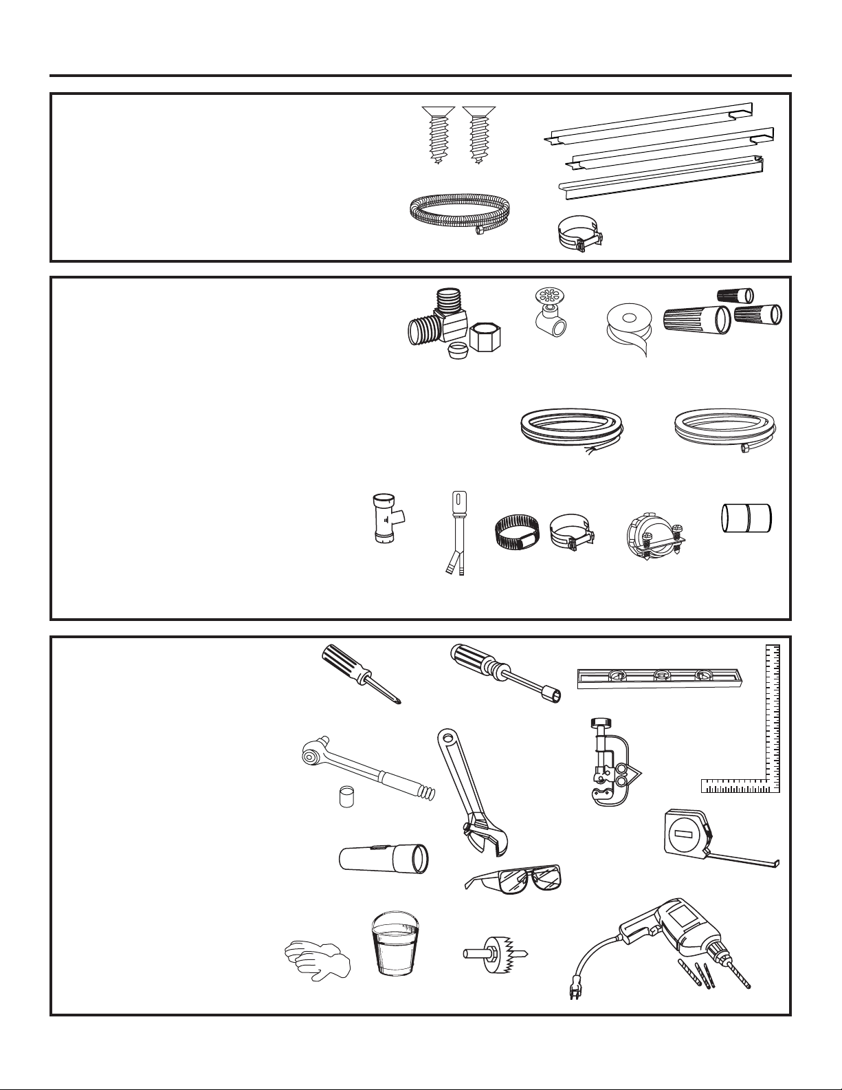
PARTS SUPPLIED:
Two #8 Phillips flat head wood screws, 5/8" long to
secure dishwasher to underside of countertop or
sides of cabinetry. (Taped to top or side of dishwasher.)
Side and top trim pieces
Trim Panel Accessory Kit (not shown).
Model PDW9700 only
Drain Hose and Hose Clamp
MATERIALS YOU WILL NEED :
Ferrule, compression nut and 90° Elbow (3/8"NPT external
thread on one end, opposite end sized to fit water supply)
Thread seal tape
UL Listed wire nuts (3)
Materials For New Installations Only:
Air gap for drain hose, if required
Waste tee for house plumbing, if applicable
Electrical cable or power cord, if applicable
Screw type hose clamps
Strain relief for electrical connection.
Hand shut-off valve
Water line 3/8" min. copper
Coupler for extending drain line, if applicable
Waste Tee
2 Wood Screws
Drain Hose
90° Elbow,
Ferrule and
Compression Nut
Air Gap
Hose Clamp
Hand
Shut-Off
Valve
Electrical Cable
(or Power Cord, if applicable)
Screw Type
Hose Clamps
Thread
Seal Tape
Strain Relief
Trim Pieces
(some models)
Wire Nuts (3)
Hot Water line
Coupler
TOOLS YOU WILL NEED:
Phillips head screwdriver
5/16" and 1/4" nutdriver
6" Adjustable wrench
Level
Carpenters square
Measuring tape
Safety glasses
Flashlight
Bucket to catch water when flushing the line
15/16" socket (optional for skid removal)
Gloves
For New Installations Only:
Tubing cutter
Drill and appropriate bits
Hole saw set
Phillips
Head
Screwdriver
15/16" Socket
Gloves
Flashlight
Bucket
2
1/4"
and 5/16"
Nutdriver
Safety Glasses
Hole Saw Set
6" Adjustable
Wrench
Level
Carpenters
Square
Tubing Cutter
Measuring Tape
Drill and Bits
Page 3
Installation Preparation
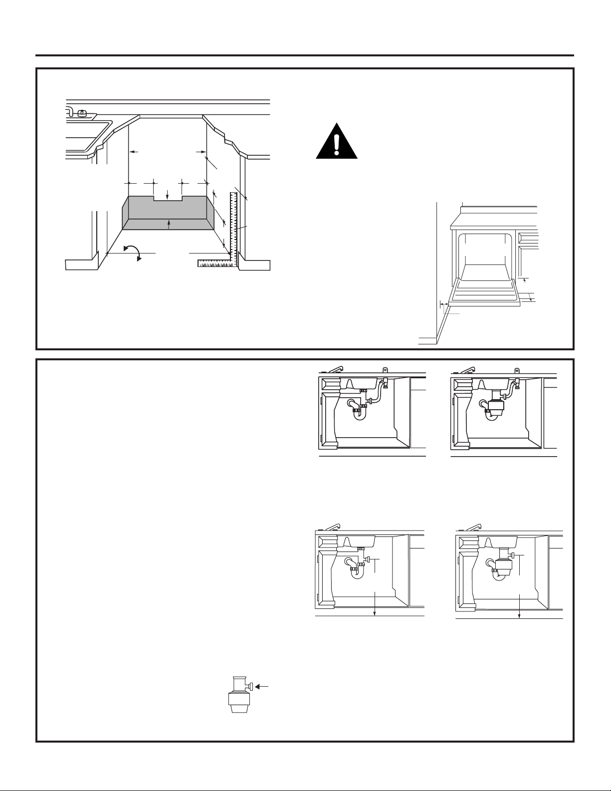
PREPARE DISHWASHER ENCLOSURE
This Wall Area
must be Free of
34-1/2"±1/4"
Pipes or wires
Underside of
5" 5"
4"
Countertop
to Floor
24" Min.
Floor MUST
Figure A
be Even with
Room Floor
Plumbing and Electric Service
Must Enter Shaded Area
• The rough cabinet opening must be at least 24" deep,
24" wide and approximately 34-1/2" high from floor to
underside of the countertop.
24"
Min.
4"
Cabinets
Square
6"
and
Plumb
• The dishwasher must be installed so that drain hose is
no more than 10 feet in length for proper drainage.
WARNING
To reduce the risk of electric shock, fire, or injury to
persons, the installer must ensure that the dishwasher
is completely enclosed at the time of installation.
CLEARANCES: When
installed into a corner,
allow 2" min. clearance
between dishwasher and
adjacent cabinet, wall or
other appliances. Allow
28-3/8" min. clearance
from the front of the
dishwasher for door
opening. Figure B
Countertop
Dishwasher
28-3/8"
Clearance for Door
Opening 2" Minimum
Figure B
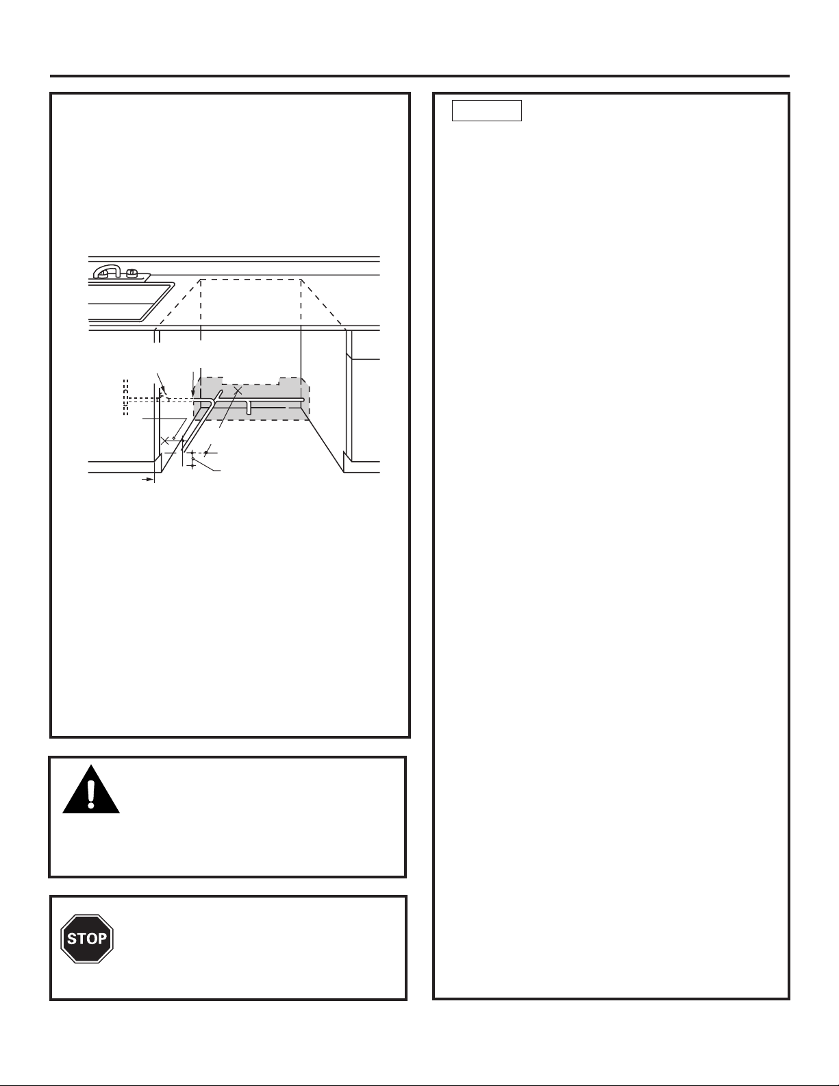
DRAIN REQUIREMENTS
• Follow local codes and ordinances.
• Do not exceed 10 feet distance to drain.
• Do not connect drain lines from other devices
to the dishwasher drain hose.
NOTE: This dishwasher is equipped with a high drain
loop. There is no minimum height required for drain hose
routing. However, 18" minimum from floor to center of
waste tee or disposer inlet is required. See Figure D.
DETERMINE DRAIN METHOD
The type of drain installation depends on the following
question.
Do local codes or ordinances require an air gap?
Is waste tee less than 18" above floor?
If the answer to either question is YES, Method 1 MUST
be used.
• If the answers are NO, either method may be used.
CABINET PREPARATION
• Drill a 1-1/2" dia. hole in the cabinet wall within the
shaded areas shown in Figure A for the drain hose
connection. The hole should be smooth with no sharp
edges.
IMPORTANT: When connecting
drain line to disposer, check to be
sure that drain plug has been
removed. DISHWASHER WILL NOT
DRAIN IF PLUG IS LEFT IN PLACE.
Remove
Hopper
Plug
Figure C
Method 1 – Air Gap with Waste Tee or Disposer
An air gap must be used when required by local codes and ordinances.
The air gap must be installed according to manufacturers instructions.
18"
Min.
Figure D
Method 2 – Built-in “High Drain Loop” with Waste Tee or
Disposer
18"
Min.
3
Page 4
Installation Preparation
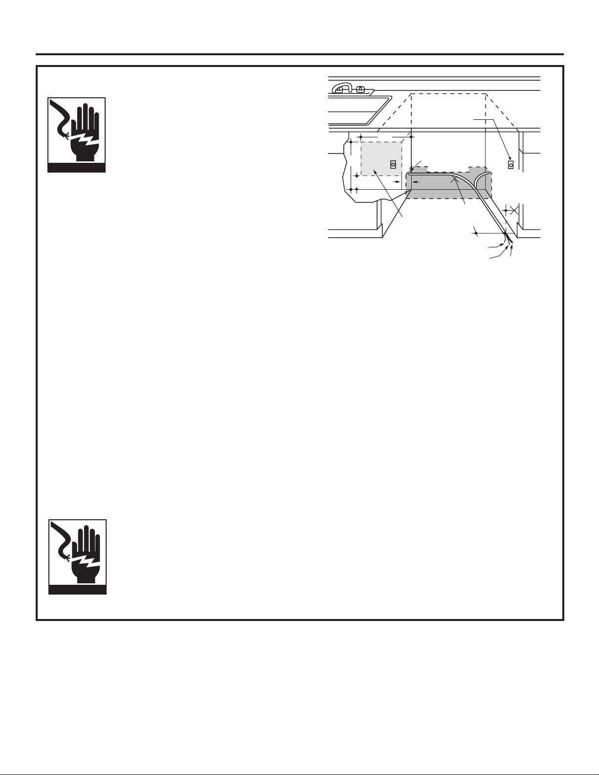
White
18"
6"
24"
from Wall
3"
from
Cabinet
Alternate
Receptacle
Location
Ground
Black
1-1/2" Dia.
Hole (Max.)
18"
6"
Receptacle
Location
Area
PREPARE ELECTRICAL WIRING
WARNING
FOR PERSONAL SAFETY: Remove
house fuse or open circuit breaker
before beginning installation. Do not
use an extension cord or adapter plug
with this appliance.
Electrical Requirements
• This appliance must be supplied with 120V, 60 Hz., and
connected to an individual properly grounded branch
circuit, protected by a 15 or 20 ampere circuit breaker
or time delay fuse.
• Wiring must be 2 wire with ground and rated for 75°C
(176°F).
• If the electrical supply does not meet the above
requirements, call a licensed electrician before
proceeding.
Grounding Instructions–Cable Direct
This appliance must be connected to a grounded metal,
permanent wiring system, or an equipment grounding
conductor must be run with the circuit conductors and
be connected to the equipment grounding terminal or
lead on the appliance.
Grounding Instructions–Power Cord Models
This appliance must be grounded. In the event of a
malfunction or breakdown, grounding will reduce the
risk of electric shock by providing a path of least resistance for electric current. This appliance is equipped
with a cord having an equipment grounding conductor
and a grounding plug. The plug must be plugged into an
appropriate outlet that is installed and grounded in
accordance with all local codes and ordinances.
WARNING
The improper connection of the
equipment grounding conductor can
result in a risk of electric shock. Check
with a qualified electrician or service
representative if you are in doubt that
the appliance is properly grounded.
Figure E
For models equipped with power cord: Do not modify the
plug provided with the appliance; if it will not fit the outlet,
have a proper outlet installed by a qualified technician.
Cabinet Preparation & Wire Routing
• The wiring may enter the opening from either side, rear
or the floor within the shaded area.
• Cut a 1-1/2" max. dia. hole to admit the electrical cable.
Cable direct connections may pass through the same
hole as the drain hose and hot water line, if convenient.
If cabinet wall is metal, the hole edge must be covered
with a bushing. NOTE: Power cords with plug must pass
through a separate hole.
Electrical Connection to Dishwasher
Electrical connection is on the right front of dishwasher.
• For cable direct connections the cable must be routed
as shown in Figure E. Cable must extend a minimum of
24" from the rear wall.
• For power cord connections, install a 3-prong grounding
type receptacle in the sink cabinet rear wall, 6" min. or
18" max. from the opening, 6" to 18" above the floor.
4
Page 5
Installation Instructions
PREPARE HOT WATER LINE
• The line may enter from either side, rear or floor
within the shaded area shown in Figure F.
• The line may pass through the same hole as the
electrical cable and drain hose. Or, cut an additional
1-1/2" dia. hole to accommodate the water line. If
power cord with plug is used, water line must not
pass through power cord hole.
Valve
2"
1-1/2" Dia.
Hole
19" From Wall
2" From Floor
Shut-off
Hot
From
Cabinet
Cabinet Face
Figure F
Water Line Connection
• Turn off the water supply.
• Install a hand shut-off valve in an accessible location,
such as under the sink. (Optional, but strongly recommended and may be required by local codes.)
• Water connection is on the left side of the dishwasher.
Install the hot water inlet line, using no less than 3/8"
O.D. copper tubing. Route the line as shown in Figure F
and extend forward at least 19" from rear wall.
• Adjust water heater for 120°F to 150°F temperature.
• Flush water line to clean out debris.
• The hot water supply line pressure must be 20-120 PSI.
STEP 1 CHECK DOOR BALANCE
• With dishwasher on the wood skid, check the door
balance by opening and closing the door.
• If the door drops when released, increase the spring
tension. If the door rises when released, decrease the
tension.
• Position the spring for increased or decreased tension
as required.
• Model families have different spring mounting holes
and tension adjustment methods. Refer to the appropriate figure for your model.
PDW8100-PDW8800 Series
Figure G
CAUTION:
Do not remove wood base until you are
ready to install the dishwasher. The dishwasher will tip
over when the door is opened if the wood base is
removed.
BEFORE YOU BEGIN
Locate and set aside the 2 Phillips head
mounting screws wrapped with yellow tape
and stuck to the top or side of the dishwasher.
TIP: If door does not open easily or falls too quickly,
check the spring cable routing. Check that the cable is
properly aligned on the pulley (as shown).
5
Page 6
Installation Instructions
STEP 2 REMOVE WOOD BASE,
INSTALL LEVELING LEGS
IMPORTANT – Do not kick off
wood base! Damage will occur.
• Move the dishwasher close to the installation
location and lay it on its back.
• Remove the four leveling legs on the underside of
the wood base with an adjustable
wrench or 15/16" socket.
• Discard base.
Figure J
• Screw leveling legs back into the dishwasher
frame, approximately 1/4" from frame as shown.
STEP 3 REMOVE TOEKICK
• Remove the two toekick screws.
Figure K
STEP 5 INSTALL 90° ELBOW
• Wrap 90° elbow with thread seal tape.
• Install a 90° elbow onto the water valve.
Figure M
• Do not over tighten 90° elbow, water valve bracket
could bend or water valve fitting could break.
• Position the end of the elbow to face the rear of the
6
dishwasher.
Page 7

Installation Instructions
STEP 6 POSITION WATER LINE
AND HOUSE WIRING
• Position water supply line and house wiring on the
floor of the opening to avoid interference with base
of dishwasher and components under dishwasher.
Figure N
STEP 7
INSTALL DRAIN HOSE,
GUIDE THROUGH CABINET
• Remove tape and wire tie holding the clamp to the
drain hose. Be careful not to damage the drain hose.
• Stand the dishwasher
upright.
• Slip the supplied
hose clamp over the
small end of the hose.
Do not tighten.
Figure O
STEP 8 SLIDE DISHWASHER
PARTIALLY INTO CABINET
DO NOT PUSH AGAINST FRONT PANEL WITH KNEES.
DAMAGE WILL OCCUR.
• Slide dishwasher into the opening a few inches at a
time.
Figure Q
• As you proceed, pull the drain hose through the opening under the sink. Stop pushing when the dishwasher
is a few inches forward of adjacent cabinetry.
• Make sure drain hose is not kinked under the dishwasher and there is no interference with the water
line and wiring or any other component.
STEP 9 INSTALL TRIM PIECES
Skip this step if trim is not supplied with the
dishwasher.
• Locate trim strips inside dishwasher.
• Press trim onto the tub flange on each side. Start with
the top edge, pressing on as you move towards the
bottom.
• Press the two top trim pieces on each side of the latch.
• Open and close the door to check that trim does not
bind and does not interfere with door latch.
Insulation
Blanket
• Position the dishwasher in front of the opening.
Insert drain hose into the cabinet side. If power cord
is used, guide the end through a separate hole.
Water
Line
Drain
Hose
House
Wiring
Power Cord
(If Used)
Figure R
7
Page 8

Installation Instructions
STEP 10 POSITION DISHWASHER UNDER COUNTERTOP
• Push the dishwasher into the cabinet.
• Push at the sides with your hands. Do not use your
knee against the door since door damage will occur.
• Check that the tub insulation blanket does not get
“bunched-up” or interfere with the springs as you
slide it into the cabinet.
• Center the dishwasher in the opening.
• Check that the edges of the dishwasher door are
behind the cabinet frame and aligned with the front
face of the cabinet as shown.
• Carefully open and close the door to ensure that the
door panel does not catch or rub on the cabinet
frame.
• If the door catches or rubs on the frame, reposition
and/or level the unit (see Step 11) until the door
moves freely and does not contact the cabinet frame.
Figure S
Positioning for
PDW9200-PDW9800 Series
The controls on these models are designed to be
hidden by your countertop. Align the dishwasher as
shown.
NOTE: If the drain hose gets “bunched-up” behind the
unit it can prevent the controls from being hidden by
the countertop.
NOTE: If this dishwasher is replacing an existing
dishwasher, the old countertop bracket screw holes
may not be in the correct position to accept a topcontrol model. New holes may be required.
TIP: The leveling legs can be used to increase or
decrease the amount of gap between the controls and
the countertop affecting the visibility of the controls.
IMPORTANT – Leave enough gap
between the controls and the countertop brackets so
that the screwheads do not contact and scratch the
controls.
Figure T
Page 9

Installation Instructions
STEP 11 LEVEL DISHWASHER
IMPORTANT – Dishwasher must
be level for proper dish rack operation and wash
performance.
• Place level on
door and rack
track inside the
tub as shown to
check that the
dishwasher is
level.
Figure X
• Level the dishwasher
by adjusting the
four leveling legs
individually.
• If adjustment to the
right rear leveling leg
is required, gain
access by loosening
junction box bracket
screw (through the
access hole) and
rotate bracket clockwise.
TIP: Pull lower rack out, about halfway. Check to
be sure the rack does not roll forward or back into
dishwasher. If the rack rolls in either direction, the
dishwasher must be leveled again.
• If door hits the tub, the dishwasher is not installed
correctly. Adjust leveling legs to align door to tub.
Figure Y
The dishwasher must be secured to the countertop or
the cabinet sides. When countertops are made of wood,
use Method 1. When countertops are granite or other
materials that will not accept screws, use Method 2 to
secure dishwasher at the sides.
Figure AA
9
Figure BB
Page 10

Installation Instructions
STEP 13 CONNECT WATER SUPPLY
Connect water supply line to 90° elbow.
• Slide compression nut, then ferrule over end of
water line.
• Insert water line into 90° elbow.
• Slide ferrule against elbow and secure with compres-
sion nut.
IMPORTANT – Check to be sure
that door spring does not rub or contact the fill hose or
water supply line. Test by opening and closing the door.
Re-route the lines if a rubbing noise or interference
occurs.
Figure CC
STEP 14 CONNECT DRAIN LINE
FOLLOW ALL LOCAL CODES AND ORDINANCES.
The drain hose molded end will fit 5/8", 3/4" or 1"
diameter connections on the air gap, waste tee or
disposer. Cut on the marked line as required for your
installation.
Cutting Lines
3/4"
1"
IMPORTANT: Do not cut corrugated
portion of hose
• If a longer drain hose is required, add up to 42" of
length for a total of 10 ft. to the factory installed hose.
Use 5/8" or 7/8" inside diameter hose and a coupler to
connect the two hose ends. Secure the connection
with hose clamps.
5/8"
Figure DD
DRAIN LINE INSTALLATION
• Connect drain line to air gap, waste tee or disposer
using either previously determined method.
Method 1 – Air gap with waste tee or disposer
Waste Tee Installation
Method 2 – Built-in “High drain loop” with waste tee or
disposer
Figure FF
Disposer Installation
Figure EE
• Secure the drain hose to the air gap, waste tee or
disposer with clamps.
NOTE: TOTAL DRAIN HOSE LENGTH MUST NOT EXCEED
10 FEET FOR PROPER DRAIN OPERATION.
Waste Tee Installation
Figure GG
Disposer Installation
IMPORTANT –
When connecting drain line to
disposer, check to be sure that drain
plug has been removed. DISHWASHER WILL NOT DRAIN IF PLUG IS LEFT IN PLACE.
TIP: Avoid unnecessary service call charges. Always be
sure disposer drain plug has been removed before
attaching dishwasher drain hose to the disposer.
10
Page 11

Installation Instructions
STEP 16 PRE-TEST CHECK LIST
Review this list after installing your dishwasher to
avoid charges for a service call that is not covered
by your warranty.
Check to be sure power is OFF.
Open door and remove all foam and paper
packaging.
Locate the Owner’s Manual in the literature
package.
Read the Owner’s Manual for operating
instructions.
Check door opening and closing. If door does not
open and close freely or tends to fall, check spring
cable routing and spring adjustments. See Step 1.
Check to be sure that wiring is secure under the
dishwasher, not pinched or in contact with door
springs or other components. See Steps 8 and 10.
Figure HH
Check door alignment with tub. If door hits tub,
level dishwasher. See Step 11.
Pull lower rack out, about half way. Check to be
sure it does not roll back or forward on the door.
If the rack moves, adjust leveling legs. See Step 11.
Check door alignment with cabinet. If door hits
cabinet, reposition or relevel dishwasher. See
Steps 10, 11 and 12.
Check that door spring does not contact water
line, fill hose, wiring or other components. See
Step 13.
Verify water supply and drain lines are not kinked
or in contact with other components. Contact with
motor or dishwasher frame could cause noise. See
Steps 6 and 8.
Turn on the sink hot water faucet and verify waterep 11. Read ret 8w9 T4oaet withurn on the sink hot waterT*03 Tf-1.090.3is an1f-0.8945 0 TD0.0004 Tw( Readrn on the sink w4l dD0 Tw AdD0ek w4l dD0 Tw AdD0ek w4l dD3b0 136 an door hits)Tj0.1964L8945 0 TD (eai uTjskt( Read re 4 T09 rc19 ek w4l dD3b0 136 an door hits)Tj0.19erating)Tj-6.333333333333333333333333333333333333333333333333333333333333333333333333333333333333333333333333333333333333333333333333333333.oic1 T5A()Tb-1.0909 -1.ij/ao on3333330n9ose p0ek833333333333333c 4333 w4l relevel dish6rhot watp9n35.TJ( an1f-0.8 i.ts)cw4l Rir1p66.e/33339ssd
11
Page 12

Installation Instructions
STEP 17 DISHWASHER WET TEST
Turn on power supply (or plug power cord into
outlet, if equipped).
Start the unit to check for leaks.
PDW8100-PDW8800 Series:
– Latch door
– Push RINSE ONLY pad
– Push START/RESET pad
PDW9200-PDW9800 Series:
– Push RINSE ONLY pad
– Push START/RESET pad
– Close door
Push “Rinse Only” button.
Push start/reset pad once.
Check to be sure that water enters the dishwasher.
If water does not enter the dishwasher, check to be
sure that water and power are turned on.
Check for leaks under the dishwasher. If a leak is
found, turn power supply off, then tighten connections. Restore power after leak is corrected.
Check for leaks around the door. A leak around the
door could be caused by door rubbing or hitting
against adjacent cabinetry. Reposition the dishwasher if necessary. See Step 12.
STEP 18 REPLACE TOEKICK
• Place toekick against the legs of the dishwasher.
Figure JJ
• Align the toekick with the bottom edge and make
sure it is against the floor.
• Insert and tighten the two toekick attachment
screws. The toekick should stay in contact with the
floor.
TIP: Make sure toekick is against floor to minimize
noise.
The dishwasher will drain and turn off about 5
minutes after i.7(c1minu5h.H3 Twafter ithe)]TJ0.19rEnot()9cT,e9rEn-0.0000003 Tw[c6e5-15.02 reSBT/F3 1 Tf14 0 0 14 51.48 695.04 Tm/GS2 gs48 695.h2 is c48 1t02 Twr.196/F2c7p2 1t02 Twr.196/F A 1minu1arog/F6eeJ- 5
STEP 19 LITERATURE
• Be sure to leave complete literature package and
installation instructions with the consumer.
Page 13

Specification Created 7/03
250202
TM
PDW9700JII – GE Profile™Fully Integrated Built-In Dishwasher
24
24
†††
21-1/4
2-3/4
4 (Adjustable)
33-13/16" MIN.
adj. to 35"
27-1/2
22-1/2
†††
Add 3/4" for custom panel and additional room
for custom handle
Built-In Dishwasher Dimensions (in inches)
Electrical Rating
Voltage AC. . . . . . . . . . . . . . . . . . . . . . . . . . . . . . . . . . . . . . . . . . . . . . . . . . . . 120
Hertz . . . . . . . . . . . . . . . . . . . . . . . . . . . . . . . . . . . . . . . . . . . . . . . . . . . . . . . . . . 60
Total connected load amperage. . . . . . . . . . . . . . . . . . . . . . . . . . . . . . . . . . 9.1
Calrod®heater watts max. . . . . . . . . . . . . . . . . . . . . . . . . . . . . . . . . . . . . . . 875
For use on adequately wired 120-volt, 15-amp circuit having 2-wire service
with a separate ground wire. This appliance must be grounded for
safe operation.
For answers to your Monogram,
®
GE Profile™or
GE®appliance questions, visit our website at
GEAppliances.com or call
GE Answer Center®service, 800.626.2000.
R
Listed by
Underwriters
Laboratories
As an ENERGY STAR®partner,
GE has determined that this product
meets the ENERGY STAR
®
guidelines for energy efficiency.
Dishwasher Rough-In Information
Note: Dishwasher must not be installed more than ten feet
from sink for proper drainage. All plumbing and electrical
work must be in accordance with local codes.
Note: If a flush look is needed, a 25" base cabinet needs
to be used (except Profile and Triton XL models).
The power cord and connections must comply with the
National Electrical Code Section 422 and/or local codes
and ordinances. The cord must be no longer than six feet
from the junction box to the receptacle.
This wall area
must be free of
pipes or wires
Countertop
4
6
Hot
water
line on
left
44
2
Plumbing and electrical
service must enter
inside shaded area
24" From wall
24" MIN.
90°
19" MIN. from wall
24"
MIN.
6
34" to 34-3/4"
Underside
of countertop
to floor
55
90°
Electrical
wiring on
right
Electrical
wiring is
3" from
cabinet
Custom Panel for Model PDW9700JII
Dishwasher comes panel-ready.
Installation Information (in inches)
B
A
Custom
Panel Size
Floor
Cabinets
Side
View
Countertop
3/4" Max.
Bottom of
Adjacent Cabinetry
The most common panel dimensions are 30-1/4"H
and 23-3/4"W.
STEP A: Determine custom panel height
1. Measure Dimension A from underside of
countertop to bottom of adjacent cabinets.
2. Subtract 1/4". This allows a 1/4" clearance gap
between the underside of the countertop and
the top of the dishwasher door.
Height is equal to A minus 1/4"
STEP B: Determine custom panel width
1. Measure dimension B, the rough opening width.
2. Subtract 1/4" for clearance (1/8" on each side).
Width is equal to B minus 1/4"
Note: 23-1/8" min. panel width and 26-1/4" min.
panel height is required to cover the door frame.
Panel height varies depending on installation.
Consideration must be given to door swing
clearance above the toekick.
Page 14

2-9/32"
Trim Around Dotted Line
11-5/16"
Top of Panel Top of Panel
11-5/16"
Trim Around Dotted Line
2-9/32"
Drill 3/32"
Pilot Hole
3/32" Deep
25-9/16"
3/4" Thick Custom Panel
Template Instructions
For PDW9700J Series
The custom panel should be sized to your installation situation. See Step 1. For easier
installation the custom panel and custom handle should be attached before installing the
dishwasher. Use this template to locate mounting scr
IMPORTANT
• A custom handle must be installed onto the custom panel. Install the custom handle 4-1/2" max.
from the top of the panel.
STEP 1 DETERMINE CUSTOM PANEL SIZE
A: Determine custom panel height
1. Measure dimension A, from the underside of
the countertop to the bottom of adjacent
cabinets.
2. Subtract 1/4". This allows a 1/4" clearance
gap between the underside of the countertop
and the top of the dishwasher door.
HEIGHT = A – 1/4"
Note: 30-1/16" minimum panel height is required to cover
the door frame. Panel height varies depending on
installation. Consideration must be given to door swing
clearance above the toekick.
B: Determine custom panel width
1. Measure dimension B, the rough opening
width.
2. Subtract 1/4" for clearance (1/8" on each
side).
WIDTH = B – 1/4"
STEP 2 DRAW CENTERLINE
• Place the custom panel on a flat surface with appearance
side down.
• Locate the vertical center of the panel at the top.
• Use a carpenters square to draw a centerline from top to
bottom.
STEP 3 ALIGN TEMPLATE TO PANEL
• Trim template on the dotted line along all sides.
• Place the template on the panel aligned with the top edge
and the centerline. Use tape to hold in place.
• Use an awl to mark the screw hole locations indicated on
the template. Remove the template.
STEP 4 INSTALL MOUNTING SCREWS AND SPACERS
If the panel is less than 3/4" thick, shorter screws must
be used. Use #8 x 1/2" screws for 1/2" thick panels (not
supplied).
• Use a 3/32" drill bit to drill pilot holes 3/32" deep in the
marked locations.
Note: The custom panel is secured to the dishwasher door
with the spacers and screws provided. The spacer will slip
into the keyhole slots on the dishwasher door.
• Drive the supplied #8 x 3/4" hex washer head wood screws
through the spacer and into the panel.
• Install remaining spacers and screws as indicated in the
marked locations.
ews and spacers on the custom panel.
PARTS INCLUDED:
(4) Spacers
(4) #8 x 3/4" Hex washer head wood screws
(3) #8 x 1-3/4" Phillips truss head stainless steel
wood screws
(2) Heavy duty springs
Custom
Countertop
Panel Size
Cabinets
Side
A
View
Floor
3/4" Max.
Bottom of
Adjacent Cabinetry
Note: The most common panel dimensions are 30-1/4" H
and 23-3/4" W.
B
Screw
Spacer
Mark Center
Screw Holes
STEP 5 INSTALL CUSTOM HANDLE
A custom handle must be installed onto the
panel before the panel is secured to the dishwasher door.
• The handle should be installed so that it aligns
with adjacent drawer handles, or 4-1/2" max.
from the top of the panel. Secure the handle in
the same manner as cabinet handles. Screws
must be countersunk into the panel.
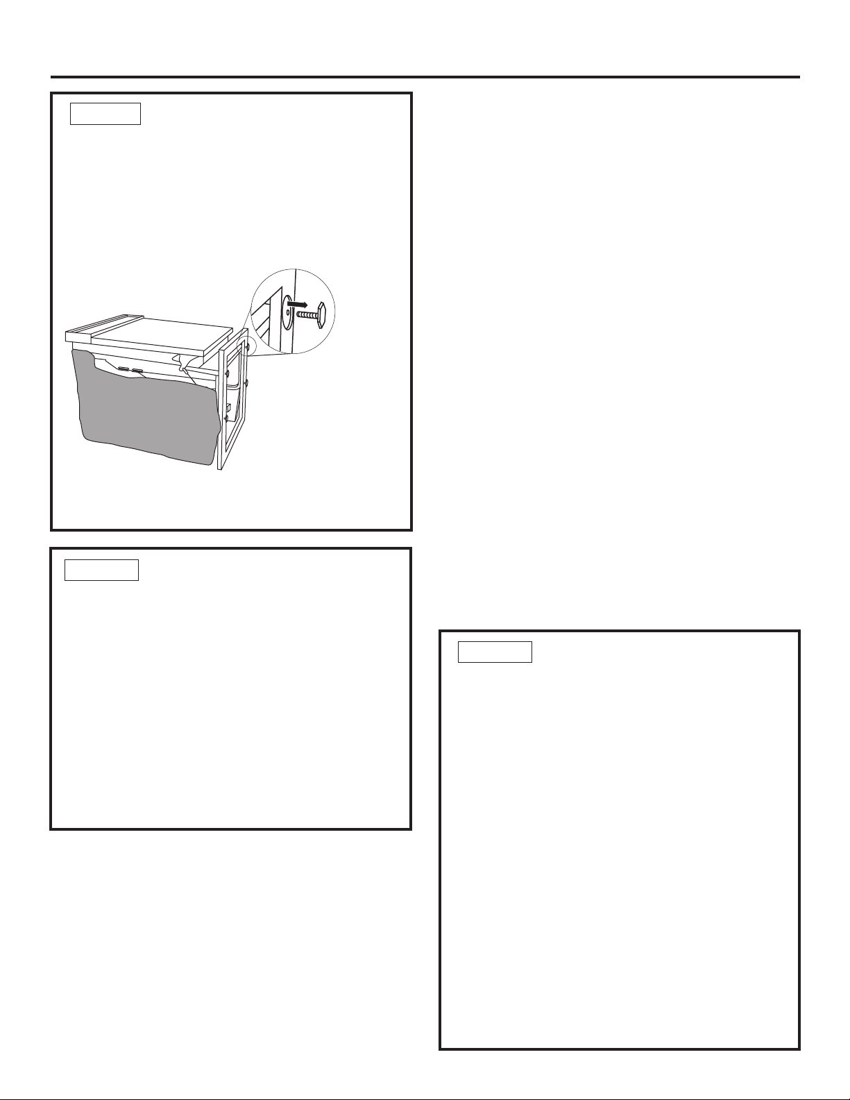
STEP 6 INSTALL ASSEMBLED PANEL
• Secure the panel to the door by inserting the
top and bottom mounting screws with spacers
into the matching keyhole slots.
• Make sure all 4 spacers engage the keyhole
slots.
• Press the panel against the door and push
downwards until the spacers are fully engaged
into the key hole slots. The panel should align
evenly with the top and sides.
• Stand the dishwasher upright.
• Open dishwasher door and drive the supplied
#8 x 1-3/4" truss head screws. Drive one screw
at the top and one on each side as shown,
through the inner door and into the custom
panel.
WARNING: Do not overtighten screws.
Excessive tightening of the screws could damage
door edges.
STEP 7 INSTALL DOOR SPRINGS
The dishwasher is shipped from the factory with a
temporary set of balance springs. Use the heavy
duty springs provided to balance the door after
the custom panel is installed onto the dishwasher.
The door balance system is designed to accommodate a wide variety of custom panels. Use the
holes on the cable to make major adjustments.
Use the holes in the leg for minor adjustments to
the door balance.
• With the dishwasher on the wood skid, close
and latch the door.
• Remove and discard both door springs.
• Attach the new heavy duty door springs. Engage
the end with the short hook into the support
leg and the long hook into the cable.
• Open and close the door.
• If the door drops open when released, increase
spring tension. If the door closes when released, decrease tension.
Screws Must
Be Countersunk
Into Panel
Custom
Door Panel
Dishwasher
Door
Custom
Panel
Note: To increase tension, move spring up one
hole. To decrease tension use lower hole. Adjust
one or both springs until door is correctly
balanced.
Pulley
Shoulder
Check Spring
Cable Routing
IMPORTANT: If the door does not open easily or
falls too quickly, check spring cable routing. The
cable is held in place by “shoulders” on the pulley.
Check to be sure the cable has not slipped over the
pulley shoulders.
Make Minor
Spring Tension
Adjustment Here
4-1/2" Max.
Handle
Custom
Panel
Shoulder Washers
Engage Keyhole
From Top
of Panel
Slots
INCREASE
DECREASE
Adjust Here
to Increase or
Decrease Spring
Tensi on
25-9/16"
Drill 3/32"
Pilot Hole
3/32" Deep
Drill 3/32"
Pilot Hole
3/32" Deep
Trim Around Dotted Line
Pub. No. 31-30558
Dwg. No. 206C1559P098
N.D. 694 3/03
Trim Around Dotted Line
Drill 3/32"
Pilot Hole
3/32" Deep
Page 15
Specification Created 7/03
250202
TM
PDW9700JII – GE Profile™Fully Integrated Built-In Dishwasher
T
I
M
E
R
E
M
A
I
N
I
N
G
 Loading...