

Page 1

We bring good things to life.
2-9296
Caller ID Telephone
User’s Guide
Page 2

2
IMPORTANT INFORMATION
NOTICE: The Industry Canada label identifies certified equipment. This certification means
that the equipment meets certain telecommunications network protective, operational and
safety requirements. The Industry Canada does not guarantee the equipment will operate to
the user’s satisfaction.
Before installing this equipment, users should ensure that it is permissible to be connected to
the facilities of the local telecommunications company. The equipment must also be installed
using an acceptable method of connection. The customer should be aware that compliance with
the above conditions may not prevent degradation of service in some situations.
Repairs to certified equipment should be made by an authorized Canadian maintenance
facility designated by the supplier. Any repairs or alterations made by the user to this
equipment, or equipment malfunctions, may give the telecommunications company cause to
request the user to disconnect the equipment.
Users should ensure for their own protection that the electrical ground connections of the
power utility, telephone lines and internal metallic water pipe systems, if present, are
connected together. This precaution may be particularly important in rural areas.
CAUTION: Users should not attempt to make such connections themselves, but should
contact the appropriate electric inspection authority, or electrician, as appropriate.
NOTES: This equipment may not be used on coin service provided by the telephone company.
Party lines are subject to telephone company tariffs and, therefore, you may not be able to
use your own telephone equipment if you are on a party line. Check with your local
telephone company.
HEARING AID COMPATIBILITY
This telephone system meets FCC/Industry Canada standards for Hearing Aid Compatibility.
INDUSTRY CANADA NUMBER IS LOCATED ON THE CABINET BOTTOM
REN NUMBER IS LOCATED ON THE CABINET BOTTOM
Page 3

3
INTRODUCTION
Your GE 2-9296 Caller ID Telephone is designed to give you flexibility in
use and high quality performance. To get the most from your new Caller ID
Telephone, we suggest that you take a few minutes right now to read
through this instruction manual.
TABLE OF CONTENTS
WARNING:
TO PREVENT FIRE
OR ELECTRICAL SHOCK HAZARD,
DO NOT EXPOSE THIS PRODUCT
TO RAIN OR MOISTURE.
SEE MARKING ON BOTTOM / BACK OF PRODUCT
CAUTION
RISK OF ELECTRIC SHOCK
DO NOT OPEN
THE EXCLAMATION
POINT WITHIN THE
TRIANGLE IS A
WARNING SIGN
ALERTING YOU OF
IMPORTANT
INSTRUCTIONS
ACCOMPANYING
THE PRODUCT.
THE LIGHTNING
FLASH AND ARROWHEAD WITHIN THE
TRIANGLE IS A
WARNING SIGN
ALERTING YOU OF
"DANGEROUS
VOLTAGE" INSIDE
THE PRODUCT.
CAUTION: TO REDUCE THE
RISK OF ELECTRIC SHOCK,
DO NOT REMOVE COVER
(OR BACK). NO USERSERVICEABLE PARTS INSIDE. REFER SERVICING
TO QUALIFIED SERVICE
PERSONNEL.
GETTING STARTED ................................ 4
B
EFORE YOU BEGIN .......................... 4
M
ODULAR JACK REQUIREMENTS ......... 4
POWERING UP ...................................... 5
B
ATTERY INSTALLATION ...................... 5
I
NSTALLATION ....................................... 6
WALL MOUNT INSTALLATION .............. 7
T
ELEPHONE OPERATION ......................... 8
S
ETTING RINGER VOLUME .................. 8
TEMPORARY TONE FEATURE ............... 8
F
LASH BUTTON ................................ 9
R
EDIAL BUTTON ............................... 9
MEMORY DIALING ........................... 10
S
TORING A NUMBER IN MEMORY ...... 10
A
DDING A PAUSE TO THE DIALING
SEQUENCE ................................. 10
C
HANGING A STORED NUMBER ......... 11
D
IALING A NUMBER FROM MEMORY .. 11
DIALING THE EMERGENCY QUICK DIAL
NUMBERS .................................. 11
C
HOOSING A LANGUAGE .................. 12
S
UMMARY SCREEN ......................... 12
RECEIVING AND STORING CALLS ........ 13
VERY IMPORTANT: This product
requires a subscription to Caller ID
service from your telephone
company.
C
ALLER ID OPERATION ........................ 12
NUMBER ONLY SERVICE ................... 13
N
AME AND NUMBER SERVICE ........... 13
SPECIAL CALLER ID MESSAGES ........ 14
C
ALLER ID BUTTONS ....................... 14
N
EW CALL INDICATOR ................... 14
R
EVIEW BUTTONS ........................ 15
DELETE BUTTON ......................... 15
M
ESSAGE INDICATORS ......................... 16
T
ROUBLESHOOTING TIPS ................. 17/18
GENERAL PRODUCT CARE .................... 18
R
EN NUMBER .................................... 19
T
ELEPHONE NETWORK INFORMATION ...... 19
INTERFERENCE INFORMATION ................. 19
I
NDEX ............................................... 20
S
ERVICE ............................................ 21
D
ISPLAY ............................................ 13
Page 4

4
GETTING STARTED
Make sure your package contains the following items:
Base
Handset
BEFORE YOU BEGIN
MODULAR JACK REQUIREMENTS
You need an RJ11(CA11A) type modular jack, which
is the most common type of phone jack and might
look like the one pictured here. If you don’t have a
modular jack, call your local phone company to find
out how to get one installed.
Telephone line cord
Short Telephone line cord
Handset cord
EMERGENCY QUICK DIAL
A
2
ABC3DEF
6
MNO
5
JKL4GHI
9
WXY
8
TUV7PRS
0
OPER
#
FLASH STOR E MEM DIAL REDIAL
PULSE TONEHI LO OFF
BC
1
REVIEW
Page 5

5
BATTERY INSTALLATION
You must use a 9V battery (not
included) in order for the phone to
function. When you install the
battery, be sure to disconnect the
telephone line cords from the back
of the unit.
1. Use a screwdriver or other flat
tool to open the battery compartment door.
2. Insert a fresh, 9-volt alkaline
battery.
3. Close the battery compartment
door securely.
POWERING UP
NOTE: If the LOW BATT message appears in the display, you need to replace
the 9V battery.
Page 6
6
INSTALLATION
Before you begin, see page 5 for
Battery Installation information.
1. Plug one end of the telephone
line cord into the jack marked
PHONE LINE on the back of the
unit, and plug the other end into
a modular wall jack.
2. Connect the handset cord into
the phone jack, on the left side of
the base unit and into the
handset.
3. Set the PULSE/TONE switch
(located on the handset) to TONE
if you have touch-tone service,
or to PULSE if you have rotary
dial service.
0
OPER
#
FLASH STORE MEM DIAL REDIAL
PULSE TONEHI LO OFF
1
2
3
Page 7
7
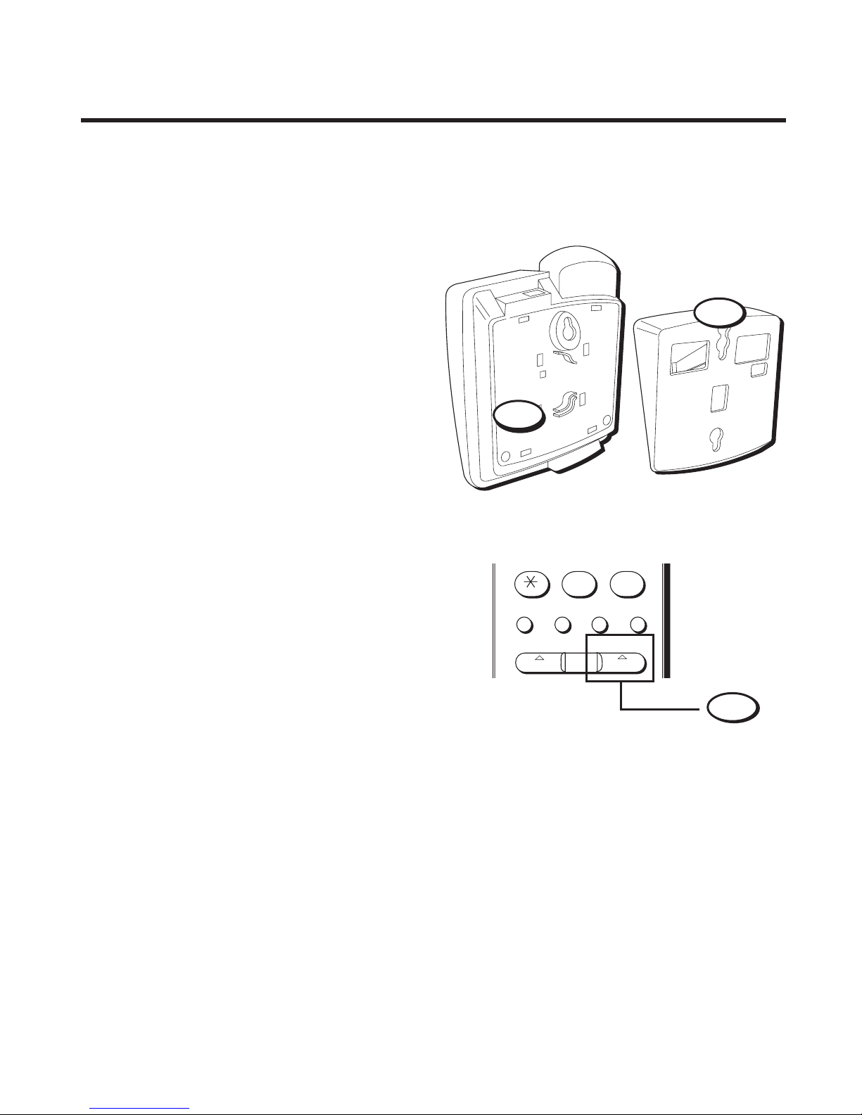
1. Remove the base plate from the
back by placing thumb and fore
finger in the holes and squeezing
before lifting it off.
2. Connect the short telephone line
cord to the unit, and thread it
through the base plate.
3. Reverse the direction of the base
plate and replace it by putting
the tabs into the slots on the top
of the unit first, and then snapping the bottom tabs into place.
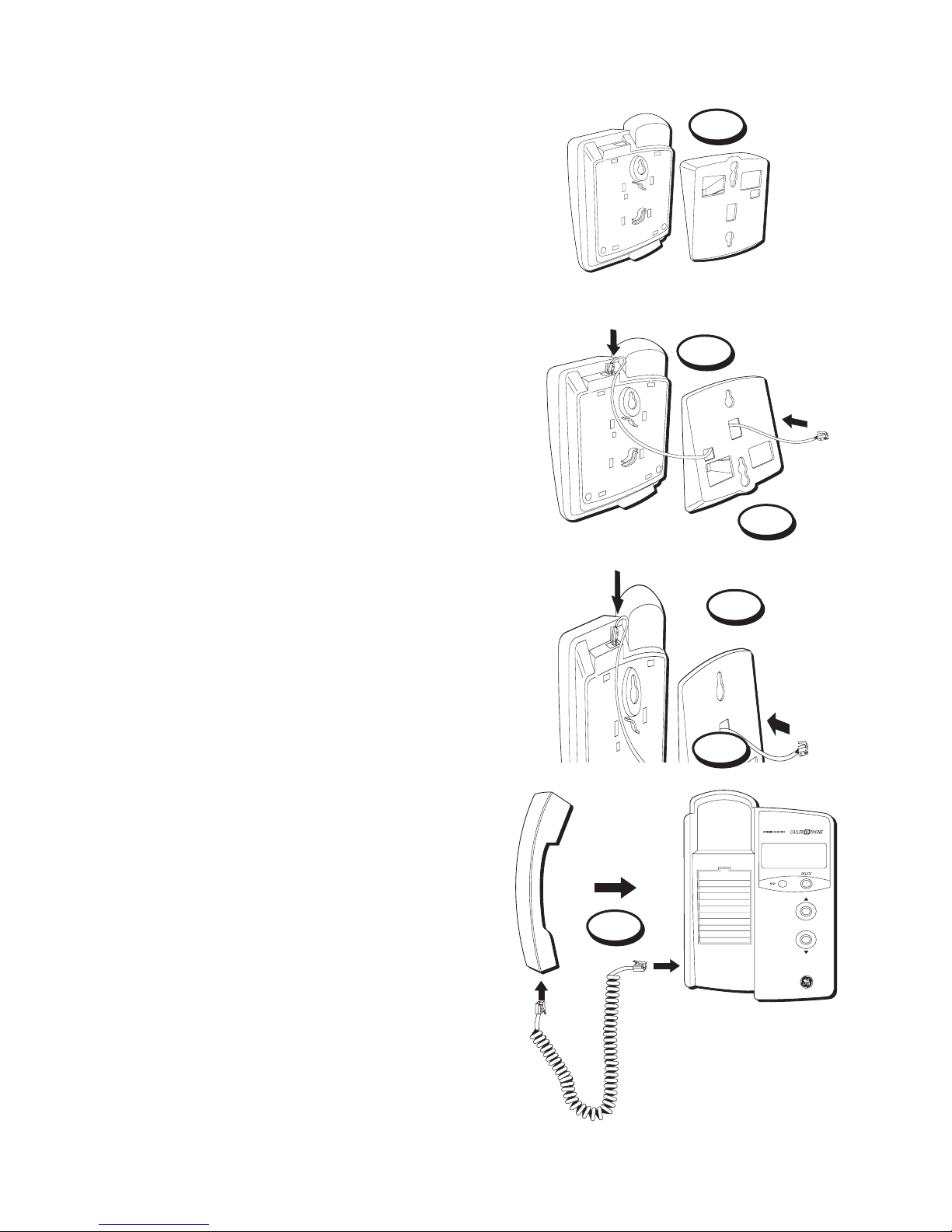
4. Connect the short telephone line
cord into the modular jack on the
wall.
5. Slip the mounting holes over the
wall plate posts and slide the unit
down firmly into place. (Wall
plate not included.)
6. Plug the handset cord into the
handset and into the unit, and
then hang up the handset.
7. Set the PULSE/TONE switch
(located on the handset) to TONE
if you have touch-tone service, or
to PULSE if you have rotary dial
service.
Before you begin see page 5 for
Battery Installation information.
3
1
2
4
5
6
WALL MOUNT INSTALLATION
REVIEW
Page 8

8
TELEPHONE OPERATION
SETTING RINGER VOLUME
The ringer volume switch is located on
the handset. Set it to HI, LO, or OFF.
Remember that the RINGER switch
must be set to HI or LO or the phone will
not ring for incoming calls.
TEMPORARY TONE
FEATURE
Use the Temporary Tone feature if you
have Pulse (rotary) service, and want
to access custom calling services that
require touch-tone dialing, such as
getting information from a local bank
or credit card company.
1. Dial the number for the custom
calling service.
2. Press button after you have
connected to the service to enable
touch-tone dialing.
3. When you hang up, the phone
automatically returns to Pulse
dialing mode.
EMERGENCY QUICK DIAL
A
2
ABC
3
DEF
6
MNO
5
JKL
4
GHI
9
WXY
8
TUV
7
PRS
0
OPER
#
FLASH STORE MEM DIAL REDIAL
PULSE TONEHI LO OFF
BC
1
Ringer volume switch
Page 9

9
EMERGENCY QUICK DIAL
A
2
ABC
3
DEF
6
MNO
5
JKL
4
GHI
9
WXY
8
TUV
7
PRS
0
OPER
#
FLASH STORE MEM DIAL REDIAL
PULSE TONEHI LO OFF
BC
1
Flash button
Redial button
FLASH BUTTON
Press the FLASH button instead of
using the hook switch to activate
custom calling services such as call
waiting or call transfer, which may
be provided by your local phone
company.
REDIAL BUTTON
Redial the last number you called
by pressing the REDIAL button after
you get a dial tone.
The Redial feature holds in memory
the last phone number you dialed
manually. If you pressed any
numbers after dialing the phone
number, (for example, when
accessing a voice-menu system)
those numbers also are redialed.
NOTE: To redial a number stored
in memory, you must press the
MEM DIAL button followed by the
memory location.
Page 10

10
Store as many as 12 numbers in memory for easy dialing. Three can
be stored in the Emergency Quick Dial locations, and nine additional
numbers can be stored in the numbered keys (1-9).
EMERGENCY QUICK DIAL
A
2
ABC
3
DEF
6
MNO
5
JKL
4
GHI
9
WXY
8
TUV
7
PRS
0
OPER
#
BC
1
MEMORY DIALING
STORING A NUMBER IN
MEMORY
1. Pick up the handset.
2. Press the STORE button.
3. Dial the number to be stored.
4. Press the STORE button.
5. Press a memory location (1-9 on
the keypad), or an EMERGENCY
QUICK DIAL button (A, B, or C).
6. Hang up the handset.
ADDING A PAUSE TO THE DIALING SEQUENCE
Use the REDIAL button to insert a delay in the dialing sequence when storing
a number, for example, when you need to dial 9 to get an outside line.
Press REDIAL at the point in the dialing sequence in which a pause is
required:
1. Pick up the handset.
2. Press STORE.
3. Press 9.
4. Press REDIAL to add a pause, and then dial the number.
5. Press STORE.
6. Press an EMERGENCY QUICK DIAL button, or press MEM DIAL
followed by a memory location (1-9 on the keypad).
Page 11

11
CHANGING A STORED NUMBER
Change a stored number by replacing it with a different number.
DIALING A NUMBER FROM MEMORY
You can dial numbers from memory when using the handset. When you
get a dial tone, press the MEM DIAL button followed by the memory
location (1-9) for the number you want to dial.
1. Pick up the handset.
2. Press an emergency quick dial button (A, B, or C).
or
3. Press MEM DIAL, followed by a memory location (1-9 on the keypad).
DIALING THE EMERGENCY QUICK DIAL NUMBERS
To dial emergency quick dial number, just press (A, B, or C).
IMPORTANT: If you make test calls to emergency numbers, remain on the
line and explain the reason for the call. Also, make these calls in off-peak
hours, such as early morning or late evening.
Page 12

12
REVIEW
CALLER ID OPERATION
CHOOSING A LANGUAGE
This unit can display the message
indicators in English, Spanish, or
French. When you first power up
your Caller ID unit
ENGLISH
appears in the display. To select the
language:
1. Press and hold DELETE.
2. Press REVIEW.
3. Release DELETE.
4. Press REVIEW to scroll
through the options.
5. Press DELETE once to confirm
your selection.
SUMMARY SCREEN
The Summary Screen shows the
current time, current date and
number of new calls to be reviewed. The Summary Screen is
displayed until any button is
pressed or until 30 seconds after a
new call has been received.
NOTE: The number of new calls
will be reset to ZERO after any new
calls have been reviewed.
VERY IMPORTANT: This
product requires a subscription
to Caller ID service from your
telephone company.
NOTE: Check with your
local phone company
regarding name service
availability.
NEW CALL
indicator
DOWN
button
UP
button
DELETE
button
Page 13

13
DISPLAY
NUMBER ONLY SERVICE
• This display shows an example
of number only service.
RECEIVING AND STORING CALLS
This unit receives and displays information transmitted
by your local phone company. This information can include the phone
number, date, and time; or the name, phone number, date, and time.
The unit can store up to 95 calls for later review. When the memory is full,
a new call automatically replaces the oldest call in memory.
NAME AND NUMBER
SERVICE
* Caller's name is sent by your
telephone company, if available.
NOTE: Press the REVIEW button to
view the caller's number.
NOTE: Check with your local phone
company regarding name service
availability.
time of call
date of call
number of
call(s)
number of caller
12:11
PM 2/12 84
317-555-1212
CALL
#
Page 14

14
SPECIAL CALLER ID MESSAGES
• PRIVATE CALL — The calling
party has prevented their number
and/or name from being sent.
• OUT OF AREA — The calling
number information is not
available, or was sent from a
location not served by Caller ID
service.
CALLER ID BUTTONS
NEW CALL INDICATOR
When calls are received but have
not been reviewed, the New Call
indicator flashes until any unread
calls are reviewed.
- PRIVATE -
- OUT OF AREA -
Page 15

15
REVIEW
REVIEW BUTTONS
• Press REVIEW to see the next
record. When all messages have
been viewed,
END OF LIST
appears in the display.
• Press REVIEW to view previous records.
DELETE BUTTON
• Press DELETE twice to permanently delete the record shown
in the display.
• Press and hold DELETE for at
least six second, or until NO
CALLS appears in the display, to
delete information about all calls.
NEW CALL
indicator
DOWN
button
UP
button
DELETE
button
Page 16

16
MESSAGE INDICATORS
The following special messages indicate the status of a message or the
unit:
NO CALLS The caller memory is empty.
OUT OF AREA The incoming call does not have Caller ID service
or their service area is not linked to yours. If
OUT
OF AREA
appears along with a calling number,
the name information for that number was not
available.
LOW BATT Battery power level is low.
PRIVATE CALL The caller of the incoming call is registered as
“Private Number."
LINE ERROR Caller information has been interrupted during
transmission.
END OF LIST There are no additional calls to review.
NEW CALLS The number of unreviewed calls.
MESSAGE WAITING Indicates unreviewed message(s).
Page 17

17
TROUBLESHOOTING TIPS
TELEPHONE
Problem Solution
No dial tone. • Check hook switch to make
Won't dial out sure it pops up.
• Make sure TONE/PULSE is set to correct
position.
• Unplug the phone, wait 30 seconds, and
plug the phone back in.
Phone doesn’t ring • Check RINGER VOLUME.
• Could have too many phones on one line.
(See FCC registration information regarding
REN).
Light and tone • This is normal as power is fluctuating
feedback flutter when with phone outpulsing.
dialing in PULSE mode.
Can’t be heard by • Make sure coiled phone cord is securely
other party plugged in
.
• Make sure other phones are not OFF hook at
the same time. If so, this is normal condition
as volume drops when additional phones are
used at once.
Memory dialing • Make sure you entered numbers correctly.
(See "Memory Dialing.")
Page 18

18
GENERAL PRODUCT CARE
To keep your Caller ID phone working and looking good, follow these guidelines:
• Avoid putting it near heating appliances and devices that generate
electrical noise (for example, motors or fluorescent lamps).
• DO NOT expose to direct sunlight or moisture.
• Avoid dropping and other rough treatment of the unit.
• Clean with a soft cloth.
• Never use a strong cleaning agent or abrasive powder because this will
damage the finish.
• Retain the original packaging in case you need to ship it at a later date.
TROUBLESHOOTING TIPS
CALLER ID
Problem Solution
No Display • If you are using battery power, this is a normal
condition unless you press a button or the
phone is receiving a call.
Incoming calls • Did you order Caller ID service from your local
telephone company? This unit requires that
you subscribe to Caller ID service in
order to work.
LINE ERROR Message • The unit displays this message if it detects
anything other than valid Caller ID information
during the silent period after the first ring.
This message indicates either the presence of
noises on the line, or that an invalid message
has been sent from the telephone company.
are not displayed.
is Displayed
Page 19

19
REN NUMBER
On the bottom of this equipment is a label indicating, among other information, the
FCC Registration number and Ringer Equivalence Number (REN) for the equipment.
You must, upon request, provide this information to your telephone company.
The REN is useful in determining the number of devices you may connect to your
telephone line and still have all of these devices ring when your telephone number
is called. In most (but not all) areas, the sum of the RENs of all devices connected
to one line should not exceed 5. To be certain of the number of devices you may
connect to your line as determined by the REN, you should contact your local
telephone company.
TELEPHONE NETWORK INFORMATION
Should your equipment cause trouble on your line which may harm the telephone
network, the telephone company, where practicable, may notify you that temporary
discontinuance of service may be required. Where prior notice is not practicable and
the circumstances warrant such action, the telephone company may temporarily
discontinue service immediately.
The telephone company may make changes in its communications facilities,
equipment, operations or procedures where such action is required in the operation
of its business. If these changes are expected to affect the use or performance of
your telephone equipment, the telephone company will likely give you adequate
notice to allow you to maintain uninterrupted service.
Notice must be given to the telephone company upon termination of your telephone
from your line.
INTERFERENCE INFORMATION
This Class B digital apparatus meets all requirements of the Canadian InterferenceCausing Equipment Regulations.
This equipment generates and uses radio frequency energy which may interfere
with residential radio and television reception if not properly installed and used in
accordance with instructions contained in this manual. Reasonable protection
against such interference is ensured, although there is no guarantee this will not
occur in a given installation. If interference is suspected and verified by switching
this equipment on and off, the user is encouraged to try to correct the interference
by one or more of the following measures: Reorient the radio/television receiver’s
antenna, relocate the equipment with respect to the receiver, plug the equipment
and receiver into separate circuit outlets. The user may also wish to consult a
qualified radio/television technician for additional suggestions. This equipment has
been fully tested and complies with all limits for Class B computing devices
pursuant to part 15, Sub-part J, FCC Rules and Regulations.
Page 20

20
INDEX
A
Adding a Pause to the
Dialing Sequence 10
B
Battery Installation 5
C
Caller ID 18
Caller ID Buttons 14
Caller ID Operation 12
Changing a Stored
Number 11
Choosing a Language 12
D
Delete Button 15
Dialing a Number from
Memory 11
Dialing the Emergency
Quick Dial Numbers
11
Displays 13
E
END OF LIST 16
F
Flash Button 9
G
General Product Care 18
Getting Started 4
H
Hearing Aid Compatibility
2
I
Installation 6
Important Information 2
L
LINE ERROR 16
LOW BATT 16
M
Memory Dialing 10
Message Indicators 16
MESSAGE WAITING 16
Modular Jack Require-
ments 4
N
Name and Number
Service 13
New call Indicator 14
NEW CALLS 16
NO CALLS 16
Number Only Service 13
O
OUT OF AREA 16
P
Powering Up 5
PRIVATE CALL 16
R
Receiving and Storing
Calls 13
Redial Button 9
Review Buttons 15
S
Service 21
Setting Ringer Volume 8
Special Caller ID Mes-
sages 14
Storing a Number in
Memory 10
Summary Screen 12
T
Telephone 17
Telephone Operation 8
Temporary Tone Feature
8
Troubleshooting Tips 17
W
Wall Mount Installation 7
Page 21

21
SERVICE
Thomson Consumer Electronics Canada, Inc. warrants to the purchaser or gift
recipient that if any manufacturing defect becomes apparent in this product within
1 year from the original date of purchase, it will be replaced free of charge,
including return transportation.
This warranty does not include damage to the product resulting from accidents,
misuse or leaking batteries.
Should your product not perform properly during the warranty period, either:
1. Return it to the selling dealer with proof of purchase for replacement,
OR
2. Remove the batteries (where applicable), and pack product complete with
accessories in the original carton (or equivalent).
— Mail prepaid (with proof of purchase) and insured to:
Thomson Consumer Electronics Canada, Inc.
Distribution Centre
7400 A Bramalea Road
Mississauga, Ontario L5S 1X1
The provisions of this written warranty are in addition to and not a modification of
or subtraction from the statutory warranties and other rights and remedies
contained in any applicable legislation, and to the extent that any such provisions
purport to disclaim, exclude or limit any such statutory warranties and other rights
and remedies, such provisions shall be deemed to be amended to the extent
necessary to comply therewith.
If you are unable to find a qualified servicer for out of warranty service, you may
write to:
Thomson Consumer Electronics Canada, Inc.
P.O. Box 0944
Indianapolis, Indiana, U.S.A., 46206-0944
Attach your sales receipt to this booklet for future reference. This information is
required if service is needed during the warranty period.
PURCHASE DATE _____________________________________
NAME OF STORE______________________________________
Page 22

22
P.O. Box 1976, Indianapolis, IN 46206
© 1998 Thomson Consumer Electronics, Inc.
Trademark(s) ® Registered
Marca(s) Registrada(s)
Model 2-9296
20909360 (Rev. 2 E/F)
98-10
Printed in Philippines
 Loading...