

GE Everest XLG3 VideoProbe Operating Manual

Everest XLG3
To buy, sell, rent or trade-in this product please click on the link below:
http://www.avionteq.com/GE-Everest-XLG3-VideoProbe-NDT-Video-Borescope.aspx
www.avionteq.com
®
™
VideoProbe
System
Operating Manual

ii GE Inspection Technologies XLG3 VideoProbe System
Copyright 2009 GE Inspection Technologies, LP. All rights are reserved. No one is permitted to reproduce or duplicate, in any form,
this manual or any part thereof without permission from GE Inspection Technologies, LP.
Software in this product is copyright GE Inspection Technologies, LP, or its vendors. All rights are reserved. The software is protected
by United States of America copyright and international treaty provisions applicable worldwide. Under such laws, the licensee is
entitled to use the copy of the software incorporated with this instrument as intended in the operation of the product in which it is
embedded. The software may not be copied, decompiled, reverse-engineered, disassembled, or otherwise reduced to humanperceivable form. This is not a sale of the software or any copy of the software; all right, title, and ownership of the software remains
with GE Inspection Technologies, LP, or its vendors.
VideoProbe, ShadowProbe, and StereoProbe are registered trademarks of GE Inspection Technologies, LP. XL PRO, XLG3, iView,
All-Way, QuickChange, and Steer-and-Stay are trademarks of GE Inspection Technologies, LP.
NETGEAR is a registered trademark of NETGEAR, Inc. Firefox is a registered trademark of the Mozilla Foundation.
MPEG Layer-3 audio coding technology licensed from Fraunhofer IIS and Thomson.
GE Inspection Technologies, LP, assumes no responsibility for any injury to anyone, or for any illegal or improper use of the product,
that may result from failure to use this product in accordance with the information published in this manual.
This device complies with Part 15 of the FCC Rules. Operation is subject to the following two conditions: (1) this device may not
cause harmful interference, and (2) this device must accept any interference received, including interference that may cause
undesired operation
FCC Statement
This product has been tested and complies with the specifications for a Class A digital device, pursuant to Part 15 of FCC Rules.
These limits are designed to provide reasonable protection against harmful interference in a residential installation. This equipment
generates, uses, and can radiate radio frequency energy and, if not installed and used according to the instructions, may cause
harmful interference to radio communications. However, there is no guarantee that interference will not occur in a particular
installation. If this equipment does cause harmful interference to radio television reception, which is found by turning the equipment
off and on, the user is encouraged to try to correct the interference by one or more of the following measures:
• Reorient or relocate the receiving antenna
• Increase the separation between the equipment or devices
• Connect the equipment to an outlet other than the receiver's
• Consult a dealer or an experienced radio/lV technician for assistance
FCC Radiation Exposure Statement
This equipment complies with FCC radiation exposure limits set forth for an uncontrolled environment. This equipment should be
installed and operated with minimum distance 20 cm between the radiator and your body.
Safety Notices
Caution: To reduce the risk of fire, use only No.26 AWG or larger telecommunication line cord.
Do not use this product near water, for example. in a wet basement or near a swimming pool.

User Manual iii
Contact Information
Service
To obtain service for your system, call one of the service centers below. If the problem
cannot be corrected over the phone, you will be given a Return Materials Authorization
Number (RMA) for shipment to the service center.
Always contact a GE Inspection Technologies service center for an RMA prior to returning
any products for service or repair.
Web Site
USA GE Inspection Technologies
Product Service Dept.
721 Visions Drive
Skaneateles, NY 13152
Germany GE Inspection Technologies GmbH
Lotzenäcker 4
72379 Hechingen
Hong Kong GE Inspection Technologies (HK) Ltd.
Unit 1602, 16/F Sing Pao Building
101 King's Road
North Point
Hong Kong
www.ge.com/inspectiontechnologies
Phone: 888-332-3848
315-554-2000 ext. 1
Fax: 866 899 4184
Phone: +49 7471 98820
Fax: +49 7471 9882 30
Phone: +852 2877 0801
Fax: +852 2877 0868

iv GE Inspection Technologies XLG3 VideoProbe System

Contents
Contact Information . . . . . . . . . . . . . . . . . . . . . . . . . . . . . . . . . . . . . . . iii
1 - Introduction . . . . . . . . . . . . . . . . . . . . . . . . . . . . . . . . . . . . . . . . . . . . . 1
v
About This Manual . . . . . . . . . . . . . . . . . . . . . . . . . . . . . . . . . . . . . . . . . . . . . . . . 1
Getting Help . . . . . . . . . . . . . . . . . . . . . . . . . . . . . . . . . . . . . . . . . . . . . . . . . . . . . 1
System Overview . . . . . . . . . . . . . . . . . . . . . . . . . . . . . . . . . . . . . . . . . . . . . . . . . 2
Frequent Tasks . . . . . . . . . . . . . . . . . . . . . . . . . . . . . . . . . . . . . . . . . . . . . . . . . . . 3
About the Battery . . . . . . . . . . . . . . . . . . . . . . . . . . . . . . . . . . . . . . . . . . . . . . . . . 4
About the Image Processing Package . . . . . . . . . . . . . . . . . . . . . . . . . . . . . . . . . 4
About the Network Package . . . . . . . . . . . . . . . . . . . . . . . . . . . . . . . . . . . . . . . . . 5
About the Menu Directed Inspection Package . . . . . . . . . . . . . . . . . . . . . . . . . . . 6
Controls, Indicators, Connectors, etc.. . . . . . . . . . . . . . . . . . . . . . . . . . . . . . . . . . 7
Navigating the Menus . . . . . . . . . . . . . . . . . . . . . . . . . . . . . . . . . . . . . . . . . . . . . 15
Restoring Factory Defaults . . . . . . . . . . . . . . . . . . . . . . . . . . . . . . . . . . . . . . . . . 16
Safety Information. . . . . . . . . . . . . . . . . . . . . . . . . . . . . . . . . . . . . . . . . . . . . . . . 17
Informations sur la sécurité. . . . . . . . . . . . . . . . . . . . . . . . . . . . . . . . . . . . . . . . . 20
2 - Safe Powering and Grounding. . . . . . . . . . . . . . . . . . . . . . . . . . . . . 23
Overview of Safe Powering and Grounding . . . . . . . . . . . . . . . . . . . . . . . . . . . . 23
Verifying AC Earth Ground Path. . . . . . . . . . . . . . . . . . . . . . . . . . . . . . . . . . . . . 24
Grounding With a DC Source (Battery) . . . . . . . . . . . . . . . . . . . . . . . . . . . . . . . 25
Special Grounding Situations . . . . . . . . . . . . . . . . . . . . . . . . . . . . . . . . . . . . . . . 25
3 - Setting Up and Putting Away the System. . . . . . . . . . . . . . . . . . . . 27
Setting Up the System . . . . . . . . . . . . . . . . . . . . . . . . . . . . . . . . . . . . . . . . . . . . 27
Changing the Probe . . . . . . . . . . . . . . . . . . . . . . . . . . . . . . . . . . . . . . . . . . . . . . 30
Changing the Optical Tip . . . . . . . . . . . . . . . . . . . . . . . . . . . . . . . . . . . . . . . . . . 31
Putting the System Away . . . . . . . . . . . . . . . . . . . . . . . . . . . . . . . . . . . . . . . . . . 32
Communicating to a PC Through a Router or Network . . . . . . . . . . . . . . . . . . . 34
Manual Entry - Wireless Access Point . . . . . . . . . . . . . . . . . . . . . . . . . . . . . . . . 37
4 - Setting Up the Software . . . . . . . . . . . . . . . . . . . . . . . . . . . . . . . . . . 39
Reviewing Settings for Audio . . . . . . . . . . . . . . . . . . . . . . . . . . . . . . . . . . . . . . . 39
Reviewing Settings for Image Format and Quality . . . . . . . . . . . . . . . . . . . . . . . 40
Reviewing the Setting for Video Quality . . . . . . . . . . . . . . . . . . . . . . . . . . . . . . . 41
Reviewing Settings for Text Color. . . . . . . . . . . . . . . . . . . . . . . . . . . . . . . . . . . . 42
Reviewing Settings for a Logo . . . . . . . . . . . . . . . . . . . . . . . . . . . . . . . . . . . . . . 42
Reviewing Settings for Measurement. . . . . . . . . . . . . . . . . . . . . . . . . . . . . . . . . 43
Reviewing Settings for the System . . . . . . . . . . . . . . . . . . . . . . . . . . . . . . . . . . . 44
Reviewing Settings for Communications . . . . . . . . . . . . . . . . . . . . . . . . . . . . . . 45

vi GE Inspection Technologies XLG3 VideoProbe System
5 - Capturing Images and Videos . . . . . . . . . . . . . . . . . . . . . . . . . . . . . 47
Process Overview. . . . . . . . . . . . . . . . . . . . . . . . . . . . . . . . . . . . . . . . . . . . . . . . 47
Steering the Probe . . . . . . . . . . . . . . . . . . . . . . . . . . . . . . . . . . . . . . . . . . . . . . . 49
Freezing an Image . . . . . . . . . . . . . . . . . . . . . . . . . . . . . . . . . . . . . . . . . . . . . . . 50
Working With a Recalled Image . . . . . . . . . . . . . . . . . . . . . . . . . . . . . . . . . . . . . 51
Working With a Split Screen . . . . . . . . . . . . . . . . . . . . . . . . . . . . . . . . . . . . . . . . 52
Adjusting the Brightness. . . . . . . . . . . . . . . . . . . . . . . . . . . . . . . . . . . . . . . . . . . 53
Reducing “Noise” in Dark Images. . . . . . . . . . . . . . . . . . . . . . . . . . . . . . . . . . . . 54
Correcting Wide-Angle Distortion . . . . . . . . . . . . . . . . . . . . . . . . . . . . . . . . . . . . 56
Lengthening Exposure Time. . . . . . . . . . . . . . . . . . . . . . . . . . . . . . . . . . . . . . . . 57
Enhancing Contrast . . . . . . . . . . . . . . . . . . . . . . . . . . . . . . . . . . . . . . . . . . . . . . 58
Zooming . . . . . . . . . . . . . . . . . . . . . . . . . . . . . . . . . . . . . . . . . . . . . . . . . . . . . . . 58
Inverting an Image . . . . . . . . . . . . . . . . . . . . . . . . . . . . . . . . . . . . . . . . . . . . . . . 59
Annotating With Text or Arrows . . . . . . . . . . . . . . . . . . . . . . . . . . . . . . . . . . . . . 60
Saving an Image. . . . . . . . . . . . . . . . . . . . . . . . . . . . . . . . . . . . . . . . . . . . . . . . . 65
Working With Videos . . . . . . . . . . . . . . . . . . . . . . . . . . . . . . . . . . . . . . . . . . . . . 67
6 - Managing Files & Communicating With Other Computers . . . . . . 73
About the Thumbnail Screen . . . . . . . . . . . . . . . . . . . . . . . . . . . . . . . . . . . . . . . 73
Working With Removable Storage Devices . . . . . . . . . . . . . . . . . . . . . . . . . . . . 74
Recalling a File . . . . . . . . . . . . . . . . . . . . . . . . . . . . . . . . . . . . . . . . . . . . . . . . . . 75
Creating, Renaming, or Deleting Folders . . . . . . . . . . . . . . . . . . . . . . . . . . . . . . 75
Copying Files . . . . . . . . . . . . . . . . . . . . . . . . . . . . . . . . . . . . . . . . . . . . . . . . . . . 75
Deleting Files . . . . . . . . . . . . . . . . . . . . . . . . . . . . . . . . . . . . . . . . . . . . . . . . . . . 76
Renaming a File . . . . . . . . . . . . . . . . . . . . . . . . . . . . . . . . . . . . . . . . . . . . . . . . . 76
Archiving (Copying) Files to a DVD . . . . . . . . . . . . . . . . . . . . . . . . . . . . . . . . . . 77
Using the Desktop . . . . . . . . . . . . . . . . . . . . . . . . . . . . . . . . . . . . . . . . . . . . . . . 78
Sharing Files or Live Video With a PC . . . . . . . . . . . . . . . . . . . . . . . . . . . . . . . . 80
7 - Measuring Features and Defects. . . . . . . . . . . . . . . . . . . . . . . . . . . 87
About Measuring. . . . . . . . . . . . . . . . . . . . . . . . . . . . . . . . . . . . . . . . . . . . . . . . . 87
3D Phase Measurements . . . . . . . . . . . . . . . . . . . . . . . . . . . . . . . . . . . . . . . . . . 91
Stereo Measurements. . . . . . . . . . . . . . . . . . . . . . . . . . . . . . . . . . . . . . . . . . . . . 96
Shadow Measurements . . . . . . . . . . . . . . . . . . . . . . . . . . . . . . . . . . . . . . . . . . 104
Comparison Measurements . . . . . . . . . . . . . . . . . . . . . . . . . . . . . . . . . . . . . . . 110
Verifying Measurement Tips . . . . . . . . . . . . . . . . . . . . . . . . . . . . . . . . . . . . . . . 112
Troubleshooting Measurements . . . . . . . . . . . . . . . . . . . . . . . . . . . . . . . . . . . . 113
8 - Maintenance . . . . . . . . . . . . . . . . . . . . . . . . . . . . . . . . . . . . . . . . . . 115
Inspecting and Cleaning the System . . . . . . . . . . . . . . . . . . . . . . . . . . . . . . . . 115
Replacing the Lamp . . . . . . . . . . . . . . . . . . . . . . . . . . . . . . . . . . . . . . . . . . . . . 118
Checking and Replacing the Fuses . . . . . . . . . . . . . . . . . . . . . . . . . . . . . . . . . 120
Maintaining the Battery. . . . . . . . . . . . . . . . . . . . . . . . . . . . . . . . . . . . . . . . . . . 122
Replacing the Internal Memory Card . . . . . . . . . . . . . . . . . . . . . . . . . . . . . . . . 125

User Manual vii
9 - Troubleshooting . . . . . . . . . . . . . . . . . . . . . . . . . . . . . . . . . . . . . . . 127
Image . . . . . . . . . . . . . . . . . . . . . . . . . . . . . . . . . . . . . . . . . . . . . . . . . . . . . . . . 127
Probe . . . . . . . . . . . . . . . . . . . . . . . . . . . . . . . . . . . . . . . . . . . . . . . . . . . . . . . . 128
Power . . . . . . . . . . . . . . . . . . . . . . . . . . . . . . . . . . . . . . . . . . . . . . . . . . . . . . . . 128
Lamp. . . . . . . . . . . . . . . . . . . . . . . . . . . . . . . . . . . . . . . . . . . . . . . . . . . . . . . . . 128
Software . . . . . . . . . . . . . . . . . . . . . . . . . . . . . . . . . . . . . . . . . . . . . . . . . . . . . . 129
DVD Recording. . . . . . . . . . . . . . . . . . . . . . . . . . . . . . . . . . . . . . . . . . . . . . . . . 129
Storing Data to USB Thumb Drive . . . . . . . . . . . . . . . . . . . . . . . . . . . . . . . . . . 129
A - Specifications . . . . . . . . . . . . . . . . . . . . . . . . . . . . . . . . . . . . . . . . . 131
B - Agency Certifications. . . . . . . . . . . . . . . . . . . . . . . . . . . . . . . . . . . 135
C - Chemical Compatibility . . . . . . . . . . . . . . . . . . . . . . . . . . . . . . . . . 137
D - Warranty . . . . . . . . . . . . . . . . . . . . . . . . . . . . . . . . . . . . . . . . . . . . . 139
E - Menu Trees . . . . . . . . . . . . . . . . . . . . . . . . . . . . . . . . . . . . . . . . . . . 141
F - Optical Tips . . . . . . . . . . . . . . . . . . . . . . . . . . . . . . . . . . . . . . . . . . . 147
6.2mm Internal Working Channel Feature . . . . . . . . . . . . . . . . . . . . . . . . . . . . 150
G - Environmental Compliance . . . . . . . . . . . . . . . . . . . . . . . . . . . . . . 151
Index . . . . . . . . . . . . . . . . . . . . . . . . . . . . . . . . . . . . . . . . . . . . . . . . . . . 153

viii GE Inspection Technologies XLG3 VideoProbe System

1
1
Introduction
About This Manual. . . . . . . . . . . . . . . . . . . . . . . . . . . . . . . . . . . . . . . . . . . . . . . . .1
Getting Help. . . . . . . . . . . . . . . . . . . . . . . . . . . . . . . . . . . . . . . . . . . . . . . . . . . . . . 1
System Overview. . . . . . . . . . . . . . . . . . . . . . . . . . . . . . . . . . . . . . . . . . . . . . . . . . 2
Frequent Tasks . . . . . . . . . . . . . . . . . . . . . . . . . . . . . . . . . . . . . . . . . . . . . . . . . . . 3
About the Battery. . . . . . . . . . . . . . . . . . . . . . . . . . . . . . . . . . . . . . . . . . . . . . . . . .4
About the Image Processing Package . . . . . . . . . . . . . . . . . . . . . . . . . . . . . . . . .4
About the Network Package . . . . . . . . . . . . . . . . . . . . . . . . . . . . . . . . . . . . . . . . . 5
About the Menu Directed Inspection Package . . . . . . . . . . . . . . . . . . . . . . . . . . . 6
Controls, Indicators, Connectors, etc. . . . . . . . . . . . . . . . . . . . . . . . . . . . . . . . . . . 7
Navigating the Menus . . . . . . . . . . . . . . . . . . . . . . . . . . . . . . . . . . . . . . . . . . . . . 15
Safety Information . . . . . . . . . . . . . . . . . . . . . . . . . . . . . . . . . . . . . . . . . . . . . . . . 17
Informations sur la sécurité . . . . . . . . . . . . . . . . . . . . . . . . . . . . . . . . . . . . . . . . .20
About This Manual
This manual is written for visual inspection technicians who have a basic understanding of
inspection principles and practices, and who are familiar with basic computer operations
(such as using a mouse and managing electronic files and folders), but who may not have
experience with a video borescope.
The manual provides a product overview, step-by-step procedures, and reference
information. It does not include repair information.
To ensure operator safety, read and understand this manual before using the system.
Getting Help
Beyond this manual you can get product help in several ways:
• Training
• Phone
Introductory in-person training is free with your system purchase. Additional training is
available for a fee. Contact GE Inspection Technologies.
For phone numbers, see “Service” on page iii.
2 Chapter 1 Introduction GE Inspection Technologies XLG3 VideoProbe System
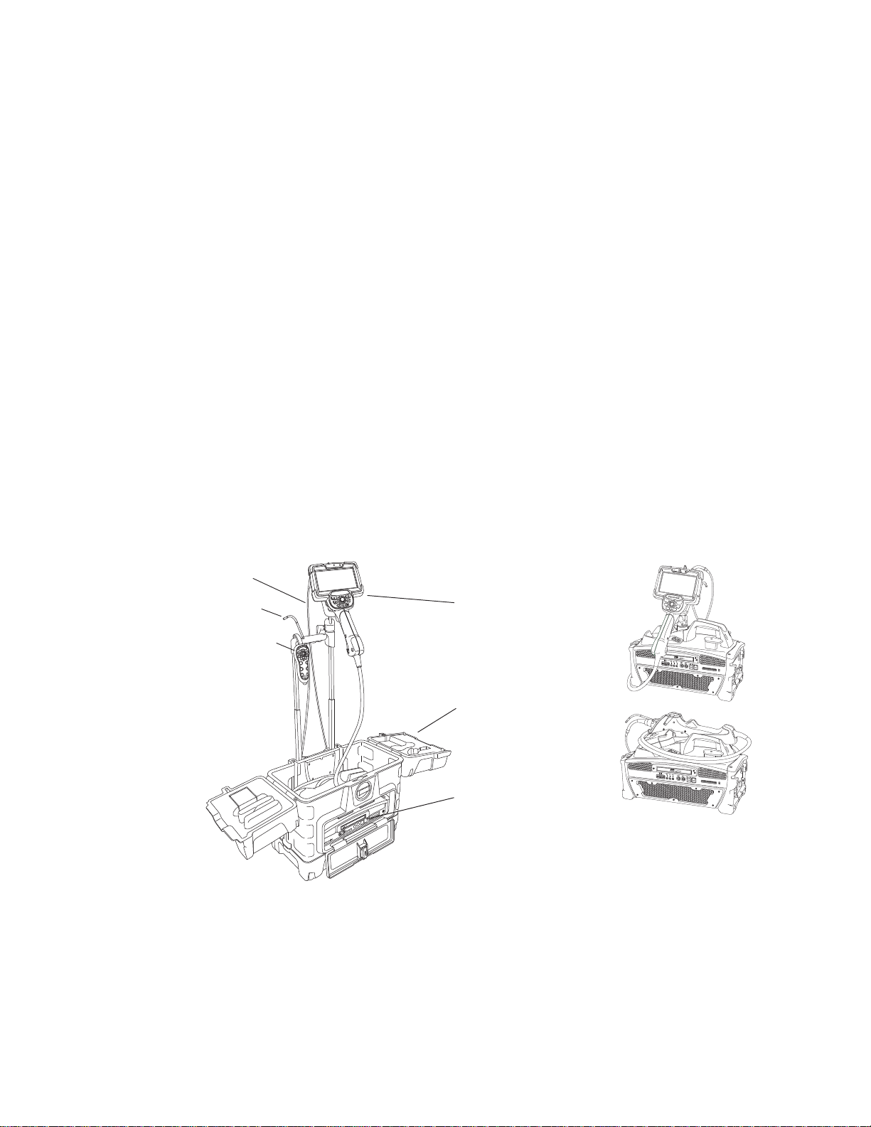
Case
(small size shown)
Base unit
(accessible when
case door is open,
as shown)
Handset
Probe
Base unit removed from case:
two positions for handset
Camera
Remote control
System Overview
The rugged and dependable Everest XLG3™ VideoProbe® system is an advanced videobased flexible borescope used for remote visual inspection.
Working through access passages, the XLG3 system delivers high-resolution images of
internal details of turbine engines, airframes, automotive engines, piping, vessels, windturbine gear boxes, underwater structures, etc.
The probe’s fiberoptic bundle illuminates the inspection area with light generated by a
75-watt high-intensity discharge (HID) arc lamp in the base unit. At the end of the probe, a
miniature camera assembly converts the image into an electronic image, and sends it
back through the probe. The system displays the image on the handset. No focusing is
required, because the XLG3 system contains a fixed-focus optical system with a large
depth of field.
If your system is equipped with measurement capability, you can measure defects and
features.
The XLG3 system is compatible with various removable storage devices: DVD-R, DVD+R,
compact Flash cards (Type 1), USB thumb drives, portable drives — most compatible
USB-based or compact Flash card-based devices.
With our QuickChange™ interchangeable probes, you can quickly reconfigure the system
for maximum productivity.
E
G
es
i
og
l
no
h
ec
T
on
ti
ec
p
s
n
I
Everest XLG3
3
G
erest XL
Ev

User Manual Chapter 1 Introduction 3
Frequent Tasks
Setting Up the System — Summary
For details, see “Setting Up the System” on page 27.
1. Open case’s lids and front door.
2. Verify safe powering and grounding.
Inspect ground prong on power cord.
3. Connect to AC power, or attach battery.
4. Turn on power switch.
5. Remove insertion tube from storage reel.
6. Unwrap handset cable, and remove handset from case.
7. Install optical tip, accessories, and peripheral devices.
Capturing Images — Summary
For details, see “Capturing Images and Videos” on page 47.
1. Steer probe until desired view is displayed.
Position camera by moving joystick toward desired feature.
2. Freeze the image.
When desired image is displayed, press .
3. Save the image.
Press . Select Return. The image is saved.
Recording Video — Summary
For details, see “Working With Videos” on page 67.
1. Start recording video.
Press . Select Start Recording.
2. Stop recording video.
Press . Select Video Record > Stop Recording.
Putting the System Away — Summary
For details, see “Putting the System Away” on page 32.
1. Straighten bending neck.
2. Turn off system, and disconnect from power source.
3. Detach peripheral devices and accessories.
4. Return insertion tube to storage reel, and wrap handset cable.
5. Store system and components in case.
4 Chapter 1 Introduction GE Inspection Technologies XLG3 VideoProbe System
About the Battery
Batteries for the XLG3 system are optional. Two sizes are available: one-hour and
two-hour.
To learn about removing, charging, or installing the battery, see “Maintaining the Battery”
on page 122.
Battery (one-hour size shown)
About the Image Processing Package
The image processing package — which lets you enhance images under particular
circumstances — includes the following features.
Feature Description Details
Distortion correction Flattens image edges when you use a
120° optical tip.
Adaptive noise reduction Sharpens images when the probe is in a
dark area.
“Correcting Wide-Angle Distortion” on
page 56
“Reducing “Noise” in Dark Images” on
page 54
User Manual Chapter 1 Introduction 5
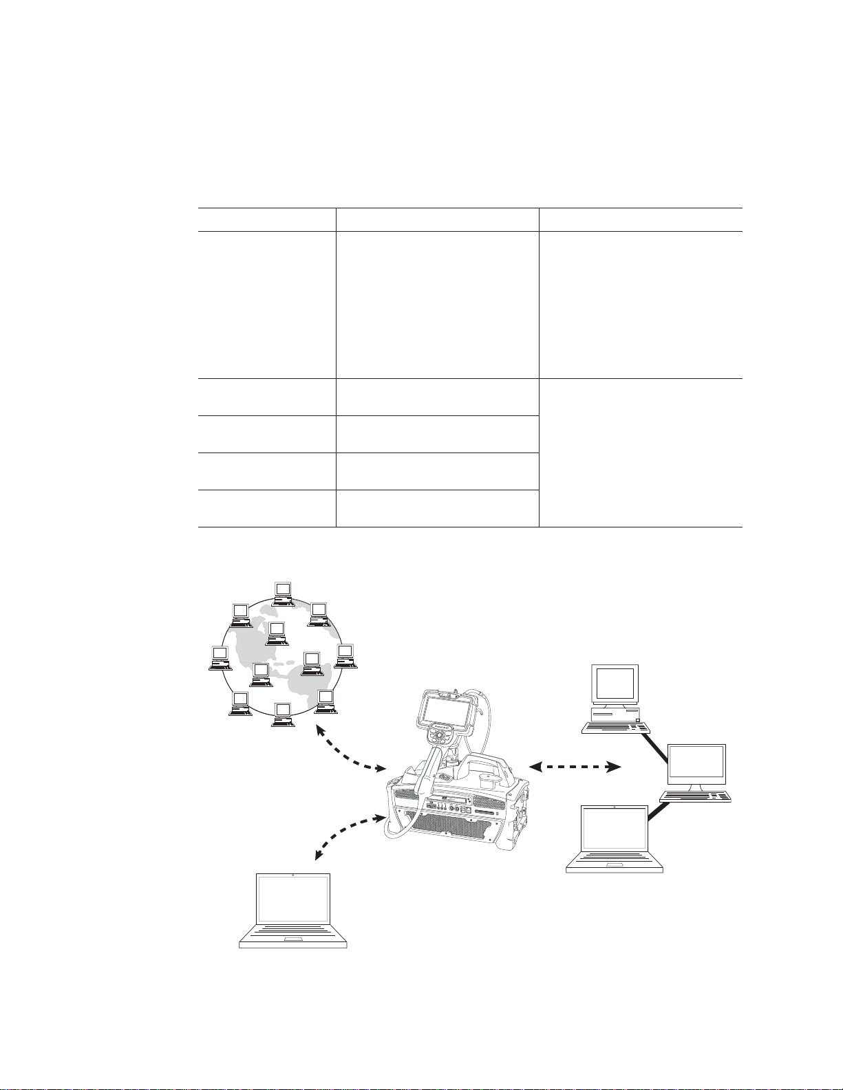
About the Network Package
The optional network software package — which delivers communication, file sharing, and
network functions for the XLG3 system — includes the following features.
Feature Description Details
PC and network
communications
You can communicate between the XLG3
system and a PC via a wired or wireless
network connection. Then you can browse
the XLG3 system from the PC and view,
download, or upload files. You can also
view live video from the PC (“video
streaming”). Note: The XLG3 system
cannot be connected directly to a PC. See
page 34.
“Communicating to a PC Through a Router
or Network” on page 34
“Reviewing Settings for Communications”
on page 45
“Sharing Files or Live Video With a PC” on
page 80
“To Save an Image” on page 66
Virtual desktop You can manage files and access other
applications via a graphical interface.
Internet browsing You can access web pages for viewing,
downloading, or uploading.
E-mail You can access any outside e-mail service
to send e-mail with files attached.
Internal WiFi A built-in wireless card lets you connect to a
wireless access point.
Internet
“Using the Desktop” on page 78
Network
Wired/Wireless
Router
PC
6 Chapter 1 Introduction GE Inspection Technologies XLG3 VideoProbe System
About the Menu Directed Inspection Package
Menu Directed Inspection (MDI) is the first software tool to standardize the inspection
process in the NDT industry. MDI software helps guide inspectors through the inspection
process and intelligently auto-generates a report—saving time, improving quality and
increasing productivity.
Menu Directed Inspection (MDI) software provides an advantage and convenience during
the inspection process. MDI makes labeling images and videos easier and automatically
generates reports from the VideoProbe within a few steps.
SYSTEM TOOLS
SYSTEM INFO
MDI LOAD
POWER MANAGEMENT UNLOAD
ANNOTATE
BACK SELECT
Benefits to using MDI include:
• Standardized Inspection Lists.
• Consistent Report Creation in MS Word format
• Data Management
• Decreased reporting time by up to 70%
• Increased speed and ease of sharing data
• Reduction of errors with guided inspections
SYSTEM TOOLS
SYSTEM INFO
MDI LOAD
POWER MANAGEMENT
UNLOAD
ANNOTATE
User Manual Chapter 1 Introduction 7
G
E
In
s
p
e
c
tio
n
T
e
ch
n
olo
g
ies
Everest XLG3
Controls, Indicators, Connectors, etc.
This section describes the controls, indicators, connectors, and other key elements for
each main system component:
• “Handset” on page 7
• “Control Buttons” on page 8
• “Probe” on page 9
• “Base Unit” on page 10
• “Case” on page 14
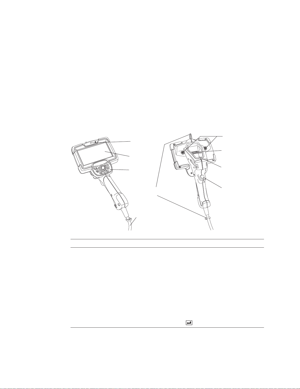
Handset
The handset is your interface to the XLG3 system.
A. Microphone
B. Display
C. Control
buttons
D. Shoulder-strap
loops
E. Handset cable
Item Description
A. Microphone Lets you record voice comments for video or still images.
B. Display Large, bright, high-resolution wide-VGA LCD screen.
C. Control buttons For details, see “Control Buttons” on page 8.
D. Shoulder-strap loops Strap is an optional accessory.
F. Flashlight LEDs
G. Electrical
connector
H. Fiberoptic
connector
I. Trigger
E. Handset cable Plugs into the base unit. Powers the handset, enables communication with the base unit,
and conducts light via a fiberoptic bundle from the lamp to the handset.
F. Flashlight LEDs Provide light for reading or writing. See “To Turn the Flashlight On and Off” on page 29.
G. Electrical connector Enables communication between base unit, handset, and probe.
H. Fiberoptic connector Couples light to the probe.
I. Trigger Same functions as the freeze/enter button (item B. on page 8).
8 Chapter 1 Introduction GE Inspection Technologies XLG3 VideoProbe System
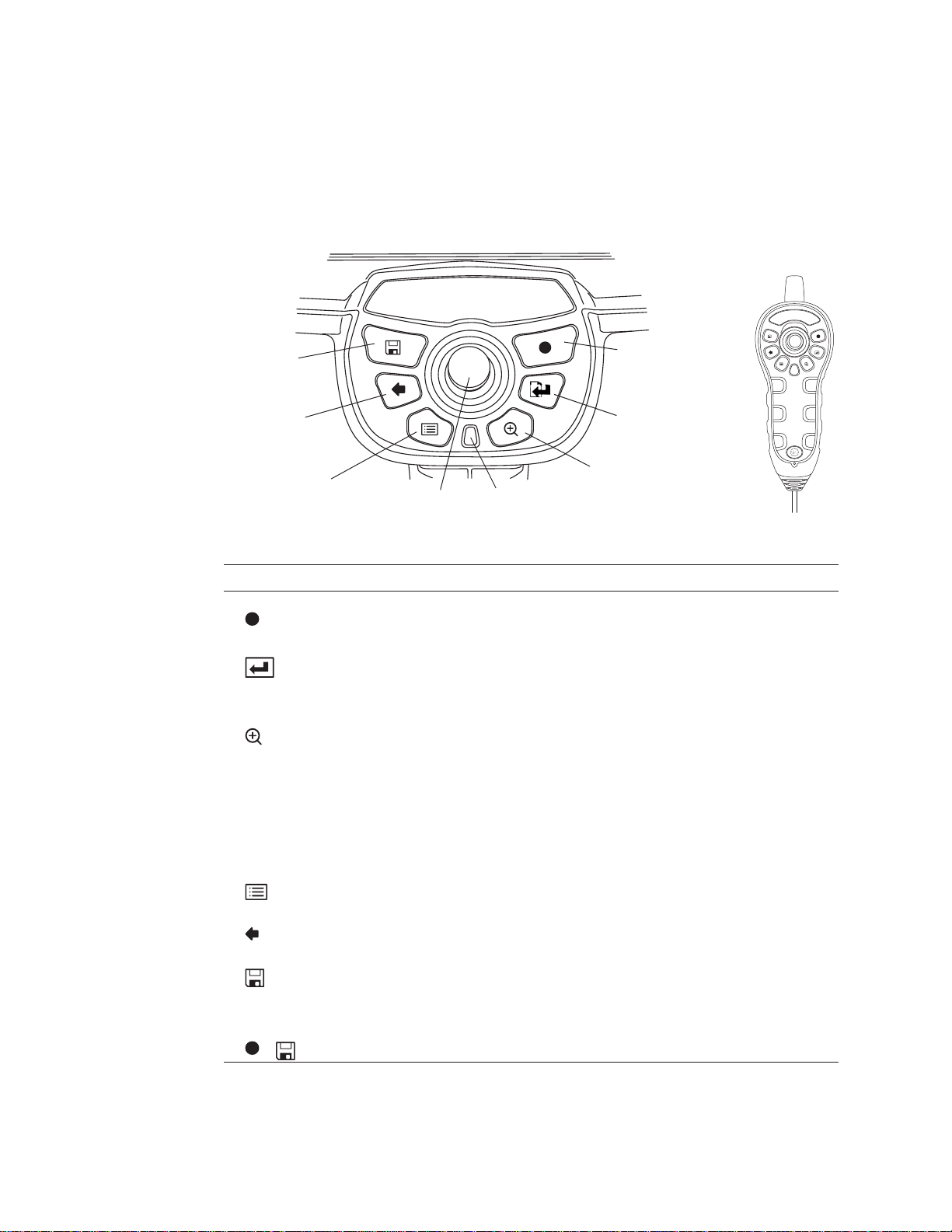
Everest XLG3
G. Exit/back
H. Save
A. Record
B. Freeze/enter
E. Joystick
F. Menu C. Zoom
D. Home &
Steer-and-Stay
Handset
Remote
Control
(Optional)
Control Buttons
The control buttons are conveniently located directly below the handset display. The same
controls are available on the optional remote control.
Everest XLG3
Item Description
A. Record Starts and pauses video recording. See “Working With Videos” on page 67.
B. Freeze/enter Performs same functions as the trigger (item I. on page 7).
C. Zoom Changes the zoom level. See “Zooming” on page 58.
D. Home &
Steer-and-Stay
E. Joystick Moves the probe tip, pans around zoomed images, moves through menus, and navigates
F. Menu Opens and exits menus. See “Navigating the Menus” on page 15.
G. Exit/back Exits a menu or operation.
H. Save Opens the save menu. See “Saving an Image” on page 65.
I. Restore factory
defaults
+ (5 seconds)
• Freezes and unfreezes images.
• Selects highlighted items.
• One-click report (see “Menu-Directed Mode”)
Performs two functions:
• Home (press and hold). See “To Straighten the Bending Neck (HOME)” on page 49.
• Steer-and-Stay (press quickly). See “To Hold the Bending Neck in Place
(Steer-and-Stay Mode)” on page 49.
the desktop.
Restores factory defaults for system settings. See “Restoring Factory Defaults” on page 16.
User Manual Chapter 1 Introduction 9
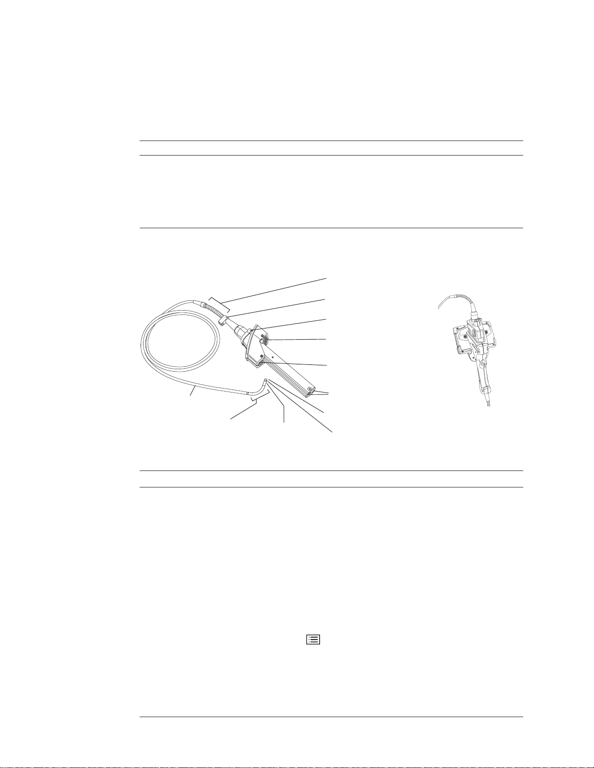
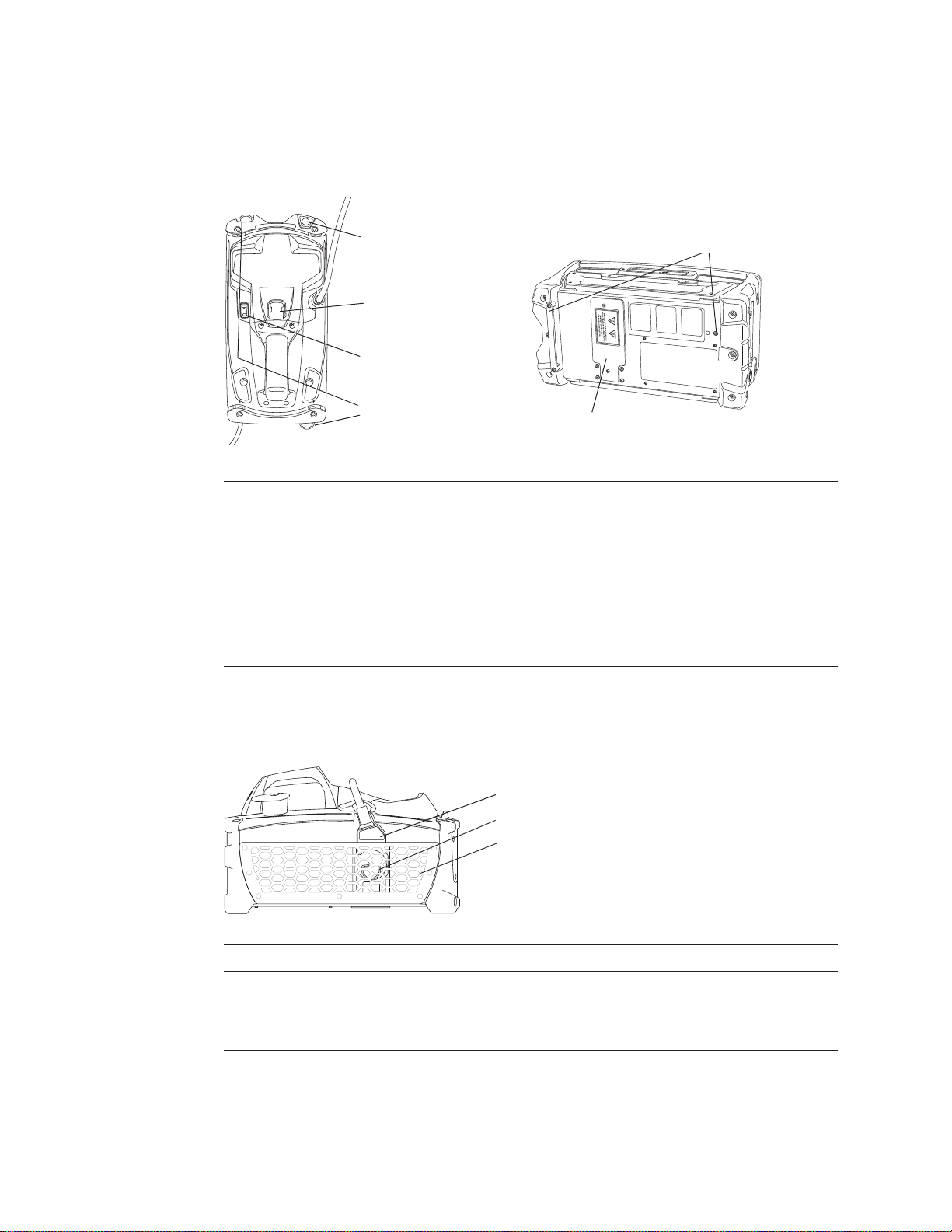
D. Electrical
connector
C. Latch
Probe inserted into handset
G. Optical tip
K. Insertion tube
J. Bending neck
F. Motor shaft
connectors
A. Strain relief
E. Fiberoptic
connector
I. Camera head
B. Clip
H. Temperature
sensor
Probe
The probe is the flexible eye of the system. Various probe models are available, with
insertion tubes of different diameters and different lengths.
Diameter (mm) Length (m)
3.9 2.0, 3.0
5.0 2.0, 3.0, 4.5
6.1 2.0, 3.0, 4.5, 6.0, 8.0, 9.6
6.2 Working Channel 3.2
8.4 2.0, 3.0, 4.5, 6.0, 8.0, 9.6
You can change probes quickly. You can also travel lighter by carrying one system and a
spare probe rather than a complete spare system.
Item Description
A. Strain relief Allows the insertion tube to twist up to 180 degrees in either direction.
B. Clip Holds probe end when not in use.
C. Latch C-shaped piece that locks the probe in the handset.
D. Electrical connector Enables communication between base unit, handset, and probe.
E. Fiberoptic connector Couples light from the handset into the insertion tube.
F. Motor shaft connectors For controlling the articulation cables.
G. Optical tip Removable part containing unique precision optics. For a list of available tips, see “Optical
H. Temperature sensor For 6.1 mm probes only. Displays a warning symbol and beeps when temperature at the
I. Camera head Made of titanium for superior protection. Contains a high-resolution, durable camera that
J. Bending neck The articulating section of the insertion tube.
K. Insertion tube A woven tube of tungsten wire that protects the electrical conductors and the light-
Tips” on page 147.
probe tip approaches or exceeds operating temperature limits. For an example of the
warning symbol, press , and select Setup > Temp Sensor.
provides clear, true-color images.
transmission fibers. Conducts light to the inspection area, and returns digital images.

10 Chapter 1 Introduction GE Inspection Technologies XLG3 VideoProbe System
J. DVD drive
(optional)
I. VGA video
output connector
M. Audio out
connector
N. External microphone
connector
A. Ethernet connector
C. USB connectors (3)
L. Power
switch
F. S-video input
connector
H. Air filter frame
Base Unit
The base unit is the XLG3 system’s communications center. It processes still images and
video, manages data, and connects to the external world with the optional network
package (via the front panel).
The base unit houses a processing board (CPU), system memory, power supply, 75-watt
high-intensity discharge (HID) arc lamp, and an integrated reel that can store even the
longest insertion tubes.
Base Unit, Front
K. Headset/external
speaker connector
B. CF card slot
D. Internal speakerG. Cooling fans E. S-video output
connector
Item Description
A. Ethernet connector For connecting to a network or to the Internet with the optional network package.
B. CF card slot For saving images and videos onto a compact Flash card.
C. USB connectors (3) For connecting various devices: a keyboard, a mouse, a memory stick, or other removable storage
D. Internal speaker For playback of comments that were saved with images or videos. The menu-driven volume control
E. S-video output connector For connecting a cable to the “video in” connector of a peripheral device, such as an external monitor or
F. S-video input connector For connecting a cable to the “video out” connector of a peripheral device, such as a camera.
G. Cooling fans For system ventilation.
H. Air filter frame For an optional air filter.
devices. All three connectors support USB 2.0 data rates and are compatible with USB 1.1
devices.You can connect or disconnect a keyboard or mouse any time.
affects this output.
recorder. S-video cables are available as accessories.
Allows the XLG3 system to capture, manipulate, annotate, and store images and videos from external
sources. When the system detects external input, it displays that input automatically.
S-video cables are available as accessories.

User Manual Chapter 1 Introduction 11
Item (cont.) Description (cont.)
I. VGA video output connector For connecting a PC-type monitor.
J. DVD drive (optional) For storing video files.
K. Headset/external speaker
connector
L. Power switch Turns the system on and off.
3.5 mm phone jack for a standard stereo headset or an external speaker. The menu-driven volume
control affects this output. If headset is plugged in, the internal speaker is automatically disabled.
M. Audio out connector 3.5 mm phone jack for a recording device (VCR, digital video tape recorder, etc.), or for powered
N. External microphone connector 3.5 mm phone jack for a headset microphone or standalone microphone. An external microphone has
speakers with their own volume control. Transmits line-level output signals (~2V RMS max). The menudriven volume control does not affect this output.
the same function as the built-in microphone. When an external microphone is plugged in, the system
automatically uses it for audio recording rather than the built-in microphone.
12 Chapter 1 Introduction GE Inspection Technologies XLG3 VideoProbe System
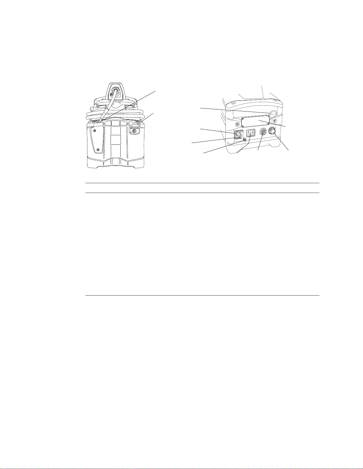
Left Side
C. AC power inlet
D. AC fuse
E. Ground lug F. AC output G. Battery (DC)
input
H. Battery (DC)
fuse
Right Side
B. Shoulder-strap
hooks
I. Internal
memory
card
A. Funnel
Base Unit, Sides
Item Description
A. Funnel Guides the insertion tube into the storage reel.
B. Shoulder-strap hooks Strap is included.
C. AC power inlet For connecting the power cord.
D. AC fuse Protects the circuitry when using AC power.
E. Ground lug Provides an earth ground if one is not available through the AC outlet.
F. AC output IEC-type F connector. The voltage and frequency of the power available at the AC output is
the same as the voltage and frequency applied to the inlet. Maximum output is 100 W.
G. Battery (DC) input For connecting a battery (optional).
H. Battery (DC) fuse Protects the circuitry when using a battery or other DC power source.
I. Internal memory card Card is in the drive behind the access panel. This card contains the operating system
software and the memory for storing images. This card is not user serviceable.
User Manual Chapter 1 Introduction 13
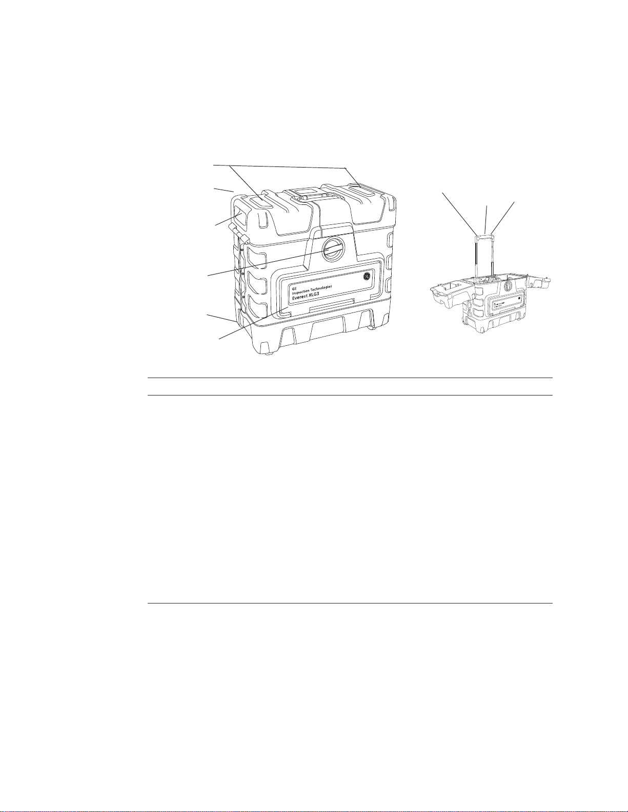
F. Lamp
Top Bottom
A. Funnel
D. Shoulder-strap
hooks
B. Socket for handset
holder
C. Power switch
E. Battery connection
points
Base Unit, Top and Bottom
Item Description
A. Funnel Guides the insertion tube into the storage reel.
B. Socket for handset holder Supports the handset holder.
C. Power switch Turns the system on and off.
D. Shoulder-strap hooks Strap is an optional accessory.
E. Battery connection points For holding the optional battery in place. The bracket is part of the battery assembly.
F. Lamp High-intensity discharge (HID) arc lamp, behind access panel.
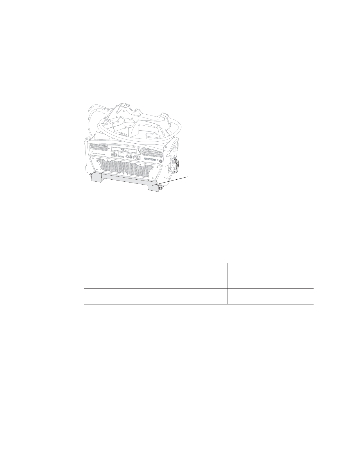
Base Unit, Back
Item Description
A. Handset power plug Connects the handset cable to the base unit.
B. Lock screw ring Latch that disconnects the power plug.
C. Pocket Mesh storage pocket.
A. Handset power plug
B. Lock screw ring
C. Pocket
14 Chapter 1 Introduction GE Inspection Technologies XLG3 VideoProbe System
D. Front latch
H. Release
button
G. Handle
A. Lids
C. Lifting handles
(top and both
sides)
F. Front door
E. Wheels
I. Socket for
handset
holder
B. Rear latch (not
visible here)
Small size shown
Case
Available in two sizes, the rugged XLG3 case protects the components and accessories
during storage, shipping, and operation. The system may be shipped in the storage case
without additional overboxing.
Item Description
A. Lids Allow access to components and accessories. Also provide ventilation to prevent
overheating when operating with base unit in the case.
B. Rear latch (not
visible here)
C. Lifting handles
(top and both sides)
D. Front latch Releases lids and front door.
E. Wheels Let you transport case easily.
F. Front door When operating with base unit in the case, the front door provides access to base unit’s
G. Handle Allows for easy transportation of system. Also supports handset holder.
H. Release button Releases handle to allow you to extend it. Also releases handset holder from handle.
I. Socket for handset
holder
Together with the front latch, this latch releases the lids.
Three handles let you lift case whichever way is most convenient.
front panel. Front door must be left open to provide ventilation and prevent overheating.
Supports handset holder.
User Manual Chapter 1 Introduction 15
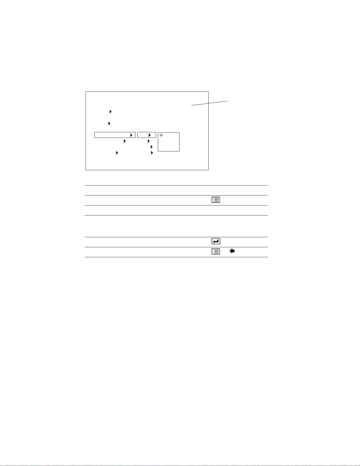
Navigating the Menus
You can navigate the menus using the control buttons on the handset or remote control.
For complete menu structure, see “Menu Trees” on page 141.
Live
Image
Menu Directed Inspection
Lamp
Probe Shut Down
Live Annotation
Video Record
Desktop
Flashlight
File Manager
Setup Menu
Desired Type of Navigation Control Button
To open a main menu
To highlight an item Joystick
To move between a parent menu and submenu
or
To change the highlighted option
To select the highlighted item
To exit menus or
Add
Edit
Clear
Show
Tex t
Preset
Arrow
Joystick
Example menu

16 Chapter 1 Introduction GE Inspection Technologies XLG3 VideoProbe System
Note
Restoring Factory Defaults
To restore factory defaults press and hold the Save and Record Buttons for five
seconds. Then confirm restoration of factory defaults. Performing this action restores the
following options.
• Battery Icon. ....... ............ ..... On
• Date/Time............................. ..... On
• Logo..................................... ..... On..
• Temperature Icon.................. ..... On
• Text Color.............................. ..... Green
• Image Format....................... ..... JPG
• Measurement Accuracy Index ... On
• Units of Measurement................. Inches
Upon next restart of VideoProbe, after restoring factory defaults, select the
desired language from the initial language selection screen.
User Manual Chapter 1 Introduction 17
Safety Information
Before using or servicing the system, you must read and understand the following safety
information.
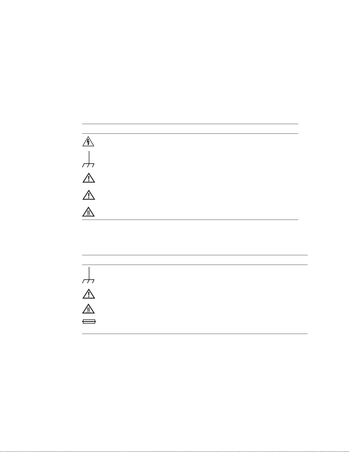
Symbols and Terms
When the following symbols and terms appear in this manual, they have the following
meanings:
Symbol Term Meaning
WARNING
WARNING
WARNING
Caution Caution statements indicate conditions or practices that could
Caution Surfaces may be hot.
When the following symbols appear on the product, they have the following meanings:
Symbol Meaning
Chassis grounding point.
See accompanying documentation.
DANGEROUS VOLTAGE.
ELECTRICAL SHOCK HAZARD — PROPER GROUNDING
REQUIRED.
Warning statements indicate conditions or practices that could
result in injury or loss of life.
result in damage to this product or other property.
Caution: Surfaces may be hot.
Fuse. For continued protection against fire, replace fuse only with specified
type and rating.

18 Chapter 1 Introduction GE Inspection Technologies XLG3 VideoProbe System
General Warnings
The following warning statements apply to use of the system in general. Warning
statements that apply specifically to particular procedures appear in the corresponding
sections of the manual.
WARNING ELECTRICAL SHOCK HAZARD — PROPER GROUNDING
REQUIRED. For procedures, see “Safe Powering and Grounding” on page 23.
WARNING DANGEROUS VOLTAGE. The outer panels of the base unit should
never be removed. Electrical shock hazard exists due to high internal voltage.
There are no user serviceable parts inside the base unit, except for the lamp and
fuses, which are accessible through the bottom and side panels, respectively.
Refer all service to listed service centers.
WARNING DANGEROUS VOLTAGE. Because the insertion tube is conductive,
and is connected to the base unit chassis and ground lug, do not allow the system
or its working tools to come in direct contact with any voltage or current source.
Prevent all contact with live electrical conductors or terminals. Damage to the
equipment and/or electrical shock to the operator may result.
WARNING LAMP EMITS ULTRAVIOLET, INFRARED, AND INTENSE VISIBLE
LIGHT. To prevent skin or eye injury, follow these instructions:
• Avoid looking at or touching the lamp and fiber bundle output while light is on.
• Do not operate the system when the handset is disconnected from the base
unit.
WARNING POSSIBLE EXPLOSION HAZARD. Do not use this system in
explosive environments.
WARNING USE PROPERLY. Using of any piece of this equipment in a manner
not specified by the manufacturer may impair the product’s ability to protect the
user from harm.
User Manual Chapter 1 Introduction 19
General Cautions
The following caution statements apply to use of the device in general. Caution statements
that apply specifically to particular procedures appear in the corresponding sections of the
manual.
Caution ALLOW ADEQUATE VENTILATION. Otherwise, the base unit might
overheat. Do not cover or drape anything over the base unit. To ensure adequate
airflow, provide a 3 inch (7.6 cm) distance between the base unit and any solid
objects. When the base unit is installed in the case (the preferred configuration),
the front door of the case must be open during operation to prevent overheating.
It is recommended that you also leave the lids open.
Caution REMOVE POWER PROPERLY. To remove all power from the
equipment, the disconnect device is the AC mains cord and, if equipped, the
battery connector.
Caution HANDLE PROBE CAREFULLY. Keep the insertion tube away from
sharp objects that might penetrate its outer sheath. Keep the whole insertion tube
as straight as possible during operation; loops or bends anywhere in the tube
decrease your ability to steer the probe tip. Avoid bending the insertion tube
sharply; the fragile fibers contained inside may break. Always use the Home
button to straighten the bending neck before withdrawing insertion tube from
inspection area or putting probe away. Never pull, twist, or straighten the bending
neck by hand; internal damage may result. At the first sign of damage, return the
probe for repair.
Caution CERTAIN SUBSTANCES MAY DAMAGE THE PROBE. For a list of
substances that are safe for the probe, see “Chemical Compatibility” on
page 137.
20 Chapter 1 Introduction GE Inspection Technologies XLG3 VideoProbe System
Informations sur la sécurité
Avant l'utilisation ou l'entretien du système, vous devez lire et comprendre les
informations de sécurité qui suivent.
Symboles et termes employés
Voici la signification des symboles et termes suivants employés dans ce manuel :
AVERTISSEMENT TENSION DANGEREUSE.
AVERTISSEMENT RISQUE DE CHOC ELECTRIQUE -
RACCORDEMENT À LA TERRE OBLIGATOIRE.
AVERTISSEMENT Les avertissements préviennent de situations ou de
pratiques risquant de provoquer des blessures, voire
un danger de mort.
Attention Les mentions Attention préviennent de situations ou
de pratiques risquant d'endommager le produit ou
d'autres biens.
Attention Les surfaces concernées peuvent être brûlantes.
Voici la signification des symboles et termes suivants apposés sur le produit :
Point de retour à la terre sur le châssis.
Voir la documentation jointe.
Attention: Les surfaces concernées peuvent être brûlantes.
Fusible. Pour maintenir la protection contre les risques d'incendie, remplacer le
fusible uniquement par un fusible du type et de l'ampérage spécifié.
User Manual Chapter 1 Introduction 21
Avertissements généraux
Les avertissements suivants s'appliquent à l'utilisation du système en général. Les
avertissements qui s'appliquent spécifiquement à des procédures particulières sont
indiqués dans les sections correspondantes de ce manuel.
AVERTISSEMENT RISQUE DE CHOC ELECTRIQUE - RACCORDEMENT À
LA TERRE OBLIGATOIRE. Pour les procédures, veuillez consulter la rubrique
“Safe Powering and Grounding” en page 23.
AVERTISSEMENT TENSION DANGEREUSE. Les panneaux extérieurs de la
base ne doivent jamais être enlevés. Le risque de choc électrique est dû à la
présence de tension électrique élevée dans l'unité. La base ne contient aucune
pièce dont l'utilisateur puisse effectuer l'entretien ; les seuls éléments concernés
sont la lampe et les fusibles qui sont respectivement accessibles par le panneau
inférieur et le panneau latéral. Pour les opérations d'entretien, veuillez vous
adresser aux centres de service indiqués.
AVERTISSEMENT TENSION DANGEREUSE. La gaine est conductrice et
reliée au châssis de la base et à la borne de retour à la terre ; ne laissez pas
l'appareil ni ses outils entrer en contact direct avec une source de tension ou
d'intensité électrique. Évitez tout contact avec des conducteurs ou des bornes
électriques sous tension. L'équipement risquerait d'être endommagé, ou
l'opérateur de subir un choc électrique.
AVERTISSEMENT LA LAMPE ÉMET DES ULTRAVIOLETS, DES
INFRAROUGES ET UNE LUMIÈRE VISIBLE INTENSE. Suivez les instructions
ci-dessous pour éviter une blessure cutanée ou oculaire :
• Évitez de regarder ou de toucher la lampe ou l'extrémité du faisceau de
fibres optiques lorsque la lampe est allumée.
• N'utilisez pas le système lorsque le manipulateur est déconnecté de la base.
AVERTISSEMENT RISQUE D'EXPLOSION. Ne pas utiliser ce système dans
un environnement à risque d'explosion.
AVERTISSEMENT UTILISER CORRECTEMENT. Si un élément de cet
équipement est utilisé d'une manière non indiquée par le fabricant, l'utilisateur
peut ne plus être protégé des risques de blessure.

22 Chapter 1 Introduction GE Inspection Technologies XLG3 VideoProbe System
Mentions générales Attention
Les mentions Attention qui suivent s'appliquent à l'utilisation de l'appareil en général. Les
mentions Attention qui s'appliquent spécifiquement à des procédures particulières sont
indiqués dans les sections correspondantes du manuel.
Attention PERMETTRE UNE VENTILATION ADÉQUATE. La base risque de
surchauffer si elle n'est pas bien ventilée. Ne la recouvrez pas avec un tissu ou
quoi que ce soit. Pour assurer un flux d'air adéquat, laissez un écart d'au moins
3 pouces (7,6 cm) entre la base et tout autre objet solide. Lorsque la base est
installée dans son boîtier (configuration recommandée), le panneau avant de
celui-ci doit être ouvert pour éviter la surchauffe de l'appareil pendant son
utilisation. Nous vous recommander de laisser aussi les couvercles ouverts.
Attention METTRE HORS TENSION CORRECTEMENT. Pour mettre
l'appareil totalement hors tension, débranchez le cordon d'alimentation CA et le
connecteur de batterie (le cas échéant).
Attention MANIPULER LA SONDE AVEC PRÉCAUTION. Maintenez la gaine
de la sonde à l'écart d'objets pointus ou tranchants qui risqueraient de traverser
son fourreau. Maintenez toute la gaine aussi droite que possible pendant
l'utilisation : en cas de boucle ou de courbure, il est plus difficile de piloter le bout
de la sonde. Évitez de trop courber la gaine car les fibres optiques qu'elle
contient sont fragiles et risquent de casser. Utilisez toujours le bouton de
rangement pour redresser le collet avant de rétracter la gaine de la zone
d'inspection ou de ranger la sonde. Ne manipulez jamais le collet à la main pour
le tirer, le courber ou le redresser : vous risqueriez de l'endommager à l'intérieur.
Envoyez la sonde en réparation au premier signe d'endommagement.
Attention CERTAINES SUBSTANCES RISQUENT D'ENDOMMAGER LA
SONDE. Pour consulter la liste des substances sans danger pour la sonde, voir
“Chemical Compatibility” en page 137.
 Loading...