

Page 1

INSTALLATION INSTRUCTIONS FOR YOUR NEW
STOP!
CAUTION:
30" ELECTRIC COOKTOP
Before you begin—Read these instructions completely and carefully.
IMPORTANT—Save these instructions for local inspector’s use.
IMPORTANT—OBSERVE ALL GOVERNING CODES AND ORDINANCES.
Note to Installer—Be sure to leave these instructions with the Consumer.
OWNER—Keep these instructions for future reference.
Note—This appliance must be properly grounded.
FOR YOUR SAFETY
For Personal Safety remove house
fuse or open circuit breaker before
beginning installation. Failure to do
so could result in serious injury or
even death.
• Be sure your cooktop is installed properly by a
qualified installer or service technician.
• To eliminate the risk of burns or fire by reaching over
heated surface elements, cabinet storage located
above the surface units should be avoided. If
cabinet storage space is to be provided, the risk can
be reduced by installing a range hood that projects
horizontally a minimum of 5" beyond the bottom of
the cabinets. Cabinet installation above the counter
unit may be no deeper than 13".
• The cooktop should be easy to reach and lighted
with natural light during the day.
• Always disconnect the electrical service to the unit
before repairing or servicing the counter unit. This
can be done by disconnecting the fuse or circuit
breaker. Failure to do this could result in a
dangerous or fatal shock. Know where your main
disconnect switch is located. If you don’t know,
have your electrician show you.
TOOL LIST
• 1/8" drill bit
• Electric or hand drill
• Flat bladed screwdriver
• Pencil
• Ruler or tape measure and straightedge
• Hand or saber saw
ELECTRICAL REQUIREMENTS
This appliance must be supplied with the proper voltage
and frequency, and connected to an individual, properly
grounded branch circuit, protected by a circuit breaker
or time delay fuse, as noted on rating plate.
Wiring must conform to National Electrical Codes. You
can get a copy of the National Electrical Code, ANSI/
NFPA No. 70-Latest Edition by writing:
National Fire Protection Association
Batterymarch Park
Quincy, MA 02269
We recommend that you have the electrical wiring and
hookup of your counter unit done by a qualified
electrician. After installation, have the electrician show
you where your main disconnect is located.
The range connector block is approved for copper wire
connection only, and if you have aluminum house
wiring, you must use special UL approved connectors
for joining copper to aluminum.
You must use a three-wire, A.C. 208Y/120Volt or 120/
240 Volt, 60 Hertz electrical system. A white (neutral)
wire is not needed for this unit.
Refer to the rating plate on your unit for the K.W. rating
for your counter unit.
SR10239
Pub. No. 31-10147
229C4053P018-4
1
Page 2

PREPARING THE OPENING
2 1/2" MIN.
clearance from
cutout to side
wall on the left
of the unit
30" MIN.
clearance from
countertop to
overhead surface
1 1/2" MIN.
clearance from
cutout to side
wall on the right
of the unit
13" MAX. Depth
of unprotected
overhead cabinets
18" MIN.
height from
countertop to
nearest cabinet on
either side of unit
19 3/8"
28 1/2"
20 1/2"
29 1/2"
28 1/2"
*
3 3/8"
1 3/4"
2 1/2" MIN.
19 5/8"
COOKTOP
INSTALLATION
STOP!
The following MINIMUM clearance dimensions must be
maintained:
• To insure accuracy, it is best to make a template
when cutting the opening in the counter. See Figure
2 for all necessary dimensions.
• Thirty inches (30") minimum vertical clearance from the
cooktop to the nearest unprotected overhead surface.
• One and one half inches (1 1/2") minimum on the right
and two and one half inches (2 1/2") minimum clearance
on the left from counter unit to side wall to a height of
eighteen inches (18").
• Make sure the wall coverings, countertop and cabinets
around the range can withstand heat (up to 200°F)
generated by the range, oven or cooktop.
Fig. 2
*NOTE: Depth of the unit at the conduit location
(right rear) is 4 3/4".
• (1 3/4") between counter unit rear edge and wall
behind unit.
• (2 1/2") between front edge of counter unit and the
front edge of the counter.
• Five inches (5") minimum vertical clearance between
the cooktop bottom and any combustible surface.
Fig. 1
IMPORTANT:
Remove all packing
material and literature from the
cooktop before connecting any
electrical supplies.
Before installing the counter unit or moving it to another
location, have the electrician verify:
• That your home is provided with adequate electrical
service.
• That the addition of the counter unit will not overload
the household circuit on which it is used.
Install an approved junction box where it will be easily
reached through the front of the cabinet where the
counter unit will be located. The counter unit has 3 feet
of conduit.
2
Page 3
BE SURE THIS CUT DOES NOT
INTERFERE WITH CABINET
STRUCTURE AT FRONT
16" MIN.
(40.6 CM)
BE SURE THIS CUT DOES NOT INTERFERE
WITH CABINET STRUCTURE AT FRONT
IMPORTANT: The junction box must be located
where it will allow considerable slack in the
conduit for serviceability. See Figure 3.
16" MIN.
SUGGESTED MOUNTING OF AN APPROVED
JUNCTION BOX
(NOT FURNISHED WITH UNIT)
Install the counter unit in the cutout opening.
NOTE: If the unit is being installed in a blind
counter (one with no cabinet opening below),
wire connections must be made before
putting the unit into the cutout.
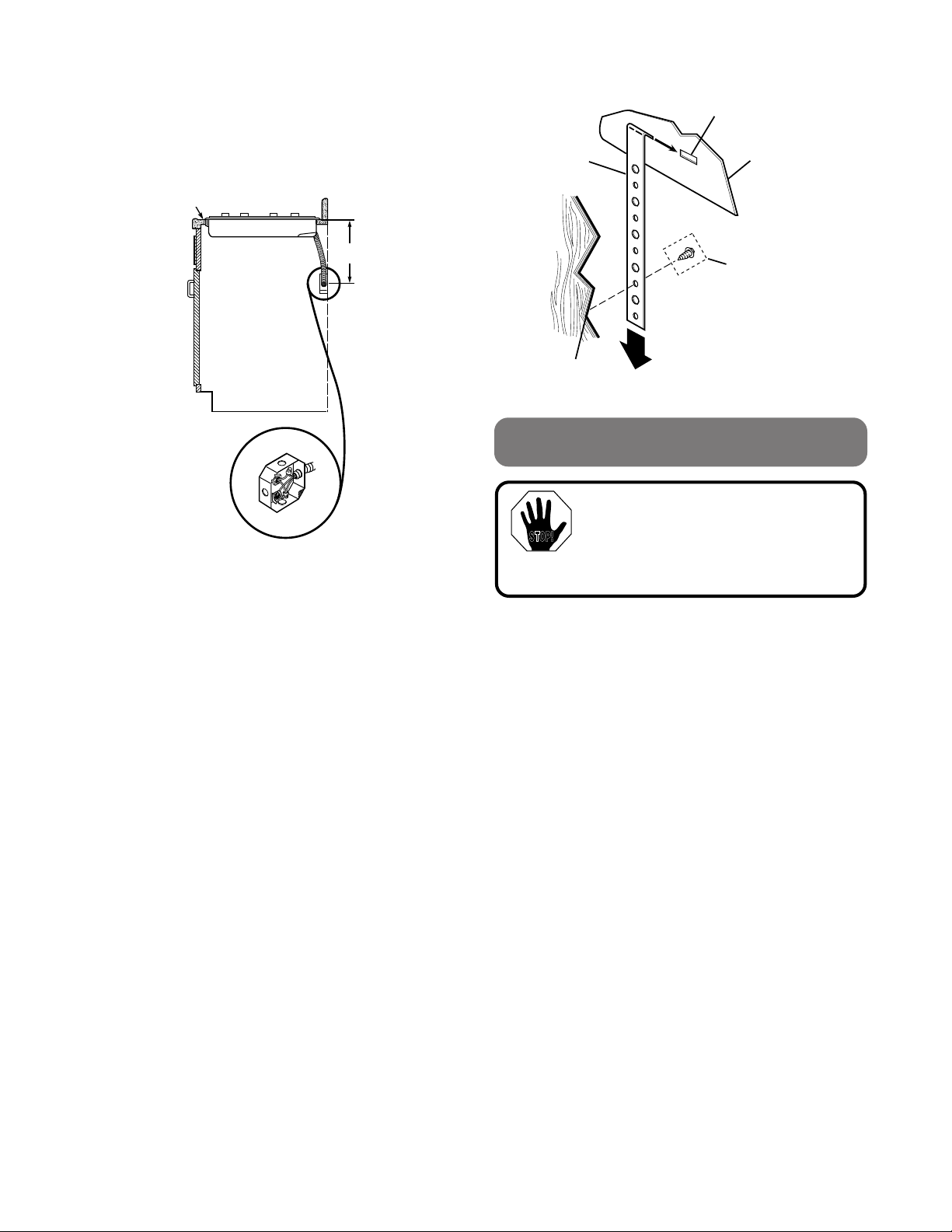
INSTALLING IN A STANDARD OR TILE
COUNTER:
To attach the unit to a standard counter, insert the hold
down bracket in the slots on each side of the unit. Use
the screws provided to attach the unit to the counter as
shown.
HOLD DOWN
BRACKET
MOUNTING
SLOT
BURNER BOX
SIDES
USE SUITABLE
FASTENERS FOR
ANCHORING IN
CABINET SIDES
CABINET
SIDES
ELECTRICAL CONNECTIONS
STOP!
Fig. 3
Fig. 4
The electrical power to the counter
unit supply line must be shut off
while line connections are being
made. Failure to do so could result
in serious injury or death.
When making the wire connections, use the entire
length of conduit provided (3 feet). The conduit must not
be cut.
Connect the red and black leads from the counter unit
conduit to the corresponding leads in the junction box.
The bare ground wire in the conduit is connected to the
counter unit frame. When connecting to a 3-conductor
branch circuit, if local codes permit, connect the bare
ground connector lead of the range to the branch circuit
neutral (gray or white in color).
SPECIAL GROUNDING INSTRUCTIONS
• When connecting to a 4-conductor branch circuit;
• When local codes do not permit grounding through
neutral;
• When installing counter unit in a mobile home:
Attach the appliance grounding lead (green or bare
copper) to the residence grounding conductor (green
or bare copper) in accordance with local codes.
3
Page 4

BE SURE THIS CUT DOES NOT
INTERFERE WITH CABINET
STRUCTURE AT FRONT
16" MIN.
(40.6 CM)
— Printed in LaFayette, Georgia —
Recycled Paper
NOTE TO ELECTRICIAN:
16" MIN.
Fig. 5
BE SURE THIS CUT DOES NOT INTERFERE
WITH CABINET STRUCTURE AT FRONT
4
SR10239
Pub. No. 31-10147
229C4053P018-4
The power leads supplied with this appliance
are U.L. recognized for connection to larger
gauge household wiring. The insulation of
these leads is rated at temperatures much
higher than the temperature rating of
household wiring. The current carrying
capacity of a conductor is governed by the
wire gauge and also the temperature rating
of the insulation around the wire.
NOTE: ALUMINUM WIRING
A. WARNING:
IMPROPER CONNECTION OF ALUMINUM
HOUSE WIRING TO THE COPPER LEADS
CAN RESULT IN A SERIOUS PROBLEM.
B. Splice copper wires to aluminum wiring
using special connectors designed and
U.L. approved for joining copper to
aluminum and follow the manufacturer’s
recommended connector procedure
closely.
NOTE: Wire used, location and enclosure of
splices, etc., must conform to good wiring
practice and local codes.
SUGGESTED MOUNTING OF AN APPROVED
JUNCTION BOX
(NOT FURNISHED WITH UNIT)
Page 5

INSTRUCCIONES DE INSTALACION PARA SU NUEVA
STOP!
CUBIERTA DE COCINAR ELECTRICA DE 30"
Antes de empezar—Lea estas instrucciones completa y cuidadosamente.
IMPORTANTE—Guarde estas instrucciones para el uso del inspector local.
IMPORTANTE—OBSERVE TODOS LOS CODIGOS Y ORDENANZAS VIGENTES.
Nota al Instalador—Cerciórese de dejar estas instrucciones con el consumidor.
DUEÑO—Guarde estas instrucciones para referencia futura.
Nota—Este aparato electrodoméstico tiene que hacer tierra adecuadamente.
PARA SU SEGURIDAD LISTA DE HERRAMIENTAS
PRECAUCION:
Para seguridad personal, saque el
fusible de la casa o abra el circuito
desconectador antes de empezar la
instalación.
• Asegúrese de que su cubierta de cocinar esté
correctamente instalada por un instalador
competente o un técnico de servicio.
• Para eliminar el riesgo de quemaduras o fuego
tratando de tomar algo por sobre los elementos de
superficie calientes, debería evitar tener gabinetes
de almacenamiento arriba de las unidades de la
superficie. Si tiene gabinetes de almacenamiento,
el riesgo se puede reducir instalando una campana
de estufa que se proyecte horizontalmente un
mínimo de 5" más allá de la base de los gabinetes.
La instalación de los gabinetes sobre la unidad del
mesón no debería tener más de 13" de profundidad.
• La cubierta de cocinar debe ser de acceso fácil y
alumbrada con luz natural durante el día.
• Siempre desconecte la fuente de electricidad de la
unidad antes de una reparación o de un servicio de
la cubierta de cocinar. Esto se puede hacer
desconectando el fusible o el interruptor del circuíto
Si esto no se hace, podría resultar en un golpe
eléctrico peligroso o fatal. Sepa donde está el
interruptor principal. Si no lo sabe, haga que el
electricista se lo muestre.
SR10239
Pub. No. 31-10147
229C4053P018-4
• Taladro de punta de 1/8"
• Taladro eléctrico o manual
• Atornillador de cabeza plana
• Lápiz
• Regla
• Sierra de mano o eléctrica
REQUERIMIENTOS ELECTRICOS
Este aparato debe ser alimentado con el voltage y la
frecuencia adecuada, y conectado a una rama del
circuíto que sea individual y que haga tierra
adecuadamente, que esté protegida por un interruptor
de circuíto o un fusible de tiempo demorado, como se
instruye en la tabla de valores.
El alambrado debe estar de acuerdo con los Códigos
Eléctricos Nacionales (National Electric Codes). Usted
puede conseguir una copia de National Electric Codes,
ANSI/NFPA No 70 Latest Edition (Ultima Edición)
escribiendo a:
National Fire Protection Association
Batterymarch Park
Quincy, MA 02269
Recomendamos que el alambrado y las conexiones
eléctricas de su unidad de mesón sean hechas por un
electricista competente. Después de la instalación,
pídale al electricista que le muestre donde está el
interruptor desconectador principal.
El bloque de conexiones de la estufa está aprobado
para conexiones de cobre solamente, y si el alambrado
de su casa es de aluminio, usted tiene que usar
conectores UL aprobados especiales para juntar el
cobre al aluminio.
Usted debe usar un sistema eléctrico de tres alambres,
C.A. 208Y/120 Voltios 120/240 Voltios, 60 Hertz. Un
alambre blanco (neutral) no es necesario para esta
unidad. Si no se usa, el alambre blanco que viene de
la fuente eléctrica de la casa se puede cubrir con una
cinta y terminar en la caja de conexiones.
Consulte la tabla de valores en su unidad para el valor
K.W. de su unidad.
1
Page 6

PREPARE LA ABERTURA
2 1/2" MIN.
de espacio
desde el hoyo
a la pared del
lado izquierdo
de la unidad
30" MIN.
de espacio desde
la superficie del
mesón hasta la
superficie de
arriba.
1 1/2" MIN.
de espacio desde
el hoyo a la pared
del lado derecho
de la unidad
13" MAX. profundidad
de los gabinetes sin
protección de arriba
18" MIN.
de altura desde
la superficie del
mesón al gabinete
a cualquier lado
de la unidad
Fig. 2
*NOTA: La profundidad de la unidad en el
lugar del conductor (derecha
trasera) es de 4 3/4'.
INSTALACION
19 3/8"
28 1/2"
20 1/2"
29 1/2"
28 1/2"
*
3 3/8"
1 3/4"
2 1/2" MIN.
19 5/8"
CUBIERTA DE
COCINAR
STOP!
Se deben mantener las siguientes dimensiones
MINIMAS de espacio:
• Para asegurar la exactitud, es mejor hacer un patrón
cuando haga el corte en el mesón. Vea la figura 2
para todas las dimensiones necesarias.
• Treinta pulgadas (30") mínimo de espacio vertical
desde la cubierta de cocinar hasta la superficie de
arriba sin protección más cercana.
• Una y media pulgada (1 1/2") mínimo de espacio a
la derecha y dos y media pulgadas (2 1/2") mínimo
de espacio a la izquierda desde la unidad de mesón
a las murallas de los lados y una altura de dieciocho
pulgadas (18").
• CercIórese de que los revestimientos de la muralla,
mesón y gabinetes pueden soportar el calor
generado por la estufa, horno y cubierta, hasta
200°F.
• (1 3/4") min. entre la orilla delantera de la unidad y
la orilla del frente del mesón.
• (2 1/2") min. mínimo de espacio vertical debajo del
fondo de la cubierta de cocinar.
• Cinco pulgadas (5") mínimo de espacio vertical
entre el fondo de la cubierta y cualquier superficie
combustible.
Fig. 1
IMPORTANTE:
Saque todos los materiales de
empaque y la literatura de la
cubierta para cocinar antes de
conectar el gas y la electricidad a
la estufa.
Antes de instalar la unidad o cambiarla a otra ubicación,
haga que el electricista verifique:
• Que su casa tenga un servicio eléctrico adecuado.
• Que la adición de la unidad de mesón no recargará
el circuíto de la casa que se esté usando.
Instale una caja de conexiones aprobada donde sea
accesible fácilmente a través del frente del gabinete
donde la unidad estará ubicada. La unidad de mesón
tiene 3 pies de conductores.
2
Page 7

IMPORTANTE: La caja de conexiones debe
ABARAZERA
RANURA DE MONTAJE
LADO DE CAJA
DE QUEMADOR
USE TORNILLOS
ADECUADOS PARA
PEGAR A LOS LADOS
DEL GABINETE.
AL LADO
DE GABINETE
CONEXIONES ELECTRICAS
BE SURE THIS CUT DOES NOT
INTERFERE WITH CABINET
STRUCTURE AT FRONT
16" MIN.
(40.6 CM)
16" MIN.
CERCIORESE DE QUE ESTE
CORTE NO INTERFIERA CON LA
ESTRUCTURA DEL GABINETE AL
FRENTE
Fig. 3
Fig. 4
Instale la unidad de mesón en la abertura.
NOTA: Si la unidad está siendo instalada en
un gabinete ciego (uno sin puerta abajo), las
conexiones de los alambres se deben hacer
antes de poner la unidad en la abertura.
INSTALACION DE LA UNIDAD EN UN MESON
NORMAL O DE BALDOSA:
Para pegar la unidad a un mesón normal, meta las
abrazaderas a cada lado de la unidad. Use los
tornillos que se proveen para pegar la unidad al
mesón como se muestra.
STOP!
estar ubicada de manera que provea una
soltura considerable en los circuítos para el
servicio. Vea la figura 3.
SUGERENCIA DE MONTAJE DE UNA CAJA DE
(NO SE PROVEE CON LA UNIDAD)
CONEXIONES APROBADA
El poder eléctrico a los cables de la
unidad de mesón debe apagarse
mientras se hacen las conexiones.
Si esto no se hace podría resultar en
heridas serias o muerte.
Cuando se hagan las conexiones de los alambres, use
el largo completo del conductor que se provee (3
pies). El conductor no debe ser cortado.
Conecte las puntas roja y negra del conductor de la
unidad de mesón a las puntas correspondientes en la
caja de conexiones.
El alambre pelado para hacer tierra en el conductor se
conecta al cuerpo de la unidad de mesón. Cuando se
conecta a un circuíto conductor de tres ramas, si los
códigos locales lo permiten, conecte la punta del
conector pelado para hacer tierra a la rama neutral del
circuíto (color gris o blanco).
INSTRUCCIONES ESPECIALES PARA
HACER TIERRA
• Cuando conecte a un circuíto conductor de 4
ramas;
• Cuando los códigos locales no permiten hacer
tierra a través de neutral;
• Cuando se instala una unidad de mesón en una
casa móvil:
Conecte el alambre para hacer tierra de la estufa
(verde o cobre pelado) al conductor para hacer tierra
de la residencia (verde o cobre pelado) de acuerdo a
los códigos locales.
3
Page 8

NOTA AL ELECTRICISTA:
BE SURE THIS CUT DOES NOT
INTERFERE WITH CABINET
STRUCTURE AT FRONT
16" MIN.
(40.6 CM)
16" MIN.
Fig. 5
CERCIORESE DE QUE ESTE
CORTE NO INTERFIERA CON LA
ESTRUCTURA DEL GABINETE AL
FRENTE
4
— Impreso en LaFayette, Georgia —
Los conectores eléctricos que se proveen
con esta estufa son reconocidos por U.L.
para conexiones con alambres de casa de
tamaño más grande. El aislante de estos
conectores tienen un valor de temperatura
más alto que el valor de temperatura de los
alambres de las casas. La capacidad de
conducción de corriente de un conductor es
gobernado por el tamaño del alambre y
también por el valor de temperatura del
aislante alrededor del alambre.
NOTA: ALAMBRES DE ALUMINIO
A. ADVERTENCIA:
LAS CONEXIONES INADECUADAS DE
LOS ALAMBRES DE ALUMINIO DE
LACASA A LOS CONECTORES DE
COBRE PUEDEN RESULTAR EN
SERIOS PROBLEMAS.
B. Conecte alambres de cobre a alambres
de aluminio usando conectores
especiales diseñados y aprobados por
U.L. para juntar cobre y aluminio y
siga los procedimientos para hacer
conexiones recomendados por el
fabricante cuidadosamente.
NOTA: El alambre que se use, ubicación y
cerraduras de las junturas, etc., deben estar
en conformidad con las buenas prácticas de
alambrado y los códigos locales.
SUGERENCIA DE MONTAJE DE UNA CAJA DE
CONEXIONES APROBADA
(NO SE PROVEE CON LA UNIDAD)
SR10239
Pub. No. 31-10147
229C4053P018-4
Papel Reciclado
 Loading...