

Page 1
GE
Installation Guide
Lighting
Lumination™ Linear Suspended LED Luminaire
(EL Series – Cable Suspension Surface Mount Driver)
BEFORE YOU BEGIN
Read these instructions completely and carefully.
RISK OF ELECTRIC SHOCK
• Turn power off before inspection, installation or removal.
• Properly ground electrical enclosure.
RISK OF FIRE
• Follow all NEC and local codes.
• Use only UL approved wire for input/output connections.
Minimum size 18 AWG (0.82 mm2).
Save These Instructions
Use only in the manner intended by the manufacturer.
If you have any questions, contact the manufacturer.
Important
Wear work gloves to prevent dirt and oil from being
transferred to the luminaire.
CAUTION
RISK OF DAMAGE:
• Luminaire may fall down if not installed properly
• Remove protective lm on Light Guide only after installation
• Do not touch Light Guide to avoid dirt, oil and ngerprints
WARNING/AVERTISSEMENT
RISQUES DE DÉCHARGES ÉLECTRIQUES
• Coupez l’alimentation avant d’’inspecter, installer ou déplacer le luminaire.
• Assurez-vous de correctement mettre à la terre le boîtier d’alimentation électrique.
RISQUES D’INCENDIE
• Respectez tous les codes NEC et codes locaux.
• N’utilisez que des ls approuvés par UL pour les entrées/sorties de
connexion. Taille minimum 18 AWG (0.82 mm2).
Tools and Components Required
• #2 Philips head screwdriver
• UL Recognized wire connectors
• UL Recognized outlet box 2”x4”
• Ceiling fasteners (3 sets)
Prepare Electrical Wiring
Electrical Requirements
• The LED driver must be supplied with 120-277 VAC,
50/60 Hz (in 120-277V application).
• For Series EL0XD, the unit must be supplied with
347 VAC, 60 Hz (in 347V application).
• Connected to an individual properly grounded
branch circuit, protected by a 15 or 20 ampere
circuit breaker. Use min. 75°C supply conductor.
Grounding Instructions
• The grounding and bonding of the overall system
shall be done in accordance with National Electric
Code (NEC) Article 600 and local codes.
imagination at work
Page 2
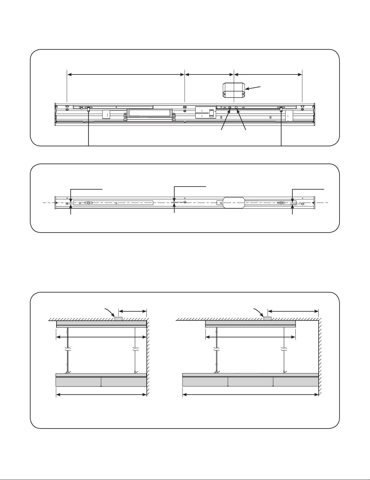
Screw Holes Position On Ceiling For Mounting Driver Box
Side view
Top view
550 mm (21.7 in.)
Dimming control wire hole Main supply hole
5 mm (0.2 in.) 5 mm (0.2 in.)
225 mm (8.9 in.) 325 mm (12.8 in.)
Outlet box
3 mm (0.1 in.)
Luminaire Installation Position
382 mm
Outlet box Outlet box
Ceiling Ceiling
1215 mm (47.8 in.) 1215 mm (47.8 in.)
1219 mm (48.0 in.) 1829 mm (72.0 in.)
4 ft. Luminaire: When the outlet box mounted to
ceiling, the distance between the center of the outlet
box to wall should be no less than 15 in.
(15.0 in.)
687 mm (27.0 in.)
Wall Wall
6 ft. Luminaire: When the outlet box mounted to
ceiling, the distance between the center of the outlet
box to wall should be no less than 27 in.
Page 3

Luminaire Installation
Disconnect clips with screwdriver
Front cover
Take out driver box from packaging. Pull open front cover
1
by disconnecting the clips on two end caps.
Ceiling
2”x4” outlet box
Outlet box in ceiling
Dimming line
(optional)
Connect wires from driver box to the wire leads in outlet
2
box using wire nuts (white to white, black to black, green
to green). Connect the dimming wires if needed.
Optional dimmer: When connecting dimming controller,
wires must be run through a separate knockout hole
equipped with bushing provided.
Risk of damage: Make sure that supply connection,
light xture wiring, and dimming cables are connected
to proper driver inputs. Wrong connection may cause
damage to the product.
AC line
Fastener Fastener Fastener
Surface mount driver box
Align the driver box with the 2”x4” outlet box. Then
3 4
mount the driver box to ceiling with 3 fasteners capable
of supporting >30 lbs. each. The outlet box should be
aligned with the driver box allowing no exposed gaps to
outlet box. WARNING: Use fasteners (not supplied) that
are appropriate for use with your mounting surface
and weight of the xture.
Adjustable nut
Hold the Light Engine and move to suspension cable.
5
Connect two adjustable nuts to studs on top of the
luminaire.
Wear work gloves to prevent dirt and oil
from being transferred to the luminaire.
Unpack Light Engine from packaging. Properly inspect
for defects before installing. Make sure the Light Engine
is only carried out by holding two ends of it. Do not
touch Light Guide when taking out.
Wire clamp
Flexible cord
Before connecting exible cord to the output wires of the
6
driver, form a knot in the end of the cord to act as a strain
relief. Be sure the knot is inside the enclosure. Install wire
clamp to top surface of the driver box and then connect
the red (line) and black (neutral) wires from light engine to
red (line) and blue (neutral) wires from the power supply.
Green wire to G position on driver box.
Page 4

Front cover
Driver box
Connect the ground wire from front cover to the ground
7
screw on the top plate. (Other wires hidden for clarity).
Plastic clip
Flexible cord
Put back the front cover. Push to get it snapped by two
8
end caps. Attached suspension cable and cords with
Suspension cable
plastic clips provided.
0-10 Volt Dimming
A
BLU/WHT
BLK/WHT
YEL
GRY
LED Driver
VIO
VIO/WHT
0-10V -
0-10V +
To 0-10V
Dimmer
DALI Controller
B
BLU/WHT
BLK/WHT
LED Driver
VIO/WHT
YEL
GRY
VIO
DALI/Prog
DALI/Prog
To DALI
Controller
Optional Installation (For 120-277V and 347V Application): 0-10 Volt Dimming or DALI Lighting Controller. Follow gure A for 0-10V
and gure B for DALI. Run wires from controller through a different knockout than the AC input wire. At output side of LED Driver, make
appropriate connections using twist-on wire connectors. Follow lighting controller installation instructions.
Luminaire Inter Connection and Alignment
Inter connector
Light Guide clip
Put inter connector on the top of two luminaires and make
1
sure that the slot of the inter connector cross the two end
caps.
This device complies with Part 15 of the FCC Rules. Operation is subject to the following two conditions: (1) This device may not cause harmful interference, and (2) this device must
accept any interference received, including interference that may cause undesired operation. This Class [A] RFLD complies with the Canadian standard ICES-003. Ce DEFR de la classe
[ A ] est conforme à la NMB-003 du Canada.
Note: This equipment has been tested and found to comply with the limits for a Class A digital device, pursuant to part 15 of the FCC Rules. These limits are designed to provide
reasonable protection against harmful interference when the equipment is operated in a commercial environment. This equipment generates, uses, and can radiate radio frequency
energy and, if not installed and used in accordance with the instruction manual, may cause harmful interference to radio communications. Operation of this equipment in a residential
area is likely to cause harmful interference in which case the user will be required to correct the interference at his own expense.
Push the inter connector into the luminaires. Remove the
2
protective lm and insert the Light Guide clip between
the two Light Guides.
GE Lighting • 1-888-MY-GE-LED (1-888-69-43-533) • www.gelighting.com
GE Lighting Solutions, LLC is a subsidiary of the General Electric Company. The GE brand, logo, Lumination are trademarks of the General Electric Company. USG and Logix are trademarks of USG Interiors, LLC.
© 2013 GE Lighting Solutions, LLC. Information provided is subject to change without notice. All values are design or typical values when measured under laboratory conditions.
IND081-101113
 Loading...