

GE DSXH47GG1WW, DSXH47EG1WW Owner’s Manual
{J
ge.com
Safety Instructions ............ 2-5
Operating Instructions
Care and Cleaning .................... 8
Controls ............................. 6
Features ............................. 7
Loading and Using the Druer .......... 8
Installation Instructions ..... 9-18
Electrical Installation for
Electric Druer ................... 16, 17
Electrical Requirements .............. 11
Exhausting the Druer ............. 12, 13
Gas Connection for Gas Druer ........ 18
Gas Supplu Requirements ............ 13
Location of Your Druer ............... 14
Mobile Home Installation ............. 15
Preparing to Install Your Druer ..... 9, 10
Reversing the Door Swing ............ 18
DSXH4 7
Troubleshooting Tips ........ 19-21
Consumer Support
Consumer Support .................. 24
Warrantu .......................... 23
134867300175D1807P58149-90313-i01-07JR
IMPORTANTSAFETYINFORMATION.
READALLINSTRUCTIONSBEFOREUSING.
A WARNING!
For your safety, the information in this manual must be followed to minimize the risk of fire
or explosion, electric shock, or to prevent property damage, personal injury, or death.
• Do not store or use gasoline or other
flammable vapors and liquids hi the
vicinity of this or any other appliance.
• Installation and service must be performed
by a qualified installer, service agency or
the gas supplier.
WHATTODOIF YOUSMELLGAS:
]Do not try to light a match, or cigarette, or
turn oll any gas or electrical appliance.
[]Do not touch any electrical switch; do not
use any phone in your building.
[]Clear the room, building or area of all
occupants.
California Safe Drinking Water and ToxicEnforcement Act
This act r_quir(s Ihc governor of California to publish a list ofsul_tanc_s kno_n to th_ state to cause canc_ r,
birth def_ cts or ()they re[)l-Odll(liX,{ hal-Ill _tlld le(ltlil-e_, })ll';ille_,s_ _, to _V_?ll-ll C[iSlol)l_ l-s o_" DOt_ llt]_ll _ xl)oSt/l(:
10 SLIC}I SLI[)S[}?IIIC(?S.
G_/S _l[)])]i_/ll({!S ({/11 ({IllS(! lllillOf ( X[)I)SIlI'(1{) fO!/l" O_" [}I(!S(_ SIIbS[_III(CS, ll_lllle|y I){ llZ1211( C{/I'[)OII lllOlloxid_ _
formald_ hyd,_ and soot, cruised primalily by the incomplete combustion _,_tl'latU ml gas or I J) tilds.
Properly a(!jusled dlTers _dll minimize in< ompl_ le combustion, l_;xposure to th_:_s_substanc_:_s _an be
minimized filrth_:_r by l>rop_:_rlyventing the dl)'e r Io the ouvtool_,.
[]Immediately call your gas supplier from
a neighbors phone. Follow the gas
suppfier's instructions carefully,
[] ff you cannot reach your gas suppfier, call
the fire departmenL
2
PROPERINSTALLAtiON
This dryer must be properly installed and located in accordance with the Installation Instructions
before it is used,
• Prol_,e rlv ,gr°und <hver to coliform with all
governing cod(s and ,.wdinan{ cs. F,.41ow
details in Installation ]llSIrllcliolls.
• Install or store wh(r{ it will nol b{ expos+d to
[{ IIlD( l-_/[lll-(s ]){ I(BV ['1"{!(Zillg Of {xposed 1o the
We_/[]l{ r.
I(_onnecl 1o a properly rated, F,rOleCt{ (t and
sized power supply circuit to avoid electrical
overl<)ad.
IRemove all sharp packing ilelns and dispose ol
all shipping malerials properly.
Exhaus_Ducting.
[_ "I'his drv(r MUSTbe exhm/sted Io th( outside.
[_Use only rigid m{tal 4" diameter ducl_{}rk
insid{ the dryer (abin{t. Use only rigid m{ml
or flexible metal 4" di_mlet( r ductx_ork l)}l-
exhausting to the outsid{. USE OFPLASTIC OR
OTHERCOMBUSTIBLEOUCTWORKCANCAUSE
A FIRE PUNCTUREDBUCTWORKCAN CAUSEA
FIREIFIT COLLAPSESORBECOMES
OTHERWISERESTRICTEDIN USEORDURING
INSTALLATION.
For COlni}l{t{ details, fk}llow th{ Installadon
h]strt/( tions.
3
IMPORTANTSAFETYINFORMATION.
READALLINSTRUCTIONSBEFOREUSING.
A WARNING!
YOURLAUNDRYAREA
• I@ep tile area unden_eatl_ and around vour
appliances tree of combustible materials, such
as lint, papel; Fags and chemicals.
• Keep tile floor around your appliances clean and
dl3 to reduce the po*sibilily ot slipping.
• Keep arta artmnd the exhaust opening and
surrounding m-eas lYee fiom tile accumulation
ot lint, dust and dirt.
• Do not obstruct tile tlow of'ventilating all: Do not
stack or place lmnl(h y or throw lugs against the
front or back ot the dlTel;
WHENUSINGYOURDRYER
• Never reach into tile (h3er while tile <hum is
moving. Betbre loading, unloading or adding
clothes, wait until the drlllll has completely
stopped.
• Cleanthelintfilterbeforeeachload to preve_t lint
a( (unmlation inside tile dl}er or ill Ill(' roonl.
DoNOTOPERATETHEDRYERWlmOOrmELINT
FILTERIN PLACE,UNLESSTHEDRYINGRACKIS IN
USE..Mwaysreplace the lint screen when finished
using tile dlying rock.
• Do not wash or (hw articles that have been
cleaned ill, washed ill, soaked in or spotted
with combustibl_ or explosive substances (sucll as
wax, oil, paint, gasoline, degreasee,, dl?-cleaning
solvents, kerosene, etc.). Tbese substances give
ell'vapors that may ignite or explode. Do not add
these substances to tile wash waml: Do not use or
plac_ these substances arou n(I your wash( r or
dlyer during opel-at[on.
• _"aly article on whicb you have used a cl(aning
solvent or that contains flammabl( mat(rials
(such as cleaning cloths, mops, towels use(1 ill
b(mlt 3 salons, restaurants or barber sbops, etc.)
nmst not be placed in or near lhe dla:er until
solvents or flammable materials haw' been
removed. Tbere art many highly flammable
it{ms tlsed ill bomes Sllch as acetone, denatured
alcobol, gasoline, k_ ros_ he, some bousehold
cleaners, some spot renlover% tull)entines,
waxes, x_x removers and products conlaining
petroleum distillales.
• Tim lmm&T process can r(duce tim flam_
retalxlancy ot fhbli(s. To avoid such a resuh,
carefi/llv follow the garment manui_caner's
care inStFtl( tiOllS.
• Close supelvision is necessal T it:tbis appliance is
used by or near children. Do not allow children
to play on, with or inside tbis or any other
appliance.
• Keep all lmmdl y aids (such as detelgents,
bk aches, _tc.) otlt o[ tile r_acll of children,
prd'erably ill a locked cabinet. Obselwe all
warnings on container labels to aw)id injtuy.
• Newt climb on or stand on tile dlT,er top.
• Do llOt dl3 articles containing lubbm; plastic
or similar mamrials such as padded bras, tennis
shoes, galoshes, bath reals, lug_, bibs, baby pants,
plastic bag_ and pillows that max meh or burn.
Some robber mamrials, when heated, can under
certain circumstances produce fire b}
spolltalleOIIS coin btlstioll.
• I)o not store plastic, paper or clothing that may
burn or nlelt Oil lop of tile dl)'_ 1 during
op< ration.
• Garmenls labeled OryAway from Heater Do
Not Tumble Dry (such as lit_:.jackets containing
kapok) lnllSt llOt be put ill your dlycl;
• Do llOt (113fibelgla_s articles ill }our duel:
Skin irritation could result tiom th_ remaining
particles ilia[ ma? be picked up by clothing
during subsequent (hTer us{s.
• "['o minimiz_ the pos,,ibililx of electric shock,
unplug this applianc_ tiom the power supply
or (lisconn_ ct tile d_)er at the household
distribution panel by removing tile flls_ or
switching oil tile circuit breaker betore
attempting any lnainmnance or cleaning
(except tim lVlnowl and ck an[rig of tile lint
filter). NOTE:Pr(sqng tile PAUSE button does
NOTdisconnect tile appliance from th( power
suppl)v
• Do llOt spray all) type ot aerosol into, Oll Ol-ll{al-
dwer at any time.
• I)o not place items exposed to cooking oils ill
your dlT,'en llems conlaminated witll cooking oils
lnav contribute 1o a chenlical reaction that could
cause a clothes load 1o catch fire.
4
WARNING!
• Never attenlpt 1oopel-ate this al_pliance it
it is damaged, malfunctioning, partially
disassembled or has missing or broken parts,
including a danlaged cord or plug.
• The interior ol the machine and the exhaust
duct (onnection insid( tile (h3er should be
cleaned at least onc( a year by a qualified
technician. See tile Loa&Tg and Using the Dryer
section. I)o not use all) type of spray cleaner
when cleaning dlyer interion tlazardous flnnes
or electrical shock could occul:
• If?_)urs is a gas dl3el; it is equipped with all
mltomatic electric ignition and do(s not have a
pilot light. DO NOTATTEMPT TOLIGHT WITH A
MATCH. Burns Ira,) rcsuh tionl having v)ur hand
in the vicinity of the btll'lleF whell tile mltomatic
ignition turns on.
WHENNOTUSINGYOURDRYER
• (;rasp the plug finnly whell disconnecting this
applianc( to aw:fid damage to the cord while
pulling. Place the coM away tionl trallic areas so
it will not b( stepped o11,nipped o,,er of
sul._jected to danlage.
• I)o llOt attenlpt to repair or rcpla( e ally part of
this appliance or attempt ally sel-dcing unl(ss
sl×'cifically rcconlmended ill this Owner's Manual
or ill publish_ d us(Hvpair instructions that }ou
under,rand and haw th_ skills to car Wout.
• Y_mma} wish to soften you r laundered fhbrics
or reduce tile static electficit_ in thenl by using
a (hTer-applied fhbric softener or all antislntic
conditionen We recommend you use either a
filbric softener ill lhe wash cycle, according to tile
nlanuti_cmrer's instructions tbr tho_,e products,
or tU a dlTer-added product for which th(
l]lallUtilCllllX'l" ,_iV( S writtell asstll_tll(e oil tile
package that their product (:allbe v/tbly used ill
your dD'en Selvice or pertbHnance problenls
caus(d b) use ot th(se products are tile
responsibili)" of lhe manu_hcltn-el_ of those
pl-OdllCtS alld art" llOt coveFed lllldel- the warl'dllly
1o this appliance.
• Befbre discarding a dlye_; or removing it fl-om
selvice, remove the dlwel- door to pl-(,Vell_
children from hiding inside.
• Do not tamper with conn-ols.
READANDFOLLOWTHISSAFETYINFORMATIONCAREFULLY.
SAVETHESEINSTRUCTIONS
5
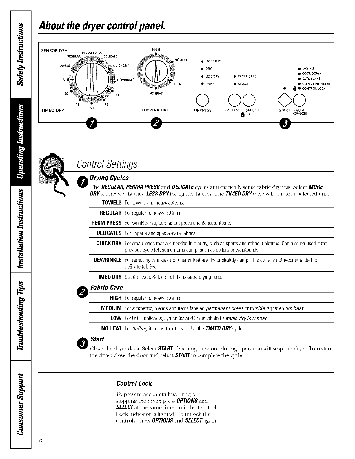
Aboutthedryercontrolpanel
SENSOR DRY HIGH
TIMED DRY
PERMAPRES
45
DELICATE
,o.,,.0 O0 O0
60
TEMPERATURE DRYNESS OPTIONS SELECT S_ MUSE
ControlSettings
00rv',,.Cvo'e.
File REGULAR,PERMAPRESSand DELICATEcyclesaummaticall7 sensefi,bdc dv,'ness.Select MORE
DRYR,r huaxiur fhbri_s, LESSDRYR,r lighter fhbrics, rI'|l_'TIMEDDRY(y(Iu will lun for a sele<led lime.
TOWELS Fortowelsandbeavycottons.
REGULARForregularto beawcottons.
PERMPRESSForwrinkle-free,permanentpressanddelicateitems.
DEUCATESForlingerieandspeciabcarefabrics.
MEDIUM • MOR£DRV
• DRY • DRYING
• LE_DR¥ • EXTRACARE
• DAHP • SkGNAL • CLEAN UNT FILTER
• COOL DOWN
• EXTRA CARE
• 8 • CONTROL _CK
_SJ CANCEL
QUICKDRY Forsmallloadsthatareneededinahum/,suchassportsandschooluniforms.Canalsobeusedifthe
previouscycleleftsomeitemsdamp,suchascollarsorwaistbands.
DBNRINKLEForremovingwrinklesfromitemsthataredryorslightlydamp.Thiscycleisnotrecommendedfor
delicatefabrics.
TIMEDDRY SettheCycleSelectorattbedesireddryingtime.
Fabric Care
HIGH ForieguJartobeavycottons.
MEDIUM Forsynthetics,blendsanditemslabeledpermanentpressor tumbtedrymediemheat.
LOW Forknits,delicates,wntbeticsanditemslabeledtumbledrylow heat.
NOHEAT Forfluffingitemswithoutheat.UsetheTIMEDDRYcycle.
o Start
Close th< dl>er dool: S_'I_'_1 STARTOpuning 1he 4,:,_n-during op<mlion will stop th_ &}er. "I;_reslm-t
Ih{: (hT_'( 1_ close lhe door _]lldselecl STARTtocomplete 1heQ'cle.
Con_olLock
rl_(}prevent accidentally strutting or
stopping the &Tel, pru,,s OPTIONSand
SELECTatthe same fim_ until the Control
Lock indicator islighted. To unlock the
controls, press OPTIONSand SELECTagain.
6
Aboutyourdryerfeatures.
Signal Option
When th(' signal is on it will soun(ljust
b(f'ore the end ot the (vole to remind
you to remove the clothes.
It the dried load cannot be removed
promptly during the cycle, the Cycle
Selector will advance to tile EXTENDED
COOLOOWNsetting. k nh(ated tumbling
contimles during EXTENDED COOL DOWN
and WRINKLE CARE (on some models)
for 40 minutes to help reduce wrinkling.
When the CYCLESIGNAL is OVl,it will
sound briefly ev(ry five minutes as a
reminder to remove the load.
Wrinkle Care
l_s_. this _q)tion 1o minimize the wrinkles
in clothes. It l)rovid(s al)proximalel 3 15
minules of no-heat tumbling a_lt,r the
clothes are (h);
This option can onl 3 be used with the
PERMA PRESS and DELICATEcycles.
NOTE:
• ffitems are removed before the end of
the cycle, press the CANCELbutton twice.
• Remove garments promptly at the sound
of the signal Place clothes on hangers
so wrinkles won't set in.
• Use the Cycle Signal especially when
drying fabrics like polyester knits and
permanent press. These fabrics should
be removed so wrinkles won't set in.
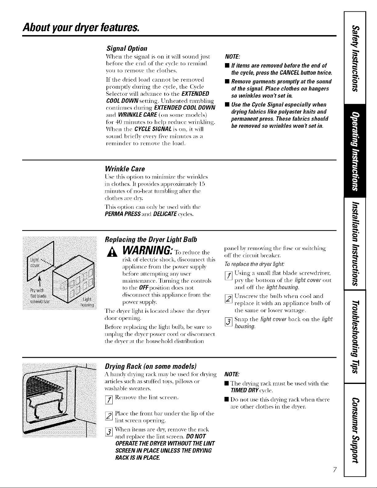
Replacing the Dryer Light Bulb
WARNING:
xisk ot clc(tri( shock, clis(olmt'ct this
appliance from the power suppl)
befim-e attempting any user
mainmnance. "Iilrning the controls
to the OEEposition does not
discolmect this al)pliance fr_nn the
p+_wer SUl)pl>
The (hyer light is located above tile (hy(r
door opening.
Beti)rt +replacing the light bulb, be sure to
unphlg the (h) er i)ower cord or disconne(t
the dt)er at tile hous(h(_l(I distlibution
Dryhlg Rack (on some models)
A handy (hTing ra(k may I)e used fi_n"(h}iv_g
articl( s such as stutt_ d lo?s, pillows or
washal)h, sw( alcl-_.
[_ ]_.elllove Ihe lint s(reen.
[_ Place th< fronl bar under the lip of th<
linl screen OlXning.
[_ When it(!ms are (hT, remov( th{ i'ack
_tll(lreplace lh(: lira scr((n. DONOT
OPERATETHEDRYERWITHOUTTHELINT
SCREENIN PLACEUNLESSTHEDRYING
RACKIS INPLACE,
panel 1)y r_ moving th( fuse or swilching
off Ill(! circuit 1)reakeL
Toreplace fl7e dryer fight:
[_ L sing a small flat blade screwdriv( r,
l)ry the l)olloll] Of the light cover out
and off the fight housing.
[_ 1_nscr(w lh(bull) wh(n cool and
r(l)lace il wilh an appliance bulb of
1he same or lower wattage.
[_ Snap the fight cover I)ack on lh( fight
housing.
NOTE,"
• rI'he (h3ing r,_ck must be used with the
TIMEDORgt)cle.
• [)l_ llOt fist' this dl3ing m(k when there
are other clothes in the dmq:
Loadingand usingthedryer.
Always follow the fabric manufacturer's care label when laundering.
SortingandLoadingHints
.'_',a general lulc, if dothes aru sorted properly for the washm, [hcy are sorwd properly I_br the ill)el;
Do not add fabric softenersheets onced_eload has becomewarm Theymaycause fabricsoftener stains
Bounce®FabricConclltionerDryerSheetsbavebeenapprovedforusein all GEDryerswhenused/Raccordance
with the manufacturer_instructions
Do not overload. Thiswastes energyand causeswrinkling
De not dry the following items: fiberglassitems, woolens,rubber-coateditem& plastic'&items with plastic"trimand
foam-filled items
CareandCleaningof theDryer
The Exterior:'_,%)e or dust an) spills or washing
compounds with a damp cloth. Dwer control panel
and finishes may be damaged b) some laundl 3
pretl_eatlllellt soil and stain lelllOVel ])lodtlctS.
Apply these products away flom the dlTe_; The
fi_bric mav then be washed and dried normally
Damag_ to your d_?er caused by thes_ products is
llOt COV( l't*d bv VOl/l" w}II'I_IIID,\
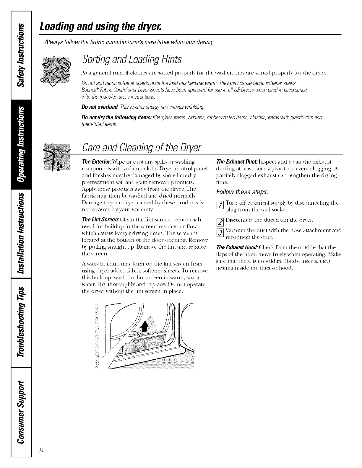
The Lint Screen: Clean the lint screen before each
use. Lint buildup in the screen restricts air flow,
which causes longer &3ing times. The scre_ n is
located at the bottom ot the door opening. Remove
by pulling straight up. Removc the lint and replace
t]l( SCI'( on.
A wax}' buildup may form on the lint scwen flom
using d_Ter-added thbric so[tenor sh_.el,,. "I'(I renlovc
this buildup, wash the lint sort en ill wmm, soapy
watel: DI3 thoroughly and replace. Do not op< l-at_
th_ dDer x_ithout the lint scr_ en in place.
The Exhaust Duct: h]specl and d(an the exhatlSl
duclillg _lt least OllC(t _/ y(_/l" it) l)l'eVelll dogging. A
partially dogg_ d <xhaust C_]lllengthen the dlying
tim_.
Follow these steps:
[_ "l'/l111()It ele(trica[ supply by disconnecling Iht
plug fl-om the wall socket.
[_ I)iscomlect lhe dtlCI flOlll the dl3'er.
[_ X{tCIlIlIII th(: dtlcl with lhe lies( atta< hment and
1"(}(O1111(}(1the (]IlC[,
TheExhaustHood:Clmck Item lh{ outside that the
flaps of lh(? hood mo',e hedy when operating. Mak(
sure lhal there is no wildlife:: I)irds, insects, etc.)
nesting inside file duct or hood.
8

Installation
SpacemakerDryer
Instructions
Model DSXH47
I ffyouhaveanyquestions, ca//800.GE.CARES(800.432.2737)or,_ito,,:Wet,siteat:ge.com I
BEFORE YOU BEGIN
Read these instructions completely and carefully.
• IMPORTANT - S_,_e,h,se
instrucuons fL,r local inspeclor's usc.
• IMPORTANT - Obs_,,e_,n
gOV( l-llil]_ (70(I(s alld or(lillall((s.
• Note to Installer - P,e sure lo leave rials*
illStl'tlcliOllS with lh( Consumel;
• Note to Consllnler - Keep lhese illstru(tions
fk)r f'uture ref_r(mce.
• Skill level - Instalhltion of this applian(,_ requires
basic me( hani(al _llld electri(al skills.
• Completion time - 1-'_ hour_
• F'roper installatioll is lh( r_sponsil)ility ot lh(
installer.
• t ro(hl(I lailur( (lu( to imf)rop( r installalion is not
covel-(_d llll(l( 1- [l](_ _Tal-l-all['_L
IN THE COMMONWEALTH OF
MASSACHUSETTS
• This producI must be installed by a licens(d
plumber or gas fitte_
• When using ball-type gas shut-offvalves, they
shall b( th( T-handle type.
• A fh'xible gas (onnc(tot, when used, must not
(x(e(d 3 t_et.
FOR YOUR SAFETY:
__ WARNING
This dlyer must b( exhm/sted to the ouldoors. [se
only rigid m(tal or t]exible metal 4" diamelt.r ductwork
ti-_rexhausting to the oul.side, l Jse out} ri_-id lnetal 4"
diameter ducn_'ork inside the dlycr cabinet.
• Nev(r us( I}laslic or other combustil)l( ductxvork. St(
Exhausting st ( tion.
• This al)plianc( musl be l)rop(rly grounded and
install¢d as d(sclib(d in these h7statl,°,tio/7Instruction&
• Do 11ol install or stove aplMiance in an ar(a where it will
be exposed o x_a eriweath_ L Se( Locatio 7 o(Your Drgor
S( clioll.
The National Fuel (his cod( restricts installations ot
gas appliances in garages. They must l)e 18" (45.7 cm)
otl tile ground _lnd prolt'ctcd trom xt'hicles by a
barrieL Se( Location o( Your Dryor section.
• The electrical s_rvice tothe (h'+( r llnlsI COllfol 111x_ith
local cod¢s and ordinauc(s and the latesl ( dilioi, ,.)f the
National Elecnical Cod(, ANSI/NFI_.R 70.
The _&'_service to the dz_'er must contktrm with local
codes and cmdil_ances or the latest edition of' the
National Fu_l (;_s Cod_ ANSI Z223.1. The gas (hy(r is
d(signed under ANSI Z 21.5.1 fl)r home use only. This
dlTer is not r( commended tiw commercial apl)lications
_,llCll aS l-t'stall l_llltS o1 beallt_" salollS.
9
Installation Instructions
TOOLS AND MATERIALS
YOU WILL NEED
F1 Phillips head screwdriver
0 .\t!justable pliers (a(!just leveling legs)
F]I C_llpenttT'S lexel
V] Flat or swaigbt blade screwdriver (ma} b( needed
for coM su;fin relie0
V] Duct tape
F] Ri_M or t IAisted flexible metal 4" (10.2 cm) duct
V1 Vent ho_M
FI 1/4" nut diner (remow' terminal block access
c(wer and install toM) (ELECTRIC DRYER)
F1 Pipe thread s_aler (GAS DRYER)
V1 L IAismd strain reli_ f (may be supplied
with cord)
V3 L IAiswd 30A, 240"L 3-wire, #10 AWG minimum
conducu)r power coM (existing structln-( )
F1 [ Misted 30A, 240";, 4-Mrc, #10 AWl;
minimmn conduclt_r po'_xer COld is,required
(n_w consmlction)
PREPARING THE INSTALLATION SITE
AND UNPACKING YOUR DRYER
1,
Prepare tile ar_a and exbaust tor installation
of lhe new dlyel;
2.
Check to be sure that the existing <xternal
exhaust is clean and flint it m_els auached
installation specifications.
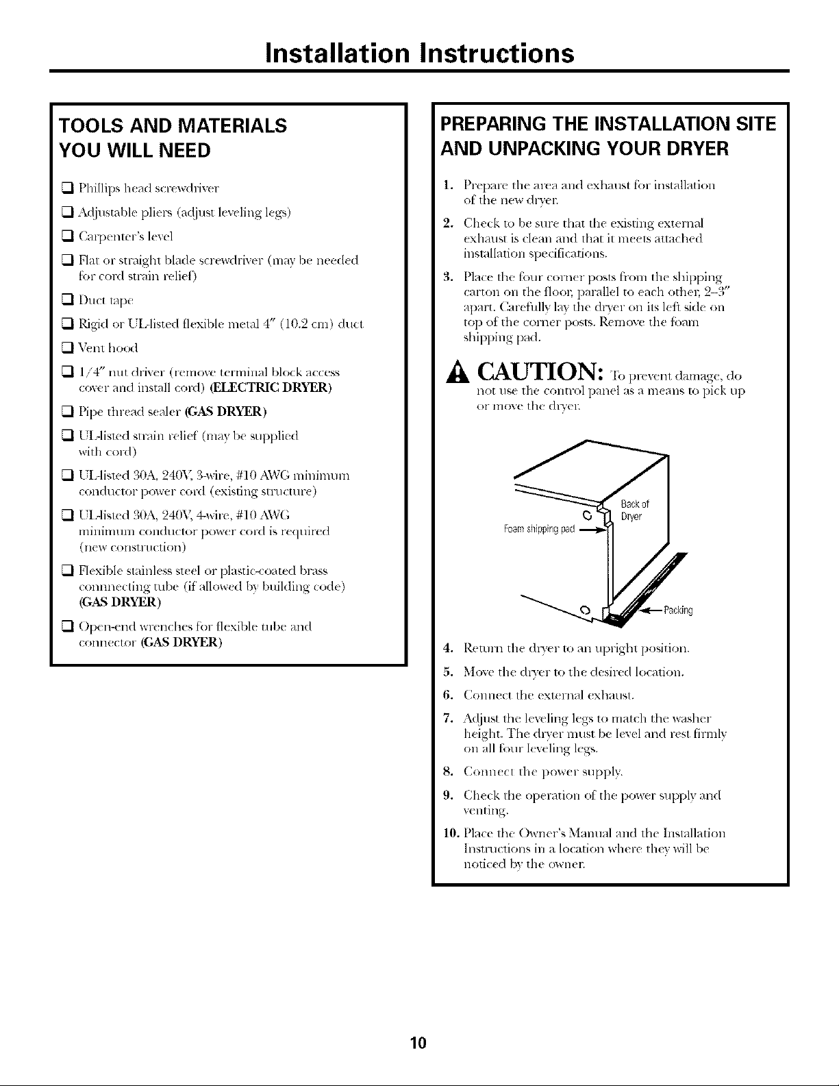
3,
Place lhe four comer posls f'lxm_tile shipping
carton on tbe flool; parallel to each othen 2-3"
apart. C,arefillly la7,tile (hler on its left side oil
top of tim comer posts. Remove tile tbmn
shipping pad.
.& CAUTION: "Ib prevenl damage, do
not use tile control panel as a re(arts 1opick up
or move tbe &wel:
F] Flexible staink ss steel or plastk-coated brass
connnecting robe (if' allow(d by building code)
(GAS DRYER)
V] Open-end wrenches tot flexible robe and
connector (GAS DRYER)
4. Reunn tile (hTer 1o all uprigbt position.
5. Move the dlTer 1o tile desired location.
6. Collll(Ct tim ext(lnal exbaust.
7. A_!just tbe leveling legs to match tbe washer
height. The dlwer nlust be level and rest tirmlv
on all four kw ling k_*.
8. Conn(cl tile pow(r supply.
9. Check the operation of lhe power supply and
venting.
10. Place the Owner's Manual and the Installatkm
lnsnuctions in a location where thev will be
notic(d b3 tile ownel;
10
Installation Instructions
Read these instructions completely and carefully.
ELECTRICAL CONNECTION
INFORMATION FOR
ELECTRIC DRYERS
^_ WARNING - "r,,,-e,lu.,h,,-i¢,,_
fir_, cle,.:tric shock or p_ rsonal il!jury:
• DO NOT USE AN EXTENSION CORD _VITH
THIS APPLIANCE.
• THIS APPLIANCE MUST BE PROPERLY
GROUNDED.
Tiffs dryer mttst be electrically grounded in accordance
with local codes mad olxlinances, or in the absence of local
codes, in accordance with the NATIONAL ELECTRICAL
CODE, ANSI/NFPA NO. 70.
Electrical Requirements
• This dl_,er must be colmected to a 20SV or 24(W
indivi(h/_d brancla cir( uit, protected by .'I0-;unp circuit
breakel_ or time<telay fuses.
• Pow(r SUl)ply: 3-wire 24(,Lvoh, singlc-phase, t_)-I tz,
z_dleFll_t lillg CII IT(:111.
• I se COl}IX r conduclol.'s only.
ELECTRICAL CONNECTION
INFORMATION FOR GAS DRYERS
_k WARNING - l_>,-,.,1..,h,,-isko,
fir<, _leclric shock or l)ersonal injm-y:
• DO NOT USEAN EXTENSION CORD ORAN
ADAPTER PLUG WITH THIS APPLIANCE.
• DO NOT, UNDER ANY CIRCUMSTANCES, CUT OR
REMOVE THE THIRD GROUNDING PRONG FROM
THE PO_rER CORD.
This dryer must be electrically grounded in accolxtance
Mth local codes mid olxtinances, or hi the absence of local
codes, in accordance with the NATIONAL ELECTRICAL
CODE, ANSI/NFPA NO. 70.
Electrical Requirements
• This cider must be supplied with 120x,, 60-tlz,
and comlecled to a properl 3 grounded branch
circuit, protected I)ya 15- or 20-mnp circuit breaker
or lime-delay fuse.
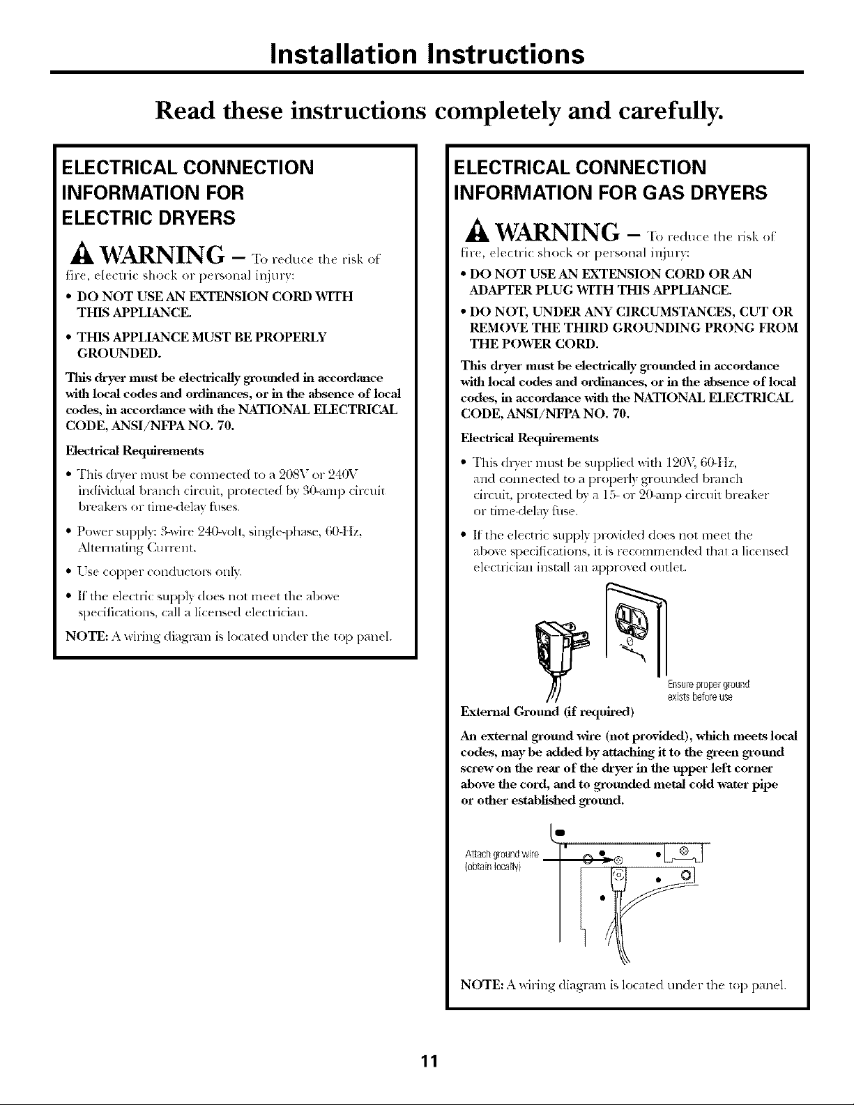
• lithe el(ctric supply provided does not meet the
above specifications, it is recommended thai a licensed
<leclrician inslall an approved outlet.
• lithe ele(tri( supl)lx does not meel tile aboxe
sp_ cifications, call a licensed electrician.
NOTE: A wiring diagram is located under the top l)anel.
_[nsure properground
existsbeforeuse
External Ground (if required)
An extertml _ound wire (not provided), which meets local
codes, may be added by attaclfing it to the _en _otmd
screw on the rear of the dryer in the upper left corner
above the cord, mid to gTounded metal cold water pipe
or other estabh'shed grotmd.
L"
Attach groundwire
(obtainlocally}
NOTE: A wiring diagram is locat{ d under 1he top panel.
11
Installation Instructions
EXHAUST SYSTEM
REQUIREMENTS
Use only 4" (10.2 own)diameter (minimum) _fid metal
duct for best performance, ol- flexil)le m(la] duct, and
approved vcnt hood whkb has sxdng-out dmnpers thai
open when th( cheer is in opel;ition. When the dlTer
slops, th_ dampers automatically (:lose 1o pFevelll dl-,ifls
and the enmmce ot ins(cts and F(KIeIIIS.To avoid
restricting th( oullet, maintain a minimum of 12"
(30.5 cm) clem-,u_ce 1)elw_en the vent bood and the
gFOlllld OF an} oth{r obstFtlCtiOll,
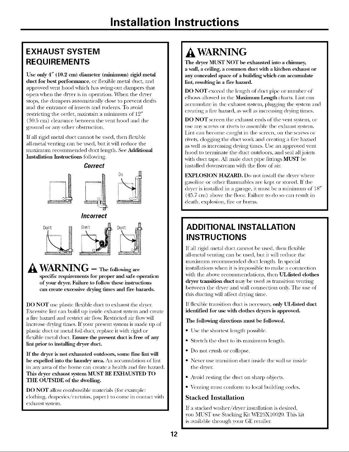
It all rigid metal duct cannot be used, then flexible
all-metal w nting (an be used, but it will reduce the
maximum reconmmnde d ducl length. See Additional
Installation Instructions _bllowing.
Correct
Incorrect
.4, WARNING
The dryer MUST NOT be exhausted into a chimney,
a wall, a ceiling, a common duct with a kitchen exhaust or
any concealed space of a building which can accumulate
lint, resulting in a fh'e hazard.
DO NOT <xceed the length of duct pip¢ or number of
ell×ms allowed in the MaxinlUnl Length (:haFts. Lint can
accmnulatt in lh_ exhaust,ysmln, phlgging tile _y_mm and
creating a fire hazald, as well as increasing d135ng times.
DO NOT scre_ n the exhmlst ends (A:the vent s}_tem, or
IlSL* HII} SCI'C_VS O1" rivets tO _tss('lnblc _hu (X]lHllSt sxst('ln.
Lint can be(onle (might in the s(reen, on the s(re>,s or
livets, clogging the duct work and creating a filv hazaM
as well as increasing dwing times, tse an approved wnt
hood to terminate the duct outdoor% and seal all joints
with duct rope. All male duct pipe fittings MUST be
installed downstremn with the flo_ ot all:
EXPLOSION HAZARD. Do not install the dwer where
gasoline or other flammables are kept or stored. It the
dwer is inslalled in a garage, it must be a minimum of 18"
(45.7 cm) above the flool: Faihlre to do so can resuh in
death, explosion, fire or burns.
jDon't
WARNING - Thefidlowing are
spedfic requirements for proper and ,'safeoperation
of yoar dryer. Failure m tbllow these instructions
can create excessive drying times and fire hazards.
DO NOT use plastic flexible duct to exhaust tile:dlTtq:
Excessive lint can build up inside exhaust sT,smmand cream
a ill> hazmxl and restrict air flow. Restrict_d air flow will
increa_*, dDing tim_ s. If }x)ur p_esent system is made up of
plastic duct or metal fi.filduct, replac{ it with rigid or
fl(xible metal duct. Ensure the present duct is free of any
lint prior to installing dryea_duct.
If the dryer is not exhausted outdoors, some Fme lint _11
be expelled into the latmdry area. An accumulation of lint
in any area of the home (an crealc a heahh and fire hazard.
This dryer exbattst system MUST BE EXHAUSTED TO
THE OUTSIDE of the dwelling.
DO NOT allow combustible malt*rials (fi:)rexample:
clothing, draperies/curtains, paper) 1o come in contact xxith
exhmlst s}"-;leHL
ADDITIONAL INSTALLATION
INSTRUCTIONS
It all rig{d metal duct cmmot 1)eused, then flexible
all-metal xenting can be used, but it will reduce the
maxilnum r( commended duct length. In q)ecial
installations when it is impossible to make a connection
with the above recommendations, then UL-llsled dothes
dryer transition duct lnay be used as lransition venting
between the @yer alld wall conn_ cfion onl). The use ot
this ducting will at'Ib(t (hTing time.
It flexible transition duct is n_cessaQ; only ULlisted dtmt
identified tbr use with dothes dryers is approved.
The following directions mttst be followed.
• Use the shortest length possible.
• Stlx b.b the duct to its maximum length.
• Do not crush or collaps(.
• Nexer use mmsition duct inside the wall or inside
the <hTel:
• Axoid resting the duct on sharp objects.
• Venting must confi)un to local building codes.
Stacked Installation
If a stacked washer/@Ter installation is desired,
vou MUgI" use Stocking Kit "_,T25X10f12fl. This kit
is available through your GE retailel:
12
Installation Instructions
EXHAUST DUCTING LENGTH
The exhaust s}_mm shouM be inspecled and cleaned a
lllil]illlill]l 01"evel)" year with normal usage. The moa th(
dlwer is used, the more ofi_n you should check tile exhausl
sx_mm and _nt hood tot prop( r operation.
• DO NOT assemble th( duct work with thstenep, that
extend into the duct. They will s(lve as coll_ ction points
fi:,r lint.
• Instflation - Ductwork which runs through an unheated
area or is near an air conditioning duct should be
insulat(d to rcdu(x condensation and lint buildup.
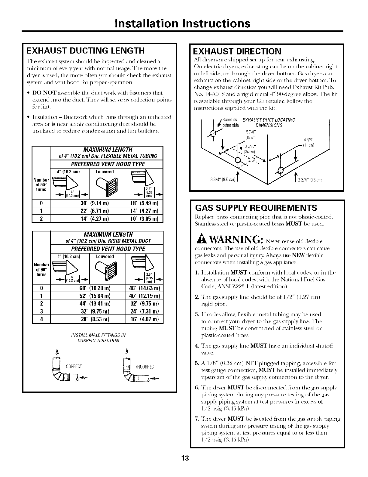
MAXIMUM LENGTH
of 4" (10.2cm) Dia. FLEXIBLEMETALTUBING
PREFERREDVENT HOOD TYPE
4"(102cm) Louvered
of 90°
Numbelturns_1 I
0 30" (9.14 m) 18' (5.49 m)
1 22" (6.71 m) 14' (4.27 m)
2 14' (4.27 m) 10' (3.05 m)
of90°
Numbelturns_1 I
0 60" (18.28 m) 48' (14.63 m)
1 52" (15.84 m) 40' (12.19 m)
2 44' (13.41 m) 32' (9.75 m)
3 32' (9.75 m) 24' (7.31 m)
4 28' (8.53m) 16" (4.87 m)
4" (6.35
i]l,,q(lO.2cin)l-qlF- ---]l,,- ci,,) "_"
I 2.5" I
MAXIMUM LENGTH
of4" (10.2cm)Dia. RIGIDMETALDUCT
PREFERRED VENT HOOD TYPE
4"(10,2cm) Louvered
4,,
°"ll ....I
INSTALLMALEFITTINGSIN
CORRECTDIRECTION
(6.35
2.5" I
EXHAUST DIRECTION
All (hyers m-e shipped set lip till real- exhmlsling.
On electric (Iwers, exhmlsfing can be on the cabinet right
or left ski(, or through tile (hyer bottom. ()as dlyers (nil
exhmlst on the (abinet right si(l( or the dlwer bouom. To
dmnge exhaust dire(don )ou will need Exhmlst Kit Pub.
No. I_A018 and a rigid metal 4" 90<legree elbow. The kit
is available through }our GE retailei: Follow the
instructions supplied with the kit.
Samo aS
/ _/other side EXHAUSTDUCTLOCATING
fl'l 'l 57/_'
33/4" (9.5cm)
DIMENSIONS
(15cm) 43/8'
GAS SUPPLY REQUIREMENTS
P.cpla(( hi'ass (Ollile(tiilg pipe that is llOt plastic-coated.
Stainless ste(l or l)lastic4"oated bl-<l_,sMUST be tlS((1.
WARNING: ,,l<lflexible
(OllIl('('tOl'% "I'ht" use ofoM flexible COlllR>(lOiS (all ( _tl/qe
gas leaks and personal il!iuv,. Nways use NEW flexible
connectors when insmllillg a gas appliance.
1. Installation MUST confoml with local codes, or ill the
absence of local codes, with the National Fuel (;_s
Code, ANSI Z223.1 (lawst edition).
,
The gas supply line should b( of 1/2" (1.27 cm)
rigid pip(.
3.
If codes allow, tlexible metal tubing may be use(I
to connect your (hwer to the gas supply line. The
robing MUST be constructed of stainless st(el or
plastic-coamd bl-_lss.
4. The gas supply line MUST hay( an individual shutoff
xGIIv( .
5. A 1/8" (0.32 cm) NPI' plugged tal)ping, accessible tor
test gmlge c(mnection, MUST be installed immediately
upstr(am ot file gas supl)ly connection lo the dlyel:
6,
Th_ dlTer MUST be disconnecled flom the gas supply
piping _)slem du ring any pressure testing of the gas
supply piping s}_tem at test pressurcs in (xcess of
1/2 psig (3.45 kPa).
7.
Th( dryer MUST be isolated from the gas supply piping
sxstem during any pressure testing of the gas SUpl)ly
piping _?stem at It:st pressures ((lual to or kss than
1/2 psig (3.45 kPa).
13
Installation Instructions
LOCATION OF YOUR DRYER
Do Not Install the Dryer:
1. Do not install tile dryer ill ;In area _xl)_e(I to dril)ping
water or outsid( _t_ather Colldilions.
2. Do not install the dryer in an area whert= it will come
in contact with curtains, dF4pes or anytlaing that will
obstruct th_ flow of conll)ustion and ventilation all:
3. Do not install the dryer (m carpet.
Floor MUST be solid with a maximum slope
of 1" (2.54 cm).
Undercounter Installation:
If an undercounter installation isdesirt,d, a custom-._ized
countertop is l-tquired (36" to the uudel',ide of the
countertop). No spe( ial dl)'_ r top is reqtfired.
Installation in Recess or Closet:
1. This dis'or MUST b_ exhausled outdoors.
2. No other fu_l/)urning appliance shall be insmlk d in lhe
sanlc cl_:_el ;asthe GAS DRYER.
3.'_i_tn- dl3'er n_eds th_ spac_ around it for prop_ r
_ ntilalion. DO NOT INSTALL YOUR DRYER IN A
CLOSET WITH A SOLID DOOR.
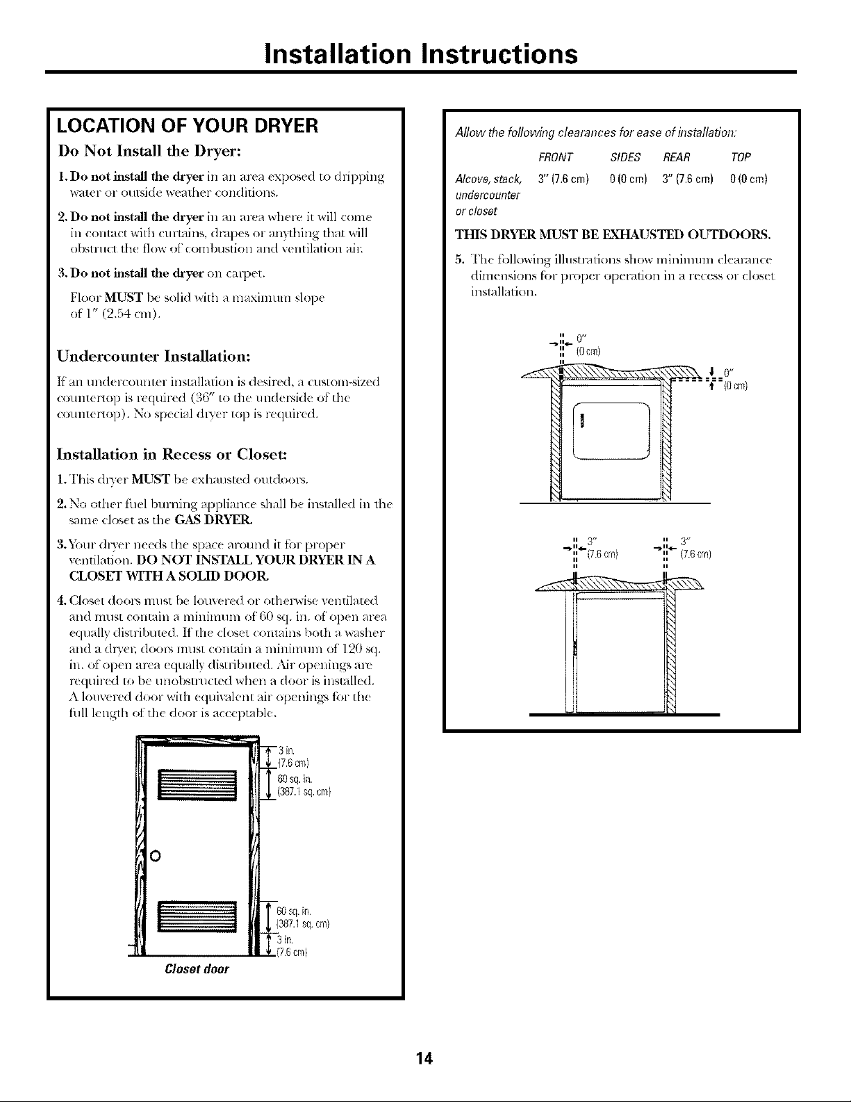
Allow the following clearances for ease of installation:
FRONT SIDES REAR TOP
Alcove,stack, 3" (7.6cm) 0 (0cm) 3" (7.6cm) 0(0cm)
UITdOKCOURtor
or closet
THIS DRYER MUST BE EXHAUSTED OUTDOORS.
5. The ibllowing illusu-mions show minimum clem-4nce
dimensions fi_r proper operation ill a re(ess or closet
installation.
II 0,/
" {Ocm}
ii /J ii 3/,
._1. II.r_ 3 ..,_ I1_-
" (78cm) " (7.6cm)
4. Closet dool-s must be louvered or othelsvise ventilated
and must contain a minimum of 60 sq. in. _1'open ar(a
equally distribumd. If the closet contains both a washer
and a dlT'en dooc_ lllust contain a minimum of 120 sq.
in. ot open area _qually disuqbut_ d. Nr openings arc
required t_ be unobsnalcmd when a door is installed.
A louvered door with equiv_llent air openilags R_r th_
fllll lenglh ot th_ door is acceptable.
- 3in.
7.6cm}
(387.1sq.cm}
0
! ] (387.1sq cm)
(7.6cm)
Closet door
14
Installation Instructions
MOBILE HOME INSTALLATION
1.Dlyer MUST be exhausted oulside (outdoor% not
beneath the mobile home) using metal (lu(ling lhat will
not support combustion. Metal ducting must lye 4"
(10.16 cm) in diameter with no obstructions. Rigk/metal
duct is pl>fbrred.
2. ltlhe dlyer is _xhausted through 1he t]oon 1he exhaust
system MUST NOT lel-lllill_71[ebeneath Ill{!mobil_
home. "l_!rmination MUST be sectlr( Iv f_lSlelled lo Ih(
l]]O/)i[( h()l]](_ S[l'[l(tl]l'(.
3.When installing a gas dwer into a mobile home, a
provision must be made for out',ide makemp ain This
provision is to be not less than twice the ar(a of the dlwer
exhm_st outlet.
4. Gas (hyers MUST/)( fasten( d to th( lloor using Mobile
I lame Installation Kil Pul). No. 14-D34(;-33.
5.See the ExhaustSystemRequirementssection for other
important xenling inR)rmation.
6. Installation MUST confi_)Hnto current Mamdactu red
Home Construction & Salbty Standard (which is a
Federal Regulation Title 24 CFR Part 32-80) on
when such smn(/m-d is not applicable, with Americm_
National Standard tbr Mobile Homes, ANSIiNFE\ No.
501 g.
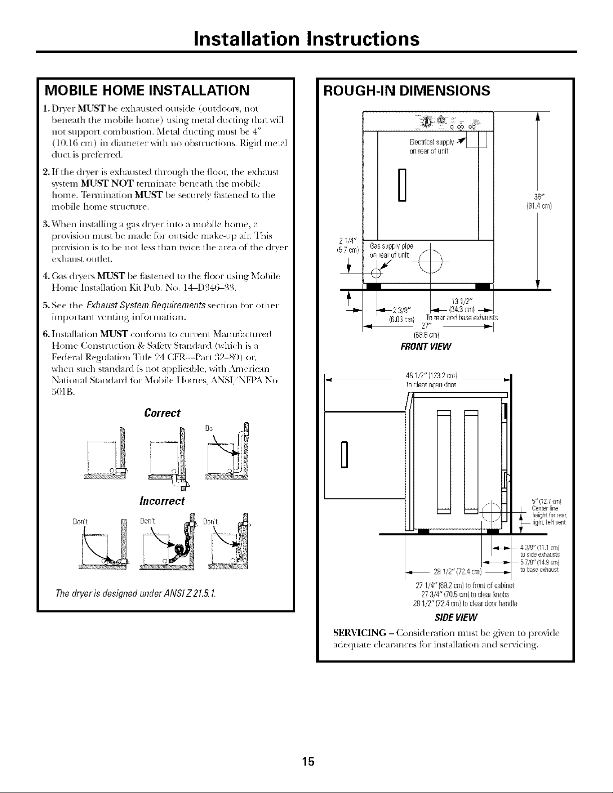
ROUGH-IN DIMENSIONS
..... :: V =
Electricalsupply < _
onrear0tunit
21/4"
(5.7cm) f unit
Gassupplypip_
'Z
I I
23/8" _ (34.3cm)+
Torearandbaseexhausts
27" 4=,,-I
(68.6cm)
FRONTVIEW
481/2"(123.2cm)
toclearopendoor
36_"
(91.4 cm}
i
Correct
Incorrect
Don't
Thedryeris designedunderANSIZ21.5.I.
n
5"{12 7 cm}
Centerline
\
_28 1/2"(72 4 cq_}
27 1/g'(69.2 cm}tofrontofcabinet
273/4" (70.5cm)to clearknobs
281/2" (72.4cq_}to dear doorhandle
SIDEVIEW
SERVICING- ()msidemlion must be gixen to l)roxid(
adequate cleal'all(Test'OFinstallation and s(rvicing.
heightfor rear,
4 3/8"(111 cm)
tosideexhausts
to base exhaust
15
 Loading...