

Page 1

GE
Digital Solutions
Pressure Automated Calibration Equipment
Safety Instructions and User Guide - K0467 Revision A
English EN Español ES
Français FR Português PT
Deutsch DE Русский RU
Italiano IT
中文
PACE Pressure Indicators
ZH
© 2010 General Electric Company. All Rights Reserved. Specifications are subject to change
without notice. GE is a registered trademark of General Electric Company. Other company or
product names mentioned in this document may be trademarks or registered trademarks of their
respective companies, which are not affiliated with GE.
Page 2

5
6
3
4
A
B
C
7
22V to 26V
22V to 26V
XXXX
XXXX
XX
ANALOGUE 1
CONSULTHANDBOOK
CONSULTHANDBOOK
22V to 26V
ANALOGUE 1
CONSULTHANDBOOK
D
22V to 26V
ANALOGUE 1
VFC 1
15
CONSULTHANDBOOK
2
1
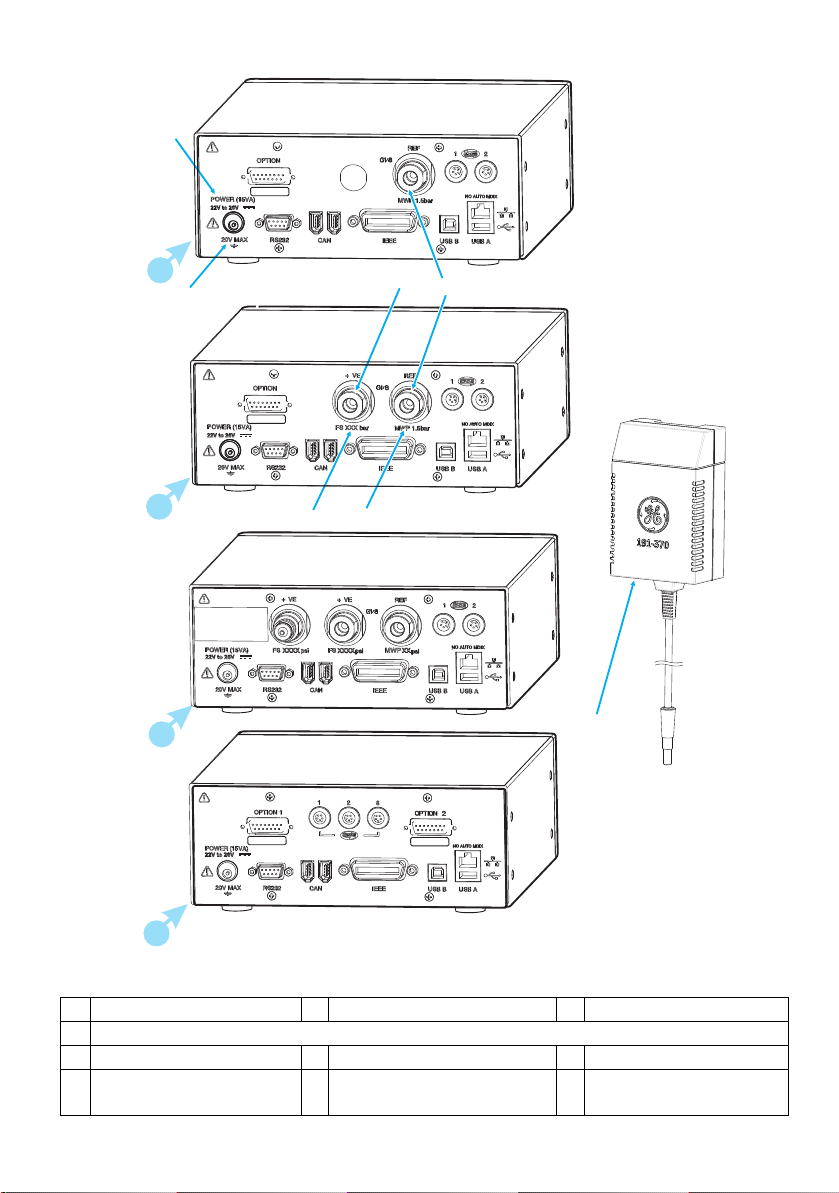
Figure 1
A Single port instrument B Two port instrument C Three port instrument
D Remote sensor instrument
1 Power supply connector 2 Electrical rating 3 Pressure port
4 Pressure port 5 Maximum working pressure 6 Pressure full-scale (range)
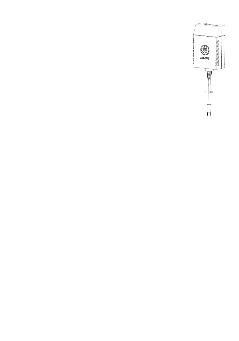
7 Power supply adaptor (see packaging list)
K0467 Revision A 1 [EN] English
Page 3

1 Introduction
The PACE Pressure Indicator measures both pneumatic and hydraulic pressures and displays, on a
colour touch-screen, the measured pressure and instrument status. The touch-screen enables
selections and settings in measuring modes. The instrument can be operated remotely through
communication interfaces.
1.1 Safety
The manufacturer has designed this equipment to be safe when operated using the procedures
detailed in this manual. Do not use this equipment for any other purpose than that stated, the
protection provided by the equipment may be impaired.
This publication contains operating and safety instructions that must be followed to make sure of
safe operation and to maintain the equipment in a safe condition. The safety instructions are
either warnings or cautions issued to protect the user and the equipment from injury or damage.
Use qualified* technicians and good engineering practice for all procedures in this publication.
1.2 Pressure
Do not apply pressures greater than the maximum working pressure to the equipment.
1.3 Toxic Materials
There are no known toxic materials used in construction of this equipment.
1.4 Maintenance
The equipment must be maintained using the procedures in this publication. Further
manufacturer’s procedures should be done by an authorized service agents or the manufacturer’s
service departments.
1.5 Technical advice
For technical advice contact the manufacturer.
*A qualified technician must have the necessary technical knowledge, documentation, special test
equipment and tools to carry out the required work on this equipment.
1.6 General Specification
Display LCD: Colour display with touch-screen
Operating temperature 10°C to 50°C (50° to 122°F)
Storage temperature -20°C to 70°C (-4° to 158°F)
Ingress protection IP20 (EN60529)
Operating humidity 5% to 95% RH (non-condensing)
Vibration MIL-PRF-28800 Type 2 class 5 style E/F
Operating altitude Maximum 2000 metres (6560ft)
EMC EN 61326
Electrical safety EN 61010-1, UL61010-1, CSA 22.2, No. 61010-1 and IEC61010-1
Power adaptor Input range: 100 - 240VAC, 50 to 60Hz, 660mA. Installation category
II
Pressure safety Pressure Equipment Directive - class: sound engineering practice
(SEP) for group 2 fluids.
Pollution degree 2
Operating Environment Indoor use only. Not rated for use in potential explosive
atmospheres.
[EN] English 2 K0467 Revision A
Page 4

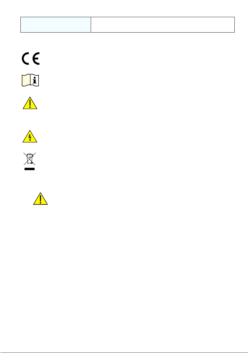
1.7 Symbols
This equipment meets the requirements of all relevant European safety
directives. The equipment carries the CE mark.
This symbol, on the equipment, indicates that the user should read the user
manual.
This symbol, on the equipment, indicates a warning and that the user should
refer to the user manual.
Ce symbole, sur l’instrument, indique que l’utilisateur doit consulter le
manuel d’utilisation. Ce symbole, dans le manuel, indique une situation dangereuse
This symbol warns the user of the danger of electric shock.
Ce symbole alerte l’utilisateur sur le danger de choc électrique.
Do not dispose of this product as household waste. Use an approved organisation that collects and/or recycles waste electrical and electronic equipment. For more information, contact one of these:
- Our customer service department: www.gemeasurement.com
- Your local government office.
WARNINGS
TURN OFF THE SOURCE PRESSURE(S) AND CAREFULLY VENT THE PRESSURE LINES
BEFORE DISCONNECTING OR CONNECTING THE PRESSURE LINES. PROCEED WITH
CARE.
ONLY USE EQUIPMENT WITH THE CORRECT PRESSURE RATING.
BEFORE APPLYING PRESSURE, EXAMINE ALL FITTINGS AND EQUIPMENT FOR
DAMAGE. REPLACE ALL DAMAGED FITTINGS AND EQUIPMENT. DO NOT USE ANY
DAMAGED FITTINGS AND EQUIPMENT.
DO NOT EXCEED THE MAXIMUM WORKING PRESSURE OF THE INSTRUMENT.
THIS EQUIPMENT IS NOT RATED FOR OXYGEN USE.
THE GROUND LEAD OF THE INSTRUMENT MUST BE CONNECTED TO THE AC SUPPLY
PROTECTIVE SAFETY GROUND.
ISOLATE THE POWER SUPPLY BEFORE MAKING ANY ELECTRICAL CONNECTIONS TO
THE REAR PANEL.
K0467 Revision A 3 [EN] English
Page 5
1.8 Packaging
Check the contents of the PACE1000 packaging with the list that follows:
Packaging List - PACE1000
i) PACE1000 Pressure Indicator.
ii) Adaptor, power supply (GE part number 191-370).
iii) User guide and safety instructions, and CD containing the full documentation suite.
iv) Calibration certificate.
1.9 Packaging for Storage or Transportation
To store or return the instrument for calibration/repair do the procedures that follow:
1. Pack the instrument (Ref: K0470, User manual, Reference and Specification, Section
6.13).
2. Return the instrument for calibration/repair complete the return goods procedure (Ref:
K0470, User manual, Reference and Specification, Section 6.12).
2 Preparation for Use
The instrument can be used as a:
• Free-standing instrument positioned on a horizontal surface
• Panel-mounted using the panel-mount option kit (Ref: K0470, User manual, Section 2.5)
• Rack-mounted in a standard 19 inch rack using the rack-mount option kit (Ref: K0470,
User manual, Section 2.5).
For free-standing instruments, the feet on the front of the base can be used elevate the
instrument to a better viewing angle.
Note: Allow a free flow of air around the instrument, especially at high ambient temperatures.
2.1 Connecting the Instrument
WARNINGS
TURN OFF THE SOURCE PRESSURE(S) AND CAREFULLY VENT THE PRESSURE LINES
BEFORE DISCONNECTING OR CONNECTING THE PRESSURE LINES. PROCEED WITH
CARE.
ONLY USE EQUIPMENT WITH THE CORRECT PRESSURE RATING.
BEFORE APPLYING PRESSURE, EXAMINE ALL FITTINGS AND EQUIPMENT FOR
DAMAGE. REPLACE ALL DAMAGED FITTINGS AND EQUIPMENT. DO NOT USE ANY
DAMAGED FITTINGS AND EQUIPMENT.
DO NOT EXCEED THE MAXIMUM WORKING PRESSURE OF THE INSTRUMENT.
THIS EQUIPMENT IS NOT RATED FOR OXYGEN USE.
[EN] English 4 K0467 Revision A
Page 6
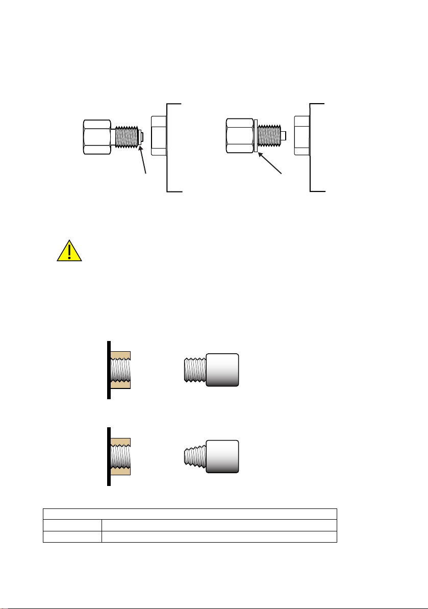
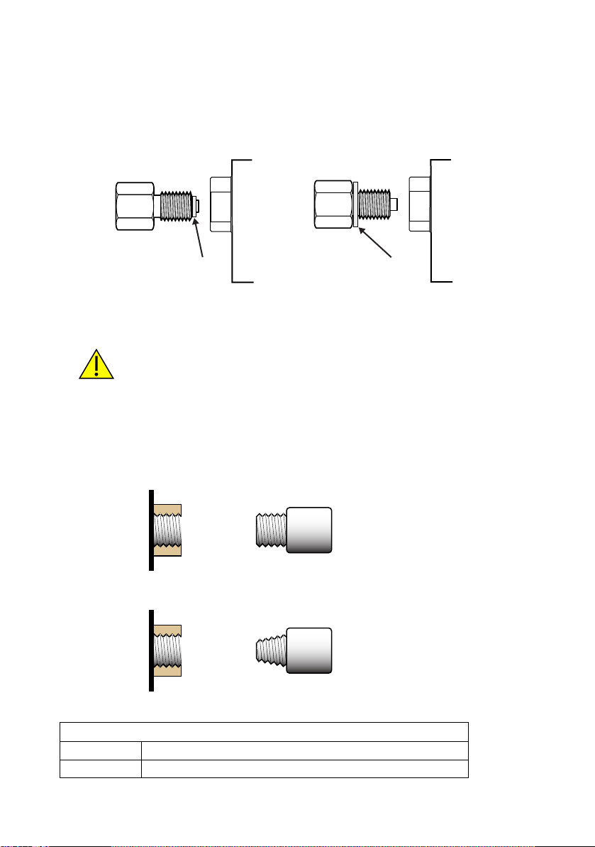
2.2 Pneumatic Pressure (Figure 2)
ISO 228 G1/8 ISO 228 G1/8
bonded seal bonded seal
Recommended method Alternative method below 100 bar
Parallel threads must be used.
Female thread type is parallel thread to
ISO228/1 (DIN ISO228/1, JIS B0202)
G1/8
Tapered threads NOT allowed.
PACE pressure port
PACE rear
panel
9
8
PACE rear
panel
PACE pressure port
1. Refer to the Data sheet for the correct pressure mediums to be used.
2. Connect the Unit Under Test (UUT) to the required connection port.
Note: For instruments with NPT connections, use applicable bonded sealing as shown in figure
below.
Figure 2 Sealing Pneumatic Connections
2.3 Pneumatic connections
WARNINGS
PARALLEL THREADS MUST BE USED. FEMALE THREAD TYPE IS PARALLEL THREAD TO
ISO228/1 (DIN ISO228/1, JIS B0202) G1/8.
TAPERED THREADS NOT ALLOWED.
Connection
Input ISO228/1 G 1/8 parallel threads (DIN ISO228/1, JIS B0202)
Reference ISO228/1 G 1/8 parallel threads (DIN ISO228/1, JIS B0202)
For examples of adaptors (see Page 8).
K0467 Revision A 5 [EN] English
Page 7
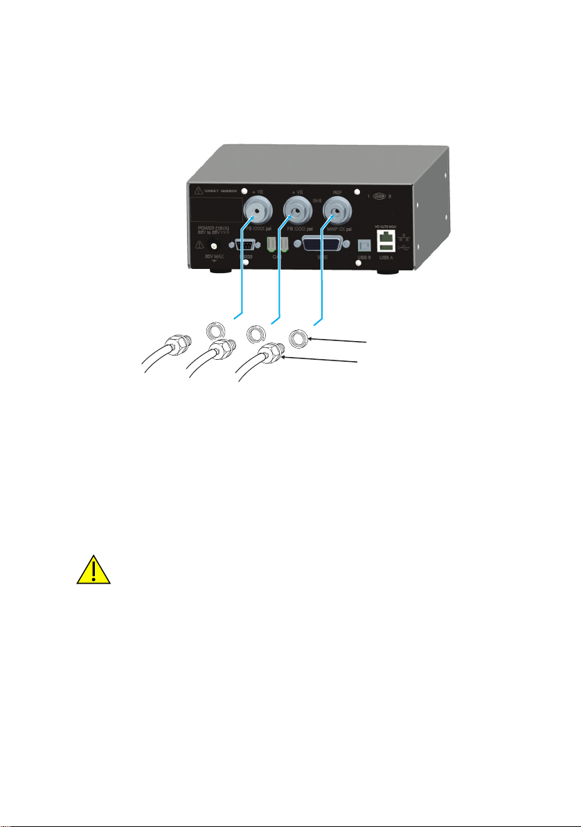
2.4 Input Pressure (Figure 3)
2
1
1) Connector
2) Bonded seal
1. Make sure the user systems can be isolated and vented.
2. Connect the Unit Under Test (UUT) to the output connection port.
Note: For instruments with NPT connections, use applicable bonded sealing (2) as shown
in figure below.
Figure 3 Pneumatic Connections
3 Installation
The instrument connects to the Unit Under Test.
3.1 Input Pressure and Equipment
The pressure should not exceed 1.25 x full-scale or MWP stated on the rear panel of the
instrument.
To protect the instrument from over-pressure a suitable protection device (such as a relief valve or
bursting disc) must be fitted to prevent over pressurization.
3.2 Pneumatic Connection
WARNING
PRESSURE RANGES > 210 bar (3000 psi) ARE ONLY RATED FOR HYDRAULIC USE.
CAUTIONS
Do not exceed the maximum pressures stated in the appropriate Component
Manual for the unit under test.
Reduce pressure at a controlled rate when venting to atmosphere.
Carefully de-pressurize all pipes to atmospheric pressure before disconnecting and
connecting to the unit under test.
[EN] English 6 K0467 Revision A
Page 8

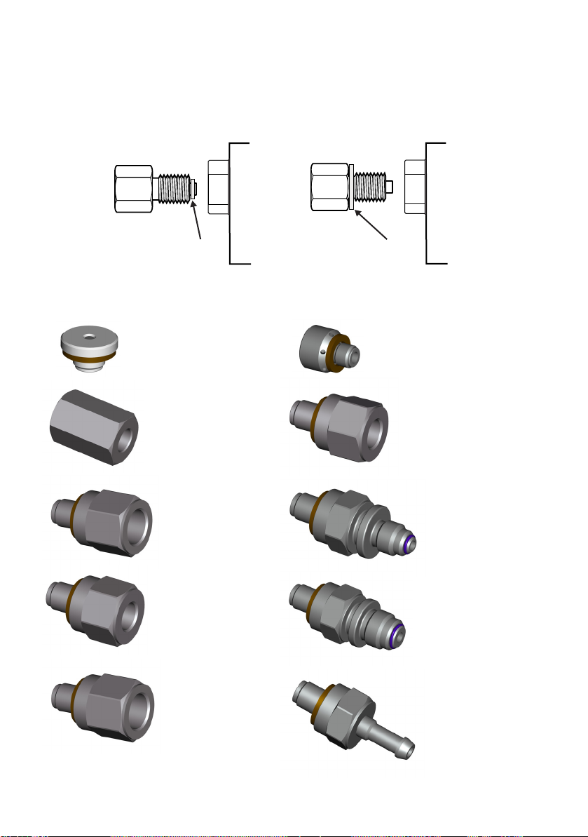
3.3 Connections
ISO 228 G1/8 ISO 228 G1/8
bonded seal bonded seal
Recommended method Alternative method below 100 bar
IO-SNUBBER-1
IO-ADAPT-9/16AUTOC
ISO 228 Male to 9/16 Autoclave
IO-DIFFUSER-1
IO-ADAPT-G1/4
ISO 228 Male to G1/4 Female
IO-ADAPT-1/8NPT
ISO 228 Male to 1/8 NPT Female
IO-ADAPT-1/4NPT
ISO 228 Male to 1/4 NPT Female
IO-ADAPT-7/16UNF
ISO 228 Male to 7/16 UNF Female
IO-ADAPT-AN4
ISO 228 Male to AN4 37° Male
IO-ADAPT-AN6
ISO 228 Male to AN6 37° Male
IO-ADAPT-BARB
ISO 228 Male to 1/4 Hose
1. Switch off the power supply before connecting or disconnecting the instrument.
2. Use the appropriate sealing method for all pressure connections.
Note: For instruments with NPT connections, use applicable bonded sealing as shown in figure
below.
3.4 Method of connection
3.5 Adaptors
K0467 Revision A 7 [EN] English
Refer to the data sheet for the range of adaptors.
Page 9

3.6 Hydraulic Pressure
WARNINGS
HYDRAULIC LIQUID IS DANGEROUS. OBSERVE RELEVANT HEALTH AND SAFETY
PRECAUTIONS. USE APPROPRIATE PROTECTIVE BARRIERS AND EYE PROTECTION.
BEFORE APPLYING PRESSURE, EXAMINE ALL FITTINGS AND EQUIPMENT FOR
DAMAGE AND ENSURE THAT ALL EQUIPMENT IS TO THE CORRECT PRESSURE
RATING.
DO NOT EXCEED THE MAXIMUM WORKING PRESSURE OF THE INSTRUMENT.
PURGE ALL AIR FROM THE HYDRAULIC LIQUID.
PRESSURE RANGES > 210 bar (3000 psi) ARE ONLY RATED FOR HYDRAULIC USE.
DO NOT USE A SENSOR FOR GAS THAT HAS BEEN USED WITH HYDRAULIC LIQUID.
CAUTIONS
Do not exceed the maximum pressures stated in the appropriate component
manual for the unit under test.
Reduce pressure at a controlled rate when venting to atmosphere.
Carefully de-pressurize all pipes to atmospheric pressure before disconnecting and
connecting to the unit under test.
Observe absolute cleanliness when using the instrument.
Severe damage can be caused if equipment connected to this instrument is
contaminated.
Connect only clean equipment to the instrument.
To avoid any contamination, an external filter is recommended.
3.7 Installation
The instrument connects to the Unit Under Test.
3.8 Input Pressure and Equipment
1. The pressure should not exceed 1.25 x full-scale or MWP stated on the rear panel of the
instrument.
2. To protect the instrument from over-pressure a suitable protection device (such as a
relief valve or bursting disc) must be fitted to limit the pressure to below the MWP.
Note: For instruments with NPT connections, use applicable bonded sealing as shown in figure
below.
[EN] English 8 K0467 Revision A
Page 10

Figure 4 Sealing Hydraulic Connections
ISO 228 G1/8 ISO 228 G1/8
bonded seal bonded seal
Recommended method Alternative method below 100 bar
3.9 Hydraulic connections Connection
Input ISO228/1 G 1/8 parallel threads (DIN ISO228/1, JIS B0202)
Reference ISO228/1 G 1/8 parallel threads (DIN ISO228/1, JIS B0202)
Note: Pressure connections greater than 210 bar are 9/16” 18UNF Male Autoclave.
1. Switch off the power supply before connecting or disconnecting the instrument.
2. Use the applicable sealing method for all pressure connections.
3. Isolate the hydraulic pressures and de-pressurise the pipes before connecting or
disconnecting the instrument.
3.10 Pressure input (Figure 2)
1. Make sure the user systems can be isolated and vented.
2. Use the applicable sealing method for all pressure connections.
3. The hydraulic liquid must be clean, refer to specification given in the data sheet.
4. Connect the Unit Under Test (UUT) to the appropriate connection port.
5. Fill and bleed the UUT and connecting pipes.
4 Mounting kits
4.1 Rack-mount option (Figure 5)
There must be enough space at the rear of the instrument for all the cables and pipes. The length
of the cables and pipes must allow for the removal and installation of the instrument. The cooling
air of the instrument must not be obstructed. Allow a free flow of air through the equipment rack
and around the instrument, especially at high ambient temperatures.
K0467 Revision A 9 [EN] English
Page 11

Figure 5 Rack-mounting
Procedure
1. Locate instrument in rack mount assembly (1).
2. Secure with the four M3 x 6 screws (2) (maximum length M3 x 8).
3. Support the instrument and connect the cables and pipes.
4. Refer to the electrical connections below before fitting the instrument into the
equipment rack.
5. Temporarily locate the two spigots* to each side of the equipment rack.
6. Locate and slide the instrument into the rack.
7. Locate the instrument on the spigots*.
8. Secure the instrument in the equipment rack with two of the screws and washers
(supplied).
9. Remove the two spigots* and replace with the remaining two screws and washers (supplied).
4.2 Panel-mount option (Figure 6)
There must be enough space at the rear of the instrument for all the cables and pipes.
The length of the cables and pipes must allow for the removal and fitment of the instrument.
The cooling air of the instrument must not be obstructed.
Allow a free flow of air through the equipment rack and around the instrument, especially at high
ambient temperatures.
[EN] English 10 K0467 Revision A
Page 12
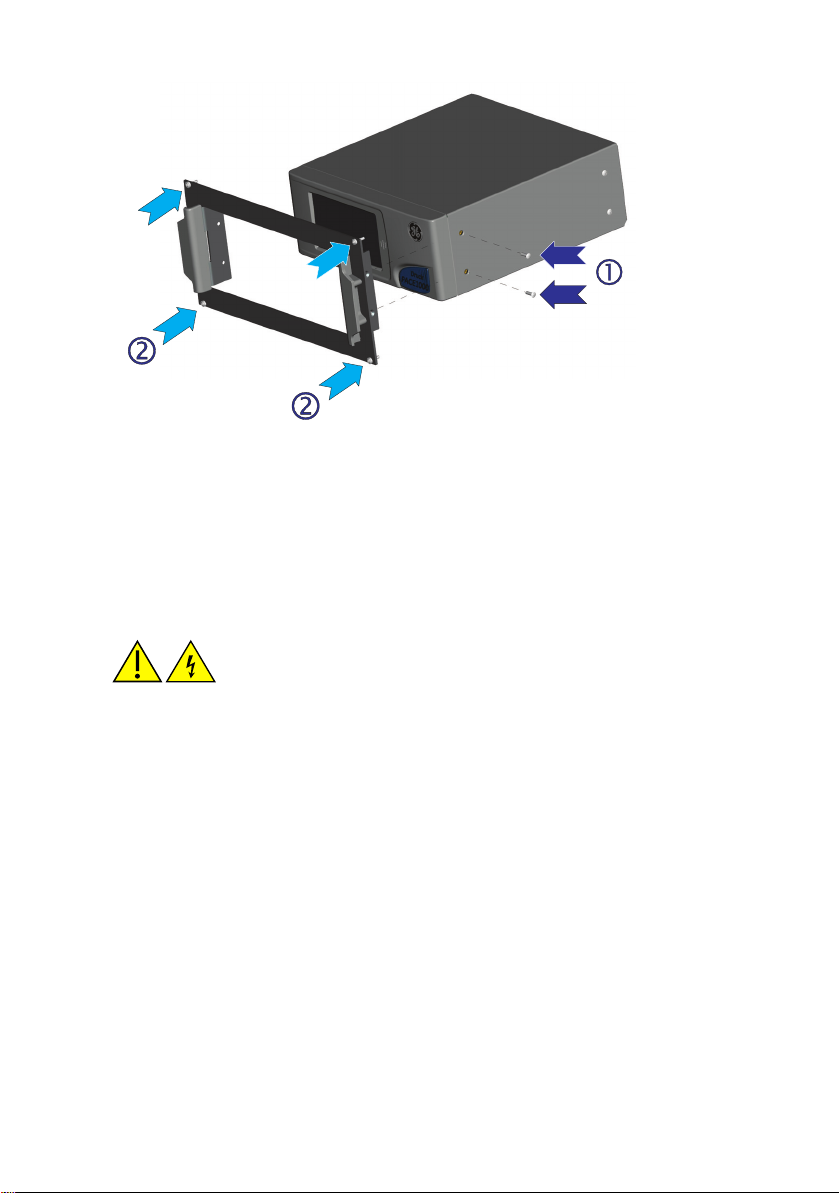
Figure 6 Panel-mounting
Procedure
1. Remove the four screws (1) from the instrument.
2. Locate the instrument in panel mount assembly.
3. Secure with the four screws (1).
4. Support the instrument and connect the cables and pipes.
5. Refer to the electrical connections below before fitting the instrument into the panel.
6. Secure the instrument in the panel with four screws and washers (2).
5 Electrical connections
WARNING
THE GROUND LEAD OF THE INSTRUMENT MUST BE CONNECTED TO THE AC SUPPLY
PROTECTIVE SAFETY GROUND.
ISOLATE THE POWER SUPPLY BEFORE MAKING ANY ELECTRICAL CONNECTIONS TO
THE REAR PANEL.
CAUTIONS
Use the power adaptor supplied with the instrument (GE part no. 191-370). Using
other power adaptors may cause over-heating, this can result in a fire.
Do not let the power adaptor come into contact with any moisture or liquids.
K0467 Revision A 11 [EN] English
Page 13
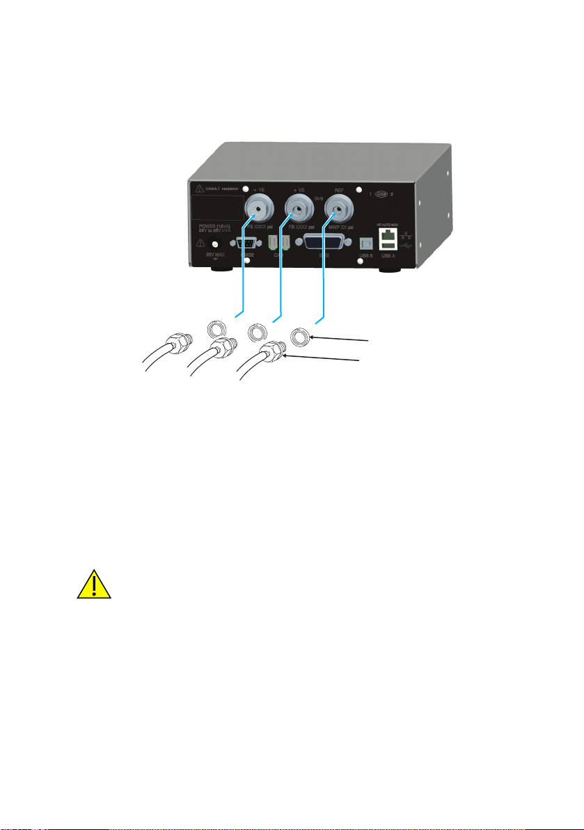
5.1 Connecting (Figure 7)
1. Before use, make sure the SELV power adaptor supplied with the
instrument is used (GE part number 191-370).
2. Install an accessible power isolator to use as the disconnecting device
in the power adaptor supply circuit.
3. The power adaptor input power supply range: 100 - 240VAC, 50 to
60Hz 660mA, Installation Category II.
Note: The power adaptor must be supplied by a fused or overload-protected
power supply.
4. Connect the power adaptor to the instrument.
5. Switch the power supply on.
6. Check that the front panel display shows the power-up sequence (Ref:
K0470, User manual, section 3.2).
Note:. After the power-up sequence, the instrument shows the default display on
the touch screen. The touch screen divides into a number of mimic keys.
5.2 Requirements for rack-mounted and panel-mounted instruments
1. Install an accessible power isolator to use as the disconnecting device
in the power adaptor supply circuit.
2. Set the power supply isolator to OFF.
3. Connect the power adaptor before sliding the instrument into the rack.
4. Set the power supply isolator to ON.
5. Check that the front panel display shows the power-up sequence (Ref: K0470, User manual, section 3.2).
6 Communication Connections
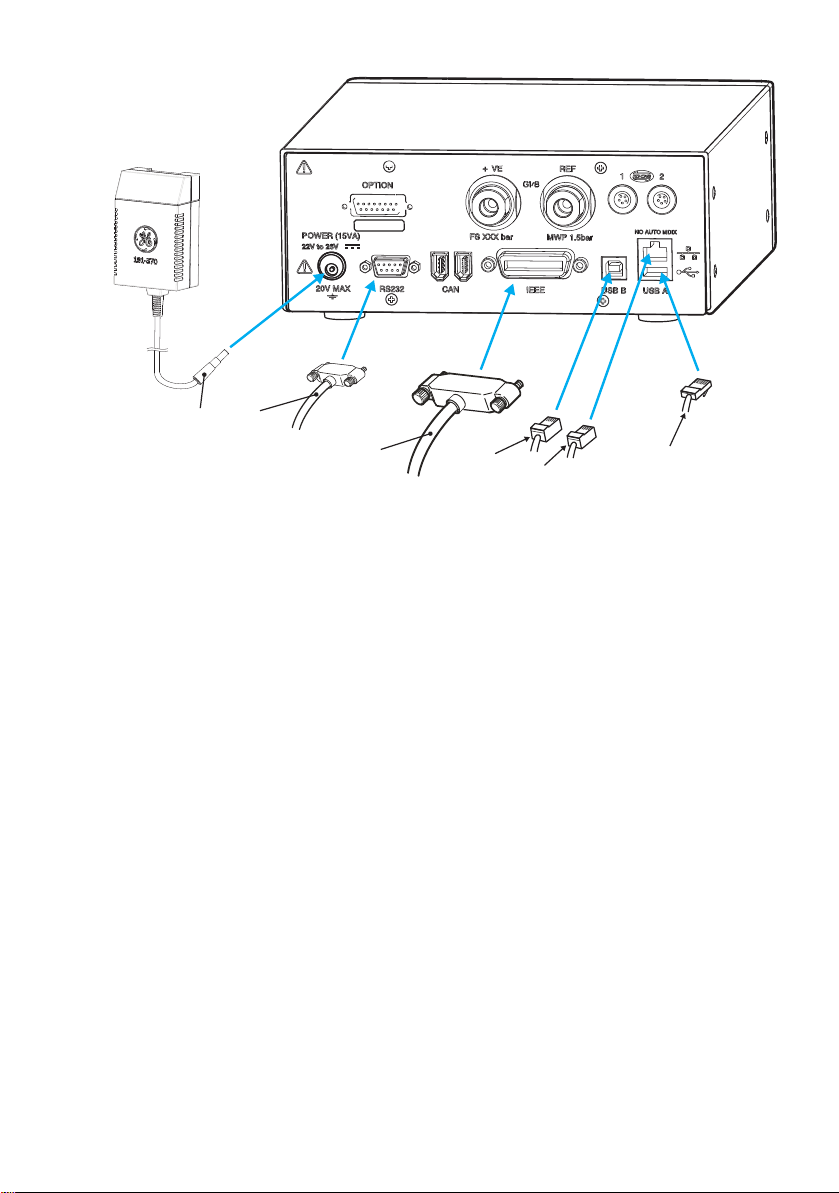
Connect the applicable connectors into the rear panel communications ports and, if appropriate,
secure with the captive screws.
Note: The RS232 and IEEE 488 interfaces are both enabled at power-up. Set the required
parameters in Supervisor Setup/communications menu, ((Ref: K0470, User manual, section
3.6).
[EN] English 12 K0467 Revision A
Page 14
2
4
5
6
7
22V to 26V
ANALOGUE 1
CONSULTHANDBOOK
1
Figure 7 Communication Connectors
1 Power supply adaptor 2 RS232 4 IEEE488
5 USB B 6 USB A 7 Ethernet (option)
6.1 RS232 Interface
When using the RS232 interface, a cable must be connected directly from the instrument to a
suitable port on the computer in a ‘point to point’ link.
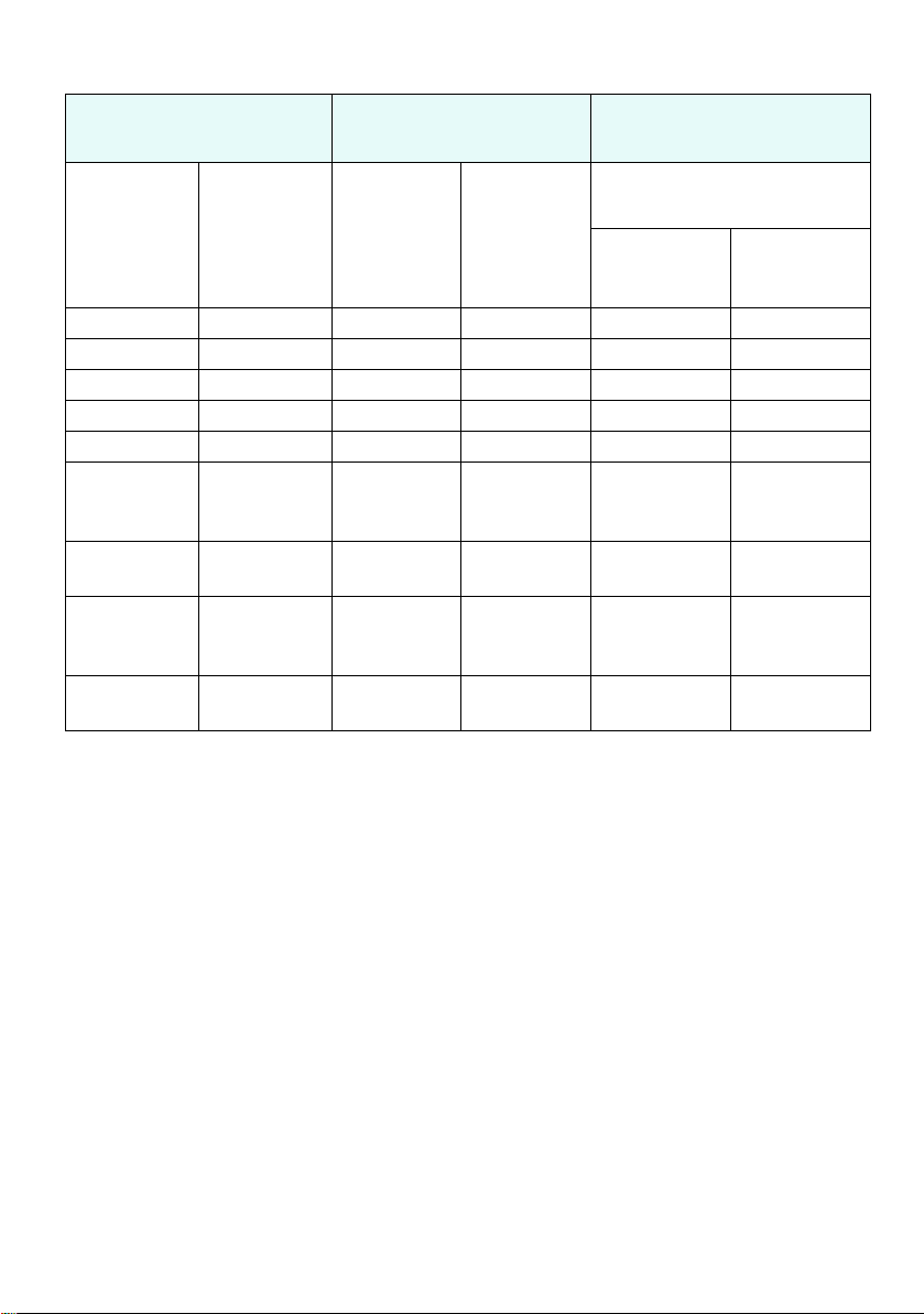
The pin connections for the 9-pin D-type, RS232 connector and the relationship between the
instrument and the RS232 control signals, together with device interconnection interface is shown
in Table 1. The instrument is configured as Data Circuit Terminating Equipment (DCE).
K0467 Revision A 13 [EN] English
Page 15
Instrument Control Line Computer/Printer
Instrument
Function
RxD (I/P) 3 TxD 3 2
TxD (O/P) 2 RxD 2 3
GND 5 GND 5 7
CTS (I/P) 7 RTS 7 4
RTS (O/P) 8 CTS 8 5
Pulled
high
internally
Not
connected
Pulled
high
internally
Equipment
chassis
Connector
9-way
D-type
Pin No.
1
4 DTR 4 20
6
Connector
shell
Signal
Direction
Cable Screen - 1
RS232
Terminology
RLSD
(DCD)
DSR
DCE Ready
Connector Type
9-way
D-type
Pin No.
18
66
25-way
D-type
Pin No.
Table 1 RS232 Connections
6.2 Handshaking connections
Software handshaking use: TXD, RXD and GND.
Hardware handshaking use: TXD, RXD, GND, CTS, RTS and DTR.
6.3 IEEE 488 Interface
The interface complies with IEEE 488 standard.
The IEEE 488 parallel interface connects a computer/controller to one or more PACE1000
instruments and other instruments.
Up to 30 instruments can be connected through a high-speed data bus to the computer/
controller.
Note: The length of each IEEE 488 cable must be less than 3 metres to comply with the EMC
requirements (Ref: Data sheet).
6.4 Single Unit Installation (Figure 8)
1. Connect an IEEE 488 connector/cable assembly to the rear panel of the instrument.
2. Connect the other end of the connector/cable assembly to the IEEE 488 connector on
the controller/computer.
3. Change the IEEE 488 communication parameters (Ref: K0470, User manual, Supervisor
set-up, section 6.7).
[EN] English 14 K0467 Revision A
Page 16
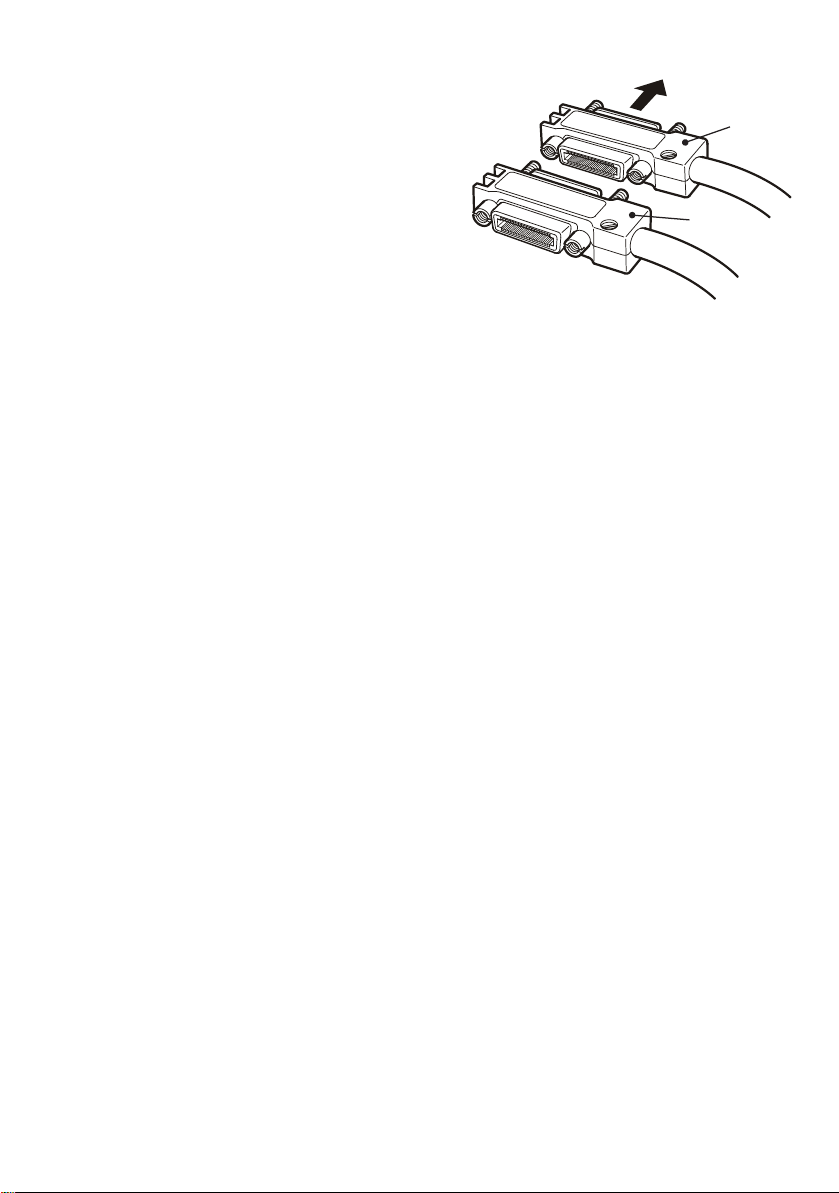
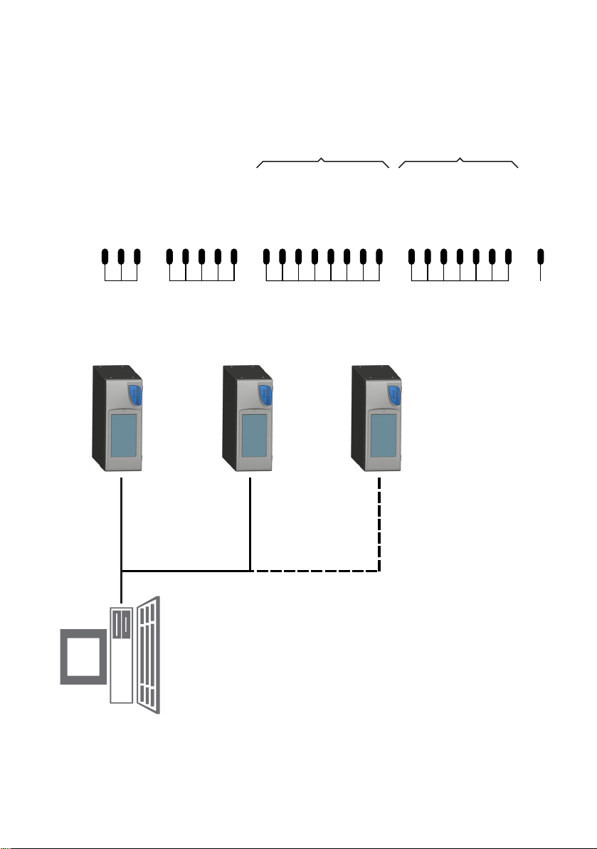
6.5 Multiple Unit Installation (Figure 8)
1
2
3
To install multiple units use stacking plugs to link the
first instrument and second instrument as follows::
1. Connector to rear panel of first instrument
(Ref Illustration).
2. Connector from controller/computer (Ref
Illustration).
3. Connector to rear panel of second
instrument (Ref Illustration).
4. Connect the IEEE 488 connector on the
controller/computer and the other
connector into the next instrument.
5. Repeat this procedure for all the instruments in the system.
Use the Supervisor set-up (communications) menu on each instrument to set-up the required
communication parameters (Ref: K0470, User manual 6.7).
K0467 Revision A 15 [EN] English
Page 17
IEEE 488
ADDRESS 1
ADDRESS 2
ADDRESS N
(30 maximum)
678
DAV (DATA VALID)
NRFD (NOT READY FOR DATA)
NDAC (NO DATA ACCEPTED)
59101117
EOI (END OF IDENTIFY)
IFC (INTERFACE CLEAR)
SRQ (SERVICE REQUEST)
ATN (ATTENTION)
REN (REMOTE ENABLE)
123413
DIO1
DIO2
DIO3
DIO4
DIO5
141516
DIO6
DIO7
DIO8
1819202122
GND (6)
GND (7)
GND (8)
GND (9)
GND (10)
23
24
GND (11)
GND
12 CHASSIS/FRAMECHASSIS/FRAME
DATA /
STATUS
BAR
0V (GND)
Figure 8 IEEE 488 Connection
[EN] English 16 K0467 Revision A
Page 18

7 Return Goods/Material Procedure
If the unit requires calibration or is unserviceable return it to the nearest GE Service Centre listed
at: www.gemeasurement.com
Contact the Service Department to obtain a Return Authorisation (Worldwide excluding USA).
In the USA obtain a Return Material Authorization [RMA].
Providing the following information on either a RGA or RMA:
• Product (i.e. PACE1000)
• Serial number
• Details of defect/work to be undertaken
• Calibration traceability requirements
• Operating conditions
Safety Precautions
You must inform GE if the product has been in contact with any hazardous or toxic
substance.
The relevant COSHH or in the USA, MSDS, references and precautions to be taken when
handling.
Important notice
Service or calibration by unauthorized sources will affect the warranty and may not
guarantee further performance.
8 Approved Service Agents For the list of service centres: www.gemeasurement.com
K0467 Revision A 17 [EN] English
Page 19
GE
Digital Solutions
Équipement d’étalonnage de pression automatisé
Consignes de sécurité et guide d’utilisation - K0467 Révision A
Indicateurs de pression PACE
© 2010 General Electric Company. Tous droits réservés. Spécifications sujettes à modifications
sans préavis. GE est une marque déposée de General Electric Company. Les autres noms de
société ou de produit mentionnés dans ce document peuvent être des marques commerciales ou
des marques déposées de leur détenteur respectif, non affilié à GE.
Page 20
5
6
3
4
A
B
C
7
22V to 26V
22V to 26V
XXXX
XXXX
XX
ANALOGUE 1
CONSULTHANDBOOK
CONSULTHANDBOOK
22V to 26V
ANALOGUE 1
CONSULTHANDBOOK
D
22V to 26V
ANALOGUE 1
VFC 1
15
CONSULTHANDBOOK
2
1
Figure 1
A Instrument à un orifice B Instrument à deux orifices C Instrument à trois orifices
D Capteur distant
1 Connecteur d’alimentation 2 Caractéristique électrique 3 Orifice de pression
4Orifice de pression 5
Pression de service
maximum
Pleine échelle de pression
6
(plage)
K0467 Révision A 1 [FR] Français
Page 21
7 Adaptateur électrique (voir liste d’emballage)
1 Introduction
L’indicateur de pression PACE mesure à la fois la pression pneumatique et la pression hydraulique,
et affiche sur un écran tactile en couleur la pression mesurée, ainsi que l’état de l’instrument. Cet
écran tactile permet d’effectuer des sélections et des réglages en mode de mesure. Cet
instrument peut être contrôlé à distance, à l’aide d’interfaces de communication.
1.1 Sécurité
Le fabricant a conçu cet appareil pour qu’il fonctionne en toute sécurité dans le cadre d’une
utilisation conforme aux procédures détaillées dans ce manuel. N’utilisez pas cet appareil à des fins
autres que celles spécifiées, sous peine de diminuer l’effet des dispositifs de protection internes.
Ce document contient des consignes d’utilisation et de sécurité à respecter impérativement pour
conserver l’appareil en bon état et garantir son fonctionnement en toute sécurité. Les consignes
de sécurité sont des mises en garde ou des avertissements destinés à prémunir l’utilisateur contre
les risques de blessure et à protéger l’appareil des dommages éventuels.
Faites appel à des techniciens qualifiés* et respectez les bonnes pratiques dans toutes les
procédures décrites dans ce document.
1.2 Pression
N’appliquez pas de pression supérieure à la pression de service maximum pour cet appareil.
1.3 Matériaux toxiques
Aucun matériau toxique n’entre dans la fabrication de cet appareil.
1.4 Entretien
L’appareil doit être entretenu conformément aux procédures détaillées dans ce document. Les
autres procédures du fabricant doivent être effectuées par un centre de réparation agréé ou le
centre de service du fabricant.
1.5 Question technique
Contactez le fabricant pour toute question technique.
*Un technicien qualifié doit posséder les connaissances techniques, la documentation, le matériel
de test et les outils spéciaux nécessaires pour effectuer les interventions requises sur cet appareil.
1.6 Spécifications générales
Affichage LCD : écran couleur tactile
Température de
fonctionnement
Température en stockage -20 °C à 70 °C (-4° à 158 °F)
Protection étanche IP20 (EN60529)
Humidité de fonctionnement 5 à 95 % d’humidité relative (sans condensation)
Vibrations MIL-PRF-28800 type 2 classe 5 style E/F
Altitude d’utilisation 2 000 mètres maximum (6 560 pieds)
CEM EN61326
Sécurité électrique EN 61010-1, UL61010-1, CSA 22.2, n° 61010-1 et CEI 61010-1
Adaptateur électrique Plage d’entrée : 100 à 240 V CA, 50 à 60 Hz, 660 mA.
Sécurité des pressions Directive sur les appareils sous pression – classe : bonnes
Degré de pollution 2
10 °C à 50 °C (50° à 122 °F)
Catégorie d’installation II
pratiques d’ingénierie (SEP) pour les fluides de groupe 2.
[FR] Français 2 K0467 Révision A
Page 22
Environnement d’utilisation Utilisation en intérieur uniquement. Non classé pour une
utilisation en atmosphères explosibles.
1.7 Symboles
Cet appareil satisfait aux exigences de toutes les directives européennes de
sécurité en vigueur. Cet appareil porte le marquage CE.
Ce symbole, sur l’appareil, signifie que l’utilisateur doit consulter le manuel
d’utilisation.
This symbol, on the equipment, indicates a warning and that the user should
refer to the user manual.
Ce symbole, sur l’instrument, indique que l’utilisateur doit consulter le
manuel d’utilisation. Ce symbole, dans le manuel, indique une situation
dangereuse.
This symbol warns the user of the danger of electric shock.
Ce symbole alerte l’utilisateur sur le danger de choc électrique.
Ne jetez pas ce produit avec les ordures ménagères. Faites appel à un
organisme agréé de collecte et/ou de recyclage des déchets électriques et
électroniques. Pour en savoir plus, contactez :
- notre service client : www.gemeasurement.com
- votre collectivité locale.
AVERTISSEMENTS
DÉBRANCHEZ LA OU LES SOURCES DE PRESSION ET ÉVACUEZ AVEC PRÉCAUTION LA
PRESSION DES CONDUITES DE PRESSION AVANT DE LES CONNECTER OU DE LES
DÉCONNECTER. PROCÉDEZ AVEC PRÉCAUTION.
UTILISEZ CET INSTRUMENT À LA PRESSION NOMINALE REQUISE UNIQUEMENT.
AVANT D’APPLIQUER UNE PRESSION, VÉRIFIEZ QU’AUCUN RACCORD OU
ÉQUIPEMENT N’EST ENDOMMAGÉ. REMPLACEZ TOUS LES RACCORDS ET
ÉQUIPEMENTS ENDOMMAGÉS. N’UTILISEZ AUCUN RACCORD OU ÉQUIPEMENT
ENDOMMAGÉ.
NE DÉPASSEZ PAS LA PRESSION DE SERVICE MAXIMALE DE L’INSTRUMENT.
CET APPAREIL N’EST PAS DESTINÉ À ÊTRE UTILISÉ AVEC DE L’OXYGÈNE.
K0467 Révision A 3 [FR] Français
Page 23

LE FIL DE MISE À LA TERRE DE L’INSTRUMENT DOIT ÊTRE CONNECTÉ À LA MISE À LA
TERRE DE SÉCURITÉ DE L’ALIMENTATION CA.
ISOLEZ L’ALIMENTATION ÉLECTRIQUE AVANT DE RÉALISER TOUT RACCORDEMENT
ÉLECTRIQUE SUR LE PANNEAU ARRIÈRE.
[FR] Français 4 K0467 Révision A
Page 24
1.8 Emballage
Vérifiez le contenu de l’emballage du PACE1000 par rapport à la liste suivante :
Liste d’emballage - PACE1000
i) Indicateur de pression PACE1000
ii) Adaptateur électrique (référence GE 191-370).
iii) Guide d’utilisation, consignes de sécurité et CD contenant l’ensemble de la
documentation.
iv) Certificat d’étalonnage.
1.9 Emballage en cas de stockage ou de transport
Pour stocker l’instrument ou le retourner à des fins d’étalonnage/de réparation, procédez
comme suit :
1. Emballez l’instrument (cf. K0470 Manuel d’utilisation, Références et spécifications,
section 6.13).
2. Retournez l’instrument pour étalonnage/réparation en suivant la procédure de retour de
matériel (cf. K0470 Manuel d’utilisation, Références et spécifications, section 6.12).
2 Préparation avant utilisation
L’instrument peut être :
• posé librement sur une surface horizontale ;
• monté sur panneau à l’aide du kit de montage sur panneau en option (cf. K0470 Manuel
d’utilisation, section 2.5) ;
• monté sur un rack standard de 19 pouces à l’aide du kit de montage en rack en option
(cf. K0470 Manuel d’utilisation, section 2.5).
Pour les instruments posés librement, les pieds à l’avant de la base peuvent être utilisés pour
surélever l’instrument de manière à avoir un meilleur angle de vision.
Remarque : L’air doit circuler librement autour de l’instrument, en particulier en cas de température
ambiante élevée.
2.1 Connexion de l’instrument
AVERTISSEMENTS
DÉBRANCHEZ LA OU LES SOURCES DE PRESSION ET ÉVACUEZ AVEC PRÉCAUTION LA
PRESSION DES CONDUITES DE PRESSION AVANT DE LES CONNECTER OU DE LES
DÉCONNECTER. PROCÉDEZ AVEC PRÉCAUTION.
UTILISEZ CET INSTRUMENT À LA PRESSION NOMINALE REQUISE UNIQUEMENT.
AVANT D’APPLIQUER UNE PRESSION, VÉRIFIEZ QU’AUCUN RACCORD OU
ÉQUIPEMENT N’EST ENDOMMAGÉ. REMPLACEZ TOUS LES RACCORDS ET
ÉQUIPEMENTS ENDOMMAGÉS. N’UTILISEZ AUCUN RACCORD OU ÉQUIPEMENT
ENDOMMAGÉ.
NE DÉPASSEZ PAS LA PRESSION DE SERVICE MAXIMALE DE L’INSTRUMENT.
CET APPAREIL N’EST PAS DESTINÉ À ÊTRE UTILISÉ AVEC DE L’OXYGÈNE.
K0467 Révision A 5 [FR] Français
Page 25
2.2 Pression pneumatique (Figure 2)
ISO 228 G1/8 ISO 228 G1/8
joint collé joint collé
Méthode recommandée Autre méthode au-dessous de 100 bar
Le filetage parallèle est obligatoire.
Le filetage femelle est un filetage
parallèle selon la norme ISO228/1
(DIN ISO228/1, JIS B0202) G1/8.
Le filetage conique n’est PAS autorisé.
Orifice de pression PACE
Panneau
arrière
PACE
9
8
Panneau
arrière
PACE
Orifice de pression PACE
1. Reportez-vous à la fiche technique pour connaître les milieux de pression corrects à
utiliser.
2. Raccordez l’appareil à tester (UUT) à l’orifice approprié.
Remarque : Pour les instruments équipés de raccords NPT, utilisez des joints collés appropriés,
comme indiqué sur la figure ci-dessous.
Figure 2 Raccords pneumatiques étanches
2.3 Raccords pneumatiques
AVERTISSEMENTS
LE FILETAGE PARALLÈLE EST OBLIGATOIRE. LE FILETAGE FEMELLE EST UN FILETAGE
PARALLÈLE SELON LA NORME ISO228/1 (DIN ISO228/1, JIS B0202) G1/8.
LE FILETAGE CONIQUE N’EST PAS AUTORISÉ.
Raccord
Entrée Filetage parallèle ISO228/1 G 1/8 (DIN ISO228/1, JIS B0202)
Référence Filetage parallèle ISO228/1 G 1/8 (DIN ISO228/1, JIS B0202)
Pour des exemples d’adaptateurs (cf. page 8).
[FR] Français 6 K0467 Révision A
Page 26
2.4 Pression d’entrée (Figure 3)
2
1
1) Connecteur 2) Joint collé
1. Assurez-vous que les systèmes de l’utilisateur peuvent être isolés et mis à l’air libre.
2. Connectez l’appareil à tester à l’orifice de sortie approprié.
Remarque : Pour les instruments équipés de raccords NPT, utilisez des joints collés appropriés (2),
comme indiqué sur la figure ci-dessous.
Figure 3 Raccords pneumatiques
3 Installation
L’instrument se raccorde à l’appareil à tester.
3.1 Pression d’entrée et équipement
La pression ne doit pas dépasser 1,25 fois la pleine échelle ou la pression de service maximum
indiquée sur le panneau arrière de l’instrument.
Pour protéger l’instrument contre les surpressions, un dispositif de protection approprié (comme
une soupape de surpression ou un disque de rupture) doit être installé afin d’éviter une
pressurisation excessive.
3.2 Raccord pneumatique
AVERTISSEMENT
LES PLAGES DE PRESSIONS SUPÉRIEURES À >210 BAR (3 000 PSI) SONT CONÇUES
POUR UN USAGE HYDRAULIQUE UNIQUEMENT.
MISES EN GARDE
Ne dépassez pas les pressions maximales indiquées dans le manuel des
composants (Component Manual) pour l’unité soumise à l’essai.
Réduisez la pression à une valeur contrôlée lorsque vous procédez à une
évacuation dans l’atmosphère.
Dépressurisez avec précaution tous les tuyaux à la pression atmosphérique avant
de les débrancher et de les brancher à l’appareil à tester.
K0467 Révision A 7 [FR] Français
Page 27
3.3 Raccordements
ISO 228 G1/8 ISO 228 G1/8
joint collé joint collé
Méthode recommandée Autre méthode au-dessous de 100 bar
IO-SNUBBER-1
IO-ADAPT-9/16AUTOC
ISO 228 mâle - 9/16 à autoclave
IO-DIFFUSER-1
IO-ADAPT-G1/4
ISO 228 mâle - G1/4 femelle
IO-ADAPT-1/8NPT
ISO 228 mâle - 1/8 NPT femelle
IO-ADAPT-1/4NPT
ISO 228 mâle - 1/4 NPT femelle
IO-ADAPT-7/16UNF
ISO 228 mâle - 7/16 UNF femelle
IO-ADAPT-AN4
ISO 228 mâle - AN4 37° mâle
IO-ADAPT-AN6
ISO 228 mâle – AN6 37° mâle
IO-ADAPT-BARB
ISO 228 mâle - 1/4 flexible
1. Coupez l’alimentation avant de connecter ou de déconnecter l’instrument.
2. Utilisez une méthode d’étanchéité appropriée pour tous les raccords de pression.
Remarque : Pour les instruments équipés de raccords NPT, utilisez des joints collés appropriés,
comme indiqué sur la figure ci-dessous.
3.4 Méthode de raccordement
3.5 Adaptateurs
Reportez-vous à la fiche technique pour découvrir la gamme d’adaptateurs.
[FR] Français 8 K0467 Révision A
Page 28

3.6 Pression hydraulique
AVERTISSEMENTS
LES FLUIDES HYDRAULIQUES SONT DES SUBSTANCES DANGEREUSES. RESPECTEZ
LES CONSIGNES DE SANTÉ ET DE SÉCURITÉ APPLICABLES. UTILISEZ DES BARRIÈRES
DE SÉCURITÉ ET DES LUNETTES DE PROTECTION APPROPRIÉES.
AVANT LA MISE SOUS PRESSION, VÉRIFIEZ QU’AUCUN RACCORD OU ÉQUIPEMENT
N’EST ENDOMMAGÉ ET VEILLEZ À CE QUE LE TAUX DE PRESSION DE L’ÉQUIPEMENT
SOIT CORRECT.
NE DÉPASSEZ PAS LA PRESSION DE SERVICE MAXIMALE DE L’INSTRUMENT.
PURGEZ TOUT L’AIR DU FLUIDE HYDRAULIQUE.
LES PLAGES DE PRESSIONS SUPÉRIEURES À >210 BAR (3 000 PSI) SONT CONÇUES
POUR UN USAGE HYDRAULIQUE UNIQUEMENT.
N’UTILISEZ PAS UN CAPTEUR POUR LE GAZ QUI A DÉJÀ ÉTÉ UTILISÉ AVEC UN FLUIDE
HYDRAULIQUE.
MISES EN GARDE
Ne dépassez pas les pressions maximales indiquées dans le manuel des
composants de l’appareil à tester.
Réduisez la pression à une valeur contrôlée lorsque vous procédez à une
évacuation dans l’atmosphère.
Dépressurisez avec précaution tous les tuyaux à la pression atmosphérique avant
de les débrancher et de les brancher à l’appareil à tester.
Suivez les règles de propreté absolue quand vous utilisez l’appareil.
L’appareil risque d’être sérieusement endommagé si l’équipement qui lui est
raccordé est contaminé.
Ne raccordez à l’appareil que du matériel propre.
Un filtre extérieur est recommandé pour éviter tout risque de contamination.
3.7 Installation
L’instrument se raccorde à l’appareil à tester.
3.8 Pression d’entrée et équipement
1. La pression ne doit pas dépasser 1,25 fois la pleine échelle ou la pression de service
maximum indiquée sur le panneau arrière de l’instrument.
2. Pour protéger l’instrument contre les surpressions, un dispositif de protection approprié
(comme une soupape de surpression ou un disque de rupture) doit être installé afin de
limiter la pression à une valeur inférieure à la pression de service maximum.
Remarque : Pour les instruments équipés de raccords NPT, utilisez des joints collés appropriés,
comme indiqué sur la figure ci-dessous.
K0467 Révision A 9 [FR] Français
Page 29
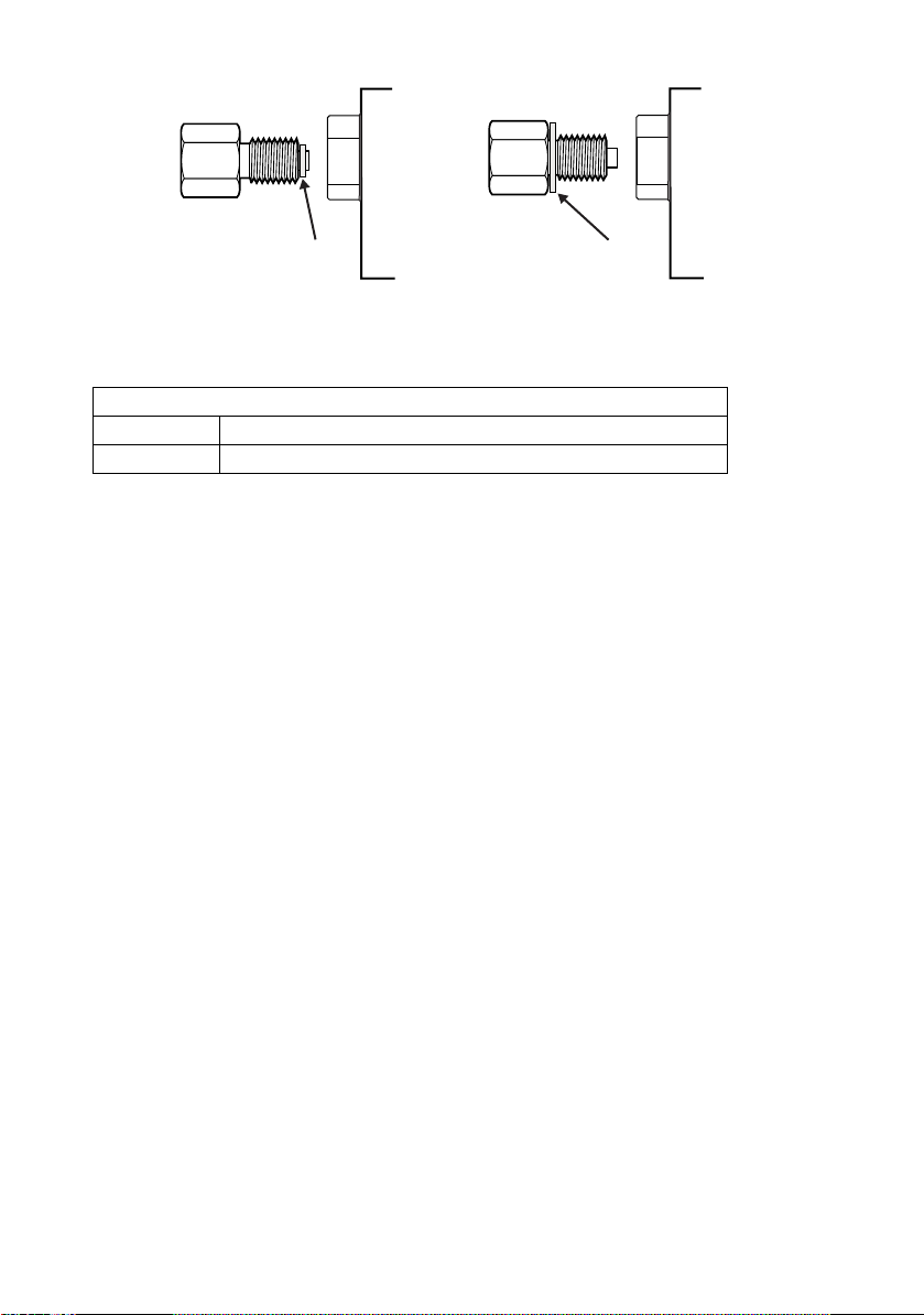
Figure 4 Raccords hydrauliques étanches
ISO 228 G1/8 ISO 228 G1/8
joint collé joint collé
Méthode recommandée Autre méthode au-dessous de 100 bar
3.9 Raccords hydrauliques Raccord
Entrée Filetage parallèle ISO228/1 G 1/8 (DIN ISO228/1, JIS B0202)
Référence Filetage parallèle ISO228/1 G 1/8 (DIN ISO228/1, JIS B0202)
Remarque : Les raccords de pression supérieurs à 210 bar sont des raccords mâles 18UNF 9/16” à
autoclave.
1. Coupez l’alimentation avant de connecter ou de déconnecter l’instrument.
2. Utilisez une méthode d’étanchéité appropriée pour tous les raccords de pression.
3. Isolez les pressions hydrauliques et dépressurisez les tuyaux avant de connecter ou de
déconnecter l’instrument.
3.10 Entrée de pression (Figure 2)
1. Assurez-vous que les systèmes de l’utilisateur peuvent être isolés et mis à l’air libre.
2. Utilisez une méthode d’étanchéité appropriée pour tous les raccords de pression.
3. Le fluide hydraulique doit être propre. Reportez-vous aux spécifications indiquées dans
la fiche technique.
4. Raccordez l’appareil à tester à l’orifice approprié.
5. Remplissez et purgez l’appareil à tester et les tuyaux de raccordement.
4 Kits de montage
4.1 Option de montage en rack (Figure 5)
Un espace suffisant doit être disponible à l’arrière de l’instrument pour l’ensemble des câbles et
des tuyaux. La longueur des câbles et des tuyaux doit être suffisante pour permettre de retirer et
d’installer l’instrument. L’orifice de ventilation de l’instrument ne doit pas être obstrué. L’air doit
circuler librement dans le rack et autour de l’instrument, en particulier en cas de température
ambiante élevée.
[FR] Français 10 K0467 Révision A
Page 30
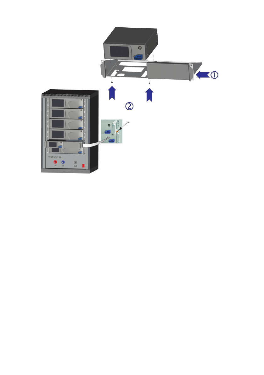
Figure 5 Montage en rack
Procédure
1. Placez l’instrument dans l’ensemble de montage en rack (1).
2. Fixez-le avec les quatre vis M3 x 6 (2) (longueur maximale M3 x 8).
3. Tout en tenant l’instrument, connectez les câbles et les tuyaux.
4. Reportez-vous à la section sur les raccordements électriques ci-dessous avant de
procéder à l’installation de l’instrument dans le rack.
5. Placez temporairement les deux ergots* de chaque côté du rack.
6. Positionnez l’instrument et faites-le glisser dans le rack.
7. Positionnez l’instrument sur les ergots*.
8. Fixez l’instrument à l’intérieur du rack à l’aide des deux vis et rondelles (fournies).
9. Retirez les deux ergots* et remplacez-les par les deux vis et rondelles restantes
(fournies).
4.2 Option de montage sur panneau (Figure 6)
Un espace suffisant doit être disponible à l’arrière de l’instrument pour l’ensemble des câbles et
des tuyaux.
La longueur des câbles et des tuyaux doit être suffisante pour permettre de retirer et d’installer
l’instrument.
L’orifice de ventilation de l’instrument ne doit pas être obstrué.
L’air doit circuler librement dans le rack et autour de l’instrument, en particulier en cas de
température ambiante élevée.
K0467 Révision A 11 [FR] Français
Page 31

Figure 6 Montage sur panneau
Procédure
1. Retirez les quatre vis (1) de l’instrument.
2. Placez l’instrument dans l’ensemble de montage sur panneau.
3. Fixez-le avec les quatre vis (1).
4. Tout en tenant l’instrument, connectez les câbles et les tuyaux.
5. Reportez-vous à la section sur les raccordements électriques ci-dessous avant de
procéder à l’installation de l’instrument sur le panneau.
6. Fixez l’instrument sur le panneau à l’aide des quatre vis et rondelles (2).
5 Raccordements électriques
AVERTISSEMENT
LE FIL DE MISE À LA TERRE DE L’INSTRUMENT DOIT ÊTRE CONNECTÉ À LA MISE À LA
TERRE DE SÉCURITÉ DE L’ALIMENTATION CA.
ISOLEZ L’ALIMENTATION ÉLECTRIQUE AVANT DE RÉALISER TOUT RACCORDEMENT
ÉLECTRIQUE SUR LE PANNEAU ARRIÈRE.
MISES EN GARDE
Utilisez l’adaptateur électrique fourni avec l’instrument (réf. GE 191-370).
L’utilisation de tout autre adaptateur électrique peut causer une surchauffe, qui
elle-même peut entraîner un incendie.
Évitez absolument tout contact de l’adaptateur électrique avec de l’humidité ou
des liquides.
[FR] Français 12 K0467 Révision A
Page 32

5.1 Raccordement (Figure 7)
1. Avant de faire fonctionner l’instrument, veillez à utiliser l’adaptateur
électrique TBTS fourni avec l’instrument (réf. GE 191-370).
2. Installez un interrupteur d’alimentation accessible qui servira de
dispositif sectionneur dans le circuit de l’adaptateur électrique.
3. Plage d’alimentation d’entrée de l’adaptateur électrique : 100 à
240 V CA, 50 à 60 Hz, 660 mA, catégorie d’installation II.
Remarque : L’adaptateur électrique doit être protégé par un dispositif à fusibles
ou de protection contre les surcharges.
4. Connectez l’adaptateur électrique à l’instrument.
5. Remettez la source d’alimentation électrique sous tension.
6. Vérifiez que l’écran en face avant affiche la séquence de mise sous
tension (cf. K0470 Manuel d’utilisation, section 3.2).
Remarque : Après cette séquence, l’instrument affiche l’écran par défaut sur
l’écran tactile. Ce dernier comporte différentes touches.
5.2 Conditions liées aux instruments montés en rack ou sur panneau
1. Installez un interrupteur d’alimentation accessible qui servira de
dispositif sectionneur dans le circuit de l’adaptateur électrique.
2. Placez l’interrupteur d’alimentation sur la position ARRÊT.
3. Connectez l’adaptateur électrique avant de faire glisser l’instrument dans le rack.
4. Placez l’interrupteur d’alimentation sur la position MARCHE.
5. Vérifiez que l’écran en face avant affiche la séquence de mise sous tension
(cf. K0470 Manuel d’utilisation, section 3.2).
6 Raccordements de communication
Insérez les connecteurs appropriés dans les ports de communication en face arrière, puis fixez-les
à l’aide des vis imperdables si nécessaire.
Remarque : Les interfaces RS232 et IEEE 488 s’activent toutes deux à la mise sous tension. Définissez
les paramètres requis dans le menu Supervisor Setup/communications (Configuration de
superviseur/communications) (cf. K0470 Manuel d’utilisation, section 3.6).
K0467 Révision A 13 [FR] Français
Page 33

2
4
5
6
7
22V to 26V
ANALOGUE 1
CONSULTHANDBOOK
1
Figure 7 Connecteurs de communication
1 Adaptateur électrique 2 RS232 4 IEEE488
5 USB B 6 USB A 7 Ethernet (option)
6.1 Interface RS232
Lorsque vous utilisez l’interface RS232, un câble doit être connecté directement de l’instrument à
un port approprié de l’ordinateur via une liaison point à point.
Le tableau 1-1 présente les connexions des broches du connecteur RS232 de type D à 9 broches
et la relation entre l’instrument et les signaux de contrôle RS232, ainsi que l’interface
d’interconnexion de périphérique. L’instrument est configuré comme un équipement ETCD
(équipement de terminaison de circuit de données).
[FR] Français 14 K0467 Révision A
Page 34

Instrument Ligne de contrôle Ordinateur/imprimante
Fonction de
l’instrument
RxD (I/P) 3 TxD 3 2
TxD (O/P) 2 RxD 2 3
GND (TERRE) 5 GND (TERRE) 5 7
CTS (I/P) 7 RTS 7 4
RTS (O/P) 8 CTS 8 5
Placé
en position
haute
en interne
Non connecté 4 DTR 4 20
Placé
en position
haute
en interne
Châssis de
l’équipement
Connecteur
9 voies
type D
No. de broche
1
6
Boîtier de
connecteur
Sens du
signal
Terminologie
RS232
RLSD
(DCD)
DSR
DCE prêt
Blindage de
câble
Type de connecteur
9 voies
type D
No. de broche
18
66
-1
25 voies
type D
No. de broche
Tableau 1 Connexions RS232
6.2 Connexions de synchronisation
Synchronisation logicielle : TXD, RXD et GND.
Synchronisation matérielle : TXD, RXD, GND, CTS, RTS et DTR.
6.3 Interface IEEE 488
L’interface est conforme à la norme IEEE 488.
L’interface parallèle IEEE 488 permet de connecter un ordinateur/un contrôleur à un ou plusieurs
indicateurs PACE1000 et à d’autres instruments.
Il est possible de connecter jusqu’à 30 instruments à un ordinateur/contrôleur par l’intermédiaire
d’un bus de données à haut débit.
Remarque : La longueur de chaque câble IEEE 488 doit être inférieure à 3 mètres afin de respecter
la norme CEM (cf. fiche technique).
6.4 Installation d’une unité (Figure 8)
1. Raccordez un connecteur/faisceau de câbles IEEE 488 au panneau arrière de l’instrument.
2. Raccordez l’autre extrémité du connecteur ou du faisceau de câbles au connecteur
IEEE 488 du contrôleur ou de l’ordinateur.
3. Modifiez les paramètres de communication IEEE 488 (cf. K0470 Manuel d’utilisation,
section 6.7 Configuration de superviseur).
K0467 Révision A 15 [FR] Français
Page 35

6.5 Installation de plusieurs unités (Figure 8)
1
2
3
Pour installer plusieurs unités, utilisez des fiches
multiprises afin de connecter le premier instrument
au second comme suit :
1. Connecteur au panneau arrière du premier
instrument (voir illustration).
2. Connecteur provenant du contrôleur/de
l’ordinateur (voir illustration).
3. Connecteur au panneau arrière du
deuxième instrument (voir illustration).
4. Raccordez le connecteur IEEE 488 du
contrôleur/de l’ordinateur et l’autre
connecteur dans l’instrument suivant.
5. Répétez cette procédure pour tous les instruments du système.
Utilisez le menu de configuration du superviseur (communications) de chaque instrument pour
configurer les paramètres de communication requis (cf. K0470 Manuel d’utilisation, section 6.7).
[FR] Français 16 K0467 Révision A
Page 36

IEEE 488
ADRESSE 1
ADRESSE 2
ADRESSE N
¬PD[LPXP
678
'$9'211e(69$/,'(6
15)'12135Ç73285'(6'211e(6
1'$&$8&81('211e($&&(37e(
59101117
(2,),1'·,'(17,),&$7,21
,)&())$&(5/,17(5)$&(
654'(0$1'('(6(59,&(
$71$77(17,21
5(1$&7,9$7,21',67$1&(
123413
DIO1
DIO2
DIO3
DIO4
DIO5
141516
DIO6
DIO7
DIO8
1819202122
*1'
*1'
*1'
*1'
*1'
23
24
*1'
GND
12 CHÂSSIS/CADRECHÂSSIS/CADRE
DONNÉES/
BARRE D'ÉTAT
¬9*1'
Figure 8 Connexion IEEE 488
K0467 Révision A 17 [FR] Français
Page 37

7 Procédure de retour de matériel
Si l’appareil doit être étalonné ou s’il est hors service, il peut être retourné au centre de réparation
GE le plus proche (voir www.gemeasurement.com).
Contactez le service de réparation pour un obtenir un numéro d’autorisation de retour de matériel
(monde entier à l’exclusion des États-Unis).
Aux États-Unis, procurez-vous une autorisation de retour de matériel [RMA].
Les informations suivantes doivent figurer sur l’autorisation RGA ou RMA :
• Produit (PACE1000)
• Numéro de série
• Précisions concernant le défaut/travail à effectuer
• Exigences de traçabilité de l’étalonnage
• Conditions de fonctionnement
Consignes de sécurité
Vous devez informer GE si le produit a été en contact avec une substance dangereuse
ou toxique.
Précisez les références COSHH, ou FDS pour les États-Unis, ainsi que les précautions à
prendre pour sa manipulation.
Remarque importante
Toute réparation ou tout étalonnage non autorisé annule la garantie et peut
compromettre les performances de l’appareil.
8 Centres de réparation agréés Pour obtenir la liste de nos centres de réparation : www.gemeasurement.com
[FR] Français 18 K0467 Révision A
Page 38

K0467 Révision A 19 [FR] Français
Page 39

GE
Digital Solutions
Gerät zur automatischen Druckkalibrierung
Sicherheitshinweise und Bedienungsanleitung – K0467 Revision A
PACE Druckanzeigen
© 2010 General Electric Company. Alle Rechte vorbehalten. Technische Angaben können ohne
Vorankündigung geändert werden. GE ist eine eingetragene Marke der General Electric Company.
Andere Unternehmen oder Produktnamen, die in diesem Dokument genannt werden, können Marken
oder eingetragene Marken der jeweiligen Unternehmen sein, die nicht mit GE verbunden sind.
Page 40

5
6
3
4
A
B
C
7
22V to 26V
22V to 26V
XXXX
XXXX
XX
ANALOGUE 1
CONSULTHANDBOOK
CONSULTHANDBOOK
22V to 26V
ANALOGUE 1
CONSULTHANDBOOK
D
22V to 26V
ANALOGUE 1
VFC 1
15
CONSULTHANDBOOK
2
1
Abbildung 1
A Gerät mit einem Anschluss B Gerät mit zwei Anschlüssen C Gerät mit drei Anschlüssen
D Gerät mit dezentralem Sensor
1 Netzanschluss 2 Elektrische Leistungsdaten 3 Druckanschluss
4 Druckanschluss 5 Maximaler Arbeitsdruck 6 Druckendwert (Bereich)
7 Netzadapter (siehe Packliste)
K0467 Revision A 1 [DE] Deutsch
Page 41

1 Einführung
Die PACE Druckanzeige misst und steuert hydraulische und pneumatische Drücke und zeigt auf
einem farbigen Touchscreen den gemessenen Druck sowie den Gerätestatus an. Über den
Touchscreen können in den Messmodi Optionen ausgewählt und Einstellungen festgelegt werden.
Das Gerät kann dezentral über Kommunikationsschnittstellen bedient werden.
1.1 Sicherheit
Der Hersteller hat dieses Gerät so konstruiert, dass sein Betrieb sicher ist, wenn es gemäß den in
diesem Handbuch beschriebenen Verfahren eingesetzt wird. Dieses Gerät darf nur für den in
diesem Handbuch angegebenen Zweck verwendet werden; andernfalls können die
Schutzfunktionen des Produkts beeinträchtigt werden.
Die Betriebsanweisungen und Sicherheitshinweise in diesem Handbuch müssen befolgt werden,
um einen sicheren Betrieb und sicheren Zustand des Geräts zu gewährleisten. Die
Sicherheitshinweise („Warnung“, „Achtung“) dienen dem Schutz des Anwenders und des Geräts
vor Verletzungen bzw. Beschädigungen.
Alle Verfahren in diesem Dokument sind von qualifizierten* Fachkräften unter Einhaltung
bewährter Methoden durchzuführen.
1.2 Druck
Wenden Sie keinen Druck auf das Gerät an, der den maximalen Arbeitsdruck übersteigt.
1.3 Giftige Stoffe
Bei der Herstellung des Geräts werden keine giftigen Stoffe verwendet.
1.4 Wartung
Die Wartung des Geräts muss entsprechend den in diesem Dokument angegebenen Verfahren
erfolgen. Weitere Herstelleranweisungen sollten durch autorisierte Servicevertretungen oder die
Kundendienstabteilung des Herstellers ausgeführt werden.
1.5 Technische Beratung
Bitte wenden Sie sich wegen technischer Beratung an den Hersteller.
*Für Arbeiten an diesem Gerät muss der qualifizierte Techniker über das notwendige technische
Fachwissen, die entsprechende Dokumentation sowie spezielle Testausrüstung und Werkzeuge
verfügen.
1.6 Allgemeine technische Daten
Anzeige LCD: Farbdisplay mit Touchscreen
Betriebstemperatur 10 °C bis 50 °C (50 °F bis 122 °F)
Lagertemperatur -20 °C bis 70 °C (-4 °F bis 158 °F)
Schutzart IP20 (EN 60529)
Feuchtigkeit (Betrieb) 5 bis 95 % relative Feuchtigkeit, nicht kondensierend
Vibrationen MIL-PRF-28800 Typ 2, Klasse 5, Typ E/F
Aufstellhöhe Maximal 2000 Meter
EMV EN 61326
Elektrische Sicherheit EN 61010-1, UL 61010-1, CSA 22.2, No. 61010-1 und IEC 61010-1
Netzteil Eingangsbereich: 100 bis 240 VAC, 50 bis 60 Hz, 660 mA, Einbaukategorie II
Drucktechnische
Sicherheit
Emissionsgrad 2
Betriebsumgebung Nur zur Verwendung im Innenbereich. Nicht für den Gebrauch in
Druckgeräterichtlinie, Klasse: Sound Engineering Practice (SEP) für
Flüssigkeiten der Stufe 2
explosionsgefährdeten Bereichen zugelassen.
[DE] Deutsch 2 K0467 Revision A
Page 42

1.7 Symbole
Dieses Gerät erfüllt die Anforderungen der entsprechenden europäischen
Sicherheitsrichtlinien. Das Gerät ist mit dem CE-Zeichen versehen.
Dieses Symbol auf dem Gerät gibt an, dass der Anwender in der Anleitung
nachschlagen sollte.
Dieses Symbol weist auf eine Warnung hin und gibt an, dass der Anwender in
der Anleitung nachschlagen sollte.
Ce symbole, sur l’instrument, indique que l’utilisateur doit consulter le manuel
d’utilisation. Ce symbole, dans le manuel, indique une situation dangereuse.
Dieses Symbol warnt den Anwender vor Stromschlaggefahr.
Ce symbole alerte l’utilisateur sur le danger de choc électrique.
Dieses Gerät darf nicht über den Hausmüll entsorgt werden. Geben Sie das
Gerät bei einer zugelassenen Stelle ab, die Elektro- und Elektronik-Altgeräte
sammelt und/oder wiederverwertet. Weitere Informationen erhalten Sie bei
folgenden Stellen:
- Unsere Kundendienstabteilung: www.gemeasurement.com
- Ihre lokale Behörde
WARNHINWEISE
SCHALTEN SIE VOR DEM ANSCHLIESSEN ODER TRENNEN DER DRUCKLEITUNGEN
DEN VERSORGUNGSDRUCK AB UND LASSEN SIE VORSICHTIG DEN DRUCK AUS DEN
LEITUNGEN AB. GEHEN SIE VORSICHTIG VOR.
VERWENDEN SIE NUR GERÄTE MIT DEM RICHTIGEN NENNDRUCK.
UNTERSUCHEN SIE ALLE ARMATUREN UND GERÄTE AUF BESCHÄDIGUNGEN, BEVOR
SIE DRUCK BEAUFSCHLAGEN. TAUSCHEN SIE ALLE BESCHÄDIGTEN ARMATUREN UND
GERÄTE AUS. VERWENDEN SIE KEINE BESCHÄDIGTEN ARMATUREN UND GERÄTE.
DER MAXIMALE ARBEITSDRUCK DES INSTRUMENTS DARF NICHT ÜBERSCHRITTEN
WERDEN.
DIESES GERÄT IST NICHT FÜR DEN EINSATZ MIT SAUERSTOFF ZUGELASSEN.
DER ERDLEITER DES GERÄTS MUSS AN DIE SCHUTZERDUNG DER
WECHSELSTROMVERSORGUNG ANGESCHLOSSEN WERDEN.
TRENNEN SIE DIE NETZVERSORGUNG, BEVOR SIE ELEKTRISCHE ANSCHLÜSSE AN DER
RÜCKWAND VORNEHMEN.
K0467 Revision A 3 [DE] Deutsch
Page 43

1.8 Verpackung
Prüfen Sie den Inhalt der PACE1000-Verpackung anhand der folgenden Liste:
Packliste – PACE1000
i) Druckanzeige PACE1000
ii) Adapter, Netzteil (GE-Bestellnr. 191-370)
iii) Bedienungsanleitung und Sicherheitshinweise sowie eine CD mit der vollständigen
Dokumentation
iv) Kalibrierzertifikat
1.9 Verpacken für die Lagerung oder den Transport
Wenn Sie das Gerät einlagern oder zur Kalibrierung bzw. Reparatur einschicken möchten, gehen
Sie folgendermaßen vor:
1. Verpacken Sie das Gerät (siehe K0470, Bedienungsanleitung, Abschnitt 6.13, „Referenz
und Spezifikation“).
2. Schicken Sie das Gerät zur Kalibrierung bzw. Reparatur gemäß dem
Rücksendeverfahren ein (siehe K0470, Bedienungsanleitung, Abschnitt 6.12, „Referenz
und Spezifikation“).
2 Vorbereitung zur Inbetriebnahme
Das Gerät kann folgendermaßen verwendet werden:
• Freistehend auf einer horizontalen Oberfläche
• In einer Tafel eingebaut mit dem optionalen Tafelmontagesatz (siehe K0470,
Bedienungsanleitung, Abschnitt 2.5)
• In ein 19-Zoll-Standardgestell eingebaut mit dem optionalen Gestellmontagesatz
(siehe K0470, Bedienungsanleitung, Abschnitt 2.5)
Bei freistehenden Geräten können Sie mithilfe der Vorderfüße an der Unterseite die Höhe des
Geräts verstellen, um einen günstigeren Sichtwinkel zu erhalten.
Hinweis: Sorgen Sie vor allem bei hohen Umgebungstemperaturen für eine ungehinderte
2.1 Anschließen des Geräts
Luftzirkulation um das Gerät herum.
WARNHINWEISE
SCHALTEN SIE VOR DEM ANSCHLIESSEN ODER TRENNEN DER DRUCKLEITUNGEN
DEN VERSORGUNGSDRUCK AB UND LASSEN SIE VORSICHTIG DEN DRUCK AUS DEN
LEITUNGEN AB. GEHEN SIE VORSICHTIG VOR.
VERWENDEN SIE NUR GERÄTE MIT DEM RICHTIGEN NENNDRUCK.
UNTERSUCHEN SIE ALLE ARMATUREN UND GERÄTE AUF BESCHÄDIGUNGEN, BEVOR
SIE DRUCK BEAUFSCHLAGEN. TAUSCHEN SIE ALLE BESCHÄDIGTEN ARMATUREN UND
GERÄTE AUS. VERWENDEN SIE KEINE BESCHÄDIGTEN ARMATUREN UND GERÄTE.
DER MAXIMALE ARBEITSDRUCK DES INSTRUMENTS DARF NICHT ÜBERSCHRITTEN
WERDEN.
DIESES GERÄT IST NICHT FÜR DEN EINSATZ MIT SAUERSTOFF ZUGELASSEN.
[DE] Deutsch 4 K0467 Revision A
Page 44

2.2 Pneumatischer Druck (Abbildung 2)
ISO 228 G1/8 ISO 228 G1/8
Verbunddichtung Verbunddichtung
Empfohlene Methode Alternative Methode unter 100 bar
Es müssen Parallelgewinde verwendet
werden.
Als Innengewinde sind Parallelgewinde
nach ISO 228/1 (DIN ISO228/1,
JIS B0202) G1/8 zu verwenden.
Kegelgewinde sind NICHT zulässig.
PACE Druckanschluss
PACE
Rückwand
9
8
PACE
Rückwand
PACE Druckanschluss
1. Hinweise zu den verwendbaren Druckmedien finden Sie im Datenblatt.
2. Schließen Sie den Prüfling an den entsprechenden Anschluss an.
Hinweis: Verwenden Sie für Geräte mit NPT-Anschlüssen Verbunddichtungen wie in der folgenden
Abbildung gezeigt.
Abbildung 2: Pneumatikanschlüsse mit Verbunddichtungen
2.3 Pneumatikanschlüsse
WARNHINWEISE
ES MÜSSEN PARALLELGEWINDE VERWENDET WERDEN. ALS INNENGEWINDE SIND
PARALLELGEWINDE NACH ISO 228/1 (DIN ISO228/1, JIS B0202) G1/8 ZU
VERWENDEN.
KEGELGEWINDE SIND NICHT ZULÄSSIG.
Anschluss
Eingang G 1/8 Parallelgewinde nach ISO 228/1 (DIN ISO228/1, JIS B0202)
Referenz G 1/8 Parallelgewinde nach ISO 228/1 (DIN ISO228/1, JIS B0202)
Beispiele für Adapter (siehe Seite 8).
K0467 Revision A 5 [DE] Deutsch
Page 45

2.4 Eingangsdruck (Abbildung 3)
2
1
1) Steckverbinder
2) Verbunddichtung
1. Vergewissern Sie sich, dass die Verbrauchersysteme isoliert und entlüftet werden können.
2. Schließen Sie den Prüfling (UUT) an den Ausgangsanschluss an.
Hinweis: Verwenden Sie für Geräte mit NPT-Anschlüssen Verbunddichtungen (2) wie in der
folgenden Abbildung gezeigt.
Abbildung 3: Pneumatikanschlüsse
3 Installation
Das Gerät wird an den Prüfling angeschlossen.
3.1 Eingangsdruck und Ausrüstung
Der Druck darf das 1,25-fache des Skalenendwerts bzw. den an der Rückwand des Geräts
angegebenen maximalen Arbeitsdruck nicht übersteigen.
Um das Gerät vor Überdruck zu schützen, muss eine geeignete Schutzvorrichtung (wie ein
Begrenzungsventil oder eine Berstscheibe) vorgesehen werden, die das Entstehen von Überdruck
verhindert.
3.2 Pneumatikanschluss
WARNUNG
DIE DRUCKBEREICHE >210 bar (3000 psi) SIND NUR FÜR HYDRAULIKDRÜCKE
ZUGELASSEN.
ACHTUNG
Überschreiten Sie nicht die für den Prüfling im Handbuch zur jeweiligen
Komponente angegebenen maximalen Druckwerte.
Senken Sie den Druck beim Ablassen in die Umgebung kontrolliert ab.
Bringen Sie vorsichtig alle Leitungen auf den Luftdruck, bevor Sie sie vom Prüfling
trennen oder daran anschließen.
[DE] Deutsch 6 K0467 Revision A
Page 46

3.3 Anschlüsse
ISO 228 G1/8 ISO 228 G1/8
Verbunddichtung Verbunddichtung
Empfohlene Methode Alternative Methode unter 100 bar
IO-SNUBBER-1
IO-ADAPT-9/16AUTOC
ISO 228 Außengewinde
zu 9/16 Autoklav
IO-DIFFUSER-1
IO-ADAPT-G1/4
ISO 228 Außengewinde
zu G1/4 Innengewinde
IO-ADAPT-1/8NPT
ISO 228 Außengewinde zu 1/8 NPT
Innengewinde
IO-ADAPT-1/4NPT
ISO 228 Außengewinde zu 1/4 NPT
Innengewinde
IO-ADAPT-7/16UNF
ISO 228 Außengewinde
zu 7/16 UNF Innengewinde
IO-ADAPT-AN4
ISO 228 Außengewinde
zu AN4 37° Außengewinde
IO-ADAPT-AN6
ISO 228 Außengewinde
zu AN6 37° Außengewinde
IO-ADAPT-BARB
ISO 228 Außengewinde zu 1/4 Schlauch
1. Schalten Sie vor dem Anschließen oder Trennen der Geräte die Stromversorgung aus.
2. Verwenden Sie für alle Druckanschlüsse eine geeignete Dichtung.
Hinweis: Verwenden Sie für Geräte mit NPT-Anschlüssen Verbunddichtungen wie in der folgenden
Abbildung gezeigt.
3.4 Anschlussmethode
3.5 Adapter
K0467 Revision A 7 [DE] Deutsch
Das Adaptersortiment finden Sie im Datenblatt.
Page 47

3.6 Hydraulikdruck
WARNHINWEISE
HYDRAULIKFLÜSSIGKEIT IST GEFÄHRLICH. BEACHTEN SIE DIE GELTENDEN
GESUNDHEITS- UND SICHERHEITSVORSCHRIFTEN. VERWENDEN SIE GEEIGNETE
SCHUTZSCHRANKEN UND EINEN AUGENSCHUTZ.
UNTERSUCHEN SIE VOR DER DRUCKBEAUFSCHLAGUNG ALLE ARMATUREN UND
GERÄTE AUF SCHÄDEN UND VERGEWISSERN SIE SICH, DASS ALLE GERÄTE AUF DEN
RICHTIGEN NENNDRUCK EINGESTELLT SIND.
DER MAXIMALE ARBEITSDRUCK DES INSTRUMENTS DARF NICHT ÜBERSCHRITTEN
WERDEN.
DIE HYDRAULIKFLÜSSIGKEIT MUSS VOLLSTÄNDIG ENTLÜFTET WERDEN.
DIE DRUCKBEREICHE >210 bar (3000 psi) SIND NUR FÜR HYDRAULIKDRÜCKE
ZUGELASSEN.
VERWENDEN SIE KEINE SENSOREN FÜR GAS, DIE MIT HYDRAULIKFLÜSSIGKEIT
VERWENDET WURDEN.
ACHTUNG
Überschreiten Sie nicht die für den Prüfling im Handbuch zur jeweiligen
Komponente angegebenen maximalen Druckwerte.
Senken Sie den Druck beim Ablassen in die Umgebung kontrolliert ab.
Bringen Sie vorsichtig alle Leitungen auf den Luftdruck, bevor Sie sie vom Prüfling
trennen oder daran anschließen.
Achten Sie beim Einsatz dieses Messgeräts auf absolute Sauberkeit.
Das Messgerät kann schwer beschädigt werden, wenn das daran angeschlossene
Gerät verschmutzt ist.
Schließen Sie nur saubere Geräte an das Messgerät an.
Um jegliche Verschmutzung zu vermeiden, wird die Verwendung eines externen
Filters empfohlen.
3.7 Installation
Das Gerät wird an den Prüfling angeschlossen.
3.8 Eingangsdruck und Ausrüstung
1. Der Druck darf das 1,25-fache des Skalenendwerts bzw. den an der Rückwand des
Geräts angegebenen maximalen Arbeitsdruck nicht übersteigen.
2. Um das Gerät vor Überdruck zu schützen, muss eine geeignete Schutzvorrichtung (wie
ein Begrenzungsventil oder eine Berstscheibe) vorgesehen werden, die den Druck unter
dem maximalen Arbeitsdruck hält.
Hinweis: Verwenden Sie für Geräte mit NPT-Anschlüssen Verbunddichtungen wie in der folgenden
Abbildung gezeigt.
[DE] Deutsch 8 K0467 Revision A
Page 48

Abbildung 4: Hydraulikanschlüsse mit Verbunddichtungen
ISO 228 G1/8 ISO 228 G1/8
Verbunddichtung Verbunddichtung
Empfohlene Methode Alternative Methode unter 100 bar
3.9 Hydraulikanschlüsse Anschluss
Eingang G 1/8 Parallelgewinde nach ISO 228/1 (DIN ISO228/1, JIS B0202)
Referenz G 1/8 Parallelgewinde nach ISO 228/1 (DIN ISO228/1, JIS B0202)
Hinweis: Druckanschlüsse für mehr als 210 bar sind 9/16” 18UNF Außengewinde zu Autoklav.
1. Schalten Sie vor dem Anschließen oder Trennen der Geräte die Stromversorgung aus.
2. Verwenden Sie für alle Druckanschlüsse eine geeignete Dichtung.
3. Trennen Sie die Druckzufuhrleitungen und lassen Sie den Druck aus den Leitungen ab,
bevor Sie das Gerät anschließen oder trennen.
3.10 Druckeingang (Abbildung 2)
1. Vergewissern Sie sich, dass die Verbrauchersysteme isoliert und entlüftet werden können.
2. Verwenden Sie für alle Druckanschlüsse eine geeignete Dichtung.
3. Die Hydraulikflüssigkeit muss sauber sein; siehe Spezifikation im Datenblatt.
4. Schließen Sie den Prüfling (UUT) an den entsprechenden Anschluss an.
5. Füllen und entlüften Sie den Prüfling und die Anschlussleitungen.
4 Montagesätze
4.1 Option für Gestellmontage (Abbildung 5)
An der Rückseite des Geräts muss ausreichend Platz für alle Kabel und Leitungen vorhanden sein.
Die Länge der Kabel und Leitungen muss so bemessen sein, dass das Gerät aus- und
wiedereingebaut werden kann. Der Kühlluftstrom des Geräts darf nicht beeinträchtigt werden.
Sorgen Sie vor allem bei hohen Umgebungstemperaturen für eine ungehinderte Luftzirkulation
durch das Gestell und um das Gerät herum.
K0467 Revision A 9 [DE] Deutsch
Page 49

Abbildung 5: Gestellmontage
Vorgehensweise
1. Platzieren Sie das Gerät im Gestell (1).
2. Fixieren Sie es mit den vier M3x6-Schrauben (2) (maximale Länge M3x8).
3. Schließen Sie die Kabel und Leitungen an und stützen Sie dabei das Gerät ab.
4. Sehen Sie sich weiter unten die elektrischen Anschlüsse an, bevor Sie das Gerät in das
Gestell einbauen.
5. Bringen Sie vorübergehend die beiden Zapfen* an den Seiten des Gestells an.
6. Setzen Sie das Gerät in das Gestell ein und schieben Sie es hinein.
7. Platzieren Sie das Gerät auf den Zapfen*.
8. Fixieren Sie das Gerät im Gestell mit zwei Schrauben und den mitgelieferten
Unterlegscheiben.
9. Entfernen Sie die beiden Zapfen* und bringen Sie stattdessen die zwei restlichen
Schrauben und die mitgelieferten Unterlegscheiben an.
4.2 Option für Tafelmontage (Abbildung 6)
An der Rückseite des Geräts muss ausreichend Platz für alle Kabel und Leitungen vorhanden sein.
Die Länge der Kabel und Leitungen muss so bemessen sein, dass das Gerät aus- und
wiedereingebaut werden kann.
Der Kühlluftstrom des Geräts darf nicht beeinträchtigt werden.
Sorgen Sie vor allem bei hohen Umgebungstemperaturen für eine ungehinderte Luftzirkulation
durch das Gestell und um das Gerät herum.
[DE] Deutsch 10 K0467 Revision A
Page 50

Abbildung 6: Tafelmontage
Vorgehensweise
1. Lösen und entfernen Sie die vier Schrauben (1) vom Gerät.
2. Platzieren Sie das Gerät in der Tafel.
3. Fixieren Sie es mit den vier Schrauben (1).
4. Schließen Sie die Kabel und Leitungen an und stützen Sie dabei das Gerät ab.
5. Sehen Sie sich weiter unten die elektrischen Anschlüsse an, bevor Sie das Gerät in die
Tafel einbauen.
6. Fixieren Sie das Gerät in der Tafel mit vier Schrauben und Unterlegscheiben (2).
5 Elektrische Anschlüsse
WARNUNG
DER ERDLEITER DES GERÄTS MUSS AN DIE SCHUTZERDUNG DER
WECHSELSTROMVERSORGUNG ANGESCHLOSSEN WERDEN.
TRENNEN SIE DIE NETZVERSORGUNG, BEVOR SIE ELEKTRISCHE ANSCHLÜSSE AN DER
RÜCKWAND VORNEHMEN.
ACHTUNG
Verwenden Sie ausschließlich den mit dem Gerät gelieferten Netzadapter
(GE-Bestellnr. 191-370). Die Verwendung anderer Netzadapter kann zu Überhitzung
und Brandgefahr führen.
Achten Sie darauf, dass der Netzadapter nicht in Kontakt mit Feuchtigkeit oder
Flüssigkeiten kommt.
K0467 Revision A 11 [DE] Deutsch
Page 51

5.1 Anschließen der Netzversorgung (Abbildung 7)
1. Stellen Sie vor dem Gebrauch sicher, dass der mit dem Gerät gelieferte
SELV-Netzadapter (SELV – Safety Extra Low Voltage,
Schutzkleinspannung) verwendet wird (GE-Bestellnr. 191-370).
2. Bringen Sie einen Trennschalter als Unterbrecher im NetzadapterStromkreis an.
3. Der Eingangsstrombereich des Netzadapters ist wie folgt: 100 bis
240 VAC, 50 bis 60 Hz, 660 mA, Einbaukategorie II.
Hinweis: Der Netzadapter muss an eine mit einer Sicherung oder einem
Hinweis: Nach der Einschaltsequenz zeigt das Gerät den Standardbildschirm auf
5.2 Anforderungen für in einem Gestell oder einer Tafel montierte Geräte
6 Kommunikationsanschlüsse
Schließen Sie die benötigten Stecker an die Kommunikationsanschlüsse auf der Rückseite an und
fixieren Sie diese gegebenenfalls mit den unverlierbaren Schrauben.
Hinweis: Beim Einschalten werden die RS232- und die IEEE 488-Schnittstelle aktiviert. Stellen Sie die
Überlastschutz versehene Stromversorgung angeschlossen werden.
4. Schließen Sie den Netzadapter an das Gerät an.
5. Stellen Sie den Netzschalter auf ON (Ein).
6. Prüfen Sie, ob auf der Anzeige an der Frontplatte die Einschaltsequenz
erscheint (siehe K0470, Bedienungsanleitung, Abschnitt 3.2).
dem Touchscreen an. Der Touchscreen ist in eine Reihe von Symbolen
unterteilt.
1. Bringen Sie einen Trennschalter als Unterbrecher im Netzadapter-Stromkreis an.
2. Stellen Sie den Netztrennschalter auf OFF (Aus).
3. Schließen Sie den Netzadapter an, bevor Sie das Gerät in das Gestell schieben.
4. Stellen Sie den Netztrennschalter auf ON (Ein).
5. Prüfen Sie, ob auf der Anzeige an der Frontplatte die Einschaltsequenz erscheint
(siehe K0470, Bedienungsanleitung, Abschnitt 3.2).
erforderlichen Parameter im Menü „Supervisor Setup/Communications“ (SupervisorSetup/Kommunikation) ein (siehe K0470, Bedienungsanleitung, Abschnitt 3.6).
[DE] Deutsch 12 K0467 Revision A
Page 52

2
4
5
6
7
22V to 26V
ANALOGUE 1
CONSULTHANDBOOK
1
Abbildung 7: Kommunikationsanschlüsse
1 Netzadapter 2 RS232 4 IEEE 488
5 USB B 6 USB A 7 Ethernet (optional)
6.1 RS232-Schnittstelle
Bei Verwendung der RS232-Schnittstelle muss das Gerät durch ein Kabel direkt mit einem
geeigneten Anschluss am Computer verbunden werden (Punkt-zu-Punkt-Verbindung).
Die Kontaktbelegung für den 9-poligen D-Stecker, der Anschluss der RS232-Schnitstelle und die
Beziehung zwischen dem Gerät und den RS232-Steuersignalen sind gemeinsam mit den
Übertragungsschnittstellen des Geräts in Tabelle 1 dargestellt. Das Gerät ist als DatenEndeinrichtung (DCE) konfiguriert.
K0467 Revision A 13 [DE] Deutsch
Page 53

Gerät Kontrolllinie Computer/Drucker
Funktion des
Geräts
RxD (I/P) 3 TxD 3 2
TxD (O/P) 2 RxD 2 3
MASSE 5 MASSE 5 7
CTS (I/P) 7 RTS 7 4
RTS (O/P) 8 CTS 8 5
Intern auf
High-Potential
gezogen
Nicht
angeschlossen
Intern auf
High-Potential
gezogen
Gerätegestell Anschlusshülse Kabelschirm - 1
Stecker
9-poliger
D-Stecker
Pin-Nr.
1
4 DTR 4 20
6
Richtung des
Signals
RS232-
Terminologie
RLSD
(DCD)
DSR
DCE Ready
(Modem
betriebsbereit)
Anschlusstyp
9-poliger
D-Stecker
Pin-Nr.
18
66
25-poliger
D-Stecker
Pin-Nr.
Tabelle 1: RS232-Anschlüsse
6.2 Handshaking-Anschlüsse
Anwendung des Software-Handshaking: TXD, RXD und GND.
Anwendung des Hardware-Handshaking: TXD, RXD, GND, CTS, RTS und DTR.
6.3 IEEE 488-Schnittstelle
Die Schnittstelle erfüllt die Anforderungen der IEEE 488-Norm.
Die IEEE 488-Parallelschnittstelle dient zum Anschluss eines Computers/Reglers an ein oder
mehrere PACE1000-Geräte und andere Geräte.
Über einen Hochgeschwindigkeits-Datenbus können bis zu 30 Geräte an den Computer/Regler
angeschlossen werden.
Hinweis: Die Länge der einzelnen IEEE 488-Kabel darf 3 Meter nicht überschreiten, um die EMV-
Anforderungen zu erfüllen (siehe Datenblatt).
6.4 Installation eines einzelnen Geräts (Abbildung 8)
1. Schließen Sie eine IEEE 488-Stecker-/Kabelbaugruppe an der Rückwand des Geräts an.
2. Schließen Sie das andere Ende der Stecker-/Kabelbaugruppe an den IEEE 488-Anschluss
am Regler/Computer an.
3. Ändern Sie die IEEE 488-Kommunikationsparameter (siehe K0470, Bedienungsanleitung,
Abschnitt 6.7, „Supervisor Setup“ (Supervisor-Setup)).
[DE] Deutsch 14 K0467 Revision A
Page 54

6.5 Installation mehrerer Geräte (Abbildung 8)
1
2
3
Verwenden Sie bei Installation mehrerer Geräte
Stapelstecker, um das erste Gerät mit dem zweiten
Gerät zu verbinden:
1. Stecker zur Rückwand des ersten Geräts
(siehe Abbildung).
2. Stecker vom Regler/Computer (siehe
Abbildung).
3. Stecker zur Rückwand des zweiten Geräts
(siehe Abbildung).
4. Schließen Sie den IEEE 488-Anschluss am
Regler/Computer und den anderen Stecker
am nächsten Instrument an.
5. Wiederholen Sie diese Schritte für alle Geräte im System.
Konfigurieren Sie die erforderlichen Kommunikationsparameter in jedem Gerät über das Menü
„Supervisor Setup/Communications“ (Supervisor-Setup/Kommunikation) (siehe K0470,
Bedienungsanleitung, Abschnitt 6.7).
K0467 Revision A 15 [DE] Deutsch
Page 55

IEEE 488
ADRESSE 1
ADRESSE 2
ADRESSE N
(max. 30)
678
DAV (DATEN GÜLTIG)
NRFD (NOT READY FOR DATA) (NICHT BEREIT FÜR DATENAUFNAHME)
59101117
EOI (END OR IDENTIFY) (BEENDEN ODER IDENTIFIZIEREN)
IFC (INTERFACE CLEAR) (SCHNITTSTELLE BEREIT)
SRQ (SERVICE REQUEST) (SERVICEANFORDERUNG)
ATN (ATTENTION) (ACHTUNG)
REN (REMOTE ENABLE) (REMOTE AKTIVIEREN)
123413
DIO1
DIO2
DIO3
DIO4
DIO5
141516
DIO6
DIO7
DIO8
1819202122
MASSE (6)
MASSE (7)
MASSE (8)
MASSE (9)
MASSE (10)
23
24
MASSE (11)
MASSE
DATEN/STATUSLEISTE
0 V (MASSE)
NDAC (NOT DATA ACCEPTED) (KEINE DATEN WURDEN ANGENOMMEN)
12 GESTELL/RAHMENGESTELL/RAHMEN
Abbildung 8: IEEE 488-Anschluss
[DE] Deutsch 16 K0467 Revision A
Page 56

7 Verfahren für Waren-/Materialrücksendungen
Falls eine Kalibrierung des Geräts erforderlich ist oder das Gerät nicht mehr gewartet werden
kann, senden Sie es an das nächstgelegene GE-Servicecenter. Die Liste der Servicecenter finden
Sie auf www.gemeasurement.com.
Wenden Sie sich an unseren Kundendienst, um eine Retourennummer (RGA) zu erhalten (weltweit
außer USA).
Fordern Sie für die USA eine Materialrücksendegenehmigung (RMA) an. Halten Sie dazu bitte
folgende Informationen bereit:
Geben Sie bei Anforderung einer RGA oder RMA folgende Informationen an:
• Produkt (z. B. PACE1000)
• Seriennummer
• Angaben zum Fehler/zu den erforderlichen Arbeiten
• Anforderungen zur Rückverfolgbarkeit der Kalibrierung
• Betriebsbedingungen
Sicherheitsmaßnahmen
Sie müssen GE informieren, wenn das Produkt mit Gefahren- oder Giftstoffen in
Berührung gekommen ist.
Teilen Sie uns auch die COSHH-Referenzen oder (in den USA) die MSDS-Referenzen
sowie die beim Umgang mit dem Produkt erforderlichen Sicherheitsmaßnahmen mit.
Wichtiger Hinweis
Die Wartung oder Kalibrierung des Produkts durch Unbefugte beeinträchtigt die
Garantie und kann die weitere Funktion gefährden.
8 Autorisierte Servicevertretungen Die Liste der Servicecenter finden Sie auf www.gemeasurement.com.
K0467 Revision A 17 [DE] Deutsch
Page 57

GE
Digital Solutions
Apparecchiatura di calibrazione automatica della pressione
Istruzioni di sicurezza e guida utente - K0467 Revisione A
Indicatore di pressione PACE
© 2010 General Electric Company. Tutti i diritti riservati. Specifiche soggette a modifiche senza
preavviso. GE è un marchio registrato di General Electric Company. Altre denominazioni aziendali
o nomi di prodotto menzionati in questo documento possono essere marchi commerciali o marchi
registrati di aziende non affiliate a GE.
Page 58

5
6
3
4
A
B
C
7
22V to 26V
22V to 26V
XXXX
XXXX
XX
ANALOGUE 1
CONSULTHANDBOOK
CONSULTHANDBOOK
22V to 26V
ANALOGUE 1
CONSULTHANDBOOK
D
22V to 26V
ANALOGUE 1
VFC 1
15
CONSULTHANDBOOK
2
1
Figura 1
A Strumento a porta singola B Strumento a due porte C Strumento a tre porte
D Strumento con sensore a distanza
1 Connettore alimentazione 2 Prestazioni elettriche nominali 3 Porta pressione
4 Porta pressione 5 Pressione massima di esercizio 6 Pressione fondo scala (range)
7 Adattatore elettrico (vedere la bolla di spedizione)
K0467 Revisione A 1 [IT] Italiano
Page 59

1 Introduzione
L'indicatore di pressione PACE misura le pressioni pneumatiche e idrauliche e visualizza la
pressione misurata e lo stato degli strumenti su un touch screen a colori. Il touch screen consente
di effettuare selezioni ed impostazioni nella modalità di misurazione. Lo strumento può essere
utilizzato a distanza tramite interfacce di comunicazione.
1.1 Sicurezza
L’apparecchiatura soddisfa i requisiti di sicurezza se utilizzata seguendo le procedure indicate in
questo manuale. Non utilizzare l'apparecchiatura per scopi diversi da quelli indicati, la protezione
fornita dall'apparecchiatura potrebbe risultare inficiata.
Questa pubblicazione contiene le istruzioni per l'uso e le indicazioni di sicurezza che devono
essere seguite al fine di garantire un impiego sicuro ed il mantenimento dell’apparecchio in
condizioni di sicurezza. Le disposizioni di sicurezza sono esposte in forma di avvertenze
o indicazioni volte a proteggere gli utenti e l'apparecchiatura da infortuni o danni.
Tutte le procedure indicate in questa pubblicazione devono essere effettuate da tecnici
adeguatamente qualificati* e seguendo metodi tecnici appropriati.
1.2 Pressione
Non applicare all'apparecchiatura pressioni maggiori della massima pressione di esercizio.
1.3 Materiali tossici
L’apparecchiatura non contiene materiali noti per essere tossici.
1.4 Manutenzione
La manutenzione dell’apparecchiatura deve svolgersi secondo quanto indicato in questa
pubblicazione. Qualsiasi altro intervento si deve affidare a centri di assistenza autorizzati o ai
reparti di assistenza del produttore.
1.5 Consulenza tecnica
Per consulenze tecniche rivolgersi al produttore.
*Un tecnico qualificato deve avere le conoscenze tecniche, la documentazione, la strumentazione
di controllo e l’attrezzatura necessarie ad intervenire su questa apparecchiatura.
1.6 Specifiche generali
Display LCD: display a colori con touch screen.
Temperatura di esercizio Da 10 °C a 50 °C (da 50° a 122 °F)
Temperatura di
immagazzinamento
Grado di protezione IP20 (EN60529)
Umidità di esercizio Umidità relativa (RH) da 5% a 95% senza condensa
Vibrazioni MIL-PRF-28800 tipo 2 classe 5 tipo E/F
Altitudine di esercizio Max 2000 metri
EMC EN 61326
Sicurezza elettrica EN 61010-1, UL61010-1, CSA 22.2, No. 61010-1 e IEC61010-1
Adattatore elettrico Intervallo di ingresso: 100 - 240 V CA, da 50 a 60 Hz 660 mA.
Sicurezza della pressione Direttiva apparecchiature a pressione - Classe: corretta prassi
Livello di inquinamento 2
Ambiente di
funzionamento
Da -20 °C a 70 °C (da -4° a 158 °F)
Categoria d'installazione II
costruttiva (SEP) per fluidi del gruppo 2.
Solo per uso interno. Non adatto all'uso in atmosfere
potenzialmente esplosive.
[IT] Italiano 2 K0467 Revisione A
Page 60

1.7 Simboli
Questa apparecchiatura risponde ai requisiti di sicurezza imposti da tutte le
direttive europee applicabili in materia. L’apparecchiatura riporta il marchio CE.
Questo simbolo sull'apparecchiatura suggerisce di leggere il manuale per
l'utente.
Questo simbolo sull'apparecchiatura indica un'avvertenza e suggerisce di
consultare il manuale per l'utente.
Questo simbolo applicato allo strumento suggerisce di consultare il
manuale per l'utente. Questo simbolo nel manuale indica una situazione
pericolosa.
Questo simbolo avverte l'utente del pericolo di scossa elettrica.
Questo simbolo avverte l'utente del pericolo di scossa elettrica.
Non smaltire il prodotto nei rifiuti domestici. Rivolgersi ad enti autorizzati alla
raccolta e/o al riciclaggio di apparecchiature elettriche ed elettroniche
dismesse. Per maggiori informazioni contattare:
- Il reparto assistenza clienti GE: www.gemeasurement.com
- Il comune di residenza.
AVVERTENZE
PRIMA DI SCOLLEGARE O COLLEGARE LE LINEE DI PRESSIONE, INTERROMPERE
L'EROGAZIONE DELLA PRESSIONE E SCARICARE CON CAUTELA LA PRESSIONE
DALL'IMPIANTO. PROCEDERE CON CAUTELA.
UTILIZZARE LE APPARECCHIATURE SOLO CON I VALORI DI PRESSIONE NOMINALE
CORRETTI.
PRIMA DI APPLICARE LA PRESSIONE, VERIFICARE CHE I RACCORDI E LE APPARECCHIATURE
NON PRESENTINO DANNI. SOSTITUIRE TUTTI I RACCORDI E LE APPARECCHIATURE
DANNEGGIATI. NON UTILIZZARE RACCORDI O APPARECCHIATURE DANNEGGIATI.
NON SUPERARE LA PRESSIONE MASSIMA DI FUNZIONAMENTO DELLO STRUMENTO.
QUESTA APPARECCHIATURA NON È ADATTA PER L'UTILIZZO CON OSSIGENO.
IL CAVO DI TERRA DELLO STRUMENTO DEVE ESSERE COLLEGATO ALLA PROTEZIONE
DI TERRA DI SICUREZZA DELL'ALIMENTAZIONE C.A.
PRIMA DI EFFETTUARE QUALSIASI COLLEGAMENTO ELETTRICO AL PANNELLO
POSTERIORE ISOLARE L'ALIMENTAZIONE.
K0467 Revisione A 3 [IT] Italiano
Page 61

1.8 Confezione
Confrontare il contenuto della confezione del PACE1000 con la distinta seguente:
Contenuto della confezione - PACE1000
i) Indicatore di pressione PACE1000.
ii) Adattatore di alimentazione (codice GE 191-370).
iii) Guida utente e indicazioni di sicurezza, CD contenente l'intero pacchetto di
documentazione.
iv) Certificato di calibrazione.
1.9 Imballaggio per immagazzinamento o trasporto
Per riporre o restituire lo strumento quando deve essere sottoposto a calibrazione/riparazione
procedere come segue:
1. Mettere lo strumento nella sua confezione (vedere K0470, Manuale utente, Riferimenti
e specifiche, Sezione 6.13).
2. Restituire lo strumento per la calibrazione/riparazione attenendosi alla procedura di
reso (vedere K0470, Manuale utente, Riferimenti e specifiche, Sezione 6.12).
2 Preparazione per l'uso
Lo strumento può essere utilizzato nei seguenti modi:
• Come strumento autonomo posizionato su una superficie orizzontale.
• Montato su pannello usando l'apposito kit opzionale (vedere K0470, Manuale utente,
Sezione 2.5)
• Montato in un rack standard da 19 pollici, utilizzando l’apposito kit di montaggio
(vedere K0470, Manuale utente, Sezione 2.5).
Per l'uso autonomo utilizzare i piedini anteriori posti sulla base per sollevare lo strumento
e consentire un migliore angolo visivo.
Nota: Assicurarsi di consentire la libera circolazione dell'aria attorno allo strumento, soprattutto con
temperature ambiente elevate.
2.1 Connessione dello strumento
AVVERTENZE
PRIMA DI SCOLLEGARE O COLLEGARE LE LINEE DI PRESSIONE, INTERROMPERE
L'EROGAZIONE DELLA PRESSIONE E SCARICARE CON CAUTELA LA PRESSIONE
DALL'IMPIANTO. PROCEDERE CON CAUTELA.
UTILIZZARE LE APPARECCHIATURE SOLO CON I VALORI DI PRESSIONE NOMINALE
CORRETTI.
PRIMA DI APPLICARE LA PRESSIONE, VERIFICARE CHE I RACCORDI E LE
APPARECCHIATURE NON PRESENTINO DANNI. SOSTITUIRE TUTTI I RACCORDI
E LE APPARECCHIATURE DANNEGGIATI. NON UTILIZZARE RACCORDI O
APPARECCHIATURE DANNEGGIATI.
NON SUPERARE LA PRESSIONE MASSIMA DI FUNZIONAMENTO DELLO STRUMENTO.
QUESTA APPARECCHIATURA NON È ADATTA PER L'UTILIZZO CON OSSIGENO.
[IT] Italiano 4 K0467 Revisione A
Page 62

2.2 Pressione pneumatica (Figura 2)
ISO 228 G1/8 ISO 228 G1/8
guarnizione
di tenuta
guarnizione
di tenuta
Metodo raccomandato Metodo alternativo sotto i 100 bar
È necessario utilizzare filettature parallele.
Il tipo di filettatura femmina è la filettatura
parallela conforme a ISO228/1
(DIN ISO228/1, JIS B0202) G1/8.
Le filettature coniche NON sono
consentite.
Porta pressione PACE
Pannello
posteriore
PACE
9
8
Pannello
posteriore
PACE
Porta pressione PACE
1. Fare riferimento alla scheda tecnica per i fluidi di pressione corretti da usare.
2. Collegare l'unità in prova (UUT) alla porta di collegamento desiderata.
Nota: Per gli strumenti dotati di attacchi NPT utilizzare un adeguato sistema di tenuta come
illustrato nella figura seguente.
Figura 2 Tenute dei collegamenti pneumatici
2.3 Collegamenti pneumatici
AVVERTENZE
È NECESSARIO UTILIZZARE FILETTATURE PARALLELE. IL TIPO DI FILETTATURA
FEMMINA È LA FILETTATURA PARALLELA CONFORME A ISO228/1 (DIN ISO228/1,
JIS B0202) G1/8.
LE FILETTATURE CONICHE NON SONO CONSENTITE.
Collegamento
Ingresso Filettature parallele ISO228/1 G 1/8 (DIN ISO228/1, JIS B0202)
Riferimento Filettature parallele ISO228/1 G 1/8 (DIN ISO228/1, JIS B0202)
Per esempi di adattatori (vedere pagina 8).
K0467 Revisione A 5 [IT] Italiano
Page 63

2.4 Pressione di ingresso (Figura 3)
2
1
1) Connettore
2) Guarnizione di tenuta
1. Assicurarsi che i sistemi utente possano essere isolati e scaricati.
2. Collegare l'unità in prova (UUT) alla porta di uscita desiderata.
Nota: Per gli strumenti dotati di attacchi NPT utilizzare un adeguato sistema di tenuta (2)
come illustrato nella figura seguente.
Figura 3 Collegamenti pneumatici
3 Installazione
Collegare lo strumento all'unità in prova (UUT).
3.1 Pressione di ingresso ed apparecchiature
La pressione non deve superare 1,25 x fondo scala o la massima pressione di esercizio (MWP)
indicata sul pannello posteriore dello strumento.
Per proteggere lo strumento dalla sovrappressione occorre installare un opportuno dispositivo di
protezione (come una valvola limitatrice o un disco di rottura) per evitare una pressurizzazione
eccessiva.
3.2 Collegamento pneumatico
AVVERTENZA
I CAMPI DI PRESSIONE >210 bar (3000 psi) SONO ADATTI SOLO PER USO IDRAULICO.
AVVERTENZE
Non superare la pressione massima indicata nel Manuale del componente relativo
all'unità in prova.
Ridurre la pressione a un livello controllato quando si scarica nell'atmosfera.
Depressurizzare tutti i tubi con estrema cautela fino al raggiungimento della
pressione atmosferica prima di scollegare e collegare l'unità in prova.
[IT] Italiano 6 K0467 Revisione A
Page 64

3.3 Connessioni
ISO 228 G1/8 ISO 228 G1/8
guarnizione
di tenuta
guarnizione
di tenuta
Metodo raccomandato Metodo alternativo sotto i 100 bar
IO-SNUBBER-1
IO-ADAPT-9/16AUTOC
ISO 228 maschio a autoclave 9/16
IO-DIFFUSER-1
IO-ADAPT-G1/4
ISO 228 maschio a femmina G1/4
IO-ADAPT-1/8NPT
ISO 228 maschio a femmina 1/8 NPT
IO-ADAPT-1/4NPT
ISO 228 maschio a femmina 1/4 NPT
IO-ADAPT-7/16UNF
ISO 228 maschio a femmina 7/16 UNF
IO-ADAPT-AN4
ISO 228 maschio a maschio AN4 37°
IO-ADAPT-AN6
ISO 228 maschio a maschio AN6 37°
IO-ADAPT-BARB
ISO 228 maschio a flessibile 1/4
1. Interrompere l'alimentazione prima di collegare o scollegare lo strumento.
2. Usare un metodo di tenuta adeguato per tutti gli attacchi di pressione.
Nota: Per gli strumenti dotati di attacchi NPT utilizzare un adeguato sistema di tenuta come
illustrato nella figura seguente.
3.4 Metodo di collegamento
3.5 Adattatori
K0467 Revisione A 7 [IT] Italiano
Per la gamma degli adattatori consultare la scheda tecnica.
Page 65

3.6 Pressione idraulica
AVVERTENZE
I FLUIDI IDRAULICI SONO PERICOLOSI. SEGUIRE LE PRECAUZIONI PERTINENTI
IN MATERIA DI SALUTE E SICUREZZA. USARE BARRIERE PROTETTIVE IDONEE
E OCCHIALI DI SICUREZZA.
PRIMA DI APPLICARE LA PRESSIONE ESAMINARE TUTTI I RACCORDI E LE
APPARECCHIATURE PER ESCLUDERE LA PRESENZA DI DANNI E CONTROLLARE
CHE LA LORO PRESSIONE NOMINALE SIA CORRETTA.
NON SUPERARE LA PRESSIONE MASSIMA DI FUNZIONAMENTO DELLO STRUMENTO.
SCARICARE TUTTA L'ARIA DAL FLUIDO IDRAULICO.
I CAMPI DI PRESSIONE >210 bar (3000 psi) SONO ADATTI SOLO PER USO IDRAULICO.
NON USARE UN SENSORE PER GAS CHE SIA STATO USATO CON UN FLUIDO IDRAULICO.
AVVERTENZE
Non superare la pressione massima indicata nel Manuale del componente relativo
all'unità in prova.
Ridurre la pressione a un livello controllato quando si scarica nell'atmosfera.
Depressurizzare tutti i tubi con estrema cautela fino al raggiungimento della
pressione atmosferica prima di scollegare e collegare l'unità in prova.
Durante l’utilizzo dello strumento mantenere condizioni di pulizia assoluta.
Se le apparecchiature collegate allo strumento sono contaminate si possono
causare danni.
Collegare solo apparecchiature pulite.
Si raccomanda anche l'uso di un filtro esterno.
3.7 Installazione
Collegare lo strumento all'unità in prova (UUT).
3.8 Pressione di ingresso ed apparecchiature
1. La pressione non deve superare 1,25 x fondo scala o la massima pressione di esercizio
(MWP) indicata sul pannello posteriore dello strumento.
2. Per proteggere lo strumento dalla sovrappressione occorre installare un opportuno
dispositivo di protezione (come una valvola limitatrice o un disco di rottura) per
mantenere la pressione inferiore alla massima pressione di esercizio (MWP).
Nota: Per gli strumenti dotati di attacchi NPT utilizzare un adeguato sistema di tenuta come
illustrato nella figura seguente.
[IT] Italiano 8 K0467 Revisione A
Page 66

Figura 4 Tenute dei collegamenti idraulici
ISO 228 G1/8 ISO 228 G1/8
guarnizione
di tenuta
guarnizione
di tenuta
Metodo raccomandato Metodo alternativo sotto i 100 bar
3.9 Collegamenti idraulici Collegamento
Ingresso Filettature parallele ISO228/1 G 1/8 (DIN ISO228/1, JIS B0202)
Riferimento Filettature parallele ISO228/1 G 1/8 (DIN ISO228/1, JIS B0202)
Nota: Gli attacchi di pressione maggiori di 210 bar sono 9/16" 18 UNF maschio ad autoclave.
1. Interrompere l'alimentazione prima di collegare o scollegare lo strumento.
2. Usare un metodo di tenuta adeguato per tutti gli attacchi di pressione.
3. Isolare le pressioni idrauliche e depressurizzare i tubi prima di collegare o scollegare
lo strumento.
3.10 Pressione di ingresso (Figura 2)
1. Assicurarsi che i sistemi utente possano essere isolati e scaricati.
2. Usare un metodo di tenuta adeguato per tutti gli attacchi di pressione.
3. Il fluido idraulico deve essere pulito, consultare la specifica nella scheda tecnica.
4. Collegare l'unità in prova (UUT) alla porta di collegamento appropriata.
5. Riempire e scaricare l'UUT e i tubi di collegamento.
4 Kit di montaggio
4.1 Opzione montaggio su rack (Figura 5)
Assicurarsi che dietro lo strumento vi sia spazio sufficiente per tutti i cavi e tubi. La lunghezza dei
cavi e dei tubi deve essere tale da consentire la rimozione e l'installazione dello strumento. Il flusso
di aria di raffreddamento dello strumento non deve essere ostruito. Assicurarsi di consentire la
libera circolazione dell'aria attraverso il rack e attorno allo strumento, soprattutto con
temperature ambiente elevate.
K0467 Revisione A 9 [IT] Italiano
Page 67

Figura 5 Montaggio a rack
Procedura
1. Posizionare lo strumento sul rack (1).
2. Fissarlo con le quattro viti M3 x 6 (2) (lunghezza massima M3 x 8).
3. Sostenere lo strumento e collegare i cavi e tubi.
4. Vedere i collegamenti elettrici prima di montare lo strumento nel rack.
5. Posizionare provvisoriamente i due perni* su ogni lato del rack.
6. Far scorrere lo strumento all’interno del rack.
7. Posizionare lo strumento sui perni*.
8. Fissare lo strumento nel rack con due delle viti e delle rondelle (in dotazione).
9. Togliere i due perni* e sostituirli con le due viti e le due rondelle rimanenti (in dotazione).
4.2 Opzione montaggio su pannello (Figura 6)
Assicurarsi che dietro lo strumento vi sia spazio sufficiente per tutti i cavi e tubi.
La lunghezza dei cavi e dei tubi deve essere tale da consentire la rimozione e l'inserimento
dello strumento.
Il flusso di aria di raffreddamento dello strumento non deve essere ostruito.
Assicurarsi di consentire la libera circolazione dell'aria attraverso il rack e attorno allo strumento,
soprattutto con temperature ambiente elevate.
[IT] Italiano 10 K0467 Revisione A
Page 68

Figura 6 Montaggio su pannello
Procedura
1. Rimuovere le quattro viti (1) dallo strumento.
2. Posizionare lo strumento sul pannello.
3. Fissarlo con le quattro viti (1).
4. Sostenere lo strumento e collegare i cavi e tubi.
5. Vedere i collegamenti elettrici prima di montare lo strumento sul pannello.
6. Fissare lo strumento sul pannello con quattro viti e rondelle (2).
5 Collegamenti elettrici
AVVERTENZA
IL CAVO DI TERRA DELLO STRUMENTO DEVE ESSERE COLLEGATO ALLA PROTEZIONE
DI TERRA DI SICUREZZA DELL'ALIMENTAZIONE C.A.
PRIMA DI EFFETTUARE QUALSIASI COLLEGAMENTO ELETTRICO AL PANNELLO
POSTERIORE ISOLARE L'ALIMENTAZIONE.
AVVERTENZE
Utilizzare l'adattatore elettrico in dotazione allo strumento (codice GE 191-370).
Altri adattatori possono causare surriscaldamento e potenziali incendi.
Non lasciare che l'adattatore di alimentazione venga in contatto con umidità
oliquidi.
K0467 Revisione A 11 [IT] Italiano
Page 69

5.1 Collegamento (Figura 7)
1. Prima dell'uso verificare di usare l'adattatore SELV fornito in dotazione
(codice GE 191-370).
2. Installare un sezionatore di alimentazione accessibile che funga da
dispositivo di disconnessione nel circuito di alimentazione
dell'adattatore elettrico.
3. Campo di alimentazione in ingresso dell'adattatore elettrico:
100 - 240 V CA, da 50 a 60 Hz 660 mA, categoria di installazione II.
Nota: Alimentare l'adattatore elettrico con un'alimentazione dotata di fusibile
o protetta da sovraccarico.
4. Collegare l'adattatore elettrico allo strumento.
5. Accendere l’alimentazione.
6. Verificare che il display sul pannello anteriore visualizzi la sequenza di
accensione (vedere K0470, Manuale utente, Sezione 3.2).
Nota: Dopo la sequenza di accensione lo strumento mostra la schermata
predefinita del display sul touch screen. Il touch screen si divide in numerosi
tasti riportanti l'icona delle varie funzioni disponibili.
5.2 Requisiti per gli strumenti montati su rack e pannello
1. Installare un sezionatore di alimentazione accessibile che funga da dispositivo
di disconnessione nel circuito di alimentazione dell'adattatore elettrico.
2. Portare il sezionatore dell'alimentazione su OFF.
3. Collegare l'adattatore elettrico prima di far scorrere lo strumento all’interno del rack.
4. Portare il sezionatore dell'alimentazione su ON.
5. Verificare che il display sul pannello anteriore visualizzi la sequenza di accensione
(vedere K0470, Manuale utente, Sezione 3.2).
6 Collegamenti di comunicazione
Collegare i connettori idonei sulle porte di comunicazione sul pannello posteriore e, se necessario,
fissarli con le viti.
Nota: All'accensione vengono abilitate le due interfacce RS232 e IEEE 488. Impostare i parametri
desiderati nel menu Supervisor Setup/communications, (vedere K0470, Manuale utente,
Sezione 3.6).
[IT] Italiano 12 K0467 Revisione A
Page 70

2
4
5
6
7
22V to 26V
ANALOGUE 1
CONSULTHANDBOOK
1
Figura 7 Connettori di comunicazione
1 Adattatore elettrico 2 RS232 4 IEEE488
5 USB B 6 USB A 7 Ethernet (opzione)
6.1 Interfaccia RS232
Quando si utilizza l’interfaccia RS232 è necessario collegare un cavo direttamente dallo strumento
ad una porta idonea sul computer, con connessione “point-to-point”.
I collegamenti dei pin per il connettore RS232 di tipo D a 9 pin e la relazione tra lo strumento
e i segnali di comando RS232, insieme all'interfaccia di interconnessione dei dispositivi, sono
illustrati nella Tabella 1. Lo strumento è configurato come DCE (Data Circuit Terminating
Equipment).
K0467 Revisione A 13 [IT] Italiano
Page 71

Strumento Linea di comando Computer/stampante
Funzione
strumento
RxD (I/P) 3 TxD 3 2
TxD (O/P) 2 RxD 2 3
GND 5 GND 5 7
CTS (I/P) 7 RTS 7 4
RTS (O/P) 8 CTS 8 5
Con pull
up
interno
Non collegato 4 DTR 4 20
Con pull
up
interno
Telaio
Connettore
9 vie
Tipo D
N. pin
1
6
Corpo
connettore
Direzione
segnale
Terminologia
RS232
RLSD
(DCD)
DSR
DCE pronto
Schermo
cavo
Tipo di connettore
9 vie
Tipo D
N. pin
18
66
-1
25 vie
Tipo D
N. pin
Tabella 1 Collegamenti RS232
6.2 Collegamenti handshaking
Utilizzo handshaking software: TXD, RXD e GND.
Utilizzo handshaking hardware: TXD, RXD, GND, CTS, RTS e DTR.
6.3 Interfaccia IEEE 488
L'interfaccia è conforme alla norma IEEE 488.
L’interfaccia parallela IEEE 488 consente la connessione di un computer/controllore a uno
o più strumenti PACE1000 e ad altri strumenti.
Mediante un bus dati ad alta velocità si possono collegare al computer/controllore fino
a 30 strumenti.
Nota: la lunghezza dei cavi IEEE 488 deve essere inferiore ai 3 metri in base alle norme EMC
(vedere Scheda tecnica).
6.4 Installazione di unità singola (Figura 8)
1. Collegare un gruppo connettore/cavo IEEE 488 al pannello posteriore dello strumento.
2. Collegare l'altra estremità del gruppo connettore/cavo al connettore IEEE 488 sul
controllore/computer.
3. Modificare i parametri di comunicazione IEEE 488 (vedere K0470, Manuale utente,
Impostazioni supervisore, sezione 6.7).
[IT] Italiano 14 K0467 Revisione A
Page 72

6.5 Installazione di più unità (Figura 8)
1
2
3
Per l’installazione di più unità utilizzare prese multiple
impilabili per connettere il primo strumento al
secondo, come indicato di seguito.
1. Connettore sul pannello posteriore del
primo strumento (vedere figura).
2. Connettore del controllore/computer
(vedere figura).
3. Connettore sul pannello posteriore del
secondo strumento (vedere figura).
4. Collegare il connettore IEEE 488 al
controllore/computer e l'altro connettore
allo strumento successivo.
5. Ripetere la procedura per tutti gli strumenti del sistema.
Utilizzare il menu Supervisor set-up (communications) su ciascuno strumento per impostare
i parametri di comunicazione richiesti (vedere K0470, Manuale utente 6.7).
K0467 Revisione A 15 [IT] Italiano
Page 73

IEEE488
INDIRIZZO 1
INDIRIZZO 2
INDIRIZZO N (30 massimo)
678
DAV (DATI VALIDI)
NRFD (NON PRONTO PER DATI)
NDAC (NESSUN DATO ACCETTATO)
59101117
EOI (FINE IDENTIFICAZIONE)
IFC (CANCELLA INTERFACCIA)
SRQ (RICHIESTA ASSISTENZA)
ATN (ATTENZIONE)
REN (ABILITA REMOTO)
123413
DIO1
DIO2
DIO3
DIO4
DIO5
141516
DIO6
DIO7
DIO8
1819202122
GND (6)
GND (7)
GND (8)
GND (9)
GND (10)
23
24
GND (11)
GND
12 TELAIOTELAIO
DATI/
BARRA
DI STATO
0V (GND)
Figura 8 Collegamento IEEE 488
[IT] Italiano 16 K0467 Revisione A
Page 74

7 Prassi relativa ai resi di merci/materiali
Quando l'unità deve essere calibrata o smette di funzionare rinviarla al Centro assistenza GE più
vicino, reperibile consultando il sito: www.gemeasurement.com
Contattare il reparto di assistenza per richiedere l'autorizzazione al reso (in tutto il mondo ad
esclusione degli Stati Uniti).
Per gli USA richiedere l'autorizzazione al reso di materiale [RMA].
La RGA (o RMA) deve riportare quanto segue:
• Prodotto (ad es. PACE1000)
• N. di serie
• Dettagli relativi al difetto/riparazioni da effettuare
• Requisiti di tracciabilità calibrazione
• Condizioni di esercizio
Precauzioni di sicurezza
Informare GE se il prodotto è venuto a contatto con sostanze tossiche o pericolose,
indicando gli eventuali riferimenti COSHH o, negli Usa, MSDS ed eventuali precauzioni
da prendere per la manipolazione.
Importante
Interventi di assistenza o calibrazione da parte di centri non autorizzati pregiudicano
la garanzia e possono compromettere il successivo uso del prodotto.
8 Centri di assistenza autorizzati Per l'elenco dei centri di assistenza: www.gemeasurement.com
K0467 Revisione A 17 [IT] Italiano
Page 75

GE
Digital Solutions
Equipo automatizado de calibración de presión
Instrucciones de seguridad y guía del usuario - K0467 Revisión A
Indicadores de presión PACE
© 2010 General Electric Company. Reservados todos los derechos. Las especificaciones pueden
cambiar sin previo aviso. GE es una marca registrada de General Electric Company. Los nombres
de otras empresas o productos mencionados en este documento pueden ser marcas comerciales
o marcas registradas de sus empresas respectivas, con las que GE no guarda ninguna relación.
Page 76

5
6
3
4
A
B
C
7
22V to 26V
22V to 26V
XXXX
XXXX
XX
ANALOGUE 1
CONSULTHANDBOOK
CONSULTHANDBOOK
22V to 26V
ANALOGUE 1
CONSULTHANDBOOK
D
22V to 26V
ANALOGUE 1
VFC 1
15
CONSULTHANDBOOK
2
1
Figura 1
A Instrumento con un solo
puerto
D Instrumento con sensor remoto
1 Conector de alimentación
eléctrica
4 Puerto de presión 5 Presión máxima de trabajo 6 Fondo de escala de presión
7 Adaptador de alimentación eléctrica (ver la lista de embalaje)
K0467 Revisión A 1 [ES] Español
B Instrumento con dos puertos C Instrumento con tres
puertos
2 Especificaciones eléctricas 3 Puerto de presión
(rango)
Page 77

1 Introducción
El indicador de presión PACE mide tanto la presión neumática como la hidráulica y muestra, en
una pantalla táctil en color, la presión medida y el estado del instrumento. La pantalla táctil
permite realizar selecciones y ajustes en los modos de medición. El instrumento se puede
accionar a distancia mediante interfaces de comunicación.
1.1 Seguridad
El fabricante ha diseñado este equipo para ofrecer un funcionamiento seguro cuando se utiliza
conforme a los procedimientos que se detallan en este manual. No se debe utilizar el equipo con
ningún fin distinto al indicado; de lo contrario, la protección que proporciona el equipo podría
verse afectada.
Este manual contiene las instrucciones de seguridad y de uso que se deben seguir para garantizar
la seguridad del equipo y para mantenerlo en buenas condiciones de funcionamiento. Las
instrucciones de seguridad, en forma de advertencias o precauciones, protegen al usuario y al
equipo contra lesiones y daños.
Todos los procedimientos de esta publicación deben ser llevados a cabo por técnicos
convenientemente cualificados* y con arreglo a las buenas prácticas de ingeniería.
1.2 Presión
No aplique presiones superiores a la presión máxima de trabajo del equipo.
1.3 Materiales tóxicos
En la construcción de este equipo no se utilizan materiales tóxicos conocidos.
1.4 Mantenimiento
El mantenimiento del equipo se debe realizar de acuerdo con los procedimientos indicados en
esta publicación. Todo procedimiento adicional del fabricante deberá ser realizado por agentes
de servicio técnico autorizados o por los departamentos de servicio técnico del fabricante.
1.5 Asesoramiento técnico
Si necesita asesoramiento técnico, diríjase al fabricante.
*Un técnico cualificado debe contar con todos los conocimientos, la documentación, los equipos
de prueba y las herramientas especiales que se necesitan para trabajar con este equipo.
1.6 Especificaciones generales
Pantalla LCD: Pantalla táctil en color
Temperatura de
funcionamiento
Temperatura de
almacenamiento
Estanqueidad IP20 (EN60529)
Humedad operativa Del 5% al 95% HR (sin condensación)
Vibraciones MIL-PRF-28800 Tipo 2 clase 5 estilo E/F
Altitud de trabajo Máximo 2000 metros (6560 pies)
EMC EN 61326
Seguridad eléctrica EN 61010-1, UL61010-1, CSA 22.2, Nº 61010-1 e IEC61010-1
Adaptador Rango de entrada: 100 - 240 VCA, 50 a 60 Hz, 660mA. Categoría de
Seguridad de la presión Directiva sobre equipos de presión - clase: buenas prácticas de
Grado de contaminación 2
Entorno de trabajo Para uso exclusivo en interiores. No clasif icado para uso en atmósferas
10°C a 50°C (50° a 122°F)
-20°C a 70°C (-4° a 158°F)
instalación II
ingeniería (SEP) para fluidos del grupo 2.
potencialmente explosivas.
[ES] Español 2 K0467 Revisión A
Page 78

1.7 Símbolos
Este equipo cumple los requisitos de las directivas europeas de seguridad
pertinentes. El equipo posee el marcado CE.
Este símbolo en el equipo indica que el usuario debe leer el manual del
usuario.
Este símbolo en el equipo indica una advertencia y que el usuario debe
consultar el manual del usuario.
Ce symbole, sur l’instrument, indique que l’utilisateur doit consulter le
manuel d’utilisation. Ce symbole, dans le manuel, indique une situation
dangereuse.
Este símbolo advierte al usuario del peligro de descargas eléctricas.
Ce symbole alerte l’utilisateur sur le danger de choc électrique.
No deseche este producto como residuo doméstico. Hágalo mediante una
organización autorizada que recoja o recicle residuos eléctricos y equipos
electrónicos. Para obtener más información, puede ponerse en contacto
con:
- Nuestro departamento de atención al cliente: www.gemeasurement.com
- Su oficina de la administración local.
ADVERTENCIAS
DESCONECTE LAS FUENTES DE PRESIÓN Y VENTILE CON CUIDADO LAS LÍNEAS DE
PRESIÓN ANTES DE DESCONECTARLAS O CONECTARLAS. EXTREME LAS
PRECAUCIONES.
UTILICE ÚNICAMENTE EQUIPOS CON LA PRESIÓN NOMINAL ADECUADA.
ANTES DE APLICAR PRESIÓN, COMPRUEBE QUE NO EXISTAN DAÑOS EN NINGÚN
ACCESORIO DE CONEXIÓN NI EN NINGÚN EQUIPO. SUSTITUYA TODOS LOS
ACCESORIOS DE CONEXIÓN O EQUIPOS DAÑADOS. NO UTILICE NINGÚN ACCESORIO
DE CONEXIÓN O EQUIPO DAÑADO.
NO SUPERE LA PRESIÓN MÁXIMA DE TRABAJO DEL INSTRUMENTO.
ESTE EQUIPO NO ESTÁ CLASIFICADO PARA USO CON OXÍGENO.
EL CABLE DE TIERRA DEL INSTRUMENTO DEBE ESTAR CONECTADO A LA TIERRA DE
PROTECCIÓN DE LA RED DE CA.
AÍSLE LA ALIMENTACIÓN ELÉCTRICA ANTES DE REALIZAR LAS CONEXIONES
ELÉCTRICAS AL PANEL POSTERIOR.
K0467 Revisión A 3 [ES] Español
Page 79

1.8 Embalaje
Coteje el contenido del embalaje del instrumento PACE1000 con la lista siguiente:
Lista de embalaje - PACE1000
i) Indicador de presión de PACE1000.
ii) Adaptador, fuente de alimentación (referencia GE 191-370).
iii) Guía del usuario e instrucciones de seguridad y CD con la documentación completa.
iv) Certificado de calibración.
1.9 Embalaje para almacenamiento o transporte
Para almacenar o devolver el instrumento para calibrarlo o repararlo, siga estos procedimientos:
1. Embale el instrumento (consulte K0470, Manual del usuario, Referencia y
especificaciones, sección 6.13).
2. Devuelva el instrumento para calibrarlo o repararlo, siga el procedimiento de devolución
(consulte K0470, Manual del usuario, Referencia y especificaciones, sección 6.12).
2 Preparación para la utilización
Este instrumento se puede utilizar como:
• Instrumento de sobremesa, sobre una superficie horizontal.
• Montado en panel, usando el kit opcional de montaje en panel (consulte la K0470,
Manual del usuario, sección 2.5)
• Montado en un rack estándar de 19 pulgadas, usando el kit opcional de montaje en rack
(consulte la K0470, Manual del usuario, sección 2.5)
Si se utiliza como instrumento de sobremesa, los pies de la parte delantera de la base permiten
elevarlo para mejorar el ángulo de visión.
Nota: Monte el instrumento de forma que el aire circule libremente alrededor, especialmente en
entornos con temperaturas elevadas.
2.1 Conexión del instrumento
ADVERTENCIAS
DESCONECTE LAS FUENTES DE PRESIÓN Y VENTILE CON CUIDADO LAS LÍNEAS DE
PRESIÓN ANTES DE DESCONECTARLAS O CONECTARLAS. EXTREME LAS
PRECAUCIONES.
UTILICE ÚNICAMENTE EQUIPOS CON LA PRESIÓN NOMINAL ADECUADA.
ANTES DE APLICAR PRESIÓN, COMPRUEBE QUE NO EXISTAN DAÑOS EN NINGÚN
ACCESORIO DE CONEXIÓN NI EN NINGÚN EQUIPO. SUSTITUYA TODOS LOS
ACCESORIOS DE CONEXIÓN O EQUIPOS DAÑADOS. NO UTILICE NINGÚN ACCESORIO
DE CONEXIÓN O EQUIPO DAÑADO.
NO SUPERE LA PRESIÓN MÁXIMA DE TRABAJO DEL INSTRUMENTO.
ESTE EQUIPO NO ESTÁ CLASIFICADO PARA USO CON OXÍGENO.
[ES] Español 4 K0467 Revisión A
Page 80

2.2 Presión neumática (Figura 2)
ISO 228 G1/8 ISO 228 G1/8
anillo tórico anillo tórico
Método recomendado Método alternativo bajo 100 bar
Se deben utilizar roscas paralelas.
Tipo de rosca hembra equivale a rosca
paralela ISO228/1 (DIN ISO228/1,
JIS B0202) G1/8
NO se admiten roscas afiladas.
Puerto de presión PACE
Panel
posterior
PACE
9
8
Panel
posterior
PACE
Puerto de presión PACE
1. Consulte la hoja de datos para conocer los medios de presión correctos que se deben usar.
2. Conecte la UP (unidad probada) al puerto de conexión correspondiente.
Nota: Utilice un cierre estanco de presión adecuado para los instrumentos con conexiones NPT,
como se muestra en la figura siguiente.
Figura 2. Conexiones neumáticas.
2.3 Conexiones neumáticas
ADVERTENCIAS
SE DEBEN UTILIZAR ROSCAS PARALELAS. TIPO DE ROSCA HEMBRA EQUIVALE A
ROSCA PARALELA ISO228/1 (DIN ISO228/1, JIS B0202) G1/8.
NO SE ADMITEN ROSCAS AFILADAS.
Interna
Entrada Roscas paralelas ISO228/1 G 1/8 (DIN ISO228/1, JIS B0202)
Referencia Roscas paralelas ISO228/1 G 1/8 (DIN ISO228/1, JIS B0202)
Para consultar ejemplos de adaptadores (vea la página 8).
K0467 Revisión A 5 [ES] Español
Page 81

2.4 Presión de entrada (Figura 3)
2
1
1) Conector
2) Cierre estanco
1. Asegúrese de que los sistemas de usuario se puedan aislar y ventilar.
2. Conecte la UP (unidad probada) al puerto de conexión de salida.
Nota: Utilice un cierre estanco de presión adecuado (2) para los instrumentos con
conexiones NPT, como se muestra en la figura siguiente.
Figura 3. Conexiones neumáticas
3 Instalación
El instrumento se conecta a la unidad probada.
3.1 Presión de entrada y equipo
La presión no debe superar 1,25 x el fondo de escala o la MWP indicada en el panel posterior del
instrumento.
Se debe instalar un dispositivo de protección adecuado (por ejemplo, una válvula de descarga o
un disco de ruptura) para proteger el instrumento contra un exceso de presión.
3.2 Conexión neumática
ADVERTENCIA
LOS RANGOS DE PRESIÓN >210 bar (3.000 psi) SÓLO CORRESPONDEN AL USO
HIDRÁULICO.
PRECAUCIONES
No supere las presiones máximas que se indican en el manual del componente de
la unidad probada.
Reduzca la presión a una tasa controlada cuando la descargue a la atmósfera.
Despresurice todos los tubos cuidadosamente hasta la presión atmosférica antes
de desconectar y conectar a la unidad probada.
[ES] Español 6 K0467 Revisión A
Page 82

3.3 Conexiones
ISO 228 G1/8 ISO 228 G1/8
anillo tórico anillo tórico
Método recomendado Método alternativo bajo 100 bar
AMORTIGUADOR E/S-1
ADAPTADOR E/S-9/16AUTOC
Macho ISO 228 a Autoclave 9/16
DIFUSOR E/S-1
ADAPTADOR E/S-G1/4
Macho ISO 228 a Hembra G1/4
ADAPTADOR E/S-1/8NPT
Macho ISO 228 a Hembra 1/8 NPT
ADAPTADOR E/S-1/4NPT
Macho ISO 228 a Hembra 1/4 NPT
ADAPTADOR E/S-7/16UNF
Macho ISO 228 a Hembra 7/16 UNF
ADAPTADOR E/S- AN4
Macho ISO 228 s Macho AN4 37
ADAPTADOR E/S- AN6
Macho ISO 228 s Macho AN6 37
ADAPTADOR E/S- BARB
Macho ISO 228 a Manguera 1/4
1. Desconecte la alimentación eléctrica antes de conectar o desconectar el instrumento.
2. Utilice el método de estanqueidad adecuado para todas las conexiones de presión.
Nota: Utilice un cierre estanco de presión adecuado para los instrumentos con conexiones NPT,
como se muestra en la figura siguiente.
3.4 Método de conexión
3.5 Adaptadores
K0467 Revisión A 7 [ES] Español
Consulte la gama de adaptadores en la hoja de datos.
Page 83

3.6 Presión hidráulica
ADVERTENCIAS
LOS LÍQUIDOS HIDRÁULICOS SON PELIGROSOS. SIGA LAS PRECAUCIONES DE
SANIDAD Y SEGURIDAD PERTINENTES. UTILICE BARRERAS PROTECTORAS
ADECUADAS Y PROTECCIÓN OCULAR.
ANTES DE APLICAR PRESIÓN, VERIFIQUE NI ACCESORIOS NI EQUIPO PRESENTAN
DAÑO ALGUNO Y ASEGÚRESE DE QUE TODO EL EQUIPO SE ENCUENTRE A LA
PRESIÓN DE ESPECIFICACIÓN CORRECTA.
NO SUPERE LA PRESIÓN MÁXIMA DE TRABAJO DEL INSTRUMENTO.
PURGUE TODO EL AIRE DEL LÍQUIDO HIDRÁULICO.
LOS RANGOS DE PRESIÓN >210 bar (3.000 psi) SÓLO CORRESPONDEN AL USO
HIDRÁULICO.
NO USE UN SENSOR PARA GAS QUE SE HAYA USADO CON LÍQUIDO HIDRÁULICO.
PRECAUCIONES
No supere las presiones máximas que se indican en el manual del componente de
la unidad probada.
Reduzca la presión a una tasa controlada cuando la descargue a la atmósfera.
Despresurice todos los tubos cuidadosamente hasta la presión atmosférica antes
de desconectar y conectar a la unidad probada.
Extreme las medidas de limpieza cuando utilice el instrumento.
Se podrían ocasionar graves daños si el equipo conectado al instrumento estuviera
contaminado.
Conecte al instrumento solamente equipo limpio.
Para evitar cualquier contaminación, se recomienda utilizar un filtro externo.
3.7 Instalación
El instrumento se conecta a la unidad probada.
3.8 Presión de entrada y equipo
1. La presión no debe superar 1,25 x el fondo de escala o la MWP indicada en el panel
posterior del instrumento.
2. Se debe instalar un dispositivo de protección adecuado (por ejemplo, una válvula de
descarga o un disco de ruptura) para limitar la presión a un valor inferior a la MWP
y proteger así el instrumento contra un exceso de presión.
Nota: Utilice un cierre estanco de presión adecuado para los instrumentos con conexiones NPT,
como se muestra en la figura siguiente.
[ES] Español 8 K0467 Revisión A
Page 84

Figura 4. Cierre de conexiones hidráulicas.
ISO 228 G1/8 ISO 228 G1/8
anillo tórico anillo tórico
Método recomendado Método alternativo bajo 100 bar
3.9 Conexiones hidráulicas interna
Entrada Roscas paralelas ISO228/1 G 1/8 (DIN ISO228/1, JIS B0202)
Referencia Roscas paralelas ISO228/1 G 1/8 (DIN ISO228/1, JIS B0202)
Nota: Las conexiones de presión superiores a 210 bar son 18 UNF 9/16” Autoclave macho.
1. Desconecte la alimentación eléctrica antes de conectar o desconectar el instrumento.
2. Utilice el método de estanqueidad adecuado para todas las conexiones de presión.
3. Aísle las presiones hidráulicas y despresurice los tubos antes de conectar o desconectar el
instrumento.
3.10 Entrada de presión (figura 2)
1. Asegúrese de que los sistemas de usuario se puedan aislar y ventilar.
2. Utilice el método de estanqueidad adecuado para todas las conexiones de presión.
3. El líquido hidráulico debe estar limpio; consulte la especificación que se proporciona en la
hoja de datos comerciales.
4. Conecte la UP (unidad probada) a la conexión adecuada.
5. Rellene y purgue la UP y los tubos de conexión.
4 Kits de montaje
4.1 Opción de montaje en rack (figura 5)
Detrás del instrumento debe quedar suficiente espacio para todos los cables y tubos. La longitud
de los cables y los tubos debe permitir la extracción y la instalación del instrumento. No se debe
obstruir la circulación del aire de refrigeración del instrumento. Monte el instrumento de forma
que el aire circule libremente por el rack y alrededor del instrumento, especialmente en entornos
con temperaturas elevadas.
K0467 Revisión A 9 [ES] Español
Page 85

Figura 5. Montaje en rack
Procedimiento
1. Sitúe el instrumento en un conjunto de montaje en rack (1).
2. Fíjelo con cuatro tornillos M3 x 6 (2), (longitud máxima M3 x 8).
3. Sujete el instrumento y conecte los cables y tubos.
4. Consulte las conexiones eléctricas que se describen a continuación antes de montar el
instrumento en el rack.
5. Coloque y atornille provisionalmente las dos espigas* en cada lado del rack.
6. Sitúe e introduzca el instrumento en el rack.
7. Coloque el instrumento sobre las espigas*.
8. Fije el instrumento al rack con dos tornillos y arandelas (suministrados).
9. Quite las dos espigas* y sustitúyalas por los dos juegos restantes de tornillos
y arandelas (suministrados).
4.2 Opción de montaje en panel (figura 6)
Detrás del instrumento debe quedar suficiente espacio para todos los cables y tubos.
La longitud de los cables y los tubos debe permitir la extracción y la instalación del instrumento.
No se debe obstruir la circulación del aire de refrigeración del instrumento.
Monte el instrumento de forma que el aire circule libremente por el rack y alrededor del
instrumento, especialmente en entornos con temperaturas elevadas.
[ES] Español 10 K0467 Revisión A
Page 86

Figura 6. Montaje en panel
Procedimiento
1. Retire los cuatro tornillos (1) del instrumento.
2. Sitúe el instrumento en el conjunto de montaje en panel.
3. Fíjelo con los cuatro tornillos (1).
4. Sujete el instrumento y conecte los cables y tubos.
5. Consulte las conexiones eléctricas que se describen a continuación antes de montar el
instrumento en el panel.
6. Asegure el instrumento en el panel con los cuatro tornillos y arandelas (2).
5 Conexiones eléctricas
ADVERTENCIA
EL CABLE DE TIERRA DEL INSTRUMENTO DEBE ESTAR CONECTADO A LA TIERRA DE
PROTECCIÓN DE LA RED DE CA.
AÍSLE LA ALIMENTACIÓN ELÉCTRICA ANTES DE REALIZAR LAS CONEXIONES ELÉCTRICAS AL
PANEL POSTERIOR.
PRECAUCIONES
Utilice el adaptador eléctrico suministrado con el instrumento (referencia GE 191-370).
El uso de otros adaptadores puede provocar un exceso de calentamiento e incendiar la
unidad.
Evite que el adaptador de alimentación entre en contacto con humedad o líquidos.
K0467 Revisión A 11 [ES] Español
Page 87

5.1 Conexiones (figura 7)
1. Antes de utilizarlo, asegúrese de que se utiliza el adaptador SELV
suministrado con el instrumento (referencia GE 191-370).
2. Instale un interruptor bipolar accesible en el circuito de alimentación
eléctrica del adaptador.
3. Rango de alimentación de entrada del adaptador: 100 - 240 VCA, 50 a
60 Hz, 660mA, categoría de instalación II.
Nota: El adaptador de alimentación eléctrica debe proceder de una fuente de
alimentación con fusible o protegida contra sobrecargas.
4. Conecte el adaptador de alimentación al instrumento.
5. Conecte la alimentación eléctrica.
6. Compruebe que la pantalla del panel frontal muestre la secuencia de
encendido (consulte la K0470, Manual del usuario, sección 3,2)
Nota: Después de la secuencia de encendido, el instrumento muestra la pantalla
predeterminada en la pantalla táctil. La pantalla táctil se divide en
numerosas teclas de simulación.
5.2 Requisitos para instrumentos montados en rack y en panel
1. Instale un interruptor bipolar accesible en el circuito de alimentación eléctrica del
adaptador.
2. Abra el interruptor bipolar de alimentación.
3. Conecte el adaptador antes de introducir el instrumento en el rack.
4. Cierre el interruptor bipolar de alimentación.
5. Compruebe que la pantalla del panel frontal muestre la secuencia de encendido
(consulte la K0470, Manual del usuario, sección 3,2)
6 Conexiones de comunicaciones
Conecte los conectores correspondientes en la conexión de comunicaciones del panel posterior y,
si es necesario, fíjelos con los tornillos cautivos.
Nota: Las interfaces RS232 e IEEE 488 se activan al encender el instrumento. Configure los
parámetros necesarios en el menú, ( Supervisor Setup/communications (Configuración del
supervisor/comunicaciones), consulte K0470, Manual del usuario, sección 3.6).
[ES] Español 12 K0467 Revisión A
Page 88

2
4
5
6
7
22V to 26V
ANALOGUE 1
CONSULTHANDBOOK
1
Figura 7. Conectores de comunicaciones
1 Adaptador de
alimentación eléctrica
5 USB B 6 USB A 7 Ethernet (opcional)
6.1 Interfaz RS232
Si se utiliza la interfaz RS232, debe conectarse un cable directamente del instrumento a un puerto
adecuado de un ordenador, formando un enlace “punto a punto”.
En la tabla 1 se muestran las asignaciones de patillas del conector RS232 tipo D de 9 patillas y la
relación entre las señales de control del instrumento y de RS232, así como la interfaz de
interconexión con el dispositivo. El instrumento está configurado como DCE (Data Circuit
Terminating Equipment).
K0467 Revisión A 13 [ES] Español
2 RS232 4 IEEE488
Page 89

Instrumento Línea de control Ordenador/impresora
Función del
instrumento
RxD (I/P) 3 TxD 3 2
TxD (O/P) 2 RxD 2 3
GND 5 GND 5 7
CTS (I/P) 7 RTS 7 4
RTS (O/P) 8 CTS 8 5
Activación
interna
Sin conectar 4 DTR 4 20
Activación
interna
Chasis del
equipo
Conector
9 patillas
tipo D
N.º de patilla
1
6
Envuelta de
conector
Dirección de
la señal
Terminología
RS232
RLSD
(DCD)
DSR
DCE
preparado
Pantalla de
cable
Tipo de conector
9 patillas
tipo D
N.º de patilla
18
66
-1
25 patillas
tipo D
N.º de patilla
Tabla 1. Conexiones RS232
6.2 Conexiones de negociación
Uso de la negociación de conexión por software: TXD, RXD y GND.
Uso de la negociación de conexión por hardware: TXD, RXD, GND, CTS, RTS y DTR.
6.3 Interfaz IEEE 488
La interfaz cumple con la norma IEEE 488.
La interfaz paralela IEEE 488 conecta un ordenador/controlador a uno o más instrumentos
PACE 1000 y a otros instrumentos.
A través de un bus de datos de alta velocidad, se pueden conectar hasta 30 instrumentos a un
ordenador/controlador.
Nota: Para cumplir los requisitos de EMC, la longitud del cable IEEE 488 debe ser inferior a
3 metros (consulte la hoja de datos).
6.4 Instalación con una unidad (figura 8)
1. Enchufe un extremo de un cable acabado en conectores IEEE 488 al panel posterior del
instrumento.
2. Conecte el otro extremo del cable al conector IEEE 488 del controlador/ordenador.
3. Cambie los parámetros de comunicación IEEE 488 (consulte K0470, Manual del usuario,
Supervisor set-up, sección 6.7).
[ES] Español 14 K0467 Revisión A
Page 90

6.5 Instalación con varias unidades (figura 8)
1
2
3
Para instalar varias unidades utilice conectores
apilables para enlazar un instrumento con el
siguiente como se indica a continuación.
1. Conector al panel posterior del primer
instrumento (consulte la ilustración).
2. Conector desde el controlador/ordenador
(consulte la ilustración).
3. Conector al panel posterior del segundo
instrumento (consulte la ilustración).
4. Conecte el conector IEEE 488 del
controlador/ordenador y el otro conector al
siguiente instrumento.
5. Repita este procedimiento para todos los instrumentos del sistema.
Utilice el menú Supervisor set-up (communications) en cada instrumento para configurar los
parámetros de comunicaciones adecuados (consulte la K0470, Manual del usuario, sección 6.7)
K0467 Revisión A 15 [ES] Español
Page 91

IEEE 488
DIRECCIÓN 1
DIRECCIÓN 2
DIRECCIÓN N (30 máx.)
678
DAV (DATOS VÁLIDOS)
NRFD (NO PREPARADO PARA DATOS)
NDAC (NO ACEPTA DATOS)
59101117
EOI (FINAL O IDENTIFICACIÓN)
IFC (INTERFAZ LIBRE)
SRQ (SOLICITUD SERVICIO)
ATN (ATENCIÓN)
REN (REMOTO HABILITADO)
123413
DIO1
DIO2
DIO3
DIO4
DIO5
141516
DIO6
DIO7
DIO8
1819202122
GND (6)
GND (7)
GND (8)
GND (9)
GND (10)
23
24
GND (11)
GND
12 CHASIS/BASTIDORCHASIS/BASTIDOR
BARRA DE ESTADO/-
DATOS
0V (GND)
Figura 8. Conexión IEEE 488
[ES] Español 16 K0467 Revisión A
Page 92

7 Procedimiento de devolución de materiales
Si la unidad requiere calibración o no se puede reparar, devuélvala al centro de servicio GE más
próximo, consulte www.gemeasurement.com
Póngase en contacto con el departamento de servicio técnico para obtener una autorización de
devolución (en todo el mundo excepto en EE.UU.).
En EE.UU., solicite un número de autorización de devolución de material (RMA, Return Material
Authorization).
Facilite la información siguiente en una RGA o RMA:
• Producto (p. ej. PACE1000)
• Número de serie
• Descripción de la avería/trabajo que se debe realizar
• Requisitos de seguimiento de la calibración
• Condiciones de funcionamiento
Precauciones de seguridad
Informe a GE si el producto ha estado en contacto con cualquier sustancia peligrosa o
tóxica.
Las referencias COSHH (control de sustancias peligrosas para la salud) (MSDS en
EE.UU.) y precauciones que se deben adoptar para su manipulación.
Aviso importante
La reparación o la calibración por parte de personal no autorizado afectará a la
garantía y puede comprometer el buen funcionamiento del equipo.
8 Agentes de servicio técnico autorizados Para obtener una lista de centros de servicio técnico: www.gemeasurement.com
K0467 Revisión A 17 [ES] Español
Page 93

GE
Digital Solutions
Equipamento de Calibração Automatizada de Pressão
Guia de Usuário e Instruções de Segurança - K0467 Revisão A
Indicadores de Pressão PACE
© 2010 General Electric Company. Todos os direitos reservados. Especificações sujeitas a
mudanças sem notificação. GE é uma marca registrada da General Electric Company. As outras
empresas ou produtos mencionados neste documento podem ser marcas comerciais ou marcas
registradas de suas respectivas companhias, que não são afiliadas à GE.
Page 94

5
6
3
4
A
B
C
7
22V to 26V
22V to 26V
XXXX
XXXX
XX
ANALOGUE 1
CONSULTHANDBOOK
CONSULTHANDBOOK
22V to 26V
ANALOGUE 1
CONSULTHANDBOOK
D
22V to 26V
ANALOGUE 1
VFC 1
15
CONSULTHANDBOOK
2
1
Figura 1
A Instrumento de porta
B Instrumento de duas portas C Instrumento de três
única
D Instrumento de sensor remoto
1 Conector de fonte de
alimentação
2 Classificação elétrica 3 Porta de pressão
portas
K0467 Revisão A 1 [PT] Português
Page 95

4 Porta de pressão 5 Pressão máxima de
operação
7 Adaptador de fonte de alimentação (veja lista de embalagem)
1 Introdução
O Indicador de Pressão PACE mede pressões pneumáticas e hidráulicas e exibe, em uma tela de
toque colorida, a pressão medida e o status do instrumento. A tela de toque permite seleções e
configurações nos modos de medição. O instrumento pode ser operado remotamente através de
interfaces de comunicação.
1.1 Segurança
O fabricante desenvolveu este equipamento para ser seguro quando operado seguindo os
procedimentos detalhados neste manual. Não use este equipamento para nenhuma outra
finalidade além da especificada; a proteção fornecida pelo equipamento pode ser prejudicada.
Esta publicação contém instruções de operação e segurança que devem ser seguidas para
garantir uma operação segura e manter o equipamento em condições seguras. As instruções de
segurança são avisos de advertência ou atenção publicados para proteger o usuário e o
equipamento de ferimentos ou danos.
Contrate técnicos qualificados* e adote práticas recomendadas de engenharia para todos os
procedimentos nesta publicação.
1.2 Pressão
Não aplique ao equipamento uma pressão superior à pressão de operação do equipamento.
1.3 Materiais tóxicos
Nenhum material reconhecidamente tóxico foi utilizado na construção deste equipamento.
1.4 Manutenção
O equipamento deverá ser mantido de acordo com os procedimentos nesta publicação. Outros
procedimentos do fabricante devem ser realizados por técnicos de manutenção autorizados ou
pelos departamentos de manutenção do fabricante.
1.5 Consultoria técnica
Para consultoria técnica, entre em contato com o fabricante.
*Um técnico qualificado deve ter o conhecimento necessário, documentação, equipamentos e
ferramentas de teste especiais para executar o trabalho necessário neste equipamento.
1.6 Especificações gerais
Display LCD: Display colorido com tela de toque
Temperatura de
operação
Temperatura de
armazenamento
Proteção de entrada IP20 (EN60529)
Umidade operacional 5% a 95% de UR (sem condensação)
Vibração MIL-PRF-28800 Tipo 2 classe 5 estilo E/F
Altitude operacional Máximo de 2000 metros (6560 pés)
EMC EN 61326
Segurança elétrica EN 61010-1, UL61010-1, CSA 22.2, Nº. 61010-1 e IEC61010-1
Adaptador de força Faixa de entrada: 100 - 240V CA, 50 a 60Hz, 660mA. Categoria de
10°C a 50°C (50°F a 122°F)
-20°C a 70°C (-4° a 158°F)
instalação II
6 Pressão de fundo de
escala (faixa)
[PT] Português 2 K0467 Revisão A
Page 96

Segurança de pressão Diretiva de Equipamento de Pressão - classe: prática segura de
engenharia (SEP, Sound Engineering Practice) para fluidos do grupo 2.
Grau de poluição 2
Ambiente operacional Apenas para uso interno. Não classificado para uso em atmosferas
potencialmente explosivas.
1.7 Símbolos
Este equipamento atende aos requisitos de todas as diretivas de segurança
europeias. O equipamento possui a marca CE.
Este símbolo, no equipamento, indica que o usuário deve ler o manual do
usuário.
Este símbolo, no equipamento, indica uma advertência e que o usuário deve
consultar o manual do usuário.
Ce symbole, sur l’instrument, indique que l’utilisateur doit consulter le
manuel d’utilisation. Ce symbole, dans le manuel, indique une situation
dangereuse.
Este símbolo adverte o usuário sobre o perigo de choque elétrico.
Ce symbole alerte l’utilisateur sur le danger de choc électrique.
Não descarte este produto como lixo doméstico. Contrate uma organização
aprovada de coleta e/ou reciclagem de resíduos de equipamento eletrônico e
elétrico. Para mais informações, entre em contato com:
- Nosso departamento de atendimento ao cliente: www.gemeasurement.com
- O escritório do seu governo local.
ADVERTÊNCIAS
DESLIGUE A(S) PRESSÃO(ÕES) DA ORIGEM E DESCARREGUE COM CUIDADO AS LINHAS
DE PRESSÃO ANTES DE DESCONECTÁ-LAS OU CONECTÁ-LAS. PROSSIGA COM CUIDADO.
USE SOMENTE EQUIPAMENTO COM A CLASSIFICAÇÃO DE PRESSÃO CORRETA.
ANTES DE APLICAR PRESSÃO, EXAMINE TODOS OS APARELHOS E EQUIPAMENTOS QUANTO
A DANOS. SUBSTITUA TODOS OS APARELHOS E EQUIPAMENTOS DANIFICADOS. NÃO USE
APARELHOS E EQUIPAMENTOS DANIFICADOS.
NÃO EXCEDA A PRESSÃO DE OPERAÇÃO MÁXIMA DO INSTRUMENTO.
ESTE EQUIPAMENTO NÃO FOI CLASSIFICADO PARA USO DE OXIGÊNIO.
K0467 Revisão A 3 [PT] Português
Page 97

O CONDUTOR TERRA DO INSTRUMENTO DEVE SER CONECTADO AO TERRA DE SEGURANÇA
PARA PROTEÇÃO DA ALIMENTAÇÃO CA.
ISOLE A FONTE DE ALIMENTAÇÃO ANTES DE FAZER AS CONEXÕES ELÉTRICAS AO PAINEL
POSTERIOR.
1.8 Embalagem
Verifique o conteúdo do pacote PACE1000 em comparação à lista a seguir:
Lista do pacote - PACE1000
i) Indicador de pressão PACE1000.
ii) Adaptador, fonte de alimentação (número de peça GE 191-370).
iii) Guia de usuário e instruções de segurança, e CD com um conjunto completo de
documentos.
iv) Certificado de calibração.
1.9 Embalagem para armazenamento ou transporte
Para armazenar ou devolver o instrumento para calibração/conserto, siga os procedimentos
abaixo:
1. Embale o instrumento (Ref: K0470, Manual do usuário, Referência e especificação,
Seção 6.13).
2. Retorne o instrumento para calibração/conserto, conclua o procedimento para
devoluções de produtos (Ref: K0470, Manual do usuário, Referência e especificação,
Seção 6.12).
2 Preparo para uso
O instrumento pode ser usado como:
• Instrumento em pé posicionado em uma superfície horizontal
• Montado em painel usando o kit de opcionais para montagem em painel (Ref: K0470,
Manual do Usuário, Seção 2.5)
• Montado em uma prateleira padrão de 19 polegadas usando o kit de opções para
montagem em prateleiras (Ref: K0470, Manual do Usuário, Seção 2.5).
Para instrumentos em pé, os pés frontais da base podem ser usados para elevar o instrumento
para um melhor ângulo de visualização.
Observação: Permita a livre circulação de ar em torno do instrumento, especialmente em
temperaturas ambientes elevadas.
[PT] Português 4 K0467 Revisão A
Page 98

2.1 Conectar o instrumento
ISO 228 G1/8 ISO 228 G1/8
vedação na base vedação na base
Método recomendado Método alternativo abaixo de 100 bar
ADVERTÊNCIAS
DESLIGUE A(S) PRESSÃO(ÕES) DA ORIGEM E DESCARREGUE COM CUIDADO AS LINHAS
DE PRESSÃO ANTES DE DESCONECTÁ-LAS OU CONECTÁ-LAS. PROSSIGA COM CUIDADO.
USE SOMENTE EQUIPAMENTO COM A CLASSIFICAÇÃO DE PRESSÃO CORRETA.
ANTES DE APLICAR PRESSÃO, EXAMINE TODOS OS APARELHOS E EQUIPAMENTOS
QUANTO A DANOS. SUBSTITUA TODOS OS APARELHOS E EQUIPAMENTOS
DANIFICADOS. NÃO USE APARELHOS E EQUIPAMENTOS DANIFICADOS.
NÃO EXCEDA A PRESSÃO DE OPERAÇÃO MÁXIMA DO INSTRUMENTO.
ESTE EQUIPAMENTO NÃO FOI CLASSIFICADO PARA USO DE OXIGÊNIO.
2.2 Pressão pneumática (Figura 2)
1. Consulte a Folha de Dados Técnicos quanto aos meios corretos de pressão a serem
utilizados.
2. Conecte a Unidade em Teste (UUT) à porta de conexão necessária.
Observação: Para instrumentos com conexões NPT, use a vedação com pressão aplicável como
mostrado na figura abaixo.
Figura 2, Conexões Pneumáticas de Vedação
K0467 Revisão A 5 [PT] Português
Page 99

2.3 Conexões pneumáticas
Roscas paralelas devem ser usadas.
Tipo de rosca fêmea é rosca paralela
para ISO228/1 (DIN ISO228/1,
JIS B0202) G1/8.
Roscas afuniladas não permitidas.
Porta de pressão PACE
Painel
posterior
PACE
9
8
Painel
posterior
PACE
Porta de pressão PACE
ADVERTÊNCIAS
ROSCAS PARALELAS DEVEM SER USADAS. TIPO DE ROSCA FÊMEA É ROSCA PARALELA
PARA ISO228/1 (DIN ISO228/1, JIS B0202) G1/8.
ROSCAS AFUNILADAS NÃO PERMITIDAS.
Conexão
Entrada Roscas paralelas ISO228/1 G 1/8 (DIN ISO228/1, JIS B0202)
Referência Roscas paralelas ISO228/1 G 1/8 (DIN ISO228/1, JIS B0202)
Para exemplos de adaptadores (veja Página 8).
2.4 Pressão de entrada (Figura 3)
1. Certifique-se de que os sistemas do usuário possam ser isolados e descarregados.
2. Conecte a Unidade em Teste (UUT) à porta de conexão de saída.
Observação: Para instrumentos com conexões NPT, use a vedação com pressão aplicável
(2) como mostrado na figura abaixo.
[PT] Português 6 K0467 Revisão A
Page 100

Figura 3, Conexões pneumáticas
2
1
1) Conector
2) Vedação
3 Instalação
O instrumento conecta-se à unidade em teste.
3.1 Pressão de entrada e equipamento
A pressão não deve exceder 1,25 vezes o fundo de escala ou a pressão máxima declarada (MWP)
no painel posterior do instrumento.
Para proteger o instrumento da sobrecarga de pressão, um dispositivo de proteção apropriado
(como uma válvula de alívio ou disco de ruptura) deve ser inserido para evitar uma pressurização
excessiva.
3.2 Conexões pneumáticas
ADVERTÊNCIA
FAIXAS DE PRESSÃO > 210 bar (3000 psi) SÃO CLASSIFICADAS APENAS PARA USO
HIDRÁULICO.
ATENÇÃO
Não exceda as pressões máximas especificadas no Manual de Componentes
adequados para a unidade em teste.
Reduza a pressão a uma taxa controlada ao descarregar para a atmosfera.
Cuidadosamente, despressurize todos os tubos para a pressão atmosférica antes de
desconectar e conectar à unidade em teste.
3.3 Conexões
1. Desligue a fonte de alimentação antes de conectar ou desconectar o instrumento.
2. Use o método apropriado de vedação para todas as conexões de pressão.
Observação: Para instrumentos com conexões NPT, use a vedação com pressão aplicável como
mostrado na figura abaixo.
K0467 Revisão A 7 [PT] Português
 Loading...