

Page 1
GE
Sensing
Druck MCX-II
Multi-Calibrator
User Manual K0320
Multi-Calibrator
Multikalibrator
Multi-calibrateur
99 Washington Street
Melrose, MA 02176
Fax 781-665-0780
TestEquipmentDepot.com
Page 2

2
Deutsch
Inhaltsverzeichnis ................................ 4
Français
Table des matières .............................. 6
To measure pressures (optional)
Read pressure module MCX-PM
operation manual
Automatic calibration or testing
(optional)
Read Linkpak-W operation manual
To communicate with ‘smart’
instrumentation (optional)
Read "communicator" operation
manual
Table of Contents
Introduction
The MCX-II calibrator ............................. 8
Pressure Measurements and Calibrations
.............................................................. 8
Automatic Calibration.............................. 8
Digital Communicator ........................... 10
Standard Accessories........................... 10
Optional Accessories ............................ 10
Functionality
Parts identification ................................ 12
Screens to work with ............................ 18
Keys to work with .................................. 20
Power Sources
Power from internal batteries ............... 22
Changing from Alkaline to rechargeable
batteries ................................................. 26
Recharging............................................. 26
Operating from 115 V or 230V line
voltage (50 or 60 Hz) ............................ 28
Set-up
Date and Time Settings ........................ 30
Setting the clock to your local time.. 30
Setting the clock to your local date . 32
Temperature readings .......................... 34
Changing the temperature unit......... 34
Changing the temperature scale ...... 36
Language Setting............................... 38
Setting te language ........................... 38
Access code settings............................ 40
LCD screen viewing adjustments ........ 42
Setting the backlight automatic
shut-off mode ..................................... 42
Backlight on/off operation ................. 44
Screen contrast adjustment.............. 44
Bench or portable use ....................... 46
Keystroking ............................................ 48
Storing a key-pad operation sequence
............................................................ 48
Recalling a key-pad operation
sequence ............................................ 48
Clear key-stroking ............................. 50
To measure signals
General................................................... 52
K0320 Issue No. 1
Page 3

Millivolts ................................................. 52
Volts........................................................ 54
Milliamps/XMTR .................................. 54
Ohms ...................................................... 56
Frequency .............................................. 56
Pulse Counter Mode ............................. 58
Switch position change......................... 60
Circuit continuity tester......................... 62
To measure a thermocouple
Using compensation wires ................... 64
Using the standard test leads
(copper wires)........................................ 66
To measure a RTD
With the remote probe (optional)......... 68
Special Measurement Functions
Scaled readings..................................... 70
Setting up scaled readings (linear
relationship) ....................................... 70
Setting up scaled readings
(flow relationship) .............................. 72
Output of electrical signals
General................................................... 74
Set mode ............................................ 74
Output mode....................................... 76
Changing the output level ................. 76
Millivolts ................................................. 78
Volts........................................................ 80
Milliamps/XMTR .................................... 80
Ohms ...................................................... 82
Frequency .............................................. 82
Counter................................................... 84
To simulate a thermocouple
To start/stop ramp cycling ................ 96
Scaled readings..................................... 96
User Power supplies
Transmitter calibration
Setting up a calibration ....................... 100
To check or calibrate a transmitter ...102
Temperature transmitter simulation
Setting up a simulation ....................... 104
To simulate a transmitter.................... 106
Programmable signal converter
Setting up a signal converter ............. 108
Ce Remarks
Ce Remarks ......................................... 110
Service, Repair and Parts
Recalibration of the MCX-II ................ 112
Cold juntion compensation
calibration ......................................... 114
Lithium cell replacement..................... 118
Fault finding procedures ..................... 120
Opening and closing the calibrator
housing ............................................. 120
Fault finding procedures ..................... 122
Spare parts list................................. 128
Specifications
Protocol for RS232 System Integration
.......................................................... 142
Warranty & Liability
3
RTD Simulation
Excitation current .................................. 88
Special Output Functions
Step Mode .............................................. 92
Ramp Mode............................................ 94
Setting up the ramp mode ................ 94
To start/stop a ‘one shot’ ramp ........ 96
K0320 Issue No. 1
Page 4

Introduction
The MCX-II calibrator
The Multi-Calibrator model MCX-II has
8
been designed for testing and
calibration of process instrumentation
and portable test equipment. The unit
provides data to comply with the
ISO9000 requirements for calibration.
The MCX-II can be used to measure
and output analog and digital signals
often used in an industrial
environment.
Also it can be used to simulate a
wide variety of temperature sensors.
Measurement and output/simulation
functions can be operated and read
simultaneously.
Pressure Measurements and Calibrations
A plug-in Pressure Module model
MCX-PM is optionally available for
pressure measurements and
calibration.
K0320 Issue No. 1
Automatic Calibration
To automate calibration routines and
to store calibration data the unit has
been provided with a memory card
slot.
For the same purpose the unit has a
RS232 cable connector to interface
directly with a Personal Computer.
To perform automatic calibration, in
the field or in the workshop, the MCXII is supported by Intecal software. The
software package and Memory Cards
are optionally available from your local
GE Sales Office or Distributor.
Page 5
Functionallity
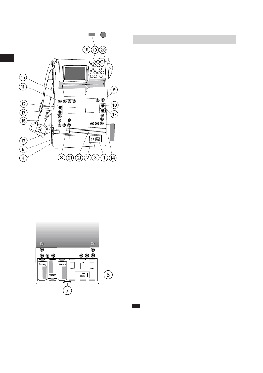
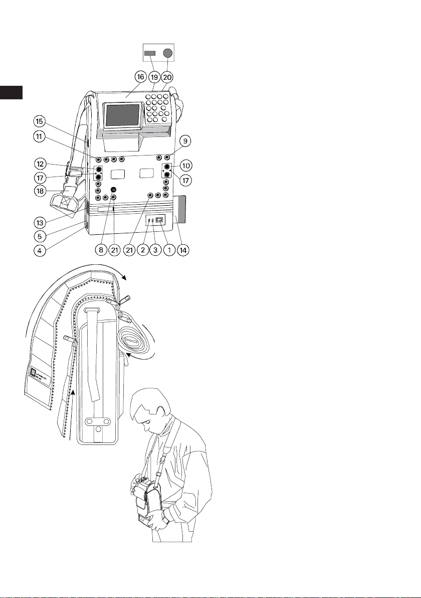
Parts identification
12
1 POWER switch
Switch to put the calibrator
"ON" and "OFF".
2 CHG. (amber LED) charging
indicator
On when batteries are charged.
The indicator should not light
when non-rechargeable
batteries are installed.
3 EXT. (green LED) external
power indicator
On when calibrator is powered
from the optional line
adaptor/charger #13603.
4 EXT. POWER INPUT
Connector for external
power source.
Only suitable for optional line
adaptor/charger #13603.
5 Battery compartment cover
Release screws to get access
to batteries.
K0320 Issue No. 1
6 Battery selector switch
To select Alkaline or
Rechargeable batteries.
Remove protective sticker to
get access to the switch.
IMPORTANT:
Switch position
must comply with installed battery
type.
Page 6
16
Functionallity
15 Pt100 PROBE
4-pole mini DIN female connector
for optional sensor.
16 Control and display panel
Rotatable unit to position best for
bench or portable use.
17 Auxilary Connectors
For use with pressure module
MCX-PM. [Do not make any other
connections to these terminals]
18 Shoulder strap (removable)
For portable use with adjustable
length.
19 VIEWING ANGLE adjustment
knob
To adjust LCD contrast.
20 BACKLIGHT Push button
Switches LCD backlight ON/OFF.
21 COMMUNICATOR TERMINALS
Connections for "smart"
Instrumentation. [Use is optional
with communicator card]
Test Equipment Depot - 800.517.8431 - 99 Washington Street Melrose, MA 02176
K0320 Issue No. 1
FAX 781.665.0780 - TestEquipmentDepot.com
Page 7

18
Functionallity
Screens to work with
The MCX-II has four types of screen
display to work with:
• Menu Selection Screen
Offers selection of choices. Move
cursor with arrow keys to your choice.
• Set up Screen
Move cursor with arrow keys to fill in
the blanks.
• Working Screen
Displays readings of measured and
generated values. Output or simulated
temperatures are set with the
numerical key-pad or can be ramped up
and down in different ways.
K0320 Issue No. 1
NOTE:
After switching the calibrator
on, the screen will show:
• Serial Serial Number
• Firmware Firmware version
• Hart Hart Firmware
version
• Battery voltage/switch position
• Days left to next calibration
Page 8
20
Functionallity
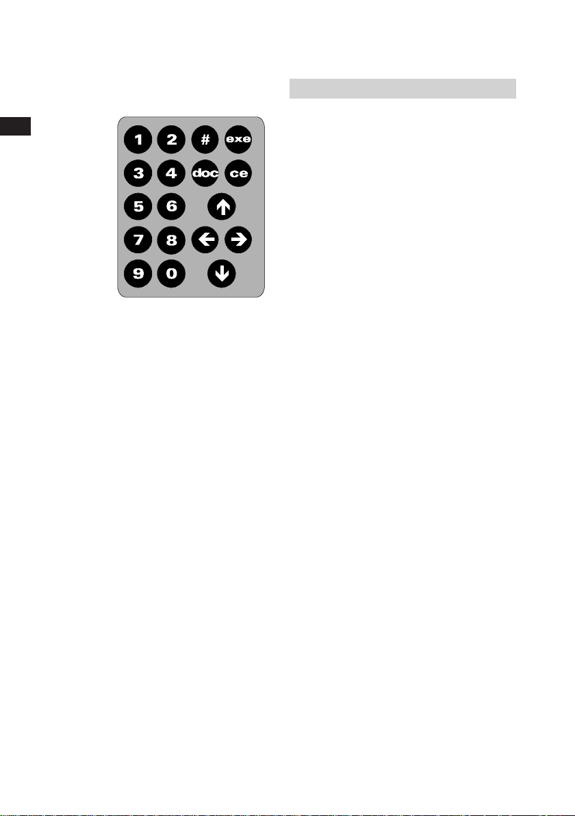
Keys to work with
• The EXE key
Pressing this key will execute choices
or output level adjustments.
• The CE key
Press to cancel your previous key
operation or to correct a typing error.
• The NUMERICAL key-pad
Used to dial output levels or
simulated temperatures. Also used to
fill out levels and time settings for
special functions.
• The ARROW keys
Moves the cursor position and ramps
output levels up or down.
• The # key
Used to open the set-up menu.
K0320 Issue No. 1
• The DOC key
Used to access the documenting
functions.
• The 0 key
Changes the sign when display reads
all zeros.
Page 9

22
Power Sources
Power from internal batteries
Internal power is obtained from
6 x 1.5 V Alkaline batteries or 6 x 1.2 V
Rechargeable batteries, Model R14, Baby
or C size.
• Installation of the batteries
Switch the calibrator off before you
install new batteries. Release both
mounting screws of the battery
compartment cover. Open the
compartment and place the new
batteries in position as indicated
in the compartment. Check for clean
poles and contact plates before you
replace the batteries.
• Use of Alkaline batteries
(supplied as standard)
The calibrator is supplied with one set
of 6x Alkaline batteries. Check that
the Battery Selector Switch is in the
"alkaline" position before replacing the
batteries. Battery switch position will
be confirmed on the screen during
start-up of the calibrator.
Replace batteries when the screen
shows the blinking battery symbol.
K0320 Issue No. 1
Page 10

24
Power Sources
IMPORTANT:
Be sure that batteries are
inserted so that they are
placed correctly with respect
to the (+) and (-) indications in
the battery compartment. If
the batteries are not inserted
correctly, they may leak and
damage the calibrator.
Do not mix old and new
batteries, or batteries of
different types (such as
carbon and alkaline.)
If the calibrator is not to be
used for a long period of time,
take out the batteries.
Remove and dispose of
worn-out batteries.
Never attempt to recharge or
short-circuit the batteries.
K0320 Issue No. 1
Page 11

Power Sources
Changing from Alkaline to
Rechargeable batteries
26
Remove the Alkaline batteries.
Remove the switch protector sticker
and slide the switch to the "Ni-Cd"
position.
Place a new protector sticker to save
the new switch position. Install 6
rechargeable batteries (purchased
locally). Battery switch position will be
confirmed on the screen during startup of the calibrator. Recharge
batteries when the screen shows the
blinking battery symbol.
CAUTION:
Do not fit alkaline or other nonrechargeable batteries after you
have changed the switch position to
"Ni-Cd".
Recharging
Use the Line Adaptor/Charger #13603
only; other equipment may cause
damage to the calibrator. Check the
indicated line volt switch in the
CHARGE position. Connect the
appropriate Adaptor/Charger plugs to
the line and to the calibrator. The
amber led CHG at the calibrator power
panel will now be on. As adaptor and
charger functions are fully
independent from each other, the
calibrator can be used while charging.
Recharging time from complete
discharge to fully charge is 14 hours.
K0320 Issue No. 1
Page 12

28
Power Sources
You may charge for periods longer
than 14 hours. Note that at lower
ambient temperatures the capacity of
Ni-Cd batteries is significantly lower. If
the batteries do not reach their normal
capacity after a 14 hours charging
period, cycle complete discharging
and charging for at least 2 times. If
batteries remain weak they should be
replaced. No particular brand of Ni-Cd
is recommended although cells rated
at 2.0 Ah have preference over
general available 1.8 Ah cells.
Operating from 115 V or 230V line voltage
(50 or 60 Hz)
Use the Line Adaptor/Charger #13603
only; other equipment may cause
damage the calibrator. Check the
indicated line voltage. Connect the
appropriate Line Adaptor/Charger
plugs to the line and to the calibrator.
The green led EXT at the calibrator will
now be on.
Test Equipment Depot - 800.517.8431 - 99 Washington Street Melrose, MA 02176
FAX 781.665.0780 - TestEquipmentDepot.com
K0320 Issue No. 1
Page 13
30
Set-up
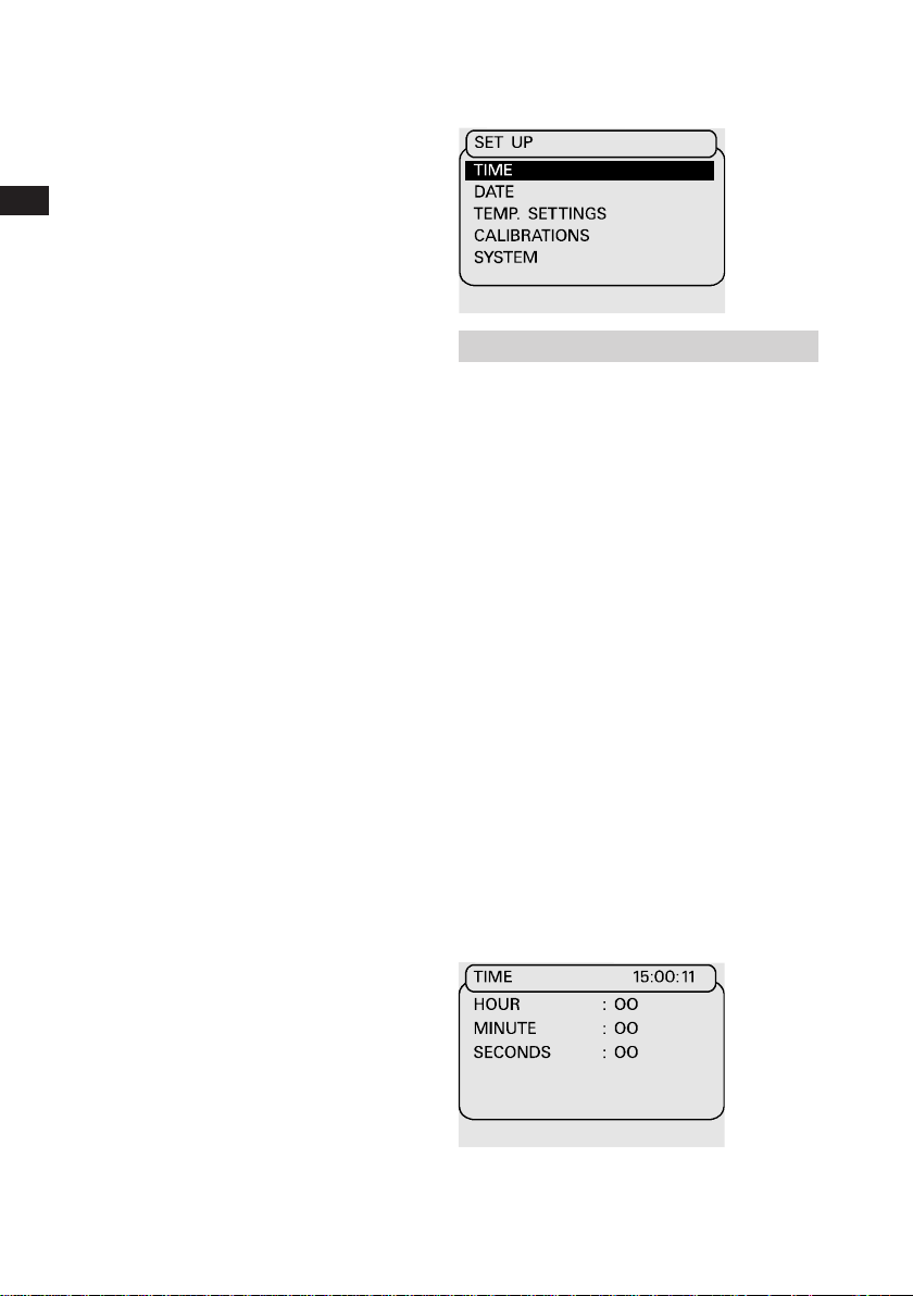
Date and Time Settings
The MCX-II has been equipped with an
internal clock: to indicate how many
days are left before last calibration
expires and to record date and time
on the memory card. The clock has
been factory set to Paris time at the
date of calibration.
Setting the clock to your local time
Leave the cursor at NONE at the
INPUT and OUTPUT menu and press
the # key to open the set-up menu.
Select TIME. Press EXE again. Enter
the local time. Press EXE to accept
new time or press CE to leave the setup menu.
K0320 Issue No. 1
Page 14
32
Set-up
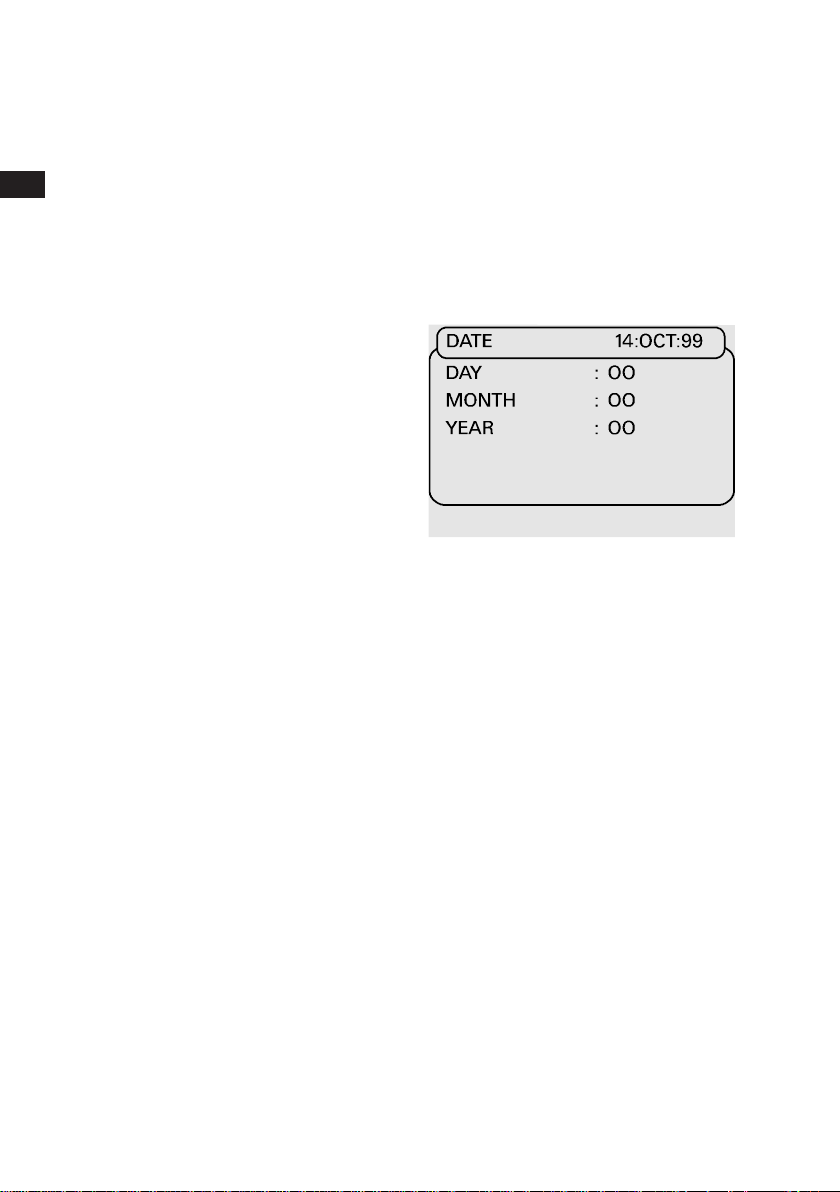
Setting the clock to your local date
Leave the cursor at NONE at the
INPUT and OUTPUT menu and press
the # key to open the set-up menu.
Select DATE. Press EXE again. Enter
date. Press EXE to accept new date or
press CE to leave the set-up menu.
K0320 Issue No. 1
Page 15
34
Set-up
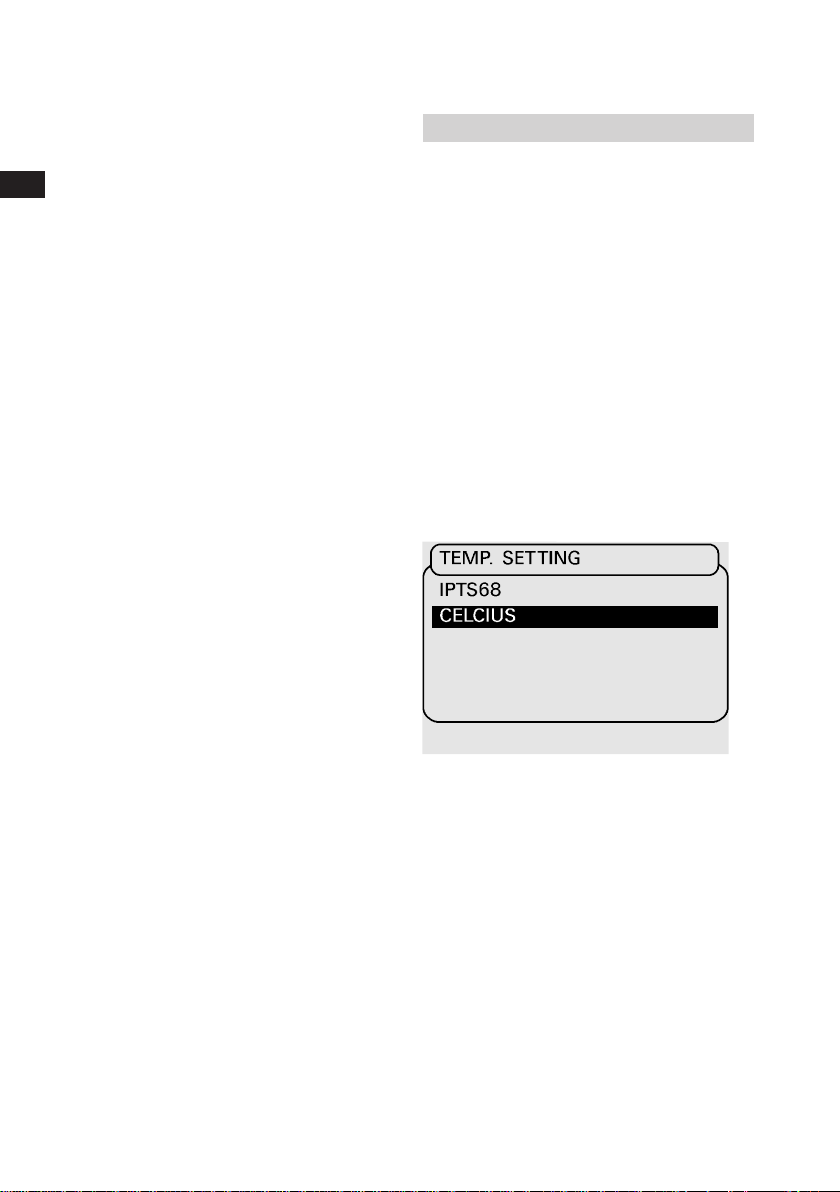
Temperature readings
Temperature simulations and
measurements can be shown in either
Celsius or Fahrenheit units. Factory
setting is Celsius. Readings are based
on either IPTS 68 or ITS 90
temperature scales.
Factory setting is ITS 90.
Changing the temperature unit
Leave the cursor at NONE at the
INPUT and OUTPUT menu and press
the # key to open the setup menu.
Select TEMP.SETTINGS and then the
temperature unit. Press EXE to
change.
K0320 Issue No. 1
Page 16
36
Set-up
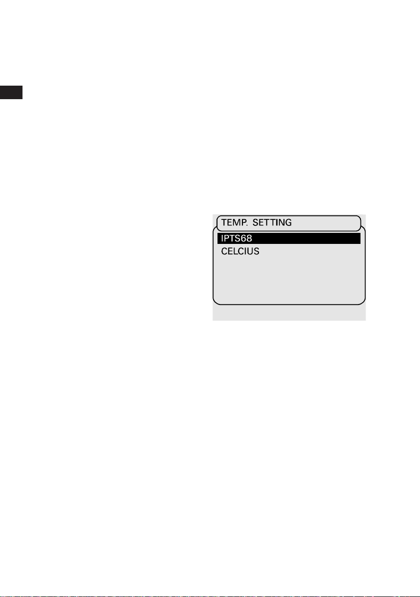
Changing the temperature scale
Leave the cursor at NONE at the
INPUT and OUTPUT menu and press
the # key to open the setup menu.
Select TEMP.SETTING and then
the temperature scale and press
EXE to change.
Select TEMP.SETTING and then
the temperature scale and press
EXE to change.
K0320 Issue No. 1
Page 17
38
Set-up
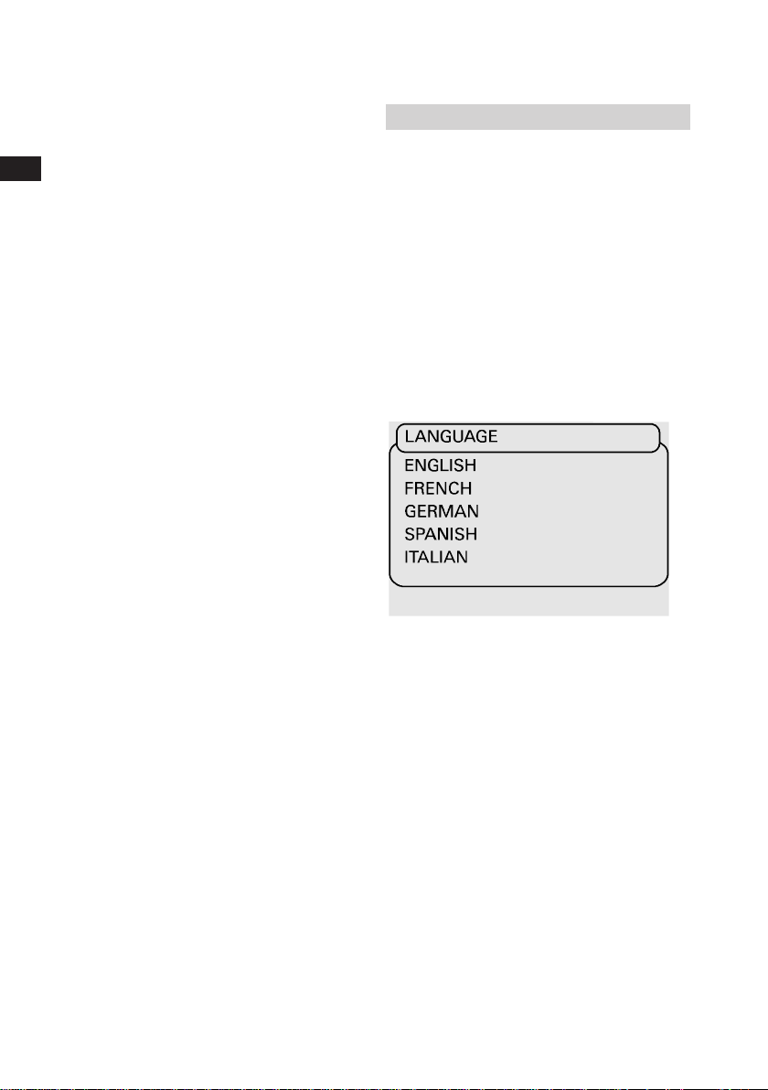
Language Setting
The MCX-II has multilingual software.
The factory setting is ENGLISH.
Setting the Language
Leave the cursor at NONE at the
measure and source menu and press
# key to open the set-up menu.
Select SYSTEM and then LANGUAGE
and press EXE. Select required
language and press EXE. Press CE to
leave the set-up menu.
K0320 Issue No. 1
Page 18

40
Set-up
Access code settings
The ACCESS CODE is programmable
by the customer. The following menus
are protected by this code;
ACCESS CODE
Calibration menu
(Electrical and pressure)
9410 is standard factory setting.
Leave the cursor at NONE at the
measure and source menu and press
# to open the set-up menu. Select
SYSTEM and press EXE. Select
ACCESS CODE and press EXE to
confirm. You are now in mode where
you can change the code. If applicable
the new code can be typed in and
confirmed by EXE. 0000 as code is
considered as no existing ACCESS
CODE.
NOTE: Registration of the
ACCESS CODE is essential.
Test Equipment Depot - 800.517.8431 - 99 Washington Street Melrose, MA 02176
FAX 781.665.0780 - TestEquipmentDepot.com
K0320 Issue No. 1
Page 19
42
Set-up
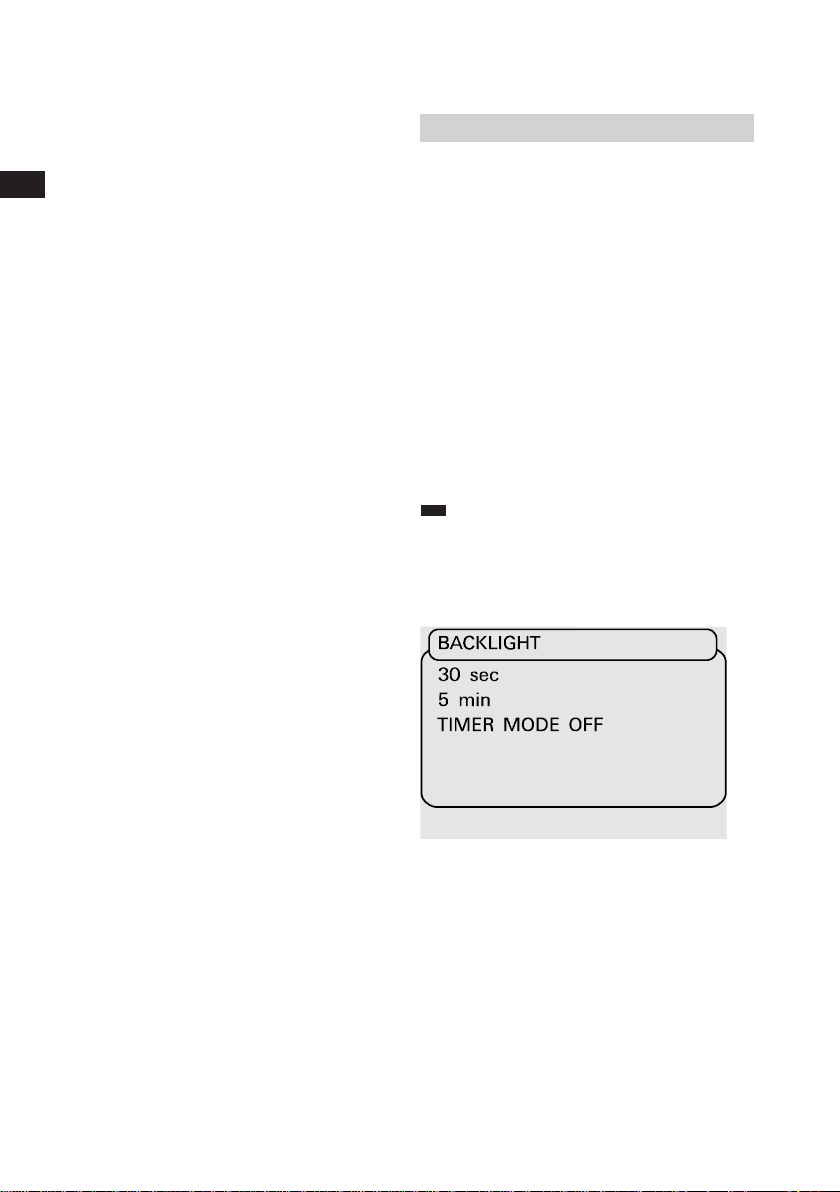
LCD screen viewing adjustments
Setting the backlight automatic shut
off mode
Leave the cursor at NONE at the
INPUT and OUTPUT menu and press
the # key to open the setup menu.
Select system and press EXE. Next
select the BACKLIGHT MODE and
press EXE.
The backlight timer can be set to
30 seconds, 5 minutes or off. select
appropriate choice and press EXE to
acknowledge. Press CE to leave the
setup menu.
NOTE:
It is recommended to
switch the BACKLIGHT MODE on to
save batteries if the unit is mainly
used in the field.
K0320 Issue No. 1
Page 20

44
Set-up
Backlight on/off operation
Press the LIGHT key to switch the
backlight ON or OFF. Each key-pad
operation will postpone shut-off for
another time period.
Screen contrast adjustment
Turn the knob for best screen contrast.
Contrast may alter with different
viewing angles.
K0320 Issue No. 1
Page 21
46
Set-up
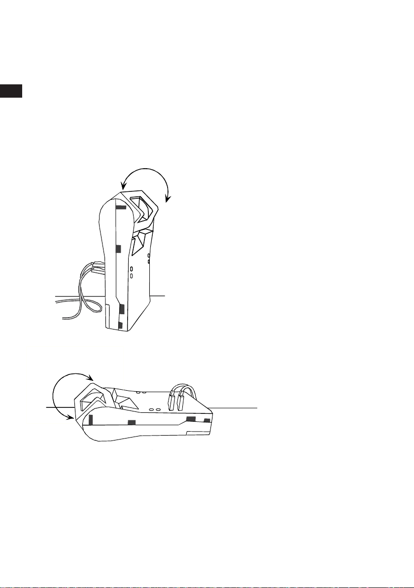
Bench or portable use
The MCX-II calibrator can be used in
the two ways as shown. Control and
Display Panel can be rotated into
5 different positions for best screen
viewing angle. Input and output
terminals are accessible from front
and back to plug-in the test leads in
the most practical way.
K0320 Issue No. 1
Page 22

48
Set-up
Keystroking
Key-stroking is a solution to eliminate
time consuming key-pad operations for
functions you frequently use. It can
store 10 different sequences of keypad operations. Recalling a sequence
will put you right back into the function
as stored. You can recall a sequence
from any operational situation.
Storing a key-pad operation
sequence
Make all the necessary arrangements
for the function you want to "keystroke". Press # to open the set-up
menu and select key-stroking. Next
select the numerical key under which
you want to store the sequence. To
store a new function under a "used"
key, repeat above procedure to
overwrite the old function.
K0320 Issue No. 1
Recalling a key-pad operation
sequence
Leave the cursor at NONE in the input
and output menu and press the
appropriate numerical key to activate
the "key-stroke".
Page 23

50
Set-up
Clear keystroking
Leave the cursor at NONE at the
measure and source menu and press
the # key to open the set-up menu.
Select CLEAR KEYSTROKING
MEMORY and press EXE. EXE will
clean the KEYSTROKE memory. Press
CE to leave the set-up menu.
K0320 Issue No. 1
Page 24

52
To measure signals
General
Select an input range and select
DIRECT from the menu. It puts you
right in the output mode. For other
modes like scaled readings read the
chapter " Special Output Functions".
The upper part of the screen shows
the window for input functions. Here,
you can read the measured value.
Millivolts
Select mV and DIRECT in the input
menu and press EXE to open the
working screen. The upper window in
the working screen indicates the
measured millivolts reading.
The range is 0-600 mV split into two
(auto) ranges of 0 to 100 mV and
100.000 to 100.01 to 600.00 mV.
Test Equipment Depot - 800.517.8431 - 99 Washington Street Melrose, MA 02176
FAX 781.665.0780 - TestEquipmentDepot.com
K0320 Issue No. 1
Page 25

54
To measure signals
Volts
Select VOLTS and DIRECT in the
measure menu and press EXE to open
the working screen. The upper window
in the working screen indicates the
measured Volts reading.
The range is 0-60 Volts split into two
(auto)ranges of 0 to 6.0000 Volts and
6.001 to 60.000 Volts.
Milliamps/XMTR
Select mA and DIRECT in the measure
menu and press EXE to open the
working screen. The upper window in
the working screen indicates the
measured milliamps reading.
The percentage of 4-20 mA is indicated
in small size digits to facilitate easy
alarm switch adjustments. The range is
0-52.000 mA.
K0320 Issue No. 1
Page 26

56
To measure signals
Ohms
Select OHMS and DIRECT in the
measure menu and press EXE to open
the working screen. The upper window
in the working screen in the indicates
the measured ohms reading.
The range is 0-2000 Ohms split into
two (auto)ranges of 0.01 to 400.00
Ohm and 400.0 to 2000.0 Ohm. The
exitation current is 0.9 mA.
The wiring can be 2, 3, or 4 wire.
The wire method is a true measurement
of voltage drop across unknown
resistance at a constant excitation
current.
Frequency
Select FREQ in the measure menu
and press EXE. Select FREQ and
DIRECT in the FREQ.menu and enter
a trigger level between 10 mV and 5V.
Press EXE to open the working
screen.
K0320 Issue No. 1
The upper window of the working
screen indicates the measured
frequency reading.
The range is 0-20.000 Hz split into
three (auto)ranges of 0-655 Hz,
655-1310 Hz and 1310-20.000 Hz.
Page 27

58
Counter
Zähler
Compteur
To measure signals
Pulse Counter Mode
There are three different modes
available:
Counts pulses up to
999.999.999
Counts the pulses received in
one minute
Counts the pulses received in
one hour
Select COUNTER in the input menu
and press EXE. Enter a trigger level
between 10 mV and 5.0 Volts. Select
COUNTER, P/MIN or P/HOUR and
press EXE to open the working screen.
Press # to set the trigger level.
K0320 Issue No. 1
NOTE:
The pulse counter starts
on the first (positive) rising edge.
Page 28

60
To measure signals
Switch position change
Connect the switch as indicated.
Select SWITCH in the measure menu.
Generate or simulate the appropriate
source signal from the MCX-II to
activate the switch. The measure
(upper) reading tracks the source
(lower) reading until the switch
position changes. This change will
immediately "freeze" the measure
reading indicating the actual switch
setting. Press the # button to reset.
The measure reading will track the
source reading again.
Make sure that NO or NC contacts are
potential free.
K0320 Issue No. 1
Page 29

62
To measure signals
Circuit continuity tester
To check wiring continuity use the
RTD input terminals identified with SW.
If NONE has been selected in the
output menu and SWITCH has been
selected in the input menu, press EXE
to enter the continuity check mode.
Closing the test loop will activate the
built-in buzzer top prove that the
wiring loop has a resistance of 2200
Ohms or less.
To calculate the switch resistance
press # to open the set-up menu and
select SWITCH RESISTANCE.
NOTE:
Remote temperature
probe should not be connected in
this mode.
K0320 Issue No. 1
Page 30

64
Thermocouples
Thermoelementen
Thermocouples
To measure a thermocouple
Go through the thermocouple input
menu and make the selections as
required. Press EXE to open the
working screen; the measurement
reading is shown in the upper window.
Resolution is 0.1 degrees for most
thermocouple types.
Using compensation wires
It is strongly recommended to use
compensation wires for thermocouple
simulations and measurements. Insert
the compensation wire lead ends into
the wire holes as indicated.
Hand-tight each terminal screw to
secure the wires and make the proper
connections at the instrument side.
Make sure that you use the right type
of wires and that polarities are not
accidentally reversed. Select
INTERNAL to compensate the cold
junction microvolts automatically.
Test Equipment Depot - 800.517.8431 - 99 Washington Street Melrose, MA 02176
FAX 781.665.0780 - TestEquipmentDepot.com
K0320 Issue No. 1
Page 31

To measure a thermocouple
Using the standard test leads (copper wires)
66
Air probe
Hand-tight the terminal screws
before plugging the test leads in.
Compensation in this case is required
to offset the cold junction
compensation microvolts generated by
the instrument under calibration.
For this we need to measure the
temperature at the instrument
terminals. Instrument terminal
temperatures can be measured by
either a hand-held thermometer or a
remote temperature probe.
• Hand-held thermometer
(not supplied by GE)
Read the thermometer while holding it
close to the instrument terminals.
Select MANUAL and open the screen
to fill out the obtained reading. Press
EXE to enter.
Note that in this mode temperature
changes at the instrument terminals
can easily create calibrations errors.
• Remote temperature probe
(optional)
Plug-in the Pt100 probe as shown and
select EXTERNAL in the menu.
Position the sensor tip as close as
practically possible to the instrument
terminals.
K0320 Issue No. 1
Page 32

68
Air probe
To measure a RTD
Go through the RTD input menu and
make the selections as required.
Press EXE to open the working
screen; the measurement reading is
shown in the upper window.
Resolution is 0.1 or 0.01 degree
depending on selected RTD type. The
excitation current is 0.9 mA. Wiring
can be 2, 3 or 4 wire.
The 4 wire method is a true
measurement of voltage drop across
the unknown resistance at a constant
excitation current.
With the remote probe (optional)
With the optional available
temperature probe or with any other
suitable type of Pt100 sensor, you can
measure temperatures easily. Select
PROBE in the input menu and press
EXE to open the working screen; the
measurement reading is shown in the
upper window when the probe has
been plugged-in as indicated. See the
connection diagram if you use other
Pt100 sensors.
Pt100
PROBE
CONNECTOR
4 POLES, MINI-DIN
K0320 Issue No. 1
Page 33

70
Special Measurement Functions
Scaled Readings
Except in temperature measure ranges
all readings can be presented in a
number of 5 digits and a sign.
This number could represent an
engineering unit like gallons/hour,
revolutions/minute or any other
relationship. This facility is available
on both measurement and source
functions. The original signal reading
is still displayed in smaller sized digits.
Setting up scaled readings
(linear relationship)
Select SCALE to open the set up
screen. Fill out the high- and low-limits
for the span (preset at 4 and 20 mA in
the milliamp ranges). Fill out both
scale ends for the new scale. Press
EXE to show the working screen.
K0320 Issue No. 1
NOTE:
Scaling in lower ranges only
when auto ranging.
Page 34

72
Special Measurement Functions
Setting up scaled readings
(flow relationship)
Only available on the mA ranges.
Select SCALE and FLOW to open the
set-up screen. High- and low-limits for
the span are preset at 4 and 20 mA.
Change span if necessary. Fill out
both scale ends for the new scale.
Press EXE to show the working
screen.
NOTE:
Readings are flow related
when simulating or reading
dP-transmitters measuring across
an orifice plate.
K0320 Issue No. 1
Page 35

74
Output of electrical signals
General
Select an output range and select
DIRECT from the menu. It puts you
right in the output mode. For other
modes read section "Special Output
Functions". The lower part of the
screen shows the window for output
functions. Here, you can read the
output level labelled with either SET
or OUTPUT.
Set mode
In the SET mode you change the
output reading without changing the
actual output at the terminals. Once
you press EXE, the output will change.
to the new setting.
K0320 Issue No. 1
Page 36

76
Output of electrical signals
Output mode
In the OUTPUT mode you change both
the output reading and the actual
output at the terminals. Entering a new
value through the numerical key-pad
brings you back into the SET mode.
Changing the output level
Use the
and keys to ramp the
output signal manually. Holding the
key down will gradually accelerate
the adjustment speed.
Enter a new output value through the
numerical key-pad and press EXE to
activate the signal at the output
terminals. Entered values outside the
range will prompt the message
OUTSIDE RANGE.
Test Equipment Depot - 800.517.8431 - 99 Washington Street Melrose, MA 02176
FAX 781.665.0780 - TestEquipmentDepot.com
K0320 Issue No. 1
Page 37

78
Output of electrical signals
Millivolts
Go to millivolts in the DIRECT mode to
output any signal between -10 mV and
100 mV. Adjustments are made with
1 microvolt resolution.
If the adjusted output level cannot be
maintained the screen will prompt the
warning CHECK LOOP.
NOTE:
‘Terminal to test lead’
junctions may create e.m.f.
microvolts causing an offset in the
actual output signal.
Millivolts output
Millivolt Geben
Sortie millivolts
K0320 Issue No. 1
Page 38

80
Volts output
Volt Geben
Sortie volt
Transmitter (XMTR) Simulation
Simulieren 2-Leiter Transmitter
Simuler un transmitter 2-fils
Output of electrical signals
Volts
Go to Volts in the DIRECT mode to
output any signal between zero and
12 Volts. Adjustments are made with
100 microvolts. If the adjusted output
level cannot be maintained the screen
will prompt the warning CHECK LOOP.
Milliamps/XMTR
Use mA terminals to source a current
into a resistor (active mode). Use
XMTR terminals to simulate a 2-wire
transmitter (passive mode). Go to
milliamps in the DIRECT mode to
output any signal between 0 and
24 mA. Adjustments are made with
1 microamps resolution. If the
adjusted output level cannot be
maintained the screen will prompt the
warning CHECK LOOP. To output
fixed 0, 4, 8, 12, 16 and 20 mA levels,
press
key to change to fixed steps.
Use
and keys to adjust the output
current. Press
key to return to
normal output mode.
K0320 Issue No. 1
Page 39

82
Output of electrical signals
Ohms
Go through the OHM menu and select
either the 0-400 or the 0-2000 Ohms
range and enter the DIRECT mode.
Resistance is simulated across the two
terminals as shown. Connecting a third
or fourth wire adapts the simulation to
3 or 4 wire input. Adjustment
resolution is respectively 0.01 Ohms
and 0.1 Ohms.
Frequency
Pulses are symmetrical square wave
and -70 mV zero based. Frequency is
set by the
and keys or numerical
key-pad. Resolution is 0.1 Volt and
amplitude is default set to 5.0 Volts.
With frequency set at 0 Hz this
function becomes available as a
voltage adjustable and regulated DC
supply. Frequency output can take
loads up to 34 mA at 24 Volts
maximum.
K0320 Issue No. 1
Frequency range 0-100 Hz
Go to pulse DIRECT mode to output any
pulse signal between zero and 100 Hz.
Adjustments are made with 0.01 Hz
resolution.
Page 40

84
Output of electrical signals
Frequency range 0-20 kHz
Go to pulse DIRECT mode to output any
pulse signal between zero and 20.000 Hz.
Adjustments are made with 1 Hz resolution.
Frequency range 0-6000 P./Min.
Same as 0-100 Hz but reads in
Pulses/Minute
Pulse output range
0 - 99 999 P./Hour
Same as 0-100 Hz but reads in
Pulses/Hour
Counter
Go to the pulse PRESET mode and
set the amplitude. Press EXE to proceed
to the working screen. Use the and
keys to move the cursor from upper to
lower line and vice versa. Fill out the
number of pulses to be transmitted as
well as the Baud rate (max. 18 000
pulses/seconds). Press EXE to start the
pulse transmission.
K0320 Issue No. 1
Page 41

86
To simulate a thermocouple
Go through the thermocouple menu
and make the selections as required.
Select the DIRECT mode to simulate
any temperature within the range of
the chosen thermocouple type.
Adjustment resolution is 0.1 degree.
For cold junction compensation
considerations and different wiring
methods read section "To measure
thermocouples" in this book.
K0320 Issue No. 1
Page 42

88
2 wire
2 Leiter
2 fils
3 wire
3 Leiter
3 fils
RTD Simulation
Go through the RTD menu and make
the selections as required. Select
DIRECT mode to simulate any
temperature within the range of the
chosen RTD type. Adjustment
resolution is 0.1 or 0.01 degree
depending on RTD type.
See specifications for details.
Resistances representing
temperatures are simulated across the
two terminals as shown. Connecting a
third or a fourth wire adapts the
simulation to 3 or 4 wire inputs.
Excitation current
The excitation current to source a
resistance should be between 0.175
and 3.500 mA. Excitation currents may
be intermittent as with some smart
temperature transmitters.
4 wire
4 Leiter
4 fils
Test Equipment Depot - 800.517.8431 - 99 Washington Street Melrose, MA 02176
FAX 781.665.0780 - TestEquipmentDepot.com
K0320 Issue No. 1
Page 43

90
Special Output Functions
Step Mode
In the step mode the MCX-II can
generate preset output levels in three
different ways;
INPUT
OHM
FREQ.
COUNT ER
SWI TCH
BATT ERY
OUT P UT
mA/ XMT
mV
VOLT
T/ C
RT D
K0320 Issue No. 1
Page 44

92
Special Output Functions
• Free programmable,
Select PROGR
Number of steps (2 to 10) and levels
are free programmable.
STEP
PROGR.
10 %
20%
30%
• 10% Divisions, Select 10%
Free programmable span is
automatically divided in 10
steps of 10% each.
• 20% Divisions, Select 20%
Free programmable span is
automatically divided in 5 steps
of 20% each.
K0320 Issue No. 1
• 25% Divisions, Select 25%
Free programmable span is
automatically divided in 4 steps
of 25% each.
Stepping through the fixed levels
can either be performed manually
or automatically.
Page 45

94
Special Output Functions
Ramp Mode
The MCX-II can generate automatically
a time linear increasing or decreasing
output signal. Signal limits are free to
set within any of the available output
ranges. Time scales can be set
between 1 and 9999 seconds.
NOTE:
The automatic ramp mode
cannot be used together with the
frequency measurement mode and
the pulse count mode.
INPUT
OHM
FREQ.
COUN TER
SWI TCH
BAT TERY
OUT P UT
mA/ XMT
mV
VOLT
T/ C
RT D
Setting up the ramp mode
Select RAMP and fill out the set-up
screen. The high-end value sets the
maximum output. The low-end value
sets the minimum output. Fill out the
required travel and dwell time in
seconds and press EXE.
K0320 Issue No. 1
Page 46

96
Special Output Functions
To start/stop a ‘one shot’ ramp
Press to start a one shot ramp for
signal increase and press
to start
this ramp for signal decrease.
Press
and simultaneously to
‘freeze’ the ramp action.
To restart press
or . Press CE to
cancel the ramping operation.
To start/stop ramp cycling
Press
and direct after each other
to start a continuous up and down
ramp cycling with dwelling at the high
and low ends. The first arrow key hit
determines the take-off direction.
Press
and simultaneously to
‘freeze’ the ramp action. To restart
press
or . Press CE to cancel the
ramping operation.
K0320 Issue No. 1
Scaled readings
Dial directly in scaled readings to SET
a related output signal as set-up.
Press EXE to actually output the signal.
The and key functions are
available to fine adjust the output.
Page 47

98
User Power supplies
Power supplies available for the user
are designed to power transmitters,
control and transducer wheatstone
bridges. The following power supplies
are available at the terminals as
indicated:
24 VDC fixed, combined with the
mA input terminals, current limited at
32 mA.
24 VDC fixed, combined with the
mA output terminals, current limited
at 32 mA.
0-24 VDC adjustable, combined with
the frequency output terminals.
Resolution is 0.1 Volt. With frequency
set at 0 Hz, output becomes available
as a voltage adjustable and regulated
power supply.
Current limited at 34 mA.
K0320 Issue No. 1
Page 48

100
Transmitter calibration
In this function transmitter source and
measure readings are both scaled in
engineering units for quick comparison.
Transmitter may be a linearized, nonlinearized, 4-20 or 0-20 mA model for
thermocouples or RTD’s.
Setting up a calibration
Leave the cursor on NONE in the
input menu and select the required
output function.
Go through the menu and make the
selections as required. In the mode
screen, select CAL to calibrate a
transmitter. Proceed to select all
transmitter characteristics.
Test Equipment Depot - 800.517.8431 - 99 Washington Street Melrose, MA 02176
FAX 781.665.0780 - TestEquipmentDepot.com
K0320 Issue No. 1
Page 49

102
Transmitter calibration
To check or calibrate a transmitter
All normal key-pad functions are
available to change the output. Use
the
key to change to fixed steps.
Use and keys to step through
0%, 25%, 50%, 75% and 100% of
the span as set-up. Press
to
return to the normal key-pad functions.
An ideal transmitter will show
equal readings. The difference of
both readings is expressed in % of
the transmitter span or reading and
is shown in the upper window in
small size digits.
K0320 Issue No. 1
Page 50

104
0-20 mA
4-20 mA
mA out
Control system
Regelsystem
Système de régulation
4-20 mA
XMTR
Control system
Regelsystem
Système de régulation
Temperature transmitter
simulation
User can dial a temperature in
degrees to output a 4-20 mA or 0-20
mA signal. This signal can be used to
simulate transmitters at control system
input terminals. The simulated
transmitter may be linearized or nonlinearized. Function is available for all
type of temperature sensors supplied
as standard in the MCX-II.
Setting up a simulation
Leave the cursor on NONE in the input
menu and select the required RTD or
T/C function (ignore the
CJ compensation menu). In the mode
screen, select SIM to simulate a
transmitter and proceed to select all
transmitter characteristics. Fill-out the
transmitter span and press EXE to
open the working screen. The lower
windows shows the MCX-II output
milliamps in small digits.
K0320 Issue No. 1
Page 51

106
Temperature transmitter simulation
To simulate a transmitter
All normal key-pad functions are
available to change the (mA) output.
Use the
key to move to fixed steps.
Use and keys to step through
0%, 25%, 50%, 75% and 100% of
the span as set-up. Press
to
return to the normal key-pad functions.
Next to the simulated temperature the
lower window shows the MCX-II
output milliamps in small size digits.
K0320 Issue No. 1
Page 52

108
Programmable signal
converter
With this unique feature any input
signal (including the probe) can be
converted into any on the MCX-II
available output signals with full
galvanic isolation. Zero and span
settings for both input and output are
fully programmable.
Setting up a signal converter
Make all input and output selections
as you would do when you use input
and output functions separately in the
DIRECT output mode. When the
normal working screen is displayed
press # to open the set-up screen and
select convert. Fill out the input- and
output span and press EXE again to
proceed to the signal converter
working screen. Actual input and
output signals are now displayed.
K0320 Issue No. 1
NOTE:
The signal converter
function can not be used in pulse
counting ranges.
Page 53

110
Ce Remarks
Ce Remarks
The MCX-II prompts EMI (ElectroMagnetic Interference) whenever the
functionality is influenced by
electromagnetic disturbances. The
results obtained during this state are
unreliable.
The MCX-II is protected against
failures by fast transient/burst. It
restarts itself whenever this situation
occurs and returns to the main screen.
K0320 Issue No. 1
In this way a save state of operation
can be assumed.
Page 54

112
Service, repair and parts
Recalibration of the MCX-II
Leave the cursor at NONE in the
INPUT and OUTPUT menu and press
the # key to open the settings menu.
Select CALIBRATION and press EXE.
Fill out the access code and press
EXE to open the calibration menu.
The access code is fixed at 9410
and works as an barrier to prevent
accidental access to MCX-II
calibration ranges.
The calibration menu shows all
relevant ranges to calibrate. Each
range can be recalibrated independent
of any other range. Only the cold
junction compensationsystem is
influenced by millivolts recalibration.
Select the ranges to be calibrated and
press EXE. Follow the instructions on
the next screens. Fill out the
calibration readings and press EXE to
confirm or to return to the calibration
menu.
Select an other range to continue
recalibration or press CE to leave
the calibration menu.
Test Equipment Depot - 800.517.8431 - 99 Washington Street Melrose, MA 02176
K0320 Issue No. 1
FAX 781.665.0780 - TestEquipmentDepot.com
Page 55

114
Service, repair and parts
Cold Junction Compensation
Calibration
To recalibrate or check the cold
junction measurement system for both
input and output, use an electronic
thermometer with a maximum error of
±0.07°C (0.13°F). Remove the
compensation wire fixation screws
from the T/C terminals. Insert the
thermometer probe in the appropriate
T/C terminal hole and make sure a
good thermal contact is made down at
the bottom of the terminal. Take
measurements samples of both
terminals and calculate the average
temperature. Enter this temperature
to recalibrate. Do not use thermal
conductivity gel as this can not easily
be removed from the terminal.
K0320 Issue No. 1
Page 56

116
Service, repair and parts
NOTES:
1. Calibration standards should
have a valid calibration
certification and should be at
least 3 times more accurate as
the published accuracies for
the MCX-II for each range.
2. As derived from electrical
parameters, temperature
sensor ranges do not require
any individual recalibration.
3. Be sure that you use the test
leads, as standard supplied
with the MCX-II or other low
e.m.f. test leads.
4. The MCX-II should be powered
from the on board batteries
during recalibration.
5. Recalibration must be carried
out at reference ambient
temperature and humidity.
MCX-II must be exposed to this
condition for at least 2 hours
before the actual recalibration
starts.
6. Recalibrate mV ranges before
starting recalibration of the
Cold Junction Compensation
system.
7. When accessing the calibration
menu the temperature unit is
set to °C and the temperature
scale is set to IPTS 68.
8. Calibration is recommended
between 12 and 14 months.
K0320 Issue No. 1
Page 57

118
Processor board p/n 25100
Processorkarte p/n 25100
Carte processeur p/n 25100
Service, repair and parts
Replacing the lithium battery
Clock problems are in most cases
caused by a weak lithium cell. To
replace the cell, open the unit as
described under chapter “fault finding
procedures”. Use a small screwdriver
to lift the cell from its socket. Remove
the cell by sliding it away. Replace by
3 Volts cell type CR2025 only.
K0320 Issue No. 1
Page 58

Service, repair and parts
120
Fault finding procedures
Opening and closing the
calibrator housing
Remove the batteries and disconnect
the unit from other equipment. Take
the four T/C wire screws out and
release all visible Phillips screws at
the back and inside the battery
compartment. Lift gently the
housing upper half off and put it away.
Disconnect the power cable from the
board and the cable to the rotatable
unit. The electronic board assembly
and the rotatable unit can now be
taken out of the lower half of the
housing.
To open the rotatable unit release the
two screws at the same half on each
side.
To close the calibrator housing in
reverse order the following must be
considered;
1. Place the rotatable unit back in the
click mechanism slots as found before.
2. Make sure that the cable between base
unit and rotatable unit is correctly
routed as indicated.
3. Put the three printed circuit board
spacers in place. Left-hand and righthand spacers have brass wire guide
tubes; make sure they fit into the mV
terminals correctly.
4. Check the "battery type" selector switch
position before turning the unit on.
K0320 Issue No. 1
Page 59

122
Service, repair and parts
Fault finding procedures
When the MCX-II doesn’t work
properly or doesn’t work at all, it is
recommended to return the unit to one
of the GE Service Centres or to your
local distributor after you have
checked the following;
Most of the problems with portable
instruments are related to power
supply defects, blown fuses or
displaced connectors.
The unit doesn’t work at all.
1. When normally line powered,
change to battery operation to
check the line adaptor.
2. When normally battery
powered, check the contact
springs for corrosion and
spring force.
K0320 Issue No. 1
3. Check total battery voltage
with a voltmeter. Alkaline
should read around 9 Volts
and NiCd’s should read
around 7.2 Volts when new or
fully charged.
4. Open the MCX-II as described
in the previous paragraph and
check whether the PCB
interconnecting plugs are still
in position.
Page 60

124
Input board p/n 25102
Eingangskarte p/n 25102
Platine d'entrée p/n 25102
Power board p/n 25101
Versorgungskarte p/n 25101
Platine alimentation p/n 25101
Service, repair and parts
5. The unit doesn’t measure
milliamps.
Check the fuse accessible
from the front. Replace fuse
only by p/n 13119 or Littelfuse
No. 217.400.
6. The unit doesn’t measure
Ohms or RTD’s
Open the MCX-II and check the
fuse on the input board.
Replace fuse only by p/n 13119
or Littelfuse No. 217.400.
7. The Optional “Communicator”
doesn’t work.
Open the MCX-II and check the
fuse on the power board.
Replace fuse only by p/n 13119
or Littelfuse No.217.400.
Most other fault symptoms are not
logically related to just one possible
defect.
When you have spare printed circuit
boards available, you could replace
board by board to find the faulty
board. Note that a board replacement
requires a recalibration. Note that this
procedure may also create a problem
in a new healthy board by specific
defects in a original board.
Test Equipment Depot - 800.517.8431 - 99 Washington Street Melrose, MA 02176
FAX 781.665.0780 - TestEquipmentDepot.com
K0320 Issue No. 1
Page 61

Kundendienst, Reparatur und Ersatzteile Maintenance, répartions et pièces détachées
5. Das Gerät mißt keine
Milliampere
Prüfen Sie die von der
Vorderseite erreichbare
Sicherung. Ersetzen Sie sie
gegebenenfalls nur durch eine
p/n 13119 oder Littelfuse Nr.
217.400.
6. Das Gerät mißt keine Ohm
oder
Widerstandsthermometer
Öffnen Sie den MCX-II und
prüfen Sie die Sicherung auf
der Eingangskarte. Ersetzen
5. L'appareil ne mesure pas le
millampères
Vérifier le fusible accessible à
l'avant. Le remplacer
uniquement par un fusible réf.
13119 ou un fusible
"Littelfuse" N
0
217.400.
6. L'appareil ne mesure pas
les ohms ou les RTD.
Ouvrir le MCX-II et vérifier le
fusible sur la carte d'entrée.
Le remplacer uniquement par
un fusible réf. 13119 ou on
fusible "Littelfuse" N
0
217.400.
Sie sie gegebenenfalls nur
durch eine p/n 13119 oder
Littelfuse Nr. 217.400.
7. Die Option "Communicator"
funktioniert nicht
Öffnen Sie den MCX-II und
prüfen Sie die Sicherung auf
der Versorgungskarte. Ersetzen
Sie sie gegeben enfalls nur
durch eine p/n 13119 oder
Littelfuse Nr. 217.400.
7. La carte de communication
optionelle ne fonctionne
pas.
Ouvrir le MCX-II
précédemment et vérifier le
fusible sur la carte
alimentation. Le remplacer
uniquement par un fusible réf.
13119 ou un fusible
"Littelfuse" N
0
217.400.
125
Die meisten anderen Fehlersymptome
stehen nicht in einer logischen
Beziehung zu einem einzigen
möglichen Fehler. Wenn Sie
Ersatzkarten zur Verfügung haben,
können Sie Karte für Karte ersetzen
und so die Fehlerhafte finden.
Bedenken Sie, daß der Austausch
einer Karte eine Neukalibrierung
erfordert. Bedenken Sie ferner, daß
durch diese vorgehensweise ein
Fehler in einer neuen intakten Karte
entstehen kann, verursacht durch
einen bestimmten Fehler in einer
Originalkarte.
La plupart des autres symptômes
peuvent avoir plusieurs causes. Si des
cartes de rechange sont disponibles,
remplacer les cartes une à une afin
d'identifier la carte défectueuse. A
noter qu'en cas de remplacement
d'une carte, il faut réétalonner
l'appareil.
Il se peut aussi que cette opération
crée un problème dans une carte
neuve saine du fait de défauts propres
à la carte d'orgine.
K0320 Issue No. 1
Page 62

Service, repair and parts
The following boards are
accommodated in the MCX-II:
126
• Power supply board p/n 25101
• Processor board p/n 25100
• Input board p/n 25102
• Output board p/n 25103
• Digital communicator board
(Optional) p/n 25107
• LCD/Key-pad processor board (in
rotatable panel) p/n 25105
• Key-pad board (in rotatable panel) p/
n 25106
For GE Sales and Service Points
see back cover.
K0320 Issue No. 1
Page 63

128
Service, repair and parts
Spare parts list
Part No.
Power board Assy 152
Processor board Assy 149
Input board Assy 153/II
Output board Assy 154
LCD display 22500
LCD display board Assy 156/II
Key-pad board Assy 157
Board spacers (3X) 25207
T/C terminal screws (2X) 25301
6x Test leads, 6x clips Assy 162
2x Switch protectors
Operating Manual 25500
Line adaptor/charger
115VAC 13603/115
Line adaptor/charger
230VAC 13603/230
Pt100 hand-held probe Assy 170
Switch protector (3X) 24003
Battery compartment
cover 25204
Set of battery
contact springs 13013/16
LCD display window 25125
Set of fuses (10X) 13119
Fuse holder 13118
Carrying case 24005
Shoulder strap 24007
Lithium cell 13183
K0320 Issue No. 1
Page 64

Electrical functions
Measure millivolts
auto.ranging
Output millivolts
130
Measure Volts
auto.ranging
Output Volts
Measure milli-ampére
Output milli-ampére
Simulate 2-wire XMT
Measure Ohms
auto.ranging
Simulate Ohms
Simulate Ohms
Measure frequency
auto.ranging
auto.ranging
Counter
Counts/minute
Counts/hour
Output frequency
Output pulses preset
Temperature functions
Pt1000 Measure
Pt500 Measure
Pt200 Measure
Pt100 Measure
Pt50 Measure
D-100 Measure
Ni100 Measure
Ni120 Measure
Cu10 Measure
Measure/Simulation TC - J
Measure/Simulation TC - L
Measure/Simulation TC - K
Measure/Simulation TC - T
Measure/Simulation TC - U
Measure/Simulation TC - B
Measure/Simulation TC - R
Measure/Simulation TC - S
Measure/Simulation TC - E
Measure/Simulation TC - N
Measure/Simulation TC - C
Measure/Simulation TC - D
Simulation
Simulation
Simulation
Simulation
Simulation
Simulation
Simulation
Simulation
Simulation
Specifications
Range
+ 0...100mV
+100...600mV
-10...100mV
+ 0...6V
+ 6...60V
0...12V
+ 0...52mA
0...24mA
4...24mA
0...400Ω
400...2000Ω
0...400Ω
0...2000Ω
0...655Hz
655...1310Hz
1310...10.000Hz
0...99999999
600000
9999999
0...100Hz
6000 p/min
0...10000Hz
99999 p/hour
0...99999999
Range
-200/400°C -328/752°F
-200/400°C -328/752°F
-200/850°C -328/1562°F
-200/850°C -328/1562°F
-200/850°C -328/1562°F
-200/850°C -328/1562°F
-200/850°C -328/1562°F
-200/850°C -328/1562°F
-200/850°C -328/1562°F
-200/850°C -328/1562°F
-200/649°C -328/1200°F
-200/649°C -328/1200°F
-60/250°C -76/482°F
-60/250°C -76/482°F
-80/260°C -112/500°F
-80/260°C -112/500°F
-200/260°C -328/500°F
-200/260°C -328/500°F
-210/1200°C -346/2192°F
-200/900°C -328/1652°F
-200/1372°C -328/2502°F
-270/-200°C -454/-328°F
-75/400°C -103/752°F
-180/-75°C -292/-103°F
-270/-180°C -454/-292°F
-100/600°C -184/1112°F
-200/-100°C -328/-184°F
1200/1820°C 2192/3308°F
500/1200°C 932/2192°F
250/500°C 482/932°F
50/250°C 122/482°F
300/1769°C 572/3216°F
-50/300°C -58/572°F
400/1769°C 752/3216°F
100/400°C 212/752°F
-50/100°C -58/212°F
-150/1000°C -238/1832°F
-270/-150°C -454/-238°F
-20/1300°C -4/2372°F
-200/-20°C -328/-4°F
-270/-200°C -454/-328°F
0/1500°C 32/2732°F
1500/2000°C 2732/3632°F
2000/2320°C 3632/4208°F
0/1700°C 32/3092°F
1700/2200°C 3092/3992°F
2200/2495°C 3992/4523°F
Resolution
0.001
0.01
0.001
0.0001
0.001
0.0001
0.001
0.001
0.001
0.01
0.1
0.01
0.1
0.01
0.1
1
1
1
1
0,01
1
1
1
1
Resolution
0.1°C 0.2°F
0.1°C 0.2°F
0.1°C 0.2°F
0.1°C 0.2°F
0.1°C 0.2°F
0.1°C 0.2°F
0.03°C 0.06°F
0.03°C 0.06°F
0.06°C 0.11°F
0.06°C 0.11°F
0.03°C 0.06°F
0.03°C 0.06°F
0.1°C 0.2°F
0.1°C 0.2°F
0.1°C 0.2°F
0.1°C 0.2°F
0.3°C 0.6°F
0.3°C 0.6°F
0.1°C 0.2°F
0.1°C 0.2°F
0.1°C 0.2°F
0.2°C 0.4°F
0.1°C 0.2°F
0.1°C 0.2°F
0.1°C 0.2°F
0.1°C 0.2°F
0.1°C 0.2°F
0.1°C 0.2°F
0.2°C 0.4°F
0.3°C 0.6°F
0.5°C 1.0°F
0.1°C 0.2°F
0.2°C 0.4°F
0.1°C 0.2°F
0.2°C 0.4°F
0.2°C 0.4°F
0.1°C 0.2°F
0.1°C 0.2°F
0.1°C 0.2°F
0.1°C 0.2°F
0.2°C 0.4°F
0.1°C 0.2°F
0.1°C 0.2°F
0.2°C 0.4°F
0.1°C 0.2°F
0.1°C 0.2°F
0.2°C 0.4°F
K0320 Issue No. 1
Page 65

1 year accuracy
0.004% Rdg. + 0.004% f.s. +1 lsd
0.005% Rdg. + 0.005% f.s. +1 lsd
0.003% Rdg. + 0.004% f.s. +1 lsd
0.009% Rdg. + 0.003% f.s. +1 lsd
0.009% Rdg. + 0.003% f.s. +1 lsd
0.004% Rdg. + 0.002% f.s. +1 lsd
0.010% Rdg. + 0.003% f.s. +1 lsd
0.010% Rdg. + 0.005% f.s. +1 lsd
0.010% Rdg. + 0.005% f.s. +1 lsd
0.005% Rdg. + 0.008% f.s. +1 lsd
0.01Hz
0.1Hz
1 Hz
infinite
1 c/min
1 c/hour
0.01Hz
1 p/min
1Hz
36 p/hour
infinite
0.012% f.s. +1 lsd
0.012% f.s. +1 lsd
0.010% f.s. +1 lsd
1 year accuracy + (abs. + 1lsd)
0.1°C 0.2°F
0.1°C 0.2°F
0.1°C 0.2°F
0.1°C 0.2°F
0.2°C 0.4°F
0.3°C 0.5°F
0.15°C 0.27°F
0.12°C 0.22°F
0.25°C 0.45°F
0.20°C 0.36°F
0.15°C 0.27°F
0.12°C 0.22°F
0.1°C 0.2°F
0.1°C 0.2°F
0.1°C 0.2°F
0.1°C 0.2°F
1.0°C 1.8°F
1.5°C 2.7°F
0.1°C 0.2°F
0.1°C 0.2°F
0.1°C 0.2°F
0.3°C 0.6°F
0.1°C 0.2°F
0.2°C 0.4°F
0.5°C 0.9°F
0.1°C 0.2°F
0.2°C 0.4°F
0.4°C 0.7°F
0.7°C 1.3°F
1.5°C 2.7°F
2.0°C 3.6°F
0.5°C 0.9°F
1.0°C 1.8°F
0.5°C 0.9°F
0.8°C 1.5°F
1.0°C 1.8°F
0.1°C 0.2°F
0.3°C 0.6°F
0.1°C 0.2°F
0.4°C 0.7°F
1.0°C 1.8°F
0.2°C 0.4°F
0.3°C 0.7°F
0.6°C 1.1°F
0.2°C 0.4°F
0.4°C 0.7°F
1.1°C 2.0°F
Remarks
R - input > 20MΩ
R - input > 20MΩ
R - output < 0.2Ω
R - input > 1MΩ
R - input > 1MΩ
R - output < 0.2Ω
R - input 2,5Ωfused
R - max. 900Ω
V-max. 56 Volts
at 0.9mA excitation
at 0.9mA excitation
at 1.0mA excitation
at 1.0mA excitation
R - input > 300kΩ
R - input > 300kΩ
R - input > 300kΩ
R - input > 300kΩ
R - input > 300kΩ
R - input > 300kΩ
0 - 24V / 34mA max.
0 - 24V / 34mA max.
0 - 24V / 34mA max.
0 - 24V / 34mA max.
0 - 24V / 34mA max.
Remarks
IEC 751
IEC 751
IEC 751
IEC 751
IEC 751
IEC 751
IEC 751
IEC 751
IEC 751
IEC 751
JIS C1604 1989
JIS C1604 1989
DIN 43760 Aug. 1985
DIN 43760 Aug. 1985
Minco 7
Minco 7
Minco 16 - 9
Minco 16 - 9
IEC 584-1
DIN 43710 Dec. 1985
IEC 584-1
IEC 584-1
IEC 584-1
IEC 584-1
IEC 584-1
DIN 43710 Dec. 1985
DIN 43710 Dec. 1985
IEC 584-1
IEC 584-1
IEC 584-1
IEC 584-1
IEC 584-1
IEC 584-1
IEC 584-1
IEC 584-1
IEC 584-1
IEC 584-1
IEC 584-1
IEC 584-1
IEC 584-1
IEC 584-1
ASTM E988-96
ASTM E988-96
ASTM E988-96
ASTM E988-96
ASTM E988-96
ASTM E988-96
131
K0320 Issue No. 1
Page 66

Special functions
132
Specifications
1 Steps; 10 programmable, 10%, 20%,
25% div. stepping by key or adj. timer
2 Ramp; programmable travel time for
up/down and dwell
3 Scaling; in 5 digits and sign on all
electrical ranges
4 Temp. XMT cal.; both input and output
readings in temp. units.
Cal.function extended for all output
functions.
5 Temp. XMT sim.; mA output reads in
temperature units
6 Signal converter; any input into any
output, fully isolated
Note: Thermocouple accuracies do not include cold junction compensation errors
Reference 22°C ±1, RH 45% ±15
Calibration Traceable to National Standards
Accuracies For 17°C to 27°C; outside these
Cold Junction error ±0.4°C (0.8 °F) max. in transient
Long term drift after 1 year 0.005% / year or 1000 hours operating
Cold Junction modes Automatic, Manual, Remote sensor
Temperature scale Selectable IPTS68 or ITS90
Warm up time 2 minutes for rated accuracies
Re-calibration From key-pad (no inside trimmers)
Operating temp. -10°C to 50°C (14°F to 122°F)
Storage temp. -20°C to 70°C (-4°F to 158°F)
Relative humidity 0 - 90% non-condensing
In-/output isolation 500VDC continuous
Electrical protection 50 Volts, 30 sec. max.
Output mismatch Displays " check loop"
limits 0.0005% / °C typical on mV
±0.2°C (0.4°F) max. when steady
Recommended for each year
Ohms out to ground; 5 Volts max.
Test Equipment Depot - 800.517.8431 - 99 Washington Street Melrose, MA 02176
FAX 781.665.0780 - TestEquipmentDepot.com
K0320 Issue No. 1
Page 67

Overrange Displays ">>>>> "
Underrange Displays "<<<<< "
Readings Temp. °C or °F
Batteries (LR14 or C) 6x 1.5V alkaline or 1.2V NiCd
Battery life Alkaline; 22 hours at 20°C (68°F)
Battery life 20 mA out Alkaline; 12 hours at 20°C (68°F)
Low battery warning Flashes a battery symbol
Line power With optional adaptor 115 - or 230VAC,
Recharge NiCd's With optional adaptor 115 - or 230VAC,
User terminals Gold plated, standard 4mm plugs
T/C comp.wire terminals Screw fixable, 2mm diameter max.
Protection IP 53
Housing Textured high-impact ABS plastic
Control panel Rotatable, 5 clicks of 30°
Size 265 x 160 x 56/80mm without case
Carrying case Black Cordura
Weight 2.2kg (5.5lbs) with batteries
Keystroking 10 operation sequences storage
Contact change detect. Reading freezes on open or close
Date and time Recorded when PCMCIA card is used
PCMCIA station PCMCIA card type 1 or 2
Detect. level freq.in Adjustable; 10mV to 5.0 Volts
Pulse output level Adjustable; 0 - 24 Volt, 0.1V resolution,
Pulse output form Symmetrical square, zero based - 70mV
Pulse output speed Adjustable in Hz or Baud rate
Remote sensor input Mini DIN Suitable for Pt100 (385 curve)
LCD display Full graphic, with contrast control and
Ohms simulation 0.18 to 3.5mA excitation current
Ohms input terminals 2, 3 or 4 wire automatic mode select.
Auxiliary connectors For use with optional pressure module
Dig. communicator board Slot supplied as standard for electronic
20 mA out NiCd; 7 hours at 20°C (68°F)
NiCd; 14 hours at 20°C (68°F)
green LED indicator
amber LED indicator
(10.6 x 6.4 x 2.2 /3.2) inch
2% accuracy
full range, 3 or 4 wire
backlight timer
either polarity
True 4 - wire system
board
133
K0320 Issue No. 1
Page 68

Specifications
Protocol for RS232 System Integration
142
Serial port settings
Bauds: 9600
Parity: none
Bits: 8
Stop: 1
Hardware handshake: none
K0320 Issue No. 1
Page 69

144
Warranty & Liability
Our equipment is warranted against
defective material and workmanship
for a period of 18 months from date of
shipment. Claims under warranty can
be made by returning the equipment
prepaid to our factory. The equipment
will be replaced, repaired or adjusted
at our option. The liability of GE is
restricted to that given under our
warranty. No responsability is
accepted for damage, loss or other
expense incurred through sale or use
of our equipment. Under no condition
shall GE be liable for any special,
incidental or consequential damage.
NOTE: Units with defects caused by
battery electrolyte from leaking
batteries are definitely excluded for
repair or replacement under
warranty.
Test Equipment Depot - 800.517.8431 - 99 Washington Street Melrose, MA 02176
FAX 781.665.0780 - TestEquipmentDepot.com
K0320 Issue No. 1
 Loading...