

Page 1
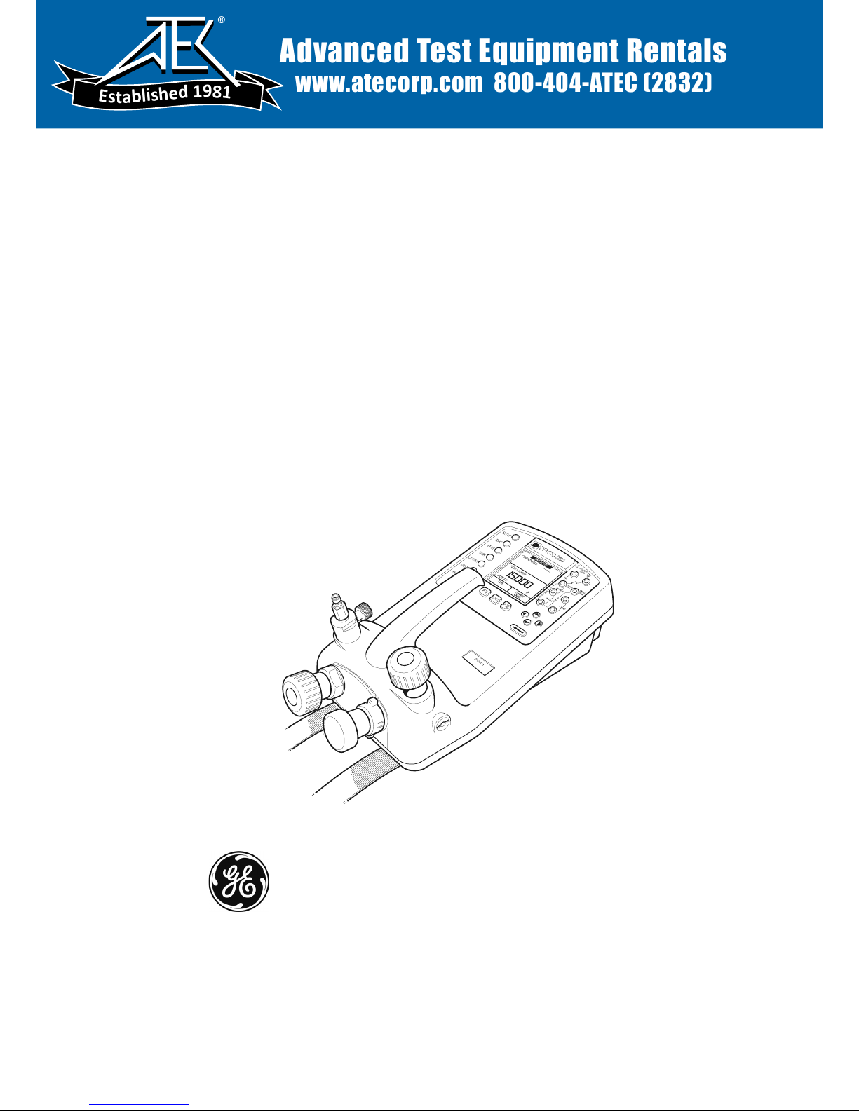
Druck DPI 610
Portable Pressure Calibrator
Aeronautical version
User manual - K0237
GE
Measurement & Control Solutions
Advanced Test Equipment Rentals
www.atecorp.com 800-404-ATEC (2832)
®
E
s
t
a
b
l
i
s
h
e
d
1
9
8
1
Page 2

© The General Electric Company. All rights reserved
Page 3
Safety
The manufacturer has designed this equipment to be safe when operated using the
procedures detailed in this manual. Do not use this equipment for any other purpose
than that stated.
This publication contains operating and safety instructions that must be followed to
ensure safe operation and to maintain the equipment in a safe condition. The safety
instructions are either warnings or cautions issued to protect the user and the equipment
from injury or damage.
Use suitably qualified * technicians and good engineering practice for all procedures in
this publication.
Pressure
Do not apply pressures greater than the safe working pressure to this equipment.
Maintenance
The equipment must be maintained using the procedures in this publication. Further
manufacturer’s procedures should be carried out by authorized service agents or the
manufacturer’s service departments.
www.gesensinginspection.com
For technical advice contact the manufacturer.
* A qualified technician must have the necessary technical knowledge,
documentation, special test equipment and tools to carry out the required work
on this equipment.
Symbols
This equipment meets the requirements of all relevant European safety
directives. The equipment carries the CE mark.
This symbol, on the instrument, indicates that the user should refer to
the user manual. This symbol, in this manual, indicates a hazardous
operation.
This symbol, on the instrument, indicates do not throw-away in
domestic bin, hazardous material, dispose correctly in accordance with
local regulations.
i K0237 Issue No. 2
Page 4

Specification
Safe working pressure
2 x full-scale
Ranges
Altitude -3000 to 50,000ft
Airspeed 0 to 600 knots
Precision
over the airspeed range:
200 knots ±3 knots
400 knots ±0.7 knots
over the altitude range:
sea level ±14 ft
10,000ft ±18 ft
30,000ft ±36 ft
Precision includes linearity, hysteresis and repeatability, 12 months measurement stability
Temperature Effects
±0.004% of reading/°C (averaged over -10° to +40°C w.r.t. 20°C)
±0.002% of reading/°F (averaged over +14° to 104°F w.r.t. 68°F)
Power supply
Batteries 6 x 1.5 V C cells, alkaline (up to 60 hours nominal use at 20°C)
Rechargeable NiCad battery pack (20 hours nominal use) supplied with charger/
adaptor, supplies power to instrument while charging batteries.
Environment
Operating Temperature: -10°C to 50°C (+14°F to 122°F)
Calibrated Temperature: -10°C to 40°C (+14°F to 104°F)
Sealing
Sealed to IP54 (NEMA 4)
Physical
Size: 300 x 170 x 140 mm (11.8” x 6.7” x 5.5”)
Weight: 3 kg (6.6lb)
For further general specification and functionality details refer to the standard DPI
610/615 Series Portable Calibrator data sheet.
Introduction 1
Pneumatic Controls 2
Electical Connections 2
Operation 3
Altitude Switch Tests 3
Altitude Leak Tests 6
Airspeed Switch Tests 8
Airspeed Leak Tests 10
K0237 Issue No. 2 ii
Contents
Page 5
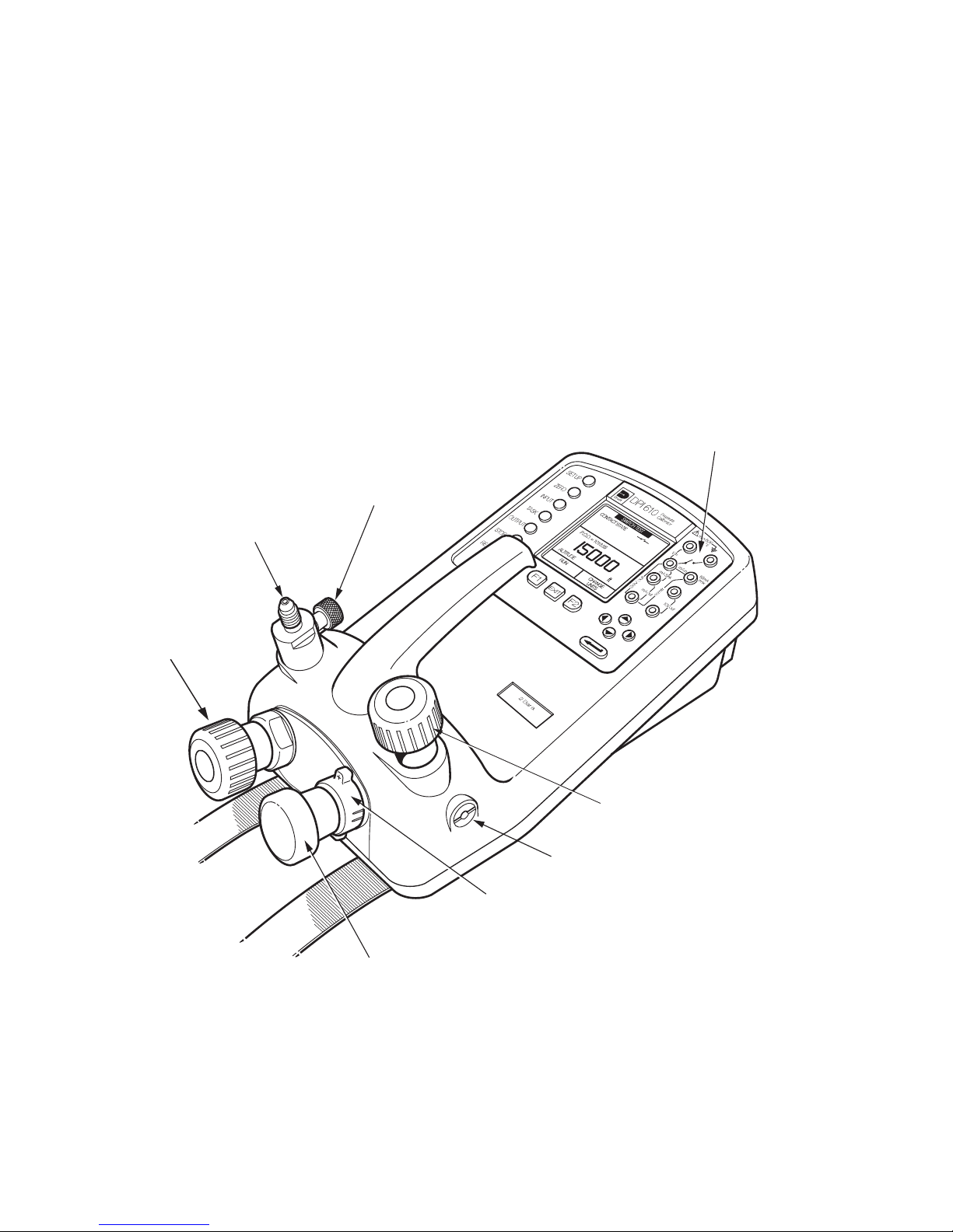
Introduction (Figure C1)
This 2 bar absolute (59 inHg absolute) version of the DPI 610 provides manual generation
of pressure and vacuum for testing of aircraft Pitot and Static systems. It has a special
pneumatic manifold and output port assembly, the regulated output of the hand-pump
prevents overpressure/vacuum of the aircraft’s Pitot and Static systems.
The generated pressure or vacuum vents to atmosphere through the vent port, the user
controls the vent rate to protect the aircraft’s systems and instruments using the release
valve.
A manual let-down valve, fitted directly in the output port, allows the system to be
manually vented (returned to ground level) by the user when the pressure or vacuum has
vented to a safe operational level i.e. < 1500 ft. The aeronautical option (AERO) can be
accessed only from the TASK menu. All other functions and tasks of the DPI 610 are
available on this version of the DPI 610 instrument.
Electrical (switch)
inputs
Manual let-down
Output port (AN4)
To pitot or static
system
valve
Fine adjustment of
either positive (pitot)
or negative (static)
pressure
Selects either
or negative (static) pressure
Hand-pump
Generates either positive (pitot)
or negative (static) pressure
Release Valve
Releases system pressure/vacuum
at a controlled rate
Vent port
positive (pitot)
Figure C1 Aeronautical Option Controls
1 K0237 Issue No. 2
Page 6

Pneumatic Controls (Figure C2)
An AN4 connector provides the output connection.
Note:
The instrument is designed to operate with 5 metres of 6mm bore pipe attached.
CLOSE
OPEN
Figure C2 - Pneumatic Controls
Electrical Connections
Refer to publication K0415 pages 6 and 7 for the fitting of batteries and the charging of
batteries.
Maximum Instrument Ratings
The following table shows the maximum measurement ratings of the standard
instrument that should not be exceeded. Pressure over range (120% of FS) is indicated
by a flashing pressure display. Voltage or current over range (110% of max) causes
either the voltage or current display to flash.
Note:
When the AERO task is selected, the display flashes if the voltage or current input over
ranges by 110% of the above maximum values. The pressure display flashes at altitudes
below -3000 ft and above 50,000 ft or at airspeeds greater than 600 knots, depending on
the mode selected.
K0237 Issue No. 2 2
Page 7

Operation
Using this version of the DPI 610 instrument, a switch test and leak test can be carried
out on an aircraft pitot or static system.
WARNING:
OBSERVE SAFETY PRECAUTIONS STATED IN LOCAL ORDERS AND
THE AIRCRAFT OR EQUIPMENT SERVICING PROCEDURES.
To select the aeronautical option from task menu, proceed as follows:
TASK
TASKS
BASIC
P-I
P-P
P-V
I-P
SELECT TASK
TASKS
ADVANCED
AERO
USER TASKS
SELECT TASK
Altitude Switch Tests
Select TASK, AERO:
Select ALTITUDE, SWITCH TEST as follows:
If necessary, SELECT AERO UNITS as follows.
ft
m
hm
3 K0237 Issue No. 2
Page 8

If required, apply pressure of the day correction (POD), by selecting POD ADJUST
as follows:
SELECT OPTION SELECT OPTION
SETUP
SETUP
BACKLIGHT
STORE MODE
CONTRAST
SETTINGS
DRY CELL LEVEL
SETTINGS
UNITS
CALIBRATION
LANGUAGE
RS232
POWERDOWN
CALIBRATION
POD ADJUST
Apply QFE pressure reading as POD correction as follows:
Note: The display can show either: POD = Off or POD = current value (QFE pressure
reading). The POD RESET key (F2) sets the current POD correction to Off.
POD=Off
POD Correction
WARNING
VENT SYSTEM
BEFORE SETTING POD
CHANGE POD
VALUE
mbar
POD RESET
POD=Off
POD Correction
WARNING
VENT SYSTEM
BEFORE SETTING POD
CHANGE POD
VALUE
ENTER VALUE
mbar
POD RESET
POD = 1002.85
POD Correction
WARNING
VENT SYSTEM
BEFORE SETTING POD
CHANGE POD
VALUE
POD RESET
Method (accessible switch contacts)
(1) Connect the instrument to the static system and connect the altitude switch as
shown. Ensure that the pitot system is vented to atmosphere before starting the test:
Note:
Contacts must be potential free.
Applied Static System Pressure
Vent Pitot System (Atmospheric Pressure)
Altitude Switch
S
mbar
Figure C3 - Altitude Switch Test Connections
(2) Select negative pressure and close the release valve.
K0237 Issue No. 2 4
Select
Negative (-)
Pressure
CONTACT STATE
POD = 1008.63
ALTITUDE
RUN
SWITCH TEST
ft
F2F1
Page 9

(3) Close the manual let-down valve.
(4) Press the RUN key (F1) and operate the hand-pump, continue until the switch
operates:
SWITCH TEST SWITCH TEST SWITCH TEST
CONTACT STATE
POD=Off
CONTACT STATE
CLOSED AT 5550 ft
POD=Off
CONTACT STATE
CLOSED AT 5550 ft
OPENED AT 5325
HYSTERESIS 225ftft
POD=Off
MANUAL
ft
ALTITUDE
STOP
OPERATION
ft
MANUAL
ALTITUDE
RUN
ft
ALTITUDE
STOP
OPERATION
(5) Carefully open the release valve and allow altitude to decrease until the switch
operates again. The display shows the operating pressures and hysteresis.
(6) Record the displayed operating data.
(7) Allow the indicated altitude to decrease until it is below 1500ft.
(8) Slowly open the manual let-down valve to return the system to ground level.
(9) To perform another switch test press RUN (F1).
(10) To cancel switch test mode, press TASK.
Method (non-accessible switch contacts)
When the altitude switch contacts cannot be connected to the instrument, an external
indicator or annunciator must be used as the indication of pressure switch operation.
The user, on receipt of an indication of switch operation, presses the MANUAL OPERATION
(F2) key:
(1) Connect the instrument to the static system.
to atmosphere before starting the test:
(2) Select negative pressure and close the release valve.
(3) Close the manual let-down valve.
(4) Press the RUN key (F1) and operate the hand-pump, continue until indication of
switch operation and immediately press (F2).
(5) Carefully open the release valve and allow the altitude to decrease until the
indication of switch operation and immediately press (F2).
Ensure that the pitot system is vented
5 K0237 Issue No. 2
Page 10

(6) Record the displayed operating data.
(7) Allow the indicated altitude to decrease until it is below 1500ft.
(8) Slowly open the manual let-down valve to return the system to ground level.
(9) To perform another switch test, press RUN (F1).
(10) To cancel switch test mode, press TASK.
Altitude Leak Tests
Select TASK, AERO:
Select ALTITUDE LEAK TEST:
If necessary, SELECT AERO UNITS:
Method
(1) Connect the instrument to the static system and, if required, apply a pressure
correction value of the pressure of the day (POD) as detailed on page 6.
(2) Close the release valve and manual let-down valve, using the hand-pump,
generate the required altitude.
(3) Set WAIT and DURATION of the leak test times:
ALTITUDE
WAIT
DURATION
CION
START ALT.
STOP ALT.
ALT. CHANGE
LEAK RATE
CHANGE
VALUE
ft
60
secs
secs
60
ft
ft
ft
ft/m
RUN
SET WAIT TIME SET DURATION
ALTITUDE
WAIT
DURATION
CION
START ALT.
STOP ALT.
ALT. CHANGE
LEAK RATE
CHANGE
VALUE
ft
60
secs
secs
60
ft
ft
ft
ft/m
RUN
K0237 Issue No. 2 6
Page 11

(4) When ready, press the RUN key (F2):
Initially, the WAIT period counts-down, followed by the TIMING period. The START
ALT is recorded as soon as the timing period starts. At the end of the test the
display shows the complete details of the test.
(5) Record the displayed operating data.
(6) To perform another leak test, use the hand-pump to generate a new system
altitude and press RUN (F2) again.
(7) On completion of the test, allow the altitude to decrease until it is below 1500 ft.
(8) Slowly open the manual let-down valve to return the system to ground level.
(9) To exit or cancel leak test mode, press TASK.
7 K0237 Issue No. 2
Page 12

Airspeed Switch Tests
Select TASK, AERO:
Select AIRSPEED SWITCH TEST:
If necessary, SELECT AERO UNITS:
Method (accessible switch contacts)
(1) Connect the instrument to the pitot system and connect the airspeed switch as shown:
Ensure that the static system is vented to atmosphere before starting the test.
Note:
Contacts must be potential free.
Applied Pitot System Pressure
Vented Static System
(Atmospheric Pressure)
CONTACT STATE
AIRSPEED
SWITCH TEST
RUN
AIRSPEED
SWITCH
P
S
kts
SELECT
POSITIVE (+)
PRESSURE
Figure C4 - Airspeed Switch Test Connections
K0237 Issue No. 2 8
F2F1
Page 13

(2) Ensure that positive pressure is selected and close the release valve.
(3) Close the manual let-down valve.
(4) Zero the airspeed reading by pressing the ZERO key.
(5) Press the RUN key (F1) and operate the hand-pump, continue until the switch
operates:
(6) Carefully open the release valve and allow airspeed to decrease until the switch
operates again. The display shows the operating airspeeds and hysteresis.
(7) Record the displayed operating data.
(8) Allow the airspeed to decrease until it is below 80 kts.
(9) Slowly open the manual let-down valve to return system to zero (ground level).
(10) To perform another switch test, press RUN (F1) and repeat the above procedure.
(11) To cancel switch test mode, press TASK.
Method (non-accessible switch contacts)
When the airspeed switch contacts cannot be connected to the instrument, an external
indicator or annunciator must be used as indication of airspeed switch operation. The
user, on receipt of an indication of switch operation, presses the MANUAL OPERATION (F2)
key:
(1) Connect the instrument to the pitot system as shown in Figure C4. Ensure that
the static system is vented to atmosphere before starting the test.
(2) Ensure that positive pressure is selected and close the release valve.
(3) Close the manual let-down valve.
(4) Zero the airspeed reading by pressing the ZERO key.
9 K0237 Issue No. 2
Page 14

(5) Press the RUN key (F1) and operate the hand-pump, continue until the switch
operates and immediately press (F2).
(6) Carefully open the release valve and allow the airspeed to decrease until the
switch operates again and immediately press (F2). The display shows the
operating airspeeds and hysteresis.
(7) Record the displayed operating data.
(8) Allow the airspeed to decrease until it is below 80 kts.
(9) Slowly open the manual let-down valve to return system to zero (ground level).
(10) To perform another switch test, press RUN (F1).
(11) To cancel switch test mode, press TASK.
Airspeed Leak Tests
Select TASK, AERO:
Select AIRSPEED LEAK TEST:
If necessary, SELECT AERO UNITS:
Method
(1) Connect the instrument to the pitot system as shown in Figure C4. Ensure that
the static system is vented to atmosphere before starting the test.
(2) Close the release valve and manual let-down valve and, using the hand-pump,
generate the required airspeed.
K0237 Issue No. 2 10
Page 15

(3) Set WAIT and DURATION of leak test times:
(4) When ready, press the RUN key (F2):
Initially, the WAIT period counts down, followed by the timing period. The START
SPEED is recorded as soon as the timing period starts. At the end of the test the
display shows the complete details of the test.
(5) Record the displayed operating data.
(6) Allow the airspeed to decrease until it is below 80 kts.
(7) Slowly open the manual let-down valve to return the system to zero (ground
level).
(8) To perform another leak test, use the hand-pump to generate a new airspeed
and press RUN (F2) again.
(9) To exit or cancel leak test mode, press TASK.
11 K0237 Issue No. 2
Page 16

intentionally left blank
K0237 Issue No. 2 12
Page 17

Page 18

 Loading...