

Page 1
Druck
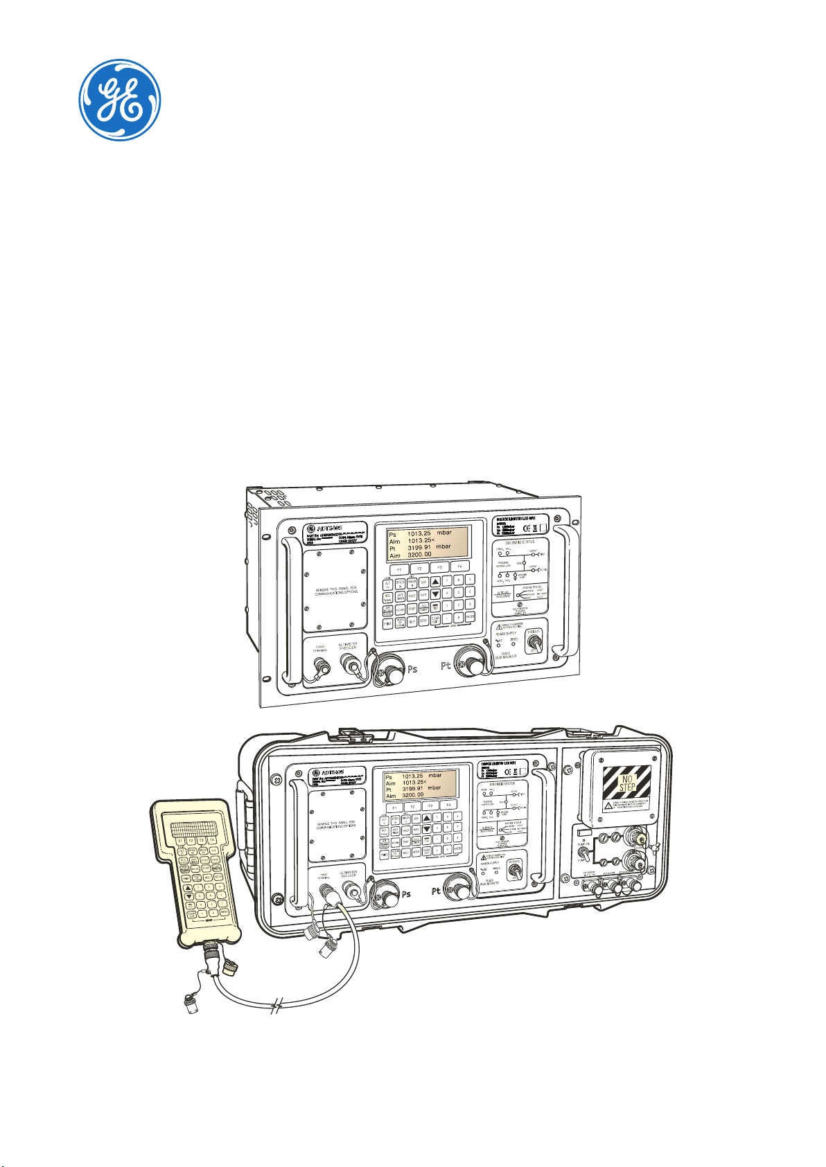
ADTS 405 R/F Mk2
Air Data Test Set
Instruction Manual
ADTS HAND TERMINAL
GE Data Classification: Public
500VA
POWERSUPPLY24-30V
FUSES
T32A
T20A
POWERSUPPLY
100/120/230V~50/60Hz500VA
115~400Hz500VA
FUSES
T5.0A250VHRC
www.gemeasurement.com
Page 2

Page 3

INTRODUCTION
This technical manual provides operating instructions for the Druck Air Data Test System ADTS 405
Mk 2 series.
SCOPE
This technical manual contains a brief description, operation and testing procedures for the user of this
equipment.
SAFETY
The manufacturer has designed this equipment to be safe when operated using the procedures
detailed in this manual:
• Do not use this equipment for any other purpose than that stated.
the protection given by the equipment from working.
• See Product Safety and Installation Guide 124M8686, also supplied, for essential operating
and Safety instructions that must be followed to ensure safe operation.
• Use suitably qualified Technicians and good engineering practice for all procedures in this
publication.
*A qualified technician must have the necessary technical knowledge, documentation,
special test equipment and tools to carry out the required work on this equipment.
Incorrect use can prevent
PRESSURE
Do not apply pressure greater than the maximum safe working pressure specified in this manual
when using the ADTS405 Mk 2 series.
TOXIC MATERIALS
There are no known toxic materials used in this equipment.
MAINTENANCE
The equipment must be maintained using the manufacturer’s procedures and should be carried out
by authorized service agents or the manufacturer’s service departments.
For technical advice contact GE or subsidiary manufacturer of this product.
© 2015 General Electric Company – All rights reserved. ADTS 405 Mk2 Instruction Manual-English | i
Page 4
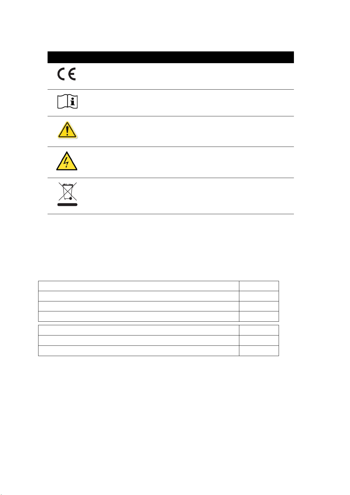
MARKS AND SYMBOLS ON THE EQUIPMENT
Symbol Description
This equipment meets the requirements of all relevant European safety
directives. The equipment carries the CE mark.
This symbol on the equipment indicates that the user should refer to the
user manual.
This symbol on the equipment indicates a warning and that the user should
refer to the user manual.
This symbol warns the user of the danger of electric shock.
Do not dispose of this product as household waste. Use an approved
organization that collects and/or recycles waste electrical and electronic
equipment. For more information contact your Customer Service using the
details shown at the back, or your local Government Office.
For the list of approved GE service centers go to: www.gemeasurement.com
ASSOCIATED PUBLICATIONS
The following table lists the Druck publications referenced in this manual:
Safety and Installation Guide - Air Data Test Systems ADTS 405F/ 405R 124M8686
Calibration Manual -
IEEE 488 OPT 2 Manual -
SCPI IEEE 488 Manual -
User Manual -
User Manual -
Operating and Communications Manual -
Altimeter Encoder Option K0170
Line Switching Unit LSU 100/101
Air Data Test System ADTS 405
Air Data Test System ADTS 405
Air Data Test System ADTS 405
Line Switching Unit LSU Series
K0199
K0154
K0157
K0220
K0223
ii | ADTS 405 Mk2 Instruction Manual-English © 2015 General Electric Company – All rights reserved.
Page 5

ABBREVIATIONS
The following abbreviations are used in this manual; the abbreviations are the same in the singular
and plural.
Abbreviation Description
A Ampere
abs Absolute
a.c. Alternating current
ALT Altitude
CAS Calibrated airspeed
d.c. Direct current
e.g. For example
EOC End of conversion
EPR Engine pressure ratio
EPROM Electrically programmable read only memory
etc. And so on
Fig. Figure
ft Foot
g Gauge
Hg Mercury
Hz Hertz
IAS Indicated airspeed
i.e. That is
IEEE 488 Institute of Electrical and Electronic Engineers standard 488 data
in inch
kg Kilogram
LED Light emitting diode
(M) Magnesium alloy
m Meter
mA Milliampere
max Maximum
mbar Millibar
mV Millivolts
No. Number
N.m. Newton meter
Para. Paragraph
Ps Static pressure
psi Pounds per square inch
© 2015 General Electric Company – All rights reserved. ADTS 405 Mk2 Instruction Manual-English | iii
Page 6

Abbreviation Description
Pt Total pressure (pitot)
Qc Differential pressure Pt-Ps
QFE Local atmospheric pressure
QNH Barometric pressure at sea level
ROC Rate of climb
Vc Calibrated velocity
Vt True velocity
+ve Positive
-ve Negative
°C Degrees Celsius
iv | ADTS 405 Mk2 Instruction Manual-English © 2015 General Electric Company – All rights reserved.
Page 7

GLOSSARY
The terminology used in this manual is specific and individual interpretation must not be
introduced. The terms are defined as follows:
Item Description
Adjust To bring to a more satisfactory state; to manipulate controls, levers, linkages, etc. to
return equipment from an out-of-tolerance condition to an in-tolerance condition.
Align To bring into line; to line up; to bring into precise adjustment, correct relative
position or coincidence.
Assemble To fit and secure together the several parts of; to make or form by combining parts.
Calibrate To determine accuracy, deviation or variation by special measurement or by
comparison with a standard.
Check Make a comparison of a measure of time, pressure, temperature, resistance,
dimension or other quality with a known figure for that measurement.
Disconnect To detach the connection between; to separate keyed or matched equipment parts.
Dismantle To take apart to the level of the next smaller unit or down to all removable parts.
Ensure To confirm that a proper condition exists; to find out with certainty.
Examine To perform a critical visual observation or check for specific conditions; to test the
condition of.
Fit Correctly attach one item to another.
Inspect Review the work carried out by Specialists to ensure it has been performed
satisfactorily.
Install To perform operations necessary to properly fit an equipment unit into the next
larger assembly or system.
Maintain To hold or keep in any particular state or condition especially in a state of efficiency
or validity.
Operate Ensure that an item or system functions correctly as far as possible without the use
of test equipment or reference to measurement.
Readjust To adjust again; to move back to a specified condition; to bring back to an in-
tolerance condition.
Reconnect To rejoin or refasten that which has been separated.
Refit Fit an item which has previously been removed.
Remove To perform operations necessary to take an equipment unit out of the next larger
assembly or system. To take off or eliminate. To take or move away.
Repair To restore damaged, worn out or malfunctioning equipment to a serviceable, usable
or operable condition.
Replace Remove an item and fit a new or a serviced item.
Reset To put back into a desired position, adjustment or condition.
Service To perform such operations as cleaning, lubricating and replenishing to prepare for
use.
Test Ascertain by using the appropriate test equipment that a component or system
functions correctly.
© 2015 General Electric Company – All rights reserved. ADTS 405 Mk2 Instruction Manual-English | v
Page 8

RETURNED GOODS PROCEDURE
If the unit is unserviceable and requires a repair return to a GE Service Centre. Contact the GE
Service Centre, either by 'phone, fax or e-mail to obtain a Returned Goods Authorization (RGA)
number, providing the following information:
• Product (i.e. ADTS 405)
• Pressure medium (i.e. air, nitrogen)
• Serial number
• Details of defect/work to be undertaken
• Operating conditions
SAFETY PRECAUTIONS
See Safety and Installation Guide 124M8686
Note: Do not use unauthorized sources to service this equipment as this will affect the
warranty and may not guarantee further performance.
PRESSURE UNITS AND CONVERSION FACTORS
Pressure units Factor (hPa) Pressure units Factor (hPa)
mbar 1.0 cmH
bar 1000.0 mH
Pa (N/m2)0.01 kg/m
hPa 1.0 kg/cm
kPa 10.0 torr 1.333223684
MPa 10000.0 atm 1013.25
mmHg @ 0°C 1.333223874 psi 68.94757293
cmHg @ 0°C 13.33223874 lb/ft
mHg @ 0°C 1333.223874 inH
inHg @ 0°C 33.86388640341 inH2O @ 20°C 2.486413
mmH
O @ 4°C 0.0980665 inH2O @ 60°F 2.487641558
2
O @ 20°C 0.978903642
2
O @ 20°C 97.8903642
2
2
2
2
O @ 4°C 2.4908891
2
0.0980665
980.665
0.4788025898
O @ 4°C 0.980665 ftH2O @ 4°C 29.8906692
cmH
2
O @ 4°C 98.0665 ftH2O @ 20°C 29.836983
mH
2
mmH
vi | ADTS 405 Mk2 Instruction Manual-English © 2015 General Electric Company – All rights reserved.
O @ 20°C 0.097890364 ftH2O @ 60°F 29.8516987
2
Page 9

Unit Conversion
To convert FROM pressure Value 1(in pressure Units)1 TO pressure Value 2 in pressure
Units: Calculate as follows:
Value 2 = Value 1 x Factor 1 ÷ Factor 2
© 2015 General Electric Company – All rights reserved. ADTS 405 Mk2 Instruction Manual-English | vii
Page 10

viii | ADTS 405 Mk2 Instruction Manual-English © 2015 General Electric Company – All rights reserved.
Page 11

Contents
1. DESCRIPTION 1
1.1 Introduction 1
1.2 Operating Range and Performance 1
1.3 Operating Limits 2
2. INSTALLATION 5
2.1 List of Parts 5
2.2 Packaging for Storage or Transportation 5
2.3 Power Supply 9
2.3.1 405R Rack-mounted version 9
2.3.2 405F Flightline version 9
2.4 Positioning of the ADTS 10
2.4.1 405R Rack-mounted version 10
2.4.2 405F Flightline version 10
3. OPERATION 15
3.1 Preparation 15
3.2 Start-up 15
3.2.1 Connections 15
3.2.2 Power-up 16
3.2.3 Units of Measure 18
3.3 Operation quick reference 19
3.4 Operating modes 20
3.5 Operating Procedures 24
3.5.1 Control or Measure Parameter 24
3.5.2 Aim 28
3.5.3 Leak Measure 29
3.5.4 Aircraft system protection 31
3.5.5 Limit Checking 31
3.5.6 Changing Parameters 33
3.5.7 Engine Pressure Ratio (EPR) 34
3.6 Testing Aircraft Systems or UUT 35
3.6.1 Go To Ground and Shut-down 35
3.6.2 SETUP and CONFIGuration options 36
3.7 Communications panel options 45
3.7.1 Ethernet System 45
3.7.2 Access ADTS files 47
3.7.3 Connection of the IEEE 488 Facility 48
3.8 Enabling the Altimeter Encoder Option 49
4. MAINTENANCE 51
4.1 Introduction 51
4.2 Materials 51
© 2015 General Electric Company – All rights reserved. ADTS 405 Mk2 Instruction Manual-English | ix
Page 12

4.3 Maintenance Tasks 52
4.4 Routine Maintenance 53
4.4.1 Servicing Procedures 53
4.4.2 Replacing the output connector o-ring 53
4.4.3 Fuse Replacement 53
4.5 Cable tests 56
5. TESTING AND FAULT FINDING 59
5.1 Introduction 59
5.2 Error messages 59
5.3 Standard Serviceability Test 60
5.3.1 Procedure 60
5.3.2 Fault Finding 61
5.4 Fault Diagnosis 62
5.5 Ventilating after Overpressure 63
5.6 Further Testing 65
5.6.1 Environmental and preliminary operations 65
5.6.2 Pressure Leak check 65
5.6.3 Vacuum leak check 66
5.6.4 Range Check 66
5.6.5 Controller Stability 66
5.6.6 Testing of Standard and Optional External Communication Ports 67
5.6.7 Testing of IEEE 488 Facility 68
5.6.8 Testing the Altimeter Encoder Option 69
6. REFERENCE AND SPECIFICATION 71
6.1 Introduction 71
6.2.1 F1 - F4 72
6.2.2 ALT/Ps 72
6.2.3 SPEED/Qc 72
6.2.4 MACH/Pt 73
6.2.5 EPR 73
6.2.6 ROC/Ps RATE 73
6.2.7 RATE TIMER 73
6.2.8 HOLD 74
6.2.9 RATE 75
6.2.10 LEAK MEASURE/CONTROL 75
6.2.11 GROUND 76
6.2.12 [GO TO GROUND] 76
6.2.13 [DISPLAY QFE] 76
6.2.14 [DISPLAY QNH] 77
6.2.15 PORT 77
6.2.16 REMOTE 77
6.2.17 PRINT 77
6.2.18 EXECUTE TEST PROGRAM 78
6.2.19 HELP 79
6.2.20 or (Nudge Keys) 79
6.2.21 Number 0 to 9 79
6.2.22 -000 80
x | ADTS 405 Mk2 Instruction Manual-English © 2015 General Electric Company – All rights reserved.
Page 13

6.2.23 CLEAR/QUIT 80
6.2.24 ENTER 80
6.2.25 CLEAR + ENTER (ABORT) 80
6.2.26 SETUP 81
6.2.27 FULL SET-UP 81
6.2.28 SETUP, [UNITS] 81
6.2.29 SETUP, [LIMITS] 82
6.2.30 SETUP, [OSC] 82
6.2.31 SETUP, [MORE], [CONTROL], [Ps Pt DUAL] 83
6.2.32 SETUP, [MORE], [DISPLAYS/OPTIONS], [DISPLAY TYPE] 83
6.2.33 SETUP, [MORE], [DISPLAYS/OPTIONS], [OPTIONS] 85
6.2.34 SETUP, [MORE], [CLOSE OUTPUT VALVES] 85
6.2.35 SETUP, [MORE], [OPEN OUTPUT VALVES] 85
6.2.36 SETUP, [MORE], [SYSTEM SELF TEST] 85
6.2.37 SETUP, ALT (Figures 6-5 and 6-6) 86
6.2.38 SETUP, SPEED, [AUTO ZERO] 86
6.2.39 SETUP, SPEED, [CAS/TAS] 86
6.2.40 SET-UP, SPEED, [Pt TEMPERATURE] 87
6.2.41 SET-UP, MACH 87
6.2.42 SET-UP, RATE TIMER 88
6.2.43 SET-UP, RATE 88
6.2.44 SETUP, LEAK MEASURE CONTROL, [AUTO LEAK] 88
6.2.45 SETUP, LEAK MEASURE CONTROL, [AUTO LIMIT] 88
6.2.46 SETUP, GROUND 88
6.2.47 SETUP, [PORT] 88
6.2.48 SETUP, PRINT, [DATE/TIME] 88
6.2.49 SETUP, EXECUTE TEST PROGRAM 89
6.2.50 SETUP, HELP 89
6.2.51 SETUP, or (Nudge keys) 89
6.2.52 MINIMUM SETUP 89
6.2.53 SETUP, [UNITS], [AERO] 89
6.2.54 SETUP, [UNITS], [PRESS] 89
6.2.55 SETUP, [LIMITS] 90
6.2.56 SETUP, HELP 90
6.2.57 CONFIGURATION 90
6.2.58 CONFIG, [UNITS] 91
6.2.59 CONFIG, [LIMITS], [EDIT LIMITS], [EDIT EXISTING] 91
6.3 ADTS 405R/F Specification 97
6.4 Measurement and Control Range Specifications 99
© 2015 General Electric Company – All rights reserved. ADTS 405 Mk2 Instruction Manual-English | xi
Page 14

xii | ADTS 405 Mk2 Instruction Manual-English © 2015 General Electric Company – All rights reserved.
Page 15

Figures
Figure Page
2-1 Equipment and Parts 7
2-2 ADTS 405R Altitude Reference 10
2-3 ADTS 405F Altitude Reference 11
2-4 ADTS 405R Front Panel View 11
2-5 ADTS 405R Rear Panel 12
2-6 ADTS 405F General View 13
3-1 Front Panel 18
3-2 Single Display 25
3-3 Dual Display 25
3-4 Triple Display 26
3-5 Rate Timer Display Aeronautical Units 26
3-6 Rate Timer Display Pressure Units 27
3-7 Pt Only Display 27
3-8 Set-up example 36
3-9 Configuring Windows For ADTS Subnet IP Address 45
3-10 Ping Test From Windows Command Prompt 46
3-11 PuTTY Configuration 46
3-12 Changing the default password 47
3-13 WinSCP Login Screen 47
3-14 ADTS File System Directories Screen 48
4-1 Output Connector O ring Seal 53
4-2 ADTS 405F AC Fuse Positioning 54
4-3 ADTS 405F DC Fuse Positioning 55
4-4 ADTS 405R AC Fuse Positioning 56
5-1 Fault Finding Chart 62
5-2 External Communications 67
6-1 Altitude Correction Rack Mounting 87
6-2 ALTITUDE CORRECTION ON-AIRCRAFT 87
6-3 ARINC 565 OPERATING LIMITS 93
© 2015 General Electric Company – All rights reserved. ADTS 405 Mk2 Instruction Manual-English | xiii
Page 16

xiv | ADTS 405 Mk2 Instruction Manual-English © 2015 General Electric Company – All rights reserved.
Page 17

Tables
Table Page
2-1 ADTS MK2 SPARES AND ACCESSORIES LIST 8
2-2 DC Input Connector 10
3-1 Units of Measure 18
3-2 Warning Messages 32
3-3 IEEE 488 facility 49
4-1 Maintenance Chart 51
4-2 Materials List 51
4-3 Tool and Test Equipment Requirements 52
4-4 AC Input Connector 57
4-5 DC Input Connector 57
5-1 Error Messages 59
5-2 Fault Advice and Action 63
5-3 Optional cable (AAU-32 units) 69
6-1 Aeronautical Units Dual Display 83
6-2 Pressure Units Dual Display 84
6-3 Aeronautical units triple display 84
6-4 Pressure units triple display 85
© 2015 General Electric Company – All rights reserved. ADTS 405 Mk2 Instruction Manual-English | xv
Page 18

xvi | ADTS 405 Mk2 Instruction Manual-English © 2015 General Electric Company – All rights reserved.
Page 19

Introduction
1. DESCRIPTION
1.1 Introduction
There are two versions of this Air Data Test System, a 19", 6U high (10½”) rack-mounted unit (ADTS
405R) and a flight line unit (ADTS 405F).
The ADTS 405R is a rack-mounted system and, with external pressure and vacuum supplies
connected, provides measurement and control of pitot and static systems and components. The
unit can be used for leak checks, calibration accuracy checks and functional tests of air data
instruments, components and systems.
The ADTS 405F is a self-contained flight-line air data test system providing complete pitot and
static measurement and control. The unit can be used for on-aircraft sense and leak testing,
calibration accuracy checks and functional tests of air data instruments, components and systems.
The ADTS 405F comprises an electronics rack and pump rack enclosed in a high density,
polyethylene case.
The ADTS 405 displays and operates in either units of pressure measurement or aeronautical units.
In the control mode, the rate that the pressures change towards new set-points can be controlled
in true aeronautical rate units.
There are two independent pneumatic channels connect to the aircraft or instrument systems, one
for static and one for pitot. They can be operated as measure only channels with leak testing facility
or each can be control channels producing true pressure conditions for altitude and airspeed.
To protect sensitive instruments and equipment a “ground” facility automatically and safely
controls both channels to atmospheric pressure at the previously entered rates of change and then
informs the operator when both channels are safely at “ground”.
The operator interface is either a hand terminal connected to the front panel or the key pad and
display on the front panel. Both provide information and control selections for the user through the
keys and display. The keypad has a back-light for improved operation in poor light conditions. The
unit can also be controlled remotely using the IEEE488 communications interface. The front panel
contains the operate switch and a mimic panel with LED indicators showing the operation of the
solenoid-operated pneumatic valves.
The pump rack, on the ADTS 405F, produces pressure and vacuum supplies for the electronics rack
and for external services. Located on the front panel, the external connectors provide for external
pressure and vacuum supplies (EXT PRESSURE and EXT VACUUM) and an auxiliary static (vacuum)
output (AUX). The rack is cooled by a fan located under a protective cover on the front panel. The
power supply connection for the ADTS 405F is located on the front panel.
1.2 Operating Range and Performance
The ADTS 405 is supplied in one of two full-scale ranges (850 knots or 1000 knots) for
measurement and control of the pitot pressure channel.
Operating limits are set, pre-defined tabular limits known as STANDARD, CIVIL and MAX these can
be selected through the SETUP menu (see Reference section 6). Operators may also configure the
display to aeronautical or pressure units but should be aware that when units of pressure are
selected, wider full-scale pressure limits will be enabled for some parameters.
© 2015 General Electric Company – All rights reserved. ADTS 405 Mk2 Instruction Manual-English | 1
Page 20

Chapter 1. DESCRIPTION
1.3 Operating Limits
The following sets of operating limits are supplied with the ADTS 405.
850 knot range operating limits
Parameter Max Limits Standard Limits Civil Limits
Min Alt -3,000 ft -2,000 ft -1,000 ft
Max Alt 105,000 ft 80,000 ft 50,000 ft
Min CAS -100 kts 0.0 kts 0 kts
Max CAS 850 kts 850 kts 450 kts
Min Ps 3.0 mbar 27.615 mbar 115.972 mbar
Max Ps 1355.00 mbar 1088.657 mbar 1050.406 mbar
Min Qc -1,352.00 mbar 0.0 mbar 0.0 mbar
Max Qc 1,700.00 mbar 1688.00 mbar 368.01 mbar
Max Mach 12.35 2.5 1
Max ROC 100,000 ft/min 9,000 ft/min 6,000 ft/min
Max Rate CAS 2,000 kts/min 600 kts/min 600 kts/min
Max Rate Ps 10,000.00 mbar/min 200.00 mbar/min 100.00 mbar/min
Max Rate Qc 10,000.00 mbar/min 200.00 mbar/min 100.00 mbar/min
ARINC Limits OFF OFF OFF
Alt Correction 0 ft 0 ft 0 ft
2 | ADTS 405 Mk2 Instruction Manual-English © 2015 General Electric Company – All rights reserved.
Page 21

Operating Limits
1000 knot range operating limits
Parameter Max Limits Standard Limits Civil Limits
Min Alt -3,000 ft -3,000 ft -1,000 ft
Max Alt 105,000 ft 80,000 ft 50,000 ft
Min CAS -100 kts 0.0 kts 0 kts
Max CAS 1,000 kts 1,000 kts 450 kts
Min Ps 3.0 mbar 27.615 mbar 115.972 mbar
Max Ps 1355.00 mbar 1,128.029 mbar 1050.406 mbar
Min Qc -1,352.00 mbar -16.303 mbar 0 mbar
Max Qc 2,500.00 mbar 2,490.50 mbar 368.01 mbar
Max Mach 14.97 5 1
Max ROC 1000,000 ft/min 15,000 ft/min 6,000 ft/min
Max Rate CAS 2,000 kts/min 700 kts/min 600 kts/min
Max Rate Ps 10,000.00 mbar/min 200.00 mbar/min 100.00 mbar/min
Max Rate Qc 10,000.00 mbar/min 200.00 mbar/min 100.00 mbar/min
ARINC Limits OFF OFF OFF
Alt Correction 0 ft 0 ft 0 ft
© 2015 General Electric Company – All rights reserved. ADTS 405 Mk2 Instruction Manual-English | 3
Page 22

Chapter 1. DESCRIPTION
4 | ADTS 405 Mk2 Instruction Manual-English © 2015 General Electric Company – All rights reserved.
Page 23
List of Parts
2. INSTALLATION
Special request
Please keep the special packing boxes so that the ADTS can be safely shipped for calibration, repair
or storage.
2.1 List of Parts
On receipt of the ADTS 405 check the contents of the packaging against the following lists:
Standard Packaging List - ADTS 405F Standard Packaging List - ADTS 405R
i) Flight line ADTS 405F i) Rack ADTS 405R
ii) Accessory bag ii)
Power supply cable 2m or 10m (regional plug
iii)
as per order)
iv) Hand terminal (optional) iv) Input, hose, 15m, green, AN6 - open
v) Hand terminal cable - 2 m (optional) v) Input, hose, 15m, yellow, AN4 - open
vi) Hand terminal cable - 18 m (optional) vi) Kit, fuse/o-ring
vii) User Manual K0572 (this publication) vii) Plug, expansion port
viii) Kit, fuse/o-ring viii) Safety and Installation Guide 124M8686
Power supply cable 2.5m (regional plug as per
order)
iii) User Manual K0572 (this publication)
ix) Safety and Installation Guide 124M8686
2.2 Packaging for Storage or Transportation
WARNING THE FLIGHT-LINE UNIT CAN BE MOVED BY USE OF THE HANDLE AND
WHEELS, BUT IF IT IS TO BE LIFTED, IT IS A TWO PERSON LIFT.
Environment
The optimum conditions for ADTS405 Mk2 equipment during transit, preparation for calibration and
repair and when being storage are detailed as below. Items in storage are defined as being nonoperational. If the ADTS becomes exposed to moisture or very high humidity, dry as soon as
possible and temporarily store in a low humidity area. The following conditions apply for storage or
shipping:
Temperature Range -51° to 70°C (-60° to +158°F)
Altitude Up to 50,000 feet (15,240 metres)
Procedure
1. The unit should be at zero/ambient pressure.
2. Disconnect all hose assemblies and stow them in the shoulder bag.
3. Switch power OFF and disconnect from the electrical power supply.
4. Disconnect the power supply cable and the hand terminal cable.
5. Disconnect the hand terminal cable from the hand terminal.
© 2015 General Electric Company – All rights reserved. ADTS 405 Mk2 Instruction Manual-English | 5
Page 24

Chapter 2. INSTALLATION
When using packing materials other than the original, proceed as follows:
1. Wrap unit in polyethylene sheeting.
2. Select a double-wall cardboard container. Inside dimensions must be at least 15 cm
greater than the equipment. The carton must meet test strength requirements of >125 kg.
3. Protect all sides with shock-absorbing material to prevent equipment movement within
the container.
4. Seal carton with approved sealing tape.
5. Mark carton “FRAGILE” on all sides, top, and bottom of shipping container.
Note: For ADTS 405R rack units loose or peripheral items should be placed in a
sealed polythene bag. For ADTS 405F stow the power supply cable, hand
terminal cable and the hand terminal in the ADTS 405F lid. Fit the lid to the
unit.
6 | ADTS 405 Mk2 Instruction Manual-English © 2015 General Electric Company – All rights reserved.
Page 25
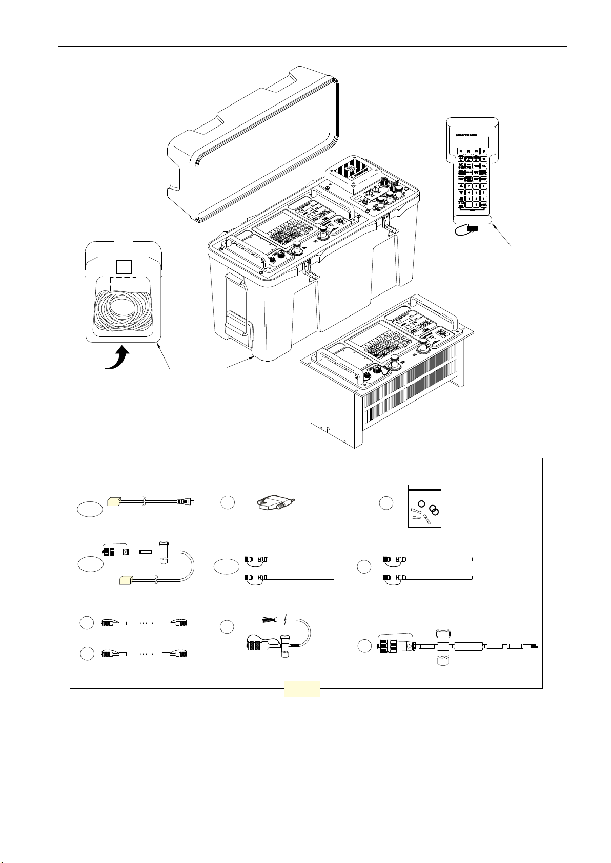
SHOULDER BAG
Packaging for Storage or Transportation
HAND TERMINAL
ADTS 405F
2
ADTS 405R
A
4a-h
5a-p
REGIONAL LINE PLUG
AC CABLE (ADTS 405F)
6
7
HAND TERMINAL CABLES
3
2.5mREGIONAL LINE PLUG
AC CABLE (ADTS 405R)
2m or 10m
2m
18m
IEC
1
ACCESSORIES
8
EXPANSION PORT DONGLE
(ADTS 405R ONLY)
9a-d
OPTIONAL CONFIGURABLE
ORDER ITEMS
AIRCRAFT HOSES
(Ps / Pt, RED / BLUE)
10
ALTIMETER ENCODER CABLE (OPTION)
11
SERVICE KIT
12
SERVICES HOSES (ADTS 405R ONLY)
PRESSURE / VACUUM, YELLOW / GREEN
15m
13
DC CABLE (OPTION)
A
Figure 2-1: Equipment and Parts
© 2015 General Electric Company – All rights reserved. ADTS 405 Mk2 Instruction Manual-English | 7
Page 26

Chapter 2. INSTALLATION
Table 2-1: ADTS MK2 SPARES AND ACCESSORIES LIST
Item Part Number Description Used On
1 - FLIGHTLINE ASSEMBLY (configured order item)
2 AS405-111-1728M0
3 AS505-57-3124M0 Accessory Bag
4a
†4b*
†4c*
†4d*
†4e*
†4f
†4g*
†4h*
5a
5b
5c
5d
5e
5f
5g
5h
5i
5j
5k
5l
5m
5n
5o
5p
6
7*
8
9a
9b
9c
9d
10
11
12
13
AA405F-23
AA405F-24
AA405F-25
AA405F-26
AA405F-27
AA405F-28
AA405F-29
AA405F-30
AA405F-1
AA405F-2
AA405F-3
AA405F-4
AA405F-5
AA405F-6
AA405F-7
AA405F-8
AA405F-9
AA405F-10
AA405F-11
AA405F-12
AA405F-13
AA405F-14
AA405F-15
AA405F-16
AS405-33-1891M0
AS405-34-1891M0
AS405-22-1891M0 EXPANSION PORT DONGLE ADTS 405R
AA500F-19
AA500F-20
AA500F-22
AA500F-23
AS405-60-1891M0
AS405-82-1891M0
AS405-53-1729M0 /
AS405-54-1729M0
AS405-31-1891M0 POWER CABLE DC (OPTION) ADTS 405F
* not illustrated
† option
HAND TERMINAL ASSEMBLY ADTS 405F/R
IEC 60320 to UK Style, BS1363
IEC 60320 to USA/Canada style, NEMA 5-15P
IEC 60320 to European style, Schuko CEE 7/7
IEC 60320 to Australia/New Zealand style, AS/NZS4417
(AS3112)
IEC 60320 to India style, IS 1293 (IA16A3, BS546)
IEC 60320 to China style, GB 15934 (GB 2099, GB1002)
IEC 60320 to South Africa style, SANS 164-1
(SANS 60799, BS546)
IEC 60320 to Japan style, JIS 8303 (NEMA 5-15P)
LEAD, AC POWER, UK, 2m
LEAD, AC POWER, UK, 10m
LEAD, AC POWER, USA, 2m
LEAD, AC POWER, USA, 10m
LEAD, AC POWER, EUROPE, 2m
LEAD, AC POWER, EUROPE, 10m
LEAD, AC POWER, NEW ZEALAND, 2m
LEAD, AC POWER, NEW ZEALAND, 10m
LEAD, AC POWER, INDIA, 2m
LEAD, AC POWER, INDIA, 10m
LEAD, AC POWER, CHINA, 2m
LEAD, AC POWER, CHINA, 10m
LEAD, AC POWER, SOUTH AFRICA, 2m
LEAD, AC POWER, SOUTH AFRICA, 10m
LEAD, AC POWER, JAPAN, 2m
LEAD, AC POWER, JAPAN, 10m
LEAD, HAND TERMINAL 2 M
LEAD, HAND TERMINAL 18 M
HOSE, RED (state length in metres)
HOSE, BLUE (state length in metres)
CONNECTOR, HOSE, AN4 FEMALE
CONNECTOR, HOSE, AN6 FEMALE
ALTIMETER ENCODER CABLE
FUSE/O-RING KIT
HOSE SET, PRESS. / VAC. YELL. / GRN.
ADTS 405F
ADTS 405F
ADTS 405R
ADTS 405F
ADTS 405F/R
ADTS 405F/R
ADTS 405F/R
ADTS 405F/R
ADTS 405F/R
ADTS 405F/R
ADTS 405F/R
ADTS 405F/R
ADTS 405R
Examine all equipment to be used, paying particular attention to electrical leads and connectors
and pneumatic pipes and connectors.
CAUTION DO NOT USE ANY EQUIPMENT THAT IS KNOWN TO BE OR SUSPECTED TO BE
DAMAGED OR FAULTY.
8 | ADTS 405 Mk2 Instruction Manual-English © 2015 General Electric Company – All rights reserved.
Page 27

2.3 Power Supply
See Safety and Installation Guide 124M8686 for full details.
AC Input
AC power supply
100 / 120 / 230V ~ 50 / 60Hz
115V ~ 400Hz 500VA
DC Input (Option ADTS405 F only)
DC power supply
24 - 30V
500VA
2.3.1 405R Rack-mounted version
Power Supply
1. The unit must be connected to the correct electrical power supply as stated, beside the
power connectors on the rear panel.
2. Install an easily accessible isolator in the power supply circuit.
3. The power supply connector on the rear panel of the unit will not be accessible when fitted
in the equipment rack.
Note: The power supply switch on the front panel is not classified as a
disconnecting device.
On the ADTS 405R, two 20mm High Breaking Capacity fuses are located in the holder mounted on
the power input connector on the rear of the rack and protect the entire unit. The fuses are
connected in the live and neutral supply circuit and are: T5A/250V HRC type. Only replace the fuses
with the correct type, see Figure 2-1 item 11 section 4-4.
2.3.2 405F Flightline version
1. The power switch on the front panel is not a power isolator as defined by EN61010. To
isolate the power supply disconnect the power supply connector.
Fuses AC Power
The fuses fitted in the fuse holders on the front panel are: T5A/250V HRC type. Only replace a fuse
with the correct type, see Figure 2-1, item 11. To replace a fuse see Section 4-4.
Fuses DC Power
The fuses fit in the fuse holders on the front panel are either: T20.0A/250V HRC type (on the left) or
T32A/250V HRC type (on the right). The DC power option (nominal 28 V DC), can be an alternative
power supply using an additional connector located on the pump front panel. Only replace a fuse
with the correct type, see Figure 2-1, item 11 To replace a fuse see, Section 4-4.
© 2015 General Electric Company – All rights reserved. ADTS 405 Mk2 Instruction Manual-English | 9
Page 28
Chapter 2. INSTALLATION
Table 2-2: DC Input Connector
ADTS Pin Cable Colour Function
1 Grey + 28V
2 White 0V Return
EARTH Green Protective Ground
CAUTION A protective EARTH connection must also be made for DC operation or
specified EMC performance may be impaired.
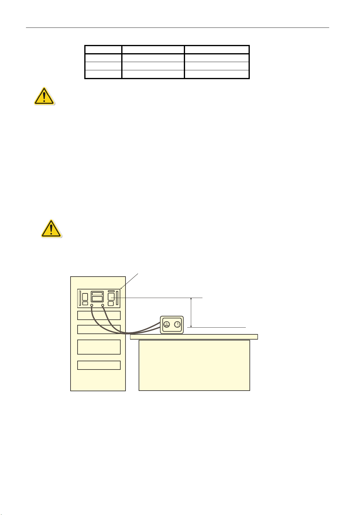
2.4 Positioning of the ADTS
2.4.1 405R Rack-mounted version
It is important that the position of the ADTS 405 in relation to the UUT is known. An altitude
correction must be made to allow for the difference in height between the reference level, indicated
on the mimic panel, and the UUT. The Reference section contains details of altitude correction
(SETUP, ALTITUDE).
WARNING OBSERVE THE APPROPRIATE SAFETY INSTRUCTIONS AND PROCEDURES
DETAILED IN THE AIRCRAFT MAINTENANCE MANUAL AND COMPONENT MAINTENANCE
MANUALS.
rack-mounted ADTS 405R
ADTS panel marked reference level
requires negative
UUT
Corrected altitude output = true altitude output increased by height difference
Figure 2-2: ADTS 405R Altitude Reference
altitude correction value
entered when below ADTS
UUT reference level
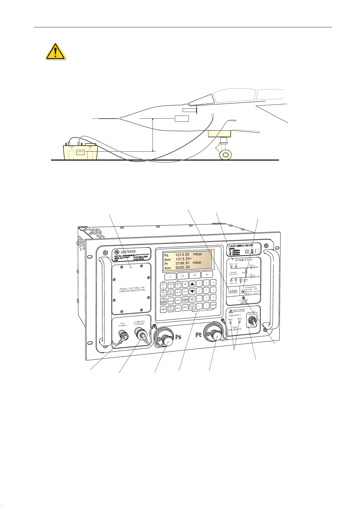
2.4.2 405F Flightline version
It is important that the position of the ADTS 405F in relation to the aircraft altitude sensors is
known. An altitude correction must be made to allow for the difference in height between the
reference level and the aircraft's altitude sensors. The Reference section contains details of altitude
correction (SETUP ALTITUDE).
10 | ADTS 405 Mk2 Instruction Manual-English © 2015 General Electric Company – All rights reserved.
Page 29
Positioning of the ADTS
WARNING THE ADTS SHOULD NOT BE PLACED IN CONTACT WITH HAZARDOUS FUEL
VAPOUR CONCENTRATIONS.
Instruments
Aircraft reference level
requires positive
altitude correction value
entered when above ADTS
ADTS reference level
Air Data
Computer
Corrected altitude output = true altitude output decreased by height difference
Figure 2-3: ADTS 405F Altitude Reference
STATIC
PITOT
Cover plate for
communications
connectors
Hand
terminal
connector
Altimeter
encoder
connector
(option)
Static
output
connector
Altitude sensor
datum height
Key-pad
and
display
Solenoid valve
status indicator
Pitot output
connector
Figure 2-4: ADTS 405R Front Panel View
Power
connection
indicators
System
status
indicator
Calibration
enable
switch
Power supply
switch
© 2015 General Electric Company – All rights reserved. ADTS 405 Mk2 Instruction Manual-English | 11
Page 30
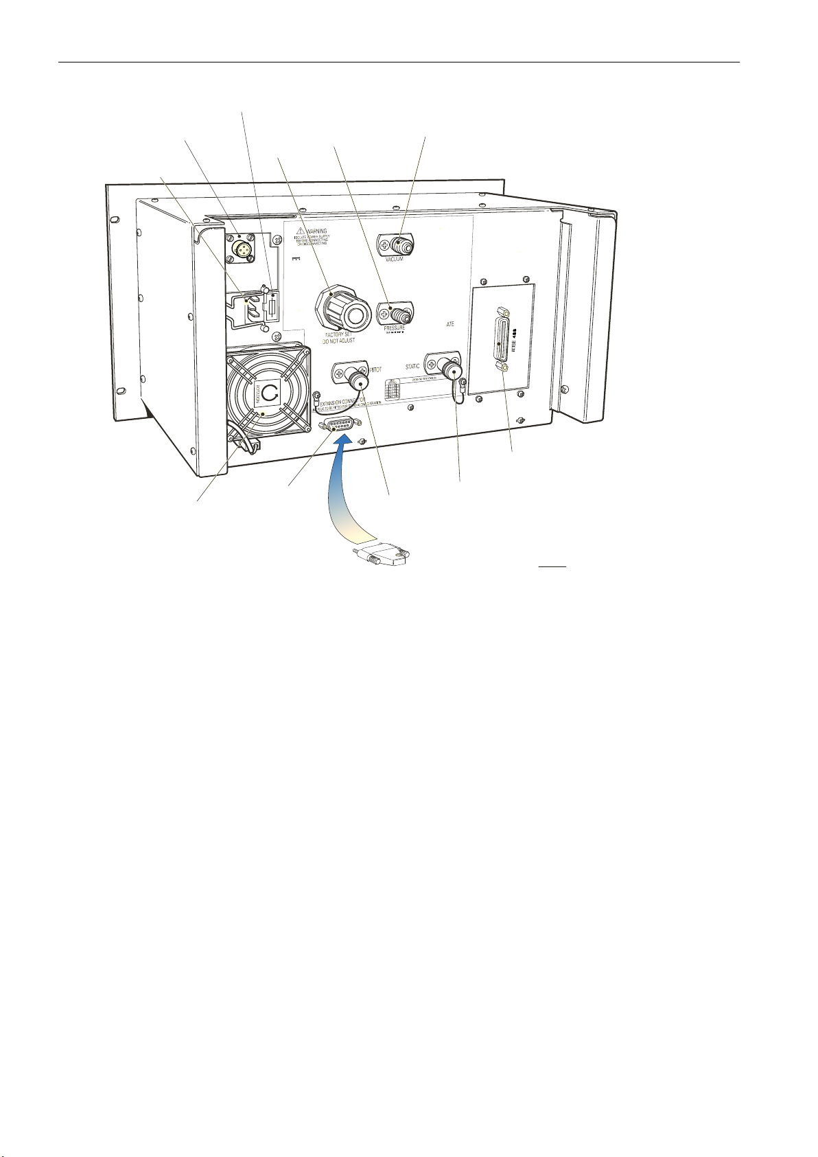
Chapter 2. INSTALLATION
AC fuses holder
DC power supply
Connector (option)
AC power supply
connector
Pressure
regulator
Source Pressure
Input connector
DC
INPUT
24-30V
400VA
AC
~
INPUT
100/120/230V~50/60Hz
115V~400Hz
400VA
FUSED2x
T5A250VHRC
Source Vacuum
Input connector
Cooling fan
air intake
Expansion port
(used with GE
PV103R pump unit)
Figure 2-5: ADTS 405R Rear Panel
Pitot
output
connector
IEEE 488
interface
Static
output
connector
Note:
When port not used with other equipment
the Expansion Port Plug
connector
MUST
be fitted.
12 | ADTS 405 Mk2 Instruction Manual-English © 2015 General Electric Company – All rights reserved.
Page 31

Positioning of the ADTS
ADTS HAND TERMINAL
Cover plate
for option
Remote
hand terminal
Connector cable
(2m or 18m)
Key-pad
and display
Solenoid
valve status
indicator
System
status
indicator
Elapsed
time
indicator
Pump
switch
Calibration
enable
switch
Altimeter
encoder
connector
Static
output
connector
Pitot
output
connector
Altitude sensor
datum height
Power
supply
switch
(optional)
Figure 2-6: ADTS 405F General View
Fan
outlet
cover
POWERSUPPLY24-30V
FUSES
T20A
POWERSUPPLY
100/120/230V~50/60Hz500VA
115~400Hz500VA
FUSES
T5.0A250VHRC
Pressure
input
connector
DC power
Supply fuses
500VA
T32A
AC power
Supply fuses
DC power
supply
connector
(optional)
Cross bonding
connector
AC power
supply
connector
Vacuum
input
connector
Auxiliary
Vacuum
output
connector
© 2015 General Electric Company – All rights reserved. ADTS 405 Mk2 Instruction Manual-English | 13
Page 32

Chapter 2. INSTALLATION
14 | ADTS 405 Mk2 Instruction Manual-English © 2015 General Electric Company – All rights reserved.
Page 33

Preparation
3. OPERATION
WARNING OBSERVE SAFETY PRECAUTIONS STATED IN LOCAL ORDERS AND THE
AIRCRAFT OR EQUIPMENT SERVICING PROCEDURES.
Make sure the electrical and pneumatic connectors, electrical cables, pipes and positioning of the
ADTS 405 comply with the instructions in this manual and local regulatory requirements.
3.1 Preparation
WARNING THE ELECTRICAL SUPPLY MUST INCLUDE A CONNECTION TO A PROTECTIVE
EARTH. SEE SAFETY AND INSTALLATION GUIDE 124M8686 FOR START-UP SAFETY CHECKS
AND INFORMATION.
Carry out the following before use:
a. If necessary, carry out the maintenance detailed in Section 4.3 “Maintenance Tasks”.
b. Make sure the air data test system power supply switch on the front panel is set to OFF.
c. Connect the air data test system to the electrical supply.
d. Inspect the pneumatic hoses for damage, ingress of dirt and moisture. Make sure the
aircraft adapters are serviceable.
3.2 Start-up
Before use, the ADTS 405 should be tested. Review and become familiar with the overall operating
states and test procedures before starting any test process on an aircraft or component.
3.2.1 Connections
a. Connect the hoses for the test procedures to the air data test system:
• Red hose to the STATIC output (Ps)
• Blue hose to the PITOT output (Pt)
b. Temporarily seal the free ends of the hoses.
Note: When connected take care not to restrict air flow to the hoses.
c. Connect the hand terminal to the air data test system through the hand terminal
connector on the front panel. If necessary, connect the hand terminal through the
extension cable.
© 2015 General Electric Company – All rights reserved. ADTS 405 Mk2 Instruction Manual-English | 15
Page 34

Chapter 3. OPERATION
3.2.2 Power-up
a. Check the power indicator is illuminated and set the front panel power switch to
OPERATE.
b. The display will show the following sequence:
1. Power-up screen.
2. ADTS 405 power-up screen.
3. Date of the last calibration and type of main transducer fitted.
4. Self-test message.
5. Measuring ground pressure message.
6. Equalizing system pressures message.
7. Display shows Leak Measure mode and the number of parameters last selected in
configuration.
i. The display, on the front panel or
hand-terminal, shows:
SYSTEM STATUS
DK425 V.xx
Display Power Up
Please Wait
Note: V.xx will display the current software version number.
ii. After a short time the display
shows:
SYSTEM STATUS
DRUCK
ADTS 405
DK415
VER.xx
RED - FAULT
ORANGE - NOT READY
Last Calibration
dd/mm/yy (dmy)
RPT Transducer
PLEASE WAIT
iii. Date format can be set to a leading value of day or month in SETUP.
16 | ADTS 405 Mk2 Instruction Manual-English © 2015 General Electric Company – All rights reserved.
Page 35

Start-up
iv. Self test and front panel LED status:
SYSTEM STATUS
Self Test
PLEASE WAIT
GREEN - READY
v. The system opens the zero valves and after approximately 7 seconds the valves
close and the routine continues. The display shows:
Measuring Ground
Pressures
PLEASE WAIT
vi. The system opens the output valves, Ps and Pt port pressures will safely remain at
the original measured values:
Equalising System
Pressures
(Valves May Pulse)
PLEASE WAIT
vii. At power on check the hand-held terminal display.
ALT 0 ft
Leak Measure
CAS 0 kts
Leak Measure WARMUP
The ADTS 405 system may now be used but for full specification accuracy and stability, wait the
“WARMUP” period of 15 minutes. The display shows “WARMUP” in the lower right hand corner, this
message clears automatically after the time period.
Note:
(1)The ADTS 405 is a continuous, self-monitoring system. If the system detects an
error, the display shows an error message. Lists of errors are detailed in Section 5,
Fault Finding and Testing.
(2) The display at power-up can be changed, see CONFIGuration (Pg. 3-27).
© 2015 General Electric Company – All rights reserved. ADTS 405 Mk2 Instruction Manual-English | 17
Page 36

Chapter 3. OPERATION
3.2.3 Units of Measure
When operating, in either pressure measure or pressure control modes, the ADTS 405 can display
the following unit information:
Table 3-1: Units of Measure
Aeronautical Functions
Altitude ALT ft, m
Calibrated and True Airspeed CAS, TAS kts, km/h, mph
Mach MACH Rate of Climb ROC ft/m, m/m, m/s, hm/m
Rate of Airspeed Rt CAS, kts/m, km/h/m, mph/m
Rate of Mach RtMCH Mach/m
Display
Abbreviation
Displayed Units
(if applicable)
Pressure Functions
Static (Absolute) Ps [P]
Pitot (Absolute) Pt [P]
Dynamic or Impact (Differential) Qc [P]
Engine Pressure Ratio EPR Rate of Ps Rt Ps [P]/m
Rate of Pt RtPt [P]/m
Rate of Qc Rt Qc [P]/m
Rate of EPR Rt EPR EPR/m
Where [P] is the currently selected pressure units from the following list:
mbar, inHg, mmHg, inH2O (4°C), inH2O (20°C), psi, hPa, kPa, inH2O (60°F), kg/cm2,%FS
Display
Abbreviation
Displayed Units
(if applicable)
Figure 3-1: Front Panel
18 | ADTS 405 Mk2 Instruction Manual-English © 2015 General Electric Company – All rights reserved.
Page 37

Operation quick reference
3.3 Operation quick reference
The quick reference chart shows normal operation key functions. See Section 6. ‘Reference and
Specification’ for detailed descriptions of ADTS 405Mk2 functions.
In the key/selection column the following applies:
ALT - Key.
[NEXT] - Item in menu (soft key).
(SINGLE DOUBLE) - Sequence of parameters selected by NEXT key.
(craft1 craft2...) - Sequence of names selected by NEXT key.
data entry - Enter number from key-pad.
The display shows the main pressure display (Leak Measure or Control mode).
Key/selection Function and comments
F1-F4
ALT Ps
SPEED Qc
MACH Pt
EPR
ROC Ps RATE
RATE TIMER
F1
F2
F3
HOLD
RATE
LEAK MEASURE/CONTROL
GROUND
[GO TO GROUND]
[DISPLAY QFE]
[DISPLAY QNH]
PORT
REMOTE
PRINT
[ALPHA]
[BACK]
data entry
EXECUTE TEST PROGRAM
[NEXT]
[PREV]
[RUN]
F1
F2
HELP
SETUP
See QUICK REFERENCE SETUP or MINIMUM SETUP
SETUP + F1
See QUICK REFERENCE -
CONFIG
(nudge up)
(nudge down)
0-9
-000
CLEAR/QUIT
ENTER
CLEAR/QUIT + ENTER
Function keys for menus
Altitude (Aeronautical units) or Ps (Pressure units)
Airspeed (Aeronautical units) or Qc (Pressure units)
Mach (Aeronautical units) or Pt (Pressure units)
Engine Pressure Ratio (pressure units only)
Rate of Climb (Aeronautical units) or Rate of Ps (Pressure units)
Start timing rate of change
Wait and time choice 1
Wait and time choice 2
Wait and time choice 3
Hold pressure at present value - Press again to release
Rate of change of Pitot parameter - Press Pitot parameter then RATE
Switches between measure mode (for leak testing) and control mode
Controls Ps to atmospheric pressure and Qc to zero at current rates of change
Display local atmospheric (ground) pressure
Display sea level equivalent of local atmospheric pressure
See Line Switching Unit User Manual
Switches (toggles) between remote and local operation
Prints current parameter values to a stored text file
Inserts alphabet character in user text
Deletes last character of user text
Numeric entry for user text
Execute down-loaded Test Programs
Select next listed test program
Select previous listed test program
Execute selected test program
Execute all tests in the test program
Selects and executes a specific test program
Press HELP then other key for further information
Temporary set-up - lost at power down
Configuration - changes power-up defaults
Hold F1 while pressing SETUP - then enter PIN
Increases aim value
Decreases aim value
Number entry
Minus sign for first number entry 000 (thousand) if not first number of entry
Clear number entry - quit from menu or clear warning message
Complete number entry
ABORT - restart with power-up
© 2015 General Electric Company – All rights reserved. ADTS 405 Mk2 Instruction Manual-English | 19
Page 38

Chapter 3. OPERATION
3.4 Operating modes
CAUTION Once initialised wait 15 minutes to allow the pressure measurement system
to reach a stable operating temperature. The “Warm-up” period can be reduced to 5
minutes if the system has been powered following a short period of inactivity.
The air data test system can now be set for a variety of functions and modes that follow:
1. Pressure measurement mode
2. Pressure control mode
3. Timed leak rate measurement
4. Control to local ground pressure
The ADTS 405 always powers-up in Measure mode with the pressure controllers off. When
changing to Control Mode the pump unit must be switched on and producing the correct pressure
and vacuum.
Each operating function shows the required key presses to set displays and selections.
Measure Mode (Pressure measurement mode)
To select the measured parameter press:
STATIC
ALT SPEED MACH
Ps Qc Pt
Measured
parameter
or or
Measured value Units of measurement
Alt 10000
Leak Measure
CAS 350 kts
“leak-measure” when
measure mode selected
Change display single,
dual or triple press:
Leak Measure
PITOT
ft
Change units from
aeronautical to pressure:
SETUP
[MORE]
[CONTROL]
[Ps Pt DUAL]
[DISPLAYS/OPTIONS]
[DISPLAY TYPE]
[OPTIONS]
20 | ADTS 405 Mk2 Instruction Manual-English © 2015 General Electric Company – All rights reserved.
SETUP
[UNITS]
[NEXT]
[PREV]
[SAVE]
Page 39

Control Mode (Pressure control mode)
For ADTS 405F set the pump switch to PUMP ON
PUMP ON
PUM
From leak measure press:
Operating modes
Alt
Leak Measure
Return to leak measure at new altitude
0
LEAK
MEASURE
CONTROL
ft
Aim of 5000 ft press
LEAK
MEASURE
CONTROL
5
Alt
Aim
Alt
Leak Measure
5000
5000 <
5000
Alt
Aim 0<
000
ft
ft
0
ft
ENTER
© 2015 General Electric Company – All rights reserved. ADTS 405 Mk2 Instruction Manual-English | 21
Page 40

Chapter 3. OPERATION
Leak measure mode (Timed average leak rate measurement)
Static channel altitude 5000 ft,
measure leak:
Set rate timer:
wait 05.00 miutes
test 01.00 minutes
RATE
TIMER
Alt
Leak Measure
Display shows alternating time
countdown and TIMING message
WAIT
F1 00:00
F2 00:00
F3 05:00
4996
00:30/TIMING
Alt
Leak Measure
TIME
00:30
01:00
01:00
ft
ROC
RtCAS
-15.00T
-1.97T
5000
Display shows alternating wait time
countdown and WAITING message
ft
Alt
Leak Measure
ft/m
kts/m
4996
04:36/WAITING
Display
rate timer
ft
shows
result
Timed Rates
Note: Compressing a gas generates heat. Gas heated or cooled in an enclosed
volume causes a pressure change. It is important, especially for leak testing, to
allow enough time for the heated gas to cool and the pressure to stabilize.
When setting the rate timer consider three factors:
1. The volume of the system to be tested (large volumes take longer to stabilize).
2. The pressure change (the higher the change the greater heat generated).
3. The ambient air temperature.
22 | ADTS 405 Mk2 Instruction Manual-English © 2015 General Electric Company – All rights reserved.
Page 41

Go to Ground (Control to local ground pressure)
Operating modes
Alt
Leak Measure
CAS 350
Leak Measure
Dual parameter display
Aim Ground <
CAS = 350.0
Aim 0.0
5000
Alt
Aim Ground <
CAS = 0.0
Aim 0.0 kts
120 ft
kts
ft
kts
(USER MODE)
GO TO GROUND
F1
F2
DISPLAY QFE
F3
DISPLAY QNH
LEAK
MEASURE
CONTROL
GROUND
Alt
5000 <ft
ft
Leak Measure
Single parameter display
Note:
In leakMeasure use F2 and F3 for
QFE and QNH information.
F1 invalid in this mode.
Alt
5000
Aim Ground <
Alt
Aim
120 <
Ground
ft
Checking Ground
PLEASE WAIT
Equalising System
Pressures
(Valves May Pulse)
PLEASE WAIT
Safe At Ground
Press CLEAR/QUIT
to continue..
Note:
This ground value will not be
zero and depends on local
atmospheric pressures and
aireld altitude.
Note:
Safe to disconnect pipes and adaptors
from the aircraft or component under test.
© 2015 General Electric Company – All rights reserved. ADTS 405 Mk2 Instruction Manual-English | 23
Page 42

Chapter 3. OPERATION
3.5 Operating Procedures
WARNING See Safety and Installation Guide 124M8686 for guidance on safety and
standard operating conditions.
The procedures show the steps required to make sure the ADTS 405 is serviceable and of the
settings required to test an aircraft system or component in the following notation:
1. All key presses are highlighted in bold and shown as identified on the key-pad.
2. Key presses inside brackets e.g., [MORE], are soft key presses (i.e, function key selections
{F1 to F4} indicated on the display screen).
For further information on a particular ADTS function and using the Help System refer to Section 6 Reference and Specification. The help information includes further details of the function and
details associated functions.
For a summary of Set-up and Configuration procedures refer to the quick reference charts, at the
end of this section.
3.5.1 Control or Measure Parameter
To change the (displayed) parameter:
a. Value parameters: Press the parameter key e.g, press SPEED/Qc to display airspeed.
b. Rate parameter: Press the associated parameter key followed by the rate key for that
channel. e.g, display airspeed rate, press SPEED/Qc then RATE. ROC/Ps Rate may be
directly pressed without first pressing ALT/Ps.
Note: The displayed parameters depend on the last keys pressed.
To display two parameters:
a. Press each value parameter in turn, e.g, display altitude and airspeed together, press ALT/
Ps then SPEED/Qc.
b. In control mode, an arrow, at the right-hand end of the aim value, indicates the last
parameter selected. This can be changed by entering a new value.
To display a value parameter together with its rate:
a. Press the parameter key followed by the associated rate key, e.g, display airspeed and rate
of speed together, press SPEED/Qc then RATE.
Note: If ROC/Ps Rate is pressed, the display automatically shows ALT and ROC.
See “SETUP RATE”, section 6.3, for display details.
Display Functions (Fig 3.2, Fig 3.3 and Fig 3.4)
The display normally shows pressures and rates or aeronautical equivalents. It can be set-up to
show, at the same time, one parameter (single), two parameters (dual) or three parameters (triple).
24 | ADTS 405 Mk2 Instruction Manual-English © 2015 General Electric Company – All rights reserved.
Page 43

Operating Procedures
The triple display always shows altitude and airspeed; with pressure units selected, the display
always shows Ps and either Qc, Pt or EPR. When ALT or CAS are selected the display shows the aim
and measured values of ALT and CAS as a dual display. With any other selected parameter the
display shows the measured values of altitude and airspeed and, the aim and measured value of the
other selected parameter. Additional display modes are available for certain options.
Note: The ADTS 405 automatically returns to the pressure display if left
inactive in any set-up or menu type display for a period of more than one
minute.
Controlled
or measured
parameter
Measured value
Alt
10000
Aim
Aim (set-point or target)
or “leak-measure” when
controller selected o
T for timed rate
of change
10000
Pointer for
parameter
Figure 3-2: Single Display
Measured values T for timed rate
of change
Units of
measurement
ft
WARMUP
Special
messages
Controlled
or measured
parameters
Alt
Aim
CAS
Aim
Aim (set-point or target)
or “leak-measure” when
controller selected o
10000
10000
582.0
600.0
Pointer for primary
parameter - aim that
changes on data entry
Figure 3-3: Dual Display
ft
Units of
measurement
kts
Special
message
© 2015 General Electric Company – All rights reserved. ADTS 405 Mk2 Instruction Manual-English | 25
Page 44

Chapter 3. OPERATION
Figure 3-4: Triple Display
Measured values T for timed rate
of change
Constant
indication
of values
Current
changing
parameter
Aim (set-point or target)
or “leak-measure” when
controller selected o
Alt
CAS
ROC
Aim
10000
582.0
2995
3000
Pointer for primary
parameter - aim that
changes on data entry
ft
kts
ft/min
Special
message
Units of
measurement
Rate Timer Displays (Fig 3.5 and Fig 3.6)
When in Leak Measure mode and, after completing a rate timing, the system generates the rate
timer displays. These displays are independent of the display mode (single, dual, triple or option).
Note: There is no pointer for the primary parameter, values cannot be entered
in the rate timer displays.
Pressing a parameter key (ALT, ROC, etc) or CLEAR/QUIT exits the rate timer displays.
Parameters
Measured
Timed
values
ROC
Rt CAS
-17.25 T
-0.52 T
T for timed rate
of change
ft/m
Kts/m
Timed Rates
Special
message
Figure 3-5: Rate Timer Display Aeronautical Units
Units of
measurement
26 | ADTS 405 Mk2 Instruction Manual-English © 2015 General Electric Company – All rights reserved.
Page 45

Operating Procedures
Parameters
Measured
Rt Ps
Rt Pt
Rt Qc
Timed
values
0.637 T
0.341 T
-0.224 T
T for timed rate
of change
mbar/m
mbar/m
mbar/m
Timed Rates
Special
message
Figure 3-6: Rate Timer Display Pressure Units
Pt Only Display (Fig 3.7)
The Pt only display overrides the other display modes (single, dual and triple). The measured
altitude and the CAS are produced from Ps in measure mode.
Alt always
shown
Measured
altitude
T for timed rate
of change
Units of
measurement
Alt
Selected
parameter
Pt Only
CAS
Aim
Aim (set-point or target)
or “leak-measure” if
Pitot controller selected o
3.5.1.1 Change display units:
a. Press SETUP.
b. Select [MORE].
c. Select [DISPLAYS/OPTIONS].
d. Select [DISPLAY TYPE].
407
0.0
0.0
Pointer for
parameter
Figure 3-7: Pt Only Display
ft
kts
Special
messages
e. Using [NEXT] or [PREV].
f. Select either SINGLE, DUAL or TRIPLE, ENCODER (more display types with options fitted).
g. Press [SAVE] to accept.
h. Press CLEAR/QUIT repeatedly to return to user display.
© 2015 General Electric Company – All rights reserved. ADTS 405 Mk2 Instruction Manual-English | 27
Page 46

Chapter 3. OPERATION
3.5.1.2 Change the display for Pt Only:
a. Press SETUP.
b. Select [MORE].
c. Select [Control], [Ps Pt Dual].
d. Select [Pt Only Mode].
e. Press CLEAR/QUIT repeatedly to return to user display.
3.5.1.3 Change measurement units:
In Full Set-up Mode any set of aeronautical or pressure units can be selected.
a. Press the SETUP key.
b. Select [UNITS].
c. Use [NEXT] and [PREV] keys to select the required units.
d. Select [SAVE] to accept.
e. Press CLEAR/QUIT repeatedly to return to the main pressure display.
• In Minimum Setup Mode only the default aeronautical and pressure units can be
selected.
• If Set-up Mode is switched off, units cannot be changed.
3.5.1.4 Change the unit type
a. Press the SETUP key.
b. Select [UNITS TYPE].
c. Select either [AERO] or [PRESS] to select the unit type.
d. Select [SAVE] to accept.
e. Press CLEAR/QUIT repeatedly to return to the main pressure display.
• The default pressure and aeronautical units are defined in the CONFIGuration
mode.
• Display cannot be changed with SETUP switched off or in minimum mode.
3.5.2 Aim
The ADTS 405 must be in control mode to set a new aim (current aim displayed). If the aim field
shows “Leak Measure” press LEAK MEASURE/CONTROL to enter control mode.
A new aim can be entered using the numeric keys. The existing aim is replaced when the first digit
of the new aim is pressed. Each digit is displayed as it is pressed, If an error is made during the entry
of data, press CLEAR/QUIT to restore the original aim.
Press ENTER to action the new aim.
Note: The 000 key can be used as a quick way of entering thousands.
28 | ADTS 405 Mk2 Instruction Manual-English © 2015 General Electric Company – All rights reserved.
Page 47

Operating Procedures
3.5.3 Leak Measure
a. Press LEAK MEASURE/CONTROL to return to Leak Measure mode.
b. Press RATE TIMER, F3 - [Wait 05:00, Time 01:00].
Note: Different wait and time periods can be selected by pressing F1 or F2.
c. Wait until rate timer has completed and the results displayed.
d. Check rate of climb is less than ±100 ft/min and rate of airspeed (CAS) is less than ±1 kt.
e. Press LEAK MEASURE/CONTROL to return to Control mode.
f. Press GROUND, F1, [Go to Ground].
g. Wait until for the display shows “Safe At Ground”.
3.5.3.1 ADTS 405 Leak Test
It is important to check that the ADTS 405 and the connecting equipment does not leak.
a. Before use a leak check should be carried out as follows:
b. Connect the pitot and static hoses (to front panel of ADTS 405F).
c. Temporarily seal the free ends of the hoses.
d. Set the display to dual display, see 3.9, Display.
e. Set the units to feet and knots, see 3.13, Changing the Units.
f. Using the SETUP menu, choose the limits set for the aircraft or UUT, see 3.14, Limit
Checking.
i. Press SETUP, [LIMITS], and [NEXT] until required wait is shown/set.
ii. Press [SEL] to save and then press CLEAR/QUIT until the main pressure screen
shown below is displayed.
ALT 125 ft
Leak Measure
CAS 0.0 kts
Leak Measure WARMUP
Note: The numeric value of the parameters displayed change with each powerup sequence. The amount of change depends on local atmospheric pressure
conditions at the time of power-up.
g. Press the LEAK MEASURE/CONTROL key to turn on the pressure controllers.
© 2015 General Electric Company – All rights reserved. ADTS 405 Mk2 Instruction Manual-English | 29
Page 48

Chapter 3. OPERATION
Example
To apply an altitude of 5000 ft at a rate of climb of 6000 ft/min and an airspeed of 300 kts at a rate
of 600 kts/min:
i. SPEED/Qc then RATE to select rate of change of speed.
ii. 6, 0, 0, ENTER to set the rate.
iii. SPEED/Qc to select airspeed.
iv. 3, 0, 0, ENTER to set an airspeed of 300 kts (airspeed [CAS] now starts increasing).
v. ROC/Ps Rate to select rate of climb.
vi. 6, 0, 0, 0, ENTER to set the rate of climb.
vii. ALT/Ps to select the altitude.
viii. 5, 0, 0, 0, ENTER to set altitude ([Alt] altitude now starts increasing).
ix. SPEED/Qc to view altitude and airspeed together.
Note: When altitude and airspeed are changing at the same time, and
automatic airspeed rate is enabled, the system automatically adjusts the
airspeed rate so that the aim points are reached at the same time. The airspeed
rate will not exceed the entered aim value.
Wait for the aim values to be achieved. Observe over a period of 1 minute that the value of Alt stays
within ±10 ft and the value of CAS with ±1 kt.
ALT 4050 ft
Aim 5000
CAS 289.0 kts
Aim 300.0 <
After a successful leak test, the ADTS 405 is ready to be connected to an aircraft system or unit
under test.
If the preliminary leak test is unsuccessful:
h. Leave the system to achieve thermal stability for a further five minutes, press CLEAR/
QUIT and repeat the leak test.
i. After another unsuccessful leak test:
j. Disconnect both hoses, check the condition of the o-rings on the Ps and Pt connectors as
detailed in the maintenance section and firmly replace the blanking caps.
k. Press CLEAR/QUIT and repeat the leak test procedure.
l. After a successful leak test without hoses connected:
m. Replace or repair the faulty hose(s) and re-test.
n. If the ADTS 405 fails the leak test without hoses connected, switch off and return the unit
to the repair depot.
Note: Compressing a gas generates heat. Gas heated or cooled in an enclosed
volume causes a pressure change. It is important, especially for leak testing, to
allow enough time for the heated gas to cool and the pressure to stabilize.
30 | ADTS 405 Mk2 Instruction Manual-English © 2015 General Electric Company – All rights reserved.
Page 49

Operating Procedures
3.5.4 Aircraft system protection
The ADTS 405 protects the aircraft system against user error and leaks in the aircraft system.
Note: The pumps must be switched on.
The system protection operates by:
• Limit checking of user entered set-points.
• Automatic regain of control if leak rate is over limit during leak testing.
• Automatic regain of control if a leak takes the system pressures outside of limits.
3.5.4.1 Auto recovery facilities
The pressure controllers in the ADTS 405 can “feed” a leak in an aircraft system. When first testing
an aircraft system, a leak test must be carried out at low altitude and airspeed.
• If, during a leak test, a leak in the system produces a rate of climb greater than the
rate set in limits or a rate of change of airspeed greater than the rate set in limits,
then the pressure controllers automatically regain control to minimise damage to
the aircraft system. This AUTO LEAK RECOVERY facility can be disabled.
• If a leak causes the system pressures to exceed any limit during a leak test, the
pressure controllers automatically regain control. This AUTO LIMIT RECOVERY
facility can be disabled.
• If negative airspeed (or Qc) occurs in measure mode, the zero valve is
automatically opened for one second to balance the airspeed. This only applies
when the minimum CAS (or Qc) limit is zero.
• Limits cannot be changed with SETUP switched off or Limit Lock enabled.
3.5.5 Limit Checking
The system checks all data entered against minimum and maximum limits set for the particular
limit set in use. If these limits are exceeded, the data entry is ignored and a warning message
displayed showing the minimum and maximum values that can be entered. The system also checks
all limits of associated parameters. If these limits are exceeded when a new value is entered, the
display shows the name of the associated parameter, e.g. If a Mach limit is exceeded when entering
an airspeed value the display shows “Mach” and the equivalent maximum and minimum limits as
airspeed values.
Similarly, if an ARINC 565 limit is exceeded when entering a value and ARINC limits are enabled, the
display shows `ARINC'.
3.5.5.1 Select the limits in use:
a. Press SETUP.
b. Select [LIMITS].
c. Use [NEXT] or [PREV] to select the limits required. Each set of limits is identified by its
name, including the pre-defined sets of limits (“Standard“, “Civil” and “Max” see section 1.3,
Operating Limits).
d. Select [SEL] to select the limits.
e. Press QUIT/CLEAR to return to the pressure display.
© 2015 General Electric Company – All rights reserved. ADTS 405 Mk2 Instruction Manual-English | 31
Page 50

Chapter 3. OPERATION
Table 3-2: Warning Messages
The following table lists the warning messages with the possible cause and action to be taken.
No. Message Probable Cause Action
2 INVALID USER
INPUT
3 OPERATE CAL
ENABLE ON
STATUS PANEL
4 ONLY VALID IN
CONTROL MODE
210 Ps SOFT START
TIMEOUT
212 Ps PRESSURE FAIL The Ps controller has detected loss of supply
213 Ps VACUUM FAIL The Ps controller has detected loss of supply
220 Pt SOFT START
TIMEOUT
222 Pt PRESSURE FAIL The Pt controller has detected loss of supply
223 Pt VACUUM FAIL The Pt controller has detected loss of supply
301 LEAK RATE TOO
HIGH REGAINING
CONTROL
302 OUTSIDE LIMITS
REGAINING
CONTROL
303 ZERO OFFSET TOO
LARGE
304 INITIALIZING
SYSTEM
305 OUTSIDE LIMIT GO
TO GROUND
306 SWITCH PUMPS ON Cannot select control mode with pumps off. Switch pumps on.
307 COMMUNICATION
RING FAULT-
PACKET IS
CORRUPT
308 UPDATING SYSTEM Software upgrade. Wait 1 minute.
309 CANNOT CONTROL Failed pump test. Check system limits.
310 PUMP TEST FAILED Pump not achieving limits. Set lower limits.
The numeric value entered was outside the
allowed range
Calibration started before removing calibration
enable plate on the front panel
Selection not allowed in Leak measure mode Select controller on.
The Ps controller has failed to go into control
mode
pressure and automatically switched all channels
to measure mode. This can occur at very high
rates of pressure change in large volume systems
if the pumps cannot produce enough pressure.
vacuum and automatically switched all channels
to measure mode. This can occur at very high
rates of pressure change in large volume systems
if the pumps cannot produce enough vacuum.
The Pt controller has failed to go into control
mode.
pressure and automatically switched all channels
to measure mode. This can occur at very high
rates of pressure change in large volume systems
if the pumps cannot produce enough pressure.
vacuum and automatically switched all channels
to measure mode. This can occur at very high
rates of pressure change in large volume systems
if the pumps cannot produce enough vacuum.
Control mode automatically regained for aircraft
safety as leak rates too high.
Control mode automatically regained for aircraft
safety as the measures values have drifted
outside the operating limits due to leaks.
The zero offset measured during auto-zero was
outside.
This only occurs on main system software
upgrade.
Measured pressure is outside new limits selected
or power-up limits.
Internal error. If the fault can be repeated, return to
Re-enter value within allowed range.
Refer to main fault finding chart in the
service manual.
Select CONTROL again. If fails again,
refer to main fault finding chart in the
service manual.
Restore pressure supply BEFORE going
to control mode again. Refer to main
fault finding chart in the service manual.
Restore vacuum supply BEFORE going to
control mode again. Refer to main fault
finding chart in the service manual
Select CONTROL again. If fails again,
refer to main fault finding chart in the
service manual.
Restore pressure supply BEFORE going
to control mode again. Refer to main
fault finding chart in the service manual.
Restore vacuum supply BEFORE going to
control mode again.
Correct leak and retest.
Correct leak and retest. If leak Ps,
ensure that normal Qc pressure is
applied (e.g. 200 kts to avoid negative
airspeed).
Return to maintenance depot for
calibration.
If message occurs during normal
operation, return to maintenance depot.
Control pressure to within limits.
maintenance depot.
32 | ADTS 405 Mk2 Instruction Manual-English © 2015 General Electric Company – All rights reserved.
Page 51

Operating Procedures
Using the CONFIGuration function, new sets of limits can be created and existing sets of limits can
be edited. In addition, the set of limits in use at power-up can be selected. If required, this selection
can be locked to prevent unauthorised changing of the limits.
Using the SETUP function, previously stored sets of limits can be recalled for use. Each set of limits
is stored under an aircraft name. Three pre-defined sets of limits “Standard“, “Civil” and “Max” limits
are supplied with the ADTS 405.
Note: The ADTS 405, when delivered, contains “Standard” and “Civil” limits; to
set and store “Max” limits, for the first time, enter configuration. The “Max”
limits depend on the range of the pitot channel either 850 or 1000 knots, see
section 1.3, Operating Limits.
3.5.6 Changing Parameters
3.5.6.1 Mach Test and Constant Mach
To go to 0.8 Mach, enter Control Mode and proceed as follows:
a. Press SPEED then RATE to select rate of change of airspeed.
b. Enter required rate, e.g. 300 kts/min.
c. Press MACH.
d. Enter 0.8.
e. Wait for the Mach to be achieved.
Note: If the altitude changes the system automatically adjusts the airspeed to
keep the Mach value constant.
3.5.6.2 True Airspeed
The normal airspeed parameter is Calibrated Airspeed (CAS) (equivalent to IAS for testing
purposes).
The airspeed parameter may be changed to True Airspeed (TAS) as follows:
a. Press SETUP then SPEED.
b. Select [CAS/TAS].
c. Select [TAS].
d. Press QUIT/CLEAR repeatedly to exit set-up.
e. Press SPEED.
The display now shows the airspeed parameter as TAS.
Note: Airspeed parameter type can only be changed in Full Set-up mode. Rate of
change of airspeed will still be shown as Rate CAS.
Pitot temperature (Θt) is used in the calculation of TAS. Pitot temperature can only be changed in
Full Set-up mode. To enter (Θt):
a. Press SETUP.
b. Press SPEED.
c. Select [Pt TEMPERATURE].
d. Enter the temperature measured by the aircraft's Pitot temperature sensor.
e. Press QUIT/CLEAR three times to return to user display.
© 2015 General Electric Company – All rights reserved. ADTS 405 Mk2 Instruction Manual-English | 33
Page 52

Chapter 3. OPERATION
3.5.6.3 Airspeed Switch test
The following example shows how an airspeed switch can be functionally checked.
Note: For low airspeed switches (i.e. 130 knots) the Pt Only facility could be used.
Example
a. Press LEAK MEASURE/CONTROL to enter control mode. Press SPEED/Qc.
b. If necessary, press RATE and enter a change of airspeed low enough to observe switch
operation.
c. Enter an Aim value below the operating limits of the switch (i.e., airspeed switch operating
at 130 knots ±2 knots set 127 knots).
d. Press ENTER and observe the airspeed changing.
e. Using the nudge facility, set to an appropriate step value, increase the Aim value.
f. Increase the Aim until the switch operates (contacts close) and record the value.
g. Change the Aim to above the airspeed operating range (i.e. 133 knots). Repeat the steps 3
to 5, decreasing the Aim value until the airspeed switch operates (contacts open) and
record value.
This procedure can be repeated. If many operations of a switch are required use the oscillating
facility detailed in Full Set-up, see 6.2.30. The above method (steps a. to g.) can be applied for the
other parameters:
Examples:
Altitude switch
• Low altitude warning
• Landing gear configuration warning
• Height lock
Mach switch
• Speed brake scheduling
• Mach cruise lock
3.5.7 Engine Pressure Ratio (EPR)
The ADTS 405 may be used to check EPR sensors and indicators. Use Ps for INLET pressure and Pt
for OUTLET pressure. To carry out an EPR check, the display
mbar or in Hg.
must be showing pressure units e.g,
3.5.7.1 Example EPR
To enter an EPR of 1.8 with inlet pressure of 500 mbar (15 inHg), proceed as follows:
a. If the display shows “Leak Measure”, press LEAK MEASURE/CONTROL to regain control.
Note: The pressure/vacuum pumps must be switched on.
b. Press ROC/Ps RATE to select rate of change of static.
c. Enter required rate of change e.g, 1000 mbar/min, (30 inHg/min).
34 | ADTS 405 Mk2 Instruction Manual-English © 2015 General Electric Company – All rights reserved.
Page 53

Testing Aircraft Systems or UUT
d. Press EPR then RATE to select EPR rate.
e. Enter required value e.g, 5 EPR/min and press ENTER.
f. Press ALT/Ps.
g. Enter 500 mbar (15 inHg) and press ENTER.
h. Press EPR.
a. An EPR of 1.8 will quickly be achieved.
Note: EPR testing can also be performed by specifying the actual INLET and
OUTLET values.
3.6 Testing Aircraft Systems or UUT
WARNING OBSERVE THE APPROPRIATE SAFETY INSTRUCTIONS AND PROCEDURES
DETAILED IN THE AIRCRAFT MAINTENANCE MANUALS OR COMPONENT MAINTENANCE
MANUALS.
a. Connect the applicable hoses and adapters to the aircraft system or UUT.
b. Do a leak test detailed in the appropriate aircraft or component manual, to make sure that
the connections to the aircraft system or UUT are not leaking.
3.6.1 Go To Ground and Shut-down
At the end of testing and, before disconnecting from the aircraft system or UUT, the pressures in
the system must be taken to the local atmospheric pressure (ground) with zero airspeed, as
follows:
a. If the display shows “Leak Measure”, press LEAK MEASURE/CONTROL.
b. Press GROUND, F1, [Go To Ground].
c. Wait for the display to show “Safe At Ground”.
d. It is now safe to disconnect the aircraft system or UUT.
The pressure in the system changes towards ground. The ground pressure or “Ground” replaces the
static or altitude aim value.
3.6.1.1 While Going to Ground
If required, new rates of change can be entered while going to ground.
• To change the ROC or static rate, press ROC/Ps Rate and enter the new value.
• To change the airspeed or Qc rate, press SPEED/Qc then RATE and enter the new
value.
© 2015 General Electric Company – All rights reserved. ADTS 405 Mk2 Instruction Manual-English | 35
Page 54

Chapter 3. OPERATION
3.6.1.2 To Change from Going to Ground
To change, enter a new altitude (static) or new airspeed (Qc) set-point.
a. When the airspeed reaches zero and the Ps channel pressure nears ground, the
system re-measures atmospheric pressure to update the recorded ground
pressure (QFE). During this period, the display shows the message “Checking
Ground”. The ADTS 405 then reconnects to the aircraft system and equalises the
system pressures. Commands cannot be entered when these two messages are
displayed.
The Ps channel pressure is then taken to the new recorded atmospheric pressure and, at this new
pressure, the display shows the message “Safe At Ground”. The ground vent and zero valves
remain open to keep the aircraft system vented to atmosphere.
b. Press CLEAR/QUIT to continue with normal operation. The ground vent and zero
valves automatically close.
3.6.2 SETUP and CONFIGuration options
The SETUP key provides access to secondary functions using a menu system, extends the keyboard
and allows many of the ADTS 405 functions to be customized. All changes made under SETUP are
temporary and will be lost when the system is switched off. The range of options allowed in set-up
is determined by the set-up mode.
Example
Press SETUP and the display shows:
F1 Units
SETUP
1. Pressing a function key (F1 to F4) enters the set-up menu.
2. When in set-up, pressing a key (ALT Ps in this example) enters a menu or setting that
applies to the parameter.
F2 Limits
F3 Oscillation
F4 More
ALT
Ps
Figure 3-8: Set-up example
Enter Height of
Instrument Above
ADTS
> 0
ft
36 | ADTS 405 Mk2 Instruction Manual-English © 2015 General Electric Company – All rights reserved.
Page 55

Testing Aircraft Systems or UUT
3.6.2.1 To change units in FULL SETUP Mode as follows:
a. Press SETUP.
b. Select [UNITS].
c. Select required pressure units for display using [NEXT], [PREV] and [SAVE].
d. Use CLEAR/QUIT to return to pressure display.
3.6.2.2 To change units in MINIMUM SETUP Mode as follows:
a. Press SETUP.
b. Select [UNITS TYPE].
c. Select [PRESS].
d. Use CLEAR/QUIT to return to the main pressure display.
Note: Pressure units cannot be selected when set-up mode is switched off.
Holding down the F1 key while pressing SETUP provides access to the CONFIGuration mode.
CONFIGuration is similar to SETUP with many identical functions. The changes made under
CONFIGuration are permanent and remain set after the system is switched off. Configuration can
be used to change the power-up default settings of the ADTS 405 functions:
a. Holding down F1 then pressing SETUP causes the system to enter CONFIGuration mode.
CONFIGuration may be password protected using a four digit PIN. If PIN protected, the
display prompts for entry of the PIN. Press each digit of the PIN in turn (ENTER is not
required) as each digit is entered, an asterisk appears. If an incorrect PIN is entered, the
complete PIN is requested again.
b. When the correct PIN is entered, the CONFIG menu appears.
c. The PIN may be changed using CONFIG,-000.
d. To use the configuration menu, press the appropriate function key to select the required
menu item. To configure a parameter key, enter configuration menu then press the
required parameter key. Each parameter key configuration provides changes to the normal
user mode function and to the settings available in the set-up menu.
e. Once a parameter has been changed in configuration, use CLEAR/QUIT to return to the
previous menu. After all required key parameters have been changed, repeatedly press
CLEAR/QUIT until the display shows the normal operating mode.
© 2015 General Electric Company – All rights reserved. ADTS 405 Mk2 Instruction Manual-English | 37
Page 56

Chapter 3. OPERATION
FULL SET-UP
Key/selection Function and comments
SETUP + KEY PRESS
PyppwixytwipigxihmrgsrƉkyvexmsr
[UNITS]
[NEXT]
[PREV]
[SAVE]
[LIMITS]
[NEXT]
[PREV]
[SEL]
[OSC]
[Ps]
[START]
[STOP]
[FREEZE]
[AMPL/FREQ]
[AMPL]
Data Entry
[FREQ]
Data Entry
[Pt]
[MORE]
[CONTROL]
[Ps Pt DUAL]
[DISPLAYS/OPTIONS]
[
DISPLAY TYPE]
[NEXT]
[PREV]
[SAVE]
[I/O SETUP]
[ENET SUPER]
[-]
[FIXED IP]
[ADDR]
[MASK]
[BCST]
[SHOW ACTIVE]
[ENET COMMS]
[-]
[-]
[SHOW ACTIVE]
[OPTIONS]
[CLOSE O/P VALVES]
[OPEN O/P VALVES]
[SYSTEM SELF TEST]
Select units
Step through available units
Step back though available units
Select displayed units
Select set of limits
(aircraft 1\aircraft 2 ...)
As NEXT, in reverse order
Select displayed limit set
Oscillate about aim
For Ps channel
As for Ps channel
Selects Ps only, Pt only or Dual channel control
Select single, dual or triple display
(SINGLE\DUAL\TRIPLE\ENCODER)
As NEXT, reverse order
Save displayed Display Type
Configure Ethernet
Supervisor node Ethernet parameters
Menu option not available. DHCP select in CONFIG only
Setup fixed IP Address
IP Address
Subnet Mask
Broadcast
Confirm active IP settings
Communications node Ethernet parameters
Menu option not available. DHCP select in CONFIG only
Menu option not available. Fixed IP select in CONFIG
only
Confirm active IP settings
See option manual
Close output val
Open output valves
Start self test
ves
38 | ADTS 405 Mk2 Instruction Manual-English © 2015 General Electric Company – All rights reserved.
Page 57

Testing Aircraft Systems or UUT
FULL SET-UP Continued
Key/selection Function and comments
SETUP contd...
SETUP + KEY PRESS
ALT
data entry
SPEED
[AUTO ZERO]
[ON]
[OFF]
[CAS/TAS]
[CAS]
[TAS]
[Pt TEMPERATURE]
data entry
MACH
[DEFAULT]
[OFF]
[ON]
RATE TIME
[WAIT/TIME ON F1]
[TIME]
[WAIT] Change to WAIT
data entry
data entry
[WAIT TIME F2]
RATE
[ON]
[OFF] Manual
LEAK MEASURE
[AUTO LEAK]
[ON]
[OFF]
[AUTO LIMIT]
[ON]
[OFF]
GROUND
data entry
PORT
REMOTE Remote mode lock, see conƉguration
Full or minimum set-up selected in conƉguration.
Altitude correction value
Auto zero function
Temperature for true airspeed
Enter Pitot temperature
Mach limit
DeƉrihfy current limits
Removes Mach limit
OrefpiwWeglpmqmt
Enter new Mach limit data entry
Set-up WAIT and TIME time periods
For F1
Change to TIME
of TIME time
of WAIT time
See [Wait/Time on F1]
See [Wait/Time on F1] [WAIT TIME F3]
Automatic airspeed rate
Automatic
A
uto leak recovery on or oƇ
Auto limit recovery on or oƇ
See Line Switching Unit User Manual
© 2015 General Electric Company – All rights reserved. ADTS 405 Mk2 Instruction Manual-English | 39
Page 58

Chapter 3. OPERATION
FULL SET-UP and MINIMUM SET-UP
SETUP contd...
PRINT
[DATE/TIME]
data entry
[TIME]
data entry
HELP
[NEXT]
data entry
[PREV] As NEXT, in reverse order
data entry
d (Nyhke DOWN)
Full set-up selected in conƉkuration.
Adjust date and time
Enter Date [DATE]
Enter Time
Help on SETUP
Enter nudke valuesc (Nyhke UP)
(ALT \ CAS / TAS \ MACH \ ROC \ RATE \ RATE CAS)
Aeronautical units or
(Ps \ Pt \ Qc \ EPR \ RATE Ps \ RATE Qc \ RATE EPR)
Pressure units
Requirehryhkimrgrement
As Nudke UP
MINIMUM SET-UP
Key/selection
SETUP
[UNITS TYPE] Set units type
[AERO] Set units to default aeronautical units
[PRESS]
[LIMITS]
[NEXT]
[PREV]
[SEL]
AL
T
data entry
PORT
HELP
EXECUTE TEST PROGRAM
[PRINT]
[PRINT FILE] Print result Ɖle option
[NEXT]
[PREV]
[PRN]
Function and comments
Minimum set-up selected in conƉkuration.
Set units to default pressure units
Select set of limits
(aircraft 1\aircraft 2...)
As NEXT, in reverse order
Select displayed limit set
Altitude correction value
See user manual K0157
Help on set-up
Result Ɖle related print option
Print/save mode selection [PRINT/SAVE]
Pvmrxkirirated result data
Sazikirirated result data to Ɖle [SAVE]
Select next result Ɖpe
Select previous result Ɖle
Print selected result Ɖle
40 | ADTS 405 Mk2 Instruction Manual-English © 2015 General Electric Company – All rights reserved.
Page 59

CONFIGURATION
Testing Aircraft Systems or UUT
Key/selection
C
ONFIG (SETUP + F1)
[UNITS] Default units
[AERONAUTICAL] Sele ct default aeronautical units
[PRESSURE] Select default pressure units
[TEMPERATURE] Select default temperature units
[LIMITS] MsrƉkyviwixw of limits
[EDIT LIMITS]
[NEXT]
[PREV]
[SAVE]
[NEXT]
[PREV]
[SAVE]
[C]
[EDIT EXISTING]
[NEXT]
[PREV]
[SEL]
Function and comments
Hold F1 and press SETUP to enter CONFIG.
Step through available units
Step back through available units
Save selected units
Step through available units
Step back through available units
Save selected units
°C
°F [F]
Change limit values
Change existing values
(aircraft 1 \ aircraft 2...)
As NEXT, in reverse order
Select aircraft to EDIT limits
NAME \ MAX ALT \ MIN ALT \ MAX CAS \ MIN CAS \ MAX
MACH \ MAX ROC \ MAX RATE
[NEXT]
[PREV] As NEXT in reverse order
[ON/OFF]
data entry
[ALPHA]
c
d
[BACK]
[MAX LIMITS]
[EDIT NEW]
[CLEAR LIMITS] Clear an existing set of limits
[NEXT]
[PREV]
[SEL] Clear selected limits
[YES]
[NO]
[LOCK AIRCRAFT]
[ON]
[OFF]
[DEFAULT AIRCRAFT]
[NEXT]
[PREV]
[SEL]
CAS \ MIN Ps \ MAX Ps \ MIN Qc \ MAX Qc \ MAX RATE Ps
\MAX RATE Qc \ ARINC
LIMITS \ AL
Switch (tog gle) to ARINC 565 limits
Limit value
Insert alphabet character in name
Nudge up select next letter in alphabet
Nudge down select
Delete last character in name
Create maximum limits called “MAX”
Create new limits. As for [EDIT EXISTING][SEL] above
(aircraft 1 \ aircraft 2...)
As NEXT, in reverse order
CsrƉvq delete
Only DEFAULT limits available in USER mode
SETUP can be used to select aircraft
(aircraft 1 \ aircraft 2...)
As NEXT, in reverse order
Select aircraft limits used at power-up. May be locked
TITUDE CORRECTION
previous letter in alphabet
© 2015 General Electric Company – All rights reserved. ADTS 405 Mk2 Instruction Manual-English | 41
Page 60

Chapter 3. OPERATION
CONFIGURATION Continued
CONFIG (SETUP + F1) contd...)
[MORE]
[CONTROL] Ps Pt DUAL control
[Ps Pt DUAL]
[DISPLAY/OPTIONS
[DISPLAY TYPE] Select single, dual or triple display
[PREV]
[SAVE] Save displayed Display Type
[ENET COMMS]
[OPTIONS] See option manual
[CLOSE O/P VALVES]
[OPEN O/P VALVES]
[SYSTEM SELF TEST]
[DATE FORMAT]
[DMY]
[SETUP MODE]
[OFF]
[MIN]
[FULL]
Hold F1 and press SETUP to enter CONFIG.
Ps single pipe testing of altimeters. Pt single pipe
testing of airspeed and Mach indicators. DUAL normal
combined system testing.
(SINGLE/DUAL/TRIPLE/ENCODER) [NEXT]
as NEXT, in reverse order
MsrƉkyvi Ethernet [I/O SETUP]
Supervisor node Ethernet parameters [ENET SUPER]
[DHC] Network Allocated IP
[FIXED IP] ]ixytƉ|ihSZKhdress
[ADDR]
[MASK]
[BCST]
[SHOW ACTIVE]
[FIXED IP] ]ixytƉ|ihSZKhdress
[ADDR]
[MASK]
[BCST]
IP Address
Subnet Mask
Broadcast
CsrƉvqegxmziSZwixxmrks
Communications node Ethernet parameters
Network Allocated IP [DHCP]
]ixytƉ|ihSZKhdress
Subnet Mask
Broadcast
CorƉvq active IP settings [SHOW ACTIVE]
Close output valves
Open output valves
Start self test
Format of daxixi|t
UK format DD/MM/YY
US format MM/DD/YY [MDY]
Limits acce
ss to set-up functions
42 | ADTS 405 Mk2 Instruction Manual-English © 2015 General Electric Company – All rights reserved.
Page 61

Testing Aircraft Systems or UUT
CONFIGURATION Continued 2
CONFIG (SETUP + F1) + KEY PRESS Hold F1 and press SETUP to enter CONFIG.
[SPEED] Auto zero function
[AUTO ZERO]
[ON]
[OFF]
[CAS/TAS] ConƉgu
[CAS]
[TAS]
[Pt TEMPER-ATURE]
data entry
ConƉgure Pt temperature
re calibrated or true airspeed
RATE TIME
[WAIT/TIME ON F1] For F1
[WAIT]
data entry
data entry
[WAIT/TIME ON F2]
RATE Automatic airspeed rate
[OFF] Manual
LEAK MEASURE
[AUTO LEAK ON
[ON]
[OFF]
[AUTO LEAK LOCK
[ON]
[OFF]
[ON]
[OFF]
[AUTO LIMIT LOCK] Lock auto limit recovery state
[ON]
[OFF]
/OFF]
]
FF]
ConƉgure WAIT and TIME times
Change to TIME [TIME]
Change to WAIT
TIME time period
WAIT time period)
See Wait/Time on F1
See Wait/Time on F1 [WAIT/TIME ON F3]
Automatic [ON]
Auto leak recovery lock
Lock auto leak recovery lock
Auto leak recovery state [AUTO LIMIT ON/O
© 2015 General Electric Company – All rights reserved. ADTS 405 Mk2 Instruction Manual-English | 43
Page 62

Chapter 3. OPERATION
CONFIGURATION Continued 3
CONFIG (SETUP + F1) + KEY PRESS
contd...
GROUND
dexeirxvy
PORT
REMOTE
[ON]
[OFF]
ETP
AUTO RUN
[NEXT]
[PREV]
[NONE]
[SEL]
ERASE PROGRAMS
[NEXT]
[PREV]
[DEL]
RESULTS
[PRINT/SAVE]
[PRINT] Girivetihviwypx dexetvmrxid
[SAVE]
[ERASE FILE]
[NEXT]
[PREV]
Xyhki yt ( c )
[DEL] Dipixi wipigxi
RophP:erhtriww]O^_Zxs irxir CONFIG.
AivƉiphepxmxyhijsv[XRhmwtpey
\ijir to stxmon ywiv meryep
Rimoti mshi psck
Ryr xiwx tvskveq on ts{ivyt
Rijivxs stxmsr ywivqeryep
Dipixi xiwxtvskvem
Zvmrx-]eziqshiwipigxmsn
Qirivexihviwypx dexewezihmreƉpi
RiwypxƉpihhipixistxmsn
]ipigxri|xviwypxƉpi
]ipigx tvizioyw viwypt Ɖpi
d viwypx Ɖpi
[NEXT]
[PREV] ewXOb^mrvizivwisvhir
hexeirxry
Xyhki do{n ( d )
[000]
dexeirxvy
ALT\CAS/TAS\MACR\ROC\RATE
CAS\Pw\Pt\[c\EPR\RATE Pw.RATE [c\RATE EPR)
Riuymvihryhkimrgviqirt
Kw nydki yt
PIN tvsxiction
PIN (cshi ryqfiv to irxiv CONFIG) wix to 0000 jsv “no
gshiviuymvih”
44 | ADTS 405 Mk2 Instruction Manual-English © 2015 General Electric Company – All rights reserved.
Page 63

Communications panel options
3.7 Communications panel options
3.7.1 Ethernet System
The ADTS405 is equipped with a TCP/IP Ethernet interface, and appears on the network as up to
two separate IP addresses. The first IP address relates to the ADTS instrument supervisor and
contains access to the functions described above. The second address relates to the
communications adapter (if fitted). There are no user related functions accessible within the
communications adapter IP port at this time, however the functionality of the port may be assessed
and tested if required.
The system is supplied with factory default IP addresses as follows:
192.168.2.2 Supervisor
192.168.2.3 Communications Adapter
The ports are most simply tested using a network ‘ping’ to these addresses.
Connect the ADTS to a computer equipped with a network interface, using a UTP network cable.
The network interface should be configured with an IP address on the same subnet.
Example:
If the ADTS has the default IP addresses then the host network address should be configured as
192.168.2.1/255.255.255. The method for doing this may vary but the following example screens
show the method under Windows 7. It is suggested to take careful note of the original computer
settings so they may be restored after the check.
Figure 3-9: Configuring Windows For ADTS Subnet IP Address
A ping to either of the above ADTS IP addresses should give the following typical response seen in
figure 3-10 Ping Test from Windows Command Prompt below:
© 2015 General Electric Company – All rights reserved. ADTS 405 Mk2 Instruction Manual-English | 45
Page 64

Chapter 3. OPERATION
Figure 3-10: Ping Test From Windows Command Prompt
The IP address settings may be changed to match local network requirements using the
CONFIGuration and SETUP menus, as described in section 3.6.2.
An SSH server is available on each IP address for general purpose file access. The factory default
user name and password for accessing the server is:
User Name adts
Password druk
It is strongly advised that the default password be changed as part of the initial end user
customisation.
3.7.1.1 Changing the Default Access Password
Configure the network interface with an IP address on the same subnet (as described above). Open
an SSH client program. If using a PC then a third party client such as PuTTY may be used.
Example
a. Open the Configuration screen.
b. Enter the supervisor IP address and select the SSH as the required connection type, see
figure 3-11, PuTTY Configuration.
Figure 3-11: PuTTY Configuration
46 | ADTS 405 Mk2 Instruction Manual-English © 2015 General Electric Company – All rights reserved.
Page 65

Communications panel options
c. Press “OPEN” and select “YES” to any security warnings.
d. Enter the user name “adts” and the default or current password when prompted.
e. At the $ prompt, enter command <passwd> followed by the <RETURN> key.
f. Follow the screen prompts by Enter the existing password followed by the new password
and further confirmation entry. The results of a successful change should look like the
PuTTY window in figure 5-7 below:
Figure 3-12: Changing the default password
g. Close the PuTTY window and confirm that a new connection can still be gained using the
new password.
3.7.2 Access ADTS files
Working with the filing system is best done using a window based FTP client that also supports SSH,
such as Win SCP. The following example sequence shows how access is gained and what file
directories are visible.
a. Open Win SCP and create an SFTP login using the following credentials and save under a
suitable name for future connections:
Host Name: 192.168.2.2 (being the IP address for the motherboard)
Port: 22
User name: adts
Password: druk
Private key: (leave blank)
b. Connect to the unit by pressing “Login”.
Figure 3-13: WinSCP Login Screen
© 2015 General Electric Company – All rights reserved. ADTS 405 Mk2 Instruction Manual-English | 47
Page 66

Chapter 3. OPERATION
c. The ADTS 405F file system directories (under folder fs\etfs) are visible in the right hand
pane as shown in figure 3-14 File system directories screen below:
Figure 3-14: ADTS File System Directories Screen
The example ETP (Test Programs) directory can be seen to contain two default test programs,
“altosc” and “asposc”, used for oscillation of altitude and airspeed. New prepared programs may be
added from the PC left panes by drag and drop to the ETP directory. They will then become available
for stand-alone use under the front panel ETP key. Unwanted programs may be deleted from the
ETP directory as required.
Similarly, any reports previously generated using the “PRINT” key will be available under the
“SPOOL” directory. This may be transfer to the PC window for archive or hard copy print as required.
d. The access session can now be closed using the Win SCP “Session” tab > Disconnect.
3.7.3 Connection of the IEEE 488 Facility
CAUTION THE OPTION CONNECTOR COVER MUST ALWAYS BE FITTED WHEN THE
EQUIPMENT IS USED OUTDOORS OR IN AN ENVIRONMENT WHERE MOISTURE MAY ENTER
THE UNIT THROUGH THE OPTION CONNECTOR PANEL.
To enable and disable this IEEE 488 facility access the configuration menu. When enabled,
this facility will be available from power-up of the ADTS 405 with the settings held in nonvolatile memory.
The IEEE 488 connector is located behind the (optional) communications module cover plate and is
configured as detailed in Table 3-2 IEEE 488 facility below.
48 | ADTS 405 Mk2 Instruction Manual-English © 2015 General Electric Company – All rights reserved.
Page 67

Enabling the Altimeter Encoder Option
Table 3-3: IEEE 488 facility
Standard
connector pin
number
1 D101 13 D105
2 D102 14 D016
3 D103 15 D107
4 D104 16 D108
5 E01 17 REN
6 DAV 18 Gnd [2]
7 NRFD 19 Gnd [2]
8 NDAC 20 Gnd [2]
9 IFC 21 Gnd [2]
10 SRQ 22 Gnd [2]
11 ATN 23 Gnd [2]
12 Shield [1] 24 Gnd [2]
Function
[1] Chassis connection
[2] 0V return for signals (not chassis)
Standard
connector pin
number
Function
3.7.3.1 Enabling the IEEE 488 Facility
To enable the IEEE 488, set the ADTS 405 to the SCPI IEEE option and set to Address 1 as follows:
a. Press and hold down F1 then press SETUP to enter the configuration menu. Release both
keys.
b. If requested, enter PIN details.
c. Press [MORE], [DISPLAY/OPTIONS], [OPTIONS], [IEEE-488], [SCPI/OPT2].
d. Check the display shows that SCPI is selected, if the settings are correct, press CLEAR/
QUIT until the display shows the main pressure display.
3.8 Enabling the Altimeter Encoder Option
a. Press and hold down F1 and press SETUP to enter the configuration menu. Release both
keys.
b. Press [MORE], [DISPLAY/OPTIONS], [DISPLAY TYPE], [NEXT], [ENCODER].
c. Check the display shows “Encoder” is selected.
d. Press [SAVE], then repeatedly press CLEAR/QUIT until the display shows the following:
Note: With an incorrect bit combination such as all zeros, the display shows
“ENCODER ERROR” in the place of the decoded value.
© 2015 General Electric Company – All rights reserved. ADTS 405 Mk2 Instruction Manual-English | 49
Page 68

Chapter 3. OPERATION
50 | ADTS 405 Mk2 Instruction Manual-English © 2015 General Electric Company – All rights reserved.
Page 69

Introduction
4. MAINTENANCE
4.1 Introduction
This section details the recommended maintenance tasks to be carried out by the operator. The
maintenance chart shows the periodicity of each task and a code referenced to the task detailed in
4.3 Maintenance Tasks.
Table 4-1: Maintenance Chart
Task Code Period
Inspect A Daily, before use
Inspect B Weekly
Test C Before use
Test D Daily, before use
Calibrate E Every 12 months *
Replace F
Clean G Weekly *
Service H
Service J
As detailed in fault finding or when detailed after
inspection
1,000 hours recorded by the pump unit elapsed time
indicator or the equipment running log
3,000 hours recorded by the pump unit elapsed time
indicator or the equipment running log
* Periodicity may change depending on usage and environment, refer to the
Engineering Authority.
4.2 Materials
This lists materials required for the user to maintain the ADTS 405. The item number and name in
the table identifies the item in the maintenance tasks (for example, “Use a soft bristle brush, item 4,
Table 4-2”). The description provides further information required to identify the item.
Table 4-2: Materials List
Item
Number
1 Cloth, Cotton, Lint-free
Alcohol, Isopropyl (MIL-A-10428,
2
Grade A)
3 Detergent, Mild, liquid
4 Brush, soft bristle (MIL-B-43871)
Note: Equivalent substitutes can be used.
Item Name, Description
© 2015 General Electric Company – All rights reserved. ADTS 405 Mk2 Instruction Manual-English | 51
Page 70

Chapter 4. MAINTENANCE
Table 4-3: Tool and Test Equipment Requirements
(1)
Ref Code
1 Multimeter, Digital Fluke 87V
2 Insulation tester, 500V Fluke1507
(2)
Nomenclature
(3)
Example Manufacturer’s
part number
4.3 Maintenance Tasks
a. Visually inspect the unit for obvious signs of damage and check that all the equipment is
present; record any deficiencies.
b. Visually inspect the pneumatic output connectors for damage.
i. Inspect the small o-ring on each pneumatic output connector for cuts and any
signs of wear; if necessary, replace as detailed in 4.4 ROUTINE MAINTENANCE.
ii. Visually inspect pneumatic hoses, electrical cables for cuts, splits and damage;
replace as necessary.
c. Before use, power-up the unit as detailed in Section 3 OPERATION.
i. Check the date of the last calibration and, if necessary, refer to task E.
ii. Record any error messages and refer to Section 5 TESTING AND FAULT FINDING.
d. Daily and before use, carry out the SST detailed in Section 5.
e. Normal calibration period is 12 months. When calibration is due, the unit should be
withdrawn from service and returned to depot or calibration facility.
1. The date of calibration is stored in the unit and displayed in the power-up
sequence and on a label on the front panel.
2. Do not use a unit with out-of-date calibration.
3. Engineering authority may change the periodicity of calibration depending on
usage and the operating environment.
f. As detailed in fault finding or when detailed after inspection replace the listed items in 2-1
“Packaging”.
g. Clean the unit every week.
i. Clean the front panel with a damp lint-free cloth (item 1, Table 4-2 MATERIALS
LIST) and mild liquid detergent (item 3, Table 4-2 MATERIALS LIST).
ii. Remove any stubborn dirt using Isopropyl alcohol (item 2, Table 4-2 MATERIALS
LIST) and allow to dry.
iii. Clean all pneumatic connectors with a soft brush (item 4, Table 4-2 MATERIALS
LIST).
iv. Remove any stubborn dirt using Isopropyl alcohol (item 2, Table 4-2 MATERIALS
LIST) and allow to dry.
h. Withdraw the unit from service and return to the repair depot.
52 | ADTS 405 Mk2 Instruction Manual-English © 2015 General Electric Company – All rights reserved.
Page 71

Routine Maintenance
4.4 Routine Maintenance
INFORMATION Absolute cleanliness of the work area, tools and equipment is
essential. Carry out the maintenance tasks detailed in 4.3 “Maintenance Tasks”.
4.4.1 Servicing Procedures
The following procedures provide instructions to test and replace items for the operator. Return the
unit to the service depot for further testing and replacement of items.
4.4.2 Replacing the output connector o-ring
Do the inspection as detailed in maintenance task B, do the following if the o-ring is worn or
damaged:
a. Carefully remove the o-ring from the small groove at the top of the connector.
b. Fit a new o-ring in the small groove at the top of the connector.
c. Check the o-ring is located in the groove and not damaged after fitting.
Note: Damage to this o-ring causes leaks.
Figure 4-1: Output Connector O ring Seal
4.4.3 Fuse Replacement
Replace the fuse when detailed in Section 5, “Testing and Fault Finding”
WARNING THERE IS A RISK OF ELECTRIC
PROTECTIVE EARTH IN PLACE. THE ADTS MUST, AT ALL TIMES, BE CONNECTED TO THE
SUPPLY PROTECTIVE EARTH/GROUND. THE POWER SUPPLY CABLE AND CONNECTOR
MUST BE CORRECTLY RATED FOR THE POWER SUPPLY. ONLY USE POWER CABLES
SUPPLIED BY GE SPECIFICALLY FOR THE ADTS.
© 2015 General Electric Company – All rights reserved. ADTS 405 Mk2 Instruction Manual-English | 53
SHOCK/ELECTROCUTION
IF THERE IS NOT A
Page 72

Chapter 4. MAINTENANCE
2
3
4.4.3.1 Replacing ADTS 405F AC Fuses
On the ADTS 405F two 20mm High Breaking Capacity fuses are located in the holders mounted on
the pump rack front panel and protect the entire unit.
1
Figure 4-2: ADTS 405F AC Fuse Positioning
a. Set the power switch to OFF.
b. Isolate the power supply to the instrument and disconnect the power supply connector (1).
c. Remove the fuse holders (2) from the front panel and replace the fuse cartridges (3).
d. Refit the fuse holders (2) in the front panel.
e. Connect the power supply connector and switch on the power supply.
f. Set the unit power switch to ON.
Note: If the fuse blows immediately after switch-on contact the manufacturer
or Service Agent.
4.4.3.2 Replacing ADTS 405F DC Fuses
On the ADTS 405F, two 1.25” Time Lag fuses are located in the holders mounted on the pump rack
front panel and protect the entire unit. The T20AH 250V fuse (left) is connected in the positive (+)
feed to the pressure controller rack. The T32A fuse (right) is connected in the common (0v) return
from both the Controller rack and Pump rack.
Note: On the ADTS 405R, DC over-current protection fusing is internal and not
user serviceable.
54 | ADTS 405 Mk2 Instruction Manual-English © 2015 General Electric Company – All rights reserved.
Page 73

Routine Maintenance
3
2
1
Figure 4-3: ADTS 405F DC Fuse Positioning
4.4.3.3 Replacing ADTS 405R AC Fuses
On the ADTS 405R, two 20mm High Breaking Capacity fuses are located in the holder mounted on
the power input connector on the rear of the rack and protect the unit.
a. Set the power switch to OFF.
b. Isolate the power supply to the instrument and disconnect the IEC power supply
a. connector.
b. Pull the capped lid of the fuse carrier (2) on the power supply input socket assembly.
c. Replace the fuse cartridges (3).
d. Refit the fuse carrier (2) flush in the power supply inlet socket assembly.
e. Refit and reconnect rack-mounted units as detailed in Section 2, INSTALLATION.
f. Switch on the power supply and set the power switch to ON. The instrument should now
be operational.
Note: (1) To gain access to rack-mounted instruments, it may be necessary to
partially or completely withdraw the instrument. Isolate pneumatic supplies
and depressurise all pressure supply inlet and outlet lines.
Note: (2) If the fuse blows immediately after switch-on, contact the
manufacturer or Service Agent.
© 2015 General Electric Company – All rights reserved. ADTS 405 Mk2 Instruction Manual-English | 55
Page 74

Chapter 4. MAINTENANCE
3
1
Figure 4-4: ADTS 405R AC Fuse Positioning
2
4.5 Cable tests
CAUTION Do the check detailed in Testing and Fault Finding, Section 5 prior to
performing a cable test.
Hand Terminal Cables - parts AS405-33-1891M0 (2m) and AS405-34-1891M0 (18m)
a. Prepare to measure continuity using the DMM (item 1, Table 4-3) set to the applicable
resistance range.
b. Measure the continuity between corresponding six pins at each end of each cable assembly.
The measured resistance must not exceed 2.0 ohms.
Note: This resistance value is the expected maximum value for the 18 metre
(60ft) cable. The resistance value varies depending on the length of the cable.
c. Measure insulation using the Insulation tester (item 2, Table 4-3), set to the 250V test range.
d. Measure the insulation resistance between the shell of the connector and all individual pins
in turn.
e. Measure the insulation resistance between the shell of the applicable connectors and all
pins in turn.
f. Measure also the resistance between individual pairs of pins (i.e., 1-2, 1-3, 1-4, 1-5, 1-6,
g. 2-3, 2-4, 2-5, 2-6, 3-4, 3-5, 3-6, 4-5, 4-6 and 5-6). In all cases the resistance must exceed 10 M
ohms.
56 | ADTS 405 Mk2 Instruction Manual-English © 2015 General Electric Company – All rights reserved.
Page 75

Cable tests
AC Power Regional Line Plug Cables - parts AA405F-1 to AA405F-16
a. Prepare to measure continuity using the DMM (item 1, Table 4-3) set to the applicable
resistance range.
b. Measure the continuity between corresponding ADTS connector pin and the regional power
plug pin using the connectivity table 4-4 below. The measured resistance must not exceed
0.8 ohms.
Note: This resistance value is the expected maximum value for the longest 10
metre (32ft) cables. The resistance value varies depending on the length of the
cable.
c. Prepare to measure insulation using the Insulation tester (item 2, Table 4-3), set to the 500V
range. This test will be most practically performed at the regional line plug end of the cable.
d. Measure the insulation resistance between Live and Protective Ground.
e. Measure the insulation resistance between Neutral and Protective Ground.
f. Measure the insulation resistance between Live and Neutral.
g. In all cases the insulation resistance must exceed 2 M ohms.
Table 4-4: AC Input Connector
ADTS Pin European Colour U.S.A. Colour Function
1 Brown Black Live
4 Blue White Neutral
EARTH Green/Yellow Green Protective Ground
DC Power Cable – part AS405-31-1891M0
a. Prepare to measure continuity using the DMM (item 1, Table 4-3) set to the applicable
resistance range.
b. Measure the continuity between corresponding ADTS connector pin and the conductors at
the open end of the cable using the connectivity table 4-5 below. The measured resistance
should not exceed 0.5 ohms.
Note: This resistance value is the expected maximum value for the 5 metre
(16ft) cable length supplied.
c. Prepare to measure insulation using the Insulation tester (item 2, Table 4-3), set to the 500V
range. This test will be most practically performed at the open end of the cable.
d. Measure the insulation resistance between Grey (+28V) and Green (Protective Ground).
e. Measure the insulation resistance between White (0V) and Green (Protective Ground).
f. Measure the insulation resistance between Grey (+28V) and White (0V).
g. In all cases the insulation resistance must exceed 2 M ohms.
Table 4-5: DC Input Connector
ADTS Pin Cable Colour Function
1 Grey + 28V
2 White 0V Return
EARTH Green Protective Ground
© 2015 General Electric Company – All rights reserved. ADTS 405 Mk2 Instruction Manual-English | 57
Page 76

Chapter 4. MAINTENANCE
58 | ADTS 405 Mk2 Instruction Manual-English © 2015 General Electric Company – All rights reserved.
Page 77

Introduction
5. TESTING AND FAULT FINDING
5.1 Introduction
The ADTS 405 contains a built-in, self-test and diagnostic system. The system continuously
monitors the performance of the unit and at power-up carries out a self-test. Warning and error
messages are displayed during normal operation if out of range values are entered or if faults occur.
This section details the standard serviceability test and the error messages and codes that can be
displayed. A fault diagnosis flow chart and table provide the probable cause and procedures to
rectify specific symptoms.
5.2 Error messages
At power-up, the ADTS 405 indicates if there is a fault by displaying an error code for example:
701:HHHH PS SELF-TEST ERROR
The HHHH is a hexadecimal code containing additional information record the whole error code
check that the error code is complete and listed in the table before returning the unit to the repair
depot. In the event of a fault, the built-in, self-test and diagnostic system displays an error message
and error code. A unit displaying an error should be returned to the repair depot:
Table 5-1: Error Messages
Error
Code
515 PSU NO LONGER READY
516 UNKNOWN CONTROLLER ERROR
517 RING TIME OUT
601 INTERNAL RAM ERROR
603 ERROR WRITING TO EEPROM
701 Ps SELF-TEST ERROR
702 Pt SELF-TEST ERROR •
703 Ps SELF-TEST TIME OUT ERROR
704 Pt SELF-TEST TIME OUT ERROR
710 Ps CONTROLLER ERROR •
711 Ps CONTROLLER ERROR •
712 Ps CONTROLLER ERROR •
713 Ps CONTROLLER ERROR •
714 Ps CONTROLLER ERROR •
717 Ps CONTROLLER ERROR •
720 Pt CONTROLLER ERROR •
721 Pt CONTROLLER ERROR •
722 Pt CONTROLLER ERROR •
723 Pt CONTROLLER ERROR •
724 Pt CONTROLLER ERROR •
727 Pt CONTROLLER ERROR •
801 IEE488 DRIVER FAILED TO OPEN
802 IEE488 DRIVER FAILED TO RESET
900 INTERNAL SOFTWARE
999 INTERNAL ERROR
Error Message
Hexadecimal
Code
© 2015 General Electric Company – All rights reserved. ADTS 405 Mk2 Instruction Manual-English | 59
Page 78

Chapter 5. TESTING AND FAULT FINDING
If the display shows ERROR 703 START UP Ps SELF TEST TIME ERROR. Check that the expansion port
plug (item 13, Table 2-1) is correctly connected in the expansion port on the rear panel (Fig. 2-4).
Note: Some errors display extra information using a four digit hexadecimal
code. This should always be recorded with the error number to provide
information for the repair depot.
5.3 Standard Serviceability Test
The following procedure can be used to check the functions and facilities of the ADTS 405. For
further information refer to/see Section 6, “REFERENCE AND SPECIFICATION”.
In the following procedures:
• All key presses are highlighted in bold and shown as identified on the key-pad.
• Key presses inside brackets e.g, [MORE], are soft key presses (i.e, function key selections
{F1 to F4} indicated on the display screen).
Note: When the display shows a message indicating entry of incorrect data or
values, pressing CLEAR/QUIT clears the message and allows the correct entry to
be made.
5.3.1 Procedure
5.3.1.1 Connection and power-on checks
a. Connect power to the unit and, if necessary, connect the hand terminal.
b. Make sure that the blanking caps are fitted to the Ps and Pt front panel outputs.
c. Check power indicator is on.
d. Set the front panel switch to OPERATE.
e. Set the front panel switch for the pump unit to PUMP ON and check that the pump power
indicator lights.
f. Check the display shows the first stage power-up message as below (where: xx is the
version number of the installed display driver software):
DK 425 V.xx
Display Power Up
Please Wait
g. Check the second stage power-up message displays as below (where: xx is the version
number of the installed main operating software):
DRUCK
ADTS 405
DK 415
VER.xx
Note: “ADTS 405" may be replaced by an alternative identity string. The
software version may also be supplemented by extra alpha characters.
60 | ADTS 405 Mk2 Instruction Manual-English © 2015 General Electric Company – All rights reserved.
Page 79

Standard Serviceability Test
h. The ADTS 405 displays any detected errors. Check that the power-up sequence continues
through the following stages without error:
• Calibration date.
• Self-test.
• Measuring ground pressures.
• Equalizing system pressures.
i. Check that the display then changes to show measured altitude and airspeed (CAS or TAS)
values.
j. Press the MACH/Pt key and check the display changes to show Altitude and Mach
measured values.
Note: (1) The displayed values change as atmospheric pressure changes at
power-up.
(2) The display shows the “WARMUP” message in the lower right corner indicating
that full pressure accuracy and stability may not be achieved. The WARMUP
message clears after 15 minutes. This indication does not inhibit operation and
these tests may proceed without waiting for the message to clear.
(3) An automatic zero (if enabled) takes place regularly. The display shows “ZERO”
and the state of the valves, on the mimic panel, change for approximately six
seconds. Commands may still be entered while auto-zero takes place.
5.3.1.2 Pump unit (ADTS 405F)
a. Set the front panel switch for the pump unit to PUMP ON and check that the pump power
indicator lights.
b. Press LEAK MEASURE/CONTROL to go to control mode.
c. Enter an altitude aim of 5000 ft by pressing 5, 0, 0, 0, ENTER.
d. Enter rate or use default rates.
e. Enter an airspeed aim of 500 knots by pressing SPEED/Qc, 5, 0, 0, ENTER.
f. Check that these aim values are achieved.
5.3.1.3 Completion
On completion of this test procedure, select GROUND, [Go to Ground] wait until the unit is at
ground, switch off and disconnect the power supply.
5.3.2 Fault Finding
In the event of a more serious ADTS system fault which prevents visibility of specific error messages
and fault codes on the instrument display, fault location chart Figure 5-1 can be used in conjunction
with Table 5-2 to direct what service or repair actions may be required.
© 2015 General Electric Company – All rights reserved. ADTS 405 Mk2 Instruction Manual-English | 61
Page 80

Chapter 5. TESTING AND FAULT FINDING
N
5.4 Fault Diagnosis
If a fault occurs, refer to the fault location chart, Figure 5-1 and Table 5-1.
SET POWER SWITCH
TO OPERATE
Power-up sequence
LDK 425 Vx.xx
Display Power Up
PLEASE WAIT
DRUCK
ADTS 405
DK 415
VER x.xx
Last Calibration
mm/dd/yy (mdy)
RPT Transducer
PLEASE WAIT
Self Test
PLEASE WAIT
Measuring Ground
Pressures
PLEASE WAIT
SYSTEM STATUS
RED
SYSTEM STATUS
ORANGE
SYSTEM STATUS
GREEN
POWER
INDICATOR
ON
?
FRONT PANEL
DISPLAY FITTED
?
N
Y
N
Y
FRONT PANEL
DISPLAY POWER-UP
MESSAGE
?
N
HAND-TERMINAL
FITTED
?
HAND-TERMINAL
DISPLAY POWER-UP
MESSAGE
?
POWER-UP
MESSAGE
?
Y
Y
Y
Y
OFF RED FLASHING
N
N
STATUS LIGHT
N
F7
FROM NOW ON,
IFANY ERRORS OCCUR
THE SYSTEM LOGS THE OCCURRENCE
AND DISPLAYSAN ERROR MESSAGE
REFER TO ERROR CODES FOR FAULT
FINDING PROCEDURE
F1
HAND-TERMINAL
FITTED
N
RED/ORANGE
F2F9
HAND-TERMINAL
FITTED
?
?
Y
F3
N
STATUS LIGHT
F9
HAND-TERMINAL
BACKLIGHT ON
FRONT PANEL
DISPLAY POWER-UP
Y
F8
STATUS LIGHT
FLASHING
REDOFFGREEN
RED/ORANGE
F2
F7
STATUS LIGHT
FLASHING
RED/ORANGE
F9 F8 F2
Y
?
N
N
MESSAGE
?
Y
FLASHING
REDOFF GREEN
RED/ORANGE
REDOFFGREEN
F4
F5
F6
Equalising System
Pressures
(Valves May Pulse)
PLEASE WAIT
ALT 0 ft
Leak Measure
CAS 0.0 kts
Leak Measure
WARMUP
MAKE SURE POWER-UP SEQUENCE
IS COMPLETED WITHOUT ERRORS
TO CONFIRM SERVICEABILITY,
CARRY OUT THE
STANDARD SERVICEABILITY TEST
F9
POWER-UP SEQUENCE
COMPLETED WITHOUT ERRORS.
IFANY FURTHER ERRORS OCCUR
THE SYSTEM LOGS THE OCCURRENCE
AND DISPLAYSAN ERROR MESSAGE
F2 F10
FUNCTIONALTESTING
COMPLETE
Figure 5-1: Fault Finding Chart
62 | ADTS 405 Mk2 Instruction Manual-English © 2015 General Electric Company – All rights reserved.
Page 81

Ventilating after Overpressure
Table 5-2: Fault Advice and Action
Fault Symptom Probable cause Action
F1
F2
F3
F4
F5
F6
F7
F8
F9 Status light off. Internal PSU fault.
F10 Status light steady orange. System fault.
Pump power-on indicator
does not light.
AC or DC power indicator
does not light.
Display power-up message
appears and status light
remains red.
No front panel display
power-up message, status
light green.
No hand-terminal display,
status light green. Handterminal key illumination
on.
No hand-terminal display,
status light green. Handterminal key illumination
not on.
No front panel display
DK415 message. Status
light flashing red/orange.
No hand-terminal or front
panel display DK415
message. Status light
flashing red/orange.
Faulty power supply.
Unserviceable fuse, AC/DC
power supply.
Faulty power supply cable.
AC or DC power supply cable
to 405 rack.
405 rack AC input fuse.
PSU fault.
Internal control computer
fault.
Display fault.
Hand-terminal fault (cable
OK).
Hand-terminal.
No front panel display
detected.
Internal fault.
No hand-terminal or front
panel display detected. Handterminal fault. Cable fault.
Internal fault.
Check power supply.
Check/replace power supply fuse
or reset circuit protection device.
Check/replace fuse (front panel).
Replace cable and re-test.
Check/replace cables.
Check/replace fuses.
Record fault and return ADTS
405 to depot for repair.
Record fault and return ADTS
405 to depot for repair.
Use an available hand-terminal.
Record fault and return ADTS
405 to depot for repair.
Replace hand-terminal.
Record fault and return handterminal to depot for repair.
Replace hand-terminal.
Hand-terminal or hand-terminal
cable fault. Record fault and
return hand-terminal/cable to
depot for repair.
Record fault and return ADTS
405 to depot for repair.
Remove hand-terminal and retest.
Record fault and return ADTS
405 to depot for repair.
Record fault and return ADTS
405 to depot for repair.
5.5 Ventilating after Overpressure
To calibrate or test the ADTS 405, an external pressure source is connected to the Ps and/or Pt
output connectors. If, during calibration or test procedures, an overpressure occurs, the output
valves close to protect the system.
After the valves close, pressure may be trapped in the internal system; the display may show on the
next power-up error 701:0100 or 702:0100.
CAUTION ONLY SELECT ITEMS DETAILED IN THE FOLLOWING MENUS, INCORRECT
SELECTIONS CAN CAUSE CHANGES TO SAFETY LIMITS AND THE CALIBRATION DATA OF
THE SYSTEM.
© 2015 General Electric Company – All rights reserved. ADTS 405 Mk2 Instruction Manual-English | 63
Page 82

Chapter 5. TESTING AND FAULT FINDING
To vent the pressure:
a. Remove the source of pressure and vent Ps and Pt to atmosphere (caps off).
b. Re-power the ADTS 405. During the power-up screen:
DRUCK
ADTS 405
DK415
VER.xx
c. Press F1 and F4 simultaneously. The ADTS 405 enters maintenance mode.
Note: The system may prompt for a PIN. This is not the CONFIG PIN but the
Calibration PIN. If this Calibration PIN is enabled and not entered, the system will
not execute the following procedure.
CAUTION ONLY SELECT ITEMS DETAILED IN THE FOLLOWING MENUS, INCORRECT
SELECTIONS CAN CAUSE CHANGES TO SAFETY LIMITS AND THE CALIBRATION DATA OF
THE SYSTEM.
d. In maintenance mode with the following screen display:
(MAINTENANCE)
F1 Data Block
F2 Supervisor EEPROM
F3 More
e. Select F3. The display shows:
(MAINTENANCE)
F1 System
F2 Hardware
F3 Error log
f. Select F3. The display shows:
(MAINTENANCE)
F1 Vent System
F2 Set System Ready
F3 View Temperature
g. Select F1 and when complete, press CLEAR/QUIT three times to reset the system.
64 | ADTS 405 Mk2 Instruction Manual-English © 2015 General Electric Company – All rights reserved.
Page 83

Further Testing
5.6 Further Testing
Perform the following tests if a pneumatic leak or a controller instability is suspected.
5.6.1 Environmental and preliminary operations
Do the tests in a room with a stable temperature environment and within the operating
temperature range. The room must be free from drafts. Read the whole of the test procedure
before commencement.
Note: The unit must be thermally stable; switch on and leave the unit for at
least one hour to achieve thermal stability.
Change the units to mbar as follows:
a. Press SETUP then select [UNITS].
b. Repeatedly select [NEXT] until the display shows “mbar”.
c. Select [SAVE] and then press CLEAR/QUIT twice and the display now shows Ps and Pt in
units of mbar.
5.6.2 Pressure Leak check
This check confirms that the unit does not leak under positive pressure conditions:
a. Press LEAK MEASURE/CONTROL to enter control mode. The display shows “Aim” in place
of “Leak Measure”.
b. Enter a Ps aim of 1016 mbar by pressing: ALT/Ps, 1, 0, 1, 6, ENTER.
c. Enter a Qc aim of 272 mbar by pressing: SPEED/Qc, 2, 7, 2, ENTER. Wait for the aim values
to be achieved then wait for 1 min.
d. Press LEAK MEASURE/CONTROL to return to Leak Measure mode.
e. Press RATE TIMER and select [WAIT 05:00], [TIME 01:00]. Observe that the “Waiting” time
is shown on the display as it counts down, followed by the “Timing” time.
f. At the end of the “Timing” period, the display shows the rate of change of Ps, Qc and Pt with
a “T” to indicate timed average.
g. Check that the Ps, Qc and Pt rates are less than or equal to ±0.5 mbar/min. If the leak rate
is not achieved, allow further thermal stabilization time and re-test by pressing RATE
TIMER and selecting [WAIT 05:00], [TIME 01:00].
h. Press CLEAR/QUIT to exit rate display.
© 2015 General Electric Company – All rights reserved. ADTS 405 Mk2 Instruction Manual-English | 65
Page 84

Chapter 5. TESTING AND FAULT FINDING
5.6.3 Vacuum leak check
This check confirms that the unit does not leak under vacuum conditions:
a. Press LEAK MEASURE/CONTROL to enter control mode. The display shows “Aim” in place
of “Leak Measure”.
b. Enter a Ps aim of 100 mbar by pressing: ALT/Ps, 1, 0, 0, ENTER
c. Enter a Qc aim of 0 mbar by pressing: SPEED/Qc, 0, ENTER
d. Wait the required time for temperature stabilization e.g, one minute.
e. Press LEAK MEASURE/CONTROL return to Leak Measure mode.
f. Press RATE TIMER and select [WAIT 05:00], [TIME 01:00]. Observe that the “Waiting” time
is shown on the display as it counts down, followed by the “Timing” time.
g. At the end of the “Timing” period, press ROC/Ps RATE to display the measured rate of
change of Ps (“T” is shown after the value indicating a timed average).
h. Check that the Ps, Qc and Pt rates are less than or equal to ±0.5 mbar/min. If the leak rate
is not achieved, allow further thermal stabilization time and re-test by pressing RATE
TIMER and selecting [WAIT 05:00], [TIME 01:00].
i. Press CLEAR/QUIT to exit special rate time display.
5.6.4 Range Check
Using key presses based on the pressure and vacuum leak checks, control the Ps and Qc pressures
to the normal limits of operation and make sure that these are achieved. Use minimum Ps and zero
Qc and then maximum Ps and maximum Qc.
Note: Do not exceed the maximum Pt as shown on the front panel of the unit.
Use maximum available rates of change to minimise test times.
5.6.5 Controller Stability
This check confirms the control stability:
a. Press LEAK MEASURE/CONTROL to turn the pressure controllers on. “Aim” replaces
“Leak Measure” on the display.
b. Enter a Ps aim of 510 mbar with a rate of change of 204 mbar/min. by pressing the
following:
ALT/Ps, 5, 1, 0, ENTER, ROC Ps RATE, 2, 0, 4, ENTER
c. Enter a Qc aim of 0 mbar with a rate of change of 204 mbar/min. by pressing the following:
SPEED/Qc, 0, ENTER, RATE, 2, 0, 4, ENTER
d. Press Ps and wait for the aim values to be achieved.
e. If auto-zero is enabled, wait for an auto-zero to take place.
Note: During auto zero, the valve state changes on the mimic panel and the
display shows “Zero” in place of the airspeed aim value. The time to auto-zero
should be less than 1 minute from achieving the aim value.
f. Wait for a minimum of 20 seconds after auto-zero before proceeding.
g. Observe the measured values of Ps and Qc on the display for 1 min.
h. Check that the displayed value of Ps remains within ±0.068 mbar.
i. Check that the displayed value of Qc remains within ±0.068 mbar.
Note: If a further auto zero takes place, allow the display to stabilize following
the auto zero before proceeding.
66 | ADTS 405 Mk2 Instruction Manual-English © 2015 General Electric Company – All rights reserved.
Page 85

Further Testing
5.6.6 Testing of Standard and Optional External Communication Ports
The following tests should only be done if the serviceability of an option facility is suspected or
when an error occurs.
• USB ‘A’ Port
This port is for future function expansion only. Current use is for service purposes only.
• USB ‘B’ Port
This port is for future function expansion only. Current use is for service purposes only.
• RS232 Port
This port is for future function expansion only. Current use is for service purposes only.
Note: There are no operator accessible functions on any of the USB ports.
• Ethernet Port
This port provides password controlled access to various sections of the internal ADTS filing
system. Areas available and relevant to operator activities are:
1. The “Printed” records archive (see section 6.2.14 for Print key functions).
2. The Test Programs archive (see section 6.2.15 for ETP key functions).
Remove communications
port cover plate after loosening
the eight captive retaining
IEEE 488
RS232
Detail of communications
connectors
Figure 5-2: External Communications
© 2015 General Electric Company – All rights reserved. ADTS 405 Mk2 Instruction Manual-English | 67
Page 86

Chapter 5. TESTING AND FAULT FINDING
5.6.7 Testing of IEEE 488 Facility
The IEEE 488 facility requires specialist knowledge of both IEEE 488 communications and test
programming for specified, authorized test procedures. Only qualified personnel should use this
facility, the test procedure must be authorized by the appropriate engineering authority.
If the display does not show that SCPI is selected follow the procedure in Section 3.7.3 Connection
of the IEEE 488 Facility then carry out the following procedure:
a. Press [SCPI].
b. Press CLEAR/QUIT, [DEVICE ADDRESS].
c. Check the address displayed is 1.
d. If not, press 1 on the numeric key-pad and then ENTER.
e. If any changes have been made, press CLEAR/QUIT until requested to accept the changes,
then press ENTER.
f. The ADTS 405 automatically restarts, when the display shows the main pressure display
perform the test detailed in 5.6.7.1 Programming a Test of the IEEE 488 Facility.
5.6.7.1 Programming a Test of the IEEE 488 Facility
There are many different programs and items of equipment for communicating over the IEEE 488
interface. In the following example, the user must be familiar with the IEEE 488 bus controller to be
used.
The following example commands can be used to check for correct operation of the IEEE 488
interface. Initialize the bus controller as follows:
a. Set Address 1 as the talker listener address.
b. Make sure that bus time-out periods are set sufficiently high (e.g, 5 seconds).
c. Set the bus controller to send EOI with last byte and to expect EOI on last byte of received
data.
d. Send interface clear (IEEE 488 command).
e. Send “SOURCE:STATE OFF” (one space between STATE and OFF).
f. Send “SOURCE:STATE?”
g. Instruct device 1 to TALK and input the response string. The response string should be
“OFF”.
If the above test fails do the following:
i. Check the continuity of the IEEE 488 cable, if unserviceable, replace the cable.
ii. Do steps a. to g. again.
If the test fails again, return the ADTS 405 to the repair depot.
68 | ADTS 405 Mk2 Instruction Manual-English © 2015 General Electric Company – All rights reserved.
Page 87

Further Testing
5.6.8 Testing the Altimeter Encoder Option
To enable and disable this Altimeter Encoder facility access the configuration menu. When enabled,
this facility will be available from power-up of the ADTS 405 with the settings held in non-volatile
memory.
If the altimeter encoder displays ENCODER ERROR then check the continuity of the altimeter
encoder option cable. The, optional, 15-core cable is supplied for the AAU-32 encoder unit (see
connection details in table 5-4 Optional cable (AAU-32 units)
a. If the cable is unserviceable, replace the cable.
b. Repeat the procedure 3.8 Enabling the Altimeter Encoder Option.
If the test fails again, return the ADTS 405 to the authorised maintenance or repair centre.
Note: The D2 data line (turquoise cable) is not defined for the AAU-32, it is for
above 62,000 ft and not connected.
Table 5-3: Optional cable (AAU-32 units)
Front panel
connector pin
No.
1 C4 LSB brown B
3 C2 red C
5 C1 orange D
7 B4 yellow E
9 B2 green F
11 B1 blue G
13 A4 violet H
22 A2 white J
2 A1 grey K
4 D4 black L
n/c D2 MSB turquoise* n/c
8 common (0V) signal pink A
10 common (0V) power yellow/red b +M
14 +24 V vibrator red/blue p
12 +24 V encoder green/red c
shell case/ground shell a + shell
Function
Cable colour AAU-32 connector
pins
© 2015 General Electric Company – All rights reserved. ADTS 405 Mk2 Instruction Manual-English | 69
Page 88

Chapter 5. TESTING AND FAULT FINDING
70 | ADTS 405 Mk2 Instruction Manual-English © 2015 General Electric Company – All rights reserved.
Page 89

Introduction
6. REFERENCE AND SPECIFICATION
6.1 Introduction
This section includes a full description of each key function including references to associated
functions. The available keys are:
F1 - F4
ALT Ps
SPEED Qc
MACH Pt
EPR
ROC Ps RATE
RATE TIMER
HOLD
RATE
LEAK MEASURE/CONTROL
GROUND
PORT
REMOTE
PRINT
EXECUTE TEST PROGRAM
HELP
SETUP
(nudge up)
(nudge down)
0 to 9
- 000
CLEAR /QUIT
ENTER
. (decimal point)
Double key presses give:
ABORT (CLEAR + ENTER)
CONFIGURATION (F1 + SETUP)
© 2015 General Electric Company – All rights reserved. ADTS 405 Mk2 Instruction Manual-English | 71
Page 90

Chapter 6. REFERENCE AND SPECIFICATION
6.2 Main Pressure Display
6.2.1 F1 - F4
These function keys or soft-keys are used to select choices from menus. The menu choices may be
shown directly over the keys or displayed as a list. When a menu is displayed, press the appropriate
function key to select the required choice. CLEAR /QUIT can be used to leave a menu without
making a selection.
6.2.2 ALT/Ps
1. In aeronautical units (ft or m), this key selects an altitude display.
2. In pressure units (mbar, inHg etc.), this key selects a static pressure (Ps) display.
3. SETUP, [UNITS] can be used to change the units of display, if set-up mode is not switched
off.
4. Before entering a new altitude or Ps aim, set the rate of change using the ROC/Ps RATE
key.
5. In Control Mode (Aim display), enter a new altitude or Ps aim using the numeric keys. Use
LEAK MEASURE/CONTROL to exchange between control and measure mode.
6.2.3 SPEED/Qc
1. In aeronautical units (kts, km/h), this key selects an airspeed (CAS or TAS) display. In
pressure units (mbar, inHg etc.), this key selects dynamic pressure and the display shows
(Qc).
2. The airspeed can be displayed and entered as either Calibrated Airspeed (CAS, Vc) or True
Airspeed (TAS, Vt).
Note: For testing purposes, Calibrated Airspeed equates to Indicated Airspeed
(IAS).
3. The Pt temperature value affects the calculation of TAS. The value of Pt temperature,
normally measured by the aircraft temperature sensor, can be changed by SETUP, SPEED/
Qc, [Pt TEMPERATURE] only in full set-up mode.
4. Use SETUP, SPEED/Qc, [CAS/TAS] to select CAS or TAS.
5. CAS/TAS can be changed in full set-up mode.
6. If the altitude aim is changed, after the entry of CAS, the Mach and TAS aim values change
while the CAS value remains unchanged*.
7. If the altitude aim is changed, after the entry of TAS or Mach, the CAS aim value changes
while the TAS and Mach values remain unchanged*.
8. If the Ps aim is changed, after the entry of Qc, then the Pt aim value changes while the Qc
remains unchanged*.
9. If the Ps aim is changed, after the entry of Pt, then the Qc aim value changes while the Pt
remains unchanged*.
* The display shows = symbol next to the parameter that remains unchanged.
10. SETUP, [UNITS] can be used to change the units of display, if set-up mode is not switched
off.
11. Before entering a new CAS or Qc aim, the rate of change should be set using the RATE key.
72 | ADTS 405 Mk2 Instruction Manual-English © 2015 General Electric Company – All rights reserved.
Page 91

Introduction
12. In Control Mode (AIM display), a new CAS or Qc can be entered using the numeric keys. Use
LEAK MEASURE/CONTROL to change between control and measure mode.
6.2.4 MACH/Pt
1. In aeronautical units (ft/kts or m/km/h), this key selects a Mach display.
2. In pressure units (mbar, inHg etc.), this selects a total pressure (Pt) display.
3. If the altitude aim is changed, after the entry of CAS, the Mach and TAS aim values change
while the CAS value remains unchanged*. If the altitude aim is changed, after the entry of
TAS or Mach, the CAS aim value changes while the TAS and Mach values remain
unchanged*.
* The display shows = symbol next to the parameter that remains unchanged.
4. If the Ps aim is changed, after the entry of Qc, then the Pt aim value changes while the Qc
remains unchanged*.
5. If the Ps aim is changed, after the entry of Pt, then the Qc aim value changes while the Pt
remains unchanged*.
6. Before entering a new Mach or Pt aim, set the rate of change of speed using the SPEED/Qc
key.
7. Press the RATE key.
8. In Control Mode (AIM display), a new Mach or Pt aim can be entered using the numeric
keys, Use LEAK MEASURE/CONTROL to change between control and measure mode.
6.2.5 EPR
The ADTS 405 can be used to check EPR sensors and indicators.
1. Engine Pressure Ratio (EPR) is only available in pressure units (mbar, inHg etc.).
2. For EPR testing, use Ps as INLET pressure and EPR to set the ratio of OUTLET pressure (Pt)
to INLET pressure.
3. Before entering a new EPR aim, the rate of change should be set using the RATE key.
4. In Control Mode (Aim display), a new EPR aim can be entered using the numeric keys. Use
LEAK MEASURE/CONTROL to enter measure mode and make the appropriate Ps and Pt
control state changes.
6.2.6 ROC/Ps RATE
1. In aeronautical units (ft or m), this key selects a Rate of Climb (ROC) or vertical speed
display.
2. In pressure units (mbar, inHg etc.), this key selects a rate of change of Ps display.
3. SETUP, [UNITS] can be used to change the units, if set-up mode is not switched off.
4. In Control Mode (AIM display), a new ROC or Ps rate can be entered using the numeric keys.
Use LEAK MEASURE/CONTROL to change between control and measure mode.
6.2.7 RATE TIMER
The RATE TIMER key starts an internal timer for one of three pre-defined times. On the completion
of the time period, the average rate of change over the time period is displayed.
Each selected TIME period can have an associated WAIT period to allow pressures to settle before
the timing starts. The WAIT period counts down to zero before the TIME period starts.
© 2015 General Electric Company – All rights reserved. ADTS 405 Mk2 Instruction Manual-English | 73
Page 92

Chapter 6. REFERENCE AND SPECIFICATION
To use the rate timer:
1. Press RATE TIMER.
2. Press F1, F2 or F3 to select the required WAIT and TIME periods.
The main pressure displays shows the WAIT or TIME period counting down.
After timing, the timed average value, identified by a T directly to the right of the value,
replaces the instantaneous rate value. In measure mode the display changes to show the
timed rate of all associated parameters on the same screen. Pressing one of the set-point
keys (e.g., ALT, ROC, SPEED etc.,) or CLEAR/QUIT exits from this screen.
3. At any time during rate timing or when a timed value is displayed, pressing the RATE
TIMER key allows for either the restarting or canceling of the timing. When timing is
canceled, the rate displays return to instantaneous values.
4. The timed average value remains until a new aim is entered. During this time, it is possible
to view any parameter.
5. The WAIT and TIME periods can be changed using SETUP, RATE TIMER, providing SETUP
lock is not enabled.
6.2.8 HOLD
When HOLD is pressed, a changing pressure is instantaneously held. Pressing HOLD again releases
the pressure to continue to the aim value. The HOLD facility applies to both channels
simultaneously. Two examples of how the HOLD facility can be used are shown below:
Example 1 - Airspeed switch test
a. Take the airspeed to a value just below the expected trip point.
b. Enter a low rate of speed.
c. Enter a new airspeed aim above the trip point.
d. Immediately the switch trips, press HOLD. (see 6.2.8 HOLD for more details)
e. Read the airspeed value - this is the trip value for increasing airspeed.
f. Enter a new airspeed aim below the expected trip value.
g. Immediately the switch trips, press HOLD.
h. Read the airspeed value - this is the trip value for decreasing airspeed.
i. Press HOLD again to release hold.
Example 2 - Start both Ps and Pt ramping to new aims simultaneously
For both channels to start moving to new aims at the same time, use the following sequence:
a. Press HOLD.
b. Enter Ps channel aim.
c. Enter Pt channel aim.
d. Enter required rates.
e. Press HOLD again to release hold.
f. HOLD is automatically released when entering Measure Mode.
74 | ADTS 405 Mk2 Instruction Manual-English © 2015 General Electric Company – All rights reserved.
Page 93

Introduction
6.2.9 RATE
1. In aeronautical units (kts, km/h), this key selects a rate of change of airspeed (Rate CAS)
display. The following rates are available in aeronautical units:
Key-press sequence Rate of change display
SPEED, RATE Rate CAS *
MACH, RATE Rate MACH
* Rate CAS is displayed with the airspeed in either CAS or TAS.
2. In pressure units (mbar, inHg etc.), this key selects a rate of change of pressure (Rate Qc,
Rate Pt or Rate EPR) display. The actual display depends on the parameter selected before
pressing RATE. The following rates are available in pressure units:
Key-press sequence Rate of change display
Qc, RATE Rate Qc
Pt, RATE Rate Pt
EPR, RATE Rate EPR
3. If set-up mode is not switched off, SETUP, [UNITS] can be used to change the units of
display.
4. A new rate aim can be entered using the numeric keys, if the unit is in Control Mode (Aim
displayed). Use LEAK MEASURE/CONTROL, to change between Control and Measure
mode.
5. If the automatic airspeed rate is selected (using SETUP, RATE) the airspeed rate is
automatically adjusted to simultaneously achieve both altitude and airspeed aim values.
This adjustment normally requires a reduction in the rate from the aim value; the rate does
not exceed the aim value. When airspeed (not Qc) is automatically reduced, the display
shows (A) after RATE CAS.
6.2.10 LEAK MEASURE/CONTROL
This key switches between MEASURE and CONTROL mode. The controllers are switched off in
Measure mode, so it can be used to measure leaks in the aircraft system.
Note: The pneumatic supply pumps must be switched on before going to
CONTROL mode.
1. In Measure mode, the display shows “LEAK MEASURE”.
2. Press LEAK MEASURE/CONTROL to switch the controllers on.
3. The display briefly shows “REGAINING CONTROL” while the pressure controllers adjust to
the system pressure. No significant pressure transients are produced when regaining
control.
4. In “CONTROL” mode, the display shows “Aim” value.
5. Two safety systems are built-in to protect the aircraft systems during leak testing. These
are Auto Leak recovery and Auto Limit recovery. Auto Leak recovery automatically regains
control if the leak rate exceeds the currently set limits on either channel.
© 2015 General Electric Company – All rights reserved. ADTS 405 Mk2 Instruction Manual-English | 75
Page 94

Chapter 6. REFERENCE AND SPECIFICATION
6. Auto Leak recovery can be switched off using
LEAK].
7. If negative airspeed or Qc occurs in measure mode, the zero valve automatically opens for
a period of one second to balance the airspeed or Qc. This only applies when the minimum
CAS (or Qc) limit is zero.
8. Auto Limit recovery automatically regains control if the pressure on either channel leaks
outside of the selected limits, (except for negative airspeeds).
9. Auto Limit recovery can be switched off using
LIMIT].
Note: Auto Limit and Auto Leak recovery functions require the pneumatic
supply pump to be switched on.
SETUP, LEAK MEASURE/CONTROL, [AUTO
SETUP, LEAK MEASURE/CONTROL, [AUTO
6.2.11 GROUND
1. This key enables a display of ground pressure or automatically controls the pressures in the
aircraft system to local atmospheric pressure.
2. The local atmospheric pressure is recorded by the ADTS 405 during the power-up
sequence.
3. When GROUND is pressed, a menu gives a choice of three ground functions
Note: Both channels (Ps and Pt)
must be set to Cntrl for go to ground.
6.2.12 [GO TO GROUND]
Note: The Go-to-Ground operates only in Control Mode.
1. Selecting [GO TO GROUND] automatically enters an altitude or static aim equivalent to
local atmospheric pressure (QFE) and an airspeed or dynamic pressure aim of zero. The
system pressures will then be controlled towards these aims, in the normal way, at the
rates set by the ROC/Ps Rate and RATE keys. At any time when going-to-ground, a new
rate of change can be entered, the ADTS 405 continues going-to-ground.
2. At any time during going-to-ground, a new value aim for ALT, CAS, TAS, Mach, Ps, Qc, Pt or
EPR can be entered. This causes the procedure to stop and normal controlling operation to
start.
3. When the airspeed is zero and the Ps channel pressure is close to ground, the QFE is remeasured to update the stored “ground” pressure value, the display shows the message
“CHECKING GROUND”. The ADTS 405 then reconnects to the system under test and
equalizes the pressures.
4. The display shows the message “Safe At Ground”; the ground and zero valves remain
open so that the aircraft system permanently vents to atmosphere. No commands can be
entered when these two messages are displayed.
5. Press CLEAR/QUIT to continue with normal operation. The ground and zero valves then
automatically close.
6.2.13 [DISPLAY QFE]
1. When [DISPLAY QFE] is selected, the local atmospheric pressure recorded during the
power-up sequence is displayed as QFE in the default units set in configuration.
2. Press CLEAR/QUIT to return to the normal user display.
76 | ADTS 405 Mk2 Instruction Manual-English © 2015 General Electric Company – All rights reserved.
Page 95

Introduction
6.2.14 [DISPLAY QNH]
1. When [DISPLAY QNH] is selected, the local atmospheric pressure recorded during powerup is converted to the equivalent sea level pressure. The display shows QNH, in the default
units set in configuration, together with the station (airfield) altitude.
2. The station (airfield) altitude can be changed in full set-up mode by using SETUP,
GROUND.
6.2.15 PORT
This function sets the port option, this changes the ADTS 405 from a single pitot-static output
system to a multi-port system by using a Druck Line Switching Unit (LSU 100 Series). Refer to the
option manual.
6.2.16 REMOTE
Enters Remote Mode; this mode allows an external IEEE 488 bus device to control the unit. In this
mode the key-pad (except the Remote key) is disabled. If remote lock is disabled, pressing the
remote key when the “REMOTE” message is not displayed forces the unit into remote mode as if
the external device has taken control of the unit.
Note: This may change operator settings such as the current limit set. Refer to
the option user manual for further details.
6.2.17 PRINT
The ADTS 405 contains a print facility to print the displayed readings together with up to nine user
readings (e.g., Pilot, Copilot, Aux) to a text file stored within the ADTS internal file storage system
which may be accessed and printed via PC.
Access to the stored 'Print' files area within the ADTS is gained via the Ethernet port, using a PC to
create a secure file transfer connection. Details of how to set up an Ethernet connection are given in
section 3.7.
1. This key causes a printout of the date and time followed by the measured value of the
parameters. A prompt asks for the entry of a reading which can consist of any characters A
to Z, 0 to 9. (decimal point) or - (minus), in any order. It can be used to enter the value from
the unit or system under test or alternatively a test number. When no more entries are
required, press CLEAR/QUIT.
2. To enter an alphabetic character (A to Z), press the [ALPHA] key and use theor
(nudge keys) to change to the required character. To enter another alphabetic character,
press the [ALPHA] key again. Press [BACK] to delete the last character.
3. Up to nine user readings can be entered sequentially. The display prompts for the next user
reading each time one is entered. When no further readings are required, press CLEAR/
QUIT. Example print output:
04Mar00 09:47 Ps 700.00 mbar Qc 30.00 mbar Usr Rdg
© 2015 General Electric Company – All rights reserved. ADTS 405 Mk2 Instruction Manual-English | 77
Page 96

Chapter 6. REFERENCE AND SPECIFICATION
6.2.18 EXECUTE TEST PROGRAM
A test program can contain operator prompts to enter numeric values from instruments; test
results can be stored in the ADTS 405 and later printed, by a suitable printer, using the serial output
port or ethernet option.
6.2.18.1 Executing Test Programs (without auto run)
a. Press the EXECUTE TEST PROGRAM key. This displays the first of the available test
programs. The top line shows the file name and the second and third lines show the TITLE.
b. Use [NEXT] or [PREV] to step through the available programs until the required program is
displayed. Press [RUN] to select the program.
The display shows a menu allowing the following selections:
[F1] Run all tests: This starts the program from the beginning.
[F2] Run specific tests: This allows execution to start with any one of the individual TESTS
contained within the test program. Use [NEXT], [PREV] and [SEL] as above.
c. Select [Run all tests]: The display returns to the normal user display. “TP”, in the bottom
right hand corner of the display, indicates execution of a test program. Various commands
prompts the operator by displaying messages on screen such as: “Press the ETP key”. The
“ETP” key is the general key for moving onto the next step.
Note: The CLEAR/QUIT key should only be used to terminate test program
execution.
d. At the end of each test, the operator has a choice of continuing, exiting test program
execution or going to manual mode. In manual mode, any of the normal key-pad functions
may be used.
e. When the manual testing is complete, press EXECUTE TEST PROGRAM and the test
program continues from where it left off. This feature may be disabled by including the
KEYLOCK command in the test program. While in manual mode the display prompts
“TPM”.
f. When a “go” command is executed, “GO” flashes in the lower right hand corner of the
screen. At this point the user should record any instrument readings or displayed leak
rates, as required, before continuing by pressing EXECUTE TEST PROGRAM. F4 may be used
to continue at a “go” command as an alternative to pressing EXECUTE TEST PROGRAM.
6.2.18.2 Loading Program Files
New program files may be prepared on a PC and transferred to the ADTS using the Ethernet port
access procedure described in section 3.7.2.
6.2.18.3 Deleting program files
If a test program within an ADTS 405 is no-longer required, then it may be deleted. To delete a test
program, proceed as follows:
a. Enter configuration (CONFIG) by pressing and holding F1 and pressing SETUP.
b. At the first menu level of configuration, press the EXECUTE TEST PROGRAM key, then F2.
The display then shows the file name and title of the first file in the list. Use [NEXT] and
[PREV] to step through the files until the display shows the file to be deleted.
c. Select [DEL] to delete the file, then press CLEAR/QUIT to quit from configuration.
d. Select [YES] to confirm quit.
Note: If the deleted program is marked as “AUTO RUN” then an additional
screen asks to confirm if the auto run status should be removed before deletion.
78 | ADTS 405 Mk2 Instruction Manual-English © 2015 General Electric Company – All rights reserved.
Page 97

Introduction
6.2.18.4 Auto Running a Program
To run a program each time the ADTS 405 is switched on, the “Auto run” feature should be enabled.
The enabled program starts, from the first line, after successful completion of the ADTS power-up
sequence. To set-up the auto run feature, proceed as follows:
a. Enter configuration (CONFIG) by pressing and holding F1 and pressing SETUP.
b. At the first menu level of configuration, press the EXECUTE TEST PROGRAM key, then F1.
The display shows the name of the current file to “Auto run” or “*NONE*” if auto run is not
selected. To change this selection use the [NEXT] and [PREV] keys and when the correct file
is displayed press [SEL].
c. To de-select auto run press [NONE].
6.2.19 HELP
The HELP key provides help on each key. The help message generally gives associated functions
and ways of changing the use of each key. To get help on any of the keys on the key-pad:
a. Press HELP, then press the required key for information. Some help screens show a
flashing [MORE] over the F4 key, press F4 for further information.
b. Press CLEAR/QUIT to exit the help system.
6.2.20 or (Nudge Keys)
Change the current aim up or down by a small increment. This facility can be used to align a pointer
of an instrument to a precise indicated value and compare this indicated value with the measured
value. This facility may be used for pressure switch testing as follows:
a. Aim for a pressure just below the expected operating point.
b. When the pressure is achieved, repeatedly press 1 until the switch operates.
c. Record the pressure reading shown on the display.
d. Repeat this procedure using the 5 until the switch returns to its original condition, refer to
section 3 for an example. Holding the nudge function automatically repeats the function.
e. Record the pressure reading shown on the display.
CAUTION Make sure the nudge increment is set to a suitable value before using the
nudge facility to change the aim value. See SETUP to change the value of increment for
the nudge facility.
1. Holding down one of the keys automatically repeats the function.
2. The nudge value can be used for large increments e.g., 100 kts or 5000 ft to “step
through” cardinal points on a test.
6.2.21 Number 0 to 9
Use these keys for numeric entry. All data entry is based on over-writing the existing value, when
the first numeric key is pressed, the existing number is replaced by the key pressed.
a. Press ENTER to complete numeric entry. Press CLEAR/QUIT if a mistake is made during
numeric entry. At any time, the existing number may be recovered by pressing CLEAR/
QUIT.
© 2015 General Electric Company – All rights reserved. ADTS 405 Mk2 Instruction Manual-English | 79
Page 98

Chapter 6. REFERENCE AND SPECIFICATION
6.2.22 -000
This key performs two functions during numeric entry.
1. If it is the first numeric key pressed, it produces a minus sign for the entry of negative
numbers.
2. If it is a subsequent key pressed during numeric entry it produces three zeros for fast entry
of thousands
Example
To enter -1000:
a. Press -000: (Display shows -)
b. Press 1: (Display shows -1)
c. Press -000: (Display shows -1000)
Note: When -000 is pressed during entry of an aircraft name for limits or in the
Print facility, it always produces “-”.
6.2.23 CLEAR/QUIT
1. During numeric entry, CLEAR/QUIT removes the new number and restores the previously
entered number. Once the ENTER key has been pressed, the old number cannot be restored.
2. When menus are displayed, CLEAR/QUIT exits the menu, generally to the previous display.
3. For those displays containing a [SAVE] option, changes made before pressing CLEAR/QUIT
are ignored. For all other displays, changes are saved when CLEAR/QUIT is pressed.
4. When warning messages are displayed, pressing CLEAR/QUIT removes the message.
6.2.24 ENTER
The ENTER key completes numeric entry.
6.2.25 CLEAR + ENTER (ABORT)
Pressing CLEAR/QUIT and ENTER together, restarts the ADTS 405 from the power-up sequence.
Output valves close immediately and open during the restart sequence. The restart sequence starts
with the display showing:
DRUCK
ADTS405
DK 415
Ver.xx
CAUTION The (ABORT) function should only be used as a last resort:
1. When a restart is required after the system has shutdown displaying an error message.
2. As an emergency measure with a serious problem concerning the aircraft or component
under test.
3. After this restart sequence, the system vents, at a safe rate, both channels (pitot and
static) to atmosphere during the power-up sequence.
80 | ADTS 405 Mk2 Instruction Manual-English © 2015 General Electric Company – All rights reserved.
Page 99

Introduction
6.2.26 SETUP
Pressing the SETUP key causes the system to enter a set-up mode preset in the configuration
mode. The following section describes the three functions of setup: Full, Minimum and Off. The full
set-up allows access to all set-up functions. Minimum set-up allows access to some set-up
functions, the off function prevents access to the set-up functions.
6.2.27 FULL SET-UP
Full set-up allows access to secondary functions that do not have an assigned key. Any parameter
changed under set-up returns to the default settings on power-down.
The CONFIGuration mode may be used to change the default settings so that the ADTS 405 powers
up in the required state. Most set-up parameters are also available under CONFIG. Additional
parameters are only available under CONFIG.
1. Certain parameters in set-up can be locked in CONFIGuration mode preventing
inadvertent changes such as aircraft limits at power-up with a particular set of limits that
must not be changed. Attempting to change a locked parameter causes the display to
show a warning message.
2. Pressing the SETUP key makes the set-up functions available. Pressing the function keys
selects the set-up menus, using the appropriate function key selects the required menu
choice. To set-up a parameter key, press SETUP then press the required parameter key.
Each parameter key set-up provides settings to the normal user mode function of the key.
Further menus are used under certain direct key set-up functions.
3. Once a setting has been changed in set-up, use CLEAR/QUIT to return to the preceding
menu. After all required parameters have been changed, repeatedly press CLEAR/QUIT
until the display shows the main pressure display.
4. The following section describes each set-up function. Intermediate menus are not
described.
Note:
The Quick Reference Section of this manual provides details of the set-up menu and
function keys.
6.2.28 SETUP, [UNITS]
a. Use [NEXT] or [PREV] to step through the available units until the display shows the
required units.
b. Select [SAVE] and then press [QUIT] to make the selection. The available units are:
ft and kts (includes Mach)
ft and mph (includes Mach)
m and km/h (m/min) (includes Mach)
m and km/h (m/s) (includes Mach) psi
m and km/h (hm/min) (includes Mach) hPa
inH
inH
inH
2
O 4°C
2
O 20°C
2
O 60°F
mbar kPa
inHg
mmHg % full-scale
© 2015 General Electric Company – All rights reserved. ADTS 405 Mk2 Instruction Manual-English | 81
kg/cm
2
Page 100

Chapter 6. REFERENCE AND SPECIFICATION
6.2.29 SETUP, [LIMITS]
The ADTS 405 is preprogrammed with the manufacturer's STANDARD, CIVIL and MAX limit sets.
Different sets of additional aircraft limits can be programmed using the CONFIG mode. SETUP,
[LIMITS] allows the selection of the set of limits to be used, each set of limits is identified by its
aircraft name.
Note: The ADTS 405, when delivered, contains “Standard” and “Civil” limits; to
set and store “Max” limits, for the first time, enter configuration. The “Max”
limits depend on the range of the pitot channel either 850 or 1000 knots, see
section 1.3, operating limits.
1. Use [NEXT] or [PREV] to step through the aircraft names select [SEL] and press QUIT when
the display shows the required name.
2. Use CONFIG, [LIMITS] to program the sets of limits. Each set of limits includes:
Max ALT Min Ps
Min ALT Max Qc
Max CAS Min Qc
Min CAS Max Rate Ps
Max Mach Max Rate Qc
Max ROC ARINC limits on or off
Max Rate CAS Altitude correction value
Max Ps
c. The set of limits used at power-up (default) can be selected using CONFIG, [LIMITS],
[DEFAULT AIRCRAFT]. The default aircraft settings can be locked using CONFIG, [LIMITS],
[LOCK AIRCRAFT] so that the operator cannot change the limits.
d. If the selected set of limits result in the measured pressures being outside the limits, the
display shows the warning message “OUTSIDE LIMITS GO TO GROUND” the Ps and Pt
channels should be taken to ground or to pressures within the new selected limits. This
warning message is also displayed if the pressures measured directly after power-up are
outside the limits used at power-up.
e. After selecting a set of limits, the altitude correction value can be changed using SETUP,
ALT. The maximum Mach limit can be changed or switched off using SETUP, MACH.
6.2.30 SETUP, [OSC]
The ADTS 405 has an oscillation facility that causes the pressure to oscillate about the aim value at
a user defined frequency and amplitude.
a. Select oscillation channel Ps or Pt.
b. Select [AMPL/FREQ] and enter the required amplitude and frequency.
c. Select [START] to start oscillation.
d. Select [STOP] to stop oscillation at the end of a half cycle.
e. Select [FREEZE] to stop oscillation immediately.
82 | ADTS 405 Mk2 Instruction Manual-English © 2015 General Electric Company – All rights reserved.
 Loading...