

Page 1
Druck ADTS 405
Air Data Test Systems
User Manual K114
GE
Sensing
DRUCKADTS 405
ATEXCOMPLIANT
HANDTERMINAL
DONOT DISCONNECT WHEN
ENERGIZEDIN THE HAZARDOUS AREA
Ps
1013. 25 mbar
Aim
1013. 25<
Pt
3199. 91 mbar
Aim
3200. 00
D
O
N
O
T
D
IS
C
O
N
N
E
C
T
W
H
EN
E
N
E
R
G
IZ
ED
IN
TH
E
H
A
ZA
R
D
O
U
S
A
R
E
A
D
R
U
CK
AD
TS
405
ATE
X
C
O
M
P
LIA
N
T
H
AN
D
T
ER
M
IN
AL
Page 2

© General Electric Company. All rights reserved.
Page 3
K114 Issue No. 9
D
R
UC
K
AD
TS
405
ATE
X
COM
PLIAN
T
H
AND
TER
M
INA
L
D
O
NO
T
D
IS
C
O
N
N
ECT
W
H
EN
E
NER
G
IZED
IN
T
H
E
HA
Z
AR
D
O
U
S
AR
E
A
Ps 1013. 25 mbar
Aim 1013. 25<
Pt 3199. 91 mbar
Aim 3200. 00
Druck ADTS 405
Air Data Test Systems
User Manual
K114
DO
NOT
DISCONNECTW
HEN
ENERGIZED
IN
THE
HAZARDOUS
AREA
D
RUCKADTS
405
ATEX
CO
MPLIANT
HAN
D
TERM
INAL
Page 4

K114 Issue No. 9
Page 5

i
K114 Issue No. 9
Introduction
This technical manual provides operating instructions for the Air Data Test System compatible
with the requirements of first line servicing.
Scope
This technical manual contains a brief description, operation and testing procedures for the
user of this equipment.
Safety
The manufacturer has designed this equipment to be safe when operated using the
procedures detailed in this manual. Do not use this equipment for any other purpose
than that stated.
This publication contains operating and safety instructions that must be followed to
make sure of safe operation and to maintain the equipment in a safe condition. The
safety instructions are either warnings or cautions issued to protect the user and the
equipment from injury or damage.
Use qualified* technicians and good engineering practice for all procedures in this
publication.
Pressure
Do not apply pressure greater the maximum safe working pressure to the equipment.
Toxic Materials
There are no known toxic materials used in this equipment.
Maintenance
The equipment must be maintained using the manufacturer’s procedures and should
be carried out by authorised service agents or the manufacturer’s service
departments.
Technical Advice
For technical advice contact the manufacturer or subsidiary.
* A qualified technician must have the necessary technical knowledge, documentation,
special test equipment and tools to carry out the required work on this equipment.
Druck ADTS 405 User Manual
This product meets the essential protection requirements of the relevant EEC directives.
Further details of applied standards may be found in the product specification.
CE
Page 6

ii
K114 Issue No. 9
Associated Publications
This lists the Druck manuals and publications referenced in this manual.
Maintenance Manual K244
Air Data Test System ADTS 405
Calibration Manual K199
Air Data Test System ADTS 405
IEEE 488 OPT 2 Manual K154
Air Data Test System ADTS 405
SCPI IEEE 488 Manual K157
Air Data Test System ADTS 405
User Manual K170
Altimeter Encoder Option
User Manual K185
ARINC 429 Option
User Manual K220
Line Switching Unit LSU 100/101
User Manual K222
Line Switching Unit LSU 200
Operating and Communications Manual K223
Line Switching Unit LSU Series
TPM Programming and Communications Manual K230
Test Program Manager Version 4 for Windows
TPM User Manual K250
Test Program Manager Version 4 for Windows
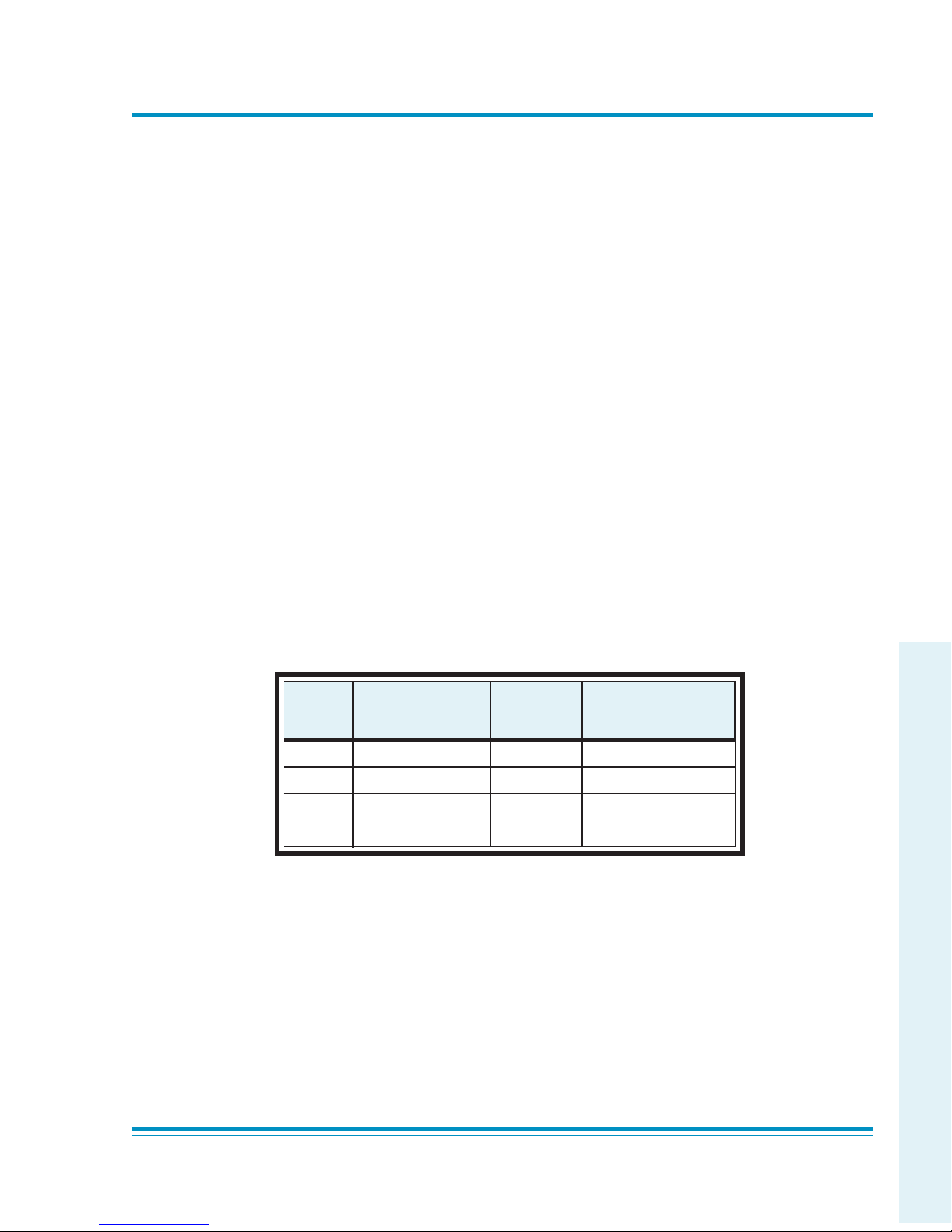
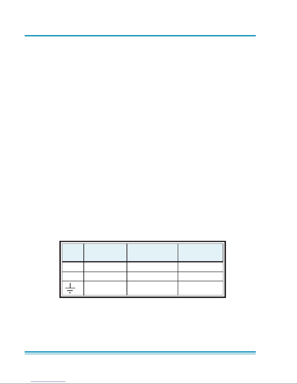
Symbols
This symbol, on the instrument, indicates that the user should refer to the user manual.
This symbol, on the instrument, indicates do not throw-away in domestic bin,
hazardous material, dispose correctly in accordance with local regulations.
This symbol, on the instrument, indicates d.c.
Page 7

iii
K114 Issue No. 9
Table of Contents
Preliminary pages
Introduction ............................................................................................................................................................ i
Scope ............................................................................................................................................................ i
Associated Publications ........................................................................................................................................................ ii
Symbols ............................................................................................................................................................ ii
Table of contents (this table) ............................................................................................................................................. iii
Abbreviations ............................................................................................................................................................ viii
Glossary ............................................................................................................................................................ ix
Returned Goods Procedure for Europe ......................................................................................................................... xi
Returned Materials Procedure for USA .......................................................................................................................... xii
Approved Service Agents ..................................................................................................................................................... xii
ATEX Certified ADTS Hand Terminal ................................................................................................................................ xiii
Pressure Units and Conversion Factors ........................................................................................................................xiv
Section page
1 DESCRIPTION
1.1 Introduction ................................................................................................................................................. 1-1
1.2 Operating Range and Performance ................................................................................................ 1-3
1.3 Operating Limits ........................................................................................................................................ 1-3
2 INSTALLATION
2.1 Packaging ..................................................................................................................................................... 2-1
2.2 Packaging for Storage and Transportation .................................................................................2-1
2.3 Electrical Connection .............................................................................................................................. 2-5
2.4 Pneumatic Pressure Connections ..................................................................................................... 2-7
2.5 Positioning of the ADTS 405 ................................................................................................................. 2-8
2.6 Positioning of the ADTS 405F .............................................................................................................. 2-9
3 OPERATION
3.1 Preparation .................................................................................................................................................. 3-1
3.2 Display Functions and Units of Measure ...................................................................................... 3-2
3.3 Quick Reference ......................................................................................................................................... 3-3
3.4 First Time Operators ................................................................................................................................ 3-4
3.5 Operation and Example Procedures ............................................................................................... 3-10
3.5.1 Checks Before Use .................................................................................................................... 3-10
3.5.2 Operating Procedures ............................................................................................................. 3-10
3.6 Power-up ....................................................................................................................................................... 3-10
3.7 Control or Measure Parameter .......................................................................................................... 3-11
3.8 Leak Testing the ADTS 405 ................................................................................................................... 3-12
3.9 Displays ......................................................................................................................................................... 3-15
3.10 Rate Timer Displays ................................................................................................................................. 3-17
3.11 Pt Only Display ........................................................................................................................................... 3-18
3.12 Changing the Display ............................................................................................................................. 3-18
3.13 Changing the Units .................................................................................................................................. 3-19
3.14 Limit Checking ............................................................................................................................................ 3-19
Aircraft System Protection ...................................................................................................................3-21
Mach Test and Constant Mach .......................................................................................................... 3-21
CONTENTS
Page 8

iv
K114 Issue No. 9
Table of Contents (contd)
Section page
True Airspeed ..............................................................................................................................................3-21
Airspeed Switch Test ............................................................................................................................... 3-22
Engine Pressure Ratio (EPR) ................................................................................................................. 3-23
3.15 Testing Aircraft Systems or UUT ....................................................................................................... 3-24
3.15.1 Go to Ground and Shut-Down ............................................................................................ 3-24
3.16 Options ........................................................................................................................................................... 3-25
SCPI IEEE 488 Option ............................................................................................................................... 3-25
Altimeter Encoder Option ..................................................................................................................... 3-25
ARINC 429 Option ..................................................................................................................................... 3-25
3.17 SETUP and CONFIGuration ...................................................................................................................3-26
3.18 Quick Reference ......................................................................................................................................... 3-26
4 MAINTENANCE
4.1 Introduction ................................................................................................................................................. 4-1
4.2 Materials........................................................................................................................................................ 4-2
4.3 Maintenance Tasks .................................................................................................................................. 4-3
4.4 Routine Maintenance .............................................................................................................................. 4-4
5 TESTING AND FAULT FINDING
5.1 Introduction ................................................................................................................................................. 5-1
5.2 Standard Serviceability Test ............................................................................................................... 5-2
5.3 Self-test Errors ............................................................................................................................................ 5-4
5.4 Venting after Over-pressure ............................................................................................................... 5-4
5.5 Fault Diagnosis .......................................................................................................................................... 5-5
5.6 Further Testing ........................................................................................................................................... 5-8
Test Environment and Preliminary Operations .......................................................... 5-8
Pressure Leak Check ...............................................................................................................5-8
Vacuum Leak Check ................................................................................................................ 5-9
Controller Stability .................................................................................................................... 5-10
5.7 Testing an Option Facility .....................................................................................................................5-11
Testing the IEEE 488 Facility................................................................................................................ 5-11
Configuring and Enabling the IEEE 488 Facility ......................................................................... 5-11
Programming a Test of the IEEE 488 Facility .............................................................................. 5-12
Connection of the IEEE 488 Facility ................................................................................................. 5-13
Testing the Altimeter Encoder Option............................................................................................. 5-14
Configuring and Enabling the Altimeter Encoder Option...................................................... 5-14
Optional cable (AAU-32) ......................................................................................................................... 5-15
Testing the ARINC 429 Option ............................................................................................................ 5-16
Configuring and Enabling the ARINC 429 Option ..................................................................... 5-16
5.8 Fault Finding ................................................................................................................................................ 5-17
5.8.1 Error Messages ...........................................................................................................................5-17
5.8.2 Warning Messages ................................................................................................................... 5-18
6 REFERENCE and SPECIFICATION
6.1 Introduction ................................................................................................................................................. 6-1
6.2 Main Pressure Display ............................................................................................................................ 6-1
F1 - F4 ............................................................................................................................................. 6-1
ALT Ps .............................................................................................................................................. 6-2
Druck ADTS 405 User Manual
Page 9

v
K114 Issue No. 9
Table of Contents (contd)
Section page
SPEED Qc ....................................................................................................................................... 6-2
MACH Pt ......................................................................................................................................... 6-3
EPR .................................................................................................................................................... 6-4
ROC Ps RATE ................................................................................................................................ 6-4
RATE TIMER ................................................................................................................................... 6-4
HOLD ............................................................................................................................................... 6-5
RATE ................................................................................................................................................. 6-6
LEAK MEASURE/CONTROL ..................................................................................................... 6-6
GROUND ........................................................................................................................................ 6-7
PORT ................................................................................................................................................ 6-9
REMOTE .......................................................................................................................................... 6-9
PRINT ............................................................................................................................................... 6-9
EXECUTE TEST PROGRAM ...................................................................................................... 6-10
HELP ................................................................................................................................................. 6-12
or (nudge keys) .................................................................................................................. 6-12
0 to 9 ................................................................................................................................................ 6-12
-000 .................................................................................................................................................. 6-13
CLEAR/QUIT .................................................................................................................................. 6-13
ENTER .............................................................................................................................................. 6-14
CLEAR/QUIT + ENTER (ABORT) .............................................................................................................6-14
6.3 SET-UP ............................................................................................................................................................ 6-15
FULL SET-UP ................................................................................................................................................ 6-15
SETUP, [UNITS] ............................................................................................................................ 6-16
SETUP, [LIMITS] ........................................................................................................................... 6-16
SETUP, [OSC] ................................................................................................................................ 6-17
SETUP, [MORE], [CONTROL],[Ps Pt DUAL] ....................................................................... 6-17
SETUP, [MORE], [DISPLAYS/OPTIONS],[DISPLAY TYPE] ............................................. 6-18
SET-UP, [MORE], [DISPLAYS/OPTIONS],[OPTIONS]...................................................... 6-20
SETUP, [MORE], [CLOSE OUTPUT VALVES]...................................................................... 6-20
SETUP, [MORE], [OPEN OUTPUT VALVES] ....................................................................... 6-20
SET-UP, [MORE], [SYSTEM SELF TEST]............................................................................... 6-20
SET-UP, ALT .................................................................................................................................. 6-21
SET-UP, SPEED [AUTO ZERO] ................................................................................................ 6-21
SET-UP, SPEED [CAS/TAS] ...................................................................................................... 6-21
SET-UP, SPEED [Pt TEMPERATURE] .................................................................................... 6-23
SET-UP, MACH ............................................................................................................................. 6-23
SET-UP, RATE TIMER ................................................................................................................................. 6-23
SET-UP, RATE ............................................................................................................................... 6-23
SET-UP, LEAK MEASURE CONTROL, [AUTO LEAK] ....................................................... 6-24
SET-UP, LEAK MEASURE CONTROL, [AUTO LIMIT] ...................................................... 6-24
SET-UP, GROUND .......................................................................................................................6-24
SET-UP, PORT ............................................................................................................................... 6-24
SET-UP, PRINT,[DATE/TIME]................................................................................................... 6-2
4
SET-UP, EXECUTE TEST PROGRAM ..................................................................................... 6-24
SET-UP, HELP ............................................................................................................................... 6-25
SET-UP,
or (nudge keys) ................................................................................................ 6-25
CONTENTS
Page 10

vi
K114 Issue No. 9
Table of Contents (contd)
Section page
MINIMUM SET-UP ............................................................................................................................................................ 6-26
SETUP, [UNITS], [AERO] ........................................................................................................... 6-26
SETUP, [UNITS], [PRESS] ..........................................................................................................6-26
SETUP, [LIMITS] ........................................................................................................................... 6-26
SETUP, ALT/Ps.............................................................................................................................. 6-27
SETUP, PORT ................................................................................................................................. 6-27
SETUP, HELP ................................................................................................................................. 6-27
6.4 CONFIGURATION ....................................................................................................................................... 6-28
Procedure...................................................................................................................................... 6-28
Functions ....................................................................................................................................... 6-28
CONFIG,[UNITS] .......................................................................................................................... 6-29
CONFIG, [LIMITS],[EDIT LIMITS],[EDIT EXISTING] ..........................................................6-29
NAME ............................................................................................................................................... 6-30
MIN ALT,MAX ALT, MIN CAS, MAX CAS ............................................................................. 6-30
MAX MACH .................................................................................................................................... 6-30
MAX ROC, MAX RATE CAS ....................................................................................................... 6-30
MIN Ps, MAX Ps, MIN Qc, MAX Qc ....................................................................................... 6-30
MAX RATE Ps, MAX RATE Qc.................................................................................................. 6-30
ARINC LIMITS ............................................................................................................................... 6-30
ALTITUDE CORRECTION ..........................................................................................................6-31
SAVING LIMITS ............................................................................................................................. 6-31
CONFIG, [LIMITS],[EDIT LIMITS],[MAX LIMITS] ................................................................ 6-32
CONFIG, [LIMITS],[EDIT LIMITS],[EDIT NEW] ................................................................... 6-32
CONFIG, [LIMITS],[CLEAR LIMITS] ........................................................................................6-32
CONFIG, [LIMITS],[LOCK AIRCRAFT] ...................................................................................6-32
CONFIG, [LIMITS],[DEFAULT AIRCRAFT] ........................................................................... 6-32
CONFIG, [MORE],[CONTROL],[CONTROL MODE] .......................................................... 6-32
CONFIG, [MORE],[CONTROL],[CONTROL LOCK] ...........................................................6-32
CONFIG, [MORE],[DISPLAY/OPTIONS],[DISPLAY TYPE] .............................................. 6-32
CONFIG, [MORE],[DISPLAY/OPTIONS],[OPTIONS] ........................................................ 6-32
CONFIG, [MORE],[DATE/FORMAT] ....................................................................................... 6-32
CONFIG, [MORE],[SETUP MODE] .......................................................................................... 6-33
FULL ................................................................................................................................................. 6-33
MINIMUM ....................................................................................................................................... 6-33
OFF ................................................................................................................................................... 6-33
CONFIG, SPEED,[AUTO ZERO] ............................................................................................... 6-33
CONFIG, SPEED,[CAS/TAS] ..................................................................................................... 6-33
CONFIG, SPEED,[Pt TEMPERATURE] ................................................................................... 6-33
CONFIG, RATE TIMER ................................................................................................................6-33
CONFIG, RATE .............................................................................................................................. 6-33
CONFIG, LEAK MEASURE, [AUTO LEAK ON/OFF] .........................................................6-33
CONFIG, LEAK MEASURE, [AUTO LEAK LOCK] ..............................................................................6-33
CONFIG, LEAK MEASURE, [AUTO LIMIT ON/OFF] ......................................................................... 6-33
CONFIG, LEAK MEASURE, [AUTO LIMIT LOCK] ..............................................................................6-33
CONFIG, GROUND ..................................................................................................................................... 6-33
Druck ADTS 405 User Manual
Page 11

vii
K114 Issue No. 9
Table of Contents (contd)
Section page
CONFIG, PORT ............................................................................................................................. 6-34
CONFIG, REMOTE ....................................................................................................................... 6-34
CONFIG, ETP,[AUTO RUN] ....................................................................................................... 6-34
CONFIG, ETP,[ERASE PROGRAMS] ...................................................................................... 6-34
CONFIG, ETP,[RESULT] ............................................................................................................. 6-34
CONFIG,
or (nudge keys) ............................................................................................... 6-34
CONFIG, 000 ................................................................................................................................................ 6-34
6.5 Specification ................................................................................................................................................ 6-35
Zone 2 Hazardous Area Definition ................................................................................................... 6-42
List of Illustrations
Figure page
Figure 1-1 ADTS 405 General View.......................................................................................................................... 1-2
Figure 1-2 ADTS 405F General View ....................................................................................................................... 1-2
Figure 2-1 Equipment and Parts .............................................................................................................................. 2-3
Figure 2-2 ADTS 405 Altitude Reference .............................................................................................................. 2-8
Figure 2-3 ADTS 405F Altitude Reference ............................................................................................................ 2-9
Figure 2-4 ADTS 405 General View.......................................................................................................................... 2-10
Figure 2-5 ADTS 405 Rear Panel View ................................................................................................................... 2-11
Figure 2-6 ADTS 405F General View ....................................................................................................................... 2-12
Figure 3-1 Front Panel ................................................................................................................................................... 3-2
Figure 3-2 Main Pressure Display (Leak Measure Mode) .............................................................................. 3-12
Figure 3-3 Main Pressure Display (Control Mode)............................................................................................ 3-13
Figure 3-4 Single Display ............................................................................................................................................. 3-15
Figure 3-5 Dual Display ................................................................................................................................................ 3-16
Figure 3-6 Triple Display .............................................................................................................................................. 3-16
Figure 3-7 Rate Timer Display Aeronautical Units .......................................................................................... 3-17
Figure 3-8 Rate Timer Display Pressure Units ................................................................................................... 3-17
Figure 3-9 Pt Only Display ........................................................................................................................................... 3-18
Figure 5-1 Fault Finding Chart .................................................................................................................................. 5-6
Figure 6-1 Altitude Correction Rack Mounting .................................................................................................. 6-22
Figure 6-2 Altitude Correction On-aircraft .......................................................................................................... 6-22
Figure 6-3 ARINC 565 Operating Limits ................................................................................................................ 6-31
List of Tables
Table page
2-1 Parts List ........................................................................................................................................................ 2-4
4-1 Maintenance Chart .................................................................................................................................. 4-1
4-2 Materials List ............................................................................................................................................... 4-2
4-3 Tool and Test Equipment Requirements ....................................................................................... 4-2
5-1 Fault Finding ................................................................................................................................................ 5-7
5-2 Error Messages .......................................................................................................................................... 5-17
5-3 Warning Messages ................................................................................................................................... 5-18
Page 12

viii
K114 Issue No. 9
Druck ADTS 405 User Manual
Abbreviations
The following abbreviations are used in this manual; the abbreviations are the same in the singular and plural.
A Ampere
abs Absolute
a.c. Alternating current
ALT Altitude
ATEX Equipment for Use in Potentially Explosive Atmosheres
CAS Calibrated airspeed
d.c. Direct current
e.g. For example
EOC End of conversion
EPR Engine pressure ratio
EPROM Electrically programmable read only memory
etc. And so on
Fig. Figure
ft Foot
g Gauge
Hg Mercury
Hz Hertz
IAS Indicated airspeed
i.e. That is
IEEE 488 Institute of Electrical and Electronic Engineers standard 488 data
in Inch
kg Kilogram
LED Light emitting diode
m Metre
mA Milliampere
max Maximum
mbar Millibar
min Minute or minimum
mm Millimetre
mV Millivolts
No. Number
N.m. Newton metre
Para. Paragraph
Ps Static pressure
psi Pounds per square inch
Pt Total pressure
Qc Differential pressure Ps-Pt
QFE Local atmospheric pressure
QNH Barometric pressure at sea level
ROC Rate of climb
SCPI Standard commands for programmable instruments
TAS True airspeed
TE Test equipment
V Volts
Vc Calibrated velocity
Vt True velocity
+ve Positive
-ve Negative
°C Degrees Celsius
°F Degrees Fahrenheit
Page 13

ix
K114 Issue No. 9
Glossary
Terminology
The terminology used in this manual is specific and individual interpretation must not be
introduced. The terms are defined as follows:
Adjust To bring to a more satisfactory state; to manipulate controls, levers, linkages,
etc. to return equipment from an out-of-tolerance condition to an in-tolerance
condition.
Align To bring into line; to line up; to bring into precise adjustment, correct relative
position or coincidence.
Assemble: To fit and secure together the several parts of; to make or form by combining
parts.
Calibrate: To determine accuracy, deviation or variation by special measurement or by
comparison with a standard.
Check: Make a comparison of a measure of time, pressure, temperature, resistance,
dimension or other quality with a known figure for that measurement.
Disconnect: To detach the connection between; to separate keyed or matched equipment
parts.
Dismantle: To take apart to the level of the next smaller unit or down to all removable parts.
Examine: To perform a critical visual observation or check for specific conditions; to test the
condition of.
Fit: Correctly attach one item to another.
Inspect: Review the work carried out by Specialists to make sure it has been performed
satisfactorily.
Install: To perform operations necessary to properly fit an equipment unit into the next
larger assembly or system.
Maintain: To hold or keep in any particular state or condition especially in a state of
efficiency or validity.
Make sure: To confirm that a proper condition exists; to find out with certainty.
Operate: Make sure that an item or system functions correctly as far as possible without
the use of test equipment or reference to measurement.
Power-up: To perform operations necessary to switch on a system ready for use.
Glossary
Page 14

x
K114 Issue No. 9
Power-down: To perform operations necessary to safely switch off a system after use.
Readjust: To adjust again; to move back to a specified condition; to bring back to an
in-tolerance condition.
Reconnect: To rejoin or refasten that which has been separated.
Refit: Fit an item which has previously been removed.
Remove: To perform operations necessary to take an equipment unit out of the next larger
assembly or system. To take off or eliminate. To take or move away.
Repair: To restore damaged, worn out or malfunctioning equipment to a serviceable,
usable or operable condition.
Replace: Remove an item and fit a new or a serviced item.
Reset: To put back into a required position, adjustment or condition.
Service: To perform such operations as cleaning, lubricating and replenishing to prepare for
use.
Test: Ascertain by using the appropriate test equipment that a component or system
functions correctly.
Druck ADTS 405 User Manual
Page 15

xi
K114 Issue No. 9
Returned Goods Procedure
for Europe
Should the unit become unserviceable and require repair it can be returned to the Druck
Service Department.
Please contact our Service Department, either by 'phone, fax or e-mail to obtain a Returned
Goods Authorization (RGA) number, providing the following information:
Product (i.e. ADTS 405)
Pressure medium (i.e. air, nitrogen)
Serial number
Details of defect/work to be undertaken
Operating conditions
Safety Precautions
You must also tell us if the product has been in contact with anything hazardous or toxic and
the relevant COSH references and precautions to be taken when handling.
Important notice
Service by unauthorized sources will affect the warranty and may not guarantee further
performance.
Page 16

xii
K114 Issue No. 9
Returned Material Procedure
for USA
Should the equipment become unserviceable it can be returned to the Druck Service
Department.
Please contact our Service Department, either by 'phone, fax or e-mail to obtain a Returned
Material Authorization (RMA) number, providing the following information:
Product (i.e. ADTS 405)
Pressure medium (i.e. air, nitrogen)
Serial number
Details of defect/work to be undertaken
Operating conditions
Safety Precautions
You must also tell us if the product has been in contact with anything hazardous or toxic and,
the relevant MSDS references and precautions to be taken when handling.
Important notice
Service by unauthorized sources will affect the warranty and may not guarantee further
performance.
Approved Service Agents
For the list of service centres visit our web site:
www.gesensing.com
Page 17
xiii
K114 Issue No. 9
ATEX Certified ADTS Hand Terminal
CONDITIONS OF USE
The ATEX certified ADTS hand terminal supplied with the ADTS 405 can be used in zone 2
hazardous areas in accordance with the ATEX certification document and schedule.
ATEX Certificate of Conformity
No. Baseefa05ATEX0192
BASEEFA being an Approved Certification Body, in accordance with Article 14 of the Council
Directive of the European Communities of 18th December, 1975 (76/117/EEC) certifies that
the apparatus has been found to comply with harmonised European Standards:
EN 60079-15: 2003
and has successfully met the examination and test requirements recorded in confidential
report number:
05(C)0154 (Baseefa) dated 12th October 2005
NOTE: Refer to pages 2/2 of the Certificate of conformity for electrical connection parameters.
Rated Voltage = 32Vdc.
Marking detail:
ADTS Hand Terminal
Baseefa05ATEX0192
II 3G IP54
Baseefa05ATEX0192 (EC type examination certificate number)
EEx nA nL IIC T4 (-25°C
<T
amb
<=55°C)
Druck, LE6 0FH, UK
6 - 32V
Power
3W Max
SPECIAL CONDITION OF USE
• The power supplies must be isolated when connecting the ADTS hand terminal in the
hazardous area.
• The ADTS hand terminal must not be disconnected when energized in the hazardous
area.
• The ADTS hand terminal is a non-serviceable component. If the ADTS hand terminal
becomes unserviceable it can only be replaced by another ATEX compliant hand
terminal.
Page 18

xiv
K114 Issue No. 9
Table of pressure units and conversion factors
Unit Conversion
To convert FROM pressure VALUE 1 in pressure UNITS 1
TO pressure VALUE 2 in pressure UNITS 2, calculate as follows:
VALUE 2 = VALUE 1 x
FACTOR 1
FACTOR 2
Note
The conversion factor for pressure units referenced [1] are calculated for a water temperature of 4°C.
Pressure units referenced [2] are calculated for a water temperature of 68°F these units are normally
used in the USA.
tinuerusserP )slacsaP(rotcaF tinuerusserP )slacsaP(rotcaF
rab000001tf/fbl
2
3088.74
ni/fbl
2
)isp(67.4986gHni93.6833
Hm
2
O56.6089Hni
2
]1[O980.942
rabm001Htf
2
]1[O70.9892
mc/fgk
2
5.66089mta0.523101
m/fgk
2
56608.9tf/ldp
2
61884.1
gHmm223.331mc/nyd
2
1.0
gHmc22.3331rabh00000001
gHm0.223331tf/fnot
2
)KU(0.252701
H/mm
2
]1[O56608.9ni/fnot
2
)KU(00344451
H/mc
2
]1[O5660.89Hni
2
]2[)ASU(O53146.842
m/N
2
1Htf
2
]2[)ASU(O3896.3892
aPh001mm/pk
2
0566089
aPk0001mc/pk
2
5.66089
aPM0000001m/pk
2
56608.9
rrot223.331
Pressure units and conversion factors
Page 19

1 - 1Description
K114 Issue No. 9
1
1 DESCRIPTION
1.1 Introduction
There are two versions of the ADTS 405, a 19", 6U high (10½”) rack-mounted unit and a
flight line unit.
The ADTS 405 is a rack-mounted system and, with external pressure and vacuum supplies
connected, provides measurement and control for leak checks, calibration accuracy
checks and functional tests of air data instruments, components and systems.
The ADTS 405F is a self-contained flight-line air data test system providing complete
pressure and vacuum measuring and control for on-aircraft sense and leak testing,
calibration accuracy checks and functional tests of air data instruments, components and
systems. The unit comprises an electronics rack and pump rack enclosed in a high density,
polyethylene case.
The ADTS 405 displays and operates in either units of pressure measurement or aeronautical
units. In the control mode, the rate that the pressures change towards new set-points can
be controlled in true aeronautical rate units.
There are two independent pneumatic channels connect to the aircraft or instrument
systems, one for static and one for pitot. They can be operated as measure only channels
with leak testing facility or each can be control channels producing true pressure
conditions for altitude and airspeed.
To protect sensitive instruments and equipment a `ground' facility automatically and
safely controls both channels to atmospheric pressure at the previously entered rates of
change and then informs the operator when both channels are safely at `ground'.
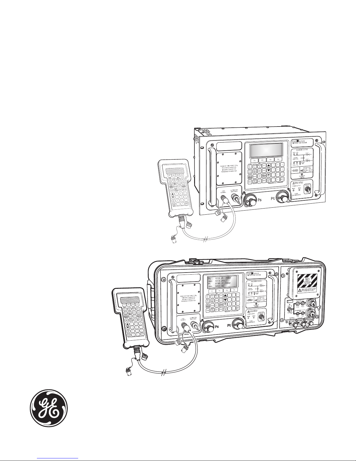
The operator interface is either an ATEX certified hand terminal connected to the front
panel or the key pad and display on the front panel. Both provide information and control
selections for the user through the keys and display. The unit can also be controlled
remotely using the IEEE 488 communications interface. The front panel contains the
operate switch and a mimic panel with LED indicators showing the operation of the
solenoid-operated pneumatic valves.
The pump rack, on the ADTS 405F, produces pressure and vacuum supplies for the
electronics rack and for external services. Located on the front panel, the external
connectors provide for external pressure and vacuum supplies (EXT PRESSURE and EXT
VACUUM) and an auxiliary static (vacuum) output (AUX). The rack is cooled by a fan located
under a protective cover on the front panel. The power supply connection for the ADTS
405F is located on the front panel.
Page 20

Druck ADTS 405 User Manual
1 - 2
K114 Issue No. 9
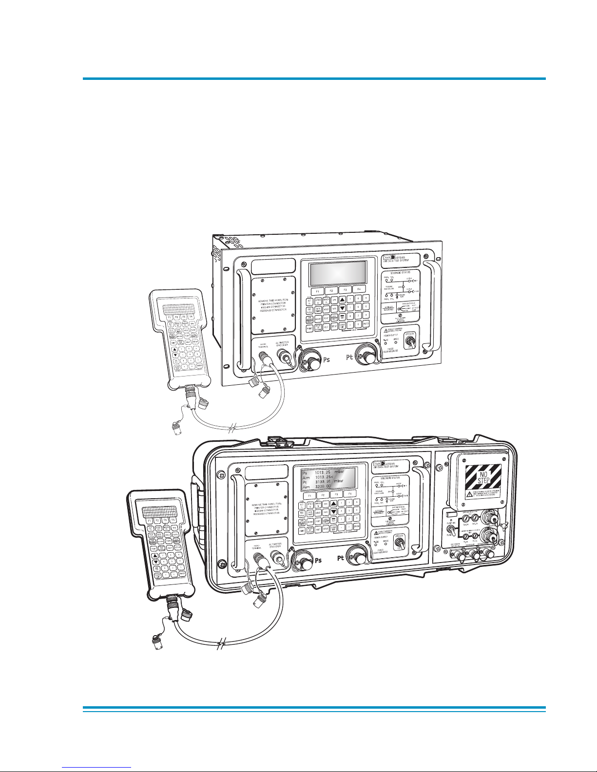
FIGURE 1-2 ADTS 405F GENERAL VIEW
FIGURE 1-1 ADTS 405 GENERAL VIEW
DRUCKADTS 405
ATEXCOMPLIANT
HANDTERMINAL
DONOT DISCONNECT WHEN
ENERGIZEDIN THE HAZARDOUS AREA
Ps 1013. 25 mbar
Aim 1013. 25<
Pt 3199. 91 mbar
Aim 3200. 00
DONOT DISCONNECT WHEN
ENERGIZEDIN THE HAZARDOUS AREA
DRUCKADTS 405
ATEXCOMPLIANT
HANDTERMINAL
Page 21

1 - 3Description
K114 Issue No. 9
1
1.2 Operating Range and Performance
The ADTS 405 is supplied in one of two full-scale ranges (850 knots or 1000 knots) for
measurement and control of the pitot pressure channel.
Operating limits are set, pre-defined tabular limits known as STANDARD, CIVIL and MAX
these can be selected through the SETUP menu (see Reference section 6). Operators
may also configure the display to aeronautical or pressure units but should be aware
that when units of pressure are selected, wider full-scale pressure limits will be enabled
for some parameters.
1.3 Operating Limits
The following sets of operating limits are supplied with the ADTS 405.
850 knot range operating limits
retemaraP stimiLxaM stimildradnatS stimilliviC
tlAniMtf000,3-tf000,2-tf000,1-
tlAxaMtf000,501tf000,08tf000,05
SACniMstk001-stk0.0stk0
SACxaMstk058stk05
8stk054
sPniMrabm0.3rabm516.72rabm279.511
sPxaMrabm00.5531rabm756.8801rabm604.0501
cQniMrabm00.253,1-rabm0.0rabm0
c
QxaMrabm00.007,1rabm00.8861rabm10.863
hcaMxaM53.215.21
CORxaMnim/tf000,001nim/tf000,9nim/tf000,6
SACetaRxaMnim/stk
000,2nim/stk006nim/stk006
sPetaRxaMnim/rabm00.000,01nim/rabm00.002nim/rabm00.001
cQetaRxaMnim/rabm00.000,01nim
/rabm00.002nim/rabm00.001
stimiLCNIRAFFOFFOFFO
noitcerroCtlAtf0tf0tf0
Page 22

Druck ADTS 405 User Manual
1 - 4
K114 Issue No. 9
retemaraP stimiLxaM stimildradnatS stimilliviC
tlAniMtf000,3-tf000,3-tf000,1-
tlAxaMtf000,501tf000,08tf000,05
SACniMstk001-stk0stk0
SACxaMstk000,1stk00
0,1stk054
sPniMrabm0.3rabm516.72rabm279.511
sPxaMrabm00.5531rabm920.821,1rabm604.0501
cQniMrabm00.253,1-rabm303.6
1-rabm0
cQxaMrabm00.005,2rabm05.094,2rabm10.863
hcaMxaM79.4151
CORxaMnim/tf000,001nim/tf000,51nim/tf000,6
SACetaRxa
Mnim/stk000,2nim/stk007nim/stk006
sPetaRxaMnim/rabm00.000,01nim/rabm00.002nim/rabm00.001
cQetaRxaMnim/rabm00.0
00,01nim/rabm00.002nim/rabm00.001
stimiLCNIRAFFOFFOFFO
noitcerroCTLAtf0tf0tf0
1000 knot range operating limits
Page 23

K114 Issue No. 9
Installation 2 - 1
2
2 INSTALLATION
2.1 Packaging
Packaging List - ADTS 405
i) Rack ADTS 405
ii) Power supply cable
iii) User Manual (this publication)
iv) Output, hose, 2.5m, red, AN6 - open
v) Output, hose, 2.5m, blue, AN4 - open
vi) Input, hose, 2.5m, green, AN6 - open
vii) Input, hose, 2.5m, yellow, AN4 - open
viii) Spare fuses (2 off)
ix) Plug, expansion port
Packaging List - ADTS 405F
i) Flight line ADTS 405F
ii) Accessory bag
iii) Power supply cable
iv) Hand terminal
v) Hand terminal cable - 2 m
vi) Hand terminal cable - 18 m
vii) Output, hose, 2.5m, red, AN6 - open
viii) Output, hose, 2.5m, blue, AN4 - open
ix) User Manual (this publication)
x) Spare fuses (2 off)
2.2 Packaging for Storage or Transportation
To store the unit or to return the unit for calibration or repair carry out the following
procedures:
1. Pack the unit as detailed in the following procedure.
2. To return the unit for calibration or repair complete the return goods procedure
as detailed in the preliminary pages.
On receipt of the ADTS 405 check the contents of the packaging against the following
lists:
Page 24

K114 Issue No. 9
2 - 2 Druck ADTS 405 User Manual
Procedure
The unit should be at zero/ambient pressure. Disconnect the hose assemblies and
stow in the shoulder bag.
Switch OFF and disconnect from the electrical power supply. Disconnect the
power supply cable and the hand terminal cable. Disconnect the hand terminal
cable from the hand terminal.
Stow the power supply cable, hand terminal cable and the hand terminal in the
ADTS 405F lid. For ADTS 405 rack units these items should be placed in a sealed
polythene bag.
Fit the lid to the unit.
If available, use the original packing material. When using packing materials other
than the original, proceed as follows.
Wrap unit in polyethylene sheeting.
Select a double-wall cardboard container. Inside dimensions must be at least
15 cm greater than the equipment. The carton must meet test strength
requirements of >125 kg.
Protect all sides with shock-absorbing material to prevent equipment movement
within the container.
Seal carton with approved sealing tape.
Mark carton “FRAGILE” on all sides, top, and bottom of shipping container.
Environment
The following conditions apply for both shipping and storage:
Temperature Range-40° to +70°C (-40° to +158°F)
Altitude......................... Up to 15,000 feet (4,570 metres)
Page 25
K114 Issue No. 9
Installation 2 - 3
2
DONOT DISCONNECT WHEN
ENERGIZEDIN THE HAZARDOUS AREA
DRUCK ADTS 405
ATEXCOMPLIANT
HAND TERMINAL
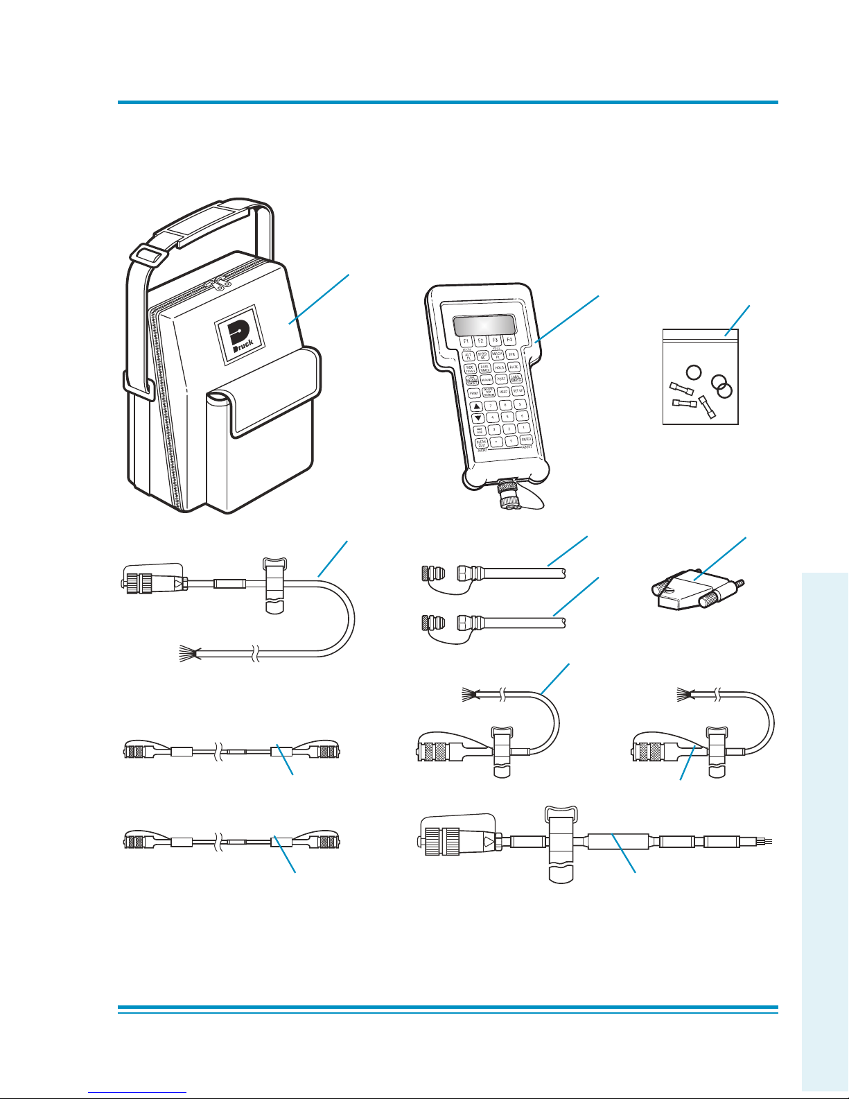
FIGURE 2.1 EQUIPMENT AND PARTS
1
4
8
2
6
11a
5
12
10
2m
18m
9
3
13
Page 26

K114 Issue No. 9
2 - 4 Druck ADTS 405 User Manual
TABLE 2-1 PARTS LIST
oN rebmuNtraP noitpircseD nOdesU
repytQ
yssa
1
0M-93-8271-504STDAredluohS,gaB
F504STDA
1
2
0M-63-8271-504STDAgniR-O/esuF,tiK
F504STDA
dna
504STDA
1
3
1M-73-8271-504STDA,lanimretdnaH
F504STDA
dna
504STDA
1
4
0M-74-8271-504STDA)dnEnepOV062(M5,rewoPCA,elbaC
F504STDA
dna
504STDA
1
5
0M-82-8271-504STDAM2lanimretdnaH,elbaC
F504STDA
dna
504STDA
1
a6
0M-72-8271-504STDAM81lanimretdnaH,elbaC
F504STDA
dna
504STDA
1
*b6
0M-92-8271-504STDA)noitpO(M03lanimretdnaH,elbaC
1
*7
0M-25-9271-504STDA)nepO/TSNAM5.2x2(rotpadaesoh,tiK
F504STDA
dna
504STDA
1
8
0M-16-9271-504STDA6NA,NPO/TS,der,)sP(citatS,esoH
)elbaliavasnoitpolaicepS(
F504STDA
dna
504STDA
1
9
0M-26-9271-504STDA4NA,NPO/TS,eulb,)tP(totiP,esoH
)elbaliavasnoitpolaicepS(
F504STDA
dna
504STDA
1
01
0M-43-8271-504STDA)dnEnepO()rotcennoCralucriC(CNIRA,elbaC
)noitpO(
F504STDA
dna
504STDA
1
a11
0M-53-8271-504STDA)dnEnepO(M6,redocnEretemitlA,elbaC
)noitpO(
F504STDA
dna
504STDA
1
*b11
0M-16-1981-504STDA)sretemitla23-UAA(M6,elbaCredocnEretemitlA
)noitpO(
1
21
0M-84-8271-504STDA)noitpO(M5,rewoPCD,elbaC
F504STDA
1
31
0M-22-1981-504STDAtropnoisnapxe,gulP
504STDA
1
ATEX certified
Page 27
K114 Issue No. 9
Installation 2 - 5
2
2.3 Electrical Connection
WARNINGS: 1 VOLTAGES IN EXCESS OF 30 VOLTS (RMS) AC OR 50VOLTS DC,
IN CERTAIN CIRCUMSTANCES, CAN BE LETHAL. CARE MUST BE TAKEN
WHEN WORKING ON LIVE, EXPOSED CONDUCTORS.
2 DO NOT DISCONNECT THE HAND TERMINAL WHEN ENERGIZED IN THE
HAZARDOUS AREA.
Power Supply Connection
The unit must be connected to the correct electrical power supply as stated, adjacent
to the power connector.
CAUTIONS:
1T
HE SUPPLY MUST PROVIDE CONNECTION TO A PROTECTIVE GROUND TERMINAL. THE UNIT
MUST
, AT ALL TIMES, BE CONNECTED TO THE SUPPLY EARTH (GROUND).
2T
HE POWER SUPPLY CABLE AND CONNECTOR MUST BE CORRECTLY RATED FOR THE POWER
SUPPLY
.
Note: The ADTS 405 is normally supplied with an approved power supply cable
for use in the country of delivery. This can limit the maximum supply
voltage that can be safely used.
e.g. a NEMA 5-15P terminated cable, for use in the U.S.A., is approved for a
maximum of 125 V ac; it must be replaced for a higher supply voltage.
ADTS 405 rack mounted units
Make sure that the power supply is off before connecting the power cable .
If required, connect the hand terminal to the connector using either the 2 metre or 18
metre cable.
Note: Connecting the hand terminal disables the front panel key-pad.
Fit the expansion port plug (item 13, Table 2-1) to the rear panel expansion port.
Note: For units used with the Druck PV 103 Pump Unit connect the expansion cable, supplied
with the PV 103, to the expansion port.
Pin European U.S. Function
Colour Color
1 Brown Black Live
4 Blue White Neutral
Centre Green/Yellow Green Protective Earth
(Ground)
Page 28
K114 Issue No. 9
2 - 6 Druck ADTS 405 User Manual
Note: The unit will not be damaged if AC power and DC power are connected at the same time.
Flight line units
Make sure that the power supply is off before connecting the power cable and hand
terminal cable.
Note: The flight line version power cable supplies both the electronics and pump racks.
If required, connect the hand terminal to the connector on the front panel using either
the 2 metre or 18 metre cable.
Note: Connecting the hand terminal disables the front panel key-pad.
The two fuses, located in the holders and mounted on the front panel, protect the
Electronics Rack and the Pump Rack. The fuses are connected in the live supply circuit
and are rated at:
5A anti-surge HBC 250V
An external earth (ground) cable may be connected to the stud on the front panel of
the pump rack to ensure integrity of the earth (ground) connection.
DC Power Option
The DC power option (nominal 28 V DC), can be an alternative power supply using an
additional connector. This is located on the rear of the rack (ADTS 405) or on the pump
front panel (ADTS 405F) both have the same connector details.
Pin European U.S. Function
Colour Color
1 Grey Gray +28V
2 White White 0V Return
Protective Earth Protective Ground Protective Earth
(Ground) (Ground)
Page 29

K114 Issue No. 9
Installation 2 - 7
2
2.4 Pneumatic Pressure Connections
ADTS 405 rack-mounted unit
Static (Ps) ............................................................................................................................ AN-6 37° flare
Pitot (Pt) ............................................................................................................................ AN-4 37° flare
Pressure supply ....................................................................................................................... AN-4 37° flare
Vacuum supply ........................................................................................................................ AN-6 37° flare
Connect pressure and vacuum supplies to the rear panel PRESSURE and VACUUM
connectors. The pressure supply should be clean, dry gas, nitrogen or air refer to the
specification.
Connect the Unit Under Test (UUT) to either the front panel or optional rear panel Ps
(static) and Pt (pitot) output connectors.
Note: Blanking caps must be fitted on unused front or rear outputs.
ADTS 405F flight line
Static (Ps) ............................................................................................................................ AN-6 37° flare
Pitot (Pt) ............................................................................................................................ AN-4 37° flare
Pressure supply ....................................................................................................................... AN-4 37° flare
Vacuum supply ........................................................................................................................ AN-6 37° flare
Auxiliary vacuum supply ..................................................................................................... AN-4 37° flare
In normal operation make sure that the correct blanking caps are fitted to the external
connectors.
The external pressure and vacuum connections are used when an external pump unit
supplies the pressure and vacuum. This may increase the maximum achievable rates
of change when connected to large volume systems.
The auxiliary vacuum, AUX VACUUM, can be used to supply the suction-type static
adaptors and provides a nominal 100 mbar (3 inHg) absolute vacuum. When not in
use, a blanking cap must be fitted.
Note: A leak of this blanking cap affects the performance of the ADTS 405F.
Page 30
K114 Issue No. 9
2 - 8 Druck ADTS 405 User Manual
Single channel operation
For single pipe testing of airspeed indicators or similar, requiring only Pt (pitot), connect
the UUT to Pt (pitot). The Ps (static) output must be left open to atmosphere (no
blanking cap) to provide a reference pressure.
Note: The Pt ONLY mode of operation must be used in this configuration.
For single pipe testing of altimeters or similar, requiring only Ps (static), connect the
UUT to Ps (static). The Pt (pitot) output should be left with a blanking cap fitted.
Note: The Ps ONLY mode of operation must be used in this configuration.
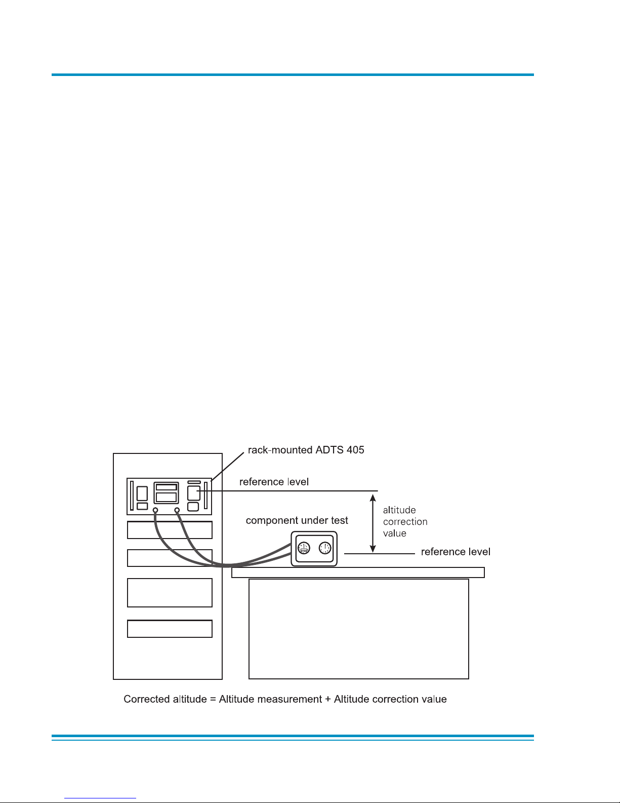
2.5 Positioning of the ADTS 405
It is important that the position of the ADTS 405 in relation to the components under
test is known. An altitude correction must be made to allow for the difference in height
between the reference level, indicated on the mimic panel, and the components under
test. The Reference section contains details of altitude correction (SETUP, ALTITUDE).
FIGURE 2-2 ADTS 405 ALTITUDE REFERENCE
WARNING: OBSERVE THE APPROPRIATE SAFETY
INSTRUCTIONS AND PROCEDURES DETAILED IN
THE COMPONENT MAINTENANCE MANUALS.
Page 31

K114 Issue No. 9
Installation 2 - 9
2
reference level
inst
AIR DATA
COMPUTER
STATIC
PITOT
reference level
altitude
correction
value
Corrected altitude = Altitude measurement - Altitude correction value
Zone 2 defined hazardous area
2.6 Positioning of the ADTS 405F
WARNING: DO NOT DISCONNECT THE ATEX CERTIFIED HAND TERMINAL WHEN
ENERGIZED IN THE HAZARDOUS AREA. THIS CAN CAUSE AN EXPLOSION.
To operate safely, the ADTS 405F must be placed outside the user defined zone 2
hazardous area. Only the ATEX certified hand terminal may be used inside the defined
zone 2 hazardous area (refer to section 6.5 for a definition).
It is important that the position of the ADTS 405F in relation to the aircraft altitude
sensors is known. An altitude correction must be made to allow for the difference in
height between the reference level and the aircraft's altitude sensors. The Reference
section contains details of altitude correction.
WARNING: OBSERVE THE APPROPRIATE SAFETY
INSTRUCTIONS AND PROCEDURES DETAILED IN
THE AIRCRAFT MAINTENANCE MANUALS.
F
IGURE 2-3 ADTS 405F ALTITUDE REFERENCE
Page 32

K114 Issue No. 9
2 - 10 Druck ADTS 405 User Manual
FIGURE 2-4 ADTS 405 GENERAL VIEW
Page 33

K114 Issue No. 9
Installation 2 - 11
2
FIGURE 2-5 ADTS 405 REAR PANEL VIEW
Page 34

K114 Issue No. 9
2 - 12 Druck ADTS 405 User Manual
FIGURE 2-6 ADTS 405F GENERAL VIEW
DONOT DISCONNECT WHEN
ENERGIZEDIN THE HAZARDOUS AREA
System
status
indicator
Solenoid
valve status
indicator
Key-pad
and
display
Cover plate
for option
connectors
Static
output
connector
Connector cable
(2m or 18m)
Hand
terminal
Pitot
output
connector
Altitude
reference
Auxiliary
Vacuum
input
connector
Vacuum
input
connector
Calibration
enable
switch
Power
supply
switch
Pump
switch
ARINC 429/
Altimeter
encoder
connector
(optional)
AC power
supply
connector
DC power
supply
connector
(optional)
DC and
AC power
supply
fuses
Pressure
input
connector
Fan
outlet
cover
Elapsed
time
indicator
DRUCK ADTS 405
ATEXCOMPLIANT
HAND TERMINAL
Page 35

K114 Issue No. 9
Druck ADTS 405 User Manual 3 - 1
3
3 OPERATION
3.1 Preparation
WARNING:
OBSERVE SAFETY PRECAUTIONS STATED IN LOCAL ORDERS AND THE
AIRCRAFT OR EQUIPMENT SERVICING PROCEDURES.
Make sure the electrical and pneumatic connectors, electrical cables and pipes and
positioning of the ADTS 405 comply with the instructions and requirements in Section 2
Installation.
Carry out the following before use:
If necessary, carry out the maintenance task detailed in Section 4.
Make sure the air data test system power supply switch on the front panel is set
to OFF. Connect the air data test system to the electrical supply, make sure the
supply includes a connection to a protective earth.
Inspect the pneumatic hoses for damage, ingress of dirt and moisture. Make
sure the aircraft adaptors are serviceable.
Connect, to the air data test system, the hoses necessary for the test procedures to be
carried out: red hose to the STATIC output (Ps), blue hose to the PITOT output (Pt).
Temporarily seal the free ends of the hoses.
Note: When connected, take care not to kink or stand on the hoses.
Connect the hand terminal to the air data test system through the HAND TERMINAL
connector on the front panel. If necessary, connect the hand terminal through the
extension cable.
Before use, the ADTS 405 should be tested, for first time users see section 3.4, for users
requiring more operating detail see section 3.5.
This section contains a quick reference chart showing all the functions of the key-pad.
Further quick reference charts show the set-up and configuration settings for each
key-pad function.
Review and become familiar with the whole procedure before starting the test process
on an aircraft or component.
Page 36

K114 Issue No. 9
3 - 2 Operation
3.2 Display Functions and Units of Measure
When operating in either pressure measuring or pressure controlling modes, the ADTS
405 can display the following information:
Aeronautical Functions Display Abbreviation Displayed Units
(if applicable)
Altitude ALT ft, m
Calibrated and True Airspeed CAS, TAS kts, km/h, mph
Mach MACH Rate of Climb ROC ft/m, m/m, m/s, hm/m
Rate of Airspeed Rt CAS, kts/m, km/h/m, mph/m
Rate of Mach RtMCH Mach/m
Pressure Functions Display Abbreviation Displayed Units
(if applicable)
Static (Absolute) Ps [P]
Pitot (Absolute) Pt [P]
Dynamic or Impact (Differential) Qc [P]
Engine Pressure Ratio EPR Rate of Ps Rt Ps [P] /m
Rate of Pt Rt Pt [P] /m
Rate of Qc Rt Qc [P] /m
Rate of EPR Rt EPR EPR/m
Where [P] is the currently selected pressure units from the following list:
mbar, inHg, mmHg, inH2O (4°C), inH2O (20°C), psi, hPa, kPa, inH2O (60°F), kg/cm2, %FS
FIGURE 3-1 FRONT PANEL
Page 37

K114 Issue No. 9
Druck ADTS 405 User Manual 3 - 3
3
the display shows the main pressure display (Leak Measure or Control mode).
KEY-PAD FUNCTION
F1-F4
ALT Ps
SPEED Qc
MACH Pt
EPR
ROC Ps RATE
RATE TIMER
F1
F2
F3
HOLD
RATE
LEAK MEASURE/CONTROL
GROUND
[GO TO GROUND]
[DISPLAY QFE]
[DISPLAY QNH]
PORT
REMOTE
PRINT
[ALPHA]
[BACK]
data entry
EXECUTE TEST PROGRAM
[NEXT]
[PREV]
[RUN]
F1
F2
HELP
SETUP
See QUICK REFERENCE -
SETUP or MINIMUM SETUP
SETUP + F1
See QUICK REFERENCE - CONFIG
(nudge up)
(nudge down)
0-9
-000
CLEAR/QUIT
ENTER
CLEAR/QUIT + ENTER
Function keys for menus
Altitude (Aeronautical units) or Ps (Pressure units)
Airspeed (Aeronautical units) or Qc (Pressure units)
Mach (Aeronautical units) or Pt (Pressure units)
Engine Pressure Ratio (pressure units only)
Rate of Climb (Aeronautical units) or Rate of Ps (Pressure units)
Start timing rate of change
Wait and time choice 1
Wait and time choice 2
Wait and time choice 3
Hold pressure at present value - Press again to release
Rate of change of Pitot parameter - Press Pitot parameter then RATE
Switches between measure mode (for leak testing) and control mode
Controls Ps to atmospheric pressure and Qc to zero at current rates of
change
Display local atmospheric (ground) pressure
Display sea level equivalent of local atmospheric pressure
See Line Switching Unit User Manual
Switches (toggles) between remote and local operation
Prints current parameter values
Inserts alphabet character in user text
Deletes last character of user text
Numeric entry for user text
Execute down-loaded Test Programs
Select next listed test program
Select previous listed test program
Execute selected test program
Execute all tests in the test program
Selects and executes a specific test program
Press HELP then other key for further information
Temporary set-up - lost at power down
Configuration - changes power-up defaults
Hold F1 while pressing SETUP - then enter PIN
Increases aim value
Decreases aim value
Number entry
Minus sign for first number entry 000 (thousand) if not first number of entry
Clear number entry - quit from menu or clear warning message
Complete number entry
ABORT - restart with power-up
Key/selection Function and comments
3.3 Quick Reference
The quick reference chart shows normal operation key functions. In the key/selection column the following applies:
ALT - Key.
[NEXT] - Item in menu (soft key).
(SINGLE DOUBLE) - Sequence of parameters selected by NEXT key.
(craft1 craft2...) - Sequence of names selected by NEXT key.
data entry - Enter number from key-pad.
Page 38

K114 Issue No. 9
3 - 4 Operation
3.4 First Time Operators
The following sequences of operation should be used by first time operators and by
operators that use the equipment occasionally. For regular users, familiar with the
equipment, go to section 3.5. Set the power supply switch to OPERATE and the powerup routine starts.
(1) The display, on the front panel or hand-terminal, shows:
DK126 Iss 1.xx
Display Power Up
Please Wait
(2) After a short time the display shows:
DRUCK
ADTS 405
DK263
VER 6.xx
Note:
Where x is the current issue number of the software.
(3)
Last Calibration
dd/mm/yy (dmy)
RPT Transducer
PLEASE WAIT
Note:
Date format can be changed in configuration.
For units fitted with the Solartron transducer, the display shows Solartron Transducer in
place of RPT Transducer.
(4)
Self Test
PLEASE WAIT
Page 39

K114 Issue No. 9
Druck ADTS 405 User Manual 3 - 5
3
(5) The system opens the zero valves and after approximately 7 seconds the valves close
and the routine continues with the display shows:
Measuring Ground
Pressures
PLEASE WAIT
(6) The system opens the output valves and controls pressures at the original measured
values.
Equalising System
Pressures
(Valves May Pulse)
PLEASE WAIT
(7) At switch on, check the hand-held terminal display.
Note:
The ADTS 405 is a continuous, self-monitoring system. If the system detects an error, the
display shows an error message. Lists of errors are detailed in Section 5, Fault Finding
and Testing.
ALT 0 ft
Leak Measure
WARMUP
Note:
Wait 15 minutes, before continuing, to allow the system to get to thermal stability. The
wait time can be reduced to 5 minutes if the system has been re-powered after a short
time.
Operating modes
The air data test system can now be set for a variety of functions and modes. In the
following, examples of measure mode, control mode, leak measure mode and go-toground show the key presses and selections required for each mode.
Page 40

K114 Issue No. 9
3 - 6 Operation
Measure Mode
SPEED
Qc
or or
ft
Measured
parameter
"leak-measure" when
measure mode selected
Measured value
ALT
Ps
STATIC
MACH
Pt
PITOT
Units of
measurement
SETUP
SETUP
Change display
dual or triple
press:
single,
Change units from aeronautical
to pressure:
[MORE]
[CONTROL]
[DISPLAYS/OPTIONS]
[OPTIONS]
[Ps Pt DUAL]
[DISPLAY TYPE]
[UNITS]
[SAVE]
[PREV]
[NEXT]
To select the measured parameter press:
kts
CAS
Alt
350
10000
Leak Measure
Leak Measure
Page 41

K114 Issue No. 9
Druck ADTS 405 User Manual 3 - 7
3
Control Mode
Page 42

K114 Issue No. 9
3 - 8 Operation
Leak Measure Mode
Note: Compressing a gas generates heat. Gas heated or cooled in an enclosed volume
causes a pressure change. It is important, especially for leak testing, to allow enough
time for the heated gas to cool and the pressure to stabilize. When setting the rate
timer consider three factors:
1 The volume of the system to be tested (large volumes take longer to stabilize).
2 The pressure change (the higher the change the greater heat generated).
3 The ambient air temperature.
Page 43

K114 Issue No. 9
Druck ADTS 405 User Manual 3 - 9
3
Go to Ground
Page 44

K114 Issue No. 9
3 - 10 Operation
3.5 Operation and Example Procedures
3.5.1 Checks Before Use
Inspection and Cleaning
Inspect the external of the ADTS 405, and its associated equipment, for damage, dirt,
and the ingress of moisture. If necessary, use foam cleaner and a lint-free cloth to
clean the external surfaces.
Inspect the pressure outlet ports for ingress of dirt and moisture, clean if necessary
with a lint-free cloth.
3.5.2 Operating Procedures
The procedures show the steps required to make sure the ADTS 405 is serviceable and
the settings required to test an aircraft system or component. For further information
refer to the quick reference charts, at the end of this section, and Section 6 - Reference
and Specification.
In the following:
All key presses are highlighted in bold and shown as identified on the key-pad.
Key presses inside brackets e.g., [MORE], are soft key presses (i.e., function key
selections {F1 to F4} indicated on the display screen).
Help System
The help information includes further details of the function and details associated
functions, also see the Reference Section 6.
3.6 Power-up
Check the power indicator is illuminated and set the front panel power switch to
OPERATE.
The display shows the following sequence:
a. Display power-up screen.
b. ADTS 405 power-up screen.
c. Date of the last calibration and type of main transducer fitted.
d. Self-test message.
e. Measuring ground pressure message.
f. Equalising system pressures message.
g. Display shows Leak Measure mode and the number of parameters last selected in
configuration.
The ADTS 405 always powers-up in Leak Measure mode with the pressure controllers
off. When changing to Control Mode the pump unit must be switched on and
producing the correct pressure and vacuum.
Note: The display at power-up can be changed, see CONFIGuration.
Page 45

K114 Issue No. 9
Druck ADTS 405 User Manual 3 - 11
3
The ADTS 405 system may now be used but for full specification accuracy and
stability, wait the "WARMUP" period of 15 minutes. The display shows “WARMUP” in the
lower right hand corner, this message clears automatically after the time period.
3.7 Control or Measure Parameter
To change the displayed parameter:
Value parameters - Press the parameter key
e.g., press SPEED/Qc to display airspeed.
Rate parameter - Press the associated parameter key followed by the rate
key for that channel. e.g., display airspeed rate, press
SPEED/Qc then RATE. ROC/Ps Rate may be directly
pressed without first pressing ALT/Ps.
Note: The displayed parameters depend on the last keys pressed.
To display two parameters:
Press each value parameter in turn.
e.g., display altitude and airspeed together, press ALT/Ps then SPEED/Qc.
In control mode, an arrow, at the right-hand end of the aim value, indicates
the last parameter selected. This can be changed by entering a new value.
To display a value parameter together with its rate:
Press the parameter key followed by the associated rate key.
e.g., display airspeed and rate of speed together, press SPEED/Qc then RATE.
See Rate set-up for display details.
Note: If ROC/Ps Rate is pressed, the display automatically shows ALT and ROC.
Aim
A new aim can be entered using the numeric keys. Each digit is displayed as it is
pressed. The existing aim is replaced when the first digit of the new aim is pressed. If
an error is made during the entry of data, press CLEAR/QUIT to restore the original
aim.
Press ENTER to action the new aim.
Note 1: The 000 key can be used as a quick way of entering thousands.
Note 2: The ADTS 405 must be in control mode to enter a new aim (current aim
displayed). If the aim field shows "Leak Measure" press LEAK MEASURE/
CONTROL to enter control mode.
Page 46

K114 Issue No. 9
3 - 12 Operation
3.8 Leak Testing the ADTS 405
It is important to check that the ADTS 405 and the connecting equipment does not
leak. Before use a leak check should be carried out as follows:
Connect the pitot and static hoses (to front panel of ADTS 405F). Temporarily seal the
free ends of the hoses.
Set the display to dual display, see 3.9.
Set the units to feet and knots, see 3.13.
Using the SETUP menu, choose the limits set for the aircraft or UUT, see 3.14.
Press SETUP, [LIMITS], and [NEXT] repeatedly to select the limit set from those
available.
Press [SEL] to save and then press CLEAR/QUIT repeatedly until the main
pressure screen shown below is displayed.
Note:
The numeric value of the parameters displayed change with each power-up
sequence. The amount of change depends on local atmospheric pressure
conditions at the time of power-up.
FIGURE 3-2 MAIN PRESSURE DISPLAY (LEAK MEASURE MODE)
Press the LEAK MEASURE/CONTROL key to turn on the pressure controllers.
Page 47

K114 Issue No. 9
Druck ADTS 405 User Manual 3 - 13
3
To apply an altitude of 5000 ft at a rate of climb of 6000 ft/min and an airspeed of 300
kts at a rate of 600 kts/min press the following keys:
SPEED/Qc then RATE to select rate of change of speed.
6, 0, 0, ENTER to set the rate.
SPEED/Qc to select airspeed.
3, 0, 0, ENTER to set an airspeed of 300 kts (airspeed [CAS] now starts increasing).
ROC/Ps Rate to select rate of climb.
6, 0, 0, 0, ENTER to set the rate of climb.
ALT/Ps to select the altitude.
5, 0, 0, 0, ENTER to set altitude (altitude [Alt] now starts increasing).
SPEED/Qc to view altitude and airspeed together.
Note:
When altitude and airspeed are changing at the same time, and automatic
airspeed rate is enabled, the system automatically adjusts the airspeed rate so
that the aim points are reached at the same time. The airspeed rate will not
exceed the entered aim value.
Wait for the aim values to be achieved.
Observe over a period of 1 minute that the value of Alt stays within ±10 ft and
the value of CAS with ±1 kt.
FIGURE 3-3 MAIN PRESSURE DISPLAY (CONTROL MODE)
Page 48

K114 Issue No. 9
3 - 14 Operation
Leak Measure
Note: Compressing a gas generates heat. Gas heated or cooled in an enclosed volume causes
a pressure change. It is important, especially for leak testing, to allow enough time for
the heated gas to cool and the pressure to stabilize.
Press LEAK MEASURE/CONTROL to return to Leak Measure mode.
Press RATE TIMER, F3 - [Wait 05:00, Time 01:00].
Note: Different wait and time periods can be selected by pressing F1 or F2.
Wait until rate timer has completed and the results displayed.
Check rate of climb is less than ±100 ft/min and rate of airspeed (CAS) is less
than ±1 kt.
Press LEAK MEASURE/CONTROL to return to Control mode.
Press GROUND, F1, [Go to Ground].
Wait until for the display shows Safe At Ground.
After a successful leak test, the ADTS 405 is now ready to be connected to an aircraft
system or unit under test.
After an unsuccessful, first-time leak test, leave the system to achieve thermal stability
for a further five minutes, press CLEAR/QUIT and repeat the leak test. If the leak test is
now successful, the ADTS 405 is now ready to be connected to an aircraft system or
unit under test.
After another unsuccessful leak test, disconnect both hoses, check the condition of the
o-rings on the Ps and Pt connectors as detailed in the maintenance section and firmly
replace the blanking caps. Press CLEAR/QUIT and repeat the leak test procedure.
After a successful leak test without hoses connected, replace or repair the faulty
hose(s) and retest. If the ADTS 405 fails the leak test without hoses connected, switch
off and return the unit to the repair depot.
Page 49

K114 Issue No. 9
Druck ADTS 405 User Manual 3 - 15
3
3.9 Displays (Fig 3.4, Fig 3.5 and Fig 3.6)
The display normally shows pressures and rates or aeronautical equivalents.
It can be set-up to show, at the same time, one parameter (single), two parameters
(dual) or three parameters (triple). The ADTS 405 automatically returns to the pressure
display if left inactive in any set-up or menu type display for a period of more than one
minute.
The triple display always shows altitude and airspeed; with pressure units selected, the
display always shows Ps and either Qc, Pt or EPR. When ALT or CAS are selected the
display shows the aim and measured values of ALT and CAS as a dual display. With
any other selected parameter the display shows the measured values of altitude and
airspeed and, the aim and measured value of the other selected parameter.
Additional display modes are available for options.
FIGURE 3-4 SINGLE DISPLAY
Page 50

K114 Issue No. 9
3 - 16 Operation
FIGURE 3-6 TRIPLE DISPLAY
FIGURE 3-5 DUAL DISPLAY
Page 51

K114 Issue No. 9
Druck ADTS 405 User Manual 3 - 17
3
3.10 Rate Timer Displays (Fig 3.7 and Fig 3.8)
When in Leak Measure mode and, after completing a rate timing, the system generates
the rate timer displays. These displays do not depend on the display mode (single,
dual, triple or option). Pressing a parameter key (ALT, ROC, etc.,) or CLEAR/QUIT exits
the rate timer displays.
FIGURE 3-7 RATE TIMER DISPLAY AERONAUTICAL UNITS
FIGURE 3-8 RATE TIMER DISPLAY PRESSURE UNITS
Note: There is no pointer for the primary parameter, values cannot be entered in
the rate timer displays.
Page 52

K114 Issue No. 9
3 - 18 Operation
3.11 Pt Only Display (Fig 3.8)
The Pt only display overrides the other display modes (single, dual and triple). The
measured altitude and the CAS are produced from Ps in measure mode.
FIGURE 3-9 PT ONLY DISPLAY
3.12 Changing the Display
The display can show either one, two or three parameters as follows:
Note: Display cannot be changed with SETUP switched off or in minimum mode.
To change the display:
Press SETUP.
Select [MORE].
Select [DISPLAYS/OPTIONS].
Select [DISPLAY TYPE].
Using [NEXT] or [PREV].
Select either SINGLE, DUAL or TRIPLE, ARINC, ENCODER
(more display types with options fitted).
Press [SAVE] to accept.
Press CLEAR/QUIT repeatedly to return to user display.
To change the display for Pt Only:
Press SETUP.
Select [MORE].
Select [Control], [Ps Pt Dual].
Select [Pt Only Mode].
Press CLEAR/QUIT repeatedly to return to user display.
Page 53

K114 Issue No. 9
Druck ADTS 405 User Manual 3 - 19
3
3.13 Changing the Units
The units can be changed to units of pressure measurement or aeronautical units.
In Full Set-up Mode any set of aeronautical or pressure units can be selected.
To change the units:
Press the SETUP key.
Select [UNITS].
Use [NEXT] and [PREV] keys to select the required units.
Select [SAVE] to accept.
Press CLEAR/QUIT repeatedly to return to the main pressure display.
In Minimum Setup Mode only the default aeronautical and pressure units can be
selected.
To change the unit type:
Press the SETUP key.
Select [UNITS TYPE].
Select either [AERO] or [PRESS] to select the unit type.
Select [SAVE] to accept.
Press CLEAR/QUIT repeatedly to return to the main pressure display.
Note: The default pressure and aeronautical units are defined in the CONFIGuration
mode.
If Set-up Mode is switched off, units cannot be changed.
3.14 Limit Checking
The system checks all data entered against minimum and maximum limits set for the
particular limit set in use. If these limits are exceeded, the data entry is ignored and a
warning message displayed showing the minimum and maximum values that can be
entered. The system also checks all limits of associated parameters. If these limits are
exceeded when a new value is entered, the display shows the name of the associated
parameter.
e.g., If a Mach limit is exceeded when entering an airspeed value the display shows
"Mach" and the equivalent maximum and minimum limits as airspeed values. Similarly,
if an ARINC 565 limit is exceeded when entering a value and, ARINC limits are enabled,
the display shows `ARINC'.
Page 54

K114 Issue No. 9
3 - 20 Operation
Using the SETUP function, previously stored sets of limits can be recalled for use. Each
set of limits is stored under an aircraft name. Three pre-defined sets of limits
“Standard“, “Civil“ and “Max“ limits are supplied with the ADTS 405.
Note: The ADTS 405, when delivered, contains "Standard" and "Civil" limits; to set and store
"Max" limits, for the first time, enter configuration. The "Max" limits depend on the
range of the pitot channel either 850 or 1000 knots, see section 1.3, operating limits.
To select the limits in use:
Press SETUP.
Select [LIMITS].
Use [NEXT] or [PREV] to select the limits required. Each set of limits
is identified by its name, including the pre-defined sets of limits (“Standard“, “Civil“
and "Max" see section 1.3, operating limits).
Select [SEL] to select the limits.
Press QUIT/CLEAR to return to the pressure display.
Using the CONFIGuration function, new sets of limits can be created and existing sets of
limits can be edited. In addition, the set of limits in use at power-up can be selected. If
required, this selection can be locked to prevent unauthorised changing of the limits.
Auto recovery facilities
The pressure controllers in the ADTS 405 can "feed" a leak in an aircraft system. When
first testing an aircraft system, a leak test must be carried out at low altitude and
airspeed.
If, during a leak test, a leak in the system produces a rate of climb greater than the rate
set in limits or a rate of change of airspeed greater than the rate set in limits, then the
pressure controllers automatically regain control to minimise damage to the aircraft
system. This AUTO LEAK RECOVERY facility can be disabled.
If a leak causes the system pressures to exceed any limit during a leak test, the
pressure controllers automatically regain control. This AUTO LIMIT RECOVERY system
can be disabled.
If negative airspeed (or Qc) occurs in measure mode, the zero value is automatically
opened for one second to balance the airspeed. This only applies when the minimum
CAS (or Qc) limit is zero.
Limits cannot be changed with SETUP switched off or Limit Lock enabled.
Page 55

K114 Issue No. 9
Druck ADTS 405 User Manual 3 - 21
3
Aircraft System Protection
The ADTS 405 protects the aircraft system against user error and leaks in the aircraft
system.
Note: The pumps must be switched on.
The system protection operates:
Limit checking of user entered set-points.
Automatic regain of control if leak rate is over limit during leak testing.
Automatic regain of control if a leak takes the system pressures outside of
limits.
Mach Test and Constant Mach
To go to 0.8 Mach, enter Control Mode and proceed as follows:
Press SPEED then RATE to select rate of change of airspeed.
Enter required rate, e.g. 300 kts/min.
Press MACH.
Enter 0.8.
Wait for the Mach to be achieved.
Note: If the altitude changes the system automatically adjusts the airspeed to
keep the Mach value constant.
True Airspeed
The normal airspeed parameter is Calibrated Airspeed (CAS) (equivalent to IAS for
testing purposes).
The airspeed parameter may be changed to True Airspeed (TAS) as follows:
Press SETUP then SPEED.
Select [CAS/TAS].
Select [TAS].
Press QUIT/CLEAR repeatedly to exit set-up.
Press SPEED.
The display now shows the airspeed parameter as TAS.
Note: Airspeed parameter type can only be changed in Full Set-up mode. Rate of
change of airspeed will still be shown as Rate CAS.
Pitot temperature (Tt) is used in the calculation of TAS. To enter Tt:
Press SETUP.
Press SPEED.
Select [Pt TEMPERATURE].
Enter the temperature measured by the aircraft's Pitot temperature sensor.
Press QUIT/CLEAR three times to return to user display.
Note: Pitot temperature can only be changed in Full Set-up mode.
Page 56

K114 Issue No. 9
3 - 22 Operation
Airspeed Switch test
The following example shows how an airspeed switch an be functionally checked.
Note: For low airspeed switches (i.e. 130 knots) the Pt Only facility could be used.
Press LEAK MEASURE/CONTROL to enter control mode. Press SPEED/Qc.
If necessary, press RATE and enter a change of airspeed low enough to observe switch
operation.
Enter an Aim value below the operating limits of the switch (i.e., airspeed switch
operating at 130 knots ±2 knots set 127 knots).
Press ENTER and observe the airspeed changing.
Using the nudge facility, set to an appropriate step value, increase the Aim value.
Increase the Aim until the switch operates (contacts close) and record the value.
Change the Aim to above the airspeed operating range (i.e. 133 knots). Repeat the
steps, decreasing the Aim value until the airspeed switch operates (contacts open) and
record value.
This procedure can be repeated. If many operations of a switch are required use the
oscillating facility detailed in Full Set-up. The above method can be used for the other
parameters:
Examples:
Altitude switch - low altitude warning
- landing gear configuration warning
- height lock
Mach switch - Speed brake scheduling
- Mach cruise lock
Page 57

K114 Issue No. 9
Druck ADTS 405 User Manual 3 - 23
3
Engine Pressure Ratio (EPR)
The ADTS 405 may be used to check EPR sensors and indicators. Use Ps for INLET
pressure and Pt for OUTLET pressure.
To carry out an EPR check, the display must be showing pressure units e.g., mbar or
inHg.
To change units in FULL SETUP Mode:
PressSETUP.
Select [UNITS].
Select required pressure units for display using [NEXT], [PREV] and [SAVE].
Use CLEAR/QUIT to return to pressure display.
To change units in MINIMUM SETUP Mode:
Press SETUP.
Select [UNITS TYPE].
Select [PRESS].
Use CLEAR/QUIT to return to the main pressure display. Pressure units cannot
be selected when set-up mode is switched off.
To enter an EPR of 1.8 with inlet pressure of 500 mbar (15 inHg), proceed as follows:
If the display shows “Leak Measure”, press LEAK MEASURE/CONTROL to regain
control.
Note: The pressure/vacuum pumps must be switched on.
Press ROC/Ps RATE to select rate of change of static.
Enter required rate of change e.g., 1000 mbar/min, (30 inHg/min).
Press EPR then RATE to select EPR rate.
Enter required value e.g., 5 EPR/min and press ENTER.
Press ALT/Ps.
Enter 500 mbar (15 inHg) and press ENTER.
Press EPR.
Enter 1.8 and press ENTER.
An EPR of 1.8 will quickly be achieved.
Note: EPR testing can also be performed by specifying the actual INLET and OUTLET
values.
Page 58

K114 Issue No. 9
3 - 24 Operation
3.15 Testing Aircraft Systems or UUT
WARNING: OBSERVE THE APPROPRIATE SAFETY INSTRUCTIONS AND PROCEDURES
DETAILED IN THE AIRCRAFT MAINTENANCE MANUALS OR COMPONENT
MAINTENANCE MANUALS.
Connect the hoses and appropriate adaptors to the aircraft system or UUT.
To make sure that the connections to the aircraft system or UUT are not leaking carry
out a leak test detailed in the appropriate aircraft or component manual.
3.15.1 Go To Ground and Shut-down
On completion of testing and, before disconnecting from the aircraft system or UUT,
the pressures in the system must be taken to the local atmospheric pressure (ground)
with zero airspeed.
If the display shows "Leak Measure", press LEAK MEASURE/CONTROL.
Press GROUND, F1, [Go To Ground].
Wait for the display to show "Safe At Ground". It is now safe to
disconnect the aircraft system or UUT.
The pressure in the system changes towards ground. The ground pressure or "Ground"
replaces the static or altitude aim value.
If required, new rates of change can be entered while going to ground.
To change the ROC or static rate, press ROC/Ps Rate and enter the new value.
To change the airspeed or Qc rate, press SPEED/Qc then RATE and enter the new
value.
To change from going to ground, enter a new altitude (static) or airspeed (Qc) set-point.
When the airspeed reaches zero and the Ps channel pressure nears ground, the
system re-measures atmospheric pressure to update the recorded ground pressure
(QFE). During this period, the display shows the message "Checking Ground". The
ADTS 405 then reconnects to the aircraft system and equalises the system pressures.
Commands cannot be entered when these two messages are displayed.
The Ps channel pressure is then taken to the new recorded atmospheric pressure and,
at this new pressure, the display shows the message “Safe At Ground”. The ground
vent and zero valves remain open to keep the aircraft system vented to atmosphere.
Press CLEAR/QUIT to continue with normal operation. The ground vent and zero
valves automatically close.
Page 59

K114 Issue No. 9
Druck ADTS 405 User Manual 3 - 25
3
3.16 Options
WARNINGS:
1. COMPLY WITH ALL LOCAL SAFETY ORDERS.
2. OBSERVE ALL SAFETY PROCEDURES IN THE AIRCRAFT MAINTENANCE
MANUALS.
SCPI IEEE 488 Option
The SCPI IEEE 488 interface provides remote control of the ADTS 405 from a suitable
PC, using standardised commands.
The ADTS 405 implements the full SCPI command set with the exception of expressions
and units suffixes. Although all the ADTS 405 commands at the first, or root, level are
fully defined in the SCPI standard, many of the functions required have not been
allowed for in the standard. The lower levels of commands have been created using
the appropriate rules contained within the standard.
Druck publication K157 SCPI User Manual provides details of command codes,
command syntax and examples of programming. Section 5 of this manual details a
test procedure for the option.
Altimeter Encoder Option
The Altimeter Encoder Option allows the output from encoder altimeters to be
displayed on either the hand terminal or display and key-pad of the unit. The
displayed data includes the bit pattern and the equivalent altitude decoded from the
bit pattern. The unit supplies 24 VDC to power the altimeter encoder electronics circuit
and the altimeter vibrator circuit.
Druck publication K170 Altimeter Encoder Option User Manual provides details of
displayed and encoded data. Section 5 of this manual details a test procedure for the
option.
ARINC 429 Option
The ARINC 429 Interface provides the ADTS 405 with the ability to continuously
transmit all internal aeronautical and pressure measurement parameters. Through an
appropriate connector, the ADTS 405 can transmit the measurement parameters to
the aircraft systems. The ADTS 405 can also monitor the aircraft ARINC 429 bus and
display the measurement data on the hand terminal or the front panel display. The
labels used for transmitting and receiving each parameter conform to the standard
429 specification.
Druck publication K185 ARINC 429 Option User Manual provides details of parameters
and data output. Section 5 of this manual details a test procedure for the option.
Page 60

K114 Issue No. 9
3 - 26 Operation
3.17 SETUP and CONFIGuration
The SETUP key provides access to secondary functions using a menu system, extends
the keyboard and allows many of the ADTS 405 functions to be customised. All
changes made under SETUP are temporary and will be lost when the system is
switched off. The range of options allowed in set-up is determined by the set-up mode.
Holding down the F1 key while pressing SETUP provides access to the CONFIGuration
mode. CONFIGuration is similar to SETUP with many identical functions. The changes
made under CONFIGuration are permanent and remain set after the system is
switched off. CONFIGuration can be used to change the power-up default settings of
the ADTS 405 functions.
Note: Access to the CONFIGuration mode may be protected by a PIN.
3.18 Quick Reference
The quick reference charts show full set-up, minimum set-up and configuration
functions. In the key/selection column the following applies:
ALT - Key.
[NEXT] - Item in menu (soft key).
(SINGLE DOUBLE) - Sequence of parameters selected by NEXT key.
(craft1 craft2...) - Sequence of names selected by NEXT key.
data entry - Enter number from key-pad.
The display shows the main pressure display (Leak Measure or Control mode).
Set-up example
Press SETUP and the display shows:
Pressing a function key (F1 to F4) enters the set-up menu.
When in set-up, pressing a key
(ALT Ps in this example) enters
a menu or setting that applies
to the parameter.
Page 61

K114 Issue No. 9
Druck ADTS 405 User Manual 3 - 27
3
FULL SET-UP
Key/selection Function and comments
SETUP
[UNITS]
[NEXT]
[PREV]
[SAVE]
[LIMITS]
[NEXT]
[PREV]
[SEL]
[OSC]
[Ps]
[START]
[STOP]
[FREEZE]
[AMPL/FREQ]
[AMPL]
Data Entry
[FREQ]
Data Entry
[Pt]
[MORE]
[CONTROL]
[Ps Pt DUAL]
[DISPLAYS/OPTIONS]
[DISPLAY TYPE]
[NEXT]
[PREV]
[SAVE]
[OPTIONS]
[CLOSE O/P VALVES]
[OPEN O/P VALVES]
[SYSTEM SELF TEST]
SETUP + KEY PRESS
ALT
data entry
SPEED
[AUTO ZERO]
[ON]
[OFF]
[CAS/TAS]
[CAS]
[TAS]
[Pt TEMPERATURE]
data entry
MACH
[DEFAULT]
[OFF]
[ON]
data entry
As for Ps channel
See option manual
Close output valves
Open output valves
Start self test
Full or minimum set-up selected in configuration.
Select units
Step through available units
Step back through available units
Select displayed units
Select set of limits
(aircraft 1\aircraft 2 ...)
As NEXT, in reverse order
Select displayed limit set
Oscillate about aim
For Ps channel
Select single, dual or triple display
(SINGLE\DUAL\TRIPLE\ENCODER\ARINC429)
As NEXT, reverse order
Save displayed Display Type
Auto zero function
Altitude correction value
Calibrated or true airspeed
Mach limit
Defined by current limits
Removes Mach limit
Enables Mach limit
Enter new Mach limit
Temperature for true airspeed
Enter Pitot temperature
SETUP contd...
¾
R
e
f
e
r
e
n
c
e
Selects Ps only, Pt only or Dual channel control
Page 62

K114 Issue No. 9
3 - 28 Operation
FULL SET-UP (contd.)
Key/selection Function and comments
SETUP contd...
RATE TIME
[WAIT/TIME ON F1]
[TIME]
[WAIT]
data entry
data entry
[WAIT TIME F2]
[WAIT TIME F3]
RATE
[ON]
[OFF]
LEAK MEASURE
[AUTO LEAK]
[ON]
[OFF]
[AUTO LIMIT]
[ON]
[OFF]
GROUND
data entry
PORT
REMOTE
PRINT
[DATE/TIME]
[DATE]
data entry
[TIME]
data entry
HELP
(Nudge UP)
[NEXT]
data entry
[PREV]
data entry
(Nudge DOWN )
Automatic airspeed rate
Automatic
Manual
Auto leak recovery on or off
Auto limit recovery on or off
Airfield altitude for QNH display
See Line Switching Unit User Manual
Remote mode lock, see configuration
Adjust date and time
Enter Time
Help on SETUP
Enter nudge values
(ALT \ CAS / TAS \ MACH \ ROC \ RATE \ RATE CAS) Aeronautical units or
(Ps \ Pt \ Qc \ EPR \ RATE Ps \ RATE Qc \ RATE EPR) Pressure units
As NEXT, in reverse order
Required nudge increment
As Nudge UP
Set-up WAIT and TIME time periods
For F1
Change to TIME
Change to WAIT
of TIME time
of WAIT time
See [Wait/Time on F1]
See [Wait/Time on F1]
Enter Date
Page 63

K114 Issue No. 9
Druck ADTS 405 User Manual 3 - 29
3
MINIMUM SET-UP
Key/selection Function and comments
SETUP
[UNITS TYPE]
[AERO]
[PRESS]
[LIMITS]
[NEXT]
[PREV]
[SEL]
ALT
data entry
PORT
HELP
EXECUTE TEST PROGRAM
[PRINT/SAVE]
[PRINT]
[SAVE]
[PRINT FILE]
[NEXT]
[PREV]
[PRN]
Full or minimum set-up selected in configuration.
Set units type
Set units to default aeronautical units
Set units to default pressure units
Select set of limits
(aircraft 1\aircraft 2 ...)
As NEXT, in reverse order
Select displayed limit set
Altitude correction value
See option user manual
Help on set-up
Result file related print option
Print/save mode selection
Print generated result data
Save generated result data to file
Print result file option
Select next result file
Select previous result file
Print selected result file
R
e
f
e
r
e
n
c
e
Page 64

K114 Issue No. 9
3 - 30 Operation
CONFIGURATION
Key/selection Function and comments
SETUP + F1
[UNITS]
[AERONAUTICAL]
[NEXT]
[PREV]
[SAVE]
[PRESSURE]
[NEXT]
[PREV]
[SAVE]
[TEMPERATURE]
[C]
[F]
[LIMITS]
[EDIT LIMITS]
[EDIT EXISTING]
[NEXT]
[PREV]
[SEL]
[NEXT]
[PREV]
[ON/OFF]
data entry
[ALPHA]
[BACK]
[MAX LIMITS]
[EDIT NEW]
[CLEAR LIMITS]
[NEXT]
[PREV]
[SEL]
[YES]
[NO]
[LOCK AIRCRAFT]
[ON]
[OFF]
[DEFAULT AIRCRAFT]
[NEXT]
[PREV]
[SEL]
SETUP + F1 contd...
Hold F1 and press SETUP to enter CONFIG
Default units
Select default aeronautical units
Step through available units
Step back through available units
Save selected units
Configure sets of limits
Change limit values
Change existing values
(aircraft 1 \ aircraft 2 ..._
As NEXT, in reverse order
Select aircraft to EDIT limits
NAME \ MAX ALT \ MIN ALT \ MAX CAS \ MIN CAS \ MAX MACH \ MAX ROC \ MAX
RATE CAS \ MIN Ps \ MAX Ps \ MIN Qc \ MAX Qc \ MAX RATE Ps \MAX RATE Qc \
ARINC LIMITS \ ALTITUDE CORRECTION
As NEXT in reverse order
Switch (toggle) to ARINC 565 limits
Limit value
Insert alphabet character in name
Nudge up select next letter in alphabet
Nudge down select previous letter in alphabet
Delete last character in name
Create maximum limits called "MAX"
Select default pressure units
Step through available units
Step back through available units
Save selected units
Select default temperature units
C
F
Create new limits
As for [EDIT EXISTING][SEL] above
Clear an existing set of limits
(aircraft 1 \ aircraft 2 ...)
As NEXT, in reverse order
Clear selected limits
Confirm delete
Only DEFAULT limits available in USER mode
SETUP can be used to select aircraft
(aircraft 1 \ aircraft 2 ...)
As NEXT, in reverse order
Select aircraft limits used at power-up. May be locked
¾
Page 65

K114 Issue No. 9
Druck ADTS 405 User Manual 3 - 31
3
Key/selection Function and comments
CONFIG (SETUP + F1) contd...
[MORE]
[CONTROL]
[Ps Pt DUAL]
[DISPLAY/OPTIONS]
[DISPLAY TYPE]
[NEXT]
[PREV]
[SAVE]
[OPTIONS]
[DATE FORMAT]
[DMY]
[MDY]
[SETUP MODE]
[OFF]
[MIN]
[FULL]
CONFIG (SETUP + F1) + KEY PRESS
SPEED
[AUTO ZERO]
[ON]
[OFF]
[CAS/TAS]
[CAS]
[TAS]
[Pt TEMPERATURE]
data entry
RATE TIME
[WAIT/TIME ON F1]
[TIME]
[WAIT]
data entry
data entry
[WAIT/TIME ON F2]
[WAIT/TIME ON F3]
RATE
[ON]
[OFF]
LEAK MEASURE
[AUTO LEAK ON/OFF]
[ON]
[OFF]
[AUTO LEAK LOCK]
[ON]
[OFF]
[AUTO LIMIT ON/OFF]
[ON]
[OFF]
[AUTO LIMIT LOCK]
[ON]
[OFF]
Lock auto limit recovery state
Lock auto leak recovery Lock
Auto limit recovery state
Auto leak recovery Lock
Configure WAIT and TIME times
For F1
Change to TIME
Change to WAIT
TIME time period
WAIT time period
See [Wait/Time on F1]
See [Wait/Time on F1]
Configure Calibrated or True airspeed
Auto zero function
Configure Pt temperature
Automatic airspeed rate
Automatic
Manual
¾
CONFIG (SETUP + F1) + KEY PRESS contd...
Ps Pt DUAL control
Ps single pipe testing of altimeters. Pt single pipe testing of airspeed and Mach
indicators. DUAL normal combined system testing.
Configure display type
(SINGLE\DUAL\TRIPLE\ENCODER\ARINC429)
As NEXT, in reverse order
Save selection
See option manual
Format of date text
UK format DD/MM/YY
US format MM/DD/YY
Limits access to set-up functions
R
e
f
e
r
e
n
c
e
Page 66

K114 Issue No. 9
3 - 32 Operation
Key/selection Function and comments
CONFIG (SETUP + F1) + KEY PRESS contd...
GROUND
data entry
PORT
REMOTE
[ON]
[OFF]
ETP
AUTO RUN
[NEXT]
[PREV]
[NONE]
[SEL]
ERASE PROGRAMS
[NEXT]
[PREV]
[DEL]
RESULTS
[PRINT/SAVE]
[PRINT]
[SAVE]
[ERASE FILE]
[NEXT]
[PREV]
[DEL]
(nudge up)
[NEXT]
[PREV]
data entry
(nudge down)
[000]
data entry
(ALT\CAS/TAS\MACH\ROC\RATE CAS\Ps\Pt\Qc\EPR\RATE Ps\RATE Qc\RATE EPR)
As NEXT, in reverse order
Required nudge increment
As nudge up
Delete test program
PIN protection
PIN (code number to enter CONFIG) set to 0000 for "no code required"
Refer to option user manual
Refer to option user manual
Run test program on power up
Airfield altitude for QNH display
Remote mode lock
Print/Save mode selection
Generated result data printed
Generated result data saved in a file
Result file delete option
Select next result file
Select previous result file
Delete selected result file
Page 67

4 - 1
Druck ADTS 405 User Manual
K114 Issue No. 9
4
4 Maintenance
4.1 Introduction
This section details the maintenance tasks to be carried out by the operator. The
maintenance chart shows the maintenance tasks, the periodicity of each task and a
code referenced to the task detailed in 4.3.
* Periodicity may change depending on usage and environment, refer to the Engineering
Authority.
ksaT edoC doireP
tcepsnIA .esuerofeb,yliaD
tcepsnIBylkeeW
tseTC.esuerofeB
tseTD .esuerofeb,yliaD
etarbilaCE *shtnom21yrevE
ecalpeRF .
noitcepsniretfadeliatednehwrognidniftluafnideliatedsA
naelCG*ylkeeW
ecivreSH
rotacidniemitdespaletinupmupeh
tybdedrocersruoh000,1
.golgninnurtnempiuqeehtro
ecivreSJ
rotacidniemitdespaletinupmupehtybdedrocersruoh00
0,3
.golgninnurtnempiuqeehtro
TABLE 4-1 MAINTENANCE CHART
Page 68

K114 Issue No. 9
4 - 2
Maintenance
TABLE 4-2 MATERIALS LIST
metI
rebmuN
noitpircseD,emaNmetI
1eerF-tniL,nottoC,htolC
2)AedarG,82401-A-LIM(lyporposI,lohoclA
3diuqiL,dliM,tnegreteD
4)
17834-B-LIM(eltsirb-tfoS,hsurB
Note: Equivalent substitutes can be used.
TABLE 4-3 TOOL AND TEST EQUIPMENT REQUIREMENTS
)1(
edoCfeR
)2(
erutalcnemoN
)3(
s’rerutcafunaM
rebmuntrap
1latigiD,retemtloV1927H77epyT,IIseiresekulF
2V052,retseTnoitalusnIniboR
Note: Equivalent substitutes can be used.
4.2 Materials
This lists materials required for the user to maintain the ADTS 405. The item number
and name in the table identifies the item in the maintenance tasks (for example, "Use a
soft bristle brush, item 4, Table 4-2").
The description provides further information required to identify the item.
Page 69

4 - 3
Druck ADTS 405 User Manual
K114 Issue No. 9
4
4.3 Maintenance Tasks
A Visually inspect the unit for obvious signs of damage and check that all the equipment
is present; record any deficiencies.
B Visually inspect the pneumatic output connectors for damage. Inspect the small o-ring
on each pneumatic output connector for cuts and any signs of wear; if necessary,
replace as detailed in 4.4. Visually inspect pneumatic hoses, electrical cables for cuts,
splits and damage; replace as necessary.
C Before use, power-up the unit as detailed in Section 3. Check the date of the last
calibration and, if necessary, refer to task E. Record any error messages and refer to
Section 5.
D Daily and before use, carry out the SST detailed in Section 5.
E Normal calibration period 12 months. When calibration is due, the unit should be
withdrawn from service and returned to depot or calibration facility. The date of
calibration is stored in the unit and displayed in the power-up sequence and on a label
on the front panel. Do not use a unit with out-of-date calibration. Engineering
authority may change the periodicity of calibration depending on usage and the
operating environment.
F As detailed in fault finding or when detailed after inspection replace the listed item in
table 2-1.
G Clean the unit every week. Clean the front panel with a damp lint-free cloth (item 1,
Table 4-2) and mild liquid detergent (item 3, Table 4-2). Remove any stubborn dirt
using isopropyl alcohol (item 2, Table 4-2) and allow to dry. Clean all pneumatic
connectors with a soft brush (item 4, Table 4-2). Remove any stubborn dirt using
isopropyl alcohol (item 2, Table 4-2) and allow to dry.
H Withdraw the unit from service and return to the repair depot. The intermediate
service manual contains the 1,000 hour servicing procedure.
J Withdraw the unit from service and return to the repair depot. The intermediate
service manual contains the 3,000 hour servicing procedure.
Page 70

K114 Issue No. 9
4 - 4
Maintenance
4.4 Routine Maintenance
WARNING:
S
WITCH OFF AND DISCONNECT THE POWER SUPPLY BEFORE STARTING ANY MAINTENANCE TASK.
Carrying out the maintenance tasks detailed 4.3.
Servicing Procedures
The following procedures provide instructions to test and replace items for the operator.
Return the unit to the intermediate service depot for further testing and replacement of items.
Replacing the output connector o-ring
After inspection as detailed in maintenance task B, carry out the following if the o-ring is
worn or damaged:
Carefully remove the o-ring from the small groove
at the top of the connector.
Fit a new o-ring in the small groove at the top of
the connector.
Make sure the o-ring is tight in the groove and not
damaged after fitting.
Note: Damage to this o-ring causes leaks.
Page 71

4 - 5
Druck ADTS 405 User Manual
K114 Issue No. 9
4
Cable tests
Carry out the following check when detailed in Testing and Fault Finding, Section 5.
Measure continuity using the DVM (item 1, Table 4-3) set to an appropriate range.
Measure the continuity between corresponding pins at each end of each cable
assembly. The measured resistance must not exceed 2.0 ohms.
Note: This resistance value is the expected maximum value for the 18 metre (60ft) cable.
The resistance value varies depending on the length of the cable.
Measure insulation using the Insulation tester (item 2, Table 4-3), set to an appropriate
range.
Measure the insulation resistance between the shell of the connector and all individual
pins in turn.
Measure the insulation resistance between the shell of the appropriate connectors and
all pins in turn.
Measure also the resistance between individual pairs of pins (i.e., 1-2, 1-3, 1-4, 1-5, 1-6,
2-3, 2-4, 2-5, 2-6, 3-4, 3-5, 3-6, 4-5, 4-6 and 5-6). In all cases the resistance must
exceed 10 Mohms.
Page 72

K114 Issue No. 9
4 - 6
Maintenance
INTENTIONALLY LEFT BLANK
Page 73

K114 Issue No. 9
Druck ADTS 405 User Manual
5 - 1
5
5 TESTING AND FAULT FINDING
5.1 Introduction
The ADTS 405 contains a built-in, self-test and diagnostic system. The system
continuously monitors the performance of the unit and at power-up carries out a selftest. Warning and error messages are displayed during normal operation if out of
range values are entered or if faults occur.
This section details the standard serviceability test and the possible error messages
and codes that can be displayed. A fault diagnosis flow chart and table provide the
probable cause and procedures to rectify specific symptoms.
Error messages
When the display shows a message indicating entry of incorrect data or values,
pressing QUIT clears the message and allows the correct entry to be made.
Page 74

K114 Issue No. 9
5 - 2
Testing and Fault Finding
5.2 Standard Serviceability Test
The following procedure can be used to check the functions and facilities of the ADTS
405. For further information refer to Section 6 - Reference and Specification.
In the following:
All key presses are highlighted in bold and shown as identified on the key-pad.
Key presses inside brackets e.g., [MORE], are soft key presses (i.e., function key
selections {F1 to F4} indicated on the display screen).
Procedure
Connection and power-on checks
Connect power to the unit and, if necessary, connect the hand terminal.
Make sure that the blanking caps are fitted to the Ps and Pt front panel outputs.
Check power indicator is on.
Set the front panel switch to OPERATE. Set the front panel switch for the pump
unit to PUMP ON and check that the pump power indicator lights.
Check the display shows the first stage power-up message as below (where: x is
the version number of the installed display driver software):
Check the second stage power-up message displays as below (where: x is the
version number of the installed main operating software):
Note: "ADTS 405" may be replaced by an alternative identity string. The software version may
also be supplemented by extra alpha characters.
DRUCK
ADTS 405
DK 263
VER 6.xx
DK 282 Version x.xx
Display Power up
Please Wait
Page 75

K114 Issue No. 9
Druck ADTS 405 User Manual
5 - 3
5
The ADTS 405 displays any detected errors. Check that the power-up sequence
continues through the following stages without error:
Calibration date.
Self-test.
Measuring ground pressures.
Equalizing system pressures.
Check that the display then changes to show measured altitude and airspeed (CAS or
TAS) values.
NOTES
1 The displayed values change as atmospheric pressure changes at power-up.
2 The display shows the “WARMUP” message in the lower right corner indicating
that full pressure accuracy and stability may not be achieved. The WARMUP
message clears after 15 minutes. This indication does not inhibit operation and
these tests may proceed without waiting for the message to clear.
3 An automatic zero (if enabled) takes place regularly. The display shows “ZERO”
and the state of the valves, on the mimic panel, change for approximately six
seconds. Commands may still be entered while auto-zero takes place.
Press the MACH key and check the display changes to show Altitude and Mach
measured values.
Pump unit
Set the front panel switch for the pump unit to PUMP ON and check that the pump
power indicator lights.
Press LEAK MEASURE/CONTROL to go to control mode. Enter an altitude aim of 5000
ft by pressing 5, 0, 0, 0, ENTER.
Enter rate or use default rates.
Enter an airspeed aim of 500 knots by pressing SPEED, 5, 0, 0, ENTER.
Check that these aim values are achieved.
Completion
On successful completion of this test procedure, select GROUND, [Go to Ground] wait
until the unit is at ground, switch off and disconnect the power supply.
Page 76

K114 Issue No. 9
5 - 4
Testing and Fault Finding
5.3 Self-Test Errors
At power-up, the ADTS 405 indicates if there is a fault by displaying an error code for
example:
701:HHHH PS SELF-TEST ERROR
The HHHH is a hexadecimal code containing additional information record the whole
error code.
Paragraph 5.8 contains a table listing the error codes, check that the error code is
complete and listed in the table before returning the unit to the repair depot.
5.4 Venting after Overpressure
To calibrate or test the ADTS 405, an external pressure source is connected to the Ps
and/or Pt output connectors. If, during calibration or test procedures, an overpressure
occurs, the output valves close to protect the system. After the valves close pressure
may be trapped in the internal system; the display may show on the next power-up
error 701:0100 or 702:0100. The following procedure to vent this pressure enters the
maintenance mode. Review and become familiar with the whole procedure before
beginning the venting process:
1. Remove the source of pressure and vent Ps and Pt to atmosphere (caps off).
CAUTION:ONLY SELECT ITEMS DETAILED IN THE FOLLOWING MENUS, INCORRECT SELECTIONS CAN CAUSE
CHANGES
TO SAFETY LIMITS AND THE CALIBRATION DATA OF THE SYSTEM.
2. Re-power the ADTS 405. During the power-up screen:
DRUCK
ADTS 405
DK XXX
VER XXX
3. Press F1 and F4 simultaneously. The ADTS 405 enters the maintenance mode
with the following screen displays.
Note: The system may prompt for a PIN. This is not the CONFIG PIN but the Calibration
PIN. If this Calibration PIN is enabled and not entered, the system will not execute
the following procedure.
Page 77

K114 Issue No. 9
Druck ADTS 405 User Manual
5 - 5
5
CAUTION:ONLY SELECT ITEMS DETAILED IN THE FOLLOWING MENUS, INCORRECT SELECTIONS CAN CAUSE
CHANGES
TO SAFETY LIMITS AND THE CALIBRATION DATA OF THE SYSTEM.
4. The system enters the maintenance mode with the following screen display:
(MAINTENANCE)
F1 Data Block
F2 Supervisor EEPROM
F3 More
5. Select F3. The display shows:
(MAINTENANCE)
F1 System
F2 Hardware
F3 Error log
6. Select F3. The display shows:
(MAINTENANCE)
F1 Vent System
F2 Set System Ready
F3 View Temperature
7. Select F1 and when complete, press CLEAR/QUIT three times to reset the
system.
5.5 Fault Diagnosis
If the display shows a warning or error message, refer to the above sections.
If a fault occurs, refer to the fault location chart, Figure 5-1 and Table 5-1 for possible
fault causes and recommended action.
Page 78

K114 Issue No. 9
5 - 6
Testing and Fault Finding
FIGURE 5-1 FAULT FINDING CHART
N
Y
F1
N
N
N
Y
Y
Y
SET POWER SWITCH
TO OPERATE
Y
HAND-TERMINAL
FITTED
?
HAND-TERMINAL
FITTED
?
POWER
INDICATOR
ON
?
FRONT PANEL
DISPLAY FITTED
?
N
N
Y
N
Y
F6
F5
Y
F4
F8
F2
F9
STATUS LIGHT
HAND-TERMINAL
BACKLIGHT ON
?
N
F9 F2 F10
POWER-UP SEQUENCE
COMPLETED WITHOUT ERRORS.
IF ANY FURTHER ERRORS OCCUR
THE SYSTEM LOGS THE OCCURRENCE
AND DISPLAYS AN ERROR MESSAGE
STATUS LIGHT
FROM NOW ON,
REFER TO ERROR CODES FOR FAULT
FINDING PROCEDURE
IF ANY ERRORS OCCUR
THE SYSTEM LOGS THE OCCURRENCE
AND DISPLAYS AN ERROR MESSAGE
TO CONFIRM SERVICEABILITY,
CARRY OUT THE
STANDARD SERVICEABILITY TEST
FUNCTIONAL TESTING
COMPLETE
MAKE SURE POWER-UP SEQUENCE
IS COMPLETED WITHOUT ERRORS
N
Y
N
POWER-UP
MESSAGE
?
HAND-TERMINAL
DISPLAY POWER-UP
MESSAGE
?
Power-up sequence
DK282 version xx.xx
Display Power Up
Please Wait
DRUCK
ADTS 405
DK 263
Ver 6.xx
Last Calibration
mm/dd/yy (mdy)
PLEASE WAIT
RPT Transducer
Self Test
PLEASE WAIT
Measuring Ground
Pressures
PLEASE WAIT
Equalising System
Pressures
(Valves May Pulse)
PLEASE WAIT
ALT 0 ft
Leak Measure
CAS 0.0 kts
Leak Measure
WARMUP
SYSTEM STATUS
RED
SYSTEM STATUS
ORANGE
SYSTEM STATUS
GREEN
STATUS LIGHT
F8
F2F9
YN
HAND-TERMINAL
FITTED
?
F7
FLASHING
RED/ORANGE
GREEN
RED
OFF
FLASHING
RED/ORANGE
OFF
RED
FRONT PANEL
DISPLAY POWER-UP
MESSAGE
?
FRONT PANEL
DISPLAY POWER-UP
MESSAGE
?
FLASHING
RED/
ORANGE
GREEN
RED
OFF
F3
F7 F2
F9
STATUS LIGHT
FLASHING
RED/ORANGE
OFF
RED
GREEN
Page 79

K114 Issue No. 9
Druck ADTS 405 User Manual
5 - 7
5
TABLE 5-1 FAULT FINDING
Fault Symptom Probable cause Action
Faulty power supply.
Unserviceable fuse, AC/DC power supply
Faulty power supply cable.
Pump power-on indicator
does not light.
Internal control computer fault.
Use an available hand-terminal.
Record fault and return ADTS 405
to depot for repair.
Display power-up message
appears and status light
remains red.
Hand-terminal fault (cable OK).
No hand-terminal display,
status light green. Handterminal back- light on.
Display fault.
No front panel display
power-up message, status
light green.
No hand-terminal display,
status light green. Handterminal back-light not on.
Hand-terminal.
Status light off.
System fault.
Status light steady orange.
No front panel display
DK127 message. Status
light flashing red/orange.
No front panel display detected.
Internal fault.
Remove hand-terminal and
re-test.
Replace hand-terminal.
Hand-terminal or hand-terminal
cable fault. Record fault and return
hand-terminal/cable to depot for
repair.
Check power supply.
Check/replace power supply fuse
or reset circuit protection device.
Check/replace fuse (front panel).
Replace cable and re-test.
Record fault and return ADTS 405
to depot for repair.
F1
F2
F3
F4
F5
F6
F7
F8
F9
F10
Replace hand-terminal.
Record fault and return handterminal to depot for repair.
Record fault and return ADTS 405
to depot for repair.
Record fault and return ADTS 405
to depot for repair.
Internal PSU fault.
No hand-terminal or front
panel display DK127
message. Status light
flashing red/orange.
No hand-terminal or front panel display
detected. Hand-terminal fault. Cable fault.
Internal fault.
AC or DC power indicator
does not light.
AC or DC power supply cable to 405 rack.
405 rack AC input fuse.
PSU fault.
Check/replace cables.
Check/replace fuse.
Record fault and return ADTS 405
to depot for repair.
Record fault and return ADTS 405
to depot for repair.
Page 80

K114 Issue No. 9
5 - 8
Testing and Fault Finding
5.6 Further Testing
The following tests should only be carried out if a pneumatic leak or a controller
instability is suspected.
Test Environment and Preliminary Operations
These tests should be carried out in a room with a stable temperature environment
within the operating temperature range. The room must be free from drafts.
Review and become familiar with the whole of the test procedure before beginning the
test procedure.
The unit must be thermally stable; switch on and leave the unit for at least one hour to
achieve thermal stability.
Change the units to mbar as follows:
(1) Press SETUP then select [UNITS]. Repeatedly select [NEXT] until the
display shows “mbar”.
(2) Select [SAVE] and then press CLEAR/QUIT twice and the display now shows Ps and Pt
in units of mbar.
Pressure Leak Check
This section verifies that the unit is leak tight under positive pressure conditions.
(1) Press LEAK MEASURE/CONTROL to enter control mode.
The display shows “Aim” in place of “Leak Measure”.
(2) Enter a Ps aim of 1016 mbar by pressing: ALT/Ps, 1, 0, 1, 6, ENTER.
(3) Enter a Qc aim of 272 mbar by pressing:SPEED/Qc, 2, 7, 2, ENTER.
Wait for the aim values to be achieved then wait for 1 min.
(4) Press LEAK MEASURE/CONTROL to return to Leak Measure mode.
(5) Press RATE TIMER and select [WAIT 05:00], [TIME 01:00]. Observe that the
"Waiting" time is shown on the display as it counts down, followed by the "Timing"
time.
(6) At the end of the "Timing" period, the display shows the rate of change of
Ps, Qc and Pt with a “T” to indicate timed average.
Page 81

K114 Issue No. 9
Druck ADTS 405 User Manual
5 - 9
5
(7) Check that the Ps, Qc and Pt rates are less than or equal to ±0.5 mbar/min.
If the leak rate is not achieved, allow further thermal stabilization time and re-test by
pressing RATE TIMER and selecting [WAIT 05:00], [TIME 01:00].
(8) Press CLEAR/QUIT to exit rate display.
Vacuum Leak Check
This section verifies that the unit is leak tight under vacuum conditions.
(1) Press LEAK MEASURE/CONTROL to enter control mode.
The display shows “Aim” in place of “Leak Measure”.
(2) Enter a Ps aim of 100 mbar by pressing: ALT/Ps, 1, 0, 0, ENTER
(3) Enter a Qc aim of 0 mbar by pressing: SPEED/Qc, 0, ENTER
(4) Wait the required time for temperature stabilization e.g., one minute.
Press LEAK MEASURE/CONTROL return to Leak Measure mode.
(5) Press RATE TIMER and select [WAIT 05:00], [TIME 01:00]. Observe that
the "Waiting" time is shown on the display as it counts down, followed by the "Timing"
time.
(6) At the end of the "Timing" period, press ROC/Ps RATE to display the measured rate of
change of Ps (“T” is shown after the value indicating a timed average).
(7) Check that the Ps, Qc and Pt rates are less than or equal to ±0.5 mbar/min.
If the leak rate is not achieved, allow further thermal stabilization time and re-test
by pressing RATE TIMER and selecting [WAIT 05:00], [TIME 01:00].
(8) Press CLEAR/QUIT to exit special rate time display.
Range check
Using key presses based on the above, control the Ps and Qc pressures to the normal
limits of operation and make sure that these are achieved. Use minimum Ps and zero
Qc and then maximum Ps and maximum Qc.
Note: Do not exceed the maximum Pt as shown on the front panel of the unit.
Use maximum available rates of change to minimise test times.
Page 82

K114 Issue No. 9
5 - 10
Testing and Fault Finding
Controller Stability
This section verifies the control stability.
(1) Press LEAK MEASURE/CONTROL to turn the pressure controllers on.
“Aim” replaces “Leak Measure” on the display.
(2) Enter a Ps aim of 510 mbar with a rate of change of 204 mbar/min. by
pressing the following: ALT/Ps, 5, 1, 0, ENTER, Ps RATE, 2, 0, 4, ENTER.
(3) Enter a Qc aim of 0 mbar with a rate of change of 204 mbar/min. by
pressing the following: SPEED/Qc, 0, ENTER, RATE, 2, 0, 4, ENTER.
(4) Press Ps and wait for the aim values to be achieved.
(5) If auto-zero is enabled, wait for an auto-zero to take place. During auto
zero, the valve state changes on the mimic panel and the display shows “Zero” in
place of the airspeed aim value. The time to auto-zero should be less than 1
minute from achieving the aim value.
(6) Wait for a minimum of 20 seconds after auto-zero before proceeding.
(7) Observe the measured values of Ps and Qc on the display for 1 min.
(8) Check that the displayed value of Ps remains within ±0.068 mbar.
(9) Check that the displayed value of Qc remains within ±0.068 mbar.
Note: If a further auto zero takes place, allow the display to stabilize
following the auto zero before proceeding.
Page 83

K114 Issue No. 9
Druck ADTS 405 User Manual
5 - 11
5
5.7 Testing an Option Facility
The following tests should only be carried out if the serviceability of an option facility is
suspected or when an error occurs.
Testing the IEEE 488 Facility
This IEEE 488 facility requires specialist knowledge of both IEEE 488 communications
and test programming for specified, authorized test procedures.
Only qualified personnel should use this facility, the test procedure must be authorized
by the appropriate engineering authority.
To enable and disable this IEEE 488 facility access the configuration menu. When
enabled, this facility will be available from power-up of the ADTS 405 with the settings
held in non-volatile memory.
Configuring and Enabling the IEEE 488 Facility
To enable the IEEE 488, set the ADTS 405 to the SCPI IEEE option and set to Address 1
as follows:
Press and hold down F1 then press SETUP to enter the configuration menu.
Release both keys.
If requested, enter PIN details.
Press [MORE], [DISPLAY/OPTIONS], [OPTIONS], [IEEE-488], [SCPI/OPT2].
Check the display shows that SCPI is selected, if the settings are correct, press
CLEAR/QUIT until the display shows the main pressure display, run the test
program below.
If the display does not show that SCPI is selected, press [SCPI].
Press CLEAR/QUIT, [DEVICE ADDRESS].
Check the address displayed is 1.
If not, press 1 on the numeric key-pad and then ENTER.
If any changes have been made, press CLEAR/QUIT until requested to accept
the changes, then press ENTER.
The ADTS 405 automatically restarts, when the display shows the main pressure
display, carry out the following test program.
Page 84

K114 Issue No. 9
5 - 12
Testing and Fault Finding
Programming a Test of the IEEE 488 Facility
There are many different programs and items of equipment for communicating over
the IEEE 488 interface. In the following example, the user must be familiar with the
IEEE 488 bus controller to be used.
The following example commands can be used to check for correct operation of the
IEEE 488 interface.
Initialize the bus controller as follows:
Set Address 1 as the talker listener address.
Make sure that bus time-out periods are set sufficiently high (e.g., 5 seconds).
Set the bus controller to send EOI with last byte and to expect EOI on last byte of
received data.
Send interface clear (IEEE 488 command).
Send "SOURCE:STATE OFF" (one space between STATE and OFF).
Send "SOURCE:STATE?"
Instruct device 1 to TALK and input the response string.
The response string should be "OFF".
(1) If the above procedure is unsuccessful, check the continuity of the IEEE
488 cable.
(2) If faulty, replace the cable.
(3) If the continuity of the cable is correct, return the ADTS 405 to the repair
depot.
Page 85

K114 Issue No. 9
Druck ADTS 405 User Manual
5 - 13
5
Connection of the IEEE 488 Facility
The front connector is behind the option connector cover plate.
CAUTION: THE OPTION CONNECTOR COVER MUST ALWAYS BE FITTED WHEN THE EQUIPMENT IS USED
OUTDOORS
OR IN AN ENVIRONMENT WHERE MOISTURE MAY ENTER THE UNIT THROUGH THE
OPTION
CONNECTOR PANEL.
The connector details are as follows:
dradnatS
niProtcennoC
rebmuN
noitcnuF
dradnatS
niProtcennoC
rebmuN
noitcnuF
110ID31501D
2201D41601D
3301D51701D
4401D61801D
5I0E71NER
6VAD81]2[dnG
7DFRN91]2[dnG
8CADN02]2[dnG
9CFI12]2[dnG
01QRS22]2[dnG
11NTA32]2[
dnG
21]1[dleihS42]2[dnG
[1] Chassis connection
[2] 0V return for signals (not chassis)
Page 86

K114 Issue No. 9
5 - 14
Testing and Fault Finding
Testing the Altimeter Encoder Option
To enable and disable this Altimeter Encoder facility access the configuration menu.
When enabled, this facility will be available from power-up of the ADTS 405 with the
settings held in non-volatile memory.
Configuring and enabling the Altimeter Encoder Option
Press and hold down F1 and press SETUP to enter the configuration
menu. Release both keys.
Press [MORE], [DISPLAY/OPTIONS], [DISPLAY TYPE], [NEXT], [ENCODER].
Check the display shows "Encoder" is selected.
Press [SAVE], then repeatedly press CLEAR/QUIT until the display shows the
following:
Note: With an incorrect bit combination such as all zeroes, the display shows "ENCODER
ERROR" in the place of the decoded value.
If the above procedure is unsuccessful, check the continuity of the Altimeter Encoder
cable.
If faulty, replace the cable.
If the continuity of the cable is correct, return the ADTS 405 to the repair depot.
Alt 5000
ft
Aim 5000
D2 to C4>00001010010
CODE 5000
ADTS 405 mode
value
units of measurement
bit codedecoded value
Page 87

K114 Issue No. 9
Druck ADTS 405 User Manual
5 - 15
5
Optional cable (AAU-32 units)
The 15-core cable is supplied for the AAU-32 encoder unit:
Note: The D2 data line (turquoise cable) is not defined for the AAU-32, it is for above
62,000 ft and not connected.
lenaptnorF
rotcennoc
.oNnip
noitcnuF
ruolocelbaC
edoc
23-UAA
rotcennoc
snip
1BSL4CnworbB
32CderC
51CegnaroD
74BwolleyE
92BneergF
111BeulbG
314AteloivH
222AetihwJ
21AyergK
44DkcalbL
c/nBSM2D*esiouqrotc/
n
8langis)V0(nommocknipA
01rewop)V0(nommocder/wolleyb
M+
41rotarbivV42+eulb/derP
21redocneV42+der/neergc
llehsdnuorg/esacllehsallehs+
OPTIONAL CABLE CONNECTIONS
Page 88

K114 Issue No. 9
5 - 16
Testing and Fault Finding
Testing the ARINC 429 Option
To enable and disable this ARINC facility access the configuration menu. When
enabled, this facility will be available from power-up of the ADTS 405 with the settings
held in non-volatile memory.
Configuring and enabling the ARINC 429 Option
To enable the ARINC option as follows:
Press and hold down F1 and press SETUP to enter the configuration menu.
Release both keys.
Press [MORE], [DISPLAY/OPTIONS], [OPTIONS], [ARINC-429].
Check the display shows ARINC 429 is selected.
noitcnuF niP ruoloC
ev+tuptuo51wolley
ev-tuptuo61eulb
ev+tupni81neerg
ev-tupni91der
htrae/dnuorGllehs-
Note: If the ARINC 429 option is not fitted the value is replaced by "absent".
If the above procedure is unsuccessful, check the continuity of the ARINC 429 cable.
If faulty, replace the cable.
If the continuity of the cable is correct, return the ADTS 405 to the repair depot.
Alt XXXXX ft
Leak Measure
Bus XXXXX ft
ARINC 429 WARMUP
ADTS 405 mode
value
units of measurement
ADTS 405
status
Page 89

K114 Issue No. 9
Druck ADTS 405 User Manual
5 - 17
5
Note:
Some errors display
extra information
using a four digit
hexadecimal code.
This should always be
recorded with the error
number to provide
information for the
repair depot.
rorrE
edoC
egasseMrorrE
lamicedaxeH
edoC
515YDAERREGNOLONUSP
615RORRERELLORTNOCNWONKNU
715TUOEMITGNIR
055ERULIAFROSNESYTIDIMUHsP
155ERULIAFROSNESYTIDIM
UHtP
106RORREMARLANRETNI
306MORPEEOTGNITIRWRORRE
306DETTIFTONROYTLUAFSMORPEEMETSYS
107RORRETSET-FLESsP
!
207RORR
ETSET-FLEStP
!
307RORRETUOEMITTSET-FLESsP
407RORRETUOEMITTSET-FLEStP
017RORRERELLORTNOCsP
!
117RORRERELLORTNOCs
P
!
217RORRERELLORTNOCsP
!
317RORRERELLORTNOCsP
!
417RORRERELLORTNOCsP
!
717RORRERELLORTNOCsP
!
027RORRERELLORTNOCtP
!
127RORRERELLORTNOCtP
!
227RORRERELLORTNOCtP
!
327RORRERELLORTNOCtP
!
427RORRERELLORTNOCtP
!
727RORRERELLORTNOCtP
!
108NEPOOTDELIAFREVIRD884EEEI
208TESEROTDELIAFREVIRD884EEEI
009ERAWTFOSLANRETNI
999RORRELANRETNI
5.8 Fault Finding
5.8.1 Error Messages
In the event of a malfunction, the built-in, self-test and diagnostic system
displays an error message and error code. A unit displaying this type of error
should be returned to the repair depot:
TABLE 5-2 ERROR MESSAGES
IMPORTANT NOTE
If the display shows
ERROR 703 START UP
Ps SELF TEST
TIME ERROR.
Check that the
expansion port plug
(item 13, Table 2-1) is
correctly connected in
the expansion port on
the rear panel (Fig. 2-4).
Page 90

K114 Issue No. 9
5 - 18
Testing and Fault Finding
5.8.2 Warning Messages
The following table lists the warning messages with the probable cause and
action to be taken.
TABLE 5-3 WARNING MESSAGES
(continued)
.oNegasseMesuaCelbaborPnoitcA
2TUPNIRESUDILAVNI
sawderetneeulavcirebmunehT
egnardewollaehtedistuo
dewollanihtiweulavretne-eR
egnar
3
ELBAN
ELACETAREPO
LENAPSUTATSNO
gnivomererofebdetratsnoitarbilaC
tnorfehtnoetalpelbanenoitarbilac
lenap
gnidniftluafniamehtotrefeR
launamecivresehtnitrahc
4
NIDILAVYLNO
EDOMLORTNOC
erusaemkaeLnidewollatonnoitceleS
edom
n
orellortnoctceleS
012
TRATSTFOSsP
TUOEMIT
otniogotdeliafsahrellortnocsPehT
edomlortnoc
sliaffI.niagaLORTNOC
tceleS
tluafniamehtotrefer,niaga
ecivresehtnitrahcgnidnif
launam
212LIAFERUSSERPsP
fossoldetcetedsahrellort
nocsPehT
yllacitamotuadnaerusserpylppus
.edomerusaemotslennahclladehctiws
fosetarhgihyrevtarucconacsihT
e
mulovegralniegnahcerusserp
ecudorptonnacspmupehtfismetsys
erusserphguone
EROFEBylppuserusserperotseR
.nia
gaedomlortnocotgniog
gnidniftluafniamehtotrefeR
launamecivresehtnitrahc
312LIAFMUUCAVsP
ssoldetcetedsahrel
lortnocsPehT
yllacitamotuadnamuucavylppusfo
.edomerusaemotslennahclladehctiws
fosetarhgihyrevtarucconacs
iht
smetsysemulovegralnignahcerusserp
hguoneecudorptonnacspmupehtfi
muucav
EROFEBylppusmuucaverotseR
.niag
aedomlortnocotgniog
gnidniftluafniamehtotrefeR
launamecivresehtnitrahc
022
TRATSTFOStP
TUOEMIT
otniogotdeli
afsahrellortnoctPehT
edomlortnoc
sliaffI.NIAGALORTNOCtceleS
tluafniamehtotrefer,niaga
ecivresehtnitrahcgn
idnif
launam
222LIAFERUSSERPtP
fossoldetcetedsahrellortnoctPehT
yllacitamotuadnaerusserpylppus
.edomerusaem
otslennahclladehctiws
fosetarhgihyrevtarucconacsihT
emulovegralniegnahcerusserp
ecudorptonnacspmupehtfis
metsys
erusserphguone
EROFEBylppuserusserperotseR
.niagaedomlortnocotgniog
gnidniftluafniamehtotrefeR
laun
amecivresehtnitrahc
Page 91

K114 Issue No. 9
Druck ADTS 405 User Manual
5 - 19
5
.oNegasseMesuaCelbaborPnoitcA
322LIAFMUUCAVtP
fossoldetcetedsahrellortnoctPehT
yllacitamotuadnamuucavylppus
.edomerusaemotslennahcllade
hctiws
fosetarhgihyrevtarucconacsihT
emulovegralniegnahcerusserp
ecudorpotnnacspmupehtfismetsys
muucavhgu
one
EROFEBylppusmuucaverotseR
.niagaedomlortnocotgniog
103
HGIHOOTETARKAEL
LORTNOCGNINIAGER
rofdeniagerylla
citamotuaedomlortnoC
hgihootsetarkaelsaytefastfarcria
tseterdnakaeltcerroC
203
STIMILEDISTUO
LORTNOCGNINIA
GER
rofdeniageryllacitamotuaedomlortnoC
seulavserusaemehtsaytefastfarcria
gnitarepoehtfoedistuodetfirdevah
skaeloteudstimil
kaelfI.tseterdnaskaeltcerroC
cQlanimontahterusne,sP
stk002.g.e(deilppasierusserp
)deep
sriaevitagendiovaot
303
OOTTESFFOOREZ
EGRAL
-otuagnirudderusaemtesffoorezehT
edistuosaworez
roftopedecnanet
niamotnruteR
noitarbilac
403
KNALBGNIZILAITINI
SMORPEEMETSYS
evahSMORPEEwenfisruccoylnosihT
erawtfosmetsysn
iamnorodettifneeb
edargpu
lamrongnirudsruccoegassemfI
ecnanetniamotnruter,noitarepo
.toped
503
OGSTIMILEDIS
TUO
DNUORGOT
wenedistuosierusserpderusaeM
stimilpu-rewoprodetcelesstimil
stimilnihtiwotserusserplortnoC
60
3NOSPMUPHCTIWS
ehthtiwedomlortnoctcelestonnaC
ffospmup
nospmuphctiwS
703
NOITACINUMMOC
TEKCAP-TLUAFGNIR
TPURR
OCSI
rorrelanretnI
,detaeperebnactluafehtfI
.topedecnanetniamotnruter
803
METSYSGNITADPU
SMORPEE
edargpueraw
tfoSetunim1tiaW
903LORTNOCTONNACtsetpmupdeliaFstimilmetsyskcehC
013DELIAFTSETPMUPstmilgniveihcatonpmuPstimilre
wolteS
TABLE 5-3 WARNING MESSAGES (CONTINUED)
Page 92

K114 Issue No. 9
5 - 20
Testing and Fault Finding
INTENTIONALLY LEFT BLANK
Page 93

6 - 1
Druck ADTS 405 User Manual
K114 Issue No. 9
6
6 REFERENCE AND SPECIFICATION
6.1 Introduction
This section includes a full description of each key function including references to
associated functions.
The available keys are:
F1 - F4
ALT/Ps
SPEED/Qc
MACH/Pt
EPR
ROC/Ps RATE
RATE TIMER
HOLD
RATE
LEAK MEASURE/CONTROL
GROUND
PORT
REMOTE
PRINT
EXECUTE TEST PROGRAM
HELP
SETUP
s (nudge up)
t (nudge down)
0 to 9
- 000
CLEAR/QUIT
ENTER
. (decimal point)
Double key presses give:
ABORT (CLEAR + ENTER)
CONFIGURATION (F1 + SETUP)
6.2 Main Pressure Display
F1 - F4
These function keys or soft-keys are used to select choices from menus. The menu
choices may be shown directly over the keys or displayed as a list.
When a menu is displayed, press the appropriate function key to select the required
choice.
CLEAR /QUIT can be used to leave a menu without making a selection.
Page 94

Reference and Specification
6 - 2
K114 Issue No. 9
ALT/Ps
In aeronautical units (ft or m), this key selects an altitude display.
In pressure units (mbar, inHg etc.), this key selects a static pressure (Ps) display.
SETUP, [UNITS] can be used to change the units of display, if set-up mode is not switched off.
Before entering a new altitude or Ps aim, set the rate of change using the ROC/Ps Rate
key.
In Control Mode (Aim display), enter a new altitude or Ps aim using the numeric keys.
Use LEAK MEASURE/CONTROL to change between Control and Leak Measure mode.
SPEED/Qc
In aeronautical units (kts, km/h), this key selects an airspeed (CAS or TAS) display. In
pressure units (mbar, inHg etc.), this key selects dynamic pressure and the display
shows (Qc).
The airspeed can be displayed and entered as either Calibrated Airspeed (CAS, Vc) or
True Airspeed (TAS, Vt).
Note: For testing purposes, Calibrated Airspeed equates to Indicated Airspeed (IAS).
The Pt temperature value affects the calculation of TAS. The value of Pt temperature,
normally measured by the aircraft temperature sensor, can be changed by SETUP,
SPEED/Qc, [Pt TEMPERATURE] only in full set-up mode.
Use SETUP, SPEED/Qc, [CAS/TAS] to select CAS or TAS.
CAS/TAS can be changed in full set-up mode.
If the altitude aim is changed, after the entry of CAS, the Mach and TAS aim values
change while the CAS value remains unchanged*.
If the altitude aim is changed, after the entry of TAS or Mach, the CAS aim value
changes while the TAS and Mach values remain unchanged*.
If the Ps aim is changed, after the entry of Qc, then the Pt aim value changes while the
Qc remains unchanged*.
Page 95

6 - 3
Druck ADTS 405 User Manual
K114 Issue No. 9
6
If the Ps aim is changed, after the entry of Pt, then the Qc aim value changes while the
Pt remains unchanged
*.
*
The display shows = symbol next to the parameter that remains unchanged.
SETUP, [UNITS] can be used to change the units of display, if set-up mode is not
switched off.
Before entering a new CAS or Qc aim, the rate of change should be set using the RATE
key.
In Control Mode (AIM display), a new CAS or Qc can be entered using the numeric keys.
Use LEAK MEASURE/CONTROL to change between Control and Leak Measure mode.
MACH/Pt
In aeronautical units (ft/kts or m/km/h), this key selects a Mach display.
In pressure units (mbar, inHg etc.), this selects a total pressure (Pt) display.
If the altitude aim is changed, after the entry of CAS, the Mach and TAS aim values
change while the CAS value remains unchanged*.
If the altitude aim is changed, after the entry of TAS or Mach, the CAS aim value
changes while the TAS and Mach values remain unchanged*.
If the Ps aim is changed, after the entry of Qc, then the Pt aim value changes while the
Qc remains unchanged*.
If the Ps aim is changed, after the entry of Pt, then the Qc aim value changes while the
Pt remains unchanged*.
*
The display shows = symbol next to the parameter that remains unchanged.
Before entering a new Mach or Pt aim, set the rate of change of speed using the
SPEED/Qc key followed by the RATE key.
In Control Mode (AIM display), a new Mach or Pt aim can be entered using the numeric
keys, Use LEAK MEASURE/CONTROL to change between Control and Leak Measure
mode.
Page 96

Reference and Specification
6 - 4
K114 Issue No. 9
EPR
Engine Pressure Ratio (EPR) is only available in pressure units (mbar, inHg etc.).
The ADTS 405 can be used to check EPR sensors and indicators.
For EPR testing, use Ps as INLET pressure and EPR to set the ratio of OUTLET pressure
(Pt) to INLET pressure.
Before entering a new EPR aim, the rate of change should be set using the RATE key.
In Control Mode (Aim display), a new EPR aim can be entered using the numeric keys.
Use LEAK MEASURE/CONTROL to change between Control and Leak Measure mode.
ROC/Ps RATE
In aeronautical units (ft or m), this key selects a Rate of Climb (ROC) or vertical speed
display.
In pressure units (mbar, inHg etc.), this key selects a rate of change of Ps display.
SETUP, [UNITS] can be used to change the units, if set-up mode is not switched off.
In Control Mode (AIM display), a new ROC or Ps rate can be entered using the numeric
keys. Use LEAK MEASURE/CONTROL to change between Control and Leak Measure
mode.
RATE TIMER
The RATE TIMER key starts an internal timer for one of three pre-defined times. On the
completion of the time period, the average rate of change over the time period is displayed.
Each selected TIME period can have an associated WAIT period to allow pressures to
settle before the timing starts. The WAIT period counts down to zero before the TIME
period starts.
To use the rate timer:
Press RATE TIMER.
Page 97

6 - 5
Druck ADTS 405 User Manual
K114 Issue No. 9
6
Press F1, F2 or F3 to select the required WAIT and TIME periods.
The main pressure displays shows the WAIT or TIME period counting down.
After timing, the timed average value, identified by a T directly to the right
of the value, replaces the instantaneous rate value.
In measure mode the display changes to show the timed rate of all associated
parameters on the same screen. Pressing one of the set-point keys (e.g., ALT, ROC,
SPEED etc.,) or CLEAR/QUIT exits from this screen.
At any time during rate timing or when a timed value is displayed, pressing the RATE
TIMER key allows for either the restarting or cancelling of the timing. When timing is
cancelled, the rate displays return to instantaneous values.
The timed average value remains until a new aim is entered. During this
time, it is possible to view any parameter.
The WAIT and TIME periods can be changed using SETUP, RATE TIMER,
providing SETUP lock is not enabled.
HOLD
When HOLD is pressed, a changing pressure is instantaneously held. Pressing HOLD
again releases the pressure to continue to the aim value. The HOLD facility applies to
both channels simultaneously and can be used to test pressure switches as follows:
Airspeed Switch Test
Take the airspeed to a value just below the expected trip point.
Enter a low rate of speed.
Enter a new airspeed aim above the trip point.
Immediately the switch trips, press HOLD.
Read the airspeed value - this is the trip value for increasing airspeed.
Enter a new airspeed aim below the expected trip value.
Immediately the switch trips, press HOLD.
Read the airspeed value - this is the trip value for decreasing airspeed.
Press HOLD again to release hold.
For both channels to start moving to new aims at the same time, use the following
sequence:
Press HOLD.
Enter Ps channel aim.
Enter Pt channel aim.
Enter required rates.
Press HOLD again to release hold.
HOLD is automatically released when entering Measure Mode.
Page 98

Reference and Specification
6 - 6
K114 Issue No. 9
RATE
In aeronautical units (kts, km/h), this key selects a rate of change of airspeed (Rate CAS)
display.
In pressure units (mbar, inHg etc.), this key selects a rate of change of pressure (Rate
Qc, Rate Pt or Rate EPR) display. The actual display depends on the parameter selected
before pressing RATE.
The following rates are available in aeronautical units:
* Rate CAS is displayed with the airspeed in either CAS or TAS.
The following rates are available in pressure units:
If set-up mode is not switched off, SETUP, [UNITS] can be used to change the units of
display.
A new rate aim can be entered using the numeric keys, if the unit is in Control Mode
(Aim displayed). Use LEAK MEASURE/CONTROL to change between Control and Leak
Measure mode.
If the automatic airspeed rate is selected (using SETUP, RATE) the airspeed rate is
automatically adjusted to simultaneously achieve both altitude and airspeed aim
values. This adjustment normally requires a reduction in the rate from the aim value;
the rate does not exceed the aim value. When airspeed (not Qc) is automatically
reduced, the display shows (A) after RATE CAS.
LEAK MEASURE/CONTROL
This key switches between Control and Leak Measure mode.
Note: The pneumatic supply pumps must be switched on before going to CONTROL mode.
Key-press sequence Rate of change display
Qc, RATE Rate Qc
Pt, RATE Rate Pt
EPR, RATE Rate EPR
Key-press sequence Rate of change display
SPEED, RATE Rate CAS *
MACH, RATE Rate MACH
Page 99

6 - 7
Druck ADTS 405 User Manual
K114 Issue No. 9
6
The controllers can be switched off to measure leaks in the aircraft system.
When in leak measure mode, the display shows “LEAK MEASURE”.
Press LEAK MEASURE/CONTROL to switch the controllers on. The display briefly shows
“REGAINING CONTROL” while the pressure controllers adjust to the system pressure.
No significant pressure transients are produced when regaining control.
When in control mode, the display shows “Aim" value.
Two safety systems are built-in to protect the aircraft systems during leak testing.
These are Auto Leak recovery and Auto Limit recovery.
Auto Leak recovery automatically regains control if the leak rate exceeds the currently
set limits on either channel.
Auto Leak recovery can be switched off using
SETUP, LEAK MEASURE/CONTROL, [AUTO
LEAK].
If negative airspeed or Qc occurs in measure mode, the zero valve automatically opens
for a period of one second to balance the airspeed or Qc. This only applies when the
minimum CAS (or Qc) limit is zero.
Note: This only applies when the minimum CAS or Qc limit is zero.
Auto Limit recovery automatically regains control if the pressure on either channel
leaks outside of the selected limits, (except for negative airspeeds).
Auto Limit recovery can be switched off using
SETUP, LEAK MEASURE/CONTROL, [AUTO
LIMIT].
Note: Auto Limit and Auto Leak recovery functions require the pneumatic supply pump to be
switched on.
GROUND
This key enables a display of ground pressure or automatically controls the pressures
in the aircraft system to local atmospheric pressure.
The local atmospheric pressure is recorded by the ADTS 405 during the power-up
sequence.
Page 100

Reference and Specification
6 - 8
K114 Issue No. 9
When GROUND is pressed, a menu gives a choice of three ground functions:
[GO TO GROUND]
Note: The Go-to-Ground operates only in Control Mode.
Selecting [GO TO GROUND] automatically enters an altitude or static aim equivalent to
local atmospheric pressure (QFE) and an airspeed or dynamic pressure aim of zero.
The system pressures will then be controlled towards these aims, in the normal way, at
the rates set by the ROC/Ps Rate and RATE keys. At any time when going-to-ground,
a new rate of change can be entered, the ADTS 405 continues going-to-ground.
At any time during going-to-ground, a new value aim for ALT, CAS, TAS, Mach, Ps, Qc, Pt
or EPR can be entered. This causes the procedure to stop and normal controlling
operation to start.
When the airspeed is zero and the Ps channel pressure is close to ground, the QFE is
re-measured to update the stored "ground" pressure value, the display shows the
message "CHECKING GROUND". The ADTS 405 then reconnects to the system under
test and equalizes the pressures.
The display shows the message “Safe At Ground”; the ground and zero valves remain
open so that the aircraft system permanently vents to atmosphere. No commands
can be entered when these two messages are displayed.
Press CLEAR/QUIT to continue with normal operation. The ground and zero valves
then automatically close.
[DISPLAY QFE]
When [DISPLAY QFE] is selected, the local atmospheric pressure recorded during the
power-up sequence is displayed as QFE in the default units set in configuration.
Press CLEAR/QUIT to return to the normal user display.
[DISPLAY QNH]
When [DISPLAY QNH] is selected, the local atmospheric pressure recorded during
power-up is converted to the equivalent sea level pressure. The display shows QNH, in
the default units set in configuration, together with the station (airfield) altitude.
The station (airfield) altitude can be changed in full set-up mode by using SETUP,
GROUND.
 Loading...