

Installation Instructions
27” Drop In Ranges
Questions?
In Canada, call 1.800.561.3344 or visit GEAppliances.ca
BEFORE YOU BEGIN
Read these instructions completely and
carefully.
•
IMPORTANT — Save these
instructions for local inspector’s use.
•
IMPORTANT — Observe all
governing codes and ordinances.
• Note to Installer – Be sure to leave these
instructions with Consumer.
ATTENTION INSTALLER: All electric drop-ins must be hard-wired (direct-wired) into
an approved junction box. A plug and receptacle is NOT permitted on these products.
FOR YOUR SAFETY:
If you did not receive an anti-tip bracket with your purchase,
call 1.800.626.8774 to receive one at no cost. (In Canada,
call 1.800.561.3344.) For installation instructions of the bracket,
visit: GEAppliances.com. (In Canada, GEAppliances.ca.)
MATERIALS YOU MAY NEED
Junction Box
Wire Nuts
Strain Relief Clamp for 1/2” Conduit
REMOVE PACKAGING MATERIALS
1
Failure to remove packaging materials could result in damage to the appliance. Remove all packing
parts from oven, racks and heating elements. Remove protective film and labels on the outer door
and control panel. Also, remove plastic on trims and panel and all tape around the oven. Open oven
door and remove literature pack and oven racks. Remove the bottom trim from the side of the oven.
It will be installed at the end of the installation process. The trim is wrapped separately in a plastic
bag which also contains the five screws to secure the bottom trim and the 4 anti-tip screws used to
secure the product to the countertop. The plastic bag is taped to the side of the unit.
Call 1.800.GE.CARES (1.800.432.2737) or visit GEAppliances.com
• Note to Consumer – Keep these instructions
for future reference.
• Skill level – Installation of this appliance
requires a qualified installer or electrician.
• Proper installation is the responsibility
of the installer.
• Product failure due to improper installation
is not covered under Warranty.
WARNING
A child or adult can tip the range and be killed.
Verify the anti-tip bracket has been properly
installed and engaged.
Ensure the anti-tip bracket is re-engaged when
the range is moved.
Do not operate the range without the anti-tip bracket
in place and engaged.
Failure to follow these instructions can result in
death or serious burns to children or adults.
Tip-Over Hazard
Anti-Tip Bracket
Kit Included
WARNING
Before beginning
the installation, switch power off at
service panel and lock the service
disconnecting means to prevent power
from being switched on accidentally.
When the service disconnecting
means cannot be locked, securely
fasten a prominent warning device,
such as a tag, to the service panel.
TOOLS YOU MAY NEED
1/8” Drill Bit and Electric or Hand Drill
Phillips Screwdriver
Wire Strippers
Hand or Saber Saw
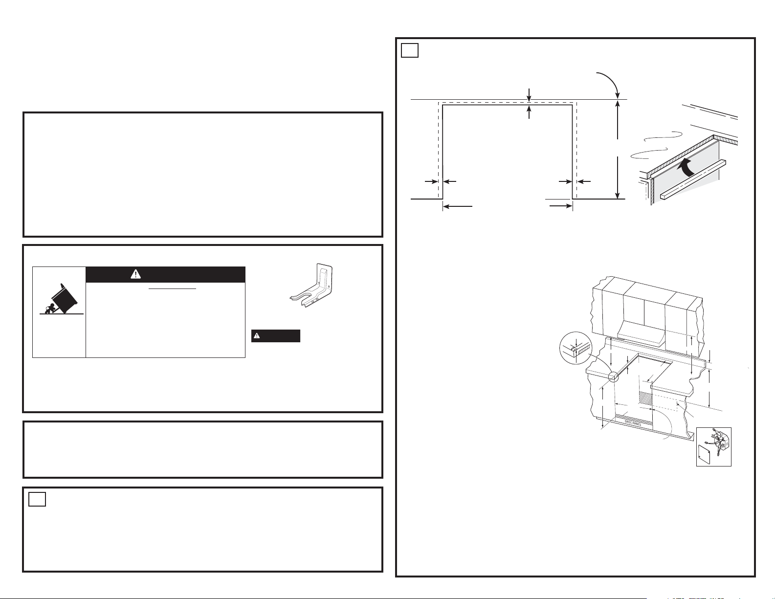
PREPARING THE OPENING (FOR INDOOR USE ONLY)
2
See the Illustrations for all rough dimensions. The range may be placed with 0” clearance at the
side cabinet.
9/16” min.
flat
26-1/4” smooth cut
3/8” min.
flat
9/16” min.
flat
Wall
25”
typically
Range support
Countertop
Brace
Countertop thickness 1-1/2” min. is required to support the product. Countertop width 1-1/2” min. is
required to properly support the 3/4” anti-tip screw.
Braces must be installed between the underside of the countertop and the cabinet if required to
obtain 1-1/2” minimum thickness (each side)
Make sure the wall coverings, counters and cabinets around the oven can withstand the heat (up to
200°F [93.3°C]) generated by the oven.
This range is designed to hang from
the counter top. It does not rest on the
cabinet. The range must not be installed
on a floor or sub structure (2” x 4”
support)
•
Allow 30” minimum clearance between
surface units and bottom of unprotected
wood or metal cabinet, or allow a 24”
minimum when bottom of wood or metal
cabinet is protected by no less than 1/4”
thick flame retardant millboard covered
with not less than No 28 MSG sheet
metal, (.015”), .015” thick stainless steel,
13/32”
TRIM SECTION FOR
COUNTERTOP WITH
POST FORMED OR
RAISED FRONT EDGE
18” Min.
28-7/16”
*
21-3/4” CABINET
FACE TO REAR OF
CUT-OUT
27”
BETWEEN
CABINETS
MOULDING MAY BE FITTED TO
THE OVEN TRIM FOR A MORE
CUSTOM APPEARANCE
30” MIN.
4” MAX.
28-1/2”
MIN.
JUNCTION BOX LOCATION
(BOX MUST NOT EXTEND MORE THAN
3” OFF THE PLANE OF THE WALL)
.024” aluminium or .020” copper.
•
This appliance has been approved for 0”
spacing to adjacent surfaces above the cooktop. However, a 6” minimum spacing to surfaces less
than 15” above the cooktop and adjacent cabinet is recommended to reduce exposure to steam,
grease splatter and heat.
• To reduce the risk of burns or fire when reaching over hot surface elements, cabinet storage space
above the cooktop should be avoided. If cabinet storage space is to be provided above the cooktop, the risk can be reduced by installing a range hood that projects at least 5” beyond the front of
the cabinets. Cabinets installed above the cooktop must be no deeper than 16”.
Locate a wiring junction box at the rear of the cutout. The dimension from the top of the wiring junction box to the countertop must be a minimum of 28-1/2”. The box must not extend more that 3” off
the plane of a wall. The junction box must be located where it will allow considerable slack in the
range conduit, so that the range can be pulled for servicing if necessary.
ELECTRICAL REQUIREMENTS
3
WARNING
• This appliance must be properly grounded.
• Do not use an extension cord.
• Before installing range, switch power off at the service panel and lock the service disconnecting
means
cannot be locked, securely fasten a prominent warning device, such as a tag, to the service panel.
Failure to follow these instructions may result in serious injury or death.
WARNING
Improper connection of aluminum house wiring to copper leads can result in an electrical or fire hazard.
If residence leads are aluminum, use only connectors designed for joining copper to aluminum and
follow the manufacturer’s recommended procedure closely. Failure to do so may result in serious injury
or death.
We recommend you have the electrical wiring and hookup of your appliance connected by a
qualified electrician. After installation, have the electrician show you how to disconnect power from
the appliance.
You must use a single-phase, 120/208 VAC or 120/240 VAC, 60 Hertz electrical system.
Effective January 1, 1996, the National Electrical Code requires that new construction (not existing)
utilize a four-conductor connection to an electric oven. When installing an electric oven in new
construction, a mobile home, recreational vehicle or an area where local codes prohibit grounding
through the neutral conductor, refer to the section on four-conductor branch circuit connections.
Check with your local utilities for electrical codes which apply
in your area. Failure to wire your oven according to governing
codes could result in a hazardous condition. If there are no
local codes, your oven must be wired and fused to meet
the National Electrical Code, NFPA No. 70 – latest edition,
available from the National Fire Protection Association.
Rating plate is located on oven front frame and is visible
when oven door is open.
This appliance must be supplied with the proper voltage and
frequency, and connected to an individual, properly grounded,
40 amp (minimum) branch circuit protected by a circuit
breaker or time-delay fuse.
DO NOT shorten the flexible conduit. The conduit strain relief
clamp must be securely attached to the junction box and the flexible conduit must be securely
attached to the clamp. If the flexible conduit will not fit within the clamp, do not install the oven until
a clamp of the proper size is obtained.
The 3 power leads supplied with this appliance are suitable for connection to heavier gauge
household wiring. The insulation of these 3 leads is rated for temperatures much higher than
the temperature rating of the household wiring. The current-carrying capacity of the conductor is
governed by the wire gauge and the temperature rating of the insulation around the wire.
Electric Shock Hazard
to prevent power from being switched on accidentally. When the disconnection means
Fire Hazard
Rating Plate Location
4
ELECTRICAL REQUIREMENTS
WARNING
• This appliance must be properly grounded.
• Do not use an extension cord.
• Before installing range, switch power off at the service panel and lock the service
disconnecting means to prevent power from being switched on accidentally. When the
disconnection means cannot be locked, securely fasten a prominent warning device, such
as a tag, to the service panel.
Failure to follow these instructions may result in serious injury or death.
WARNING
Improper connection of aluminum house wiring to copper leads can result in an electrical
or fire hazard. If residence leads are aluminum, use only connectors designed for joining
copper to aluminum and follow the manufacturer’s recommended procedure closely. Failure
to do so may result in serious injury or death. We recommend you have the electrical wiring
and hookup of your range connected by a qualified electrician. After installation, have the
electrician show you how to disconnect power from the range.
We recommend you have the electrical wiring and hookup of the appliance connected by a qualified
electrician. After installation, have the electrician show you how to disconnect power from the appliance.
You must use a single-phase, 120/208 VAC or 120/240 VAC, 60 Hertz electrical system.
Effective January 1, 1996, the National Electrical Code requires that new construction (not existing)
utilize a four-conductor connection to an electric oven. When installing an electric oven in new
construction, a mobile home, recreational vehicle or area where local codes prohibit grounding
through the neutral conductor, refer to the section on four-conductor branch circuit connections.
Check with your local utilities for electrical codes which apply in your area. Failure to wire your oven
according to governing code could result in a hazardous condition. If there are no local codes, your
oven must be wired and fused to meet the National Electrical Code, NFPA No. 70-latest edition,
available from the National Fire Protection Association.
Rating plate is located on oven front frame and is visible when oven door is open.
This appliance must supplied be with the proper voltage and frequency, and connected to an individual,
properly grounded, 40 amp (minimum) branch circuit protected by a circuit breaker or time-delay fuse.
DO NOT shorten the flexible conduit. The conduit strain relief clamp must be securely attached to
the junction box and the flexible conduit must securely attached to the clamp. If the flexible conduit
will not fit within the clamp, do not install the oven until a clamp of the proper size is obtained.
The 3 power leads supplied with this appliance are suitable for connection to heavier gauge
household wiring. The insulation of these 3 leads is rated for temperatures much higher than
the temperature rating of the household wiring. The current-carrying capacity of the conductor is
governed by the wire gauge and the temperature rating of the insulation around the wire.
Electric Shock Hazard
Fire Hazard
4
ELECTRICAL REQUIREMENTS (Cont.)
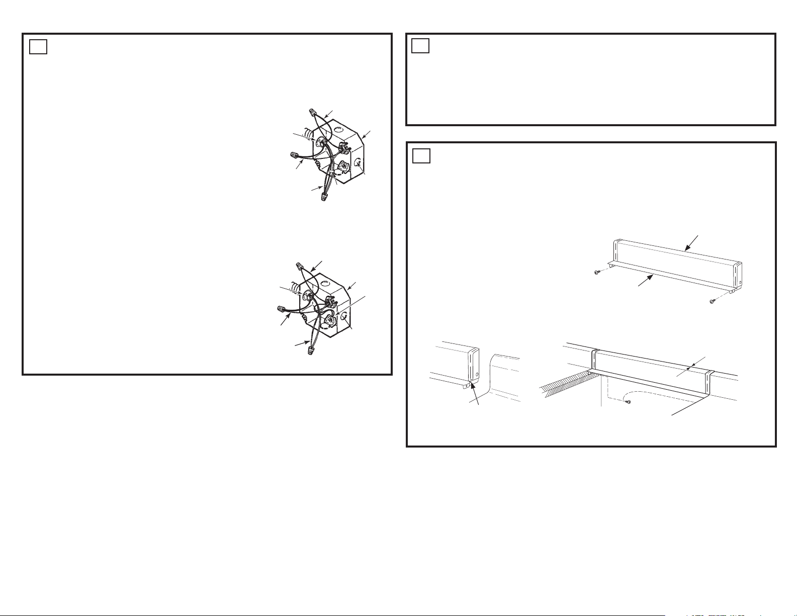
MAKE ELECTRICAL CONNECTIONS
Place the unit on a platform or table even with the cutout opening. The platform must support
200 lbs. (91 kg). Connect the flexible conduit to the electrical junction box as follows:
THREE-CONDUCTOR BRANCH CIRCUIT CONNECTION
NOTE: If residence leads are aluminum conductors, see
WARNING in section 4A, Electrical Requirements.
When connecting to a three-conductor branch circuit, if local codes
permit:
1. Connect the oven ground conductor along with the neutral
Range
conduit
snaps
into box
Black
(white) lead to the branch circuit neutral (white or gray in color),
using a wire nut.
2. Connect the oven red lead to the branch circuit red lead, and the
oven black lead to the branch circuit black lead in accordance
with local codes, using wire nuts.
3. Install proper strain relief clamp.
4. Install junction box cover.
Red
Ground
and neutral
wires (white)
Tape or
Crimp
Neutral wire
connection
FOUR-CONDUCTOR BRANCH CIRCUIT CONNECTION
NOTE: If residence leads or ground are aluminum conductors, see WARNING in section 4,
Electrical Requirements.
When connecting to a four-conductor branch circuit, if local codes permit:
1. Free the neutral (white) lead from being restrained to any
other wires. If necessary, cut the neutral (white) lead and
then re-strip it to expose the proper length of conductor.
2. Attach the appliance grounding lead (green or bare copper)
Range conduit
snaps into box
Black
Branch
circuit
in accordance with local codes.
3. Connect the oven neutral (white) lead to the branch circuit
neutral (white or gray) in accordance with local codes,
using a wire nut.
4. Connect the oven red lead to the branch circuit red lead
and the oven black lead to the branch circuit black lead in
ac cor dance with local codes, using wire nuts.
Red
White
Alternate
knockout
5. Install proper strain relief clamp.
6. Install junction box cover.
Branch
circuit
Alternate
knockout
Ground
wires
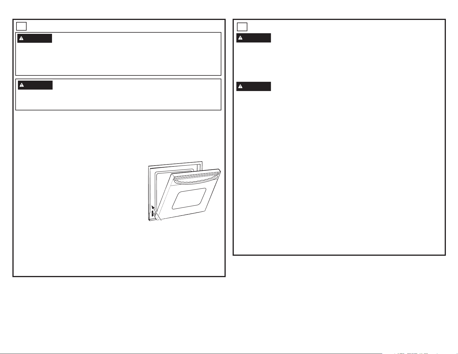
5
CHECK FOR PROPER INSTALLATION OF ANTI-TIP
SCREWS
• Raise lift-up cooktop and support it with cooktop support rod so anti tip screws are visible. (see
Section 7)
• Lower the oven door and gently apply a medium force to the inside of the door at the handle end.
• Properly installed screws will prevent any movement of the range when force is applied to the
door. If movement occurs, refer to “Mounting the range in the opening” section.
WHEN INSTALLING RANGE IN COUNTERTOP WHICH IS
6
CUT OUT TO THE WALL
If you have an existing 27” wide cutout that goes all the way to the wall, you may want to buy a
backsplash kit for your range. Order Kit JX27RWH (White) or Kit JX27RBK (Black). This kit will fill in
the space between the back of the range and the wall.
BACKSPLASH KIT FOR 27” DROP-IN RANGES
This kit contains:
1 Backsplash
2 Screws
1 Maintop Filler
2 Wood Screws
NOTE: The backsplash attaches to the
counter. The range slides into position after the
backsplash is in place.
Follow the instructions packed with the backsplach kit.
Filler
Backsplash with End Caps
Screw
Possible Gap May Occur
31-10830-3 10-20 GEA
Trim for any interference
with postformed backsplash on countertop.
Wood Screws Provided
 Loading...