

Page 1

Document Information for:
LU44246ADW
Type
Name
Revision
State
Drawing Print
LU44246ADW
3
Release
ECO 2086536
Description
Originator
DPX-NT,MD Service Manual
212027348_jennifer_lynn_pakter
File List
1. LU44246ADW_s1_r3.pdf
Approval Information
Person Action Date and Time
212018997_connie_c_hottman Approved 05/20/2010 2:26:30 PM GMT
212027348_jennifer_lynn_pakter Approved 05/11/2010 7:39:55 PM GMT
This page is generated automatically by the GEHC MyWorkshop System.
Printed documents are for Reference Only and may be out-of-date.
Check the database to ensure you have the correct revision.
State: RELEASE - Document is released and under formal Change Control. Changes are subject to the ECR/ECO Process.
See the GEHC Myworkshop System to determine the status of this document.
Approved Document - LU44246ADW_r3.pdf Page 1 of 142
Page 2

GE Healthcare
DPX-NT and MD+ Service Manual
Date: Mar 2010
Part No.: LU44246
Revision 3
ECO 2086536
Headquarters
GE Medical Systems Lunar
3030 Ohmeda Drive
Madison, WI 53718-6704
USA
+1 (800) 437-1171
Europe
GE Medical Systems IT GmbH
Munzinger Strasse 3-5
D-79111 Freiburg
Germany
+49-212-2802 -652
+49-761-4543 -233 (Fax)
State: RELEASE - Document is released and under formal Change Control. Changes are subject to the ECR/ECO Process.
See the GEHC Myworkshop System to determine the status of this document.
© 2009 by GE Healthcare
Asia/Pacific
4-7-127 Asahigaoka
Hino-shi, Tokyo 191-8503
Japan
+81-42-585-5111
+81-42-585-3077 (Fax)
Germany
Beethoven Str. 239
D-42655 Solingen
Germany
+49-212-2802-0
+49-212-2802-390 (Fax)
www.gehealthcare.com
China
No. 19 Changjiang Road
Wuxi, Jiangsu, 214028
P.R.C.
+86-510-85225888
+86-510-85226688 (Fax)
France
GE Healthcare Lunar
11 Avenue Morane
Saulnier
78457 Velizy
France
+33-1-34-49-5365
+33-1-34-49-5406 (Fax)
Approved Document - LU44246ADW_r3.pdf Page 2 of 142
Page 3

This page left blank intentionally.
Page 2 of 141
DPX-NT/MD+ Service Manual (Rev. 3 - 2010)
State: RELEASE - Document is released and under formal Change Control. Changes are subject to the ECR/ECO Process.
See the GEHC Myworkshop System to determine the status of this document.
Approved Document - LU44246ADW_r3.pdf Page 3 of 142
Page 4

Revision History
DPX-NT/MD+ Service Manual (Rev. 3 - 2010)
Page 3 of 141
Revision Date Author Description
3 Mar 2010 Jennifer Pakter 1. Updated English Only Disclaimer (added
languages since last revision).
2. Added detailed test work instructions to
Section 5.6.
3. Removed test grid and referenced
LUSE0002 in its place.
2 Dec 2010 Jennifer Pakter 4. Updated English Only Disclaimer (added
languages since last revision).
5. Updated Sections 1.0 and Chapter 5 to
comply with MD.
6. Added NT/MD+ revision information to
Section 2.0
7. Added OMD information to Section 2.4.1
8. Removed system labels
9. Updated Appendix
1 Jun 2009 Jennifer Pakter 1. Updated contact information on cover due
to facility moves
2. Added English Only disclaimer in multiple
languages
3. Updated labels
4. Added appendix that lists associated
service documentation.
Previous revisions were under part number
LU8392 last revision C approved on CO L6631
in Oracle Engineering. Revision History was
not recorded in document until Rev. 1.
State: RELEASE - Document is released and under formal Change Control. Changes are subject to the ECR/ECO Process.
See the GEHC Myworkshop System to determine the status of this document.
Approved Document - LU44246ADW_r3.pdf Page 4 of 142
Page 5

This page left blank intentionally.
Page 4 of 141
DPX-NT/MD+ Service Manual (Rev. 3 - 2010)
State: RELEASE - Document is released and under formal Change Control. Changes are subject to the ECR/ECO Process.
See the GEHC Myworkshop System to determine the status of this document.
Approved Document - LU44246ADW_r3.pdf Page 5 of 142
Page 6

This document contains confidential or proprietary information of GE Healthcare.
䄺
ᤞܫ
ᤞܫ
DPX-NT/MD+ Service Manual (Rev. 3 - 2010)
Page 5 of 141
Neither the document nor the information is to be reproduced, distributed, used
or disclosed, either in whole or in part, except as specifically authorized by GE
Healthcare.
GE Healthcare makes no warranty of any kind with regard to this material, and
shall not be held liable for errors contained herein or for incidental or
consequential damages in connection with the furnishings or use of this manual.
Read through this manual thoroughly before attempting to service any
components. Unauthorized service may void system warranties or service
contracts. Consult the GE Healthcare Customer Support Department prior to
attempting any servicing.
WARNING
(EN)
ɉɊȿȾɍɉɊȿɀȾȿɇɂȿ
(BG)
(ZH-CN)
(ZH-HK)
(ZH-TW)
This service manual is available in English only.
x If a customer's service provider requires a language other than english, it is the
customer's responsibility to provide translation services.
x Do not attempt to service the equipment unless this service manual has been
consulted and is understood.
x Failure to heed this warning may result in injury to the service provider, operator
or patient from electric shock, mechanical or other hazards.
Ɍɨɜɚ ɭɩɴɬɜɚɧɟ ɡɚ ɪɚɛɨɬɚ ɟ ɧɚɥɢɱɧɨ ɫɚɦɨ ɧɚ ɚɧɝɥɢɣɫɤɢ ɟɡɢɤ.
x Ⱥɤɨ ɞɨɫɬɚɜɱɢɤɴɬ ɧɚ ɭɫɥɭɝɚɬɚ ɧɚ ɤɥɢɟɧɬɚ ɢɡɢɫɤɚ ɞɪɭɝ ɟɡɢɤ, ɡɚɞɴɥɠɟɧɢɟ ɧɚ
ɤɥɢɟɧɬɚ ɟ ɞɚ ɨɫɢɝɭɪɢ ɩɪɟɜɨɞ.
x ɇɟ ɢɡɩɨɥɡɜɚɣɬɟ ɨɛɨɪɭɞɜɚɧɟɬɨ, ɩɪɟɞɢ ɞɚ ɫɬɟ ɫɟ ɤɨɧɫɭɥɬɢɪɚɥɢ ɢ ɪɚɡɛɪɚɥɢ
ɭɩɴɬɜɚɧɟɬɨ ɡɚ ɪɚɛɨɬɚ.
x ɇɟɫɩɚɡɜɚɧɟɬɨ ɧɚ ɬɨɜɚ ɩɪɟɞɭɩɪɟɠɞɟɧɢɟ ɦɨɠɟ ɞɚ ɞɨɜɟɞɟ ɞɨ ɧɚɪɚɧɹɜɚɧɟ ɧɚ
ɞɨɫɬɚɜɱɢɤɚ ɧɚ ɭɫɥɭɝɚɬɚ, ɨɩɟɪɚɬɨɪɚ ɢɥɢ ɩɚɰɢɟɧɬa ɜ ɪɟɡɭɥɬɚɬ ɧɚ ɬɨɤɨɜ ɭɞɚɪ,
ɦɟɯɚɧɢɱɧɚ ɢɥɢ ɞɪɭɝɚ ɨɩɚɫɧɨɫɬ.
ᴀ㓈ׂݠҙᦤկ㣅᭛⠜ᴀDŽ
x བᵰᅶ᠋ⱘ㓈ׂ᳡ࡵҎ䳔㽕䴲㣅᭛⠜ᴀˈ߭ᅶ᠋䳔㞾㸠ᦤկ㗏䆥᳡ࡵDŽ
x 䆺㒚䯙䇏ᅠܼ⧚㾷ᴀ㓈ׂݠПࠡˈϡᕫ䖯㸠㓈ׂDŽ
x ᗑ⬹ᴀ䄺ৃ㛑ᇍ㓈ׂ᳡ࡵҎǃ᪡Ҏᙷ㗙䗴៤⬉ߏǃᴎẄӸᆇ݊Ҫᔶ
ᓣⱘӸᆇDŽ
ءࣚ೭֫םႛ༼ࠎ֮ءΖ
x ଣૉড়֪ࣚ೭ࠎᚨᏁ֮א؆հࣚ೭֫םΔড়֪ڶຂٚ༼ࠎࣚ೭Ζ
x ೈբᔹءࣚ೭֫ם֗ࣔػࠡփ୲Δܡঞ֊֎ቫᇢፂଥໂΖ
x լᙅൕءᤞܫࢨᄎחࣚ೭ࠎᚨΕጻࠎᚨࢨఐԳ࠹ࠩᤛሽΕᖲඳࢤࢨࠡה
ٲᙠΖ
ءፂଥ֫םႛڶ֮Ζ
x ૉড়֪ፂଥᐗᏁ֮א؆ߢΔᚨطড়֪۞۩༼ࠎࣚ೭Ζ
x ᓮ֎ᇢቹፂଥءໂΔೈ ൞բᔹࠀᛵᇞءፂଥ֫םΖ
x ૉآఎრءᤞܫΔױ౨ᖄીፂଥᐗΕᖙ܂ࢨఐ൛ڂᤛሽΕᖲඳࢨࠡהٲᙠۖ
࠹႞Ζ
State: RELEASE - Document is released and under formal Change Control. Changes are subject to the ECR/ECO Process.
See the GEHC Myworkshop System to determine the status of this document.
Approved Document - LU44246ADW_r3.pdf Page 6 of 142
Page 7

READ THIS FIRST
DPX-NT/MD+ Service Manual (Rev. 3 - 2010)
Page 11 of 141
Using This Manual
A person who will be performing service work on the DPX-NT / MD+ should use this
manual in the following manner:
Read the Safety and Overview Chapters to familiarize yourself with the scanner
as a whole and with the genera lfunction of the circuit boards.
Chapter 3 should be understood completely as it explains the Diagnostics
Software (built in – requires a password for access).
The Chapter 4 and Chapter 5 contain common procedures and troubleshooting
information and can be read as needed, but are good sources of information.
When a problem arises, Chapter 4 should be referenced. Check the table of
contents for Chapter 4 to see if the problem being experienced is described. If
so, refer to the appropriate page. If not, try to generalize the problem (e.g. the
Detector is repeatedly running into the front of the scanner and reversing and
then running back into the front of the scanner. This is a mechanical problem in
general, specifically with Transverse Mechanics, check that subsection of
Chapter 4 for the subsystem experiencing the fault.
This manual commonly references other Sections and pages of the manual as
needed, so often procedures in the Chapter 5 and the Appendix are referred to
as ways to solve problems described in Chapter 4.
State: RELEASE - Document is released and under formal Change Control. Changes are subject to the ECR/ECO Process.
See the GEHC Myworkshop System to determine the status of this document.
Approved Document - LU44246ADW_r3.pdf Page 12 of 142
Page 8

This page left blank intentionally.
Page 12 of 141
DPX-NT/MD+ Service Manual (Rev. 3 - 2010)
State: RELEASE - Document is released and under formal Change Control. Changes are subject to the ECR/ECO Process.
See the GEHC Myworkshop System to determine the status of this document.
Approved Document - LU44246ADW_r3.pdf Page 13 of 142
Page 9

Table of Contents
DPX-NT/MD+ Service Manual (Rev. 3 - 2010)
Page 13 of 141
Chapter 1: Safety 15
1.0 General Safety 17
1.1 Symbols and labels found on the DPX-NT / MD+ 18
1.2 Emergency Stop Button 22
1.3 Laser Exposure 23
1.4 Shutter Indicator 24
1.5 Cautions, Warnings, and Notes 24
1.6 Safety Concerns 25
1.7 Scatter Radiation 26
1.8 Controlling Computer and Accessories 29
1.9 Peripheral configurations 29
Chapter 2: System Overview 33
2.0 DPX-NT / MD+ System 37
2.1 Electronics 38
2.2 DPX-NT / MD+ Block Diagrams 40
2.3 DPX-NT / MD+ Fusing 43
2.4 Combined Single Board Controller cSBC 43
2.5 X-ray Source 61
2.6 Display Panel 62
2.7 High Voltage Power Supplies 63
2.8 D-MAX Board (DPX-NT (A) ONLY) 63
2.9 XORB Board (DPX-NT (A) ONLY) 63
2.10 Detector Sub System 64
2.11 X-Ray Collimator Subsystem 64
2.12 DPX-NT / MD+ Specifications 65
2.13 Secondary Calibration / Daily QA 76
Chapter 3: Service Software 81
3.0 Diagnostic Software 83
3.1 The Tools Menu 84
State: RELEASE - Document is released and under formal Change Control. Changes are subject to the ECR/ECO Process.
See the GEHC Myworkshop System to determine the status of this document.
Approved Document - LU44246ADW_r3.pdf Page 14 of 142
Page 10

3.2 Tools / Diagnostics Menu 85
Page 14 of 141
DPX-NT/MD+ Service Manual (Rev. 3 - 2010)
3.3 Diagnostic Scan Modes 88
3.4 Error Log 88
3.5 Service Options 93
Chapter 4: Troubleshooting 95
4.0 Diagnostic Failure Codes 97
4.1 Transverse Motion failure 97
4.2 Longitudinal Motion failure 100
4.3 Failure of the DC Power Supply 104
4.4 Emergency Stop Button 104
4.5 Tube Head Thermostat 105
4.6 Communication Error 105
4.7 Other Diagnostic Failure Codes 105
4.8 Failing Quality Assurance Test 106
4.9 Reference Counts 109
4.10 Arcing 112
4.11 Imaging Problems 114
4.12 Failing Alignment Test Results 116
4.13 Indicator Failures 118
4.14 Communications Failures 120
4.15 Viewing Quality Assurance Trends 120
4.16 MAX Board Troubleshooting 121
4.17 OMI/OMD Board Troubleshooting 122
4.18 SBC Troubleshooting 122
4.19 XORB Troubleshooting 123
Chapter 5: Service Procedures 125
5.0 Reloading LUNAR Software 127
5.1 Peaking the Detector 127
5.2 Tube Head Replacement 128
5.3 Lower Cable Bundle Replacement 129
5.4 Upper Cable Bundle Replacement 132
5.5 Tube Head Control Cable Replacement 134
5.6 Tests to Perform after Service 137
Appendix: Associated Service Documentation 141
State: RELEASE - Document is released and under formal Change Control. Changes are subject to the ECR/ECO Process.
See the GEHC Myworkshop System to determine the status of this document.
Approved Document - LU44246ADW_r3.pdf Page 15 of 142
Page 11

1
DPX-NT/MD+ Service Manual (Rev. 3 - 2010)
Page 15 of 141
Safety
This chapter highlights safety devices and features a Service
Engineer should know before servicing a DPX-NT / MD+
system.
Chapter Contents:
1.0 General Safety
1.1 Symbols and labels found on the DPX-NT / MD+
1.1.1 Symbols
1.1.2 Labels
1.2 Emergency Stop Button
1.3 Laser Exposure
1.4 Shutter Indicator
1.5 Cautions, Warnings, and Notes
1.5.1 Caution Statements
1.5.2 Warning Statements
1.5.3 Note Statements
1.6 Safety Concerns
1.7 Scatter Radiation
1.8 Controlling Computer and Accessories
1.8.1 Electrical Safety
1.9 Peripheral configurations
1.9.1 Standard room configuration
1.9.2 Small room configuration
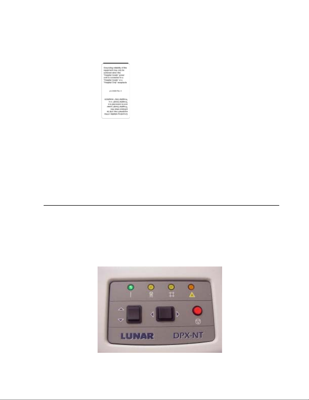
Figure 1-1. The DPX-NT / MD+ Display Panel
Figure 1-2. Laser Warning Label (All systems except Canada)
Figure 1-3. Laser Warning Label (Canadian Systems only)
Figure 1-4. Laser Warning Symbol (on display panel)
Figure 1-5. Source (x-rays) off - Shutter closed (green)
Figure 1-6. Source (x-rays) on - Shutter open (yellow)
Figure 1-7. Potential Pinch Points on the DPX-NT / MD+
Figure 1-8. DPX-NT Iso-Dose Diagram
Figure 1-9. DPX-MD+ Iso-Dose Diagram
State: RELEASE - Document is released and under formal Change Control. Changes are subject to the ECR/ECO Process.
See the GEHC Myworkshop System to determine the status of this document.
Approved Document - LU44246ADW_r3.pdf Page 16 of 142
Page 12

This page left blank intentionally.
Page 16 of 141
DPX-NT/MD+ Service Manual (Rev. 3 - 2010)
State: RELEASE - Document is released and under formal Change Control. Changes are subject to the ECR/ECO Process.
See the GEHC Myworkshop System to determine the status of this document.
Approved Document - LU44246ADW_r3.pdf Page 17 of 142
Page 13

1.0 General Safety
DPX-NT/MD+ Service Manual (Rev. 3 - 2010)
Page 17 of 141
x DO NOT attempt to service the DPX-NT / MD+ without first reading
this manual.
x DO NOT attempt any repairs without prior instructions from
authorized LUNAR personnel.
x In order to maintain electrical safety and electromagnetic
compatibility, the Lunar DPX-NT / MD+ is only to be connected to a
computer, printer, and peripherals that meet IEC requirements for
safety, such as IEC 950/ EN 60950 - “Safety of information
technology equipment, including electrical business equipment” and
IEC 601-1-2 - “Medical electrical equipment”, Part 1: General
requirements for safety, 2. Collateral Standard: Electromagnetic
compatibility - Requirements and tests.
x Ionizing Radiation: Exposure: When power is applied, this
equipment may generate ionizing radiation. Take precautions that no
part of the body passes through the x-ray beam when the equipment
is energized. Avoid scatter radiation during warm-up and testing by
maintaining a safe distance from the x-ray beam. See the Safety and
Specification manual for equipment appropriate distance and other
precautions regarding ionizing radiation. All operators must be
properly trained regarding ionizing radiation and take adequate steps
to protect against injury.
x Electric Shock: This equipment contains high voltages. When the
tabletop/panels/ shrouds are removed, visually confirm that power
cord is unplugged and remains unplugged until power is required to
complete the procedure. When servicing while energized, take
precautions to prevent electric shock.
x Moving Parts and Pinch Points: Avoid moving parts and pinch
points (e.g. belt/pulley, arm/back rail, green wheels/rail).
x Sharp Edges: Take precautions to prevent injury from contact with
component edges (e.g. OMI/OMD wheel, arm slot cover).
x Hot Surfaces: Keep hands clear or allow components to cool before
servicing. (e.g. stepper motors, hard drives, power supplies and
microprocessors).
x Heavy Lifting: Obtain help lifting or moving any object weighing over
EHS limits. Ask for assistance when maneuvering awkward objects
(e.g. tabletop).
x Laser Radiation: Do not stare into the laser beam at any time. The
reflection from the tabletop or shutter/collimator assembly is sufficient
to determine if the laser is on.
x Follow appropriate Lockout/Tagout procedures as described in
MyLearning training course GEMS-EHS-LOTOAth.
x Wear appropriate PPE (Personal Protective Equipment) while
servicing the equipment, e.g. eye protection and steel-toe/compositetoe shoes.
State: RELEASE - Document is released and under formal Change Control. Changes are subject to the ECR/ECO Process.
See the GEHC Myworkshop System to determine the status of this document.
Approved Document - LU44246ADW_r3.pdf Page 18 of 142
Page 14
1.1 Symbols and labels found on the DPX-NT /
Page 18 of 141
DPX-NT/MD+ Service Manual (Rev. 3 - 2010)
MD+
1.1.1 Symbols
x The following symbols are found on the DPX-NT / MD+, in the
Operators manual, and in the Service Manual.
Attention: contains important safety information such as the
location of a pinch point.
Emergency Stop Button: shows the location of the emergency
stop button.
Power On: shows the location of the Power On indicator.
Laser On: shows the location of the Laser On indicator.
State: RELEASE - Document is released and under formal Change Control. Changes are subject to the ECR/ECO Process.
See the GEHC Myworkshop System to determine the status of this document.
Approved Document - LU44246ADW_r3.pdf Page 19 of 142
Page 15
Shutter Open:
DPX-NT/MD+ Service Manual (Rev. 3 - 2010)
Page 19 of 141
shows the location of the Shutter Open indicator.
X-ray On:
Type B Equipment:
shows the location of the X-Ray On indicator.
shows that the scanner has Type B
protection against electrical shock.
Protective Earth:
shows the location of a protective earth
terminal.
Functional Earth:
shows the location of a functional earth
terminal.
1.1.2 Labels
• The following labels are found on the DPX-NT / MD+ Scanner.
Laser Caution Label:
Shows that the scanner uses
a Class II laser.
Laser Caution Label:
State: RELEASE - Document is released and under formal Change Control. Changes are subject to the ECR/ECO Process.
See the GEHC Myworkshop System to determine the status of this document.
Approved Document - LU44246ADW_r3.pdf Page 20 of 142
Canada only
Page 16
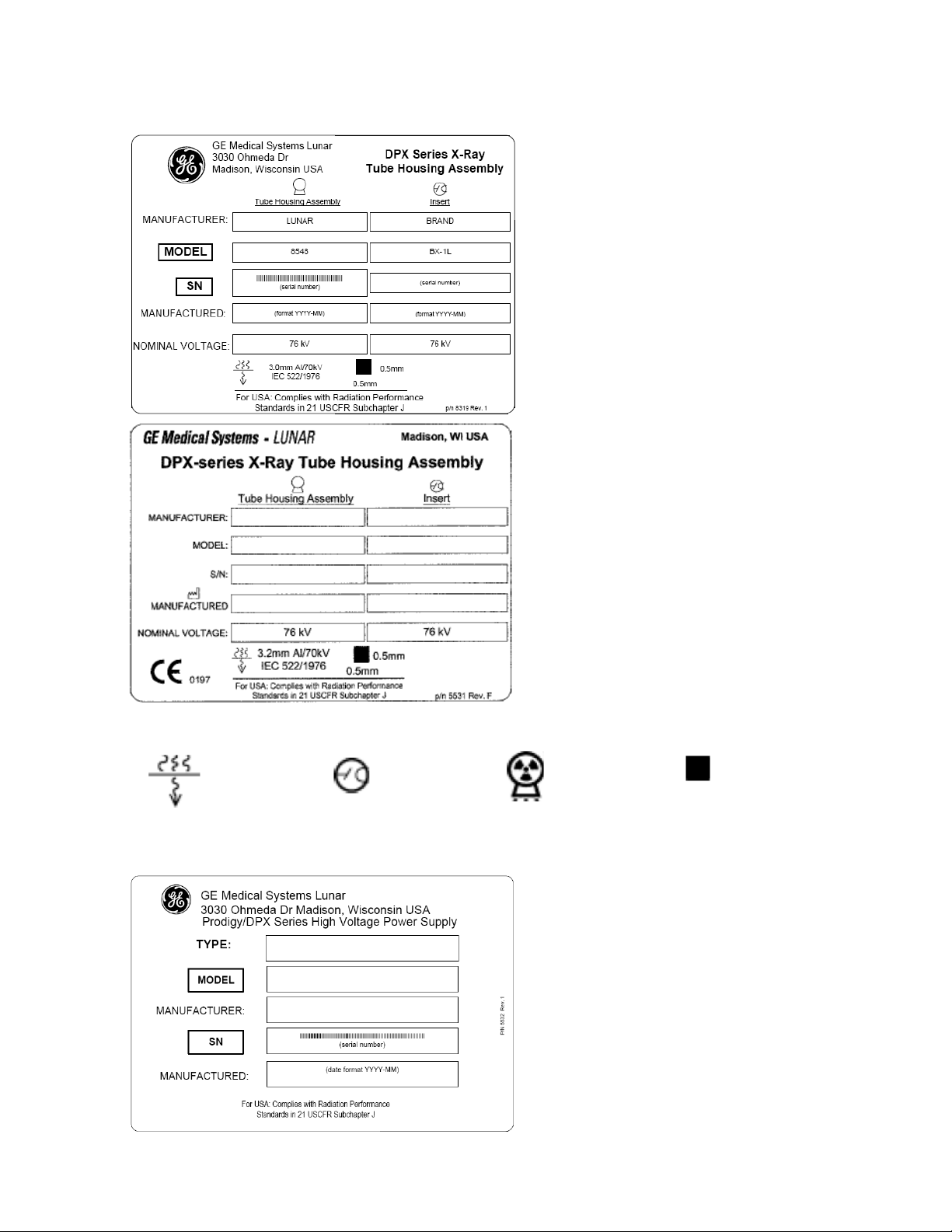
Tube Head Assembly Label (All
Page 20 of 141
DPX-NT/MD+ Service Manual (Rev. 3 - 2010)
DPX-MD+ and DPX-NT System
Number 72000 and higher): This
label gives tube head assembly and xray source characteristics information.
It is located on the tube head
assembly and the foot panel of the
scanner.
Tube Head Assembly Label (DPXNT System Number 71999 and
lower): This label gives tube head
assembly and x-ray source
characteristics information. It is
located on the tube head assembly
and the foot panel of the scanner.
A definition of each symbol on this label follows:
Inherent
Filtration
Tube
Insert
X-ray
Source
High Voltage Power Supply: This
label gives high voltage power supply
(x-ray generator) information. It is
located on the high voltage power
supply(s), and foot panel of the
scanner.
State: RELEASE - Document is released and under formal Change Control. Changes are subject to the ECR/ECO Process.
See the GEHC Myworkshop System to determine the status of this document.
Focal
Point
Approved Document - LU44246ADW_r3.pdf Page 21 of 142
Page 17
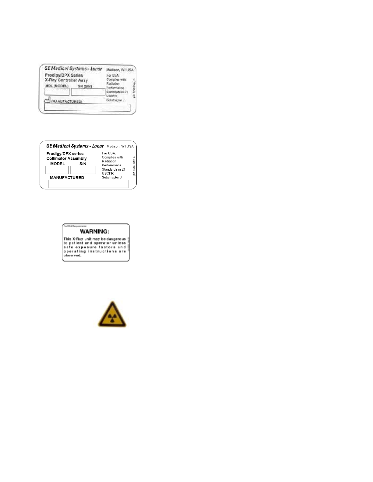
X-ray Controller: This label shows x-ray controller
DPX-NT/MD+ Service Manual (Rev. 3 - 2010)
Page 21 of 141
compliance. It is located on the foot panel of the scanner.
Collimator Assembly: This label gives collimator assembly
information. It is located on the collimator and foot panel of
the scanner.
Warning Label and Radiation Symbol: The Warning label
shows that the system uses ionizing radiation. It is found only
on systems delivered in the United States. Always obey
instructions for safe operation.
Radiation Label: This label shows that the system uses ionizing
radiation.
State: RELEASE - Document is released and under formal Change Control. Changes are subject to the ECR/ECO Process.
See the GEHC Myworkshop System to determine the status of this document.
Approved Document - LU44246ADW_r3.pdf Page 22 of 142
Page 18
Grounding Reliability Label:
Page 22 of 141
DPX-NT/MD+ Service Manual (Rev. 3 - 2010)
This label states that
grounding reliability can only be maintained when using a
“Hospital Grade” or “Hospital Only” receptacle. It is only found
on systems delivered in the United States.
Note: When replacing a certified component (x-ray controller, x-ray
tube head, collimator or high voltage power supply(s)) also
install the duplicate certified component label (supplied with
the repalcement certified component) on the foot end panel of
the scanner. The label for the new part should be palced
directly over the laber for the part it is replacing.
Refer to DXSE3001 DPX-NT / MD+ Label Replacement
Procedure (Chapter 5Appendix I - this manual) for specific
instructions.
1.2 Emergency Stop Button
• The Emergency Stop Button is located on the front of the scan arm of the
DPX-NT / MD+ scanner (see Figure 1-1). When pressed, power is
removed from the X-ray tube head, the laser, and the shutter is closed.
Power is also removed from the scan arm motors, allowing the operator/
patient to push the scan arm out of the way.
Figure 1-1. The DPX-NT / MD+ Display Panel
State: RELEASE - Document is released and under formal Change Control. Changes are subject to the ECR/ECO Process.
See the GEHC Myworkshop System to determine the status of this document.
Approved Document - LU44246ADW_r3.pdf Page 23 of 142
Page 19
1.3 Laser Exposure
DPX-NT/MD+ Service Manual (Rev. 3 - 2010)
Page 23 of 141
• The DPX-NT / MD+ is equipped with a Class II Laser device. This laser is
used for patient positioning. A Class II rating indicates a low power visible
laser that is not normally hazardous to eyesight but has the potential to
be hazardous if viewed directly for an extended period of time. Because
of this potential hazard, DO NOT stare directly into the beam while the
laser is in operation, and DO NOT allow the beam to shine directly into
the patients' eyes. No specific eye protection is required with a Class II
laser.
• A amber laser-on indicator, located on the front of the scan arm, is lit
when the laser is on. The program activates the laser during positioning
for an image acquisition. The program then turns off the laser when you
begin the scan. The emergency stop button will turn off the laser.
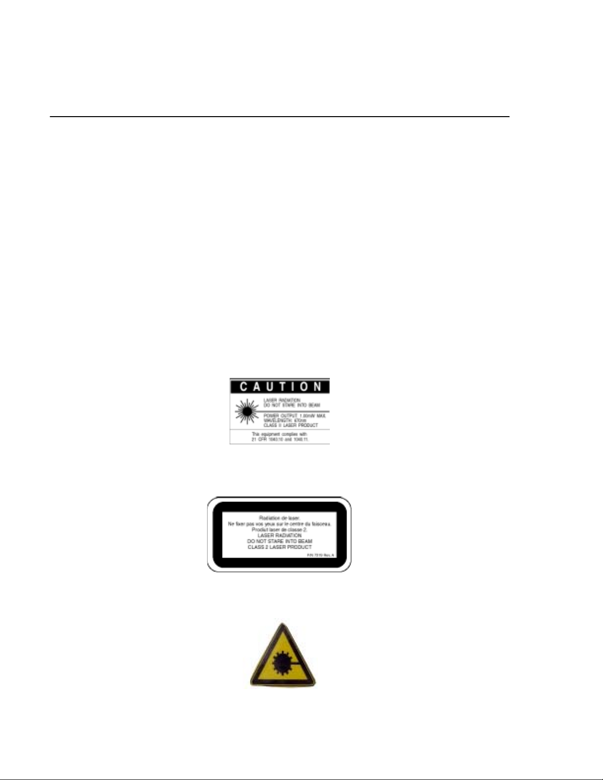
• There is a caution label (Figure 1.2) on the scan arm near the Display
Panel.
Figure 1-2. Laser Warning Label (All systems except Canada)
Figure 1-3. Laser Warning Label (Canadian Systems only)
Figure 1-4. Laser Warning Symbol (on display panel)
State: RELEASE - Document is released and under formal Change Control. Changes are subject to the ECR/ECO Process.
See the GEHC Myworkshop System to determine the status of this document.
Note: DO NOT STARE INTO THE BEAM while the laser is
operating.
Approved Document - LU44246ADW_r3.pdf Page 24 of 142
Page 20
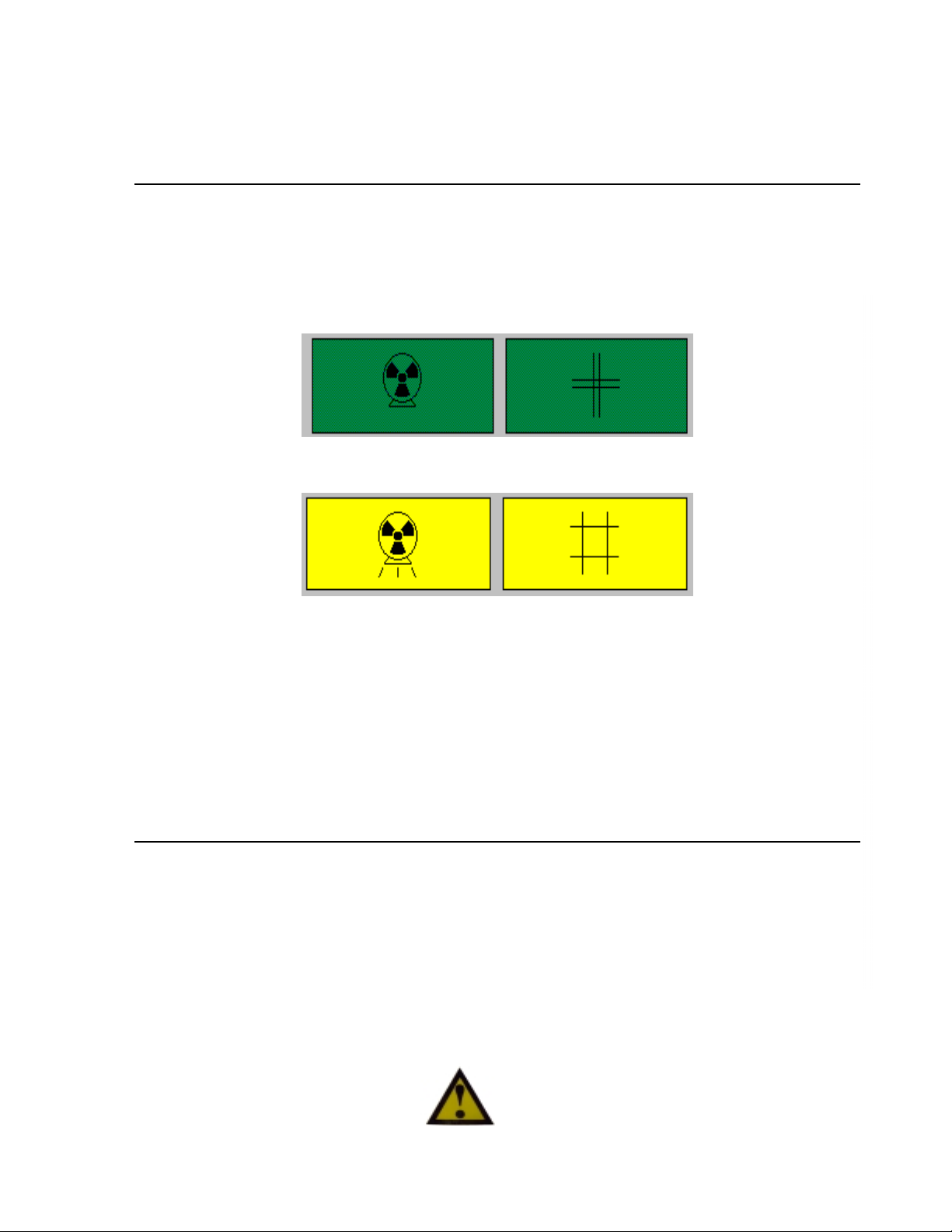
1.4 Shutter Indicator
Page 24 of 141
DPX-NT/MD+ Service Manual (Rev. 3 - 2010)
• This symbol is used to indicate an open-shutter condition in accordance
with the safety standards established by the International
Electrotechnical Commission (IEC).
Figure 1-5. Source (x-rays) off - Shutter closed (green)
Figure 1-6. Source (x-rays) on - Shutter open (yellow)
• This symbol appears near the yellow X-ray shutter-open indicator light.
The X-ray shutter-open indicator light is located on the Display Panel on
the scan arm near the front.
Note: When the x-ray on / shutter open symbol appears in literature
associated with the DPX-NT / MD+ scanner, it will be used to
indicate that the procedure being described results in an openshutter condition. During these times personnel should
exercise caution to avoid excessive exposure to the X-rays.
1.5 Cautions, Warnings, and Notes
• This manual contains warning and caution statements wherever
appropriate for your safety. The warnings and cautions used throughout
the manual are based on the safety standards established by the
International Electrotechnical Commission (IEC). In addition, the manual
uses notes to attract the reader's attention to important information.
1.5.1 Caution Statements
A caution statement reflects a condition
that, if not avoided, could cause
equipment or property damage.
State: RELEASE - Document is released and under formal Change Control. Changes are subject to the ECR/ECO Process.
See the GEHC Myworkshop System to determine the status of this document.
Approved Document - LU44246ADW_r3.pdf Page 25 of 142
Page 21
1.5.2 Warning Statements
DPX-NT/MD+ Service Manual (Rev. 3 - 2010)
Page 25 of 141
1.5.3 Note Statements
Note: This symbol turns the reader's attention to important
information which may otherwise be overlooked.
1.6 Safety Concerns
A warning statement reflects a potentially
hazardous condition that, if not avoided, could
result in serious injury.
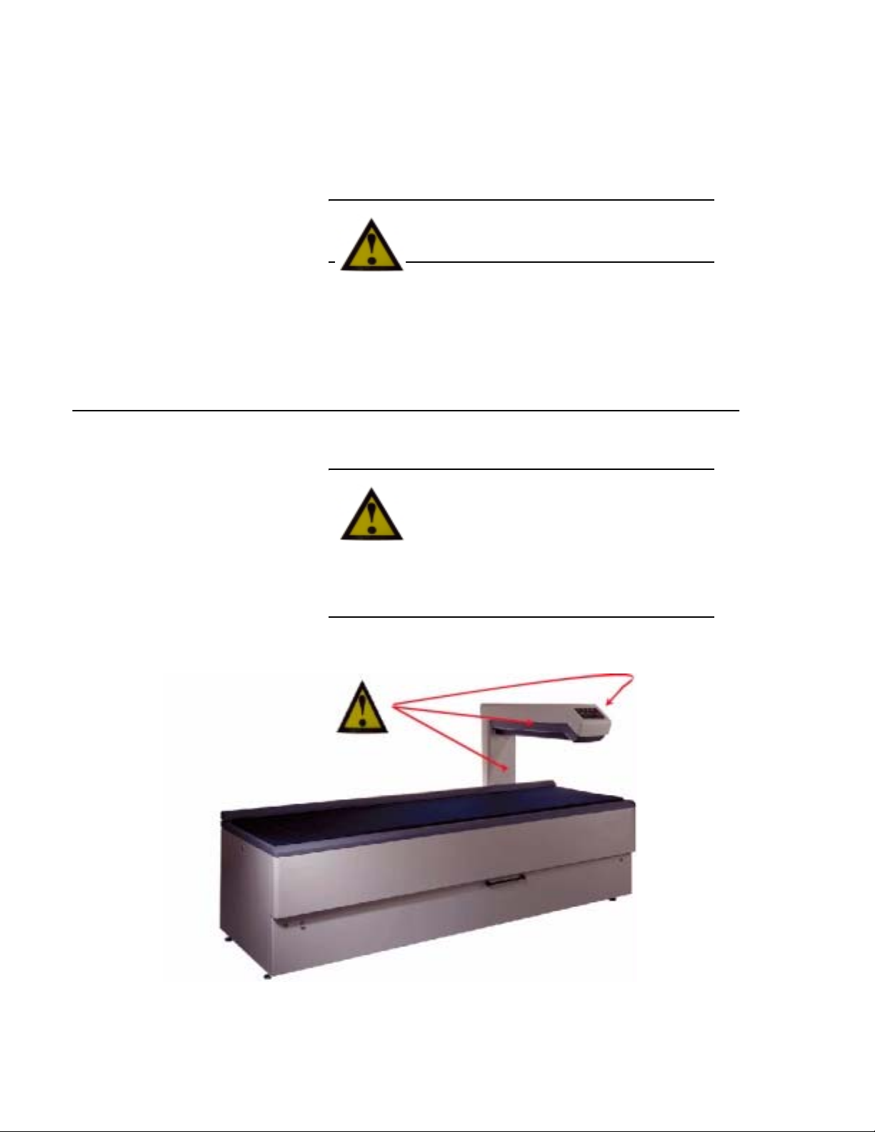
Because the DPX-NT / MD+ Densitometer
contains moving parts, there are places on the
scanner where there is a danger of pinching.
Operators should be aware of these pinch
points to avoid injury to the patient or
themselves. Labels applied at the LUNAR factory indicate the
location of the pinch points. The pinch points and their labels
are shown in the figure 1-7.
Figure 1-7. Potential Pinch Points on the DPX-NT / MD+
State: RELEASE - Document is released and under formal Change Control. Changes are subject to the ECR/ECO Process.
See the GEHC Myworkshop System to determine the status of this document.
Approved Document - LU44246ADW_r3.pdf Page 26 of 142
Page 22

DO NOT touch live components on the DC power supply - when
Page 26 of 141
DPX-NT/MD+ Service Manual (Rev. 3 - 2010)
the cover is off of the supply some components (such as the
heat sinks) are at line voltage and present a shock hazard
1.7 Scatter Radiation
• There is some scatter radiation from the DPX-NT / MD+ when it is
running. Figure 1-8 shows the radiation dosages while the scanner is
running at 1.50 mA at certain distances.
• These dosages are relatively insignificant as the allowed yearly dosage
for a person working with radiation emitting equipment is 5000 mRem.
Radiation however should be avoided when possible.
State: RELEASE - Document is released and under formal Change Control. Changes are subject to the ECR/ECO Process.
See the GEHC Myworkshop System to determine the status of this document.
Approved Document - LU44246ADW_r3.pdf Page 27 of 142
Page 23
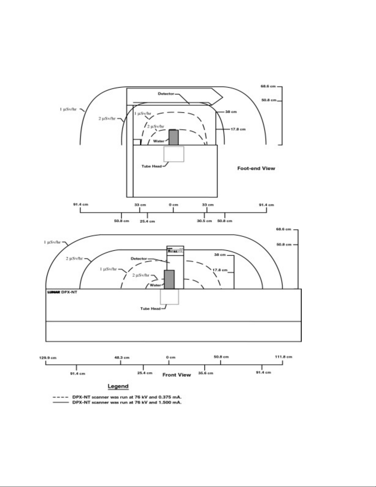
Figure 1-8. DPX-NT Iso-Dose Diagram
DPX-NT/MD+ Service Manual (Rev. 3 - 2010)
Page 27 of 141
State: RELEASE - Document is released and under formal Change Control. Changes are subject to the ECR/ECO Process.
See the GEHC Myworkshop System to determine the status of this document.
Approved Document - LU44246ADW_r3.pdf Page 28 of 142
Page 24
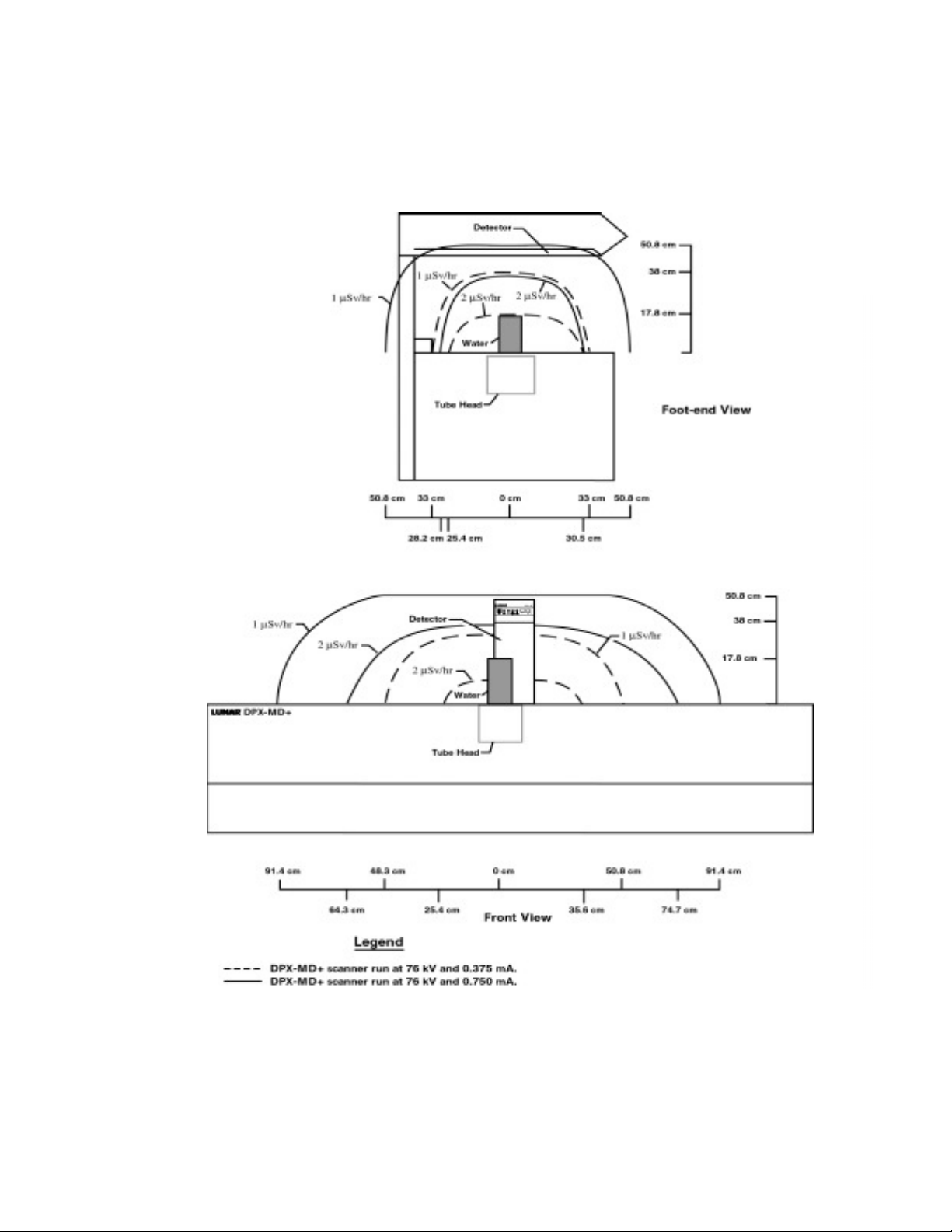
Figure 1-9. DPX-MD+ Iso-Dose Diagram
Page 28 of 141
DPX-NT/MD+ Service Manual (Rev. 3 - 2010)
State: RELEASE - Document is released and under formal Change Control. Changes are subject to the ECR/ECO Process.
See the GEHC Myworkshop System to determine the status of this document.
Approved Document - LU44246ADW_r3.pdf Page 29 of 142
Page 25
1.8 Controlling Computer and Accessories
DPX-NT/MD+ Service Manual (Rev. 3 - 2010)
Page 29 of 141
1.8.1 Electrical Safety
• IEC and UL/CSA certification
Note: Not all scanners produced are built to IEC / UL / CSA
standards - IEC / UL / CSA compliant scanners bear the
appropriate mark on the foot end panel when the scanner was
produced and shipped in its compliant form
IEC:
To maintain electrical safety, all computer equipment and accessories
connected to the scanner must meet IEC standards for safety, such as IEC
950, “Safety of information technology equipment, including electrical
business equipment,” and IEC 801-5, “EMC Surge Immunity Requirements.”
The computer and all accessories must have “CE” labels.
UL/CSA:
accessories connected to the scanner must have saftey agency approvals fo
UL/CSA and comply with these standards.
To maintain electrical safety, all computer equipment and
See Operators manual for host computer / peripheral
configurations
1.9 Peripheral configurations
The correct connection of the computer and all
peripherals is necessary to maintain electrical safety.
The signal cable of the scanner is intended only for
connection to an approved computer. Call LUNAR
Support or your LUNAR distributor before adding
peripherals.
1.9.1 Standard room configuration
State: RELEASE - Document is released and under formal Change Control. Changes are subject to the ECR/ECO Process.
See the GEHC Myworkshop System to determine the status of this document.
Approved Document - LU44246ADW_r3.pdf Page 30 of 142
Page 26
The computer, peripherals, and all other equipment
Page 30 of 141
DPX-NT/MD+ Service Manual (Rev. 3 - 2010)
must be located more than 1.83 m from the scanner.
Use an outlet strip to power the computer and all peripherals.
The outlet strip must be mounted off the floor so that it
does not touch other equipment.
0If the outlet strip was provided by LUNAR, it has a maximum output of 15A,
120VAC.
Only system-related equipment should be powered by the outlet strip.
A modem and/or network connection can be made at any time if you are using
the standard room configuration.
1.9.2 Small room configuration
The computer, peripherals, and all other equipment
must be powered with an isolating transformer if the
room is too small to maintain at least 1.83 m of
separation between the scanner and all other
equipment.
The isolation transformer supplied by LUNAR (part number 8544) has a
maximum output of 400/500VA.
Only system-related equipment should be powered by
the isolation transformer. Failure to use an isolation
transformer can cause leakage currents in excess of
100 microamperes.
State: RELEASE - Document is released and under formal Change Control. Changes are subject to the ECR/ECO Process.
See the GEHC Myworkshop System to determine the status of this document.
Approved Document - LU44246ADW_r3.pdf Page 31 of 142
Page 27

A modem and/or network connection can only be
DPX-NT/MD+ Service Manual (Rev. 3 - 2010)
Page 31 of 141
made in the small room configuration if all exposed
metal surfaces of the computer and peripherals are
out of the patient environment.
State: RELEASE - Document is released and under formal Change Control. Changes are subject to the ECR/ECO Process.
See the GEHC Myworkshop System to determine the status of this document.
Approved Document - LU44246ADW_r3.pdf Page 32 of 142
Page 28

This page left blank intentionally.
Page 32 of 141
DPX-NT/MD+ Service Manual (Rev. 3 - 2010)
State: RELEASE - Document is released and under formal Change Control. Changes are subject to the ECR/ECO Process.
See the GEHC Myworkshop System to determine the status of this document.
Approved Document - LU44246ADW_r3.pdf Page 33 of 142
Page 29

System Overview
DPX-NT/MD+ Service Manual (Rev. 3 - 2010)
Page 33 of 141
2
This chapter provides an overview of the DPX-NT / MD+ system.
• In addition the chapter contains a brief discussion of major
subsystems.
• This Chapter contains the DPX-NT / MD+ Block Diagrams
2.0 DPX-NT / MD+ System
2.0.1 DPX-NT / MD+ Electronics
2.1 Electronics
2.1.1 Electronics Pan
2.1.2 Power specifications
2.2 DPX-NT / MD+ Block Diagrams
2.2.1 DPX-NT (A) Systems (71999 and lower) Power Distribution
Block Diagram (AC entrance)
2.2.2 DPX-NT (A) System (71999 and lower) Block Diagram
2.2.3 DPX NT(B) / MD+ (systems 72000 and higher) Block Diagram
2.3 DPX-NT / MD+ Fusing
2.4 Combined Single Board Controller cSBC
2.4.1 Motion Control
2.4.2 Patient Positioners
2.4.3 X-ray Source Control
2.4.4 Shutter / Collimator Drive
2.4.5 End of Exposure Alarm
2.4.6 Panel LED's
2.4.7 HVPS Control
2.4.8 ADC
2.4.9 mA Low Range
2.4.10 Detector Interface
2.4.11 Comparators and Reference DAC's
2.4.12 Bias Control
2.4.13 Communications Ports
2.4.14 Diagnostic LED's
2.4.15 Laser Control
2.4.16 Power Distribution
State: RELEASE - Document is released and under formal Change Control. Changes are subject to the ECR/ECO Process.
See the GEHC Myworkshop System to determine the status of this document.
2.5 X-ray Source
Approved Document - LU44246ADW_r3.pdf Page 34 of 142
Page 30

2.5.1 X-ray generation and Spectrum
Page 34 of 141
DPX-NT/MD+ Service Manual (Rev. 3 - 2010)
2.6 Display Panel
2.7 High Voltage Power Supplies
2.8 D-MAX Board (DPX-NT (A) ONLY)
2.8.1 D-MAX Board Function
2.9 XORB Board (DPX-NT (A) ONLY)
2.10 Detector Sub System
2.10.1 Detector Overview
2.11 X-Ray Collimator Subsystem
2.12 DPX-NT / MD+ Specifications
2.12.1 Component specifications
2.12.2 Functional specifications
2.12.3 Maximum scan area (long x transverse)
2.12.4 Programs
2.12.5 Environmental specifications
2.12.6 Storage and transport environment
2.12.7 X-ray generator specifications
2.12.8 LUNAR 8548 and 8297 X-ray tube housing assemblies
2.12.9 Laser specifications
2.12.10 Compatible components
2.12.11 FDA certified components (US only)
2.13 Secondary Calibration / Daily QA
2.13.1 Secondary Calibration overview
2.13.2 Starting the Daily QA (secondary calibration)
2.13.3 Peak Test
2.13.4 Functional Tests
2.13.5 Reference Value Test
2.13.6 Tissue Value Test
2.13.7 BM Chamber Measurements
2.13.8 Daily QA Results
2.13.9 QA Database
Figure 2-10. DPX-NT (A) Systems (71999 and lower) Power Distribution
Block Diagram
Figure 2-11. DPX-NT (A) Systems (71999 and lower) System Block Diagram
Figure 2-13. DPX-NT / MD+ display panel
Figure 2-14. Reference axis and target angles for tube housing assembly
head assembly
Figure 2-15. Anode heating/cooling curves
State: RELEASE - Document is released and under formal Change Control. Changes are subject to the ECR/ECO Process.
See the GEHC Myworkshop System to determine the status of this document.
Approved Document - LU44246ADW_r3.pdf Page 35 of 142
Figure 2-16. Cathode emission characteristics
Page 31

Figure 2-17. X-ray tube assembly heating / cooling curves
DPX-NT/MD+ Service Manual (Rev. 3 - 2010)
Page 35 of 141
Table 2-1. DPX-NT / MD+ FUSING
Table 2-2. Component specifications
Table 2-3. LUNAR 7681 X-ray generator technical information (system no.
72000 and higher)
Table 2-4. LUNAR 0311 / 0312 or 8531 / 8532 X-ray generator technical
information (NT (A) Systems numbered 71999 and lower)
Table 2-5. LUNAR 8022 X-ray tube technical information
Table 2-6. LUNAR 8548 x-ray tube head assembly (DPX-NT (B) and MD+
systems numbered 72000 and higher) technical information
Table 2-7. LUNAR 8297 x-ray tube housing assembly (DPX-NT (A) systems
71999 and lower) technical information
Table 2-8. Laser specifications
Table 2-9. FDA certified components (DPX-NT and MD+ Systems number
72000 and greater)
Table 2-10. FDA certified components (DPX-NT Systems number 71999 and
lower)
State: RELEASE - Document is released and under formal Change Control. Changes are subject to the ECR/ECO Process.
See the GEHC Myworkshop System to determine the status of this document.
Approved Document - LU44246ADW_r3.pdf Page 36 of 142
Page 32

This page left blank intentionally.
Page 36 of 141
DPX-NT/MD+ Service Manual (Rev. 3 - 2010)
State: RELEASE - Document is released and under formal Change Control. Changes are subject to the ECR/ECO Process.
See the GEHC Myworkshop System to determine the status of this document.
Approved Document - LU44246ADW_r3.pdf Page 37 of 142
Page 33

2.0 DPX-NT / MD+ System
DPX-NT/MD+ Service Manual (Rev. 3 - 2010)
Page 37 of 141
The DPX-NT / MD+ includes the patient table and frame, detector, and arm.
Its physical specifications are summarized in section 2.12.1
The physical and technical specifications of each system are summarized in
sections 2.7 and 2.12.7
The DPX-NT has been built as 4 different generations:
Product Line First Serial Number First System ID Number
DPX NT/MD+ Full A 70001 NT+70000
DPX NT/MD+ Full B 72000 NT+72000
DPX NT/MD+ Compact B 90001 NT-90101
DPX NT/MD+ Full C 73001 NT+73000
DPX NT/MD+ Compact C 91001 NT-91000
DPX NT/MD+ Full E 150001 NT+150001
DPX NT/MD+ Compact E 160001 NT-160001
Hardware differences between generations are as follows. Assume all other
hardware is the same as the previous generation:
NTA
x 3 Printed circuit boards in the electronics pan
x Positive and Negative High Voltage Power Supply (HVPS)
NTB
x 1 printed circuit board in the electronics pan
x New X-Ray generator, tube housing assembly and cabling
x Integrated HVPS, new HV cables, new cSBC, new DC power supply
x Introduction of MD+ feature set
NTC
x Centent motor controller replaced by Gecko
x Bertan bias supply replaced by custom board
x New laser and mount
x New color scheme
NTE
x New transverse and longitudinal motor assembly combines motor
controller and motor.
x New idler assembly, drive pulley, drive belts, cSBC to motor cables
and belt clamps.
x Mid-generation cut-over to dark blue washable table pads.
State: RELEASE - Document is released and under formal Change Control. Changes are subject to the ECR/ECO Process.
See the GEHC Myworkshop System to determine the status of this document.
Approved Document - LU44246ADW_r3.pdf Page 38 of 142
Page 34

The DPX-NT generations have a common mechanical design with two
Page 38 of 141
DPX-NT/MD+ Service Manual (Rev. 3 - 2010)
separate motion systems that are capable of simultaneous operation. These
are transverse, and longitudinal. Alll motion systems are driven by stepper
motors.
Most instructions in this manual apply to all of the DPX NT generations.
Where differences apply - they will be noted.
2.0.1 DPX-NT / MD+ Electronics
The internal components of the scanner are safely secured by a number of
panels, including the scanner's tabletop.
x The lower front and side panels are secured by locks.
x The rear panel is secured by screws from the outside.
x The table top is screwed down inside.
Note: Primary Service access to the electronics of the scanner is through the
table top.
x The Detector electronics (in the scan arm) are secured by an upper
and lower shroud, held in place by screws.
x Each metal panel is grounded to the electronics pan.
It is not usually necessary to remove the front and back panels for most
service needs. However, if access is needed to the Front and Rear
Longitudinal Carriages, these can be removed.
The back panel is secured by hex socket head-head screws and must be slid
out of the way, for it is between the Arm Column and the frame.
If access is needed to the detector, Transverse Limit Switches or the other
components mounted above in the arm, the covers of the arm must be
removed.
x The lower arm shroud is held in place by four screws, and must be
removed prior to removing the upper scan arm shroud
x The upper scan arm shroud can be removed by loosening the two
screws holding it in place (on the back of the arm column) and tipping
it forward.
2.1 Electronics
2.1.1 Electronics Pan
The electronic components of the DPX-NT / MD+ are mounted on the
grounded Electronics Pan which is horizontally fastened inside the frame.
x There is one switchable low voltage DC power supply (all outputs
under 30VDC), and one (DPX-NT (B) / MD+) or two (DPX-NT (A))
high-voltage DC power supplies (x-ray generator, to supply 76kV to
the x-ray tube housing assembly) on the pan.
x One high-voltage DC power supply (1000VDC) is located in the upper
arm near the X-ray detector and provides power to the Detector.
State: RELEASE - Document is released and under formal Change Control. Changes are subject to the ECR/ECO Process.
See the GEHC Myworkshop System to determine the status of this document.
Approved Document - LU44246ADW_r3.pdf Page 39 of 142
Page 35

x In addition to the power supplies, the electronics mounting chassis
DPX-NT/MD+ Service Manual (Rev. 3 - 2010)
Page 39 of 141
holds one (DPX-NT (B) / MD+) or three (DPX-NT (A)) printed circuit
boards, a stepper motor controller, and an AC entrance/line filter/fuse
holder (see appendix 2A for cSBC schematic, see appendix 2B for
AC Entrance wiring diagrams).
2.1.2 Power specifications
Leakage current
• Total System with Isolation Transformer: <100 microamperes.
The isolation transformer supplied by LUNAR has a maximum
output of 400/500VA. Only system-related equipment should be
powered by the isolation transformer. Failure to use an isolation
transformer can cause leakage currents in excess of 100
microamperes
• Scanner Table alone: <100 microamperes.
Scanner input power
x The scanner is capable of accepting AC inputs between 100 and 254
VAC. The scanner’s low voltage DC power supply automatically
configures itself for the voltage on site.
x Voltage may fluctuate ±10% from the nominal value without a loss of
scanner performance.
x The nominal input (range of inputs) can be found on the system label.
x The rated power input is 1500 VA.
State: RELEASE - Document is released and under formal Change Control. Changes are subject to the ECR/ECO Process.
See the GEHC Myworkshop System to determine the status of this document.
Approved Document - LU44246ADW_r3.pdf Page 40 of 142
Page 36

2.2 DPX-NT / MD+ Block Diagrams
Page 40 of 141
DPX-NT/MD+ Service Manual (Rev. 3 - 2010)
The block diagrams for the DPX-NT / MD+ system follow:
2.2.1 DPX-NT (A) Systems (71999 and lower) Power Distribution
Block Diagram (AC entrance)
State: RELEASE - Document is released and under formal Change Control. Changes are subject to the ECR/ECO Process.
See the GEHC Myworkshop System to determine the status of this document.
Approved Document - LU44246ADW_r3.pdf Page 41 of 142
Figure 2-10. DPX-NT (A) Systems (71999 and lower) Power Distribution Block Diagram
Page 37

2.2.2 DPX-NT (A) System (71999 and lower) Block Diagram
DPX-NT/MD+ Service Manual (Rev. 3 - 2010)
Page 41 of 141
State: RELEASE - Document is released and under formal Change Control. Changes are subject to the ECR/ECO Process.
See the GEHC Myworkshop System to determine the status of this document.
Approved Document - LU44246ADW_r3.pdf Page 42 of 142
Figure 2-11. DPX-NT (A) Systems (71999 and lower) System Block Diagram
Page 38

2.2.3 DPX NT(B) / MD+ (systems 72000 and higher) Block Diagram
Page 42 of 141
DPX-NT/MD+ Service Manual (Rev. 3 - 2010)
State: RELEASE - Document is released and under formal Change Control. Changes are subject to the ECR/ECO Process.
See the GEHC Myworkshop System to determine the status of this document.
Approved Document - LU44246ADW_r3.pdf Page 43 of 142
Page 39

Figure 2-12. DPX-NT (B) and MD+ (systems numbered 72000 and greater)
DPX-NT/MD+ Service Manual (Rev. 3 - 2010)
Page 43 of 141
2.3 DPX-NT / MD+ Fusing
Table 2-1. DPX-NT / MD+ FUSING
Fuse Rating Type
Block and Power Diagram
Condor PS
F1
Condor PS
F2
Condor PS
F3
MAX PCB
F1 (NT (A)
Systems
71999 and
lower only)
All Fuses are 250V
F3.15 AH 5x20 mm
F3.15 AH 5x20 mm
F3.15 AH 5x20 mm
F0.5 AL 1/4 x 1 1/4 in
2.4 Combined Single Board Controller cSBC
The cSBC printed wiring board (PWB) is an eight layer rectangular board
measuring 7.400" x 8.100". The board thickness is specified as 0.093"
(standard is 0.062") to increase stiffness and stability for cable insertion. The
PWB is mounted in the via four mounting holes located 1/4" from each corner
and 2 additional interior mounting holes. The components are primarily
surface mount, with board connectors, headers and a few single-style ICs
being the only exceptions.
The cSBC employs an Intel 80C251 micro-controller as its processor. This
processor provides 1K of on-board RAM and no on-board ROM. The
controller is clocked at 16 MHz using a crystal.
cSBC Memory Space
State: RELEASE - Document is released and under formal Change Control. Changes are subject to the ECR/ECO Process.
See the GEHC Myworkshop System to determine the status of this document.
Approved Document - LU44246ADW_r3.pdf Page 44 of 142
Page 40

The cSBC is designed to support a JEDEC-standard, non-volatile FLASH
Page 44 of 141
DPX-NT/MD+ Service Manual (Rev. 3 - 2010)
memory device up to 512K x 8 bits in size for code and fixed data. The board
supports either 128K or 512K SRAM memory device as needed for program
volatile memory. Complete address decoding is provided via the MAX PLD,
the CBSC bus master, allowing the address space to be arbitrary and
changed via the PLD code. The 80251 can address four 64K segments,
referred to as 0x00, 0x01, 0xFE and 0xFF as per Intel literature. The firmware
has the ability to map any FLASH or SRAM segment to any CPU segment via
SFR’s in the MAX PLD.
FLASH RAM
At startup the CPU executes the boots code which programs the FLEX PLD
and then maps in either NT or Prodigy runtime firmware as appropriate based
on the most significant bit of the CCA REV register. To switch from boot code
to run code the firmware jumps to SRAM and executes a code snippet which
pages the boot code out of 0xFF and the desired firmware into 0xFF. The
snippet then jumps from SRAM back to 0xFF to execute the firmware.
The cSBC contains a single 128K x 8 bit SRAM which provides read/write
memory. The SRAM's segments are arbitrarily mapped to any CPU segment
by the CPU mapping registers.
cSBC Functions
The microprocessor-based Single Board Controller (cSBC) provides overall
operation and control of the scan table.
FLEX PLD Peripherals
The majority of scanner related programmable logic functionality is contained
in the FLEX PLD, an Altera EPF6024AQC208-3 device. On each cold boot
the CPU reprograms the FLEX devices from an image stored in it's FLASH.
As such a firmware download of a new FLEX image is required to
permanently upgrade the PLD code.
The functional components of the programmable logic are discussed in the
following subsections. Polarity of operation can be inferred from bit names
and use of preceding slash for inverted logic bits.
State: RELEASE - Document is released and under formal Change Control. Changes are subject to the ECR/ECO Process.
See the GEHC Myworkshop System to determine the status of this document.
Approved Document - LU44246ADW_r3.pdf Page 45 of 142
Page 41

Note that ports A-F are reloaded with default values at time of CPU reset and
DPX-NT/MD+ Service Manual (Rev. 3 - 2010)
Page 45 of 141
remain in the default state until SCANNER_RESET has been cleared and
new values are written by the firmware. Defaults for port F and all other
registers are invoked at power up only.
PORT A
Bit Name R/
Def. Description
W
0 trans_enable R/W 0 Transverse motor enable – low blocks trans motor pulses and
forces Centent drive to standby current level.
1 /trans_fwd R/W 0 Transverse motor direction control.
2 /shutter_open_ctrl R/W 1 Shutter solenoid control.
3 trans_lsw_override R/W 0 Transverse limit switch override – prevent limit switch contact
from blocking step pulses at hardware level.
4 long_enable R/W 0 Longitudinal motor enable – low blocks trans motor pulses and
forces Centent drive to standby current level.
5 /long_fwd R/W 0 Longitudinal motor direction control.
6 long_lsw_override R/W 0 Longitudinal limit switch override – prevent limit switch contact
from blocking step pulses at hardware level
7 /collimator_open_ctrl R/W 1 Collimator solenoid control.
State: RELEASE - Document is released and under formal Change Control. Changes are subject to the ECR/ECO Process.
See the GEHC Myworkshop System to determine the status of this document.
Approved Document - LU44246ADW_r3.pdf Page 46 of 142
Page 42

PORT B
Page 46 of 141
DPX-NT/MD+ Service Manual (Rev. 3 - 2010)
Bit Name R/W Def. Description
0 /trans_front_lsw R N/A Transverse front limit switch position.
1 /trans_back_lsw R N/A Transverse back limit switch position.
2 /long_foot_lsw R N/A Longitudinal foot limit switch position.
3 /long_head_lsw R N/A Longitudinal head limit switch position.
4 trans_count_eq[0] R N/A Set when transverse step counter equals zero.
5 long_count_eq[0] R N/A Set when longitudinal step counter equals zero.
6 /shutter_open_sense R N/A Shutter limit switch position.
7 /collimator_open_sense R N/A Collimator limit switch position.
PORT C
Bit Name R/W Def. Description
0 /long_rev_pos R N/A Patient positioner (joystick) input.
1 /long_fwd_pos R N/A Patient positioner (joystick) input.
2 /trans_rev_pos R N/A Patient positioner (joystick) input.
3 /trans_fwd_pos R N/A Patient positioner (joystick) input.
4 /hvps_ac_relay R/W 1 Enable AC power to X-ray HVPS.
5 /motor_fail_enable
R/W
1 Arm logic to shutdown scanner if OMI/OMD
inputs not sensed.
6 ags_enable
R/W
0 Enable detector automatic gain control
feedback circuit.
7 /motor_power
R/W
1 Enable 24VDC to the stepper motor drives
(a.k.a. Centents).
State: RELEASE - Document is released and under formal Change Control. Changes are subject to the ECR/ECO Process.
See the GEHC Myworkshop System to determine the status of this document.
Approved Document - LU44246ADW_r3.pdf Page 47 of 142
Page 43

PORT D
DPX-NT/MD+ Service Manual (Rev. 3 - 2010)
Page 47 of 141
Bit Name R/
W
flex_max_i/o_[0]
0
flex_max_i/o_[1]
1
flex_max_i/o_[2]
2
flex_max_i/o_[3]
3
flex_diag_3
4
pit_enable
5
flex_diag_1
6
/laser_on
7
R/W 0 Output signal to MAX PLD (diagnostic use only).
R/W 0 Output signal to MAX PLD (diagnostic use only).
R/W 0 Output signal to MAX PLD (diagnostic use only).
R/W 0 Output signal to MAX PLD (diagnostic use only).
R/W 0 Firmware controlled diagnostic LED.
R/W 0 Enable Programmable Interval Timer output pulses.
R/W 1 Firmware controlled diagnostic LED.
R/W 1 Patient locator laser control.
PORT E
Bit Name R/
W
low_range_dac
0
trans_motor_accel
1
R/W 0 Switches mA DAC from 2.048V to 0.500V reference.
R/W 0 Enables motor interrupt on every micro step.
Def. Description
Def. Description
low_range_adc
2
long_motor_accel
3
hvps_vendor_id
4
iq_hvps
5
/hvps_enable_status
6
/power_up
7
R/W 0 Switches ADC from 5.000V to 0.500V reference.
R/W 0 Enables motor interrupt on every micro step.
R N/A For 7681 supply, 0 = Spellman, 1 = Bertan.
R N/A Set by resistor placement to indicate 0311/0312 supplies.
R N/A Enable status monitor from 7681 supply.
R N/A Set to indicate cold boot.
State: RELEASE - Document is released and under formal Change Control. Changes are subject to the ECR/ECO Process.
See the GEHC Myworkshop System to determine the status of this document.
Approved Document - LU44246ADW_r3.pdf Page 48 of 142
Page 44

PORT F
Page 48 of 141
DPX-NT/MD+ Service Manual (Rev. 3 - 2010)
Bit Name R/W Def. Description
0 /motion_fail_enable R/W 1
1 long_motor_fail_axis R/W 0
Arm scanner shutdown if OMI/OMD pulses
w/o step pulses.
Motor fail circuitry axis control, clear for
transverse.
2 /hvps_enable R/W 1 Enable output to 7681 supply.
3 flex_diag_2 R/W 0 Firmware controlled diagnostic LED.
4 /arm_estop_sense R N/A Emergency stop sense bit.
5 spare_jmp_[1] R N/A
6 spare_jmp_[0] R N/A
Unused input, resistor or jumper selectable on
CCA.
Unused input, resistor or jumper selectable on
CCA.
7 cpu_p1_2 R N/A Firmware controlled diagnostic LED.
PORT G
Bit Name R/W Def. Description
0 adc_mux_[0] R/W 0 ADC analog MUX input selection control bit.
1 adc_mux_[1] R/W 0 ADC analog MUX input selection control bit.
2 adc_mux_[2] R/W 0 ADC analog MUX input selection control bit.
3 adc_mux_[3] R/W 0 ADC analog MUX input selection control bit.
4 adc_mux_enable R/W 0 ADC MUX output enable control.
5 8ms_clock R/W 0 Clock output provided to MAX PLD.
6 unused N/A N/A For expansion.
7 unused N/A N/A For expansion.
TRANS / LONG MOTOR
Dual axis stepper motor control is provided entirely by the FLEX PLD. The
drives provide 10 micro steps per full step. The firmware can track move
status by reading the 16 bit READ register.
As part of the setup for a move the host and/or firmware must enable the
motors via the /motor_power, trans_enable, and long_enable outputs and
setup the trans_lsw_override, long_lsw_override, /motion_fail_enable, /
motor_fail_enable, and long_motor_fail_axis outputs as desired. If the
system is in scanner reset for any reason the FLEX PLD will over-ride the /
motor_power output and prevent 24V power from reaching the motor drives.
State: RELEASE - Document is released and under formal Change Control. Changes are subject to the ECR/ECO Process.
See the GEHC Myworkshop System to determine the status of this document.
Approved Document - LU44246ADW_r3.pdf Page 49 of 142
Page 45

AGS ROLL
DPX-NT/MD+ Service Manual (Rev. 3 - 2010)
Page 49 of 141
This is a read only 8 bit register which returns the count of AGS roll-over
events since the previous read of the register. The AGS roll counter is reset
on read only.
AGS DAC
This port provides R/W access to the AGS circuit's 8 bit U/D counter. The
DAC's analog voltage is tied to the gain control input of the variable gain
amplifier (VGA) used to control gain of the detector input signal. As such the
firmware can read this counter to determine the current DAC voltage level
and hence gain level. If ags_enable is low this port gives the firmware direct
control of the AGS DAC as a parallel R/W device. If ags_enable is high, the
firmware can write to the port but the DAC will continue to respond to UP/
DOWN requests from the AGS DCA circuitry and hence quickly return to the
AGS current operating voltage.
HE/LE COUNTERS
These read only ports provide access to the 16 bit event counters which are
incremented each time the DCA circuitry detects an input pulse within the HE
or LE windows (as defined by the LEL, LEH, HEL, and HEH DAC settings).
These counters are read in two 8 bit bus cycles, MSB then LSB. TPIT MSB/
SCANNER RESET
The scanner reset register is used to provide failsafe shutdown operation of
the scanner. A falling edge on any of the inputs to this register will latch the
current value of the register and drop the /SCAN_FAIL_ANY output. The
MAX PLD latches the master reset register and raises CPU_RESET in
response to the falling edge on /SCAN_FAIL_ANY. The MAX PLD also
provides SCANNER_RESET as the logical OR of CPU_RESET and!/
SCAN_FAIL_ANY. The FLEX PLD uses it's SCANNER_RESET input as the
enable bit to the tri-state buffers used to drive all safety critical output lines
including shutter control, HVPS relay control, motor relay control, etc. As
such the scanner is locked into a fail-safe mode whenever CANNER_RESET
is asserted.
The MAX's master reset register will remain latched until the next rising edge
on the HOST_RTS input. When the cSBC is latched into reset by a scanner
error it will remain in CPU reset until the host drops the RTS line and
reasserts it. It will remain in scanner reset until the CPU reads the scanner
reset register following the next raising edge of the RTS line at which the
condition causing the /SCAN_FAIL_ANY has been cleared. The firmware
passes the value of the reset registers to the host to allowing the host to
display appropriate error messages to the operator. The host will be unable
to perform any scanner related operations until the SCANNER_RESET has
been cleared. Red diagnostic LED's are provided for both scanner and CPU
reset lines (D19 and D20). The CPU reset line is tied to the host CTS output
such that the host sees a CTS event when the cSBC enters CPU reset. The
State: RELEASE - Document is released and under formal Change Control. Changes are subject to the ECR/ECO Process.
See the GEHC Myworkshop System to determine the status of this document.
Approved Document - LU44246ADW_r3.pdf Page 50 of 142
Page 46

host code provides a CTS event handler which reads the reset registers and
Page 50 of 141
DPX-NT/MD+ Service Manual (Rev. 3 - 2010)
prompts the user accordingly.
The firmware can also initiate a reset sequence in response to fatal error
conditions by writing a 'death code' to the suicide reset register. Resets can
also be initiated by the manual push button on the cSBC and by a low 5VDC
power condition as sensed by the MAX705 supervisor. The scanner register
is also latched at the end of read cycles such that current status can be
ascertained by a double read. A bit map of the scanner reset register is
provided below
Bit Name R/W Def. Description
0 /thermostat_open_sense R N/A Tube head thermostat over temperature.
1 /external_estop_sense R N/A
2 /dc_power_fail R N/A
Emergency stop input from external options
block.
Loss of one or more of +5VDC,+12VDC,12VDC, or +24VDC.
3 /long_motor_fail R N/A Motor failure detected on longitudinal axis.
4 /trans_motor_fail R N/A Motor failure detected on transverse axis.
5 /dmb_error R N/A
6 /motion_fail R N/A
DMB dropped it’s CTS indicating a DMB reset
event.
OMI/OMD pulses detected without step pulse
(manual arm motion).
7 /watchdog_reset R N/A Watchdog time-out indicates firmware crash.
HVPS Errors
The HVPS error register is used to monitor the status of the LUNAR p/n 7681
(NT (B) and MD+ only) X-ray Generator HVPS. If the register value is not
equal to 0xF when /hvps_enable is low, the FLEX will raise the
HVPS_ERROR_INT output to the MAX PLD. The MAX PLD latches this into
the IIR register and issues an interrupt to the CPU. As such status of the Xray Generator is monitored when the unit is enabled. The handler for X-ray
Generator interrupt reads this register to determine the cause of the interrupt.
The X-ray Generator register is also latched at the end of read cycles such
that current status can be ascertained by a double read. A bit map of the
register is provided below.
Bit Name R/W Def. Description
0 /hvps_error_0 R N/A Error code bit from 7681 supply.
1 /hvps_error_1 R N/A Error code bit from 7681 supply.
2 /hvps_error_2 R N/A Error code bit from 7681 supply.
3 hvps_enable_status R N/A Set when /hvps_enable == /hvps_eanble_status
4 Unused N/A N/A Expansion room.
State: RELEASE - Document is released and under formal Change Control. Changes are subject to the ECR/ECO Process.
See the GEHC Myworkshop System to determine the status of this document.
Approved Document - LU44246ADW_r3.pdf Page 51 of 142
Page 47

5 Unused N/A N/A Expansion room.
DPX-NT/MD+ Service Manual (Rev. 3 - 2010)
Page 51 of 141
6 Unused N/A N/A Expansion room.
7 Unused N/A N/A Expansion room.
DC FAIL
The DC fail error register latches the status of the DC power monitors at the
time of reset. If scanner reset code indicates /dc_power_fail the firmware can
read this register to identify the specific DC source failure. The register is
also latched at the end of read cycles such that current status can be
ascertained by a double read.
Bit Name R/W Def. Description
0 /plus_scanner_fail R N/A Loss of +24V power input.
1 /plus_analog_fail R N/A Loss of +12V power input.
2 /minus_analog_fail R N/A Loss of -12V power input.
3 Unused N/A N/A Expansion room.
4 Unused N/A N/A Expansion room.
5 Unused N/A N/A Expansion room.
6 Unused N/A N/A Expansion room.
7 Unused N/A N/A Expansion room.
DCA / AGS / BIAS DAC's
The cSBC uses a single 10 bit octal DAC, the Linear Technology LTC1660,
to generate the AGS and DAC window reference voltages and the bias
program voltage. KV/mA DAC
The cSBC uses a single 12 bit dual DAC, the Linear Technology LTC1454, to
generate the HVPS kV and mA program voltages.
State: RELEASE - Document is released and under formal Change Control. Changes are subject to the ECR/ECO Process.
See the GEHC Myworkshop System to determine the status of this document.
Approved Document - LU44246ADW_r3.pdf Page 52 of 142
Page 48

ARC/FIL DAC
Page 52 of 141
DPX-NT/MD+ Service Manual (Rev. 3 - 2010)
The cSBC uses a single 10 bit dual DAC, the Linear Technology LTC1661, to
generate the HVPS filament limit and arc detect threshold voltages.
PEAK DAC
The cSBC uses a 12 bit DAC, the Linear Technology LTC8043, to generate
the detector peak gain voltage.
MAX PLD Peripherals
The programmable logic section is based on an Altera MAX
EPM7128STC100-15 device. The MAX device is FLASH based (non-volatile)
and is programmed at the time of CCA assembly. The functional components
of the programmable logic are discussed in the following subsections.
Interrupts
The CPU's interrupt capacity is effectively increased by running several
interrupt signals to a register in the MAX PLD and tying the register output to
the CPU external INT 0 input. The firmware interrupt handler for INT 0 then
reads this register to identify the source of the interrupt and handles it
accordingly. The firmware then writes a bit masked '1' back to the IIR to clear
the bit of the interrupt it has serviced (the R/C in the table stands for READ/
CLEAR).
Bit Name R/
W
0 HOST_UART_INT R/C N/A Host UART interrupt.
1 DEBUG_UART_INT R/C N/A Debug UART interrupt.
2 DMB_UART_INT R/C N/A DMB UART interrupt.
3 HVPS_ERROR_INT R/C N/A HVPS error interrupt.
4 8mS_CLOCK R/C N/A 8ms clock tick interrupt from FLEX PLD.
5 POWER_FAIL_INT R/C N/A Power down pending in 5ms interrupt from DC supply.
6 Unused N/A N/A Expansion room.
7 Unused N/A N/A Expansion room.
State: RELEASE - Document is released and under formal Change Control. Changes are subject to the ECR/ECO Process.
See the GEHC Myworkshop System to determine the status of this document.
Def. Description
Approved Document - LU44246ADW_r3.pdf Page 53 of 142
Page 49

MASTER RESET
DPX-NT/MD+ Service Manual (Rev. 3 - 2010)
Page 53 of 141
The master reset register will force a CPU and scanner reset condition on the
falling edge of any of its listed inputs. The contents of the register will be
latched at the time of reset such that when the CPU next comes out of reset
the firmware can read the register to determine what caused the preceding
reset and report the appropriate code to the host. If the reset was cause by
the CPU_RST_WR input, the suicide reset register contains the specific error
code. If the reset was cause by the /SCAN_FAIL_ANY input, the scanner
reset register contains the specific error code.
The CPU and scanner resets will remain latched until the next rising edge of
the RTS input. At this time the CPU reset will be cleared if /POWER_RESET
bit is not asserted and the scanner reset will be cleared if /SCAN_FAIL_ANY
is high.
Bit Name R/
W
0 /POWER_RESET R N/A MAX705 supervisor detects VCC < 4.65V.
1 /HOST_RTS R N/A RTS reset request from host via comm line.
2 /MANUAL_RESET R N/A Push button pressed.
3 Unused R N/A Expansion room, reads as ‘1’.
4 Unused R N/A Expansion room, reads as ‘1’.
5 Unused R N/A Expansion room, reads as ‘1’.
6 CPU_RST_WR R N/A Write to the suicide register, read suicide reg for error code.
7 /SCAN_FAIL_ANY R N/A
Def. Description
Scanner reset register latched, read scanner reg for error code.
SUICIDE RESET
The CPU Reset SFR is a byte register into which the CPU can write a failure
code. In response to the write the MAX PLD will store the failure code and
assert the CPU_RESET line. The CPU_RESET line will be released on the
next rising edge of the host RTS, at which time the CPU will be able to read
the bit code from this SFR to determine the cause of the previous reset.
MISC OUT
The misc. output register is used to control the misc. output functions listed in
the following table.
Bit Name R/
W
0 Unused N/A N/A Expansion room.
State: RELEASE - Document is released and under formal Change Control. Changes are subject to the ECR/ECO Process.
See the GEHC Myworkshop System to determine the status of this document.
Approved Document - LU44246ADW_r3.pdf Page 54 of 142
1 MAX DIAG_2 R/W 0 Firmware controlled diagnostic LED.
Def. Description
Page 50

2 DMB HWPT R/W 0 Enable direct connect of host and DMB XCVR’s, bypassing
Page 54 of 141
DPX-NT/MD+ Service Manual (Rev. 3 - 2010)
UART’s, for maximized scan data bandwidth DMB to host.
3 RESET OVERRIDE R/W 1 Enable override of CPU_RESET signal. Set to 1 on power-up such
that firmware can load the FLEX PLD at power-up regardless of
the host RTS state.
4 Unused N/A N/A Expansion room.
5 Unused N/A N/A Expansion room.
6 Unused N/A N/A Expansion room.
7 Unused N/A N/A Expansion room.
MISC IN
The misc. output register is used to control the misc. input functions listed in
the following table
Bit Name R/
Def. Description
W
0 BOOT JUMPER R N/A JP4, placed to force firmware to remain in boot code.
1 CPU_P1_2 R N/A Input from CPU port 1, pin 2 (diagnostic use only).
2 Unused N/A N/A Expansion room.
3 Unused N/A N/A Expansion room.
4 Unused N/A N/A Expansion room.
5 Unused N/A N/A Expansion room.
6 Unused N/A N/A Expansion room.
7 Unused N/A N/A Expansion room.
State: RELEASE - Document is released and under formal Change Control. Changes are subject to the ECR/ECO Process.
See the GEHC Myworkshop System to determine the status of this document.
Approved Document - LU44246ADW_r3.pdf Page 55 of 142
Page 51

2.4.1 Motion Control
DPX-NT/MD+ Service Manual (Rev. 3 - 2010)
Page 55 of 141
Stepper Motor Control
The stepper motors use the same interface design as used on previous
LUNAR products DPX-IQ and Prodigy. The solid state relay has been
replaced with a FET switch to save cost and board space. Diodes are placed
in series on the Centent power lines to prevent back EMF generated when
the arm is moved manually from reaching the 24V planes and damaging the
cSBC.
OMI/OMD Input
The optical motion interrupt (OMI/OMD) sub-system connects to the
transverse and longitudinal OMI/OMD CCA's. The OMI/OMD CCA's are
located on the far end (the gear end farthest from the motor) of each drive
axis. When the axis is in motion a small toothed wheel spins through the
OMI/OMD opto's beam and pulses are sensed back on the cSBC. In this
manner the system can sense a drive circuit, motor, or belt failure which
might otherwise result is a concentrated exposure point during a patient
scan. As on Prodigy, logic in the FLEX PLD is used to qualify the CH A and
CH B inputs into a single 'valid motion' output. Based on the phases of the
square wave inputs on CH's A&B, the FLEX is able to sense a change in
direction. The circuit provides hysteresis to reject false motion inputs
resulting from scanner vibration when a wheel edge stops in the center of the
opto beam at the end of a move.
OMD Replaces OMI
As of mid-2007, the OMI (Optical Motion Interrupt) Board (LNR7366) is end
of life. The OMD (Optical Motion Detection) Board is its replacement and is
available in a Service kit (LNR42824). The OMI board is NOT compatible
with these systems listed and going forward. LNR42824 OMD Service Kit
will be required if an OMD needs to be replaced (Figure 1).
First System ID #containing OMD board for each product line:
Prodigy Advance (P8) Full PA+/-301022
Prodigy Advance (P8) Compact PA-310210
Prodigy Pro (P8) Full DF+/-301027
Prodigy Pro (P8) Compact DF-310212
DPX-NT (NTE) Full NT+/-150581
DPX-Bravo BT-21214
DPX-Duo DT-30377
Note: The OMI for DPX-IQ motion detection and Prodigy, DPX-NT, DPXBravo and DPX-Duo shutter open/close detection (LNR2817) is NOT end of
life.
State: RELEASE - Document is released and under formal Change Control. Changes are subject to the ECR/ECO Process.
See the GEHC Myworkshop System to determine the status of this document.
Approved Document - LU44246ADW_r3.pdf Page 56 of 142
Page 52

Figure 1 Brackets included in OMD Service Retrofit Kit (LNR42824). Note:
Page 56 of 141
DPX-NT/MD+ Service Manual (Rev. 3 - 2010)
42812, 42822 and 42823 are only available in the LNR42824 kit.
State: RELEASE - Document is released and under formal Change Control. Changes are subject to the ECR/ECO Process.
See the GEHC Myworkshop System to determine the status of this document.
Approved Document - LU44246ADW_r3.pdf Page 57 of 142
Page 53

2.4.2 Patient Positioners
DPX-NT/MD+ Service Manual (Rev. 3 - 2010)
Page 57 of 141
Four optically isolated inputs are provided for patient positioning. These are
used by the firmware to implement a joystick mode which is used in
conjunction with the laser to position the X-ray beam as desired over the
patient immediately prior to a scan.
Limit Switches
Four optically isolated inputs are provided for limit switches. These are used
by the firmware to define the transverse and longitudinal table limits.
2.4.3 X-ray Source Control
Mechanical Interlocks
The cSBC is designed such that a high on the scanner reset net disables all
scanner functionality and assures a know, fail safe, state. All scanner control
outputs are driven by the FLEX PLD. T. A scanner reset will force all these
FLEX scanner outputs to a high impedance state, de-energizing the opto's
and disabling the scanner.
The FLEX device is SRAM based and hence must be reprogrammed by the
CPU at power up. When the device is not programmed all I/O pins default to
the high impedance state. As such the scanner will also be in a fail safe state
when the FLEX is not programmed.
The cSBC provide a failsafe mechanism independent of the programmable
logic via the +5V_IO circuit. If one or more of either the E-stop, external
Estop, or tube housing assembly thermostat is open, the FET driving the
+5V_IO net from the +5VDC plane will be disabled. The +5V_IO net provides
power to the emitter anode of all opto's which drive critical scanner functions.
As such the scanner will enter a failsafe state in response to these
mechanical interlocks, even in the event of a PLD device failure. The +5V_IO
FET will also be disabled by either a HOST_RTS or CPU_RESET.
2.4.4 Shutter / Collimator Drive
The shutter and collimator solenoid drive circuits are the same as that used
on Prodigy. The first FET is used for an initial 'hard hit' on open commands. It
presents 24V directly to the solenoid for several hundred msec's, resulting in
a large initial current pulse to the solenoid. The second FET provides the
'hold' current through a pair of current limiting power resistors. The hold FET
is tied directly to the /shutter_open_ctrl bit.
2.4.5 End of Exposure Alarm
An on-board end of exposure alarm is provided. The alarm chosen is the
board mount equivalent of that used on IQ and Prodigy.
2.4.6 Panel LED's
State: RELEASE - Document is released and under formal Change Control. Changes are subject to the ECR/ECO Process.
See the GEHC Myworkshop System to determine the status of this document.
Approved Document - LU44246ADW_r3.pdf Page 58 of 142
Page 54

The 4 panel LED's, power on, X-ray on, source exposed, and laser on, are all
Page 58 of 141
DPX-NT/MD+ Service Manual (Rev. 3 - 2010)
driven PS2501-2 opto's through 750R0 / 1W current limiting resistors.
2.4.7 HVPS Control
A single, 16 channel multiplexed, 16 bit, high accuracy, ADC is used in
conjunction with several lower cost, lower bit resolution DAC's. Serial DAC's
and ADC's are chosen to conserve board space and simplify routing. Serial
parts are typically also lower cost as their maximum bandwidth is limited by
the serial baud rate.
A jumper and/or DNP'd resistor pad is provide to drive the IQ_HVPS line,
which the firmware reads to determine which HVPS it is intended to operate.
The PWB provides lemo style connector pads for use with the traditional
0311/0312 (DPX-NT (A)) X-ray Generator and D-MAX CCA. For the 7681
(DPX-NT (B) and MD+) the lemos are DNP'd and a single DB-25 connector
is used to control the X-ray Generator. An opto bank is also provided to
support the digital interface to the 7681 x-ray generator.
2.4.8 ADC
A single LTC1454 12 bit, serial, dual channel, DAC is used to provide the kV
and mA program voltages. The DAC is used in the x2 configuration such that
the full scale output is twice the reference voltage. Voltage outputs feed back
to the ADC MUX such that firmware can calibrate out DAC INL errors.
A single LTC1661 10 bit, serial, dual channel, DAC is used to provide the arc
threshold and filament current limit input voltages to the 7681 x-ray generator
(DPX-NT (B) and MD+).
State: RELEASE - Document is released and under formal Change Control. Changes are subject to the ECR/ECO Process.
See the GEHC Myworkshop System to determine the status of this document.
Approved Document - LU44246ADW_r3.pdf Page 59 of 142
Page 55

2.4.9 mA Low Range
DPX-NT/MD+ Service Manual (Rev. 3 - 2010)
Page 59 of 141
To support the 50uA scan mode required by NT's thinner Cerium filter, an mA
low range circuit is provided. The FLEX PLD provides a control bit by which
the firmware can switch the mA DAC reference voltage from 2.048V to 0.5V,
hence decreasing the LSB size, hence allowing the firmware to take smaller
voltage steps when ramping to low uA settings. A second control bit is
provided to switch the ADC from 5.0 to 0.5V reference.
2.4.10 Detector Interface
The cSBC provides a single channel of detector electronics including analog
gain control, comparator circuitry and DCA/AGS logic within the FLEX PLD.
The cSBC is deigned to work with a traditional DPX IQ AMP 1890 CCA. The
bipolar input from the AMP is received via a lemo connector and sees a 50
Ohm line termination. The Linear Tech LT1228 variable gain amplifier is used
to provide peak and AGS gain control.
Gain Control DAC's
The gain control stage uses cascaded AGS and peak DAC's to generate the
gain control voltage to the LT1228.
2.4.11 Comparators and Reference DAC's
The cSBC uses the same CMP401 high speed comparators to convert the
analog bipolar signal to multiple digital threshold outputs.
Comparator reference voltages are generated by a single LTC1660 10 bit,
serial, octal DAC.
2.4.12 Bias Control
The 7th channel of the DCA octal DAC is used to generate the program
voltage for the PMT bias supply. The 0-3V output it mapped to 0-9V and
driven by the OPA2131 op-amp to the bias supply control cable. Bias
program voltage from the DAC and bias monitor voltage from the supply are
both fed to the ADC MUX such that the firmware has full control over the
PMT bias supply.
2.4.13 Communications Ports
Host RS-232
The host I/O port provides optical isolation per medical leakage requirements
of EN 60601-1-1, Annex BBB, section 7. QT's 6N136 opto's are used to
provide the required 115.2KB operational bandwidth and the required 2500
Vrms standoff. A DB-9 female connector is provided on the host side of the
isolation barrier. RS-232 is supported by populating the XCVR U26. R. All NT
/ MD+ scanners run at 19.2KB.
State: RELEASE - Document is released and under formal Change Control. Changes are subject to the ECR/ECO Process.
See the GEHC Myworkshop System to determine the status of this document.
Approved Document - LU44246ADW_r3.pdf Page 60 of 142
Page 56

Debug RS-232 Port
Page 60 of 141
DPX-NT/MD+ Service Manual (Rev. 3 - 2010)
The debug port is provided such that the firmware can echo status messages
and other information to a dumb terminal to support debugging, development,
testing, and servicing.
2.4.14 Diagnostic LED's
16 diagnostic LED's are provided by the cSBC. Functionality is listed below
LED Color Function Description (status indicated when lit)
D13 Green +24V +24V DC input from supply present.
D14 Green +12V +12V DC input from supply present.
D15 Green -12V -12V DC input from supply present.
D7 Green +5V +5V DC input from supply present.
D16 Red FLEX
FLEX PLD not programmed.
CONFIG
D20 Red CPU RESET CPU in reset mode.
D19 Red SCANNER
Scanner in reset (failsafe) mode.
RESET
D27 Red AGS ROLL AGS roll over or under detected.
D29 Amber FLEX DIAG 1 Diagnostic LED for misc use by firmware, control reg in
FLEX.
D31 Amber FLEX DIAG 2 Diagnostic LED for misc use by firmware, control reg in
FLEX.
D22 Amber MAX DIAG 2 Diagnostic LED for misc use by firmware, control reg in
MAX.
D28 Amber TRANS OMI Valid transverse motion sensed by OMI/OMD circuitry.
D22 Amber LONG OMI Valid longitudinal motion sensed by OMI/OMD circuitry.
D25 Amber HE COUNT Valid high energy photon event sensed by DCA circuitry.
D23 Amber LE COUNT Valid low energy photon event sensed by DCA circuitry.
D21 Amber HVPS
7681(NT (B) and MD+ ONLY) HVPS enabled.
ENABLE
2.4.15 Laser Control
The laser control circuit uses a PS2501-2 opto to control a FET which in turn
drives +5V_ANA to the patient locator laser.
State: RELEASE - Document is released and under formal Change Control. Changes are subject to the ECR/ECO Process.
See the GEHC Myworkshop System to determine the status of this document.
Approved Document - LU44246ADW_r3.pdf Page 61 of 142
Page 57

2.4.16 Power Distribution
DPX-NT/MD+ Service Manual (Rev. 3 - 2010)
Page 61 of 141
The DPX NT system reduces scanner cost by using a single switching DC
power supply which provides +5,+/-12, and +24VDC. The supply is
connected
connector to the D-MAX CCA for NT-A. The PWB is divided into 4 ground
plane regions - DGND for +5V digital returns, AGND for +/-12V analog
returns, SCNGND for +24V returns, and ISO_GND for the host I/O island.
The 24V plane contains primarily power FET switches and power resistors
used to control scanner motors, X-ray source, LED, etc. The +/-12V planes
contain analog electronics used for detector and HVPS control. A +12V
regulator is used to produce 12VDC for the Centent drives of off +24VDC,
maintaining isolation from the +12V plane. An additional +5V regulator is
used to make 5V for the OMI/OMD’s of off +12V motors. 4 opto channels are
used to sense the presence of the 4 DC input voltages. The opto outputs are
used to drive 4 green power on indicator LED's (D7, D13, D14, D15) and to
allow the CPU to detect power outs.
directly to the cSBC via J14. J13 is provided as a power out
2.5 X-ray Source
The Tube Head consists of an oil-filled metal housing which contains a fixedanode Xray Insert (essentially a vacuum tube housing assembly diode), leadtype shielding,
collimating devices, a filament transformer, electrical connectors, and a Cerium (Kedge) filter.
The X-ray tube housing assembly gets its input from the high voltage power
supply(s) which provide a constant potential of up to 5 mA at 76kV and operate at a
high frequency of 50 kHz. This produces a stream of electrons in the cathode and
accelerates them towards the anode thus producing X-rays as well as heat.
2.5.1 X-ray generation and Spectrum
x The X-ray Insert converts current into x-rays by accelerating the electrons across
a large potential from the cathode into a tungsten target on the anode.
x The x-rays produced by the x-ray insert are filtered by the cerium filter to produce
a dual energy spectrum. The x-ray spectrum has peaks at 70 and 38 kV.
x Insert potential is provided by the High Voltage Power Supplies (see section 2.6)
x The tube housing assembly current is set by the cSBC at 0.1 mA or 1.50 mA
(DPX-NT) 0.1mA or 0.750 mA for DPX-MD+ depending on the acquisition type.
x Tube Current is set by the cSBC and regulated by the D-MAX Board (DPX-NT
(A) NT (B) and MD+ units use the model 7861 X-ray generator which includes all
tube current regulation functions (see section 2.7).
State: RELEASE - Document is released and under formal Change Control. Changes are subject to the ECR/ECO Process.
See the GEHC Myworkshop System to determine the status of this document.
Approved Document - LU44246ADW_r3.pdf Page 62 of 142
Page 58

2.6 Display Panel
Page 62 of 141
DPX-NT/MD+ Service Manual (Rev. 3 - 2010)
• The Display Panel of the DPX-NT / MD+, located on the front face of the
upper arm, is the main operator interface outside the host computer.
• Rocker switches on the panel allow operator control of the beam
position.
Figure 2-13. DPX-NT / MD+ display panel
• Four indicators display system status.
• A green Light Emitting Diode (LED) indicates a power-on condition; it
lights when the +26VDC power supply comes on.
Power on LED is lit whenever scan table power is on.
• A yellow LED indicates if the laser is on
• An amber X-ray On LED indicates that x-rays are being produced
(current is flowing through the X-ray Insert), though exposure is not
necessarily taking place.
The X-ray on LED is lit when current is flowing through the Xray insert.
• The yellow Shutter Open LED comes on is the Shutter open and
exposure possible.
The Shutter open LED is controlled by the cSBC, the cSBC
will allow the shutter to open even if the lamp is not lit (shutter
open indicator is also on the PC controller screen).
Note: It is not recommended that scanner operation be continued if
These LED's signal the operator of exposure to x-rays and
must be replaced as soon as possible.
State: RELEASE - Document is released and under formal Change Control. Changes are subject to the ECR/ECO Process.
See the GEHC Myworkshop System to determine the status of this document.
Approved Document - LU44246ADW_r3.pdf Page 63 of 142
Page 59

2.7 High Voltage Power Supplies
DPX-NT/MD+ Service Manual (Rev. 3 - 2010)
Page 63 of 141
The DPX-NT / MD+ X-ray production system combines a constant potential
generator (consisting of one (DPX-NT(B) and MD+) or two (DPX-NT (A)) high
voltage power supplies) and an X-ray tube housing assembly. The high
voltage power supply(s) (HVPS), operating at a high frequency of 50 kHz,
provide a continuous output of 38 kV each and up to 5 mA to the X-ray tube
housing assembly. The anode is composed of a tungsten alloy. The
specifications of the X-ray generation subsystems are outlined in section 2.x.
• The High Voltage Power Supply(s) provide the anode/cathode potential
to the X-ray insert.
• DPX-NT (A) scanners use two high-voltage power supplies (±40kVDC).
During normal operation, 76kVp is applied (+38kV at the anode and 38kV at the cathode).
• DPX-NT (B) and MD+ scanners use a single high-voltage power supply
(40kVDC) During normal operation, 76kVp is applied to (+38kV at the
anode and -38kV at the cathode),
• The High Voltage Power Supply(s) are controlled by the cSBC (see
section 2.4).
• The power supply(s) are powered by the AC line voltage and have their
own built in fusing.
• The AC power is routed thru and the supplies are enabled by a solid
state relay(s) which is mounted on the electronics pan (see section
2.1.1).
2.8 D-MAX Board (DPX-NT (A) ONLY)
2.8.1 D-MAX Board Function
• The Tube Head and D-MAX Board work with the DC power supply to
supply tube housing assembly head current.
• The current is set by the cSBC.
• D-MAX board actually regulates current to the filament transformer in the
Tube Head.
• When errors are detected by the cSBC, (for example, loss of arm motion)
the relay will switch off and prevent production of x-rays.
State: RELEASE - Document is released and under formal Change Control. Changes are subject to the ECR/ECO Process.
See the GEHC Myworkshop System to determine the status of this document.
2.9 XORB Board (DPX-NT (A) ONLY)
Approved Document - LU44246ADW_r3.pdf Page 64 of 142
Page 60

The XORB printed circuit board provides protection to various circuits (low
Page 64 of 141
DPX-NT/MD+ Service Manual (Rev. 3 - 2010)
voltage) from transients within the HVPS and tube housing assembly head
(see 2.1.1 for location).
• There may be occasional static discharges within the Tube Head. The
transients caused by these static discharges (arcs) are shunted to
ground through the array of transorbs present on the XORB board.
• There is no safety hazard to personnel, however, the electronics could
be damaged were no protection provided.
2.10 Detector Sub System
2.10.1 Detector Overview
• The detector has a Sodium Iodide (NaI) crystal that serves as a
scintilator
• The light emitted by the scintilator is passed to the Photo Multiplier Tube
(PMT) which amplifies the signal
• The detector has its own dedicated High Voltage Power Supply, used for
supplying detector (PMT) bias.
• The detector bias is controlled by the cSBC, it is adjusted in the peak
setting test during the daily QA.
2.11 X-Ray Collimator Subsystem
• The Shutter is actuated by a solenoid using +24 VDC, the voltage is
reduced to a holding voltage of 12VDC after the shutter is opened.
• This solenoid is controlled by signals generated on the cSBC.
• A limit switch determines the shutter position and reports it to the cSBC.
• This assembly is located on top of the X-ray Tube Head.
State: RELEASE - Document is released and under formal Change Control. Changes are subject to the ECR/ECO Process.
See the GEHC Myworkshop System to determine the status of this document.
Approved Document - LU44246ADW_r3.pdf Page 65 of 142
Page 61

2.12 DPX-NT / MD+ Specifications
DPX-NT/MD+ Service Manual (Rev. 3 - 2010)
Page 65 of 141
2.12.1 Component specifications
able 3-2 gives specifications for standard components shipped with the
T
DPX-NT / MD+ system.
Table 2-2. Component specifications.
Component Specifications
Dimensions: 197.5 cm x 62.3 cm x 132.5 cm
Scanner table*
Console table 78.5 cm x 63.3 cm x 48.1 cm
Computer
Printer
Weight aprox 272kg
Maximum patient weight supported: 136kg
Greater than 266 Mhz Pentium
64MB
Greater than 1GB hard disk
17” SVGA monitor (800x600x16-bit color) #
LS-120 Super Drive
CD ROM
NT operating system (with Service Pack 6.0 and Internet
Explorer 4.01 or greater with service pack 2.0)
HP DeskJet 930C
44.7 cm x 35.6 cm x 19.1 cm
*Width is measured from the front edge of the scanner table to the back edge of the
scanner arm. Height is measured from the top of the scanner arm to the bottom of the
scanner arm.
#Some languages may require 1024x768x16-bit color to fit the translated software text
on the screen
2.12.2 Functional specifications
General specifications
Focal spot to image receptor distance is 67 cm.
Attenuation equivalence of patient support table is 0.7 mm Al.
2.12.3 Maximum scan area (long x transverse)
AP Spine Measurements
•
40.9 cm x 22cm
Femur Measurements
•
20.9 cm x 17.9cm
Total Body Measurements
•
195 cm x 60 cm measurement field
State: RELEASE - Document is released and under formal Change Control. Changes are subject to the ECR/ECO Process.
See the GEHC Myworkshop System to determine the status of this document.
Approved Document - LU44246ADW_r3.pdf Page 66 of 142
Page 62

Forearm Measurements
Page 66 of 141
DPX-NT/MD+ Service Manual (Rev. 3 - 2010)
(for Investigational use only)
40.9 cm x 10 cm measurement field
Lateral Measurements
(for Investigational use only)
40.9 cm x 10 cm measurement field
2.12.4 Programs
Note: Depending on the number of options purchased, not all of the
options listed below may be included with the DPX-NT / MD+
system software:
• AP spine measurement and analysis
• Femur measurement and analysis
• Total Body measurement and analysis
• Forearm Measurement and analysis
• Lateral Spine measurement and analysis
• Quality Assurance
2.12.5 Environmental specifications
Operational environment
Adhere to the specifications that follow during scanner operation:
Ambient Space (Interior Subcomponents)–
••
For scanner operation
and servicing, do not block the area around the scanner table. Make sure
there is a minimum clearance of 30.5 cm at the head and foot ends of the
scanner table, at least 15.2 cm for the arm side, and 45.7 cm for the
operator side.
Ambient Space (Ventilation)–
•
Do not block the cooling vents on the
computer and scanner table. Make sure there is 15.2 cm from the
console table to the wall for cable clearance and computer plugs.
Dust, Fumes and Debris–
•
Install the system in a clean, ventilated area.
Dust and other airborne debris can cause the diskette drive heads and
other sensitive mechanical components to malfunction. LUNAR
recommends that smoking is not permitted in the scanner room.
Humidity–
•
Make sure the humidity for the scanner area is 20%–80%,
non-condensing.
Static Electricity–
•
Install and operate the system in a static-free area.
Adhere to minimum humidity requirements to prevent malfunctions
caused by static electricity.
State: RELEASE - Document is released and under formal Change Control. Changes are subject to the ECR/ECO Process.
See the GEHC Myworkshop System to determine the status of this document.
Approved Document - LU44246ADW_r3.pdf Page 67 of 142
Page 63

Shock and Vibration–
DPX-NT/MD+ Service Manual (Rev. 3 - 2010)
Page 67 of 141
•
Make sure the scanner table does not receive
shock greater than 1 G for more than 1 millisecond. Make sure the
scanner table does not receive vibrations greater than 0.25 G at 5 Hz.
Temperature–
•
Make sure the temperature during system operation is
65°F–81°F (18°C–27°C).
Note: When the system is turned off, or there is a power failure,
allow the system to be on and let it warm for one hour. After
one hour, complete a Quality Assurance procedure.
2.12.6 Storage and transport environment
Adhere to the specifications that follow for scanner storage and
transportation:
Humidity,
•
Atmospheric pressure,
•
Temperature,
•
0% to 95% non-condensing.
500 to 1060 hPa.
-40° to 70° C.
2.12.7 X-ray generator specifications
X-ray generator
Table 2-3 contains information about the x-ray generator for DPX-NT (B) and
MD+ series devices and the standard referenced. Table 2-4 contains
information DPX-NT (A) systems.
Table 2-3. LUNAR 7681 X-ray generator technical information (system no. 72000 and higher)
Classification Class I Equipment IEC 601-2-7 5.1
Degree of protection against electrical
shock
Protection against ingress of liquids
Ordinary medical electrical equip-
Type B equipment IEC 601-2-7 5.2
ment
IEC 601-2-7 5.3
Connection to supply mains Power supply cord IEC 601-2-7 6.1g)
Mode of operation Continuous IEC 601-2-7 6.1m)
Maximum X-ray tube voltage 76 kV IEC 601-2-7 6.1m)
Maximum X-ray tube current 3 mA IEC 601-2-7 6.1m)
Rated mains voltage 100-240 VAC IEC 601-2-7 6.1j)1
Number of phases in mains 1 IEC 601-2-7 6.1j)2
Mains frequency 50/60 Hertz IEC 601-2-7 6.1j)3
Required over-current releases 15 Amp dedicated service IEC 601-2-7 6.1j)5
State: RELEASE - Document is released and under formal Change Control. Changes are subject to the ECR/ECO Process.
See the GEHC Myworkshop System to determine the status of this document.
Approved Document - LU44246ADW_r3.pdf Page 68 of 142
Page 64

Heat dissipative components
Page 68 of 141
DPX-NT/MD+ Service Manual (Rev. 3 - 2010)
X-ray tube dissipates 243W max.
into surrounding air through
forced air convection. Flow rate:
3
36 m
/h (approx.) Temp. rise of air
stream 25° C (approx.)
IEC 601-2-7 6.1t)
Allowable high voltage supplies
Spellman SBD40PN280X2890 or
Bertan 2907.
Allowable tube head assemblies LUNAR model 8548 or equivalent
Original language of accompanying docu-
ments
Maximum continuous kV, mA at nominal
rated kV
Maximum intermittent kV, mA at nominal
rated kV
Maximum continuous kV, mA at maximum
mA
Maximum intermittent kV, mA at maxi-
mum mA
Continuous kV, mA for maximum electric
output power
Intermittent kV, mA for maximum electric
output power
English IEC 601-2-7 6.8.1
76 kV, 3 mA
76 kV, 3 mA
76 kV, 3 mA
76 kV, 3 mA
76 kV, 3 mA
76 kV, 3 mA
IEC 601-2-7 6.8.1
and 50.2.101-102
IEC 601-2-7 6.8.1
and 50.2.101-102
IEC 601-2-7 6.8.2
1)
IEC 601-2-7 6.8.2
1)
IEC 601-2-7 6.8.2
2)
IEC 601-2-7 6.8.2
2)
IEC 601-2-7 6.8.2
3)
IEC 601-2-7 6.8.2
3)
Nominal electric power 0.243 kW
0.20 mAs. Parameters: 76 kV,
Lowest current time product
0.10 mA,
2 seconds.
Nominal shortest irradiation times 2 seconds.
Method of x-ray tube voltage measure-
ment
Method of x-ray tube current measure-
ment
Voltage divider in high voltage
power
supply.
Shunt resistor in high voltage sup-
ply
return line.
Line normal to the tube port, cen-
X-ray tube assembly reference axis
tered
on tube port as shown in Figure 4.
State: RELEASE - Document is released and under formal Change Control. Changes are subject to the ECR/ECO Process.
See the GEHC Myworkshop System to determine the status of this document.
Approved Document - LU44246ADW_r3.pdf Page 69 of 142
IEC 601-2-7 6.8.2
4)
IEC 601-2-7 6.8.2
5)
IEC 601-2-7 6.8.2
6)
IEC 601-2-7
50.106.1
IEC 601-2-7
50.106.2
IEC 601-2-7
6.1j)5) 50.107.1
Page 65

Reference loading conditions
DPX-NT/MD+ Service Manual (Rev. 3 - 2010)
Page 69 of 141
8.21 x 10
5
Joules, 3 mA, 76 kV for
1 hour.
IEC 601-1-3
29.204.2
Focal spot to Image Receptor distance 57 cm
Attenuation equivalence of patient support
table.
0.7 mm Al
IEC 601-1-3
29.203.2
IEC 601-1-3
29.206.2
Table 2-4. LUNAR 0311 / 0312 or 8531 / 8532 X-ray generator technical information (NT (A)
Systems numbered 71999 and lower).
Classification Class I Equipment IEC 601-2-7 5.1
Degree of protection against electrical
shock
Protection against ingress of liquids
Ordinary medical electrical equip-
Type B equipment IEC 601-2-7 5.2
ment
IEC 601-2-7 5.3
Connection to supply mains Power supply cord IEC 601-2-7 6.1g)
Mode of operation Continuous IEC 601-2-7 6.1m)
Maximum X-ray tube housing assembly
voltage
Maximum X-ray tube housing assembly
current
76 kV IEC 601-2-7 6.1m)
5 mA IEC 601-2-7 6.1m)
Rated mains voltage 100, 115, 230, 240 volts IEC 601-2-7 6.1j)1
Number of phases in mains 1 IEC 601-2-7 6.1j)2
Mains frequency 50/60 Hertz IEC 601-2-7 6.1j)3
Required over-current releases 20 Amp dedicated service IEC 601-2-7 6.1j)5
X-ray tube housing assembly dissi-
pates 305W max. into
Heat dissipative components
surrounding air through forced air
convection. Flow rate: 36 m
3
/h
IEC 601-2-7 6.1t)
(approx.) Temp. rise of air stream 25º
C (approx.)
Spellman X2112/X2113/ rev. K and
Allowable high voltage supplies
higher. Bertan 2411P and 2411N rev.
A and higher. LUNAR p/n 0311 and
IEC 601-2-7 6.8.1
and 50.2.101-102
0312.
Allowable tube housing assembly head
assemblies
Original language of accompanying docu-
ments
Maximum continuous kV, mA at nominal
rated kV
Maximum intermittent kV, mA at maximum
kV
LUNAR model 8297or equivalent
English IEC 601-2-7 6.8.1
76 kV, 4 mA IEC 601-2-7 6.8.2 1)
76 kV, 5 mA IEC 601-2-7 6.8.2 1)
IEC 601-2-7 6.8.1
and 50.2.101-102
State: RELEASE - Document is released and under formal Change Control. Changes are subject to the ECR/ECO Process.
See the GEHC Myworkshop System to determine the status of this document.
Approved Document - LU44246ADW_r3.pdf Page 70 of 142
Page 66

Table 2-4. LUNAR 0311 / 0312 or 8531 / 8532 X-ray generator technical information (NT (A)
Page 70 of 141
DPX-NT/MD+ Service Manual (Rev. 3 - 2010)
Systems numbered 71999 and lower). (continued)
Maximum continuous kV, mA at maximum
mA
Maximum intermittent kV, mA at maximum
mA
Continuous kV, mA for maximum electric
output power
Intermittent kV, mA for maximum electric
output power
61 kV, 5 mA IEC 601-2-7 6.8.2 2)
76 kV, 5 mA IEC 601-2-7 6.8.2 2)
76 kV, 4 mA IEC 601-2-7 6.8.2 3)
76 kV, 5 mA IEC 601-2-7 6.8.2 3)
Nominal electric power 0.4 kW IEC 601-2-7 6.8.2 4)
7.89 mAs. Parameters: 76 kV, 2.63
Reference current time product
mA,
IEC 601-2-7 6.8.2 5)
3 seconds.
Nominal shortest irradiation times 3 seconds. IEC 601-2-7 6.8.2 8)
No specific wait period was imposed.
Repetition rate for loading during tests
Time between tests was approxi-
mately 20 seconds.
Method of x-ray tube housing assembly voltage
measurement
Method of x-ray tube housing assembly current
measurement
X-ray tube housing assembly reference axis
Reference loading conditions
Leakage radiation was measured at the
following loading factors.
Focal spot to Image Receptor distance 57 cm IEC 601-1-3
Attenuation equivalence of patient support
table.
Voltage divider in high voltage power
supply.
Shunt resistor in high voltage supply
return line.
Line normal to the tube housing
assembly port, centered on tube housing
assembly port as shown in figure 3-14.
1.09 x 10
3mA, 76 kV IEC 601-1-3
0.7 mm Al IEC 601-1-3
6
Joules, 4 mA, 76 kV for 1 hour.
IEC 601-2-7
50.104.4
IEC 601-2-7
50.106.1
IEC 601-2-7
50.106.2
IEC 601-2-7 6.1j)5)
50.107.1
IEC 601-1-3
State: RELEASE - Document is released and under formal Change Control. Changes are subject to the ECR/ECO Process.
See the GEHC Myworkshop System to determine the status of this document.
Approved Document - LU44246ADW_r3.pdf Page 71 of 142
Page 67

Figure 2-14. Reference axis and target angles for tube housing assembly
DPX-NT/MD+ Service Manual (Rev. 3 - 2010)
Page 71 of 141
head assembly
2.12.8 LUNAR 8548 and 8297 X-ray tube housing assemblies
• Beam filtration is permanently fixed with a minimum 3.0 mm Aluminumequivalent. Refer to table 2-5 for model 8538 x-ray tube assembly or
table 2-6 for model 8297 x-ray tube assembly.
Note: Beam quality has a minimum first half-value layer of 4.7 mm of
Al at 76 kV
State: RELEASE - Document is released and under formal Change Control. Changes are subject to the ECR/ECO Process.
See the GEHC Myworkshop System to determine the status of this document.
Approved Document - LU44246ADW_r3.pdf Page 72 of 142
Page 68

Figure 2-15. Anode heating/cooling curves
Page 72 of 141
DPX-NT/MD+ Service Manual (Rev. 3 - 2010)
Table 2-5. LUNAR 8022 X-ray tube technical information.
Nominal anode input power 361 Watts IEC 613/1989
Maximum anode heat content 6000 Joules IEC 613/1989
Anode heating and cooling curves Refer to figure 5. IEC 613/1989
Anode target material Tungsten IEC 601-2-28
Reference axis Refer to figure 4. IEC 601-2-28
Target angle
78° (reference to nor-
mal)
IEC 601-2-28
Nominal focal spot values 0.5 IEC 336/1982
Maximum useful voltage 95 kVp
Maximum filament current 2.2 Amperes
Not Applica-
Not Applica-
Table 2-6. LUNAR 8548 x-ray tube head assembly (DPX-NT (B) and MD+ systems numbered 72000
and higher) technical information.
Inherent filtration >3.0 mm Al/70 kV
Filament characteristics Refer to Figure 6.
76 kV - Anode to Cathode
Nominal x-ray tube voltage
State: RELEASE - Document is released and under formal Change Control. Changes are subject to the ECR/ECO Process.
See the GEHC Myworkshop System to determine the status of this document.
Approved Document - LU44246ADW_r3.pdf Page 73 of 142
38 kV - Anode to Earth
38 kV - Cathode to Earth
ble
ble
IEC 522/
1976
IEC 613/
1989
IEC 613/
1989
Page 69

Single load rating 228 W (3 mA, 76 kV) for up to 15 min.
DPX-NT/MD+ Service Manual (Rev. 3 - 2010)
Page 73 of 141
228 W (3 mA, 76 kV) for up to 15 min.
Serial load rating
5 min. cool down time between mea-
with a
surements.
IEC 613/
1989
IEC 613/
1989
Maximum x-ray tube assembly heat con-
tent
X-ray tube assembly heating and cooling
curves
Maximum continuous heat dissipation
243 Watts (3mA x 76kV + 15W fila-
260 kJoules
Refer to Figure 7.
ment)
Maximum symmetrical radiation field Diameter = 10 mm
Dimensions 17 cm x 19.4 cm x 11 cm
Weight 8.6 kg
IEC 613/
1989
IEC 613/
1989
IEC 613/
1989
IEC 806/
1984
IEC 601-2-
IEC 601-2-
Table 2-7. LUNAR 8297 x-ray tube housing assembly (DPX-NT (A) systems 71999 and lower)
technical information.
Inherent filtration >3.0 mm Al/70 kV
Filament characteristics Refer to Figure 6.
IEC 522/
1976
IEC 613/
1989
28
28
76 kV - Anode to Cathode
Nominal x-ray tube voltage
38 kV - Anode to Earth
38 kV - Cathode to Earth
361 W (4.75 mA, 76 kV) for up to 4
Single load rating
min.,
59 sec.
361 W (4.75 mA, 76 kV) for up to 4
Serial load rating
59 sec. with a 10 min. cool down time
min.,
between measurements.
Maximum x-ray tube assembly heat con-
tent
X-ray tube assembly heating and cooling
curves
State: RELEASE - Document is released and under formal Change Control. Changes are subject to the ECR/ECO Process.
See the GEHC Myworkshop System to determine the status of this document.
Approved Document - LU44246ADW_r3.pdf Page 74 of 142
260 kJoules
Refer to Figure 7.
IEC 613/
1989
IEC 613/
1989
IEC 613/
1989
IEC 613/
1989
IEC 613/
1989
Page 70

Maximum continuous heat dissipation 361 Watts
Page 74 of 141
DPX-NT/MD+ Service Manual (Rev. 3 - 2010)
IEC 613/
1989
Maximum symmetrical radiation field Diameter = 10 mm
Dimensions 17 cm x 19.4 cm x 11 cm
Weight 8.6 kg
IEC 806/
1984
IEC 601-2-
28
IEC 601-2-
28
Figure 2-16. Cathode emission characteristics
Figure 2-17. X-ray tube assembly heating / cooling curves
State: RELEASE - Document is released and under formal Change Control. Changes are subject to the ECR/ECO Process.
See the GEHC Myworkshop System to determine the status of this document.
Approved Document - LU44246ADW_r3.pdf Page 75 of 142
Page 71

2.12.9 Laser specifications
DPX-NT/MD+ Service Manual (Rev. 3 - 2010)
Page 75 of 141
Table 3-8 gives the specifications for the LUNAR laser.
Table 2-8. Laser specifications.
Output Power <1mW
Wavelength 635nm
Beam Diameter at
Aspect Ratio 4.0 to 1
Divergence 24 degrees
Radiant Exposure 0.0001 W
Integrated Radiance 46 W
Current Draw 105 mA
Voltage Input 4-6 VDC
Safety Rating Class II
2.12.10 Compatible components
• For customers located internationally, make sure the computer is
certified to local requirements such as IEC 950. The computer must meet
the minimum requirements that follow:
aperture
4x1mm
• Greater than 266 MHz Pentium
• 64 MB RAM
• Greater than 1GB Hard Disk
• Fast serial I/O board (Lunar Part Number 7151)
• 8X CD ROM
• 14” SVGA monitor with at least 800x600x16-bit color (some languages
may require 1024x768 resolution)
• NT operating system (with service pack 6.0 and Internet Explorer 4.01
with Service Pack 2)
• Disk Defragmentation Software
2.12.11 FDA certified components (US only)
Table 2-6 gives components certified to the FDA for use with DPX-NT / MD+
scanners and is updated periodically. Contact LUNAR for a current listing of
compatible components.
State: RELEASE - Document is released and under formal Change Control. Changes are subject to the ECR/ECO Process.
See the GEHC Myworkshop System to determine the status of this document.
Approved Document - LU44246ADW_r3.pdf Page 76 of 142
Table 2-9. FDA certified components (DPX-NT and MD+ Systems number 72000 and greater)
Page 72

COMPONENT DESCRIPTION
Page 76 of 141
DPX-NT/MD+ Service Manual (Rev. 3 - 2010)
LUNAR
MODEL #
X-ray Controller
High Voltage Power
Supplies
LUNAR DPX-NT (B) / MD+ single
board controller
Bertan
1
Model: 2907
Spellman
2
Model:
SBD40PN280X2890
7634
7681
7681
Tube Head Assembly LUNAR X-Ray Tube Head Assembly 8548
Collimator DEXA Collimator Assembly 7767
1
2
Spellman High Voltage Electronics Corp., 475 Wireless Boulevard, Hauppauge,
Bertan High Voltage Corp., 121 New South Road, Hicksville, NY
NY
Table 2-10. FDA certified components (DPX-NT Systems number 71999 and lower)
Component Description
X-ray Controller
High Voltage Power
Supplies
LUNAR DPX-NT single board
controller
Bertan
2411 N
2411 P
1
Models:
LUNAR Model
7844
0311 or 8531
0312 or 8532
#
Tube Head Assembly LUNAR X-Ray Tube Head Assembly 8297
Collimator DEXA Collimator Assembly 2898
1
Bertan Associates, 121 New South Road, Hicksville, NY
2.13 Secondary Calibration / Daily QA
2.13.1 Secondary Calibration overview
• Daily QA (Quality Assurance) tests the integrity of the scanner so
operator knows it is operating within specifications.
• Daily QA (Secondary Calibration) adjusts the calibration of the scanner to
offset any changes due to the tube housing assembly aging, temperature
varying, or when certain components are changed.
State: RELEASE - Document is released and under formal Change Control. Changes are subject to the ECR/ECO Process.
See the GEHC Myworkshop System to determine the status of this document.
Approved Document - LU44246ADW_r3.pdf Page 77 of 142
Page 73

• A third type of function, QC Phantom, is another method for testing
DPX-NT/MD+ Service Manual (Rev. 3 - 2010)
Page 77 of 141
system performance. A QC phantom is scanned using standard software
and results are stored (aluminum spine in lucite).
• Daily QA ensures the system is operating properly by running 3 types of
tests:
• A peak test to adjust photon counting electronics.
• A functional test that checks the indicator lights, motion system,
shutter, tube housing assembly output, and detector performance.
• A test that measures a secondary calibration object with different
bone chambers and tissue plugs which correct for system aging and
prevents long-term drifts.
2.13.2 Starting the Daily QA (secondary calibration)
Operator presses [F4] to start [Daily QA] which presents a plot of the last used
parameter from the last Daily QA run. (Default display is the medium bone
chamber.) At this point operator can interactively manipulate the data in QA
database to create tables and graphs that can be printed.
Tech presses [Start] to start running Daily QA tests.
Software displays instructions to position calibration block on the table. Tech
places block on tabletop with label up - aligned with laser then click [OK] to
start.
The UI locks out all other operations except Stop button.
Scan arm moves to the "Home" position. In this case, Home is always at head
of scanner for QA independent of user setting for Home.
The scanner performs a scout scan to find the block. If block is not properly
positioned, the scanner will prompt the user to Reposition standard more
accurately.
The software automatically finds landmarks within the secondary phantom.
This reduces the need for exact positioning on the table top.
All tests are run all of the time. The tests are executed and test results
reported as each test completes. Test results include pass/fail and any
quantitative information when appropriate.
2.13.3 Peak Test
This test adjusts the sensitivity of the photon counting electronics. The test
determines the optimal voltage setting for the detector amplifier so the
maximum number of photons are detected.
During this test, the shutter opens with the x-rays on.
State: RELEASE - Document is released and under formal Change Control. Changes are subject to the ECR/ECO Process.
See the GEHC Myworkshop System to determine the status of this document.
Approved Document - LU44246ADW_r3.pdf Page 78 of 142
Page 74

The system acquires samples sweeping over a voltage range in steps of 50
Page 78 of 141
DPX-NT/MD+ Service Manual (Rev. 3 - 2010)
units for a full range of 500 units which is centered on the last peak setting.
The detector peak test then determines the optimal voltage setting for the
detector amplifier based on these curves. The actual peak setting is taken
from the high energy count rates, the low energy channel is essentially
blocked by the brass spillover piece in the QA standard.
2.13.4 Functional Tests
The next set of functional tests consist of a shutter test and motion tests for
transverse and longitudinal directions.
Beam Stop test
- Measures the movement of the source shutter. A functional
test checks the shutter LSW and ensures the shutter stops all photons.
Motor motion and limit switches
- Each motor (transverse, longitudinal) will
be run between hard limits and back to home position. If the hard limits do not
engage, this is a failure. Also compare steps against predetermined scan
window size.
Spillover test
- Measures the effect of high energy photons registering as low
energy photons in the detector system. The beam passes through a brass
piece that stops all low energy photons. The detector then measures the
number of low energy photons detected as a measure of spillover. Spillover
should be less than 13%. Spillover with the CZT detector will degrade about
0.2% per year.
Spillover Stability test -
As part of the secondary calibration, the change in
spillover must be calculated on a per element basis and smoothed over the
last 5 passing QA's. Daily QA measures actual spillover and stores it in QA
database. As part of primary calibration, the spillover value used during that
calibration is stored. The delta spillover calculation using the spillover from
primary calibration and the running average of the last five spillover
measurements. This information is in the scan file.
2.13.5 Reference Value Test
The output of the x-ray tube housing assembly is measured as part of a
Reference Value (old term was air) measurement. This is measured at 1.5
mA.
Reference Value measurement
- The HE/LE counts are measured as the
number of photons counted by detector at 1.5 ma. This value is used in all
bone density calculations. It must be stored in the systems data file.
• Reference value measurements will be performed at 150uA and 3000uA.
These reference values will need to be stored separately for all detector
elements.
• Reference Value measurements for 1.5mA are actually made through
lucite sections of the secondary calibration block.
State: RELEASE - Document is released and under formal Change Control. Changes are subject to the ECR/ECO Process.
See the GEHC Myworkshop System to determine the status of this document.
Approved Document - LU44246ADW_r3.pdf Page 79 of 142
Page 75

Reference value ratio test
DPX-NT/MD+ Service Manual (Rev. 3 - 2010)
Page 79 of 141
- The HE/LE ratio for each reference value is
calculated for each tube housing assembly current tested in reference value
measurement.
2.13.6 Tissue Value Test
Tissue secondary calibration
• The system measures two tissue plugs (lucite and Acetron).
• Store measured values for each chamber in QA database.
• The system determines the%fat for two different materials with different
compositions.
• Three%fat values are displayed - lean, mid and fat
• These calculated%fat values are compared against expected values and
checked against limits for the mean, standard deviation.
• A slope is calculated and this adjustment is used as a secondary%fat
calibration to offset long term drifts in system performance. This
adjustment is performed at the end of the%fat calculation.
2.13.7 BM Chamber Measurements
The system acquires point measurements on the 3 bone chambers 10 times
using the 1.5 mA medium scan mode. An image is created but not displayed.
Using simple edge detection algorithm, place 3 ROI's and calculate
measurements. The system determines the bone mineral BM and width for
three chamber with different sizes and densities.
• Measured values for each chamber are stored in the QA database.
• These calculated BM values are compared against expected values and
checked against limits for the mean, standard deviation.
• A slope is calculated and this adjustment is used as a secondary BMD
calibration to offset long term drifts in system performance.
2.13.8 Daily QA Results
At the end of Daily QA, a report is automatically printed. If printer is not on line
or fails, post an error to screen.
If Daily QA fails, post an error message that says "Unsuccessful QA Recommend repeating procedure."
• If a QA fails the error log will contain detailed information on the
failure.
State: RELEASE - Document is released and under formal Change Control. Changes are subject to the ECR/ECO Process.
Test results are saved automatically to a database.
See the GEHC Myworkshop System to determine the status of this document.
Approved Document - LU44246ADW_r3.pdf Page 80 of 142
Page 76

Appropriate secondary calibration and Reference Value information is
Page 80 of 141
DPX-NT/MD+ Service Manual (Rev. 3 - 2010)
recalculated from QA database using an average of 5 previous passing test
results. This information is stored in each scan file.
A view with plot of medium bone chamber is generated, and user the user is
allowed to manipulate data interactively.
2.13.9 QA Database
A historical record of system performance is maintained by storing key QA
parameters in a database.
• High (1.5mA) Results - fat is hidden - only bone results are viewable
State: RELEASE - Document is released and under formal Change Control. Changes are subject to the ECR/ECO Process.
See the GEHC Myworkshop System to determine the status of this document.
Approved Document - LU44246ADW_r3.pdf Page 81 of 142
Page 77

Service Software
DPX-NT/MD+ Service Manual (Rev. 3 - 2010)
Page 81 of 141
3
This chapter contains a discussion of the Service Software
and the Error Log.
3.0 Diagnostic Software
3.0.1 To Access the Service Software:
3.1 The Tools Menu
3.1.1 Spectrum
3.1.2 Stability Run
3.1.3 Signal Monitor
3.1.4 Primary Calibration
3.1.5 Secondary Verification
3.1.6 Pileup
3.1.7 Set Download Parameters
3.1.8 enCORE Composer
3.1.9 Error Log
3.1.10 Copy Configuration
3.1.11 User Options
3.1.12 Service Options
3.1.13 Outbox
3.1.14 System File Editor
3.2 Tools / Diagnostics Menu
3.2.1 Pileup
3.2.2 Calibration Pileup
3.2.3 Spillover
3.2.4 Count Rate
3.2.5 Scanner Motion
3.2.6 Scanner Detector
3.2.7 Scanner X-ray
3.2.8 Lin/Rep
3.2.9 Limit Switch Adjustment
3.2.10 Scanner Disconnect
3.3 Diagnostic Scan Modes
3.3.1 Table Top Scan
State: RELEASE - Document is released and under formal Change Control. Changes are subject to the ECR/ECO Process.
See the GEHC Myworkshop System to determine the status of this document.
3.3.2 Alignment Scan
Approved Document - LU44246ADW_r3.pdf Page 82 of 142
Page 78

3.3.3 Beam Wobble scan
Page 82 of 141
DPX-NT/MD+ Service Manual (Rev. 3 - 2010)
3.3.4 Hacksaw
3.4 Error Log
3.4.1 Printing the Error Log
3.4.2 Troubleshooting Help software
3.4.3 Reading the Error Log
3.5 Service Options
3.5.1 Measure Tab
3.5.2 Analyze Tab
3.5.3 QA Tab
3.5.4 Serial Tab
Figure 3-1. The Tools/Diagnostics Menu
Figure 3-2. The Error Log Dialogue Box
Figure 3-3. Error log entry details
Figure 3-4. enCORE Troubleshooting help screen capture
Figure 3-5. Sample DPX-NT / MD+ Error Log
State: RELEASE - Document is released and under formal Change Control. Changes are subject to the ECR/ECO Process.
See the GEHC Myworkshop System to determine the status of this document.
Approved Document - LU44246ADW_r3.pdf Page 83 of 142
Page 79

3.0 Diagnostic Software
DPX-NT/MD+ Service Manual (Rev. 3 - 2010)
Page 83 of 141
Note: LUNAR Diagnostic software options are not available to the
customer. This software is available to LUNAR authorized
representatives only.
the customer. The software will return to operators
mode as soon as the software is exited and restarted.
The operator mode may also be changed under the
Tools/User Options menu.
• The Diagnostic Software is available through the User Options Tab
When the software is used in the
diagnostic / service mode, the Engineer
performing service must verify that the
scanner is taken out of service mode
before returning control of the scanner to
The Service software gives the Technician
access to all areas of the DPX-NT / MD+
Software, DO NOT adjust AS settings.
3.0.1 To Access the Service Software:
• Start the DPX-NT / MD+ Software by double clicking the
Icon
on the desk top
• Double click the
Tools
option on the menu bar
• When the drop down menu appears double click on
• Double click on the
• Click on
Service
• When prompted enter the password
Systems
Tab on the dialogue box
under Display Mode
Award
Note: the password is case sensitive
• The Tools option on the menu bar will now contain Service Options, and
Service scanning options will also be available under the
Option
DPX-NT / MD+
User Options
F2 Measure
State: RELEASE - Document is released and under formal Change Control. Changes are subject to the ECR/ECO Process.
See the GEHC Myworkshop System to determine the status of this document.
Approved Document - LU44246ADW_r3.pdf Page 84 of 142
Page 80

3.1 The Tools Menu
Page 84 of 141
DPX-NT/MD+ Service Manual (Rev. 3 - 2010)
3.1.1 Spectrum
Allows the service engineer to view and print the raw energy spectrum for the
detector. The detector can also be repeaked from Spectrum.
3.1.2 Stability Run
Used for the detection of arcing and testing the detectors performance
3.1.3 Signal Monitor
View count rates for low and high-energy channels for the detector.
3.1.4 Primary Calibration
Not used on DPX-NT
3.1.5 Secondary Verification
Used in the manufacturing process
3.1.6 Pileup
Figure 3-1. The Tools/Diagnostics Menu
Used in the manufacturing process
3.1.7 Set Download Parameters
State: RELEASE - Document is released and under formal Change Control. Changes are subject to the ECR/ECO Process.
See the GEHC Myworkshop System to determine the status of this document.
Approved Document - LU44246ADW_r3.pdf Page 85 of 142
Download and verify the Firmware versions for the cSBC.
Page 81

3.1.8 enCORE Composer
DPX-NT/MD+ Service Manual (Rev. 3 - 2010)
Page 85 of 141
This is not a service tool - (Physical and Business Report Generator - see the
enCORE Operator’s Manual for information).
3.1.9 Error Log
Ability to view and print the contents of the diagnostic error log (see section
3.4)
3.1.10 Copy Configuration
Ability to copy the scanners Error log, Configuration Files and / or QA
Database to a drive on the host PC - useful when a host PC is replaced or
when diagnostic information needs to be sent to LUNAR.
3.1.11 User Options
Set up user configured options for the scanner.
3.1.12 Service Options
Service Mode scanner configurations (see section 3.5).
3.1.13 Outbox
Configure Printing, E-mail and Faxing options.
3.1.14 System File Editor
Edit system settings for the enCORE software - do not alter these settings
without LUNAR Customer Support authorization.
3.2 Tools / Diagnostics Menu
3.2.1 Pileup
Determines Detector parameters for multiple events occurring simultaneously
- not used for service.
3.2.2 Calibration Pileup
Not used for service.
3.2.3 Spillover
Perform and Acquire a Spillover Measurement (test of source spectrum and/
or detector resolution).
3.2.4 Count Rate
Acquire and print Reference Counts (count rate of detector must be
performed through lucite).
3.2.5 Scanner Motion
Control manually and perform scanner motion diagnostics and motion
State: RELEASE - Document is released and under formal Change Control. Changes are subject to the ECR/ECO Process.
See the GEHC Myworkshop System to determine the status of this document.
Approved Document - LU44246ADW_r3.pdf Page 86 of 142
configuration.
Page 82

•Motion Tests Tab
Page 86 of 141
DPX-NT/MD+ Service Manual (Rev. 3 - 2010)
•Limit Switch Monitor - used to verify limit switch status
•Limit to Limit Test - used to verify limit switch positions
• Configure check box- this box must be checked when limit to limit is
run to establish the scanners range of motion (scan window).
•Cable Stress Test - used to cycle Transverse and Longitudinal
Mechanics - can be used to check new cables / check for binding
•Home scanner - moves mechanics to Home position
•Motion Commands Tab
•Home Position - change Arm Parking position from head to foot does not effect where the daily QA (Secondary calibration) is
performed - Move to Home - sends scan arm to home position.
Note: When the Home position is changed from the head end of the
table to the foot or vice versa, the Limit to Limit test (see
Motion Tests tab above) must be run with the Configure box
selected.
•Move Steps - move the scan arm to a specific location on the table move Absolute moves an absolute distance from home, Move
Relative - move relative to last position
•Joystick and Laser - Enable and Control Scanner Motion manually,
change motor speeds, toggle laser on and off
•Lower portion of the screen displays the status of limit switches, scan
arm position, and positioning switch (joystick) status.
•Find Block Tab
•Secondary Calibration - can be used to find / verify that the scanner is
able to find the different chambers on the secondary calibration (daily
QA) block. THis tool can be useful for troubleshooting “cannot find
Block errors” and for Transverse binding issues.
3.2.6 Scanner Detector
Detector Tests Tab
•
•Gain Control - adjusts the gain on the AGS amplifier used in the
detector peak setting - peak adjusts only the AGS amplifier.
•Bias Control - adjusts the bias of the detector - bias peak adjusts both
the detector bias and the AGS amplifier gain.
State: RELEASE - Document is released and under formal Change Control. Changes are subject to the ECR/ECO Process.
See the GEHC Myworkshop System to determine the status of this document.
Approved Document - LU44246ADW_r3.pdf Page 87 of 142
Page 83

Note: The bias and peak setting of the detector work together to
DPX-NT/MD+ Service Manual (Rev. 3 - 2010)
Page 87 of 141
maximize the number of counts - the
the bias on the detector and the AGS amplifier peak,
bias peak
adjusts both
peak
adjusts only the AGS amplifier peak. When the AGS peak falls
out of range the enCORE software will automatically perform a
bias peak. The operator will not see any difference in
operation, however, the Daily QA may take about 40 seconds
longer.
•DCA window settings - view DCA window settings - these settings
should not be edited.
•Detector status - allows the service engineer to view the detector
status real time - information displayed includes Peak setting Bias
setting, and DCA windows.
Detector AGS Tab
•
•AGS DAC control (verify AGS DAC settings), check on detector
rollover, and check on channel count rates.
DO NOT adjust the detector Bias, DCA
windows or AGS DAC settings changes in the Detector bias, DCA
windows or AGS DAC’s will change the
scanner’s results.
•AGS Mode - the operate / calibrate signal (disables the AGS systems
so that the detector can be peaked correctly) can be toggled.
3.2.7 Scanner X-ray
X-ray Tests Tab
•
•Manual Test - Control Manually the Shutter, X-ray on Indicator and
patient Positioning laser
•Automatic test - automatically toggle the Shutter, Laser and X-Ray
Relay
•X-Ray Source - Turn on source (ramp and make x-rays), warm up a
tube head at install or replacement.
•X-ray cycle test - cyclically ramp the source - (can be used to test
ramping failures or for arcing)
•X-rays Tab
•Ramp the kV and / or the mA of the x-ray generation system and view
feedback real-time. Faults are displayed and polled real-time in the
window on the right.
-
State: RELEASE - Document is released and under formal Change Control. Changes are subject to the ECR/ECO Process.
See the GEHC Myworkshop System to determine the status of this document.
Approved Document - LU44246ADW_r3.pdf Page 88 of 142
Page 84

Ports Tab
Page 88 of 141
DPX-NT/MD+ Service Manual (Rev. 3 - 2010)
•
section 2.4 for cSBC port definitions).
Download Tab
•
3.1.7)
Misc. Tab
•
- view status of and send commands to cSBC ports (see
- identical to Set Download Parameters (section
- not used for service.
3.2.8 Lin/Rep
Not Used for Service
3.2.9 Limit Switch Adjustment
Verify and Adjust Limit switch positions.
Note: When using Limit Switch Adjustment, DO NOT alter the
default settings.
3.2.10 Scanner Disconnect
Disconnect the scanner from the DPX-NT / MD+ software (reset the cSBC).
3.3 Diagnostic Scan Modes -
Performed under F2 Measure - only visible when the scanner is in service
mode.
3.3.1 Table Top Scan -
Not used in Service
3.3.2 Alignment Scan
Verify that the Source and Detector maintain a constant count rate in all areas
of the scan table. Also useful for testing cables (see DXAP3001 Chapter 5
Appendix B)).
3.3.3 Beam Wobble scan
Quantifies beam movement relative to the detector when the scanners
mechanics are moving (see DXAP2010 Chapter 5 Appendices).
3.3.4 Hacksaw
Not used for DPX-NT.
3.4 Error Log
• The DPX-NT / MD+ will maintain an error log file whenever the scan table
is in operation. All errors, fatal or nonfatal will be logged here. The Error
log gives a brief description of the error and if possible the origin of the
State: RELEASE - Document is released and under formal Change Control. Changes are subject to the ECR/ECO Process.
See the GEHC Myworkshop System to determine the status of this document.
fault.
Approved Document - LU44246ADW_r3.pdf Page 89 of 142
Page 85

• The error log is one of the best troubleshooting tools for scanner
DPX-NT/MD+ Service Manual (Rev. 3 - 2010)
Page 89 of 141
malfunction.
Note: To aid in a quick and accurate response when requesting
assistance from LUNAR, please have an error log available for
review by LUNAR Customer Support.
The error log file is named errorlog.bin, this file is the current error log session.
Older sessions are named errorlog.1, errorlog.2 and so on up to errorlog.4.
When requesting help from LUNAR, E-mailing the current error log file and a
description of the symptoms will aid in a rapid diagnosis (see Copy
Configuration in section 3.1.10 for information on copying the error log to an
E-mailable file).
3.4.1 Printing the Error Log.
Note: The scanner does not have to be in Service mode to view or
print the Error Log.
• The Error Log is located under the
Tools / and then on Error Log.
Tools
dropdown menu. Left click on
State: RELEASE - Document is released and under formal Change Control. Changes are subject to the ECR/ECO Process.
See the GEHC Myworkshop System to determine the status of this document.
Approved Document - LU44246ADW_r3.pdf Page 90 of 142
Figure 3-2. The Error Log Dialogue Box
Page 86

Session -
Page 90 of 141
DPX-NT/MD+ Service Manual (Rev. 3 - 2010)
•
- each session is up to 100 errors
The DPX-NT / MD+ software will maintain up to 10 “sessions”
.
•A new session is created by shutting down and restarting the
enCORE software. A new session may also be started by clicking on
the button
•To view a session, left click on it, all errors (if present) will be shown
in the box below.
•The Errors list may be printed (click on print errors) or it may be
searched with the Find Error button.
•The details of the failure are shown when the error is highlighted and
then right clicked on.
Figure 3-3. Error log entry details
3.4.2 Troubleshooting Help software
This feature is found in software versions 2.26 and greater. When an error is
highlighted and the Troubleshoot button is clicked on, it opens an online
enCORE troubleshooting guide to assist the service engineer in
troubleshooting the system by error code.
State: RELEASE - Document is released and under formal Change Control. Changes are subject to the ECR/ECO Process.
See the GEHC Myworkshop System to determine the status of this document.
Approved Document - LU44246ADW_r3.pdf Page 91 of 142
Page 87

Figure 3-4. enCORE Troubleshooting help screen capture.
DPX-NT/MD+ Service Manual (Rev. 3 - 2010)
Page 91 of 141
How to use the Troubleshooting Help software:
This Help software is based on Fault Tree Analysis of FTA. The fault trees are in an
outline form. Each heading in the outline represents an “or” choice. For example, the
basic fault below “Shutter will not close” has three possible causes: “Shutter stuck”,
“Solenoid Return Spring not working”, or “Solenoid powered when it should not be”.
Each of these in turn lists their possible causes.
Sample Fault Tree (from Prodigy Collimator):
Shutter will not close
I.Shutter stuck – move by hand to test
A.Slotted Wheel scraping OMI/OMD board
B.Shutter scraping Shutter Plate
II.Solenoid Return Spring not working – move by hand to test
A.Spring broken
B.Spring no longer anchored
III.Solenoid powered when it should not be
A.FOINK problem – Test by disconnecting J1. If the shutter closes, swap the
SBC. If the shutter stays open, swap the FOINK.
B.SBC problem – Test as above.
State: RELEASE - Document is released and under formal Change Control. Changes are subject to the ECR/ECO Process.
See the GEHC Myworkshop System to determine the status of this document.
Approved Document - LU44246ADW_r3.pdf Page 92 of 142
Page 88

Note: This type of analysis is meant to identify all possible causes,
Page 92 of 141
DPX-NT/MD+ Service Manual (Rev. 3 - 2010)
giving the user a complete list to work from when ruling out
possibilities. If a cause is not listed in the appropriate fault tree
analysis, please e-mail Lunar about the discrepancy.
3.4.3 Reading the Error Log
Figure 3-5. Sample DPX-NT / MD+ Error Log
A Sample DPX-NT / MD+ Error Log with 3 separate error conditions is
illustrated in figure 3-3. An error condition or a subsystem failure does not
typically generate a single error message, rather a cascade of events typically
occurs (see example explanations below).
Error Event 6
: The Scanner was unable to ramp the tubehead due to a mA
feedback failure, the error log entry indicates that this was attempt #5 (all five
entries are in the log - only entry 5 is shown to save space). Entry (6) in the
Unable to Ramp X-ray current
log is
. The status of the x-ray generator(s)
are listed, Program, Expected Values and Feedback are all listed. From the
readings listed the feedback for mA is 0.00 - causing the failure. The failure
was induced by disconnecting the mA feedback at the D-MAX board on an
NT(A) system.
State: RELEASE - Document is released and under formal Change Control. Changes are subject to the ECR/ECO Process.
See the GEHC Myworkshop System to determine the status of this document.
Approved Document - LU44246ADW_r3.pdf Page 93 of 142
Page 89

Error Event 7: follows with Unable to ramp x-ray current - Positive x-ray
DPX-NT/MD+ Service Manual (Rev. 3 - 2010)
Page 93 of 141
current monitor deviation - this is the conclusion of error event 6.
The final entry in the error event is DET SBC DTR Reset this is the cSBC
resetting.
Error Event 8: Shutter failed to open is listed in the error log, the cause of
the event was a disconnected shutter solenoid on a DPX-NT(A). The shutter
failure is the only error log entry for the failure.
Error Events 9-11: This is a cascade of errors - identified as a cascade by the
time stamp - all of the errors occur within seconds of each other.
Error Event 9: Longitudinal motion failure as the log indicates the
longitudinal OMI/OMD failed to detect motion during a patient scan. This is
followed by Error Event 10, the cSBC resetting, because the error occurred
during a patient scan the cSBC is reset to interrupt x-ray generation and stop
the motors (fail safe condition). Error Event 11 is the host PC reading the
cause of the interrupt sent to the cSBC - which was that the Longitudinal
motor failed to
move.
Note: The cause was actually the loss of the OMI/OMD signal - as the cSBC
does not know if the motor moved or if OMI/OMD signal is lost and the
probability of OMI/OMD failure is lower than a motor failure - the error
message reads “Longitudinal motor failed to move”.
Note: If you are unsure as to which errors belong together, start a new
session in the error log, and then recreate the error condition. when this is
done, only the errors involved in the
error event will be in that log.
3.5 Service Options
3.5.1 Measure Tab
x Centerline Offset - enter the centerline offset in mm - (See DXAP201x
Chapter 5 Appendices)
x Homing end -
x Primary Calibration File - choose the Primary Calibration file - DPX-NT
scanners come with a factory calibration file. The only time the calibration
file should be changed / modified is if the customer needs to run 2.1x
software and 2.2x software on the same system.
x The formats of the two calibration files 2.1x and 2.2x are not compatible.
3.5.2 Analyze Tab
x Auto Reanalyze all images
State: RELEASE - Document is released and under formal Change Control. Changes are subject to the ECR/ECO Process.
See the GEHC Myworkshop System to determine the status of this document.
Approved Document - LU44246ADW_r3.pdf Page 94 of 142
Page 90

• The phrase “Image not for Diagnosis' may be toggled off so it does not
Page 94 of 141
DPX-NT/MD+ Service Manual (Rev. 3 - 2010)
appear on the printout.
DO NOT disable the phrase “Image not for
Diagnosis” in the USA.
• Slope Adjustment - to enhance cross calibration between LUNAR
scanners a slope adjustment may be entered. For information on cross
calibration please contact LUNAR Customer Support.
3.5.3 QA Tab
• The lockout times (in hours) for when the user is locked out of the
scanning options and needs to run a QA or secondary calibration may be
modified.
• The warning time (in hours) for when the user is prompted”Reccomend
Daily QA before measuring patients“ warning them that a QA or
Secondary calibration is advised, but not required may be modified.
• The maximum number of sessions may be set - 2000 is the
recommended default.
3.5.4 Serial Tab
• Scanner Communications
•Enable or disable serial communications
•Communications port selection
•Communications tests - test the ability of the host PC and cSBC to
communicate. Stress Communications test is a longer duration test.
• Calibration - DO NOT adjust any entries in the calibration section of the
dialog box with the exception of the QA block batch number. The block
batch number should match the batch number on the block.
State: RELEASE - Document is released and under formal Change Control. Changes are subject to the ECR/ECO Process.
See the GEHC Myworkshop System to determine the status of this document.
Approved Document - LU44246ADW_r3.pdf Page 95 of 142
Page 91

4
DPX-NT/MD+ Service Manual (Rev. 3 - 2010)
Page 95 of 141
Troubleshooting
This chapter contains troubleshooting techniques for
diagnostic failures, failing quality assurance tests, mechanical
failures and imaging problems.
4.0 Diagnostic Failure Codes
4.1 Transverse Motion failure
4.1.1 Operator Induced - switch closed during scan
4.1.2 Mechanical Failures - Unusual noise or irregular motion
4.1.3 Loss of OMI/OMD signal
4.2 Longitudinal Motion failure
4.2.1 Limit Switch Tripped During a Scan
4.2.2 Longitudinal Binding
4.2.3 Loss of OMI/OMD Signal
4.3 Failure of the DCpower supply
4.4 Emergency Stop Button
4.5 Tube Head Thermostat
4.6 Communication Error
4.7 Other Diagnostic Failure Codes
4.7.1 Reasons For Invalid Diagnostic Failures
4.8 Failing Quality Assurance Test
4.8.1 Block Position
4.8.2 Beam Stop Action
4.8.3 Mean% Spillover
4.8.4 Reference Counts and Ratio
4.8.5 Ratio Fluctuations
4.8.6 Transverse or Longitudinal Mechanics
4.8.7 Tissue Value
4.8.8 Bone Mineral of the Standard Chambers
4.8.9 Symptoms of High and Low KV
4.9 Reference Counts
4.10 Arcing
4.10.1 Limit Switch Tripped During Scan
4.11 Imaging Problems
4.11.1 White, or Grey in the first or second scan line:
State: RELEASE - Document is released and under formal Change Control. Changes are subject to the ECR/ECO Process.
See the GEHC Myworkshop System to determine the status of this document.
Approved Document - LU44246ADW_r3.pdf Page 96 of 142
Page 92

4.11.2 Femur Scan Problems
Page 96 of 141
DPX-NT/MD+ Service Manual (Rev. 3 - 2010)
4.11.3 AP-Spine Image Problems: Probable causes
4.11.4 Broken Signal Cable
4.11.5 Loss of tube head current
4.11.6 X-Ray Relay Failure
4.11.7 Unstable AC Line
4.11.8 Arcing
4.12 Failing Alignment Test Results
4.12.1 Image
4.13 Indicator Failures
4.13.1 X-ray On LED Blinking
4.13.2 Shutter Open LED Blinking
4.13.3 Shutter Not Operating
4.13.4 End of Exposure Alarm During Scan
4.14 Communications Failures
4.15 Viewing Quality Assurance Trends
4.15.1 What to Look for in the QA History
4.16 MAX Board Troubleshooting
4.17 OMI/OMD Board Troubleshooting
4.18 SBC Troubleshooting
4.19 XORB Troubleshooting
State: RELEASE - Document is released and under formal Change Control. Changes are subject to the ECR/ECO Process.
See the GEHC Myworkshop System to determine the status of this document.
Approved Document - LU44246ADW_r3.pdf Page 97 of 142
Page 93

4.0 Diagnostic Failure Codes
DPX-NT/MD+ Service Manual (Rev. 3 - 2010)
Page 97 of 141
The following conditions halt the operations of the scanner, and generate a
diagnostic failure message which is displayed on the monitor screen:
All of these interrupts are detected by the cSBC
• Transverse Mechanics Failure (4.1)
• Longitudinal Mechanics Failure (4.2)
• Emergency Stop Button activated (4.3)
• X-ray source over temperature (4.4)
• DC power supply failure (4.5)
4.1 Transverse Motion failure
Motion Detection
x cSBC / OMI/OMD fail to see transverse motion during a patient scan, an
interrupt signal is generated and the cSBC resets and closes the shutter.
o A slotted disk at the end of the arm rotates through an infrared
beam (OMI/OMD), and pulses are sent to the cSBC board when
there is transverse motion.
x The transverse and longitudinal motion detection system (on cSBC) is
operational during patient scans and the “find block” test of the daily
QA. If the problem occurs during a quality assurance, it may be high
voltage arcing or a problem with the OMI/OMD.
4.1.1 Operator Induced - switch closed during scan
Cause: When scanning, a defect in the transverse mechanics or a
mispositioned patient may cause one of the transverse limit switches to
close when the scanner is acquiring data. Closure of a limit switch
prevents further operation of the motor. The shutter will close, the shutter
open lamp will go out and the end of exposure alarm will sound. Seconds
later the error message will appear on the screen.
Solution: If the patient is not centered on the table top or if the region
being scanned is too close to a limit in transverse travel, the limit switch
may be close while scanning. Re position the patient on the table, further
away from the limit.
4.1.2 Mechanical Failures - Unusual noise or irregular motion
State: RELEASE - Document is released and under formal Change Control. Changes are subject to the ECR/ECO Process.
See the GEHC Myworkshop System to determine the status of this document.
Approved Document - LU44246ADW_r3.pdf Page 98 of 142
Page 94

If the Detector / Tube Head motion is irregular, or scraping noises are heard,
Page 98 of 141
DPX-NT/MD+ Service Manual (Rev. 3 - 2010)
the Transverse Mechanics may be binding. This symptom will typically be
detected as a failure by the daily QA Mechanics Test.
Symptom:
•
If the Detector Array / Tube Head is not moving when
scanning check:
• Mechanics are free to move
• Centent
• Stepper Motor
Troubleshooting Binding
Turn off the power to the scanner and move the affected parts by hand. Feel
the motion for spots where the carriages are more difficult to move. Listen for
unusual noises.
The following are common causes for Transverse Binding
• High Voltage Cable Routing
One of the most common problems is a failure of the Source and Detector to
reach the rear Limit Switch due to the Tube Head running into its own high
voltage cables. These cables must have a hump formed at the Rear
Longitudinal Carriage that allows the lower portion of the Tube Head to pass
under the cables.
The High Voltage Cables can also impede transverse motion toward the front
Limit Switch. This is caused when the cables have been tied down without
enough play for the Tube Head and Detector to move all the way forward.
These problems should be investigated by manually tripping both Limit
Switches while inspecting for cable conflicts, binding, or tension problems.
• Check to see that the bottom of the Tube Head is not hitting the
Transverse Centent
•Wiring
In rare instances, the wires from the Shutter Solenoid and/or Fans can snag
on the bolts that protrude through the frame on the foot end of the scanner.
This is solved by properly tying down these wires.
• Transverse Belt
The Transverse Belt should not be excessively tightened or this will cause
excessive binding in the transverse mechanism. It should be possible to
deflect the belt by 4 cm when it is properly tightened. Sometimes the spare
belt material near the clamp on the Tube Head Carriage comes into contact
with the forward gear and prevents the scanner from going all the way to
Home position.
State: RELEASE - Document is released and under formal Change Control. Changes are subject to the ECR/ECO Process.
See the GEHC Myworkshop System to determine the status of this document.
• Drive Wheels
Approved Document - LU44246ADW_r3.pdf Page 99 of 142
Page 95

The wheels that support the Tube Head and Detector Carriages must
DPX-NT/MD+ Service Manual (Rev. 3 - 2010)
Page 99 of 141
be adjusted so that they come into perfect contact with the
Transverse Rails. These wheel are best inspected with the table top,
front panel and arm covers off so one can sight down the extrusions.
However, it is possible to test the wheels by preventing any wheel
from turning and seeing if the carriage will still move. By preventing
any wheel from turning, you should be able to tell that it slides along
the extrusion while the others roll. This indicates that the wheel has
not been excessively tightened down. This is least likely to be the
source of transverse motion problems, as it is unlikely that the
adjustment of the wheels would have become any tighter over time.
They would be more likely to loosen over time and fail alignment tests
(see Alignment Test, section 4.12). Adjustments can be made by
loosening and rotating the eccentric bearings of any of the lower
wheels.
• Gear And Pulley Positioning
Check all appropriate gears and pulleys. Verify that the set screws
are tightened and the gears and pulleys are not out of position.
• Limit Switch Positioning
If the transverse motion seems to be acceptable, but the number of
steps in the Quality Assurance Test is failing, check the position of
the Limit Switches. On Total Body scans, a limit switch out of position
could allow the Source/ Detector Carriages to hit the frame or panels
before the Limit Switch is actuated.
• Transverse Motor
Check the Transverse Motor for a broken wire in one of the internal
coils, or a bad electrical connection to its Centent Motor Controller.
• Transverse Centent
The Centent Motor Controller, if defective, will cause transverse
motion problems. Sometimes the controller works well enough to
acquire some scans, but it will not provide enough torque to complete
every fast scan. The CURRENT SET voltage at terminal 11 on a
properly operating controller should be 14 to 16 VDC (transverse
motor wired in parallel). The longitudinal and transverse Centents are
identical, and can be exchanged. If the problem remains, the
Transverse Motor should be replaced.
4.1.3 Loss of OMI/OMD signal
If the error occurs consistently on the first line of a patient scan or
during the find block portion of the daily QA, and the scanner is
moving in the transverse direction, then check the following:
Cause: The Interrupt signal is being lost.
State: RELEASE - Document is released and under formal Change Control. Changes are subject to the ECR/ECO Process.
See the GEHC Myworkshop System to determine the status of this document.
Approved Document - LU44246ADW_r3.pdf Page 100 of 142
Page 96

Solution 1: The pulses that normally enter the cSBC board at J14
Page 100 of 141
DPX-NT/MD+ Service Manual (Rev. 3 - 2010)
(the black wire at the center of the connector) may have stopped.
These pulses are necessary to keep the cSBC from resetting. These
pulses can be seen on a cSBC board LED.
Use the DPX-NT service software (Tools/Diagnostics/Scanner Motion
/Motion Commands Tab) to set the joystick speed to 50 steps, enable
the joystick and watch the LED. If the OMI/OMD is working the LIght
will lash when the Transverse Motor is run. If the LED flashes when
the mechanics are engaged, but the error still occurs, the interrupt
was invalid. Check for arcing in the high voltage system or replace
the cSBC.
If the LED D9 (B in figure 4-1) does not flash,
x Verify that the slotted disk at the front of the lower arm rail is in
the middle of the slot between the photo diode and photo
transistor.
x The slotted disk must be completely flat and remain in the center
of the sensor slot during its entire rotation.
x If the slotted disk has been in physical contact with the optical
sensor, the sensor may have debris on it, disassemble this
mechanism, and clean the sensor and the slots of the disk.
x Check the Cable running from the cSBC to the OMI/OMD for a
cable break by checking the individual wires for continuity.
4.2 Longitudinal Motion failure
x cSBC/ OMI/OMD fail to see longitudinal motion during a patient scan, an
interrupt signal is generated by the cSBC which resets and closes the
shutter.
o A slotted disk at the foot end of the table on the pulley for the
Longitudinal Drive Belt rotates through an infrared beam
(OMI/OMD), and pulses are sent to the cSBC board when there is
transverse motion.
x The transverse and longitudinal motion detection system (on cSBC) is
operational during patient scans and the find block portion of the daily
QA. If the problem occurs during a quality assurance, for instance, it may
be the high voltage system is arcing or the OMI/OMD may be
malfunctioning.
4.2.1 Limit Switch Tripped During a Scan
State: RELEASE - Document is released and under formal Change Control. Changes are subject to the ECR/ECO Process.
See the GEHC Myworkshop System to determine the status of this document.
Approved Document - LU44246ADW_r3.pdf Page 101 of 142
Page 97

Cause:
DPX-NT/MD+ Service Manual (Rev. 3 - 2010)
Page 101 of 141
•
When scanning, a defect in the longitudinal mechanics (binding)
or a mis-positioned patient may cause one of the longitudinal limit
switches to close when the scanner is acquiring data. Closure of a limit
switch prevents further operation of the motor. The shutter will close, the
shutter open lamp will go out and the end of exposure alarm will sound.
Seconds later the error message will appear on the screen.
Solution:
If the patient is not centered on the table top (length wise) or if
the region being scanned is too close to a limit in longitudinal travel, the
limit switch may be close while scanning. Re position the patient on the
table, further away from the limit.
4.2.2 Longitudinal Binding
• If the scan arm fails to move when scanning check the stepper motor,
and Centent, if arm motion is irregular, check for binding.
Turn off the power to the scanner and move the affected parts by hand. Feel
the motion for spots where the arm is more difficult to move. Listen for unusual
noises.
When moving the arm longitudinally, only
push on the arm column. Pushing on the
forward parts of the arm can ruin Tube
Head/Detector alignment.
• Cable Track
The major impediment to longitudinal motion is the plastic Cable Track that
runs through the trough at the rear of the scanner.
This track is attached at two points: at the Rear Longitudinal Carriage and to
the scanner frame (low, rear and center) each spot by 4 bolts. Also, adequate
slack must be left in the cables inside the Cable Track or they will stop the arm
from moving fully to the foot end.
Should the Cable Track detach from the scanner frame, it will slide freely in
the trough and will eventually cause trouble. This can allow the Cable Track to
get in between the Rear Longitudinal Carriage and the scanner frame on the
foot end preventing the tripping of the limit switch.
Front Longitudinal Carriage Dragging
•
Check the distance between the front longitudinal carriage and the
longitudinal rail with a go/nogo gauge (See installation Procedure DXAP2000
Chapter 5 appendices). The carriage should not rub the front rail, if necessary
insert shims behind the front longitudinal carriage.
• Tube Head Cable Routing
State: RELEASE - Document is released and under formal Change Control. Changes are subject to the ECR/ECO Process.
See the GEHC Myworkshop System to determine the status of this document.
Approved Document - LU44246ADW_r3.pdf Page 102 of 142
Page 98

Problems at the head end of the scanner can be caused by a limit switch
Page 102 of 141
DPX-NT/MD+ Service Manual (Rev. 3 - 2010)
being out of position (thus the arm runs into the frame before the Limit Switch)
or because the High Voltage Cables are tied down incorrectly where they
snake around from the Rear Longitudinal Carriage to the panel under the
Tube Head (High Voltage Cable Trough). If the cables are tied down too far
toward the head end (at the point where the three tie downs are), they can run
into the Longitudinal Motor Assembly and hold the arm away from the head
end Limit Switch.
• Slip Clutch
A slip clutch is part of the longitudinal motion system to limit torque. This is a
feature to protect the patient should he/she pinch an arm or leg between the
back side of the scanner and the Arm Column. If the Slip Clutch is set too
loose, it will fail to move the belt and will just "slip" as the motor turns. This
may produce the following symptoms:
• failure of Quality Assurance scan Mechanics test
• compressed image in limited areas of the image
• a Longitudinal Mechanics diagnostic failure
• Gear and Pulley Positioning
Check all appropriate gears and pulleys. Verify that the set screws are
tightened and the gears and pulleys are not out of position.
• Limit Switch Positioning
If the longitudinal motion seems to be acceptable, but the number of steps in
the Quality Assurance Test is failing, check the position of the Limit Switches.
On Total Body scans, a limit switch out of position could allow the Source/
Detector Carriages to hit the frame or panels of the scanner before the Limit
Switch.
If the mechanical stop is reached before the Limit Switch is actuated, check
carefully to see which part of the Arm Assembly is in contact with the Table
Assembly. The front part of the Lower Transverse Extrusion is clamped to the
Longitudinal Drive Cable at the front of the scanner. If the Lower Transverse
Extrusion is not clamped in such a way that it forms a 90 degree angle with
the length of the table, the rollers at the front end of the Lower Transverse
Extrusion may strike the end of the scan table before the Limit Switch is
actuated.
• Longitudinal Motor
Check the motor for a broken wire in one of the internal coils, or a bad
electrical connection to the Centent Motor Controller.
• Longitudinal Centent
State: RELEASE - Document is released and under formal Change Control. Changes are subject to the ECR/ECO Process.
See the GEHC Myworkshop System to determine the status of this document.
Approved Document - LU44246ADW_r3.pdf Page 103 of 142
Page 99

The longitudinal Centent Motor Controller may be the cause of a failure. The
DPX-NT/MD+ Service Manual (Rev. 3 - 2010)
Page 103 of 141
current set voltage should be roughly 9-11 volts at terminal 11 on a properly
operating controller. If this voltage is not correct, replace the Centent
Controller.
The longitudinal and transverse Centents are identical, and can be
exchanged. If the problem remains, the Longitudinal Motor should be
replaced.
• Longitudinal Belt
The Longitudinal Belt should not be tightened too much or this will cause the
brackets holding the gears to deform at either end of the scanner. When the
belt is properly tightened, it should be possible to deflect the upper and lower
sides of the belt so that they touch within 8 cm of the gears at either end.
• Drive Wheels
The rollers in front and the wheels in back that support the Arm must be
adjusted so that they come into perfect contact with the Longitudinal Rails.
Test them by preventing any wheel from turning and see if the carriage will
still move. By preventing any wheel from turning, it should be possible to
slide the carriage along the rail with one wheel dragging while the others roll.
This indicates that the wheel has not been excessively tightened down.
Adjustments can be made by loosening and rotating the eccentric bearings of
any of the lower wheels.
4.2.3 Loss of OMI/OMD Signal
• If the Scan Arm motion is irregular, or scraping noises are heard, the
Longitudinal Mechanics may be binding. This symptom will typically be
detected as a failure by the daily QA Mechanics Test.
If the error occurs consistently after the first line of a patient scan, and the
scanner is moving in the longitudinal direction, then check the following:
• Cause: The Interrupt signal is being lost.
Solution 1: The pulses that normally enter the FOINK board at J (the black
wire at the center of the connector) may have stopped. These pulses are
necessary to keep the cSBC board from interrupting. These pulses can be
seen on the cSBC.
Use the DPX-NT service software (Tools/Diagnostics/Scanner Motion /
Motion Commands Tab) to set the joystick speed to 50 steps, enable the
joystick and watch the LED. If the OMI/OMD / cSBC is working the Light will
flash when the Longitudinal Motor is run. If the LED flashes when the
mechanics are engaged, but the error still occurs, the interrupt was
invalid. Check for arcing in the high voltage system or replace the cSBC.
If the LED does not flash,
x Verify that the slotted disk at the foot end of the scan table is in the
middle of the slot between the photo diode and photo transistor.
State: RELEASE - Document is released and under formal Change Control. Changes are subject to the ECR/ECO Process.
See the GEHC Myworkshop System to determine the status of this document.
Approved Document - LU44246ADW_r3.pdf Page 104 of 142
Page 100

x The slotted disk must be completely flat and remain in the center of
Page 104 of 141
DPX-NT/MD+ Service Manual (Rev. 3 - 2010)
the sensor slot during its entire rotation.
x If the slotted disk has been in physical contact with the optical sensor,
the sensor may have debris on it, disassemble this mechanism, and
clean the sensor and the slots of the disk.
x Check the Cable running from the cSBC to the OMI/OMD for a cable
break by checking the individual wires for continuity.
4.3 Failure of the DC Power Supply
The DC power supply is only enabled when the X-ray tube is ramped, use
the service software (Tools/Diagnostics/ Scanner X-ray) to attempt to ramp
the Tube Head.
The Red and Green LED’s on the MAX board will be lit whenever the DC
power supply is up and running.
If the LED’s illuminate and the go out:
x Measure the output of the DC power supply, and verify that it remains
constant during the voltage ramping and scanning operations.
x Check the High voltage power supplies, insure they are not arcing
(Error Log - see section 3.2) and are ramping.
If the LED’s fail to light:
x This supply is turned on by the X-ray Relay, so verify that the Relay is
closing. If not, then either the Relay is bad or it is not receiving the
signal from the cSBC.
x Check the continuity of the cathode, the filament may have broken,
MAX board TP 4, TP 5 and TP 13 should be continuous with the
Tube Head control cable connected.
x The Tube Head Thermostat is wired in series with the Relay, so if it
has opened, the Relay will not be able to close.
x 28 VDC should also be measured at the Terminal Block. If not, check
the continuity of the wiring and refasten all connections. Also, check
the wire tie-downs for excess tension they may be putting on the
wires.
x It may be necessary to check the wiring from the Terminal Block to
the MAX board and to the High Voltage Power Supplies.
4.4 Emergency Stop Button
State: RELEASE - Document is released and under formal Change Control. Changes are subject to the ECR/ECO Process.
See the GEHC Myworkshop System to determine the status of this document.
Approved Document - LU44246ADW_r3.pdf Page 105 of 142
 Loading...