

GE DPVH891EK0WW, DPVH890GJ2MV, DPVH890GJ2MG, DPVH890GJ1WW, DPVH890GJ1MV Owner’s Manual
...
GEAppliances.com
Safety Instructions ........... 2-4
Operating Instructions
Controls ........................... 5-8
Cycle Options .................... 9, 10
Demand Response ................. 13
Dryer Features.................. 10,11
Quick Start Guide .................... 5
SettingsOption ..................... 10
Usingthe Dryer ..................... 12
DPVH891
DPVH890
UPVH890
S ,cheuses
Installation Instructions
Before You Begin ................ 14, 15
Connecting the Inlet Hoses ......... 17
Connecting a Gas Dryer ........ 18-21
Connecting an
Electric Dryer ................... 22-24
Exhausting the Dryer ........... 25-31
Final Setup .......................... 32
Installing the Pedestal .......... 42-44
Location of your Dryer .......... 15, 16
Reversing the Door Swing ...... 33-38
Stacking the Washer
and Dryer ....................... 39-41
Troubleshooting Tips ...... 45-48
Consumer Support
ConsumerSupport ....... BackCover
Warranty (Canada) ................. 50
Warranty (U.S.)..................... 49
Profile
La section frangaise commence _ la page 51
Secadoras
Profile
La secci6n en espafiol empieza en la p_gina :103
SAVETHESEINSTRUCTIONS
Write the model and serial
numbers here:
Model #
Serial #
Theg are on the label on the front
of the drger behind the door.
175D1807P632 49-90367 05-09 JR
IMPORTANTSAFETYINFORMATION.
READALL INSTRUCTIONSBEFOREUSING.
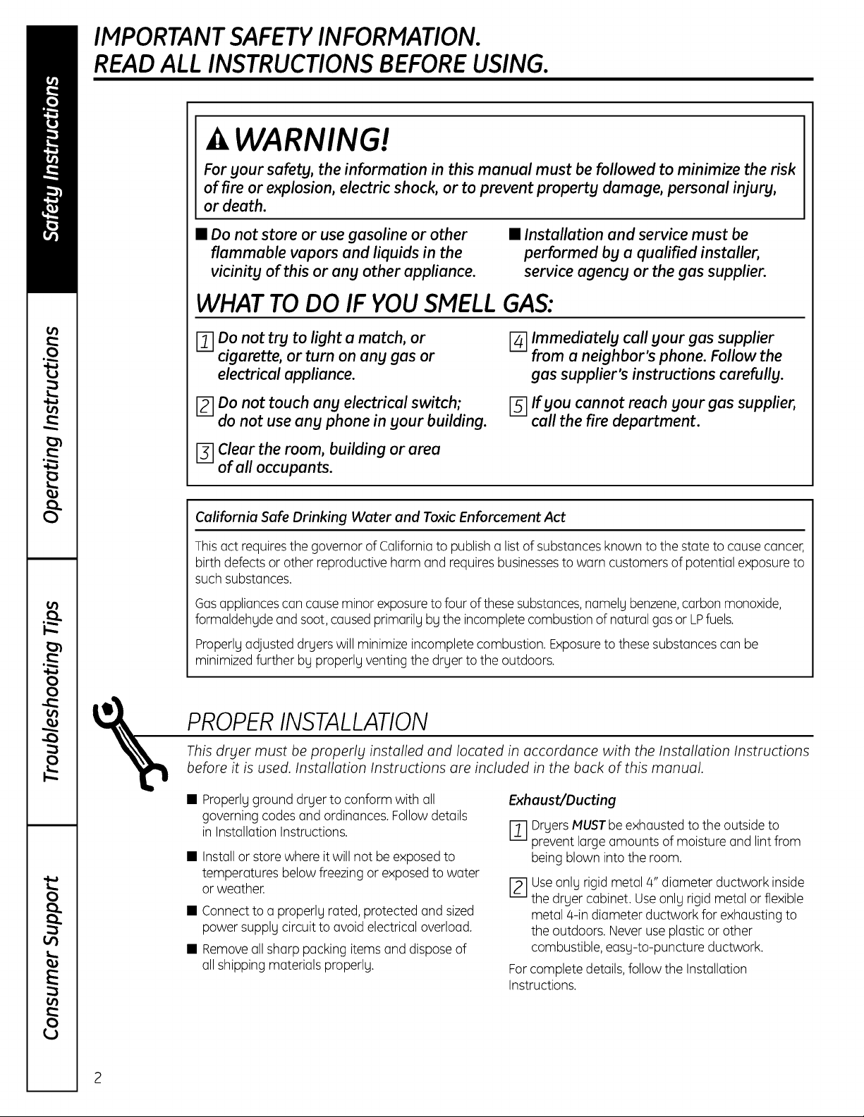
WARNING!
Forgour safety, the information in this manual must be followed to minimize the risk
of fire or explosion, electric shock, or to prevent property damage, persona/injury,
or death.
• Do not store or usegasoline or other
flammable vapors and liquids in the
vicinity of this or ang other appliance.
• Installation and service must be
performed by a qualified installer,
service agency or the gas supplier.
WHAT TODO IF VOUSMELLGAS:
mO.onot try to light a match, or
cigarette, or turn on any gas or
electrical appliance.
r2] Do not touch any electrical switch;
do not use any phone in your building.
[_] Clear the room, building or area
of all occupants.
California Safe Drinking Water and Toxic Enforcement Act
Thisact requiresthegovernor of Californiato publish a list of substances known to the state to cause cancer,
birth defects or other reproductive harm and requiresbusinessesto warn customers of potential exposureto
such substances.
Gosopplioncescon couse minor exposuretofour ofthese substonces,nomely benzene,corbon monoxide,
formoldehyde ond soot, coused primorily by the incompletecombustion of noturol gos or LPfuels.
Properly adjusted dryers will minimize incomplete combustion. Exposureto these substances can be
minimized further by properly venting the dryer to the outdoors.
r_ Immediately call your gas supplier
from a neighbor's phone. Follow the
gas supplier's instructions carefully.
[_] If you cannot reach your gas supplier,
call the fire department.
PROPERINSTALLATION
This dryer must be properly instolled ond Iocoted in occordonce with the Instollotion Instructions
before it is used. Instollotion Instructions ore included in the buck of this monuol.
• Properly ground dryer to conform with all ExhauslYDucting
governing codes and ordinances. Follow details
in Installation Instructions.
Installor store where it will not be exposed to
temperatures below freezing or exposed to water
or weather.
• Connectto a properly rated, protected and sized
power supply circuit to avoid electrical overload.
• Removeallsharp packing items and disposeof
olishipping moteriols properly.
2
I--_-1DryersMUSTbeexhausted to the outside to
prevent large amounts of moisture and lint from
being blown into the room.
rz1 use only rigid metol 4" diometer ductwork inside
the dryer cobinet. Useonly rigid metol or flexible
metol 4-in diometer ductwork for exhousting to
the outdoors. Neveruse plosticor other
combustible, eosy-to-puncture ductwork.
Forcomplete detoils,follow the Instollotion
Instructions.
A WARNING!
YOUR LAUNDRY AREA
GEAppliances.com
Keepthe area underneath and around your
appliances free of combustible materials,
(lint, paper,rags,etc.),gasoline,chemicals
and other flammable vapors and liquids.
Keepthe floor around your appliances clean
and dry to reducethe possibility of slipping.
Closesupervisionis necessary if this appliance is
used by or near children. Do not allow children to
play on,with or insidethis or any other appliance.
WHEN USING YOURDRYER
Neverreach into the dryer while the drum is
moving. Beforeloading, unloading or adding
clothes,wait until the drum has completely
stopped.
Cleanthe lint filter before each load to prevent lint
accumulation insidethe dryer or in the room. DO
NOTOPERATETHEDRYERWITHOUTTHELINT
FILTERIN PLACE.
Donot wash or dry articles that have been
cleaned in,washed in,soaked in or spotted
with combustible or explosivesubstances(such as
wax, oil,paint, gasoline, degreasers,dry-cleaning
solvents,kerosene,etc.).Thesesubstances give
off vapors that may ignite or explode. Donot add
these substances to the wash water. Do not use
or place these substancesaround your washer
or dryer during operation.
Donot place items exposed to cooking oilsin
your dryer. Items contaminated with cooking oils
may contribute to a chemical reaction that could
cause a clothes load to catch fire.
Any article on which you have used a cleaning
solvent or that contains flammable materials
(suchas cleaning cloths, mops,towels used in
beauty salons,restaurants or barber shops,etc.)
must not be placed in or near the dryer until
solvents or flammable materials have been
removed.Thereare many highly flammable items
usedin homes such asacetone, denatured alcohol,
gasoline, kerosene,some household cleaners,some
spot removers,turpentines, waxes, wax removers
and products containing petroleum distillates.
Keepthe area around the exhaust opening
and adjacent surrounding areas freefrom the
accumulation of lint, dust and dirt.
Keepall laundry aids(suchas detergents,
bleaches,etc.)out of the reach of children,
preferably in a locked cabinet. Observeall
warnings on container labelsto avoid injury.
• Neverclimb on or stand on the dryer top.
Thelaundry process can reduce the flame
retardancy of fabrics. Toavoid such a result,
carefully follow the garment manufacturer's
careinstructions.
Donot dry articles containing rubber,plastic
or similar materials such as padded bras,tennis
shoes,galoshes, bath mats, rugs, bibs,baby pants,
plastic bags, pillows,etc.that may melt or burn.
Somerubber materials, when heated, can under
certain circumstances producefire by spontaneous
combustion.
Donot store plastic, paper or clothing that may
burn or melt on top ofthe dryer during operation.
Garments labeled Dry Away from Heat or Do Not
TumbleDry (suchaslifejackets containing Kapok)
must not be put in your dryer.
Donot dry fiberglass articles in your dryer.
Skinirritation could result from the remaining
particles that may be picked up by clothing
during subsequent dryer uses.
Tominimizethe possibility of electric shock, unplug
this appliance from the power supply or disconnect
the dryer at the household distribution panel by
removing the fuse or switching off the circuit
breaker before attempting any maintenance or
cleaning (exceptthe removal and cleaning of the
lint filter).NOTE:PressingSTART/PAUSEor POWER
doesNOTdisconnect the appliance from the power
supply.
Ifyou seewater on the floor around the dryer,
callfor service.
IMPORTANTSAFETYINFORMATION.
READALL INSTRUCTIONSBEFOREUSING.
WARNING!
WHEN USING YOURDRYER(cont.)
Neverattempt to operate this appliance if it is •
damaged, malfunctioning, partially disassembled,
or has missing or broken parts, including a
damaged cord or plug. •
Theinterior of the machine and the exhaust duct
connection insidethe dryer should be cleaned at
least once a year by a qualified technician. See
the Sorting and Loading Hintssection on page 12.
Ifyours isa gas dryer,it isequipped with an
automatic electric ignition and does not have
a pilot light.DO NOTATTEMPTTOLIGHTWITH
A MATCH.Burnsmay result from having your hand
in the vicinity ofthe burner when the automatic
ignition turns on.
Donot open the dryer door during steam cycles.
Thesteam isvery hot and it will continue to
exhaust from the port for severalseconds after
opening. Donot touch the steam port after a
steam cycle.
Donot usea steam cycle with items such
aswool, leather,silk,lingerie, foam products
or electric blankets.
Donot usesteam cycles on new clothes without
first washing.
Youmay wish to soften your laundered fabrics
or reduce the static electricity in them by using
a dryer-applied fabric softener or an anti-static
conditioner.We recommend you useeither
a fabric softener in the wash cycle, according
to the manufacturer's instructions for those
products, or try a dryer-added product for which
the manufacturer giveswritten assurance on
the package that their product can be safely
used in your dryer.Serviceor performance
problems caused by useof these products are
the responsibility of the manufacturers of those
products and are not covered under the warranty
of this appliance.
Neverattempt to usethe Steam Dewrinkleor
Steam Refreshcycles without clothesin the drum.
Additionally, it ishighly recommended to select
the appropriate load sizefor best results.Selecting
large load cycles for small loads may result in
wetting of clothes, and selecting small load cycles
for large loads may result in poor dewrinkling
performance.
WHEN NOT USING YOURDRYER
Graspthe plug firmly when disconnecting this
appliance to avoiddamage to the cord while
pulling. Placethe cord away from traffic areas
so itwill not be stepped on, tripped over or
subjected to damage.
Donot attempt to repair or replaceany part of
this appliance or attempt any servicing unless
specificallyrecommended in this Owner's Manual
or in publisheduser-repairinstructionsthat you
understand and havethe skillsto carry out.
• Beforediscarding a dryer, or removing it from
service,removethe dryer door to prevent children
from hiding inside.
• Do not tamper with controls.
READANDFOLLOWTHISSAFETYINFORMATIONCAREFULLY.
SAVETHESEINSTRUCTIONS
/4
About the dryer controlpanel. GEAppliances.com
WARNING! To_d__h__ko_,__ _ho_ko__j_y_on_o__od_h_,_o_
SAFETY INSTRUCTIONS before operating this appliance.
Throughout this monuol, features ond oppeoroncemog vorg from gout model.
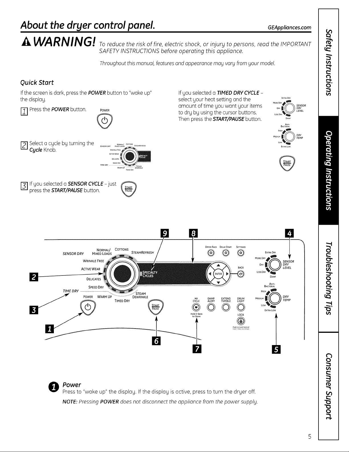
Quick Start
Ifthe screen isdork, pressthe POWERbutton to "woke up"
the displog.
[_ Pressthe POWERbutton. POWER
@
E] Selecto cgcle bg turning the
Cycle Knob.
press the START/PAUSEbutton.
lf gou selected o SENSOR CYCLE-just
SENSOR DRY
TIME DRY ..........................................................................................
_WARM UP DEWRINKL_
MIXED LOADS
WRINKLE FREE
ACTIVEWEAR
DELICATES
SPEEDDRY
NORMAL/ COTTONS
STEAMREFRESH
TIMED DRY CyMcYE
If gou selected o TIMEDDRYCYCLE-
selectgour heot setting ond the
omount oftime gou wont gour items
to drg bg using the cursor buttons.
Then pressthe START/PAUSEbutton.
DRYER RACK DELAY START SETTINGS
BACK
MORELEsIRDDRY(OR SENSORLEvELDRY
®
,t,Z4o_t__
DAMP EXTEND DRUM
ALERT TUMBLE UGHT
©©©
LOCK
M..... _ _ TD6RYI_p
®
od _s_c o Jock
EXTRA DRY
ANTI-
BACTERIAL
N_G_ _D
o_
EXTRA LOW
DAMP
E×T_AORV
MORED_Y_
DAM_
A_rl-
BACTER_At
....s_
M_ou_I _ DRY
E×TRALOW
TEMPow'_
O Power
Pressto "woke up" the displog. If the displog is octive, press to turn the drger off.
NOTE:Pressing POWER does not disconnect the applionce from thepower supplg.
About the dryer controlpanel.
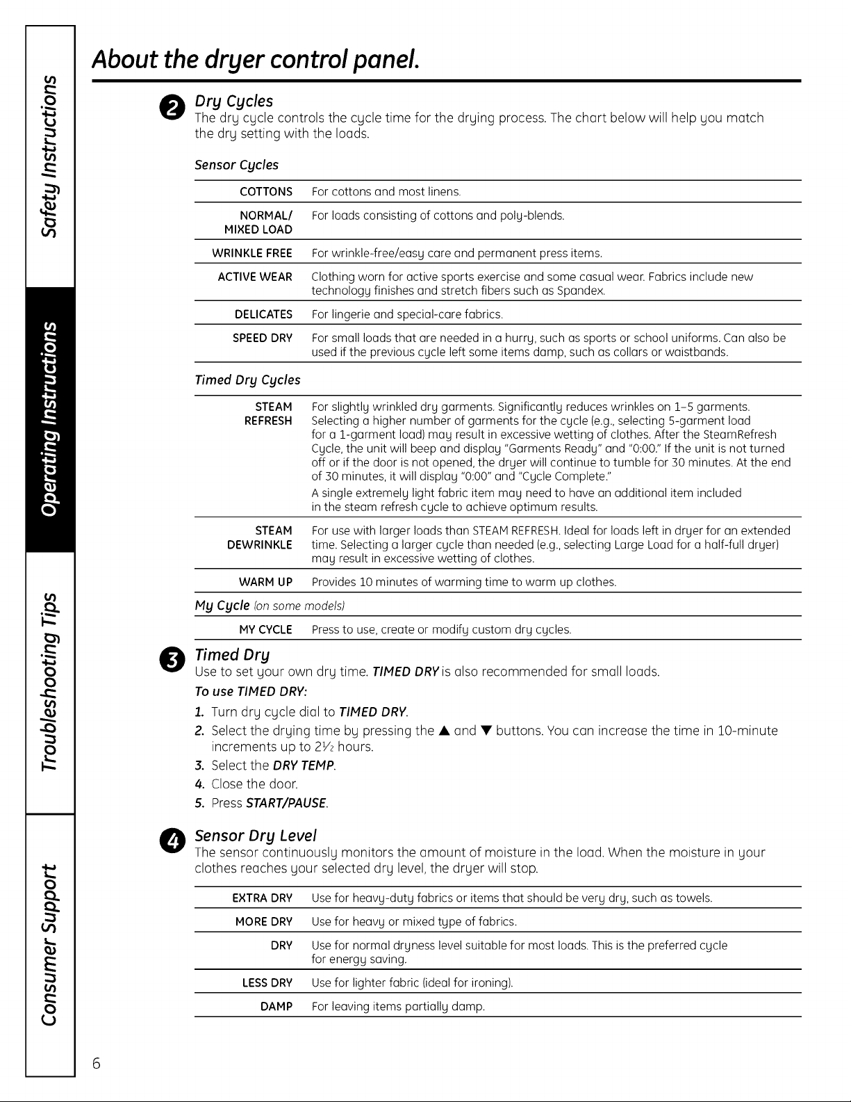
Dry Cycles
The dry cycle controls the cycle time for the drying process.The chart below will help you match
the dry setting with the loads.
Sensor Cycles
COTTONS For cottons and most linens.
NORMAL/ For loads consisting of cottons and poly-blends.
MIXED LOAD
WRINKLE FREE For wrinkle-free/easy care and permanent press items.
ACTIVEWEAR Clothing worn for active sports exercise and some casual wear. Fabrics include new
technology finishes and stretch fibers such as Spandex.
DELICATES For lingerie and special-care fabrics.
SPEEDDRY For small loads that are needed in a hurry, such as sports or school uniforms. Can also be
used if the previous cycle left some items damp, such as collars or waistbands.
Timed Dry Cycles
STEAM
REFRESH
STEAM For use with larger loads than STEAMREFRESH.Ideal for loads left in dryer for an extended
DEWRINKLE time. Selecting a larger cycle than needed (e.g.,selecting Large Load for a half-full dryer)
WARM UP Provides 10 minutes of warming time to warm up clothes.
My Cycle (on some models)
MY CYCLE Pressto use, create or modify custom dry cycles.
Timed Dry
0
Use to set your own dry time. TINED DRYis also recommended for small loads.
To use TINED DRV:
1. Turn dry cycle dial to TINED DRV.
2. Select the drying time by pressing the • and • buttons. You can increase the time in lO-minute
increments up to 2V2 hours.
3. Select the DRV TEMP.
For slightly wrinkled dry garments. Significantly reduces wrinkles on 1-5 garments.
Selecting a higher number of garments for the cycle (e.g.,selecting S-garment load
for a 1-garment load) may result in excessive wetting of clothes. After the SteamRefresh
Cycle, the unit will beep and display "Garments Ready" and "0:00." If the unit is not turned
off or if the door is not opened, the dryer will continue to tumble for 30 minutes. At the end
of 30 minutes, it will display "0:00" and "Cycle Complete."
Asingle extremely light fabric item may need to have an additional item included
in the steam refresh cycle to achieve optimum results.
may result in excessive wetting of clothes.
4. Close the door.
5. Press START/PAUSE.
O Sensor Dry Level
The sensor continuously monitors the amount of moisture in the load. When the moisture in your
clothes reaches your selected dry level, the dryer will stop.
EXTRADRY Usefor heavy-duty fabrics or items that should be very dry, such as towels.
MORE DRY Usefor heavy or mixed type of fabrics.
DRY Usefor normal dryness level suitable for most loads. This isthe preferred cycle
for energy saving.
LESSDRY Use for lighter fabric (ideal for ironing).
DAMP For leaving items partially damp.
6
Dry Temp
You can change the temperature of your dry cycle.
GEAppliances.com
ANTI-BACTERIAL
HIGH
MEDIUM
LOW
EXTRA LOW
START/PAUSE
0
Pressto start o dry cycle. If the dryer is running, press it once and it will pause the dryer.
Pressit again to restart the dry cycle.
MY MUgCycle (onsomemodels)
0
CYCLE
Set up your favorite combination of settings and save them here for one touch recall.
These custom settings can be set while a cycle is in progress.
This option may only be used with COTTONSor MIXED LOAD cycles. This option reduces
certain types of bacteria by 99.9%, including: Staphylococcus oureus, Pseudomonos
oeruginoso and Ktebsiettopneumonioe*. The anti-bacterial process occurs when high
heat is used during a portion of this drying cycle.
NOTE:Do not use this cycle on delicate fabrics.
* The Anti-Bacterial Cycle is Certified by NSFinternational (formerly National Sanitation
Foundation) to NSFProtocol P154 Sonitizotion Performance of Residential Clothes Dryers.
Sanitization Pert_brmance ot
Residential Clothes Dryers
For regular to heavy cottons.
For synthetics, blends and items labeled permanent press.
For delicates, synthetics and items labeled Tumble Dry Low.
For lingerie and special-care fabrics.
To store u MY CYCLEcombinution of settings:
1. Select your drying cycle.
2. Change DRY TEMPand SENSORDRYLEVEL settings to fit your needs.
3. Select any drying OPTIONSyou want.
4. Pressand hold the MYCYCLEbutton for 3 seconds to store your selection. A beep will sound
and the button will light up.
To recull gour stored MY CYCLEcombinution:
Pressthe MY CYCLEbutton before drying a load. The light around the button will light up when
MYCYCLEis selected.
To chunge your stored MY CYCLE combinution:
Follow Steps 1-4 in "To store u MY CYCLE combinution of settings."
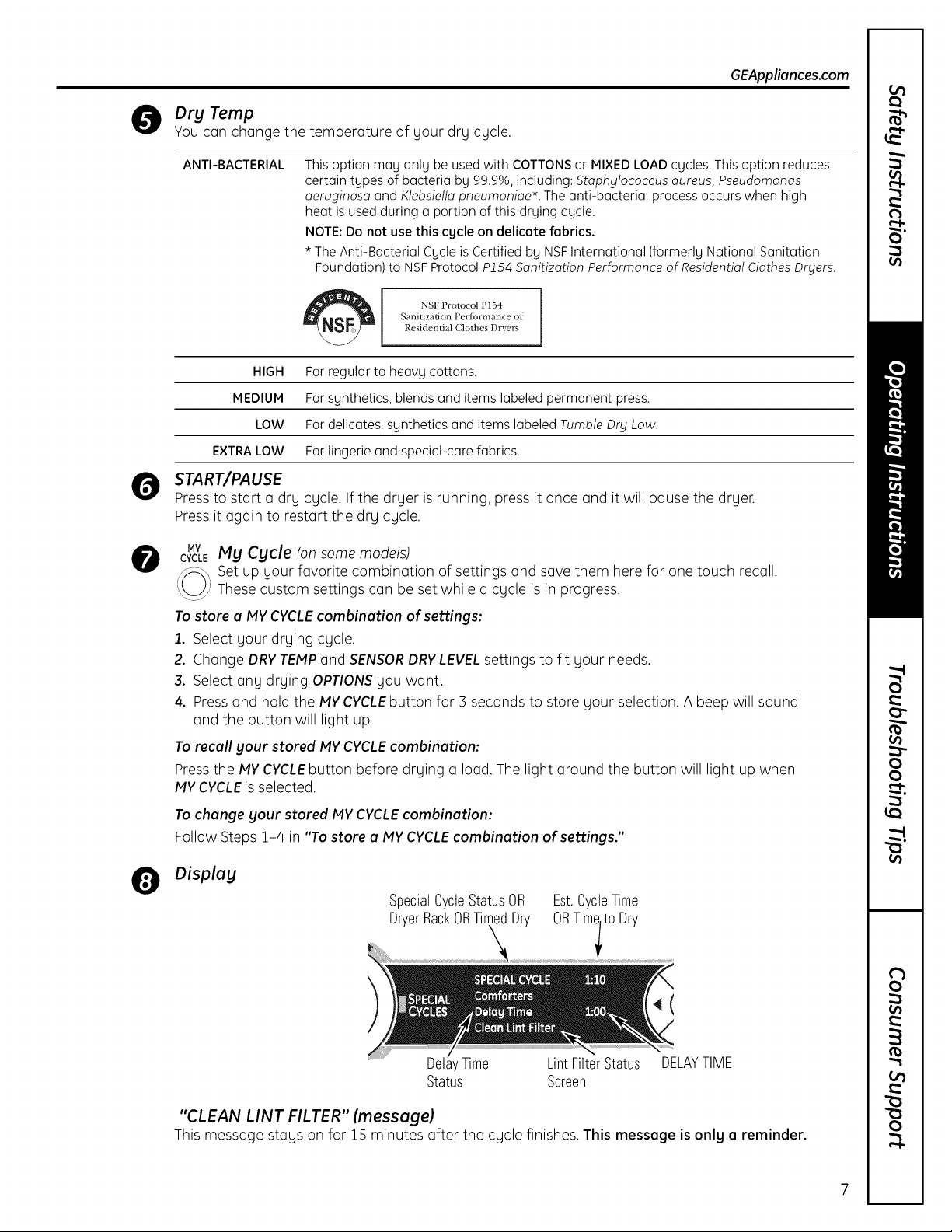
Displag
SpecialCycleStatusOR
DryerRackORTimedDry
Est.CycleTime
ORTimlt0 Dry
4(
LintFilterStatus DELAYTIME
Status Screen
"CLEAN LINT FILTER" (message)
This message stays onfor 15 minutes after the cycle finishes. This message isonlg a reminder.

About the dryer controlpanel.
Specialty Cycles
0
1. Turn the CYCLEknob to SPECIALCYCLES.Alist of cycle options will appear in the display.
2. Using the cursor buttons, select a CATEGORY.
3. Using the cursor buttons, select a CYCLE.
Pressthe BACK button to take you back to the CATEGORIES.
4. PressENTERto select.
5. Press the START/PAUSEbutton.
SPECIALTVCVCLESinclude:
Garments
• Coots
• Hosiery/Bras (use mesh bag)
•Jeans
• Khakis
Bed and Bath
• Blankets (Cotton)
• Comforters
• Sheets
• Towels
Other Specialty
• Air Fluff
• Dryel
• Fleece
• Fragile Cotton
• Performance Fabrics
• Pet Bedding
• Play Clothes
• Sleeping Bags
• Rack Dry
• Throw Rugs
Washer Communicated Cycles
Toturn on communication, pressthe
SETTINGSbutton on the washer control
panel. When "DRYERLINK"appears in the
display, press ENTER.Using the arrow keys,
select ON;then press ENTER.
When the washer cycle is completed, the
washer will communicate with the dryer
when any button on the control panel is
touched or the door isopened.
The washer will display, "TRANSFERRING
CYCLEINFORMATIONTOTHE DRYER"and
the dryer will display, "RECEIVINGCYCLE
INFORMATIONTOTHEDRYER".
8
The dryer will only communicate with the
washer if the dryer is not running a cycle.
If the washer starts a new cycle before the
dryer has a chance to communicate with
it, the information will be lost.
About cycle options.
NOTE: Not all features are available on all dryer models. GEAppliances.com
EXTEND
TUMBLE
ALERT
i i i i
DRUM
LIGHT
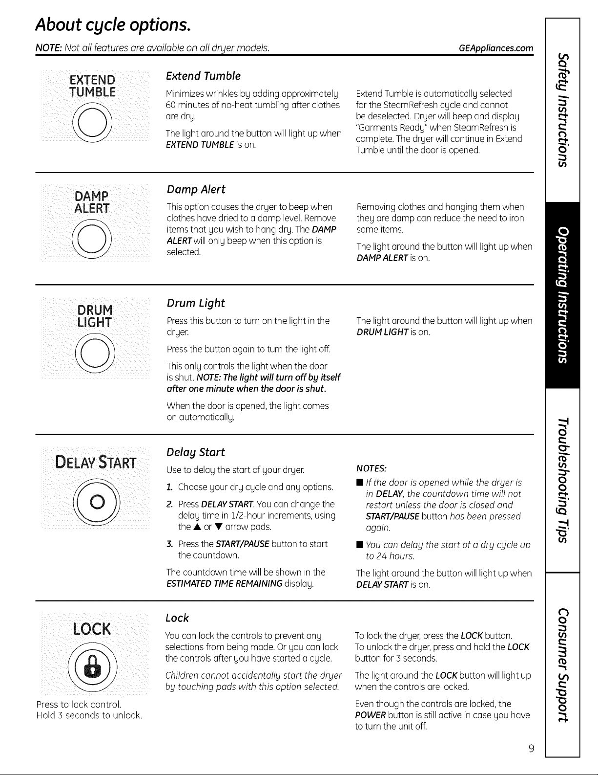
Extend Tumble
Minimizeswrinkles bg adding approximatelg
60 minutes of no-heat tumbling after clothes
are drg.
Thelight around the button will light up when
EXTENDTUMBLEison.
Damp Alert
Thisoption causesthe dryer to beep when
clothes havedried to a damp level.Remove
itemsthat gou wish to hang drg.The DAMP
ALERTwillonlg beepwhen this option is
selected.
Drum Light
Pressthis button to turn on the light in the
drger.
Pressthe button again to turn the light off.
ExtendTumble isautomaticallg selected
for the SteamRefreshcgcle and cannot
be deselected. Drgerwill beep and displag
"Garments Ready"when SteamRefreshis
complete. Thedryer will continue in Extend
Tumble until the door isopened.
Removingclothes and hanging them when
theg are damp can reducethe needto iron
some items.
The light around the button will light up when
DAMPALERTison.
The light around the button will light up when
DRUMLIGHTison.
Thisonlg controls the light when the door
isshut. NOTE:Thelight will turn off by itself
after oneminute when thedoor is shut.
When the door isopened,the light comes
on outomoticollg.
Delay Start
DELAYSTAR
Useto delog the start of gour drger.
1. Choose gour drg cgcle and ong options.
2. PressDELAVSTART.Youcon change the
3. PresstheSTART/PAUSEbuttontostart
Thecountdowntimewillbeshown inthe
ESTIMATEDTIMEREMAININGdisploy.
Lock
LOCK
Youcan lock the controls to prevent ang
selectionsfrom being made. Or gou can lock
the controls after gou have started a cgcle.
delog time in 1/2-hour increments,using
the• or• arrowpads,
thecountdown,
NOTES:
• If the door is opened while the drger is
in DELAY, the countdown time will not
restart unless the door is closed and
START/PAUSEbutton has been pressed
again.
• You can delag the start of a drg cgcle up
to 24 hours,
Thelight around the button will light up when
DELAYSTARTison.
Tolock the drger, pressthe LOCKbutton.
Tounlock the drger,press and hold the LOCK
button for 3 seconds.
_iI ii i
Press to lock control.
Hold 3 seconds to unlock.
Children cannot accidentallg start the drger
bg touching pads with this option selected.
Thelight around the LOCKbutton will light up
when the controls ore locked.
Eventhough the controls ore locked,the
POWERbutton isstill active in case gou hove
to turn the unit off.
9
About cycle options.
NOTE: Not all features are available on all dryer models.
Settings
SETTINGS
About dryer features.
Under the SETTINGSoption, you can
adjust the volume or the brightness of
the display.
VOLUME
• End of Cycle (signal) volume can be set
from HIGH, MED, LOW or OFF.
• Control Sounds volume can be set from
HIGH, MED,LOW or OFF.
Drum Lamp
Before replacing the light bulb, be sure to unplug the dryer power cord or
disconnect the dryer at the household distribution panel by removing the
fuse or switching off the circuit breaker. Reach above dryer opening from
inside the drum. Removethe bulb and replace with the same size bulb.
DISPLAV BRIGHTNESS can be set from
HIGH, MED or LOW.
After you have made your selection,
press ENTER.
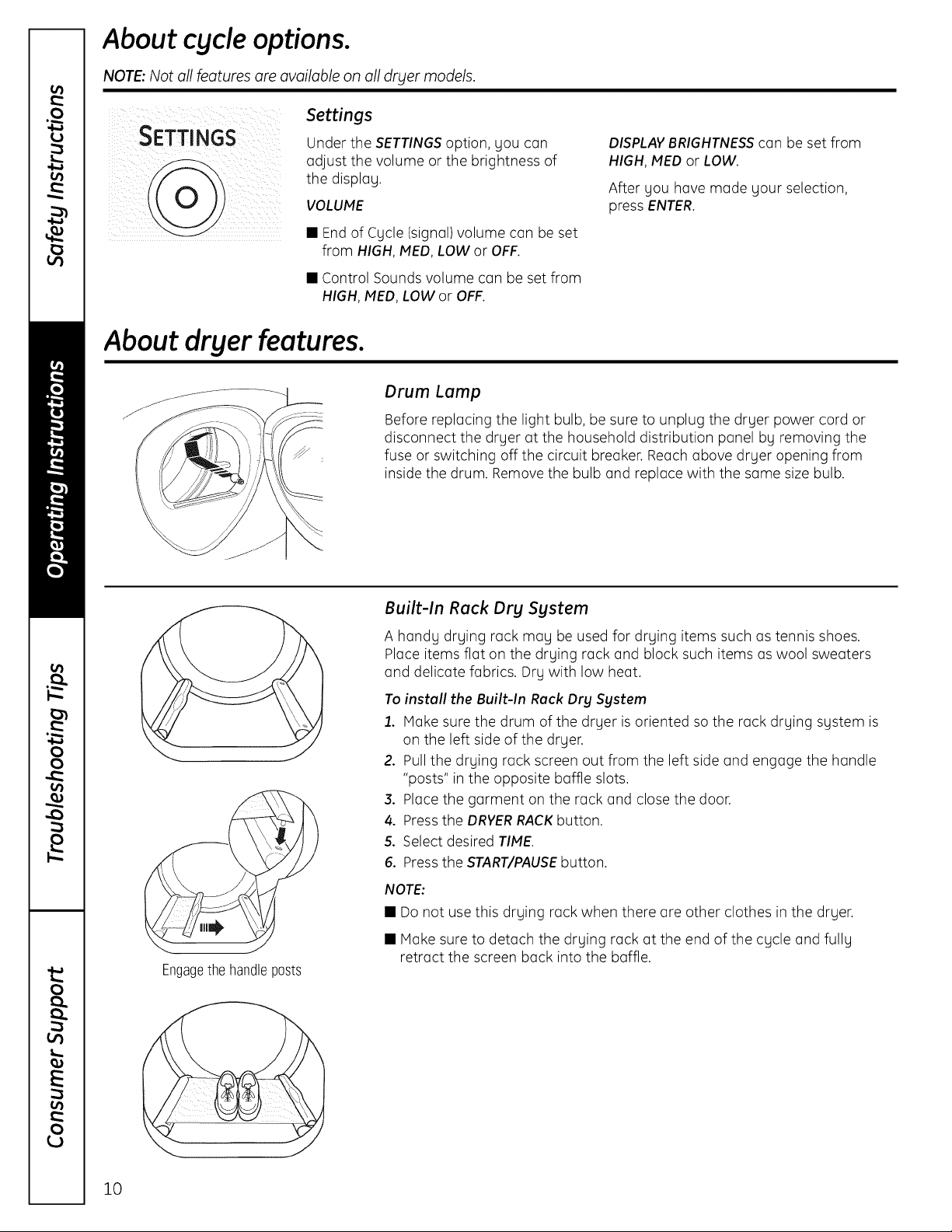
Engagethehandleposts
Built-In Rack Dry System
A handy drying rack may be used for drying items such as tennis shoes.
Place items flat on the drying rack and block such items as wool sweaters
and delicate fabrics. Dry with low heat.
To install the Built-In Rack Dry System
1. Hake sure the drum of the dryer is oriented so the rack drying system is
on the left side of the dryer.
2. Pull the drying rack screen out from the left side and engage the handle
"posts" in the opposite baffle slots.
3. Place the garment on the rack and close the door.
4. Press the DRVERRACKbutton.
5. Select desired TIME.
6. Press the START/PAUSEbutton.
NOTE:
• Do not use this drying rack when there are other clothes in the dryer.
• Make sure to detach the drying rack at the end of the cycle and fully
retract the screen back into the baffle.
10

GEApplionces.com
To Use the Built-In Hook
for Hanging Garments
1. Make sure the drum of the drger is
oriented so the hook is on the top
center of the drger.
2. Using gour finger, pull the hook out
of the baffle.
3. Hang the garment on a hanger,
hang the hanger on the hook and
close the door.
4. Pressthe DRYERRACKbutton.
5. Select the desired time.
6, Pressthe START/PAUSEbutton.
Reverse Tumble TM
All Profile front-load matching drgers are equipped with the Reverse TumbleT"
feature, as part of the Duo Drg Plussgstem T'.Bg reversing the direction
of drum rotation during the drging cgcle, gour drger will tangle the clothes
load less,drg more evenlg and improve drging times. Tgpical loads such
as bed and bath mixed loads, where sheets, towels and pillow cases are
laundered together, benefit from this capabilitg. When the drger reverses
direction, there will be a slight pause and sound change. This is normal.
All drger cgcles utilize this feature, except when the rack drg option is selected,
in which case the drum does not tumble.
11
Using the dryer.
Always follow fabric manufacturer's care label when laundering.
Sorting and Loading Hints
Aso general rule,if clothes ore sorted
properly for the washer,they ore sorted
properly for the dryer.Try also to sort items
according to size.Forexample, do not dry
o sheet with socksor other small items.
Do not odd fabric softener sheetsonce
the load has become worm. They may
cause fabric softener stains. Bounce®
Fabric Conditioner Dryer Sheets hove
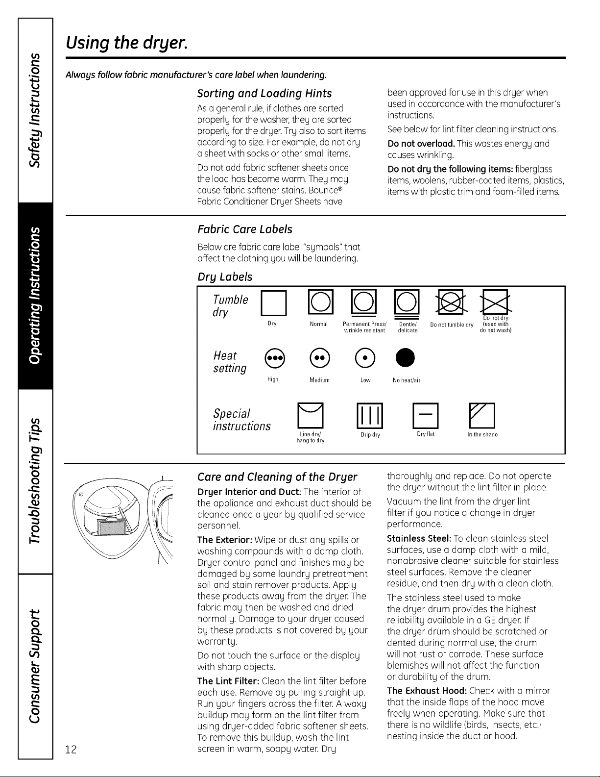
Fabric Care Labels
Belowore fabric care label "symbols" that
affect the clothing you will be laundering.
Dry Labels
dry
Dry Normal Permanent Press/
wrinkle resistant
setting
High Medium Low
been approved for use inthis dryer when
used in accordance with the manufacturer's
instructions.
Seebelow for lintfilter cleaning instructions.
Do not overload. Thiswastes energy and
causeswrinkling.
Do not dry the following items: fiberglass
items,woolens, rubber-coated items, plastics,
items with plastictrim and foam-filled items.
b-qE
Gentle/ De net tumble dry (used with
delicate do not wash)
0
No heat/air
Do not dry
12
instructions
rq Iml
Line dry/ Drip dry
hang to dry
Care and Cleaning of the Dryer
Dryer Interior and Duct: The interior of
the appliance and exhaust duct should be
cleaned once o year by qualified service
personnel.
The Exterior: Wipe or dust any spills or
washing compounds with o damp cloth.
Dryer control panel and finishes may be
damaged by some laundry pretreotment
soil and stain remover products. Apply
these products away from the dryer. The
fabric may then be washed and dried
normally. Damage to your dryer caused
by these products isnot covered by your
warranty.
Do not touch the surface or the display
with sharp objects.
The Lint Filter: Clean the lint filter before
each use. Remove by pulling straight up.
Run your fingers across the filter. A waxy
buildup may form on the lint filter from
using dryer-added fabric softener sheets.
To remove this buildup, wash the lint
screen in warm, soapy water. Dry
Fq
Dry flat
thoroughly and replace. Do not operate
the dryer without the lint filter in place.
Vacuum the lint from the dryer lint
filter if you notice a change in dryer
performance.
Stainless Steel: To clean stainless steel
surfaces, use a damp cloth with a mild,
nonabrasive cleaner suitable for stainless
steel surfaces. Remove the cleaner
residue, and then dry with a clean cloth.
The stainless steel used to make
the dryer drum provides the highest
reliability available in a GEdryer. If
the dryer drum should be scratched or
dented during normal use, the drum
will not rust or corrode. These surface
blemishes will not affect the function
or durability of the drum.
The Exhaust Hood: Check with o mirror
that the inside flaps of the hood move
freely when operating. Hake sure that
there isno wildlife (birds, insects, etc.)
nesting inside the duct or hood.
In the shade
Demand Response. (onsome models) GEAppliunces.com
ModelDPVH891iscompatiblewith the GEDemandResponse
(DR)modulewhich can be purchasedseparately.Contactyour
localutility or visit www.GEApptionces.com/demondresponse
to seeif your area is usingDRtechnology.
Thefollowing demand responsefeaturesare availableas part
of a pilottest program with the local utility company to help
consumersreducepeakelectricity usageinthe home.
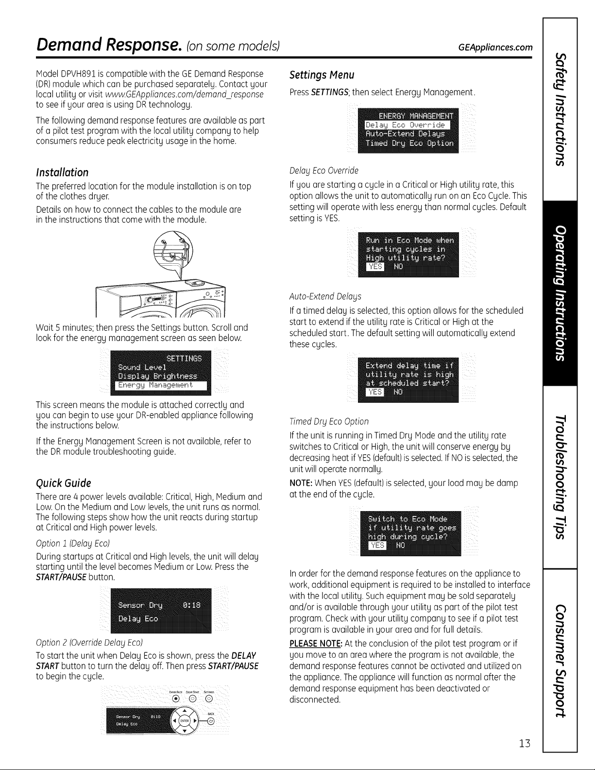
Instollotion
Thepreferredlocationfor the module installationison top
ofthe clothesdryer.
Detailson howto connectthe cablesto the moduleare
in the instructionsthat comewith the module.
Wait 5 minutes;then pressthe Settingsbutton.Scrolland
lookfor the energy management screen as seen below.
Settings Menu
PressSETTINGS;then select Energg Management.
OelogEcoOverride
If gouare starting a cgcle ina Criticalor HighutilitNrate,this
option allowsthe unit to automaticallNrunon an EcoCgcle.This
settingwill operatewith lessenergNthan normal cgcles.Default
setting isYES.
Auto-ExtendOelo_lS
Ifatimed delaNisselected,this option allowsfor the scheduled
start to extend ifthe utilitNrate isCriticalor High at the
scheduledstart. Thedefaultsettingwill automaticallNextend
thesecgcles.
Er_er.gy !"!anager__e.r_t.
Thisscreenmeansthe moduleisattached correctlgand
gou canbeginto use gour DR-enabledappliancefollowing
the instructionsbelow.
If the EnergyManagementScreenisnot available,refer to
the DRmoduletroubleshootingguide.
Quick Guide
Thereare 4 power levelsavailable:Critical,High,Mediumand
Low.Onthe Mediumand Low levels,the unit runsas normal.
Thefollowing stepsshow howthe unit reactsduringstartup
at Criticaland Highpowerlevels.
Option1 (Oelo_lEco)
Duringstartupsat Criticaland Highlevels,the unitwill delag
starting untilthe levelbecomesMediumor Low.Pressthe
START/PAUSEbutton.
Option2 (OverrideOelo_lEco)
Tostart the unitwhen DelaNEcoisshown,pressthe DELAY
STARTbuttonto turn the delaNoff.ThenpressSTART/PAUSE
to beginthe cgcle.
TimedOralEcoOption
Ifthe unit is running inTimed DrNModeandthe utilitNrate
switchesto Critical or High,the unitwill conserveenergNbN
decreasingheatif YES(default)isselected.IfNOisselected,the
unitwill operatenormallN.
NOTE:When YES(default)isselected,gour loadmaNbedamp
at the end ofthe cgcle.
Inorderfor the demandresponsefeatureson the applianceto
work,additionalequipment isrequiredto be installedto interface
with the local utilitN.SuchequipmentmaNbe soldseparatelN
and/or isavailablethroughgour utilitNaspart of the pilottest
program.Checkwith gour utilitNcompanNto seeif a pilottest
programisavailablein gour area and for full details.
PLEASENOTE:Atthe conclusionof the pilottest programor if
goumoveto an areawherethe program isnotavailable,the
demandresponsefeaturescannot be activatedand utilizedon
the appliance.Theappliance willfunction as normalafter the
demandresponseequipment has beendeactivatedor
disconnected.
ii
13
Installation
Dryer
Instructions
In Canada, call 1.800.561.3344 or visit www.GEAppliances.ca
I uestions? Call 800.GE.CARES (800.432.2737) or visit our Web site at: GEAppliances.com
BEFORE YOU BEGIN
Readthese instructions completely and carefully.
• IMPORTANT-Save theseinstructionsforlocal
electrical inspector's use.
• IMPORTANT-Observe all governing codes and
ordinances.
• Installthe clothes dryer according to the manufacturer's
instructions and local codes.
• Note to Installer- Besure to leave these instructions
with the Consumer.
• Note to Consumer - Keepthese instructions for future
reference.
• Clothes dryer installation must be performed by a
qualified installer.
• This dryer must be exhausted to the outdoors.
• Beforethe old dryer is removed from service or
discarded, remove the dryer door.
• Service information and the wiring diagram are located
in the control console.
• Donot allow children on or in the appliance. Close
supervision of children isnecessary when the appliance
is used near children.
• Proper installation isthe responsibility of the installer.
• Product failure due to improper installation is not
covered under the Warranty.
• Install the dryer where the temperature is above 50°F
for satisfactory operation of the dryer control system.
• Removeand discard existing plastic or metal foil duct
and replace with UL-listed duct.
CALIFORNIA SAFE DRINKING WATER AND
TOXIC ENFORCEMENT ACT
This act requires the governor of California to publish a
list of substances known to the state to cause cancer,
birth defects or other reproductive harm and requires
businesses to warn customers of potential exposure to
such substances. Gasappliances can cause minor
exposure to four of these substances, namely benzene,
carbon monoxide, formaldehyde and soot, caused
primarily by the incomplete combustion of natural gas
or LPfuels. Properly adjusted dryers will minimize
incomplete combustion. Exposure to these substances
can be minimized further by properly venting the dryer
to the outdoors.
DPVH891o DPVH890o
FOR YOUR SAFETY:
_aWA RNING- .is,o,Fire
• To reduce the risk of severe injury or death, follow
all installation instructions.
• Clothes dryer installation must be performed by a
qualified installer.
• Install the clothes dryer according to these
instructions and in accordance with local codes.
This dryer must be exhausted to the outdoors.
Use only 4" rigid metal ducting for exhausting the
clothes dryer to the outdoors.
DO NOT install a clothes dryer with flexible plastic
ducting materials. If flexible metal (semi-rigid or
foil-type) duct is installed, it must be UL-listed and
installed in accordance with the instructions found
in "Connecting the Dryer to House Vent" on page 26
of this manual. Flexible ducting materials are known
to collapse, be easily crushed and trap lint. These
conditions will obstruct dryer airflow and increase
the risk of fire.
• Do not install or store this appliance in any location
where it could be exposed to water and/or weather.
• Save these instructions. (Installers: Be sure to leave
these instructions with the customer.)
FOR GAS MODELS ONLY:
NOTE: Installation and service of this dryer must be
performed bg a qualified installer, service agency or
the gas supplier.
In the Commonwealth of Massachusetts:
• This product must be installed bg a licensed
plumber or gas fitter.
• When using ball-type gas shut-off valves, they
shall be T-handle-type.
• A flexible gas connector, when used, must not
exceed 3 feet.
UPVH890
I
14
Installation Instructions
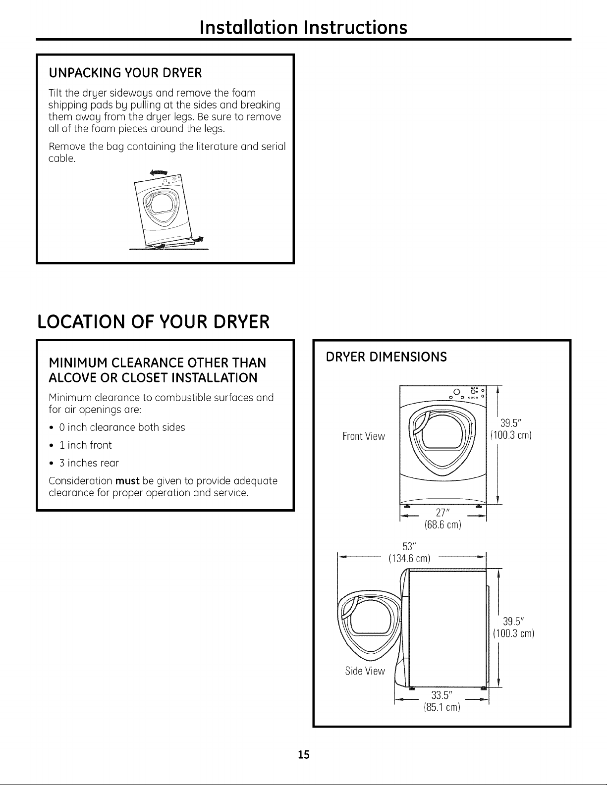
UNPACKING YOUR DRYER
Tilt the dryer sideways and remove the foam
shipping pads by pulling at the sides and breaking
them away from the dryer legs. Be sure to remove
all of the foam pieces around the legs.
Remove the bag containing the literature and serial
cable.
LOCATION OF YOUR DRYER
MINIMUM CLEARANCE OTHER THAN
ALCOVE OR CLOSET INSTALLATION
Minimum clearance to combustible surfaces and
for air openings are:
• 0 inch clearance both sides
• 1 inch front
• 3 inches rear
Consideration must be given to provide adequate
clearance for proper operation and service.
DRYER DIMENSIONS
FrontView
f _
(68.6cm)
53 _'
'_ (134.6cm)
oO_ 8: o
27"
oooo o
T
39.5"
(100.3 cm)
15
39.5"
(100.3cm)
Side View
33.5" __,,,
(85.1 cm)
Instollotion Instructions
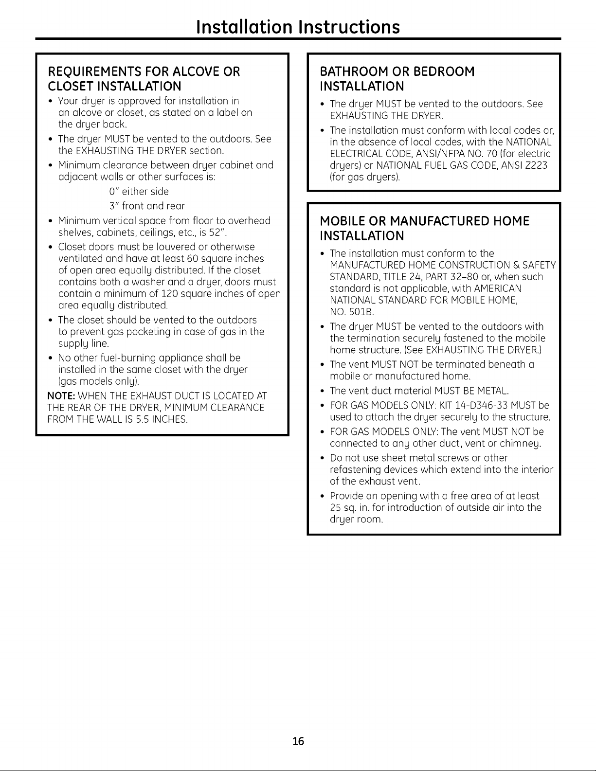
REQUIREMENTS FOR ALCOVE OR
CLOSET INSTALLATION
• Your dryer is approved for installation in
an alcove or closet, as stated on a label on
the dryer back.
• The dryer MUST be vented to the outdoors. See
the EXHAUSTING THE DRYERsection.
• Minimum clearance between dryer cabinet and
adjacent walls or other surfaces is:
0" either side
::3"front and rear
• Minimum vertical space from floor to overhead
shelves, cabinets, ceilings, etc., is 52".
• Closet doors must be Iouvered or otherwise
ventilated and have at least 60 square inches
of open area equally distributed. If the closet
contains both a washer and a dryer, doors must
contain a minimum of 120 square inches of open
area equally distributed.
• The closet should be vented to the outdoors
to prevent gas pocketing in case of gas in the
supply line.
• No other fuel-burning appliance shall be
installed in the same closet with the dryer
(gas models only).
NOTE: WHEN THE EXHAUST DUCT IS LOCATEDAT
THE REAROF THE DRYER, MINIMUM CLEARANCE
FROM THE WALL IS 5.5 INCHES.
BATHROOM OR BEDROOM
INSTALLATION
• The dryer MUST be vented to the outdoors. See
EXHAUSTING THE DRYER.
• The installation must conform with local codes or,
in the absence of local codes, with the NATIONAL
ELECTRICALCODE, ANSI/NFPA NO. 70 (for electric
dryers) or NATIONAL FUEL GAS CODE, ANSI Z223
(for gas dryers).
MOBILE OR MANUFACTURED HOME
INSTALLATION
• The installation must conform to the
MANUFACTURED HOME CONSTRUCTION & SAFETY
STANDARD, TITLE 24, PART:32-80 or, when such
standard isnot applicable, with AMERICAN
NATIONAL STANDARD FOR MOBILE HOME,
NO. 50lB.
• The dryer MUST be vented to the outdoors with
the termination securely fastened to the mobile
home structure. (See EXHAUSTING THE DRYER.)
• The vent MUST NOT be terminoted beneoth o
mobile or manufactured home.
• The vent duct moteriol MUST BE METAL.
• FOR GAS MODELS ONLY: KIT 14-D346-33 MUST be
used to ottoch the dryer securely to the structure.
• FOR GAS MODELS ONLY: The vent MUST NOT be
connected to any other duct, vent or chimney.
• Do not use sheet metol screws or other
refustening devices which extend into the interior
of the exhaust vent.
• Provide an opening with u free urea of at least
25 sq. in. for introduction of outside air into the
dryer room.
16
Installation Instructions
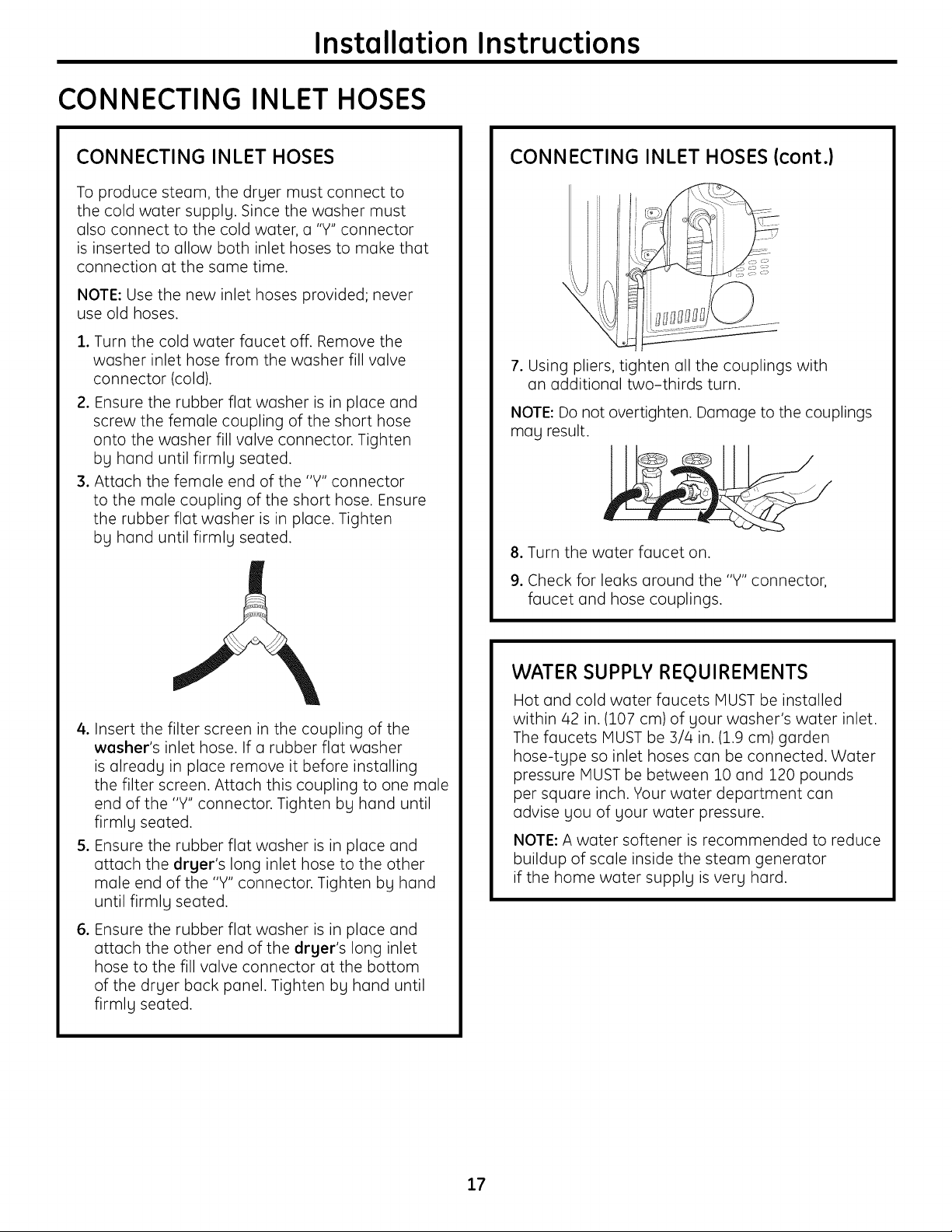
CONNECTING INLET HOSES
CONNECTING INLET HOSES
To produce steam, the dryer must connect to
the cold water supply. Since the washer must
also connect to the cold water, a "Y" connector
is inserted to allow both inlet hoses to make that
connection at the same time.
NOTE: Use the new inlet hoses provided; never
use old hoses.
, Turn the cold water faucet off. Remove the
washer inlet hose from the washer fill valve
connector (cold).
2. Ensure the rubber flat washer is in place and
screw the female coupling of the short hose
onto the washer fill valve connector. Tighten
by hand until firmly seated.
3. Attach the female end of the "Y" connector
to the male coupling of the short hose. Ensure
the rubber flat washer is in place. Tighten
by hand until firmly seated.
CONNECTING INLET HOSES {cont.}
7. Using pliers, tighten all the couplings with
an additional two-thirds turn.
NOTE: Do not overtighten. Damage to the couplings
may result.
8. Turn the water faucet on.
9. Check for leaks around the "Y" connector,
faucet and hose couplings.
4. Insert the filter screen in the coupling of the
washer's inlet hose. If a rubber flat washer
is already in place remove it before installing
the filter screen. Attach this coupling to one male
end of the "Y" connector. Tighten by hand until
firmly seated.
5. Ensure the rubber flat washer is in place and
attach the dryer's long inlet hose to the other
male end of the "Y" connector. Tighten by hand
until firmly seated.
,
Ensure the rubber flat washer is in place and
attach the other end of the dryer's long inlet
hose to the fill valve connector at the bottom
of the dryer back panel. Tighten by hand until
firmly seated.
WATER SUPPLY REQUIREMENTS
Hot and cold water faucets MUST be installed
within/42 in. (107 cm) of your washer's water inlet.
The faucets MUST be ::3//4in. (1.9 cm) garden
hose-type so inlet hoses can be connected. Water
pressure MUST be between 10 and 120 pounds
per square inch. Your water department can
advise you of your water pressure.
NOTE: A water softener is recommended to reduce
buildup of scale inside the steam generator
if the home water supply is very hard.
17
Installation Instructions
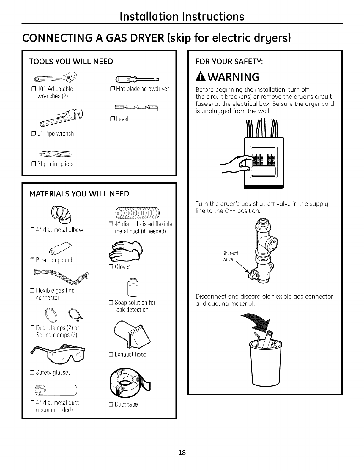
CONNECTING A GAS DRYER(skip for electric dryers)
TOOLS YOU WILL NEED
[] 10" Adjustable
wrenches (2)
[] 8" Pipe wrench
[] Slip-joint pliers
[] Flat-blade screwdriver
[] Level
MATERIALS YOU WILL NEED
%
[] 4" dia. metal elbow
[] 4" dia., UL-listedflexible
metal duct (if needed)
FOR YOUR SAFETY:
-AWARNING
Before beginning the installation, turn off
the circuit breaker(s) or remove the dryer's circuit
fuse(s) at the electrical box. Be sure the dryer cord
is unplugged from the wall.
Turn the dryer's gas shut-off valve in the supply
line to the OFF position.
[] Pipecompound
[] Flexible gas line
connector
%
[] Duct clamps(2) or
Spring clamps (2)
[] Safety glasses
[] 4" dia. metal duct
(recommended)
[] Gloves
[] Soap solution for
leakdetection
[] Exhausthood
[] Duct tape
Shut-off
Valve
Disconnect and discard old flexible gas connector
and ducting material.
18
Installation Instructions
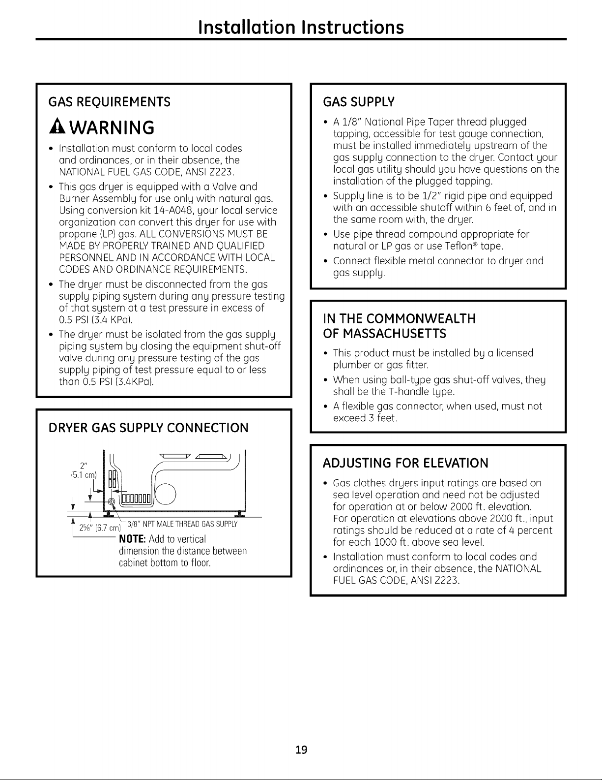
GAS REQUIREMENTS
-AWARNING
Installation must conform to local codes
and ordinances, or in their absence, the
NATIONAL FUELGAS CODE, ANSI Z223.
• This gas dryer is equipped with a Valve and
Burner Assembly for use only with natural gas.
Using conversion kit ]_4-A048, your local service
organization can convert this dryer for use with
propane (LP)gas. ALL CONVERSIONS MUST BE
MADE BY PROPERLYTRAINED AND QUALIFIED
PERSONNEL AND IN ACCORDANCE WITH LOCAL
CODES AND ORDINANCE REQUIREMENTS.
• The dryer must be disconnected from the gas
supply piping system during any pressure testing
of that system at a test pressure in excess of
0.5 PSi (3.4 KPa).
The dryer must be isolated from the gas supply
piping system by closing the equipment shut-off
valve during any pressure testing of the gas
supply piping of test pressure equal to or less
than 0.5 PSi(3.4KPa).
DRYER GAS SUPPLY CONNECTION
GAS SUPPLY
• A 1/8" National Pipe Taper thread plugged
tapping, accessible for test gauge connection,
must be installed immediately upstream of the
gas supply connection to the dryer. Contact your
local gas utility should you have questions on the
installation of the plugged tapping.
• Supply line is to be 1/2" rigid pipe and equipped
with an accessible shutoff within 6 feet of, and in
the same room with, the dryer.
• Use pipe thread compound appropriate for
natural or LPgas or use Teflon ®tape.
• Connect flexible metal connector to dryer and
gas supply.
IN THE COMMONWEALTH
OF MASSACHUSETTS
• This product must be installed by a licensed
plumber or gas fitter.
• When using ball-type gas shut-off valves, they
shall be the T-handle type.
• A flexible gas connector, when used, must not
exceed 3 feet.
2- lu
2%' (6.7.cm) 3/8" NPTMALETHREADGASSUPPLY
/
NOTE: Add to vertical
dimension the distance between
cabinet bottom to floor.
ADJUSTING FOR ELEVATION
Gas clothes dryers input ratings are based on
sea level operation and need not be adjusted
for operation at or below 2000 ft. elevation.
For operation at elevations above 2000 ft., input
ratings should be reduced at a rate of/4 percent
for each 1OOOft. above sea level.
Installation must conform to local codes and
ordinances or, in their absence, the NATIONAL
FUEL GAS CODE, ANSI Z223.
19
Installation Instructions
CONNECTING A GAS DRYER (cont.)
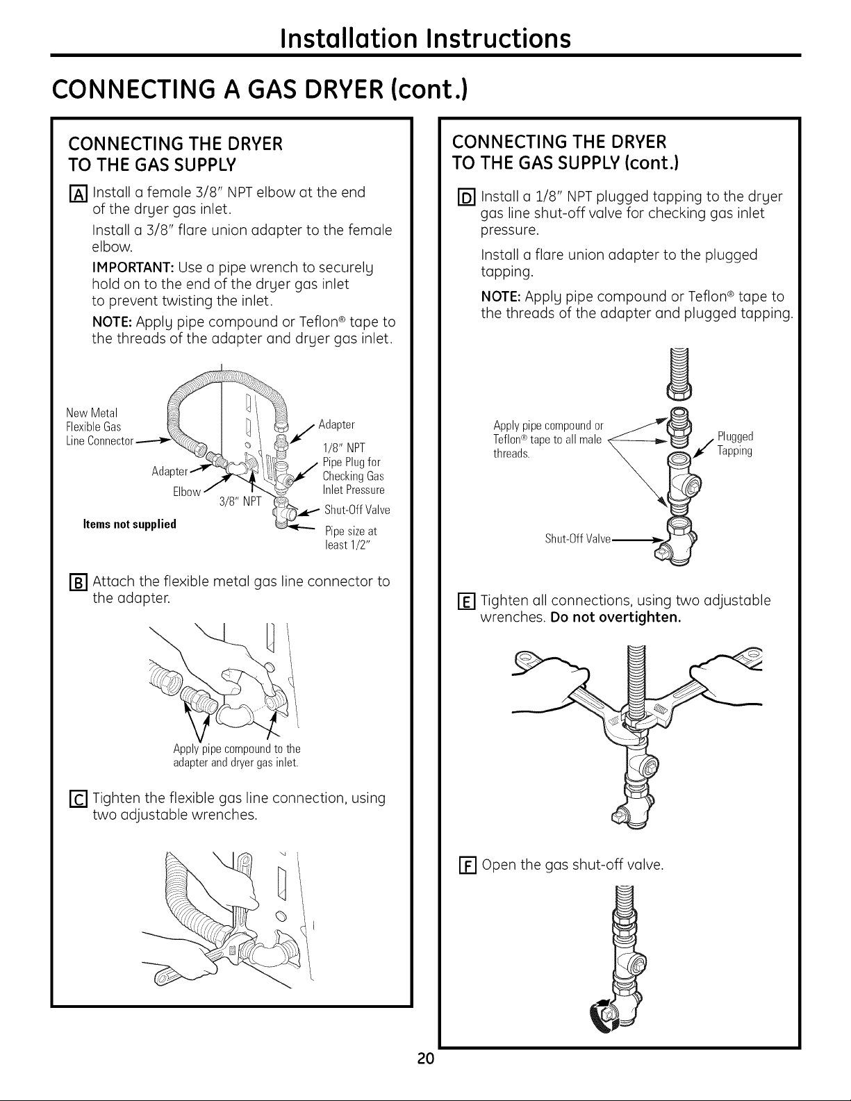
CONNECTING THE DRYER
TO THE GAS SUPPLY
Install a female 3/8" NPT elbow at the end
of the drger gas inlet.
Install a 3/8" flare union adapter to the female
elbow.
IMPORTANT: Use a pipe wrench to securelg
hold on to the end of the drger gas inlet
to prevent twisting the inlet.
NOTE: Applg pipe compound or Teflon ® tape to
the threads of the adapter and drger gas inlet.
NewMetal
FlexibleGas _ I ]I /Adapter
LineConnector___ I _ i "_ 1/8" NPT
Adapter [_1¢" Checking Gas
Elbow/ ix. _ InletPressure
3/8" NPT i%_.. -- Shut-OffVave
Itemsnotsupplied _ Pipesizeat
least1/2"
CONNECTING THE DRYER
TO THE GAS SUPPLY (cont.)
@Install a 2/8" NPT plugged tapping to the dryer
gas line shut-off valve for checking gas inlet
pressure.
Install a flare union adapter to the plugged
tapping.
NOTE: Apply pipe compound or Teflon ® tape to
the threads of the adapter and plugged tapping.
Applypipecompoundor _w'_
Teflon®tapeto all male N_---------b_'_ / Plugged
threads. _ _1¢ Tapping
Shut-OffValve__ !
IB1 Attach the flexible metal gas line connector to
the adapter.
Applypipecompoundtothe
adapteranddryergasinlet.
[] Tighten the flexible gas line connection, using
two adjustable wrenches.
' "4
_j
I-_ Tighten all connections, using two adjustable
wrenches. Do not overtighten.
[] Open the gas shut-off valve.
2O
Installation Instructions
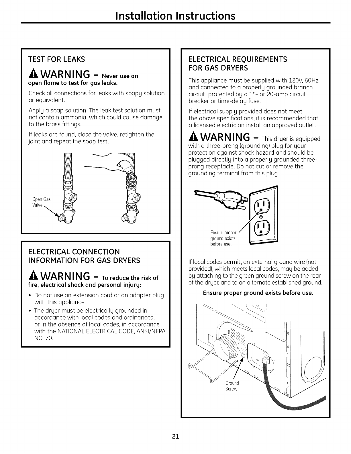
TEST FOR LEAKS
WARNING - Neverusean
open flame to test for gas leaks.
Check all connections for leaks with soapy solution
or equivalent.
Apply a soap solution. The leak test solution must
not contain ammonia, which could cause damage
to the brass fittings.
If leaks are found, close the valve, retighten the
joint and repeat the soap test.
OpenGas
Valve
ELECTRICAL REQUIREMENTS
FOR GAS DRYERS
This appliance must be supplied with 120V, 60Hz,
and connected to a properly grounded branch
circuit, protected by a 15- or 20-amp circuit
breaker or time-delay fuse.
If electrical supply provided does not meet
the above specifications, it is recommended that
a licensed electrician install an approved outlet.
WARNING - Thisdryerisequipped
witha three-prong(grounding)plugforyour
protectionagainstshock hazard and should be
plugged directlyintoa properlygrounded three-
prong receptacle.Do not cutor remove the
groundingterminalfrom thisplug.
ELECTRICAL CONNECTION
INFORMATION FOR GAS DRYERS
-A WARNING - Toreducetheriskof
fire, electrical shock and personal injury:
Do not use an extension cord or an adapter plug
with this appliance.
The dryer must be electrically grounded in
accordance with local codes and ordinances,
or in the absence of local codes, in accordance
with the NATIONAL ELECTRICAL CODE, ANSI/NFPA
NO. 70.
Ensureproper
groundexists
beforeuse.
If local codes permit, an external ground wire (not
provided), which meets local codes, may be added
by attaching to the green ground screw on the rear
of the dryer, and to an alternate established ground.
Ensure proper ground exists before use.
Ground
Screw
21
Installation Instructions
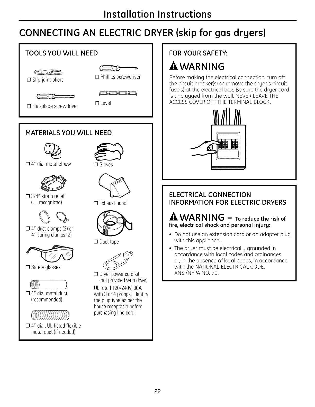
CONNECTING AN ELECTRICDRYER(skip for gas drgers)
TOOLS YOU WILL NEED
[] Slip-joint pliers
[] Flat-blade screwdriver
MATERIALS YOU WILL NEED
[] Phillips screwdriver
[] Level
%
[] 4" dia. metal elbow
[] 3/4" strain relief
(ULrecognized)
[] Gloves
[] Exhausthood
FOR YOUR SAFETY:
-AWARNING
Before making the electrical connection, turn off
the circuit breaker(s) or remove the dryer's circuit
fuse(s) at the electrical box. Be sure the dryer cord
is unplugged from the wall. NEVER LEAVETHE
ACCESSCOVEROFF THE TERMINAL BLOCK.
ELECTRICAL CONNECTION
INFORMATION FOR ELECTRIC DRYERS
%%
[] 4" duct clamps (2) or
4" spring clamps (2)
[] Safety glasses
)
[] 4" dia. metal duct
(recommended)
[] 4" dia., UL-listedflexible
metal duct (if needed)
[] Duct tape
[] Dryerpowercord kit
(notprovidedwith dryer)
ULrated 120/240V,30A
with 3 or 4 prongs.Identify
the plug type as per the
housereceptaclebefore
purchasinglinecord.
-A WARNING - Toreducetheriskof
fire, electrical shock and personal injury:
• Do not use an extension cord or an adapter plug
with this appliance.
• The dryer must be electrically grounded in
accordance with local codes and ordinances
or, in the absence of local codes, in accordance
with the NATIONAL ELECTRICALCODE,
ANSI/NFPA NO. 70.
22
Installation Instructions
ELECTRICAL REQUIREMENTS
FOR ELECTRIC DRYERS
This dryer must be connected to an individual
branch circuit, protected by the required time-
delay fuses or circuit breakers. A three- or four-
wire, single-phase, 120/240V, 60Hz, 30-amp
circuit is required.
If the electric supply does not meet the above
specifications, then call a licensed electrician.
GROUNDING INSTRUCTIONS
This dryer must be connected to a grounded metal,
permanent wiring system, or an equipment-
grounding conductor must be run with the circuit
conductors and connected to the equipment
grounding terminal on the appliance.
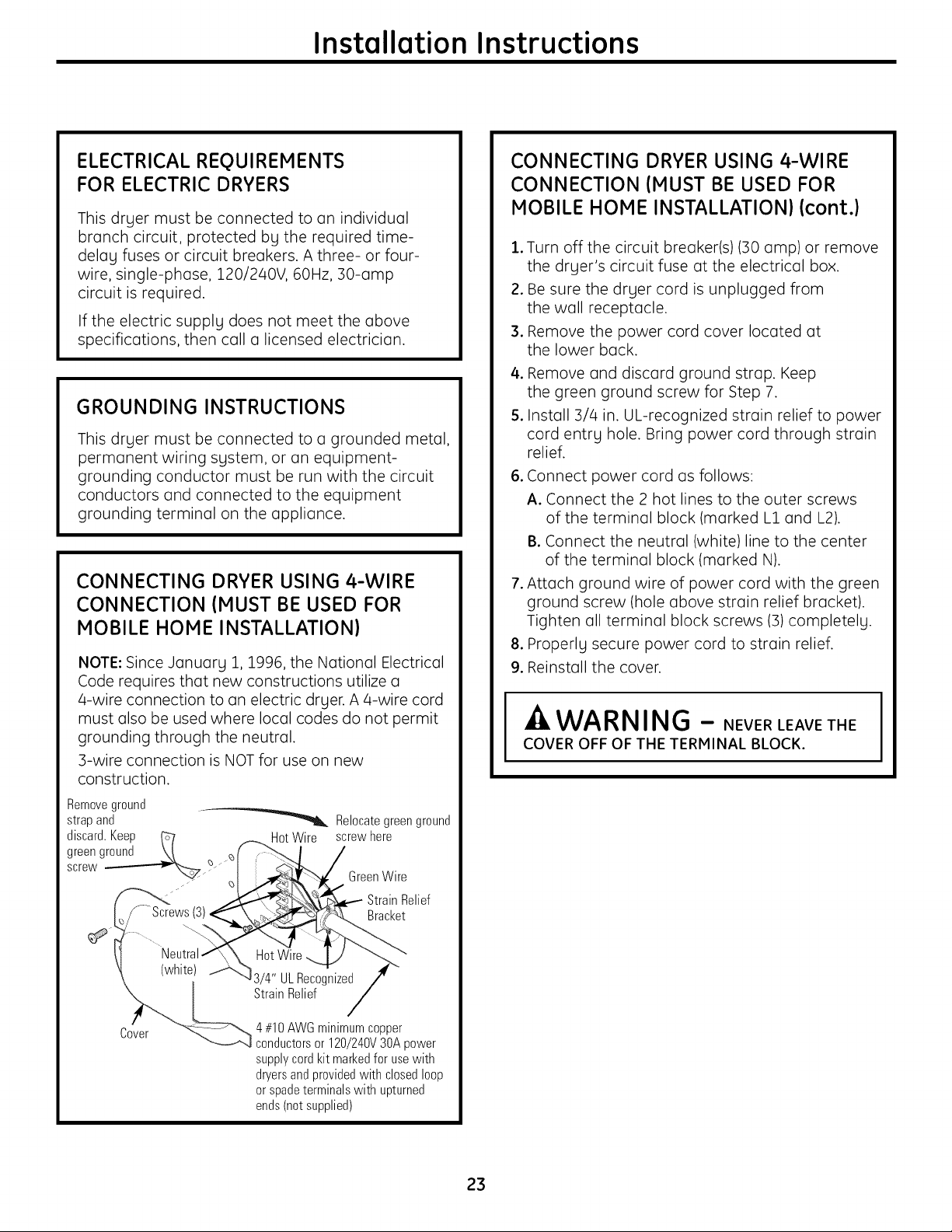
CONNECTING DRYER USING 4-WIRE
CONNECTION (MUST BE USED FOR
MOBILE HOME INSTALLATION}
NOTE: Since January 1, 1996, the National Electrical
Code requires that new constructions utilize a
a-wire connection to an electric dryer. A 4-wire cord
must also be used where local codes do not permit
grounding through the neutral.
3-wire connection is NOT for use on new
construction.
Removeground
strap and "_ Relocate green ground
discard.Keep _7 HotWire screwhere
greenground \/ _f J_.. I /
CONNECTING DRYER USING 4-WIRE
CONNECTION (MUST BE USED FOR
MOBILE HOME INSTALLATION} (cont.}
.
Turn off the circuit breaker(s)(30 amp) or remove
the dryer's circuit fuse at the electrical box.
2.
Be sure the dryer cord is unplugged from
the wall receptacle.
3.
Remove the power cord cover located at
the lower back.
4.
Remove and discard ground strap. Keep
the green ground screw for Step 7.
5.
Install 3/4 in. UL-recognized strain relief to power
cord entry hole. Bring power cord through strain
relief.
.
Connect power cord as follows:
A. Connect the 2 hot lines to the outer screws
of the terminal block (marked L1 and L2).
B.Connect the neutral (white)line to the center
of the terminal block (marked N).
.
Attach ground wire of power cord with the green
ground screw (hole above strain relief bracket).
Tighten all terminal block screws (3) completely.
.
Properly secure power cord to strain relief.
9.
Reinstall the cover.
WARNING - NEVERLEAVETHE
COVER OFF OF THE TERMINAL BLOCK.
screw __ GreenWire
_ __\\_\P-_d-. _ StrainRelief
I_/ Screws(3)_:_X__£._ Bracket
(white_ UL Reco_ized /"
_ [ ..... StrainRelief /
" "_--_ 4#10AWGminimumcopper
_cver _'_-----.A_ conductorsor 120/240V30Apower
supplycordkit markedfor usewith
dryersandprovidedwithclosedloop
or spadeterminalswith upturned
ends(net supplied)
23
Installation Instructions
CONNECTING AN ELECTRICDRYER(cont.)
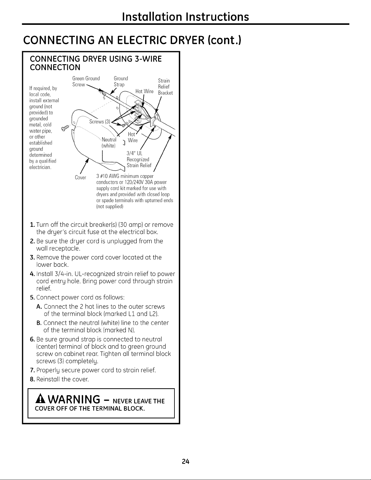
CONNECTING DRYER USING 3-WIRE
CONNECTION
GreenGround Ground Strain
Ifrequired,by
localcode,
installexternal
ground(not
provided)to
grounded
metal,cold
water pipe,
or other
established
ground
determined
bya qualified
electrician.
Screw Strap Relief
HotWire Bracket
Screws
.Neutral Wire
(white) ]
3/4" UL
Recognized
StrainRelief
Cover
3#10AWGminimumcopper
conductorsor 120/240V3OApower
supplycordkit markedfor usewith
dryersandprovidedwith closedloop
or spadeterminalswith upturnedends
(notsupplied)
1.Turn off the circuit breaker(s)(30 amp) or remove
the dryer's circuit fuse at the electrical box.
2. Be sure the dryer cord is unplugged from the
wall receptacle.
3. Remove the power cord cover located at the
lower back.
4. Install 3/4-in. UL-recognized strain relief to power
cord entrg hole. Bring power cord through strain
relief.
5. Connect power cord as follows:
A. Connect the 2 hot lines to the outer screws
of the terminal block (marked L1 and L2).
B.Connect the neutral (white)line to the center
of the terminal block (marked N).
6. Be sure ground strap is connected to neutral
(center) terminal of block and to green ground
screw on cabinet rear. Tighten all terminal block
screws (3) completely.
7. Properly secure power cord to strain relief.
8. Reinstall the cover.
WARNING - NEVERLEAVETHE
COVER OFF OF THE TERMINAL BLOCK.
24
Installation Instructions
EXHAUSTING THE DRYER
-A WARNING - Toreducethe
risk of fire or personal injury:
• This clothes dryer must be exhausted to the outdoors.
• Use only 4" rigid metal ducting for the home
exhaust duct.
• Use only 4" rigid metal or UL-listed flexible metal
(semi-rigid or foil-type) duct to connect the dryer
to the home exhaust duct. It must be installed
in accordance with the instructions found in
"Connecting the Dryer to House Vent" on page 26
of this manual.
• Do not terminate exhaust in a chimney, a wall, a
ceiling, gas vent, crawl space, attic, under an
enclosed floor, or in any other concealed space of
a building.
• Never terminate the exhaust into a common duct
with a kitchen exhaust system. A combination of
grease and lint creates a potential fire hazard.
• Do not use duct longer than specified in the exhaust
length table. Longer ducts can accumulate lint,
creating a potential fire hazard.
• Never install a screen in or over the exhaust duct.
This will cause lint to accumulate, creating a
potential fire hazard.
• Do not assemble ductwork with any fasteners that
extend into the duct. These fasteners can
accumulate lint, creating a potential fire hazard.
• Do not obstruct incoming or exhausted air.
• Provide an access for inspection and cleaning of
the exhaust system, especially at turns and joints.
Exhaust system shall be inspected and cleaned at
least once a year.
• This dryer comes ready for rear exhausting. If space
is limited, use the instructions on pages 29-:31 to
exhaust directly from the sides or bottom of the
cabinet.
EXHAUST SYSTEM CHECKLIST
HOOD OR WALL CAP
• Terminate in a manner to prevent back drafts or
entry of birds or other wildlife.
• Termination should present minimal resistance to
the exhaust airflow and should require little or no
maintenance to prevent clogging.
• Never install a screen in or over the exhaust duct.
• Wall caps must be installed at least 12" above
ground level or any other obstruction with the
opening pointed down.
SEPARATIONOF TURNS
• For best performance, separate all turns by
at least 4 ft. of straight duct, including distance
between last turn and dampened wall cap.
SEALING OF JOINTS
• All joints should be tight to avoid leaks. The male
end of each section of duct must point away
from the dryer.
• Do not assemble the ductwork with fasteners that
extend into the duct. They will serve as a collection
point for lint.
• Duct joints should be made air- and moisture-tight
by wrapping the overlapped joints with duct tape
or aluminum tape.
• Horizontal runs should slope down towards the
outdoors 1/4" per foot.
INSULATION
• Ductwork that runs through an unheated area
or is near air conditioning should be insulated
to reduce condensation and lint buildup.
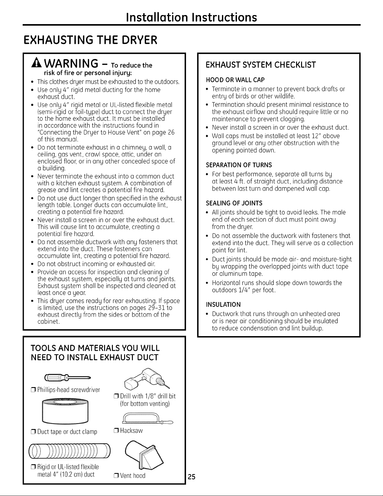
TOOLS AND MATERIALS YOU WILL
NEED TO INSTALL EXHAUST DUCT
[] Phillips-head screwdriver
[] Drill with 1/8" drill bit
(for bottom venting)
[] Ducttape or duct clamp
[] Hacksaw
1)
[] Rigidor UL-listed flexible
metal 4" (10.2cm)duct
[] Vent hood
25
Installation Instructions
EXHAUSTING THE DRYER (cont.)
CONNECTING THE DRYER TO
HOUSE VENT
RIGID METAL TRANSITION DUCT
• For best drying performance, a rigid metal
transition duct is recommended.
• Rigid metal transition ducts reduce the risk of
crushing and kinking.
UL-LISTED FLEXIBLE METAL (SEMI-RIGID)
TRANSITION DUCT
• If rigid metal duct cannot be used, then ULdisted
flexible metal (semi-rigid)ducting can be used
(Kit WX08X10077).
• Never install flexible metal duct in walls, ceilings,
floors or other enclosed spaces.
• Total length of flexible metal duct should not
exceed 8 feet (2.4 m).
• For many applications, installing elbows at both
the dryer and the wall is highly recommended (see
illustrations at right). Elbows allow the dryer to sit
close to the wall without kinking and/or crushing
the transition duct, maximizing drying performance.
• Avoid resting the duct on sharp objects.
UL-LISTED FLEXIBLE METAL (FOIL-TYPE)
TRANSITION DUCT
In special installations, it may be necessary to
connect the dryer to the house vent using a flexible
metal (foil-type)duct. A UL-listed flexible metal
(foil-type) duct may be used ONLY in installations
where rigid metal or flexible metal (semi-rigid)
ducting cannot be used AND where a 4" diameter
can be maintained throughout the entire length
of the transition duct.
In Canada and the United States, only the flexible
metal (foil-type) ducts that comply with the "Outline
for Clothes Dryer Transition Duct Subject 2158A"
shall be used.
Never install flexible metal duct in walls, ceilings,
floors or other enclosed spaces.
Total length of flexible metal duct should not
exceed 8 feet (2.4 m).
Avoid resting the duct on sharp objects.
For best drying performance:
1.Slide one end of the duct over the clothes
dryer outlet pipe.
2. Secure the duct with a clamp.
3. With the dryer in its permanent position,
extend the duct to its full length. Allow 2" of
duct to overlap the exhaust pipe. Cut off and
remove excess duct. Keep the duct as straight
as possible for maximum airflow.
4. Secure the duct to the exhaust pipe with the
other clamp.
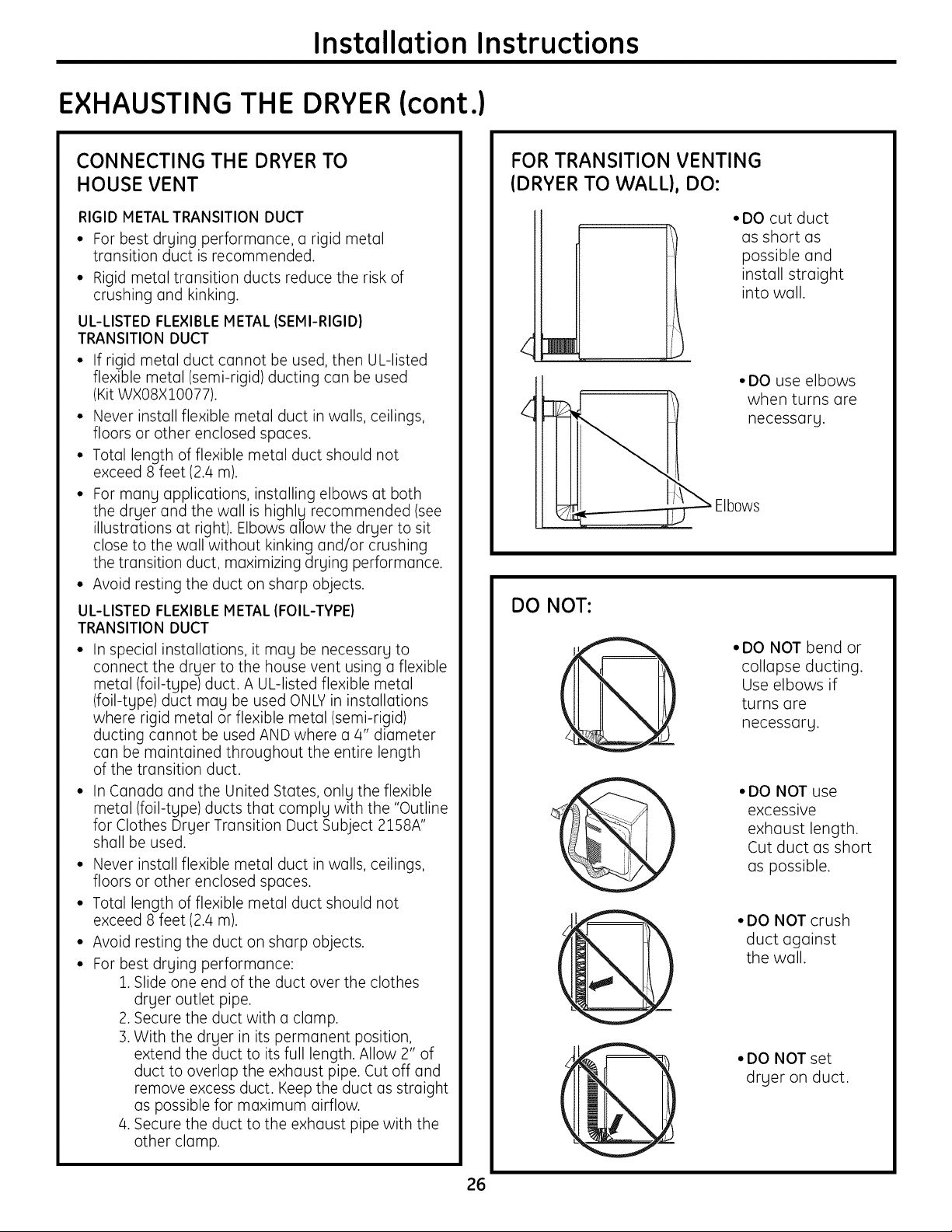
FOR TRANSITION VENTING
(DRYER TO WALL}, DO:
• DO cut duct
DO NOT:
• DO NOT bend or
'@
@
@
@
as short as
possible and
install straight
into wall.
• DO use elbows
when turns are
necessary.
collapse ducting.
Use elbows if
turns are
necessary.
• DO NOT use
excessive
exhaust length.
Cut duct as short
as possible.
•DO NOT crush
duct against
the wall.
• DO NOT set
dryer on duct.
26
Installation Instructions
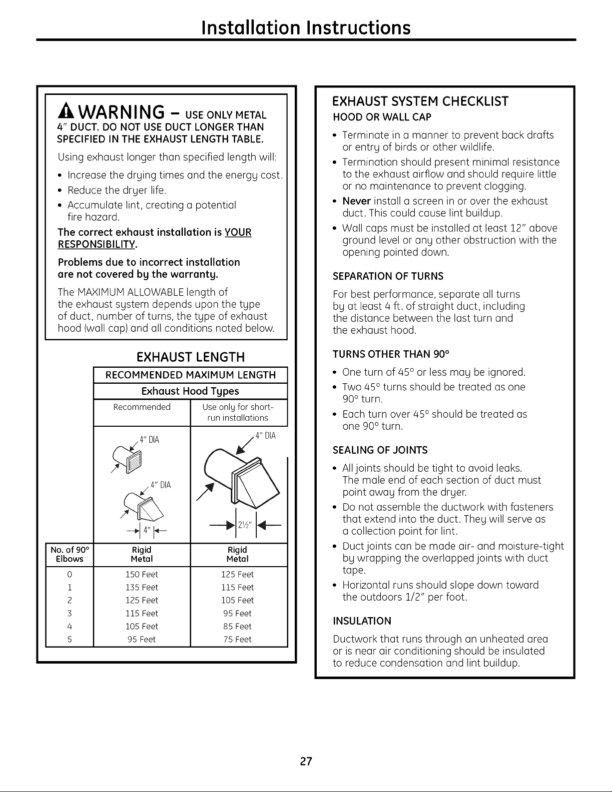
-A WARNING - USEONLYMETAL
4" DUCT. DO NOT USE DUCT LONGER THAN
SPECIFIED IN THE EXHAUST LENGTH TABLE.
Using exhaust longer than specified length will:
• Increase the drging times and the energg cost.
• Reduce the drger life.
• Accumulate lint, creating a potential
fire hazard.
The correct exhaust installation is YOUR
RESPONSIBILITY.
Problems due to incorrect installation
are not covered bg the warrantg.
EXHAUST SYSTEM CHECKLIST
HOOD OR WALL CAP
• Terminate in a manner to prevent back drafts
or entry of birds or other wildlife.
• Termination should present minimal resistance
to the exhaust airflow and should require little
or no maintenance to prevent clogging.
• Never install a screen in or over the exhaust
duct. This could cause lint buildup.
• Wall caps must be installed at least 12" above
ground level or ang other obstruction with the
opening pointed down.
SEPARATION OF TURNS
The MAXIMUM ALLOWABLE length of
the exhaust sgstem depends upon the tgpe
of duct, number of turns, the tgpe of exhaust
hood (wall cap) and all conditions noted below.
EXHAUST LENGTH
RECOMMENDED MAXIMUM LENGTH
Exhaust Hood Types
Recommended Useonlg for short-
run installations
4" DIA
_. 4" DIA
-_ 4" I_---
No. of 90°
Elbows
0
1
2
3
4
5
Rigid
Metal
150 Feet
135 Feet
125 Feet
115 Feet
105 Feet
95 Feet
Rigid
Metal
125 Feet
115 Feet
105 Feet
95 Feet
85 Feet
75 Feet
4" DIA
For best performance, separate all turns
bg at least/4 ft. of straight duct, including
the distance between the last turn and
the exhaust hood.
TURNS OTHER THAN 90 °
• One turn of 45° or less may be ignored.
• Two 45° turns should be treated as one
90 ° turn.
• Each turn over 45 ° should be treated as
one 90° turn.
SEALING OF JOINTS
• All joints should be tight to avoid leaks.
The male end of each section of duct must
point awag from the drger.
• Do not assemble the ductwork with fasteners
that extend into the duct. Theg will serve as
a collection point for lint.
• Duct joints can be made air- and moisture-tight
bg wrapping the overlapped joints with duct
tape.
• Horizontal runs should slope down toward
the outdoors 1/2" per foot.
INSULATION
Ductwork that runs through an unheated area
or is near air conditioning should be insulated
to reduce condensation and lint buildup.
27
Installation Instructions
EXHAUSTING THE DRYER (cont.)
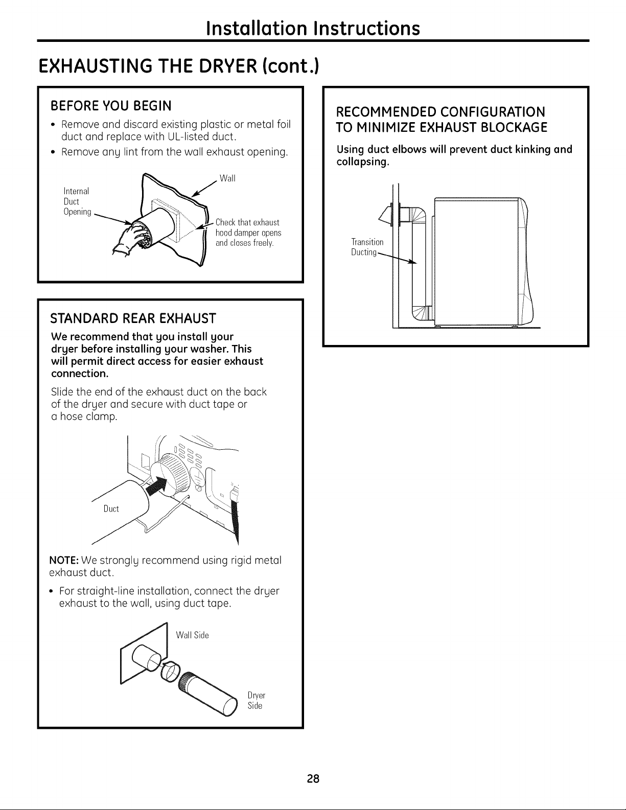
BEFORE YOU BEGIN
• Remove and discard existing plastic or metal foil
duct and replace with UL-listed duct.
• Remove ang lint from the wall exhaust opening.
Wall
Internal
Duct
Opening
"__ Checkthat exhaust
and closes freely.
hooddamperopens
STANDARD REAR EXHAUST
We recommend that gou install gour
drger before installing gour washer. This
will permit direct access for easier exhaust
connection.
Slide the end of the exhaust duct on the back
of the druer and secure with duct tape or
a hose clamp.
RECOMMENDED CONFIGURATION
TO MINIMIZE EXHAUST BLOCKAGE
Using duct elbows will prevent duct kinking and
collapsing.
Transition
Ducting_
Duct
NOTE: We strongly recommend using rigid metal
exhaust duct.
• For straight-line installation, connect the dryer
exhaust to the wall, using duct tape.
Dryer
Side
28
Installation Instructions
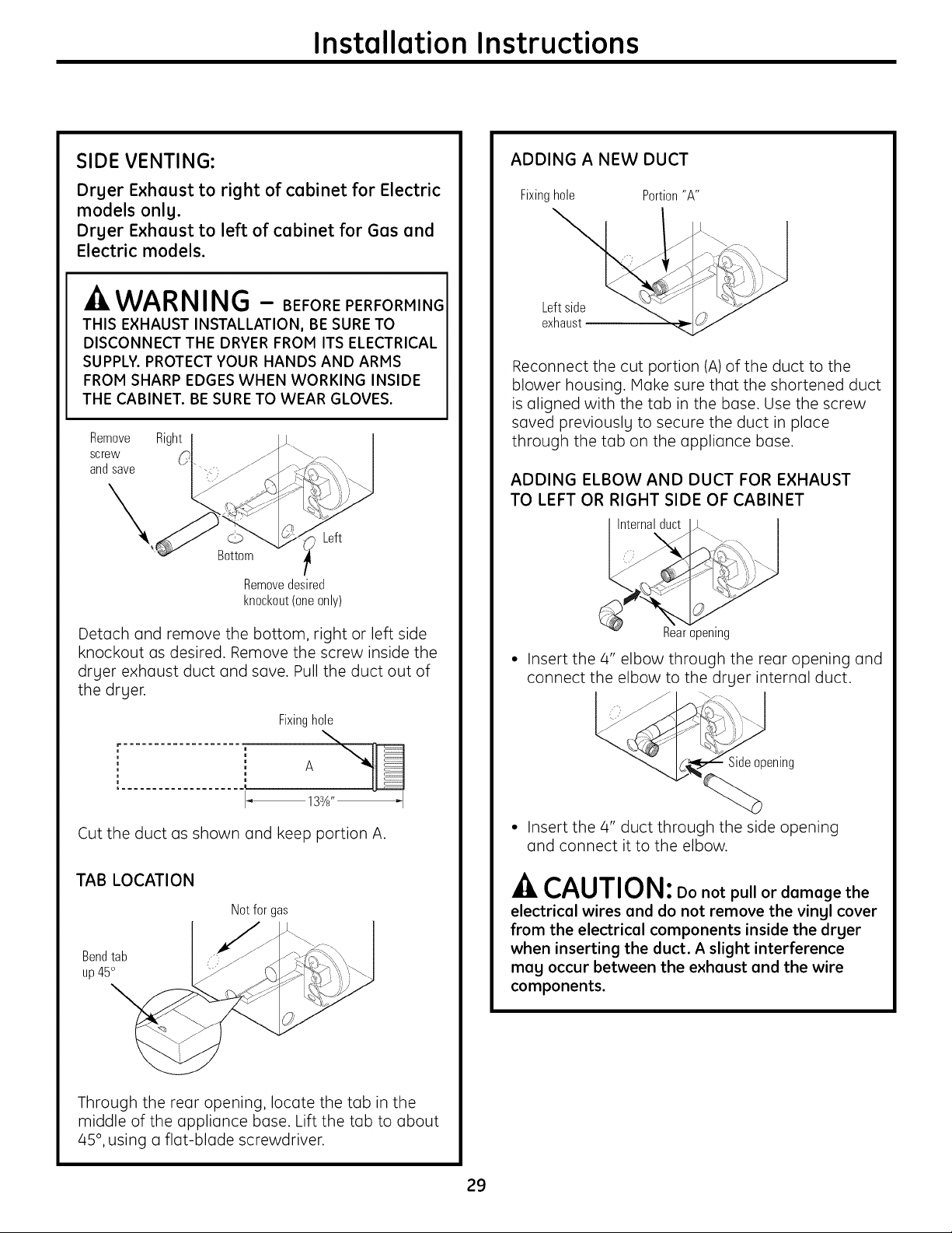
SIDE VENTING:
Dryer Exhaust to right of cabinet for Electric
models only.
Dryer Exhaust to left of cabinet for Gas and
Electric models.
-A WARNING - BEFOREPERFORMING
THIS EXHAUST INSTALLATION, BE SURE TO
DISCONNECT THE DRYER FROM ITS ELECTRICAL
SUPPLY. PROTECT YOUR HANDS AND ARMS
FROM SHARP EDGES WHEN WORKING INSIDE
THE CABINET. BE SURE TO WEAR GLOVES.
Remove
screw
and save
Right
Left
Bottom
Removedesired
knockout(oneonly)
ADDING A NEW DUCT
Fixinghole Portion"A"
Reconnect the cut portion (A)of the duct to the
blower housing. Make sure that the shortened duct
is aligned with the tab in the base. Use the screw
saved previously to secure the duct in place
through the tab on the appliance base.
ADDING ELBOW AND DUCT FOR EXHAUST
TO LEFT OR RIGHT SIDE OF CABINET
Internalduct
Detach and remove the bottom, right or left side
knockout as desired. Remove the screw inside the
dryer exhaust duct and save. Pull the duct out of
the dryer.
Fixinghole
Cut the duct as shown and keep portion A.
TAB LOCATION
Notfor gas
Bendtab
up45°
Rear opening
• Insert the 4" elbow through the rear opening and
connect the elbow to the dryer internal duct.
Sideopening
• Insert the 4" duct through the side opening
and connect it to the elbow.
-A CAUTION: Do not pull or damage the
electrical wires end do not remove the vingl cover
from the electrical components inside the drger
when inserting the duct. A slight interference
meg occur between the exhaust end the wire
components.
Through the rear opening, locate the tab in the
middle of the appliance base. Lift the tab to about
/45°, using a flat-blade screwdriver.
29

Installation Instructions
EXHAUSTING THE DRYER (cont.)
SIDE VENTING (cont.)
ADDING ELBOW AND DUCT FOR EXHAUST
TO LEFT OR RIGHT SIDE OF CABINET (cont.)
• Apply duct tape as
shown on the joint
between the dryer
internal duct and
the elbow, and also
the joint between the "
elbow and the side duct.
Duct
-ACAUTION:
Internal duct joints must be secured with tape;
otherwise, they may separate and cause a safety
hazard.
ADDING COVER PLATE TO REAR OF CABINET
(SIDE EXHAUST)
BOTTOM VENTING:
Drger Exhaust to the bottom of cabinet
for Gas and Electric models.
WARNING - BEFOREPERFORMING
THIS EXHAUST INSTALLATION, BE SURE TO
DISCONNECT THE DRYER FROM ITS ELECTRICAL
SUPPLY. PROTECT YOUR HANDS AND ARMS
FROM SHARP EDGES WHEN WORKING INSIDE
THE CABINET. BE SURE TO WEAR GLOVES.
Remove
screw
and save
Bottom
Removedesired
knockout(oneonly)
Remove the screw inside the dryer exhaust duct
and save. Pull the duct out of the dryer. Detach
and remove the bottom knockout.
Connect standard metal elbows and ducts to
complete the exhaust system. Cover back opening
with a plate (Kit WEllVl4S4) available from your
local service provider. Place dryer in final location.
WAR NING - NEVERLEAVE
THE BACK OPENING WITHOUT THE PLATE.
(Kit WEIM454)
Fixinghole
123_'' _1
Cut the duct as shown and keep portion A.
3O
 Loading...