

GE DPVH890GJ0WW, DPVH890GJ0MV, DPVH890GJ0MG, DPVH890EJ0MV, DPVH890EJ0MG Owner’s Manual
o
CL
ge.com
Safety Instructions ........... 2-4
Operating Instructions
Controls ........................... 5-8
Cycle Options .................... 9, 10
Drger Features .................. 10, 11
Quick Start Guide .................... 5
Settings Option ..................... 10
Using the Drger ..................... 12
Installation Instructions
Before You Begin ................ 13, 14
Connecting the Inlet Hoses ......... 16
Connecting a Gas Drger ........ 17-20
Connecting an
Electric Drger ................... 21-23
Exhausting the Drger ........... 24-30
Final Setup .......................... 31
Installing the Pedestal .......... 41-43
Location of gour Drger .......... 14, 15
Reversing the Door Swing ...... 32-37
Stacking the Washer
and Drger ....................... 38-40
Troubleshooting Tips ...... 44-47
DPVH890
UPVH890
S cheuses
Profile
La section frangaise commence 5 la page 51
Secadoras
Profile
La secci6n en espa_ol empieza en la p6gina 101
Consumer Support
Consumer Support ....... Back Cover
Warrantg (Canada) ................. 50
Warrantg (U.S.)..................... 49
SAVETHESEINSTRUCTIONS
Write the model and serial
numbers here:
Model #
Serial #
Theg are on the label on the front
of the drger behind the door.
175D1807P622 49-90354 09-08 JR
IMPORTANT SAFETY INFORMATION.
READ ALL INSTRUCTIONS BEFORE USING.
WARNING!
For your safety, the information in this manual must be followed to minimize the risk
of fire or explosion, electric shock, or to prevent property damage, personal injury,
or death.
[] Do not store or use gasoline or other
flammable vapors and liquids in the
vicinity of this or any other appliance.
[] Installation and service must be
performed by a qualified installer,
service agency or the gas supplier.
WHAT TO DO IF YOU SMELL GAS:
[] Do not try to light a match, or
agarette, or turn on any gas or
electrical appliance.
[_ Do not touch any electrical switch;
do not use any phone in your building.
[-_ Clear the room, building or area
of all occupants.
California Safe Drinking Water and Toxic Enforcement Act
Thisact requires the governor of Californiato publish a list of substances known to the state to cause cancer,
birth defects or other reproductive harm and requires businessesto warn customers of potential exposureto
such substances.
Gasappliancescan cause minor exposuretofour of thesesubstances,namely benzene,carbon monoxide,
formaldehyde and soot, causedprimarily by the incompletecombustion of natural gasor LPfuels.
Properly adjusted dryers will minimize incomplete combustion. Exposureto these substances can be
minimized further by properly venting the dryer to the outdoors.
[_ Immediately call your gas supplier
from a neighbor's phone. Follow the
gas supplier's instructions carefully.
[_ If you cannot reach your gas supplier,
call the fire department.
%
2
PROPERINSTALLATION
This dryer must be properly installed and located in accordance with the Installation Instructions
before it is used. Installation Instructions are included in the back of this manual.
m Properlyground dryer to conform with all Exhaust/Ducting
governing codes and ordinances. Follow details
in Installation Instructions.
m
Installor store where itwill not be exposed to
temperatures below freezing or exposed to water
or weather.
m Connectto a properly rated, protected and sized
power supply circuit to avoid electrical overload.
m Removeall sharp packing items and disposeof
all shipping materials properly.
r_] DryersMUSTbe exhausted to the outside to
prevent large amounts of moisture and lint from
being blown into the room.
r_--]use only rigid metal4" diameter ductwork inside
the dryer cabinet. Useonly rigid metal or flexible
metal/4-in diameter ductwork for exhausting to
the outdoors. Neveruse plasticor other
combustible, easy-to-puncture ductwork.
Forcomplete details,follow the Installation
Instructions.
WARNING!
YOUR LAUNDRY AREA
m
Keepthe area underneath and around your
appliances free of combustible materials,
(lint, paper,rags,etc.),gasoline, chemicals
and other flammable vapors and liquids.
m
Keepthe floor around your appliances clean
and dry to reduce the possibility of slipping.
m
Closesupervisionis necessary ifthis appliance is
used by or near children. Do not allow children to
play on,with or inside this or any other appliance.
WHEN USING YOUR DRYER
m
Neverreach into the dryer while the drum is
moving. Beforeloading, unloading or adding
clothes,wait until the drum has completely
stopped.
m
Cleanthe lint filter before each load to prevent lint
accumulation inside the dryer or inthe room. DO
NOTOPERATETHEDRYERWITHOUTTHELINT
FILTERIN PLACE.
m
Donot wash or dry articles that hove been
cleaned in,washed in,soaked in or spotted
with combustible or explosive substances(suchas
wax, oil,point, gasoline, degreosers,dry-cleaning
solvents,kerosene,etc.).Thesesubstances give
off vapors that may igniteor explode. Donot add
these substances to the wash water. Donot use
or place these substancesaround your washer
or dryer during operation.
m
Donot place items exposed to cooking oils in
your dryer. Items contaminated with cooking oils
may contribute to a chemical reaction that could
cause a clothes load to catch fire.
m
Any article on which you have used a cleaning
solvent or that contains flammable materials
(suchas cleaning cloths, mops,towels used in
beauty salons, restaurants or barber shops,etc.)
must not be placed in or near the dryer until
solvents or flammable materials have been
removed.There are many highly flammable items
used in homes such asacetone, denatured alcohol,
gasoline, kerosene,somehousehold cleaners,some
spot removers,turpentines, waxes, wax removers
and products containing petroleum distillates.
ge.com
m
Keepthe area around the exhaust opening
and adjacent surrounding areas freefrom the
accumulation of lint, dust and dirt.
m
Keepall laundry aids (suchas detergents,
bleaches,etc.)out of the reach of children,
preferably in a locked cabinet. Observeall
warnings on container labels to avoid injury.
m Neverclimb on or stand on the dryer top.
m
Thelaundry process can reduce the flame
retardancy of fabrics. Toavoid such a result,
carefully follow the garment manufacturer's
care instructions.
m
Donot dry articles containing rubber,plastic
or similar materials such as padded bras,tennis
shoes,galoshes, bath mats, rugs, bibs,baby pants,
plastic bags, pillows,etc.that may melt or burn.
Somerubber materials, when heated, can under
certain circumstances produce fire by spontaneous
combustion.
m
Donot store plastic, paper orclothing that may
burn or melt on top ofthe dryer during operation.
m
Garments labeled Dr_lAwa_lfrom Heat or DoNot
TumbleDry (suchas lifejackets containing Kapok)
must not be put in your dryer.
m
Donot dry fiberglass articles in your dryer.
Skinirritation could result from the remaining
particles that may be picked up by clothing
during subsequent dryer uses.
m
Tominimize the possibility of electric shock, unplug
this appliance from the power supply ordisconnect
the dryer at the householddistribution panel by
removing the fuse or switching off the circuit
breaker before attempting any maintenance or
cleaning (exceptthe removal and cleaning of the
lint filter).NOTE:PressingSTART/PAUSEor POWER
doesNOTdisconnect the appliance from the power
supply.
m
Ifyou seewater on the floor around the dryer,
callfor service.
IMPORTANT SAFETY INFORMATION.
READ ALL INSTRUCTIONS BEFORE USING.
WARNING!
WHEN USING YOUR DRYER(cont.)
m
Neverattempt to operate this appliance if itis
damaged, malfunctioning, partiallg disassembled,
or has missing or broken parts, including a
damaged cord or plug. m
m
Theinterior of the machine and the exhaust duct
connection insidethe dryer should be cleaned at
least once a gearbg a qualified technician. See
the Sorting and Loading Hintssection on page 12.
m
Ifyours is a gas drger,it isequipped with an
automatic electric ignition and does not have
a pilot light. DO NOTATTEMPTTOLIGHTWITH
A MATCH.Burnsmag result from having gour hand
in the vicinity ofthe burner when the automatic
ignition turns on.
m
Donot open the drger door during steam cgcles.
Thesteam is verg hot and itwill continue to
exhaust from the port for severalseconds after
opening. Donot touch the steam port after a
steam cgcle.
m
Donot use a steam cgcle with items such
aswool, leather,silk,lingerie, foam products
or electric blankets.
Donot use steam cgcleson new clothes without
first washing.
Youmag wish to soften gour laundered fabrics
or reduce the static electricitg in them bgusing
a drger-applied fabric softener or an anti-static
conditioner.We recommend gou useeither
a fabric softener inthe wash cgcle,according
to the manufacturer's instructions for those
products, or trg a drger-added product for which
the manufacturer giveswritten assurance on
the package that their product can be safelg
used in gour drger.Serviceor performance
problems caused bg use of these products are
the responsibilitg ofthe manufacturers of those
products and are not covered under the warrantg
of this appliance.
m
Neverattempt to use the Steam Dewrinkleor
Steam Refreshcgcleswithout clothes in the drum.
Additionallg, it ishighlg recommended to select
the appropriate load sizefor best results.Selecting
large load cgclesfor small loads mag result in
wetting of clothes, and selecting small loadcgcles
for large loads mag result in poor dewrinkling
performance.
WHEN NOT USING YOURDRYER
m
Graspthe plug firmlg when disconnecting this
appliance to avoid damage to the cord while
pulling. Placethe cord awag from traffic areas
so itwill not be stepped on, tripped over or
subjected to damage.
m
Donot attempt to repair or replace ang part of
this appliance or attempt ang servicingunless
specificallgrecommended in this Owner's Manual
or in publisheduser-repair instructionsthat gou
understand and havethe skillsto carrg out.
_lE S
FOLLOWTHISSA TV/NFORM, T/ONO R ULLV.
I_'\_ SAVE THESE INSTRUCTIONS
m Beforediscarding a drger,or removing it from
service,remove the drger door to prevent children
from hiding inside.
m Do not tamper with controls.
4
About the dryer control panel, ge.com
SAFETY INSTRUCTIONS before operating this appliance.
Throughout this monuo!,featuresand appearancemog vorg from gout mode!.
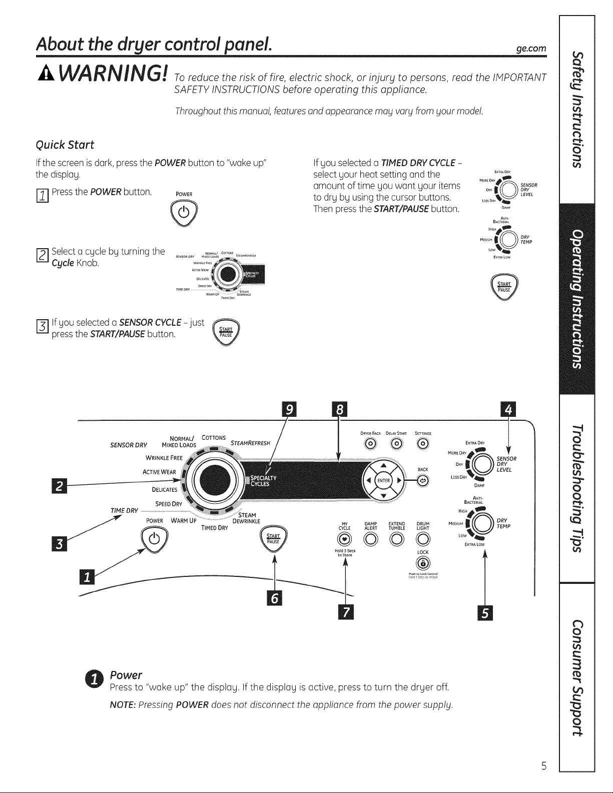
Quick Start
Ifthe screen isdark,pressthe POWERbutton to "woke up"
the display.
r_l Pressthe POWERbutton. POWER
@
r_ Selecto cgcle by turning the
Cycle Knob.
press the START/PAUSE button.
Fiif gou selected o SENSOR CYCLE-just
SENSOR DRY MIXED LOADS STEAMREFRESH
TIME DRY ..........................................................................................
NORMAL/ COTTONS
WRINKLE FREE
ACTIVE WEAR
SPEED DRY
TIMED DRY CyMcYE
If gou selected o TIMEDDRYCYCLE-
selectgour heat setting and the
amount of time you wont your items
to drg bg usingthe cursor buttons.
Then pressthe START/PAUSEbutton.
DRYER RACK DELAY START SETTINGS
I
BACK
MORELEsIRDDRY(gR SENSORLEvELDRY
®
©©©
DAMP EXTEND DRUM
ALERT TUMBLE UGHT
LOCK
M..... _ _ TDERVp4p
®
od _s_c o Jock
EXTRA DRY
ANTI-
BACTERIAL
N_G_ _D
EXTRA LOW
DAMP
E×T_AO_Y
MORED_Y_
DAM_
ANT_-
BACTERIAL
....s_
M_ou__ _ DRY
E×TRALOW
TEMPow'_
Power
Pressto "woke up" the display. If the display is active, press to turn the dryer off.
NOTE:Pressing POWER does not disconnect the appliance from the power supply.
i
About the dryer control panel.
Dry Cycles
The dry cycle controls the cycle time for the drying process. The chart below will help you match
the dry setting with the loads.
Sensor Cycles
COTTONS For cottons and most linens.
NORMAL/ For loads consisting of cottons and poly-blends.
MIXED LOAD
WRINKLE FREE Forwrinkle-freeleasycare and permanent pressitems.
ACTIVE WEAR Clothingworn foractivesportsexerciseand some casual wear. Fabricsincludenew
technology finishesand stretchfiberssuch as Spandex.
DELICATES For lingerieand special-carefabrics.
SPEED DRY For small loads that are needed ina hurry,such as sportsor school uniforms.Can also be
used ifthe previouscycle leftsome items damp, such as collarsor waistbands.
Timed Dry Cycles
STEAM
REFRESH
STEAM For use with larger loads than STEAMREFRESH.Ideal for loads left in dryer for an extended
DEWRINKLE time. Selecting a larger cycle than needed (e.g.,selecting Large Load for a half-full dryer)
WARM UP Provides 10 minutes of warming time to warm up clothes.
My Cycle (on some models)
MY CYCLE Press to use, create or modify custom dry cycles,
For slightly wrinkled dry garments. Significantly reduces wrinkles on 1-5 garments.
Selecting a higher number of garments for the cycle (e.g.,selecting 5-garment load
for a 1-garment load) may result in excessive wetting of clothes. After the SteamRefresh
Cycle, the unit will beep and display "Garments Ready" and "0:00." If the unit is not turned
off or if the door is not opened, the dryer will continue to tumble for 30 minutes. At the end
of 30 minutes, it will display "0:00" and "Cycle Complete."
Asingle extremely light fabric item may need to have an additional item included
in the steam refresh cycle to achieve optimum results.
may result in excessive wetting of clothes.
Timed Dry
Use to set your own dry time. TIMED DRY is also recommended for small loads.
To use TIMED DRY:
1. Turn dry cycle dial to TIMED DRY.
2. Select the drying time by pressing the A and V buttons. You can increase the time in 10-minute
increments up to 2V2 hours.
3. Select the DRY TEMP.
4. Close the door.
5. Press START/PAUSE.
Sensor Dry Level
The sensor continuously monitors the amount of moisture in the load. When the moisture in your
clothes reaches your selected dry level, the dryer will stop.
EXTRADRY Use for heavy-duty fabrics or items that should be very dry, such as towels.
MORE DRY Use for heavy or mixed type of fabrics.
DRY Use for normal dryness level suitable for most loads. This is the preferred cycle
for energy saving.
LESSDRY Use for lighter fabric (ideal for ironing).
DAMP For leaving items partially damp.
6
Dry Temp
You can change the
ge.com
temperature of your dry cycle.
ANTI-BACTERIAL
HIGH
MEDIUM
LOW
EXTRA LOW
START/PAUSE
Pressto start a dry cycle. If the dryer is running, press it once and it will pause the dryer.
Pressit again to restart the dry cycle.
MY My Cycle (on some models)
CYCLE
Set up your favorite combination of settings and save them here for one touch recall.
These custom settings can be set while a cycle is in progress.
This option may only be used with COTTONSor MIXED LOAD cycles. This option reduces
certain types of bacteria by 99.9%, including: Stophylococcus oureus, Pseudomonos
oeruginoso and Kle6siello pneumonioe*. The anti-bacterial process occurs when high
heat is used during a portion of this drying cycle.
NOTE:Do not use this cycle on delicate fabrics.
* The Anti-Bacterial Cycle is Certified by NSFInternational (formerly National Sanitation
Foundation) to NSFProtocol P154 Sonitizotion Performonce of Residentiol Clothes Dryers.
Sanitization Perfbrmance oi
Residential Clothes Dryers
For regular to heavy cottons.
For synthetics, blends and items labeled permanent press.
For delicates, synthetics and items labeled Tum61eDry Low.
For lingerie and special-care fabrics.
i
To store a NY CYCLEcombination of settings:
£ Select your drying cycle.
2. Change DRY TEPlPand SENSORDRYLEVELsettings to fit your needs.
3. Select any drying OPTIONSyou want.
4. Pressand hold the PlYCYCLEbutton for 3 seconds to store your selection. A beep will sound
and the button will light up.
To recall gour stored PIYCYCLEcombination:
Pressthe PlY CYCLEbutton before drying a load. The light around the button will light up when
PlYCYCLEis selected.
To change your stored PlY CYCLE combination:
Follow Steps 1-4 in "To store a PlY CYCLE combination of settings."
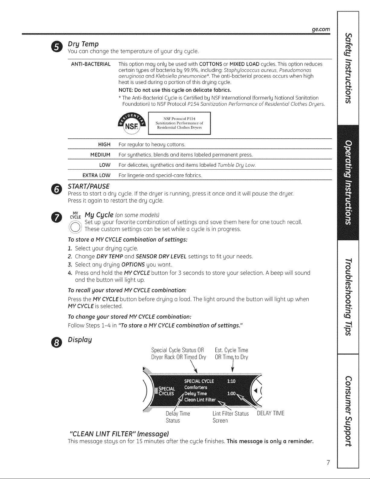
Display
SpecialCycleStatusOR
DryerRackORTimedDry
Est.CycleTime
ORTimlt0 Dry
4(
' Time Lint FilterStatus DELAYTIME
Status Screen
"CLEAN LiNT FILTER" (message)
This message stags on for 15 minutes after the cycle finishes. This message is only a reminder.
About the dryer control panel.
Specialty Cycles
1. Turn the CYCLE knob to SPECIAL CYCLES. Alist of cycle options will appear in the display.
2. Using the cursor buttons, select a CATEGORY.
3. Using the cursor buttons, select a CYCLE.
Press the BACK button to take you back to the CATEGORIES.
4. PressENTERto select.
5. Press the START/PAUSEbutton.
SPECIALTYCYCLESinclude:
Garments
Coots
m Hosierg/Bras (use mesh bag)
m Jeans
m Khakis
Bed end Beth
m Blankets (Cotton)
m Comforters
m Sheets
mTowels
Other Specialty
mAir Fluff
m Drgel
m Fleece
m Fragile Cotton
m Performance Fabrics
m Pet Bedding
m Play Clothes
m Sleeping Bags
m Rack Dry
mThrow Rugs
Washer Communicated Cycles
Toturn on communication, press the
SETTINGSbutton on the washer control
panel. When "DRYERLINK"appears in the
display, press ENTER.Usingthe arrow keys,
select ON;then press ENTER.
When the washer cycle is completed, the
washer will communicate with the dryer
when any button on the control panel is
touched or the door is opened.
The washer will display, "TRANSFERRING
CYCLEINFORMATIONTOTHE DRYER"and
the dryer will display, "RECEIVINGCYCLE
INFORMATIONTOTHEDRYER".
8
The dryer will only communicate with the
washer if the dryer is not running a cycle.
If the washer starts a new cycle before the
dryer has a chance to communicate with
it, the information will be lost.
About cycle options.
NOTE: Not all features are available on all dryer models. ge.com
EXTEND
TU N BLE
ALERT
DRUM
LIGHT
Extend Tumble
Minimizeswrinkles by adding
approximately 60 minutes of no-heat
tumbling after clothes are dry. The beeper
will sound every 2 minutesto remind you
to removethe clothes.TheESTIMATEDTIME
REMAININGdisplay will show 00.
Damp Alert
Thisoption causesthe dryer to beep when
clothes havedried to a damp level. Remove
itemsthat you wish to hang dry.TheDAMP
ALERTwillonly beepwhen this option is
selected.
Drum Light
Pressthis button to turn on the light in the
dryer.
Pressthe button again to turn the light off.
Thelight around the button will light up when
EXTENDTUMBLEison.
ExtendTumble isautomatically selected
for the SteamRefreshcycle and cannot
be deselected. Dryer will beep and display
"Garments Ready" when SteamRefreshis
complete. Thedryer will continue in Extend
Tumble until the door isopened.
Removingclothes and hanging them when
they are damp can reducethe needto iron
some items.
The light around the button will light up when
DAMPALERTison.
The light around the button will light up when
DRUMLIGHTis on.
DELAY START
i(7!i!i ¸¸LL !/ ki ¸
ii ii:ii ii
i ii i iIi
Press to lock control.
Hold 3 seconds to unlock.
Thisonly controls the lightwhen the door
isshut. NOTE:Thelight will turn off bg itself
after one minute when the door is shut.
When the door is opened,the light comes
on automatically.
Delay Start
Useto delay the start of your dryer.
1. Choose your dry cycle and any options.
Z PressDELAYSTART.Youcan change the
delay time in 1/2-hour increments,using
the A or V arrow pads.
3. Pressthe START/PAUSEbutton to start
the countdown.
Thecountdown time will be shown inthe
ESTIMATEDTIMEREMAININGdisplay.
Lock
Youcan lock the controls to prevent any
selectionsfrom being made. Or you can lock
the controls after you have started a cycle.
Children cannot accidentally start the dryer
by touching pads with this option selected.
NOTES:
m If the door is opened while the dryer is
in DELAY,the countdown time wi!! not
restart unless the door is closed and
START/PAUSEbutton has beenpressed
again.
m Youcan delay the start of a dry cycle up
to 24 hours.
Thelight around the button will light up when
DELAYSTARTison.
Tolock the dryer, pressthe LOCKbutton.
Tounlock the dryer,press and holdthe LOCK
button for 5 seconds.
Thelight around the LOCKbutton will light up
when the controls are locked.
Eventhough the controls are locked,
the POWERbutton is still active
in case you have to turn the unit off.
9
About cycle options.
NOTE:Notallfeaturesare availableonalldryer models.
Settings
SETTINGS
kku2,'
Under the SETTINGSoption, you can
adjust the volume or the brightness of
the displag.
VOLUME
m End of Cgcle (signal) volume can be set
from HIGH, PIED,LOW or OFF.
m Control Sounds volume can be set from
HIGH, PIED,LOW or OFF.
About dryer features.
Drum Lamp
Before replacing the light bulb, be sure to unplug the drger power cord or
disconnect the dryer at the household distribution panel bg removing the
fuse or switching off the circuit breaker. Reach above dryer opening from
inside the drum. Remove the bulb and replace with the same size bulb.
DISPLAYBRIGHTNESScan be set from
HIGH, PIED or LOW.
After gou have made gour selection,
press ENTER.
Engagethe handleposts
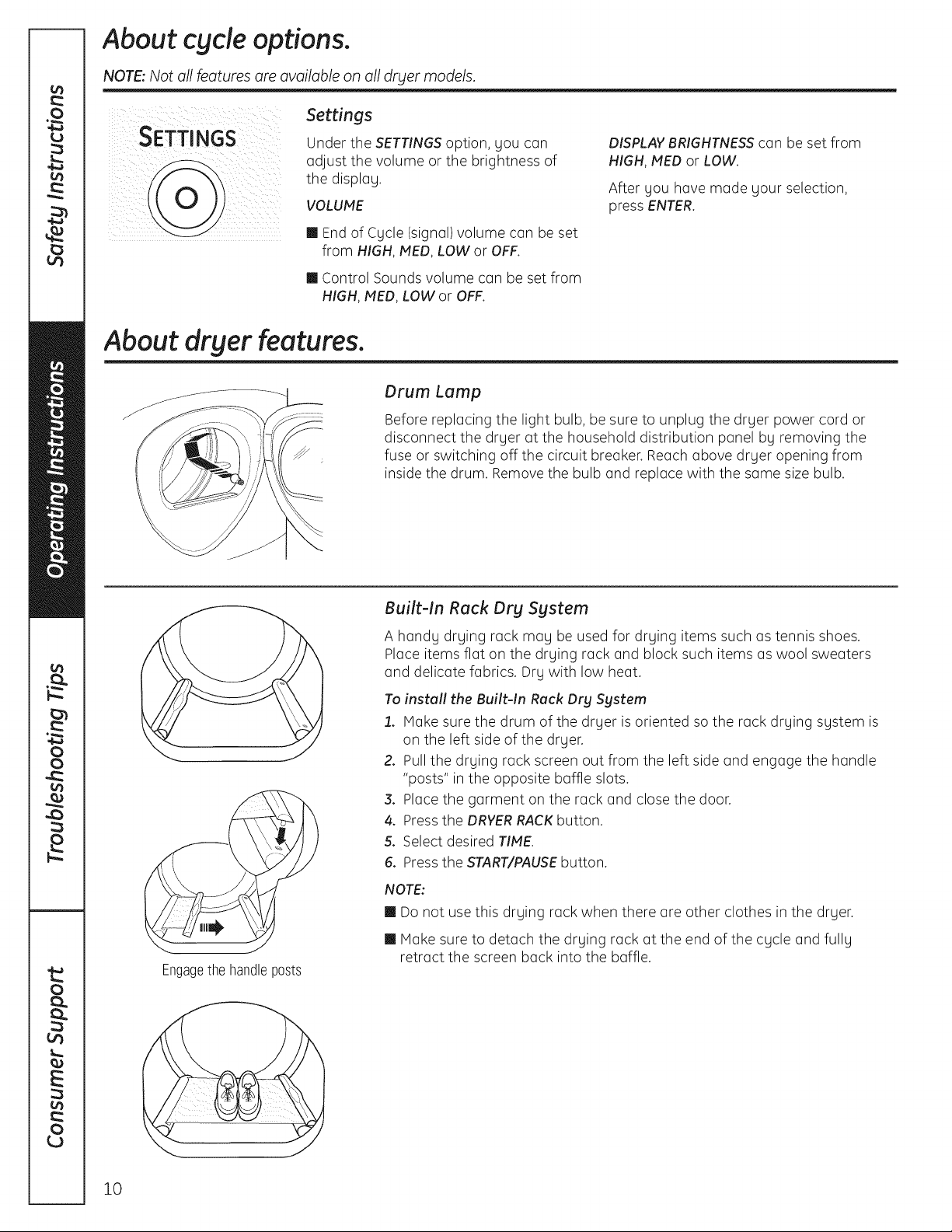
Built-In Rack Dry System
A handg drging rack mag be used for drging items such as tennis shoes.
Place items flat on the drying rack and block such items as wool sweaters
and delicate fabrics. Drg with low heat.
To install the Built-In Rack Dry Sgstem
1. Make sure the drum of the drger is oriented so the rack drging sgstem is
on the left side of the drger.
2. Pull the drging rack screen out from the left side and engage the handle
"posts" in the opposite baffle slots.
3. Place the garment on the rack and close the door.
4. Press the DRYERRACKbutton.
5. Select desired TIPIE.
6. Press the START/PAUSEbutton.
NOTE:
m Do not use this drging rack when there are other clothes in the drger.
m Make sure to detach the drging rack at the end of the cgcle and fullg
retract the screen back into the baffle.
10
ge.com
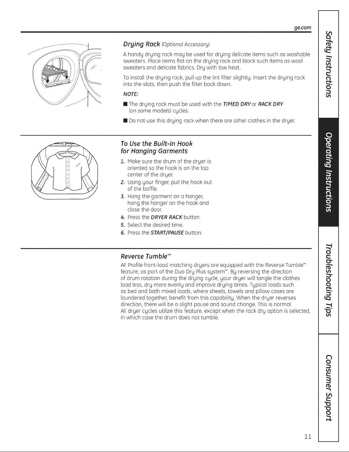
Drying Rock IOptional Accessory)
A handy drying rack may be used for drying delicate items such as washable
sweaters. Place items flat on the drying rack and block such items as wool
sweaters and delicate fabrics. Dry with low heat.
To install the drying rack, pull up the lint filter slightly. Insert the drying rack
into the slots, then push the filter back down.
NOTE:
m The drying rack must be used with the TIMED DRYor RACKDRY
(on some models) cycles.
m Donot use this drying rack when there are other clothes in the dryer.
To Use the Built-In Hook
for Hanging Gorments
1. Make sure the drum of the dryer is
oriented so the hook is on the top
center of the dryer.
2. Using your finger, pull the hook out
of the baffle.
3. Hang the garment on a hanger,
hang the hanger on the hook and
close the door.
4. Pressthe DRYERRACKbutton.
5. Select the desired time.
6. Pressthe START/PAUSEbutton.
Reverse Tumble'"
All Profile front-load matching dryers are equipped with the ReverseTumbleT"
feature, as part of the Duo Dry Plus system _'.By reversing the direction
of drum rotation during the drying cycle, your dryer will tangle the clothes
load less, dry more evenly and improve drying times. Typical loads such
as bed and bath mixed loads, where sheets, towels and pillow cases are
laundered together, benefit from this capability. When the dryer reverses
direction, there will be a slight pause and sound change. This is normal.
All dryer cycles utilize this feature, except when the rack dry option is selected,
in which case the drum does not tumble.
11
Using the dryer.
Always follow fabric manufacturer's care label when laundering.
Sorting and Loading Hints
Asa general rule, ifclothes are sorted
properly for the washer,they are sorted
properly for the dryer.Try also to sort items
according to size.Forexample, do not dry
a sheet with socksor other small items.
Do not add fabric softener sheetsonce
the load has become warm. They may
cause fabric softener stains. Bounce®
Fabric Conditioner Dryer Sheets have
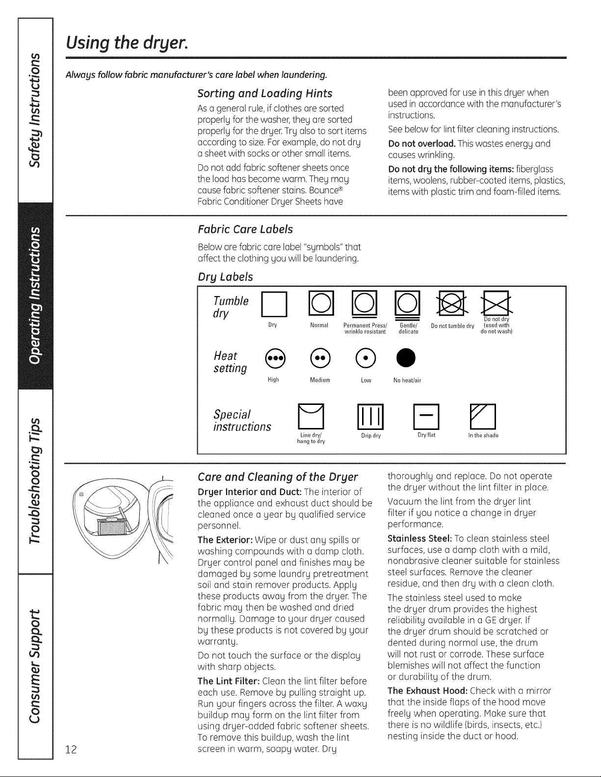
Fabric Care Labels
Beloware fabric care label "symbols" that
affect the clothing you will be laundering.
Dry Labels
dry
N rb-lrOq
Dry Normal Permanent Press/
wrinkle resistant
setting
High Medium Low
been approved for use inthis dryer when
used in accordance with the manufacturer's
instructions.
Seebelow for lintfilter cleaning instructions.
Do not overload. This wastes energy and
causeswrinkling.
Do not drg the following items: fiberglass
items,woolens, rubber-coated items, plastics,
items with plastic trim andfoam-filled items.
Gentle/ Denet tumble dry (used with
delicate do not wash)
Do not dry
0
No heat/air
12
instructions
I=1 Iml
Line dry/ Drip dry
hang to dry
Care and Cleaning of the Dryer
Drger Interior and Duct: The interior of
the appliance and exhaust duct should be
cleaned once a gear by qualified service
personnel.
The Exterior: Wipe or dust any spills or
washing compounds with a damp cloth.
Dryer control panel and finishes may be
damaged by some laundry pretreatment
soil and stain remover products. Apply
these products away from the dryer. The
fabric may then be washed and dried
normally. Damage to your dryer caused
by these products is not covered by your
warranty.
Do not touch the surface or the display
with sharp objects.
The Lint Filter: Clean the lint filter before
each use. Remove by pulling straight up.
Run your fingers across the filter. A waxy
buildup may form on the lint filter from
using dryer-added fabric softener sheets.
To remove this buildup, wash the lint
screen in warm, soapy water. Dry
Fq
Dry flat
thoroughly and replace. Do not operate
the dryer without the lint filter in place.
Vacuum the lint from the dryer lint
filter if you notice a change in dryer
performance.
Stainless Steel: To clean stainless steel
surfaces, use a damp cloth with a mild,
nonabrasive cleaner suitable for stainless
steel surfaces. Remove the cleaner
residue, and then dry with a clean cloth.
The stainless steel used to make
the dryer drum provides the highest
reliability available in a GEdryer. If
the dryer drum should be scratched or
dented during normal use, the drum
will not rust or corrode. These surface
blemishes will not affect the function
or durability of the drum.
The Exhaust Hood: Check with a mirror
that the inside flaps of the hood move
freely when operating. Hake sure that
there isno wildlife (birds, insects, etc.)
nesting inside the duct or hood.
In the shade
I stallti
structi
I
Questions? Call800.GE.CARES (800.432.2737)or visitour Web siteat:ge.com
InCanada, coll1.800.561.3344or visitgeappliances.ca i
DPVH890 and UPVH890
Dryer
BEFORE YOU BEGIN
Read these instructionscompletelyand carefully.
•IMPORTANT- savetheseinstructionsfor
local electrical inspector's use.
• IMPORTANT-Observeallgoverningcodes
and ordinances.
• Install the clothes dryer according to the
manufacturer's instructions and local codes.
• Note to Installer - Be sure to leave these
instructions with the Consumer.
• Note to Consumer - Keep these instructions for
future reference.
• Clothes dryer installation must be performed
by a qualified installer.
• This dryer must be exhausted to the outdoors.
• Before the old dryer is removed from service or
discarded, remove the dryer door.
• Service information and the wiring diagram are
located in the control console.
• Do not allow children on or in the appliance.
Close supervision of children is necessary when
the appliance is used near children.
• Proper installation is the responsibility
of the installer.
FOR YOUR SAFETY:
_WARNI G - RiskofFire
Use only rigid metal or flexible metal 4-inch
diameter ductwork for exhausting to the
outdoors. Never use plastic or other combustible
easy-to-puncture ductwork.
Do not install a clothes dryer with flexible plastic
venting materials. If flexible metal (foil type) duct
is installed, it must be of a specific type identified
by the appliance manufacturer as suitable for use
with clothes dryers. Flexible venting materials are
known to collapse, be easily crushed, and trap
lint. These conditions will obstruct clothes dryer
airflow and increase the risk of fire.
• This appliance must be properly grounded and
installed as described in these instructions.
Do not install or store appliance in on area where
it will be exposed to water and/or weather.
The National Fuel Gas Code restricts installations
of gas appliances in garages. They must be 18
inches off the ground and protected by a barrier
from vehicles.
• Install the dryer where the temperature is above
50°F for satisfactory operation of the dryer
control system.
• Product failure due to improper installation
is not covered under the Warranty.
• To reduce the risk of severe injury or death,
follow all installation instructions.
FOR GAS MODELS ONLY:
NOTE: Installation and service of this dryer must
be performed bg a qualified installer, service
agency or the gas supplier.
In the Commonwealth of Massachusetts:
• This product must be installed bg a licensed
plumber or gas fitter.
• When using ball-type gas shut-off valves, they
shall be T-handle-type.
• A flexible gas connector, when used, must not
exceed 3 feet.
13
Installation Instructions
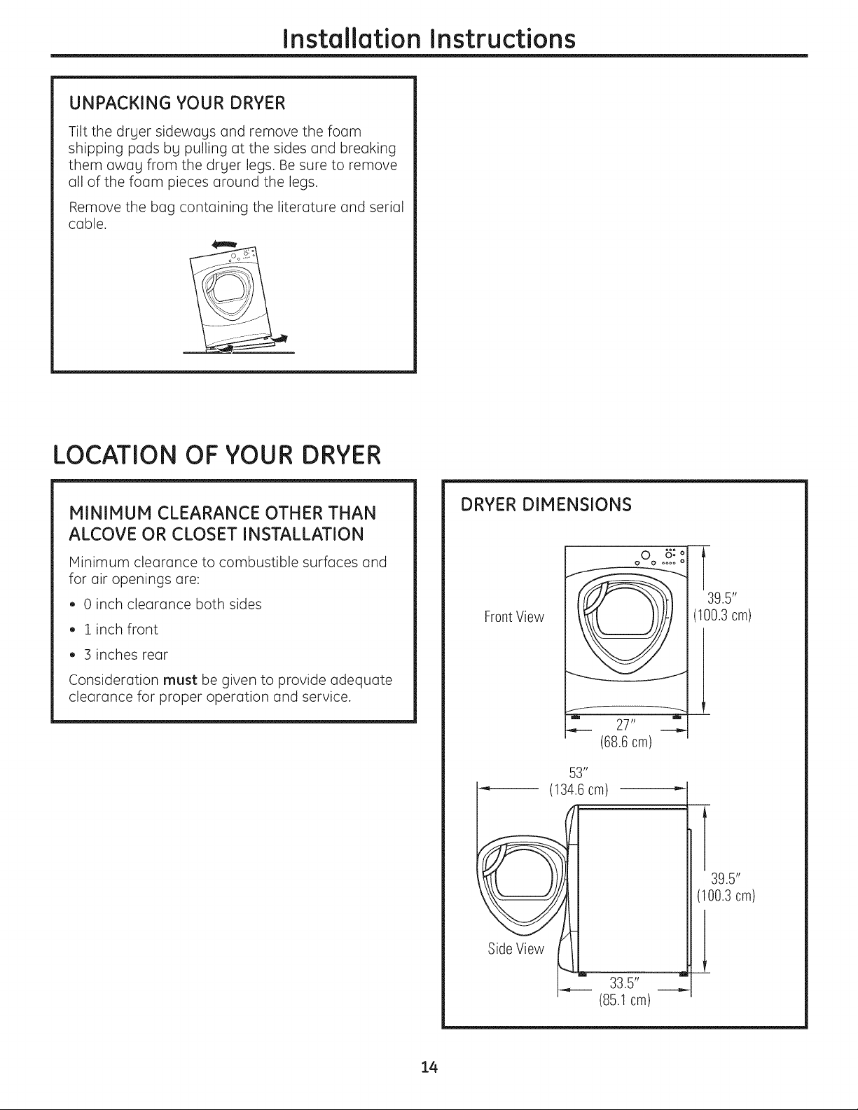
UNPACKING YOUR DRYER
Tilt the dryer sideways and remove the foam
shipping pads by pulling at the sides and breaking
them away from the dryer legs. Be sure to remove
all of the foam pieces around the legs.
Remove the bag containing the literature and serial
cable.
LOCATION OF YOUR DRYER
MINIMUM CLEARANCE OTHER THAN
ALCOVE OR CLOSET INSTALLATION
Minimum clearance to combustible surfaces and
for air openings are:
• 0 inch clearance both sides
• 1 inch front
• 3 inches rear
Consideration must be given to provide adequate
clearance for proper operation and service.
DRYER DIMENSIONS
FrontView
-il i
(68.6cm)
53"
(134.6cm)
oOo o: o
27"
oooo o
T
39.5"
(100.3 cm)
14
Side View
m m
33.5"
(85.1 cm)
39.5"
(100.3cm)
Installation Instructions
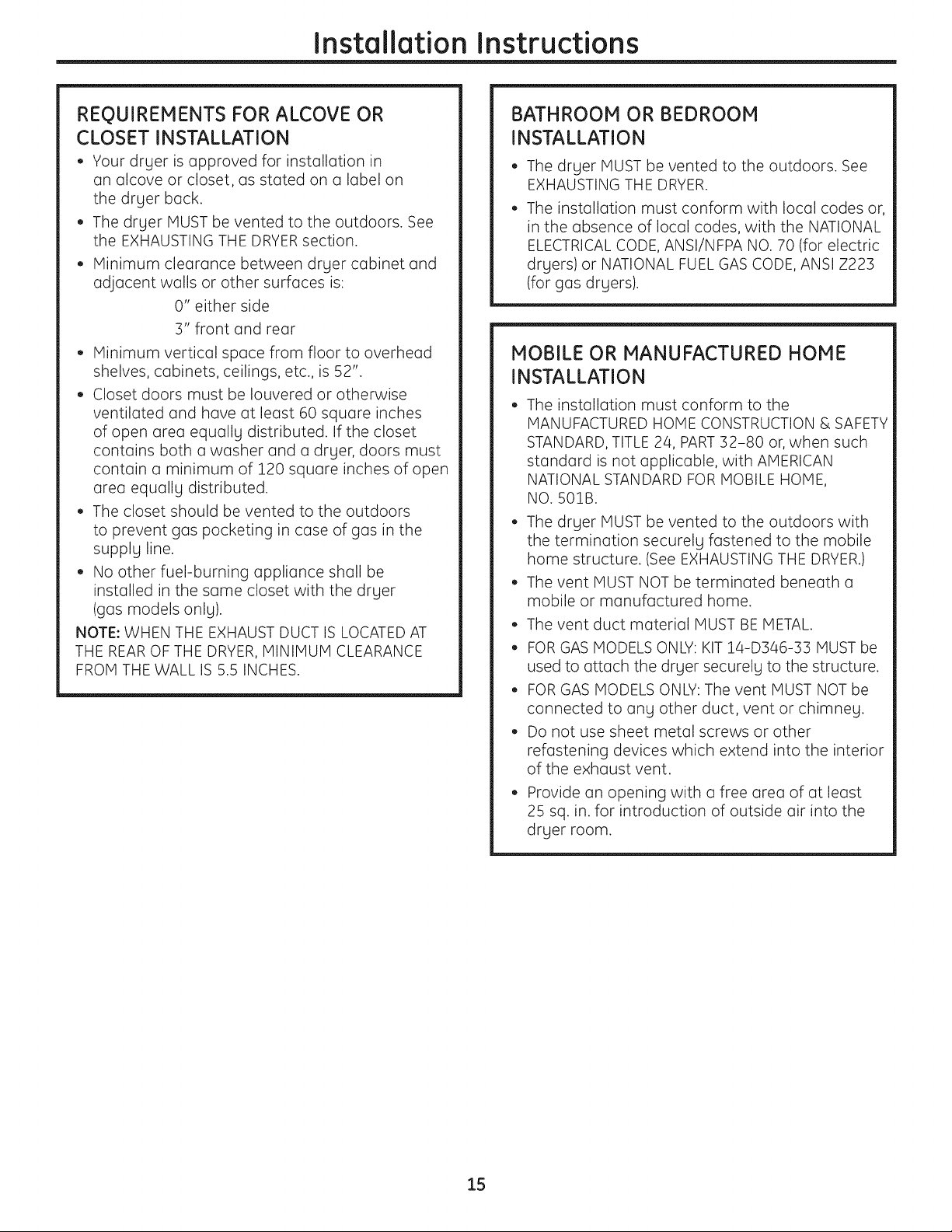
REQUIREMENTS FOR ALCOVE OR
CLOSET INSTALLATION
• Your dryer is approved for installation in
an alcove or closet, as stated on a label on
the dryer back.
• The dryer MUST be vented to the outdoors. See
the EXHAUSTING THE DRYERsection.
• Minimum clearance between dryer cabinet and
adjacent walls or other surfaces is:
0" either side
3" front and rear
• Minimum vertical space from floor to overhead
shelves, cabinets, ceilings, etc., is 52".
• Closet doors must be Iouvered or otherwise
ventilated and have at least 60 square inches
of open area equally distributed. If the closet
contains both a washer and a dryer, doors must
contain a minimum of 120 square inches of open
area equally distributed.
• The closet should be vented to the outdoors
to prevent gas pocketing in case of gas in the
supply line.
• No other fuel-burning appliance shall be
installed in the same closet with the dryer
(gas models only).
NOTE: WHEN THE EXHAUST DUCT IS LOCATEDAT
THE REAROF THE DRYER, MINIMUM CLEARANCE
FROM THE WALL IS 5.5 INCHES.
BATHROOM OR BEDROOM
INSTALLATION
• The dryer MUST be vented to the outdoors. See
EXHAUSTING THE DRYER.
• The installation must conform with local codes or,
in the absence of local codes, with the NATIONAL
ELECTRICALCODE, ANSI/NFPA NO. 70 (for electric
dryers) or NATIONAL FUEL GAS CODE, ANSI Z223
(for gas dryers).
MOBILE OR MANUFACTURED HOME
INSTALLATION
• The installation must conform to the
MANUFACTURED HOME CONSTRUCTION & SAFETY
STANDARD, TITLE 24, PART32-80 or, when such
standard is not applicable, with AMERICAN
NATIONAL STANDARD FOR MOBILE HOME,
NO. 501B.
• The dryer MUST be vented to the outdoors with
the termination securely fastened to the mobile
home structure. (See EXHAUSTING THE DRYER.)
• The vent MUST NOT be terminated beneath a
mobile or manufactured home.
• The vent duct material MUST BE METAL.
• FOR GAS MODELS ONLY: KIT 14-D346-33 MUST be
used to attach the dryer securely to the structure.
• FOR GAS MODELS ONLY: The vent MUST NOT be
connected to any other duct, vent or chimney.
• Do not use sheet metal screws or other
refastening devices which extend into the interior
of the exhaust vent.
• Provide an opening with a free area of at least
25 sq. in. for introduction of outside air into the
dryer room.
15

Installation Instructions
CONNECTING INLET HOSES
CONNECTING INLET HOSES
To produce steam, the dryer must connect to
the cold water supply. Since the washer must
also connect to the cold water, a "`7"connector
is inserted to allow both inlet hoses to make that
connection at the same time.
NOTE: Use the new inlet hoses provided; never
use old hoses.
, Turn the cold water faucet off. Remove the
washer inlet hose from the washer fill valve
connector (cold).
2. Ensure the rubber flat washer is in place and
screw the female coupling of the short hose
onto the washer fill valve connector. Tighten
by hand until firmly seated.
3. Attach the female end of the '"7" connector
to the male coupling of the short hose. Ensure
the rubber flat washer is in place. Tighten
by hand until firmly seated.
CONNECTING INLET HOSES (cont.}
7. Using pliers, tighten all the couplings with
an additional two-thirds turn.
NOTE: Do not overtighten. Damage to the couplings
may result.
8. Turn the water faucet on.
9. Check for leaks around the "`7" connector,
faucet and hose couplings.
4. Insert the filter screen in the coupling of the
washer's inlet hose. If a rubber flat washer
is already in place remove it before installing
the filter screen. Attach this coupling to one male
end of the "`7" connector. Tighten by hand until
firmly seated.
5. Ensure the rubber flat washer is in place and
attach the dryer's long inlet hose to the other
male end of the "'7" connector. Tighten by hand
until firmly seated.
,
Ensure the rubber flat washer is in place and
attach the other end of the dryer's long inlet
hose to the fill valve connector at the bottom
of the dryer back panel. Tighten by hand until
firmly seated.
WATER SUPPLY REQUIREMENTS
Hot and cold water faucets MUST be installed
within 42 in. (107 cm) of your washer's water inlet.
The faucets MUST be 3/4 in. (1.9 cm) garden
hose-type so inlet hoses can be connected. Water
pressure MUST be between 10 and 120 pounds
per square inch. Your water department can
advise you of your water pressure.
NOTE: A water softener is recommended to reduce
buildup of scale inside the steam generator
if the home water supply is very hard.
16
Installation Instructions
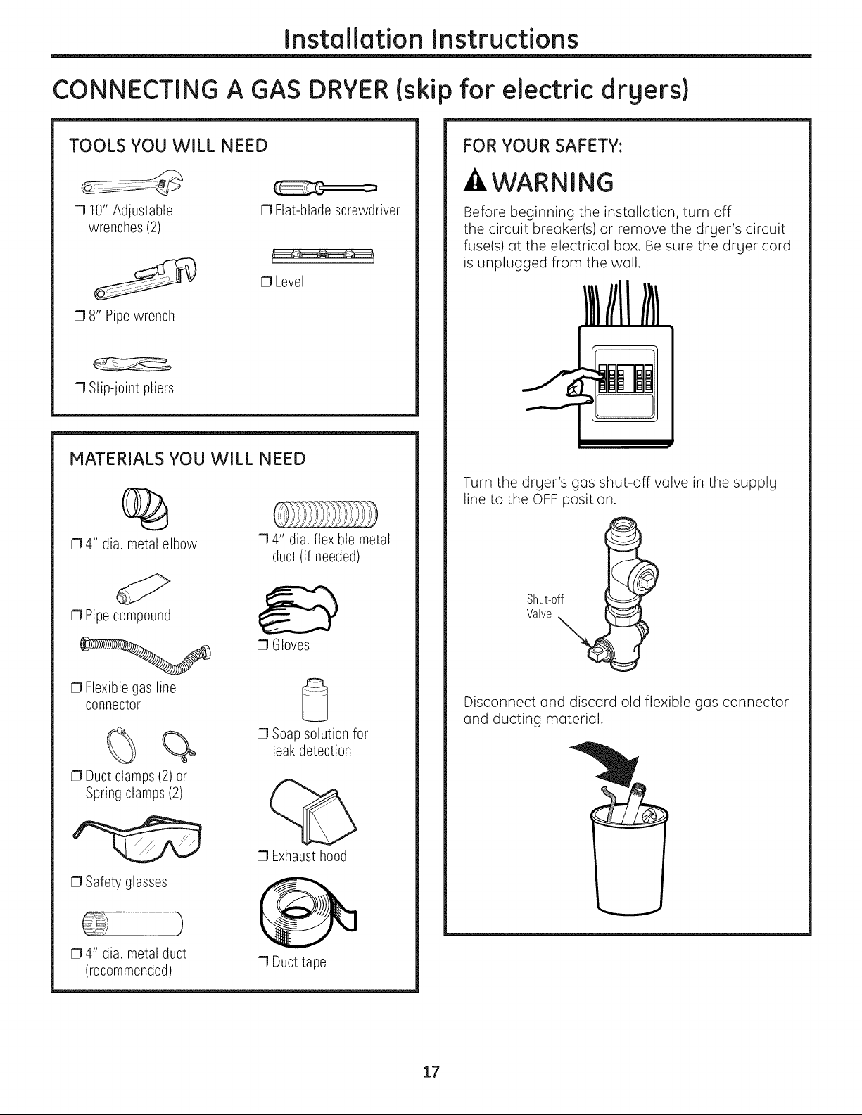
CONNECTING A GAS DRYER(skip for electric drgers}
TOOLS YOU WILL NEED
[] 10" Adjustable
wrenches (2)
[] 8" Pipewrench
[] Slip-joint pliers
[] Flat-blade screwdriver
[] Level
MATERIALS YOU WILL NEED
%
[] 4" dia. metal elbow
[] 4" dia. flexible metal
duct (if needed)
FOR YOUR SAFETY:
-&WARNING
Before beginning the installation, turn off
the circuit breaker(s) or remove the drger's circuit
fuse(s) at the electrical box. Be sure the drger cord
is unplugged from the wall.
Turn the drger's gas shut-off valve in the supplg
line to the OFF position.
[] Pipecompound
[] Flexible gas line
connector
%
[] Duct clamps (2) or
Spring clamps (2)
[] Safety glasses
[] 4" dia. metal duct
(recommended)
Shut-off
Valve
[] Gloves
Disconnect and discard old flexible gas connector
and ducting material.
[] Soap solution for
leakdetection
[] Exhaust hood
[] Duct tape
17
Installation Instructions
CONNECTING A GAS DRYER (cont.)
GAS REQUIREMENTS
WARNING
Installation must conform to local codes
and ordinances, or in their absence, the
NATIONAL FUEL GAS CODE, ANSI Z223.
• This gas dryer is equipped with a Valve and
Burner Assembly for use only with natural gas.
Using conversion kit 14-A048, your local service
organization can convert this dryer for use with
propane (LP)gas. ALL CONVERSIONS MUST BE
MADE BY PROPERLYTRAINED AND C.)UALIFIED
PERSONNEL AND IN ACCORDANCE WITH LOCAL
CODES AND ORDINANCE REQUIREMENTS.
• The dryer must be disconnected from the gas
supply piping system during any pressure testing
of that system at a test pressure in excess of
0.5 PSI(3.4 KPa).
The dryer must be isolated from the gas supply
piping system by closing the equipment shut-off
valve during any pressure testing of the gas
supply piping of test pressure equal to or less
than 0.5 PSI(3.4KPa).
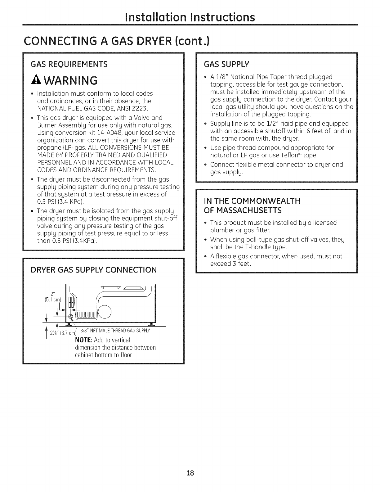
DRYER GAS SUPPLY CONNECTION
GAS SUPPLY
• A 1/8" National Pipe Taper thread plugged
tapping, accessible for test gauge connection,
must be installed immediately upstream of the
gas supply connection to the dryer. Contact your
local gas utility should you have questions on the
installation of the plugged tapping.
• Supply line is to be 1/2" rigid pipe and equipped
with an accessible shutoff within 6 feet of, and in
the same room with, the dryer.
• Use pipe thread compound appropriate for
natural or LP gas or use Teflon ®tape.
• Connect flexible metal connector to dryer and
gas supply.
IN THE COMMONWEALTH
OF MASSACHUSETTS
• This product must be installed by a licensed
plumber or gas fitter.
• When using ball-type gas shut-off valves, they
shall be the T-handle type.
• A flexible gas connector, when used, must not
exceed 3 feet.
12%" (6.7 om_308T"F?PAddlEoT;2;t_2_AS SUPPLY
dimensionthedistancebetween
cabinet bottom to floor.
18
Installation Instructions
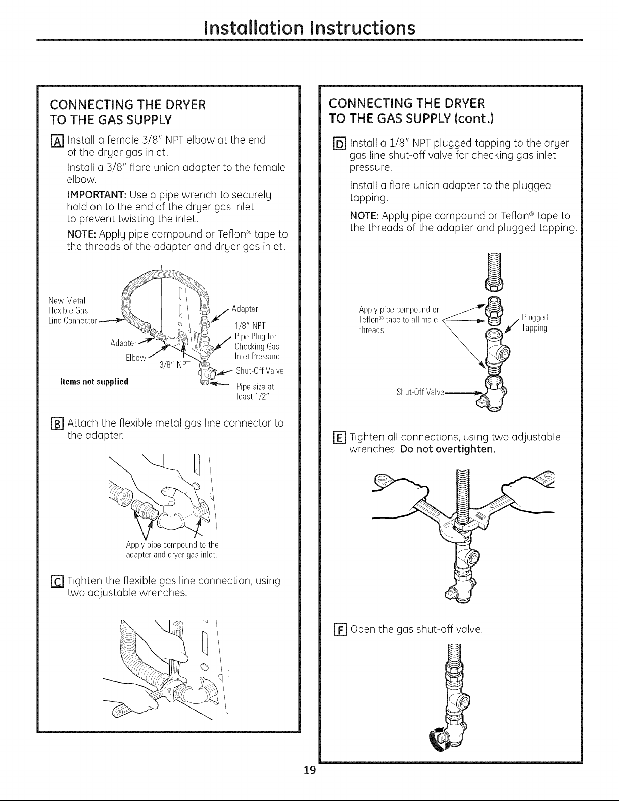
CONNECTING THE DRYER
TO THE GAS SUPPLY
r_ Install a female 3/8" NPT elbow at the end
of the dryer gas inlet.
Install a 3/8" flare union adapter to the female
elbow.
IMPORTANT: Use a pipe wrench to securely
hold on to the end of the dryer gas inlet
to prevent twisting the inlet.
NOTE: Apply pipe compound or Teflon ®tape to
the threads of the adapter and dryer gas inlet.
NewMetal __
FlexibleGas ,j Adapter
Line Connector.----__, _ __ 1/8" NPT
__., PipePlugfor
Adapter_ >_ _/IC_J CheckingGas
Elbowj ...... [_,.J Inlet Pressure
Ss'NPT Shut-OffValve
Items not supplied _-_"" Pipesize at
least1/2"
CONNECTING THE DRYER
TO THE GAS SUPPLY {cont.}
@Install a 1/8" NPT plugged tapping to the dryer
gas line shut-off valve for checking gas inlet
pressure.
Install a flare union adapter to the plugged
tapping.
NOTE: Apply pipe compound or Teflon ® tape to
the threads of the adapter and plugged tapping.
Applypipecompoundor __
Teflon®tapeto all male X_--------b_'_ / Plugged
threads. _ _t¢" Tapping
Shut-OffValve__ !
[] Attach the flexible metal gas line connector to
the adapter.
Apply pipe compound to the
adapter and dryer gas inlet.
[-C']Tighten the flexible gas line connection, using
two adjustable wrenches.
E] Tighten all connections, using two adjustable
wrenches. Do not overtighten.
r_ open the gas shut-off valve.
19
Installation Instructions
CONNECTING A GAS DRYER (cont.)
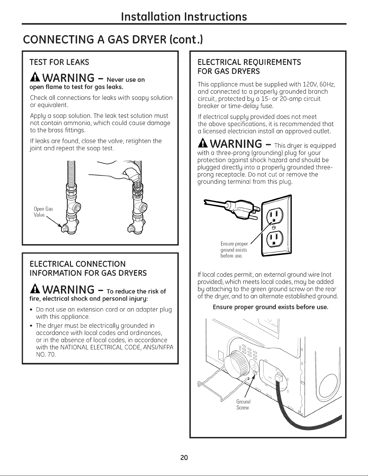
TEST FOR LEAKS
_k WARNING - Neverusean
open flame to test for gas leaks.
Check all connections for leaks with soapy solution
or equivalent.
Apply a soap solution. The leak test solution must
not contain ammonia, which could cause damage
to the brass fittings.
If leaks are found, close the valve, retighten the
joint and repeat the soap test.
OpenGas
Valve
ELECTRICAL REQUIREMENTS
FOR GAS DRYERS
This appliance must be supplied with 120V, 60Hz,
and connected to a properly grounded branch
circuit, protected by a 15- or 20-amp circuit
breaker or time-delay fuse.
If electrical supply provided does not meet
the above specifications, it is recommended that
a licensed electrician install an approved outlet.
-_WARNING - Thisdryer is equipped
witha three-prong(grounding)plugforyour
protectionagainstshock hazard and shouldbe
plugged directlyintoa properlygrounded three-
prong receptacle.Do not cutor remove the
groundingterminalfrom thisplug.
ELECTRICAL CONNECTION
INFORMATION FOR GAS DRYERS
WARNING - Toreducetheriskof
fire, electrical shock and personal injurg:
Do not use an extension cord or an adapter plug
with this appliance.
The dryer must be electrically grounded in
accordance with local codes and ordinances,
or in the absence of local codes, in accordance
with the NATIONAL ELECTRICALCODE, ANSI/NFPA
NO. 70.
Ensure proper
ground exists
before use.
If local codes permit, an external ground wire (not
provided), which meets local codes, may be added
by attaching to the green ground screw on the rear
of the dryer, and to an alternate established ground.
Ensure proper ground exists before use.
Ground
Screw
20
Installation Instructions
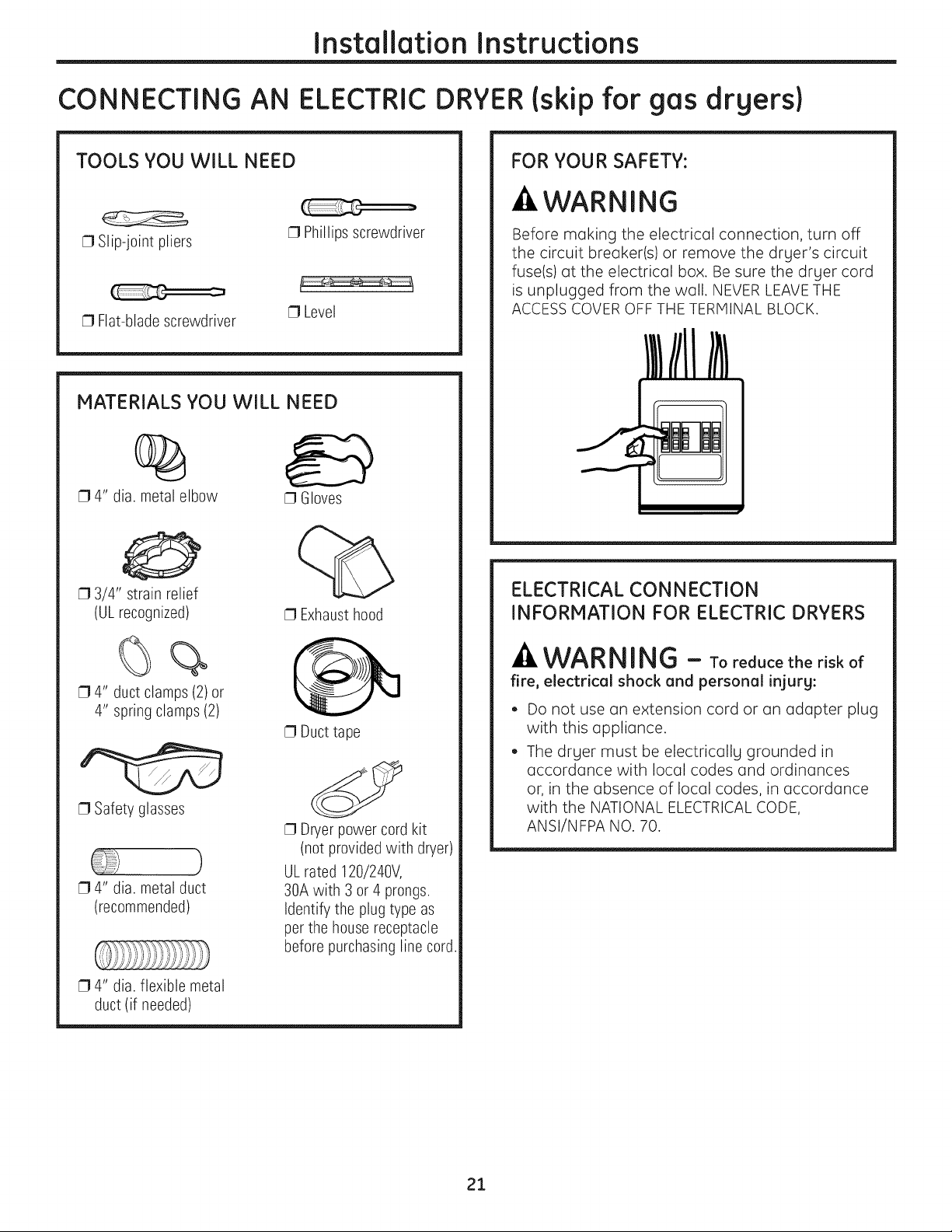
CONNECTING AN ELECTRICDRYER(skip for gas dryers}
TOOLS YOU WILL NEED
[] Slip-joint pliers
[] Flat-blade screwdriver
MATERIALS YOU WILL NEED
[] Phillips screwdriver
[] Level
%
[] 4" dia. metal elbow
[] Gloves
0
[] 3/4" strain relief
(ULrecognized)
[] Exhaust hood
FOR YOUR SAFETY:
-&WARNING
Before making the electrical connection, turn off
the circuit breaker(s) or remove the dryer's circuit
fuse(s) at the electrical box. Be sure the dryer cord
is unplugged from the wall. NEVER LEAVETHE
ACCESSCOVER OFF THE TERMINAL BLOCK.
ELECTRICAL CONNECTION
INFORMATION FOR ELECTRIC DRYERS
[] 4" duct clamps (2) or
4" spring clamps (2)
[] Safety glasses
[] 4" dia. metal duct
(recommended)
[] 4" dia. flexible metal
duct (if needed)
[] Duct tape
[] Dryer power cord kit
(not provided with dryer)
ULrated 120/240V,
30A with 3 or 4prongs.
Identify the plug type as
per the housereceptacle
before purchasing line cord.
-A WARNING - Toreducetheriskof
fire, electrical shock and personal injury:
• Do not use an extension cord or an adapter plug
with this appliance.
• The drger must be electricallg grounded in
accordance with local codes and ordinances
or, in the absence of local codes, in accordance
with the NATIONAL ELECTRICALCODE,
ANSI/NFPA NO. 70.
21
Installation Instructions
CONNECTING AN ELECTRIC DRYER {cont.)
ELECTRICAL REQUIREMENTS
FOR ELECTRIC DRYERS
This dryer must be connected to an individual
brunch circuit, protected by the required time-
delay fuses or circuit breakers. A three- or four-
wire, single-phase, 120/240V, 60Hz, 30-amp
circuit is required.
If the electric supply does not meet the above
specifications, then call a licensed electrician.
GROUNDING INSTRUCTIONS
This dryer must be connected to a grounded metal,
permanent wiring system, or an equipment-
grounding conductor must be run with the circuit
conductors and connected to the equipment
grounding terminal on the appliance.
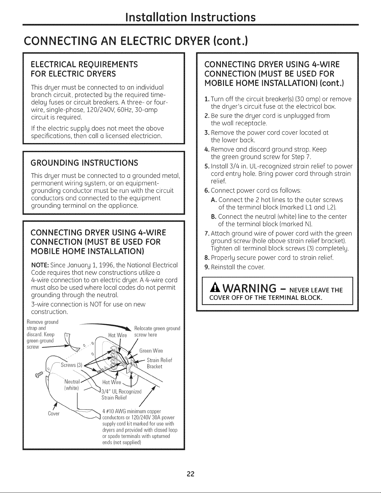
CONNECTING DRYER USING 4-WIRE
CONNECTION {MUST BE USED FOR
MOBILE HOME INSTALLATION}
NOTE: Since January 1, 1996, the National Electrical
Code requires that new constructions utilize a
4-wire connection to an electric dryer. A 4-wire cord
must also be used where local codes do not permit
grounding through the neutral.
3-wire connection is NOT for use on new
construction.
Removeground
strap and _ Relocate green ground
discard.Keep _ HotWire screwhere
green ground \t _ff _'_, I /
screw
_ /,_p£__"_ Green Wire
'_'_< __i_.._ - Strain Relief
_/-Screws(3} __,,. Bracket
CONNECTING DRYER USING 4-WIRE
CONNECTION {MUST BE USED FOR
MOBILE HONE INSTALLATION} {cont.}
.
Turn off the circuit breaker(s) (30 amp) or remove
the dryer's circuit fuse at the electrical box.
2.
Be sure the dryer cord is unplugged from
the well receptacle.
3.
Remove the power cord cover located at
the lower beck.
4.
Remove end discord ground strap. Keep
the green ground screw for Step 7.
5.
Install 3/4 in. UL-recognized strain relief to power
cord entry hole. Bring power cord through strain
relief.
.
Connect power cord us follows:
A. Connect the 2 hot lines to the outer screws
of the terminal block (marked L1 and L2).
B. Connect the neutral (white)line to the center
of the terminal block (marked N).
.
Attach ground wire of power cord with the green
ground screw (hole above strain relief bracket).
Tighten oil terminal block screws (3) completely.
.
Properly secure power cord to strain relief.
9.
Reinstall the cover.
WARNING - NEVERLEAVET,E
COVER OFF OF THE TERMINAL BLOCK.
" "-<_ 4#10 AWGminimumcopper
Lcvsr _-_',,_ conductors or 120/240V 30A power
supplycordkit markedfor usewith
dryersandprovidedwith closedloop
or spade terminals with upturned
ends (not supplied)
22
Installation Instructions
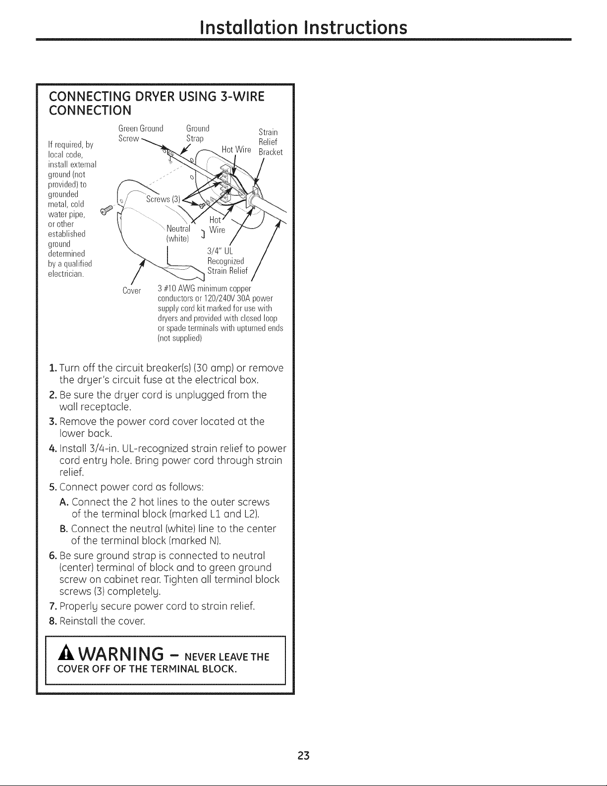
CONNECTING DRYER USING 3-WIRE
CONNECTION
GreenGround Ground Strain
Ifrequired,by
localcode,
installexternal
ground(not
provided)to
grounded
metal,cold
water pipe,
or other
established
ground
determined
bya qualified
electrician.
Screw Strap Relief
HotWire Bracket
Screws
Neutral Wire
(white) _]
3/4" UL
Recognized
StrainRelief
Cover
3#10AWGminimumcopper
conductorsor 120/240V30Apower
supplycordkit markedfor usewith
dryersandprovidedwith closedloop
or spadeterminalswith upturnedends
(notsupplied)
1.Turn off the circuit breaker(s) (30 amp) or remove
the dryer's circuit fuse at the electrical box.
2. Be sure the dryer cord is unplugged from the
well receptacle.
3. Remove the power cord cover located at the
lower beck.
4. Install 3/4-in. UL-recognized strain relief to power
cord entry hole. Bring power cord through strain
relief.
5. Connect power cord as follows:
A. Connect the 2 hot lines to the outer screws
of the terminal block (marked L1 and L2).
B. Connect the neutral (white)line to the center
of the terminal block (marked N).
6. Be sure ground strop is connected to neutral
(center) terminal of block and to green ground
screw on cabinet rear. Tighten oil terminal block
screws (3) completely.
7. Properly secure power cord to strain relief.
8. Reinstall the cover.
WARNING - NEVERLEAVETNE
COVER OFF OF THE TERMINAL BLOCK.
23
Installation Instructions
EXHAUSTING THE DRYER
WARNING - Toreducethe
risk of fire or personal injury:
• This dryer must be exhausted to the outdoors.
• Use only metal duct.
• Do not terminate exhaust into a chimney, any
gas vent, under an enclosed floor, in a crawl
space, wall, ceiling, into an attic or other
concealed space of a building. The accumulated
lint could create a fire hazard.
• Provide an access for inspection and cleaning
of the exhaust system, especially at turns.
Inspect and clean at least once a year.
• Never terminate the exhaust into a common
duct with a kitchen exhaust. A combination
of lint and grease could create o fire hazard.
• Do not obstruct incoming or exhausted air.
• This dryer comes ready for rear exhausting.
If space is limited, use the instructions
on pages 28-30 to exhaust directly
from the sides or bottom of the cabinet.
EXHAUST SYSTEM CHECKLIST
HOOD OR WALL CAP
Terminate in a manner to prevent back drafts or
entry of birds or other wildlife.
Termination should present minimal resistance to
the exhaust airflow and should require little or no
maintenance to prevent clogging.
®
Never install a screen in or over the exhaust duct.
®
Wall caps must be installed at least 12" above
ground level or any other obstruction with the
opening pointed down.
If roof vents or Iouvered plenums are used, they
must be equivalent to a 4" dampened wall cap in
regard to resistance to airflow, prevention of back
drafts and maintenance required to prevent
clogging.
SEPARATION OF TURNS
• For best performance, separate all turns by
at least 4 ft. of straight duct, including distance
between last turn and dampened wall cap.
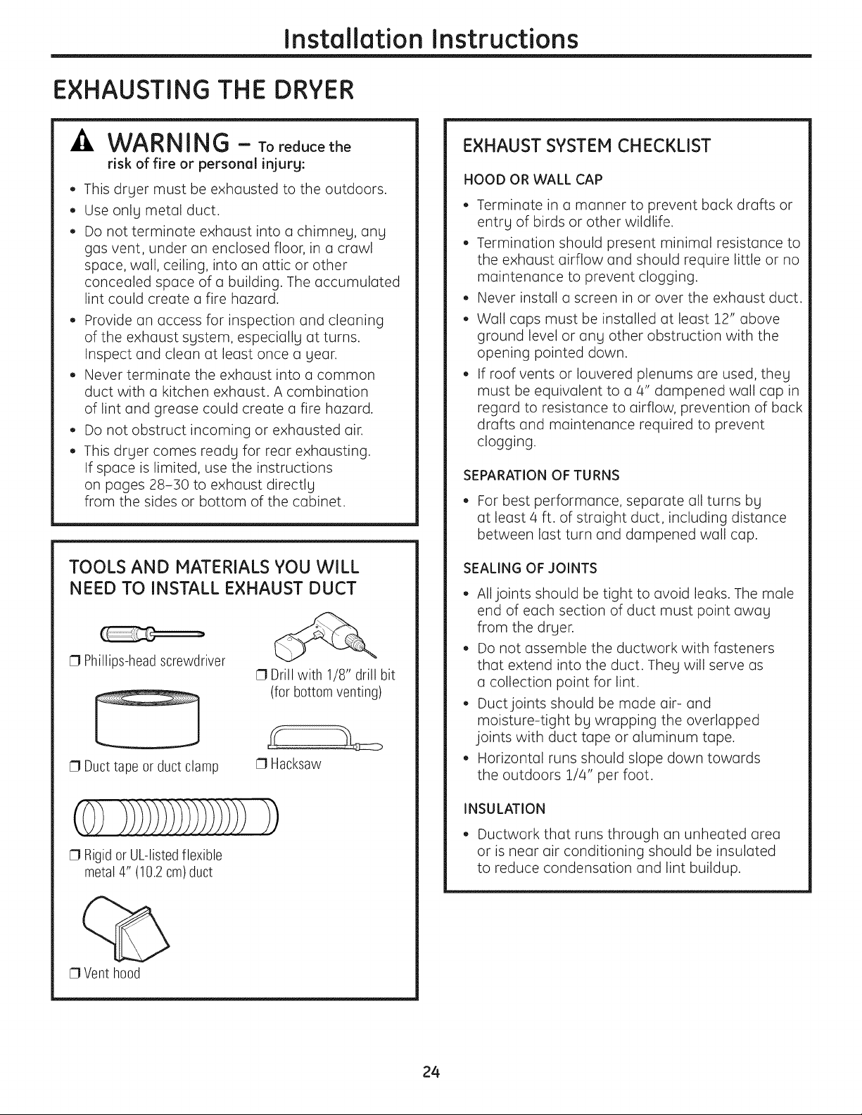
TOOLS AND MATERIALS YOU WILL
NEED TO INSTALL EXHAUST DUCT
[] Phillips-head screwdriver
[] Duct tape or ductclamp
[] Drill with 1/8" drill bit
(for bottom venting)
[] Hacksaw
(0)))i)))))))))))))))
[] Rigid or UL-listed flexible
metal 4" (10.2 cm)duct
[] Vent hood
SEALING OF JOINTS
• All joints should be tight to avoid leaks. The male
end of each section of duct must point away
from the dryer.
• Do not assemble the ductwork with fasteners
that extend into the duct. They will serve as
a collection point for lint.
• Duct joints should be made air- and
moisture-tight by wrapping the overlapped
joints with duct tape or aluminum tape.
• Horizontal runs should slope down towards
the outdoors 1/4" per foot.
INSULATION
• Ductwork that runs through an unheated area
or is near air conditioning should be insulated
to reduce condensation and lint buildup.
24
Installation Instructions
USING FLEXIBLE METAL DUCT
FOR TRANSITION VENTING
Rigid or semi-rigid metal ducting is
recommended for use as transition ducting
between the dryer and the wall. In special
installations when it is impossible to make a
connection with the above recommendations, then
a UL-listed flexible metal transition duct mall be
used between the drLler and wall connection onlLI.
The use of this ducting will affect drLI time. OnlLI
those foil-type flexible ducts, if any, specificallLI
identified for use with the appliance by the
manufacturer should be used. In the United States,
the duct must comply with the Outline for Clothes
Drger Transition Duct, Subject 2158A.
If flexible metal transition duct is necessarLI,
the following directions must be followed:
• Use the shortest length possible. The total length
of flexible metal duct shall not exceed 2.4 m.
• Stretch the duct to its maximum length.
• Do not crush or collapse.
• Never use flexible metal ducting inside the wall
or inside the drLler.
• Avoid resting the duct on sharp objects.
• Venting must conform to local building codes.
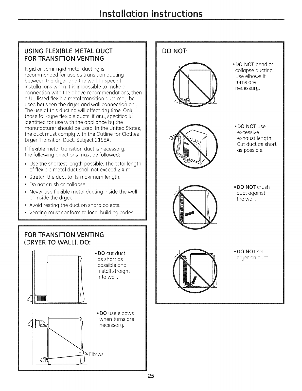
DO NOT:
• DO NOT bend or
collapse ducting.
Use elbows if
turns are
necessarLI.
• DO NOT use
excessive
exhaust length.
Cut duct as short
as possible.
• DO NOT crush
duct against
the wall.
FOR TRANSITION VENTING
(DRYER TO WALL}, DO:
• DO cut duct
4
Elbows
as short as
possible and
install straight
into wall.
• DO use elbows
when turns are
necessarg.
• DO NOT set
drger on duct.
25
Installation Instructions
EXHAUSTING THE DRYER IcontJ
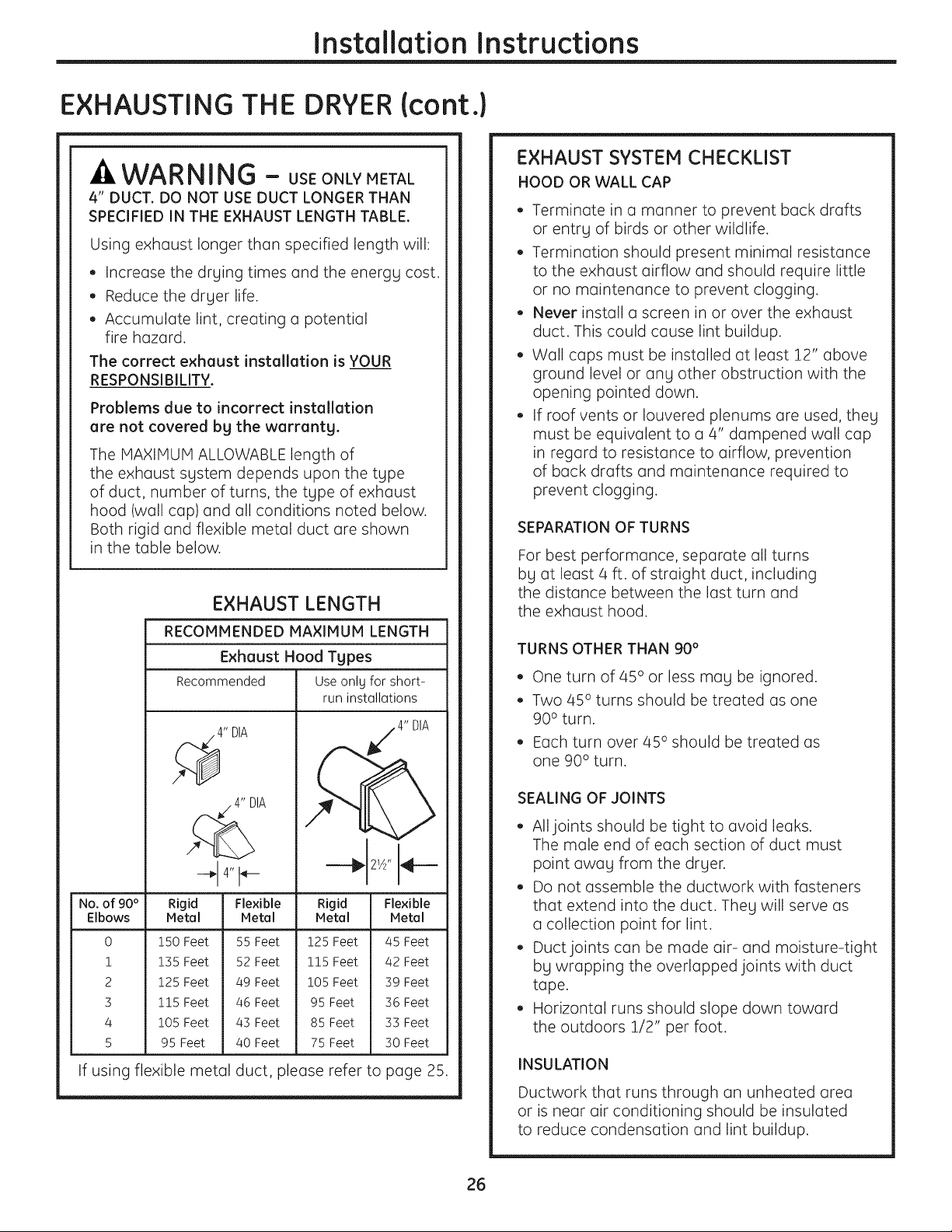
WARNING - USEONLYMETAL
4" DUCT. DO NOT USE DUCT LONGER THAN
SPECIFIED IN THE EXHAUST LENGTH TABLE.
Using exhaust longer than specified length will:
• Increase the drging times and the energg cost.
• Reduce the drger life.
• Accumulate lint, creating a potential
fire hazard.
The correct exhaust installation is YOUR
RESPONSIBILITY.
Problems due to incorrect installation
are not covered bg the warrantg.
The MAXIMUM ALLOWABLE length of
the exhaust sgstem depends upon the tgpe
of duct, number of turns, the tgpe of exhaust
hood (wall cap) and all conditions noted below.
Both rigid and flexible metal duct are shown
in the table below.
EXHAUST LENGTH
RECOMMENDED MAXIMUM LENGTH
Exhaust Hood Types
Recommended Useonly for short-
run installations
EXHAUST SYSTEM CHECKLIST
HOOD OR WALL CAP
• Terminate in a manner to prevent back drafts
or entrg of birds or other wildlife.
• Termination should present minimal resistance
to the exhaust airflow and should require little
or no maintenance to prevent clogging.
• Never install a screen in or over the exhaust
duct. This could cause lint buildup.
• Wall caps must be installed at least 12" above
ground level or ang other obstruction with the
opening pointed down.
• If roof vents or Iouvered plenums are used, theg
must be equivalent to a 4" dampened wall cap
in regard to resistance to airflow, prevention
of back drafts and maintenance required to
prevent clogging.
SEPARATION OF TURNS
For best performance, separate all turns
bg at least 4 ft. of straight duct, including
the distance between the last turn and
the exhaust hood.
TURNS OTHER THAN 90 °
• One turn of 45° or less mag be ignored.
• Two 45° turns should be treated as one
90 ° turn.
• Each turn over 45° should be treated as
one 90° turn.
4" DIA
No. of 90 ° Rigid Flexible Rigid Flexible
Elbows Metal Metal Metal Metal
0
!
2
3
4
5
150 Feet
135 Feet
125 Feet
115 Feet
105 Feet
95 Feet
55 Feet 125 Feet
52 Feet 115 Feet
49 Feet 105 Feet
46 Feet 95 Feet
43 Feet 85 Feet
40 Feet 75 Feet
45 Feet
42 Feet
39 Feet
36 Feet
33 Feet
30 Feet
If using flexible metal duct, please refer to page 25.
SEALING OF JOINTS
• All joints should be tight to avoid leaks.
The male end of each section of duct must
point awag from the drger.
• Do not assemble the ductwork with fasteners
that extend into the duct. Theg will serve as
a collection point for lint.
• Duct joints can be made air- and moisture-tight
bg wrapping the overlapped joints with duct
tape.
• Horizontal runs should slope down toward
the outdoors 1/2" per foot.
INSULATION
Ductwork that runs through an unheated area
or is near air conditioning should be insulated
to reduce condensation and lint buildup.
26
Installation Instructions
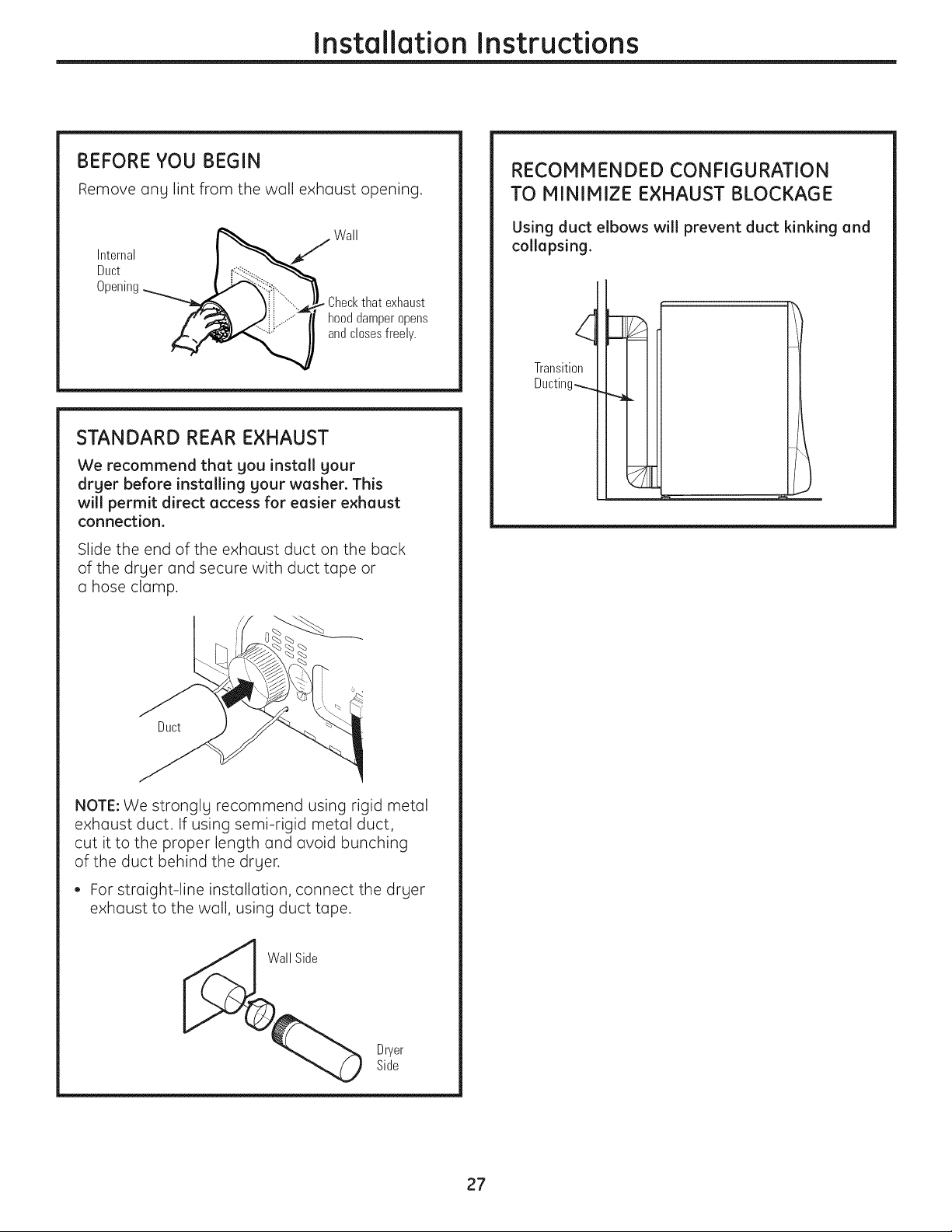
BEFORE YOU BEGIN
Remove ang lint from the wall exhaust opening.
Wall
Internal I _J
Duct I _ ........"_----------------_
Opening_:_i,,.
¥i - ..... Checkthat exhaust
f',_ .i,/:.- ..........." hood damper opens
andclosesfreely.
STANDARD REAR EXHAUST
We recommend that you install your
dryer before installing your washer. This
will permit direct access for easier exhaust
connection.
Slide the end of the exhaust duct on the back
of the drger and secure with duct tape or
a hose clamp.
RECOMMENDED CONFIGURATION
TO MINIMIZE EXHAUST BLOCKAGE
Using duct elbows will prevent duct kinking and
collapsing.
Transition
Ducting_
Duct
NOTE: We stronglg recommend using rigid metal
exhaust duct. If using semi-rigid metal duct,
cut it to the proper length and avoid bunching
of the duct behind the drger.
• For straight-line installation, connect the drger
exhaust to the wall, using duct tape.
Dryer
Side
27

Installation Instructions
EXHAUSTING THE DRYER (cont.)
SIDE VENTING:
Dryer Exhaust to right of cabinet for Electric
models only.
Dryer Exhaust to left of cabinet for Gas and
Electric models.
WARNING - BEFORE
PERFORMING THIS EXHAUST INSTALLATION,
BE SURE TO DISCONNECT THE DRYER FROM ITS
ELECTRICAL SUPPLY. PROTECT YOUR HANDS
AND ARMS FROM SHARP EDGES WHEN
WORKING INSIDE THE CABINET. BE SURE
TO WEAR GLOVES.
Remove
screw
and save
\
Detach and remove the bottom, right or left side
knockout as desired. Remove the screw inside the
drger exhaust duct and save. Pull the duct out of
the drger.
Right
Left
Bottom
Removedesired
knockout(oneonly)
ADDING A NEW DUCT
Fixinghole Portion"A"
.' 1%4 :
L
exhaust
Reconnect the cut portion (A)of the duct to the
blower housing. Make sure that the shortened duct
is aligned with the tab in the base. Use the screw
saved previously to secure the duct in place
through the tab on the appliance base.
ADDING ELBOW AND DUCT FOR EXHAUST
TO LEFT OR RIGHT SIDE OF CABINET
Internalduct
Rearopening
• Insert the 4" elbow through the rear opening and
connect the elbow to the drger internal duct.
Fixinghole
\
I_ 13sA''
Cut the duct as shown and keep portion A.
TAB LOCATION
Notfor gas
Bendtab
up45°
Through the rear opening, locate the tab in the
middle of the appliance base. Lift the tab to about
45°,using a flat-blade screwdriver.
Sideopening
• Insert the 4" duct through the side opening
and connect it to the elbow.
CAUTION: Do not pullor demege the
electricel wires end do not remove the vingl cover
from the electricel components inside the drger
when inserting the duct. A slight interference
meg occur between the e×heust end the wire
components.
28
Installation Instructions
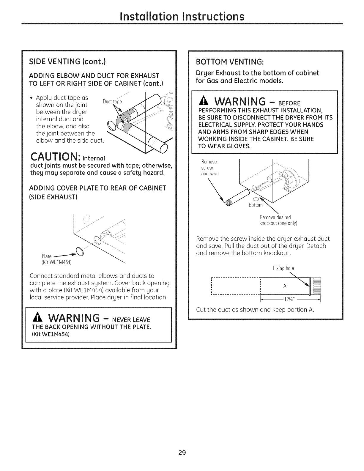
SIDE VENTING (cont.)
ADDING ELBOW AND DUCT FOR EXHAUST
TO LEFT OR RIGHT SIDE OF CABINET (cont.)
• Apply duct tape as
shown on the joint
between the dryer
internal duct and
the elbow, and also
the joint between the "
elbow and the side duct.
Duct
CAUTION: Internal
duct joints must be secured with tape; otherwise,
theg mag separate and cause a safetg hazard.
ADDING COVER PLATE TO REAR OF CABINET
(SIDE EXHAUST)
BOTTOM VENTING:
Drger Exhaust to the bottom of cabinet
for Gas and Electric models.
-A WAR NING - BEFORE
PERFORMING THIS EXHAUST INSTALLATION,
BE SURE TO DISCONNECT THE DRYER FROM ITS
ELECTRICAL SUPPLY. PROTECT YOUR HANDS
AND ARMS FROM SHARP EDGES WHEN
WORKING INSIDE THE CABINET. BE SURE
TO WEAR GLOVES.
Remove
screw
and save
X,
Bottom
Removedesired
knockout(oneonly)
Connect standard metal elbows and ducts to
complete the exhaust system. Cover back opening
with a plate (Kit WEIM454) available from your
local service provider. Place dryer in final location.
-A WARNING - NEVERLEAVE
THE BACK OPENING WITHOUT THE PLATE.
(Kit WEIM454)
Remove the screw inside the dryer exhaust duct
and save. Pull the duct out of the dryer. Detach
and remove the bottom knockout.
Fixinghole
..................... A
123A'' _I
Cut the duct as shown and keep portion A.
29
Installation Instructions
EXHAUSTING THE DRYER (cont.)
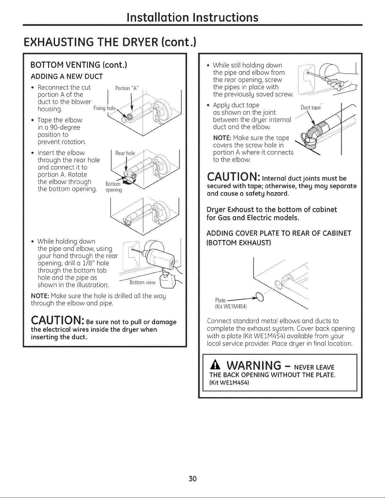
BOTTOM VENTING (cont.}
ADDING A NEW DUCT
Reconnect the cut
portion A of the
duct to the blower
housing,
Tape the elbow
in a 90-degree
position to
prevent rotation.
Insert the elbow
through the rear hole
and connect it to
portion A. Rotate
the elbow through
the bottom opening.
While holding down
the pipe and elbow, using
your hand through the rear
opening, drill a 1/8" hole
through the bottom tab
hole and the pipe as
shown in the illustration.
Fixinghole
Portion"A"
Rearhole
Bottom
opening
While still holding down
the pipe and elbow from
the rear opening, screw
the pipes in place with
the previously saved screw.
Apply duct tape Ducttape
as shown on the joint _ _<"
between the drger internal
duct and the elbow.
NOTE: Make sure the tape
covers the screw hole in
portion A where it connects
to the elbow.
CAUTION: Internalductjoints mustbe
secured with tape; otherwise, theg mag separate
and cause a safetghazard.
Dr£1er Exhaust to the bottom of cabinet
for Gas and Electric models.
ADDING COVER PLATE TO REAR OF CABINET
(BOTTOM EXHAUST)
Bottomview
NOTE: Make sure the hole is drilled all the wag
through the elbow and pipe.
CAUTION: Be sure not to pullor damage
the electrical wires inside the drger when
inserting the duct.
Connect standard metal elbows and ducts to
complete the exhaust sgstem. Cover back opening
with a plate (Kit WE1M454) available from gour
local service provider. Place drger in final location.
WARNING - NEVERLEAVE
THE BACK OPENING WITHOUT THE PLATE.
(Kit WEIM454)
3O
 Loading...