

Page 1
o
CL
ge.com
Safety Instructions ........... 2-4
Operating Instructions
Controls ........................... 5-8
Cycle Options .................... 9, 10
Drger Features .................. 10, 11
Quick Start Guide .................... 5
Settings Option ..................... 10
Using the Drger ..................... 12
Installation Instructions
Before You Begin ................ 13, 14
Connecting the Inlet Hoses ......... 16
Connecting a Gas Drger ........ 17-20
Connecting an
Electric Drger ................... 21-23
Exhausting the Drger ........... 24-30
Final Setup .......................... 31
Installing the Pedestal .......... 41-43
Location of gour Drger .......... 14, 15
Reversing the Door Swing ...... 32-37
Stacking the Washer
and Drger ....................... 38-40
Troubleshooting Tips ...... 44-47
DPVH890
UPVH890
S cheuses
Profile
La section frangaise commence 5 la page 51
Secadoras
Profile
La secci6n en espa_ol empieza en la p6gina 101
Consumer Support
Consumer Support ....... Back Cover
Warrantg (Canada) ................. 50
Warrantg (U.S.)..................... 49
SAVETHESEINSTRUCTIONS
Write the model and serial
numbers here:
Model #
Serial #
Theg are on the label on the front
of the drger behind the door.
175D1807P622 49-90354 09-08 JR
Page 2
IMPORTANT SAFETY INFORMATION.
READ ALL INSTRUCTIONS BEFORE USING.
WARNING!
For your safety, the information in this manual must be followed to minimize the risk
of fire or explosion, electric shock, or to prevent property damage, personal injury,
or death.
[] Do not store or use gasoline or other
flammable vapors and liquids in the
vicinity of this or any other appliance.
[] Installation and service must be
performed by a qualified installer,
service agency or the gas supplier.
WHAT TO DO IF YOU SMELL GAS:
[] Do not try to light a match, or
agarette, or turn on any gas or
electrical appliance.
[_ Do not touch any electrical switch;
do not use any phone in your building.
[-_ Clear the room, building or area
of all occupants.
California Safe Drinking Water and Toxic Enforcement Act
Thisact requires the governor of Californiato publish a list of substances known to the state to cause cancer,
birth defects or other reproductive harm and requires businessesto warn customers of potential exposureto
such substances.
Gasappliancescan cause minor exposuretofour of thesesubstances,namely benzene,carbon monoxide,
formaldehyde and soot, causedprimarily by the incompletecombustion of natural gasor LPfuels.
Properly adjusted dryers will minimize incomplete combustion. Exposureto these substances can be
minimized further by properly venting the dryer to the outdoors.
[_ Immediately call your gas supplier
from a neighbor's phone. Follow the
gas supplier's instructions carefully.
[_ If you cannot reach your gas supplier,
call the fire department.
%
2
PROPERINSTALLATION
This dryer must be properly installed and located in accordance with the Installation Instructions
before it is used. Installation Instructions are included in the back of this manual.
m Properlyground dryer to conform with all Exhaust/Ducting
governing codes and ordinances. Follow details
in Installation Instructions.
m
Installor store where itwill not be exposed to
temperatures below freezing or exposed to water
or weather.
m Connectto a properly rated, protected and sized
power supply circuit to avoid electrical overload.
m Removeall sharp packing items and disposeof
all shipping materials properly.
r_] DryersMUSTbe exhausted to the outside to
prevent large amounts of moisture and lint from
being blown into the room.
r_--]use only rigid metal4" diameter ductwork inside
the dryer cabinet. Useonly rigid metal or flexible
metal/4-in diameter ductwork for exhausting to
the outdoors. Neveruse plasticor other
combustible, easy-to-puncture ductwork.
Forcomplete details,follow the Installation
Instructions.
Page 3
WARNING!
YOUR LAUNDRY AREA
m
Keepthe area underneath and around your
appliances free of combustible materials,
(lint, paper,rags,etc.),gasoline, chemicals
and other flammable vapors and liquids.
m
Keepthe floor around your appliances clean
and dry to reduce the possibility of slipping.
m
Closesupervisionis necessary ifthis appliance is
used by or near children. Do not allow children to
play on,with or inside this or any other appliance.
WHEN USING YOUR DRYER
m
Neverreach into the dryer while the drum is
moving. Beforeloading, unloading or adding
clothes,wait until the drum has completely
stopped.
m
Cleanthe lint filter before each load to prevent lint
accumulation inside the dryer or inthe room. DO
NOTOPERATETHEDRYERWITHOUTTHELINT
FILTERIN PLACE.
m
Donot wash or dry articles that hove been
cleaned in,washed in,soaked in or spotted
with combustible or explosive substances(suchas
wax, oil,point, gasoline, degreosers,dry-cleaning
solvents,kerosene,etc.).Thesesubstances give
off vapors that may igniteor explode. Donot add
these substances to the wash water. Donot use
or place these substancesaround your washer
or dryer during operation.
m
Donot place items exposed to cooking oils in
your dryer. Items contaminated with cooking oils
may contribute to a chemical reaction that could
cause a clothes load to catch fire.
m
Any article on which you have used a cleaning
solvent or that contains flammable materials
(suchas cleaning cloths, mops,towels used in
beauty salons, restaurants or barber shops,etc.)
must not be placed in or near the dryer until
solvents or flammable materials have been
removed.There are many highly flammable items
used in homes such asacetone, denatured alcohol,
gasoline, kerosene,somehousehold cleaners,some
spot removers,turpentines, waxes, wax removers
and products containing petroleum distillates.
ge.com
m
Keepthe area around the exhaust opening
and adjacent surrounding areas freefrom the
accumulation of lint, dust and dirt.
m
Keepall laundry aids (suchas detergents,
bleaches,etc.)out of the reach of children,
preferably in a locked cabinet. Observeall
warnings on container labels to avoid injury.
m Neverclimb on or stand on the dryer top.
m
Thelaundry process can reduce the flame
retardancy of fabrics. Toavoid such a result,
carefully follow the garment manufacturer's
care instructions.
m
Donot dry articles containing rubber,plastic
or similar materials such as padded bras,tennis
shoes,galoshes, bath mats, rugs, bibs,baby pants,
plastic bags, pillows,etc.that may melt or burn.
Somerubber materials, when heated, can under
certain circumstances produce fire by spontaneous
combustion.
m
Donot store plastic, paper orclothing that may
burn or melt on top ofthe dryer during operation.
m
Garments labeled Dr_lAwa_lfrom Heat or DoNot
TumbleDry (suchas lifejackets containing Kapok)
must not be put in your dryer.
m
Donot dry fiberglass articles in your dryer.
Skinirritation could result from the remaining
particles that may be picked up by clothing
during subsequent dryer uses.
m
Tominimize the possibility of electric shock, unplug
this appliance from the power supply ordisconnect
the dryer at the householddistribution panel by
removing the fuse or switching off the circuit
breaker before attempting any maintenance or
cleaning (exceptthe removal and cleaning of the
lint filter).NOTE:PressingSTART/PAUSEor POWER
doesNOTdisconnect the appliance from the power
supply.
m
Ifyou seewater on the floor around the dryer,
callfor service.
Page 4
IMPORTANT SAFETY INFORMATION.
READ ALL INSTRUCTIONS BEFORE USING.
WARNING!
WHEN USING YOUR DRYER(cont.)
m
Neverattempt to operate this appliance if itis
damaged, malfunctioning, partiallg disassembled,
or has missing or broken parts, including a
damaged cord or plug. m
m
Theinterior of the machine and the exhaust duct
connection insidethe dryer should be cleaned at
least once a gearbg a qualified technician. See
the Sorting and Loading Hintssection on page 12.
m
Ifyours is a gas drger,it isequipped with an
automatic electric ignition and does not have
a pilot light. DO NOTATTEMPTTOLIGHTWITH
A MATCH.Burnsmag result from having gour hand
in the vicinity ofthe burner when the automatic
ignition turns on.
m
Donot open the drger door during steam cgcles.
Thesteam is verg hot and itwill continue to
exhaust from the port for severalseconds after
opening. Donot touch the steam port after a
steam cgcle.
m
Donot use a steam cgcle with items such
aswool, leather,silk,lingerie, foam products
or electric blankets.
Donot use steam cgcleson new clothes without
first washing.
Youmag wish to soften gour laundered fabrics
or reduce the static electricitg in them bgusing
a drger-applied fabric softener or an anti-static
conditioner.We recommend gou useeither
a fabric softener inthe wash cgcle,according
to the manufacturer's instructions for those
products, or trg a drger-added product for which
the manufacturer giveswritten assurance on
the package that their product can be safelg
used in gour drger.Serviceor performance
problems caused bg use of these products are
the responsibilitg ofthe manufacturers of those
products and are not covered under the warrantg
of this appliance.
m
Neverattempt to use the Steam Dewrinkleor
Steam Refreshcgcleswithout clothes in the drum.
Additionallg, it ishighlg recommended to select
the appropriate load sizefor best results.Selecting
large load cgclesfor small loads mag result in
wetting of clothes, and selecting small loadcgcles
for large loads mag result in poor dewrinkling
performance.
WHEN NOT USING YOURDRYER
m
Graspthe plug firmlg when disconnecting this
appliance to avoid damage to the cord while
pulling. Placethe cord awag from traffic areas
so itwill not be stepped on, tripped over or
subjected to damage.
m
Donot attempt to repair or replace ang part of
this appliance or attempt ang servicingunless
specificallgrecommended in this Owner's Manual
or in publisheduser-repair instructionsthat gou
understand and havethe skillsto carrg out.
_lE S
FOLLOWTHISSA TV/NFORM, T/ONO R ULLV.
I_'\_ SAVE THESE INSTRUCTIONS
m Beforediscarding a drger,or removing it from
service,remove the drger door to prevent children
from hiding inside.
m Do not tamper with controls.
4
Page 5
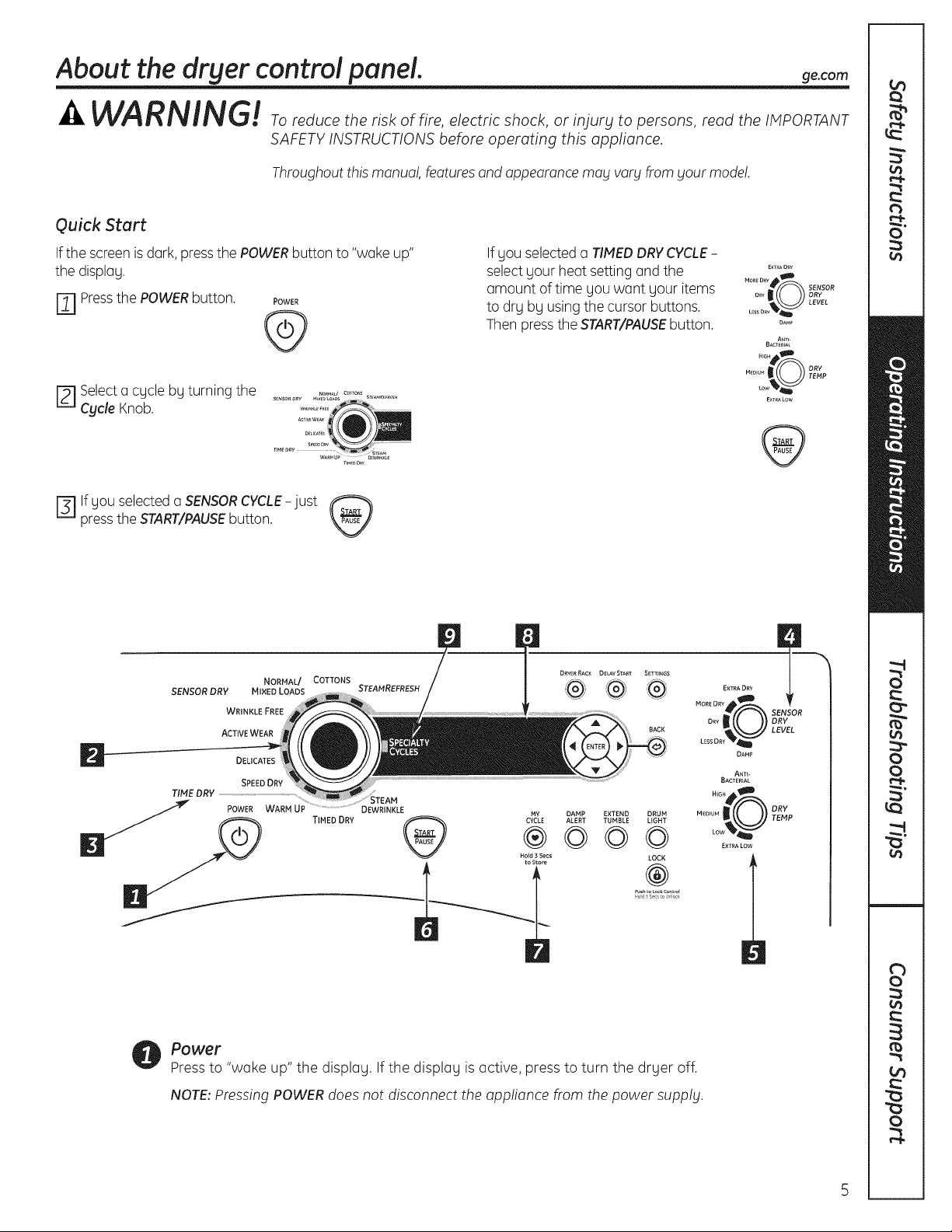
About the dryer control panel, ge.com
SAFETY INSTRUCTIONS before operating this appliance.
Throughout this monuo!,featuresand appearancemog vorg from gout mode!.
Quick Start
Ifthe screen isdark,pressthe POWERbutton to "woke up"
the display.
r_l Pressthe POWERbutton. POWER
@
r_ Selecto cgcle by turning the
Cycle Knob.
press the START/PAUSE button.
Fiif gou selected o SENSOR CYCLE-just
SENSOR DRY MIXED LOADS STEAMREFRESH
TIME DRY ..........................................................................................
NORMAL/ COTTONS
WRINKLE FREE
ACTIVE WEAR
SPEED DRY
TIMED DRY CyMcYE
If gou selected o TIMEDDRYCYCLE-
selectgour heat setting and the
amount of time you wont your items
to drg bg usingthe cursor buttons.
Then pressthe START/PAUSEbutton.
DRYER RACK DELAY START SETTINGS
I
BACK
MORELEsIRDDRY(gR SENSORLEvELDRY
®
©©©
DAMP EXTEND DRUM
ALERT TUMBLE UGHT
LOCK
M..... _ _ TDERVp4p
®
od _s_c o Jock
EXTRA DRY
ANTI-
BACTERIAL
N_G_ _D
EXTRA LOW
DAMP
E×T_AO_Y
MORED_Y_
DAM_
ANT_-
BACTERIAL
....s_
M_ou__ _ DRY
E×TRALOW
TEMPow'_
Power
Pressto "woke up" the display. If the display is active, press to turn the dryer off.
NOTE:Pressing POWER does not disconnect the appliance from the power supply.
i
Page 6
About the dryer control panel.
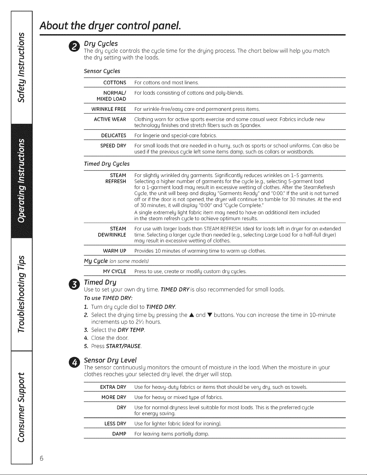
Dry Cycles
The dry cycle controls the cycle time for the drying process. The chart below will help you match
the dry setting with the loads.
Sensor Cycles
COTTONS For cottons and most linens.
NORMAL/ For loads consisting of cottons and poly-blends.
MIXED LOAD
WRINKLE FREE Forwrinkle-freeleasycare and permanent pressitems.
ACTIVE WEAR Clothingworn foractivesportsexerciseand some casual wear. Fabricsincludenew
technology finishesand stretchfiberssuch as Spandex.
DELICATES For lingerieand special-carefabrics.
SPEED DRY For small loads that are needed ina hurry,such as sportsor school uniforms.Can also be
used ifthe previouscycle leftsome items damp, such as collarsor waistbands.
Timed Dry Cycles
STEAM
REFRESH
STEAM For use with larger loads than STEAMREFRESH.Ideal for loads left in dryer for an extended
DEWRINKLE time. Selecting a larger cycle than needed (e.g.,selecting Large Load for a half-full dryer)
WARM UP Provides 10 minutes of warming time to warm up clothes.
My Cycle (on some models)
MY CYCLE Press to use, create or modify custom dry cycles,
For slightly wrinkled dry garments. Significantly reduces wrinkles on 1-5 garments.
Selecting a higher number of garments for the cycle (e.g.,selecting 5-garment load
for a 1-garment load) may result in excessive wetting of clothes. After the SteamRefresh
Cycle, the unit will beep and display "Garments Ready" and "0:00." If the unit is not turned
off or if the door is not opened, the dryer will continue to tumble for 30 minutes. At the end
of 30 minutes, it will display "0:00" and "Cycle Complete."
Asingle extremely light fabric item may need to have an additional item included
in the steam refresh cycle to achieve optimum results.
may result in excessive wetting of clothes.
Timed Dry
Use to set your own dry time. TIMED DRY is also recommended for small loads.
To use TIMED DRY:
1. Turn dry cycle dial to TIMED DRY.
2. Select the drying time by pressing the A and V buttons. You can increase the time in 10-minute
increments up to 2V2 hours.
3. Select the DRY TEMP.
4. Close the door.
5. Press START/PAUSE.
Sensor Dry Level
The sensor continuously monitors the amount of moisture in the load. When the moisture in your
clothes reaches your selected dry level, the dryer will stop.
EXTRADRY Use for heavy-duty fabrics or items that should be very dry, such as towels.
MORE DRY Use for heavy or mixed type of fabrics.
DRY Use for normal dryness level suitable for most loads. This is the preferred cycle
for energy saving.
LESSDRY Use for lighter fabric (ideal for ironing).
DAMP For leaving items partially damp.
6
Page 7
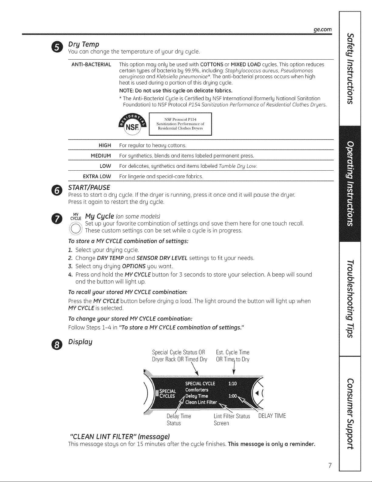
Dry Temp
You can change the
ge.com
temperature of your dry cycle.
ANTI-BACTERIAL
HIGH
MEDIUM
LOW
EXTRA LOW
START/PAUSE
Pressto start a dry cycle. If the dryer is running, press it once and it will pause the dryer.
Pressit again to restart the dry cycle.
MY My Cycle (on some models)
CYCLE
Set up your favorite combination of settings and save them here for one touch recall.
These custom settings can be set while a cycle is in progress.
This option may only be used with COTTONSor MIXED LOAD cycles. This option reduces
certain types of bacteria by 99.9%, including: Stophylococcus oureus, Pseudomonos
oeruginoso and Kle6siello pneumonioe*. The anti-bacterial process occurs when high
heat is used during a portion of this drying cycle.
NOTE:Do not use this cycle on delicate fabrics.
* The Anti-Bacterial Cycle is Certified by NSFInternational (formerly National Sanitation
Foundation) to NSFProtocol P154 Sonitizotion Performonce of Residentiol Clothes Dryers.
Sanitization Perfbrmance oi
Residential Clothes Dryers
For regular to heavy cottons.
For synthetics, blends and items labeled permanent press.
For delicates, synthetics and items labeled Tum61eDry Low.
For lingerie and special-care fabrics.
i
To store a NY CYCLEcombination of settings:
£ Select your drying cycle.
2. Change DRY TEPlPand SENSORDRYLEVELsettings to fit your needs.
3. Select any drying OPTIONSyou want.
4. Pressand hold the PlYCYCLEbutton for 3 seconds to store your selection. A beep will sound
and the button will light up.
To recall gour stored PIYCYCLEcombination:
Pressthe PlY CYCLEbutton before drying a load. The light around the button will light up when
PlYCYCLEis selected.
To change your stored PlY CYCLE combination:
Follow Steps 1-4 in "To store a PlY CYCLE combination of settings."
Display
SpecialCycleStatusOR
DryerRackORTimedDry
Est.CycleTime
ORTimlt0 Dry
4(
' Time Lint FilterStatus DELAYTIME
Status Screen
"CLEAN LiNT FILTER" (message)
This message stags on for 15 minutes after the cycle finishes. This message is only a reminder.
Page 8
About the dryer control panel.
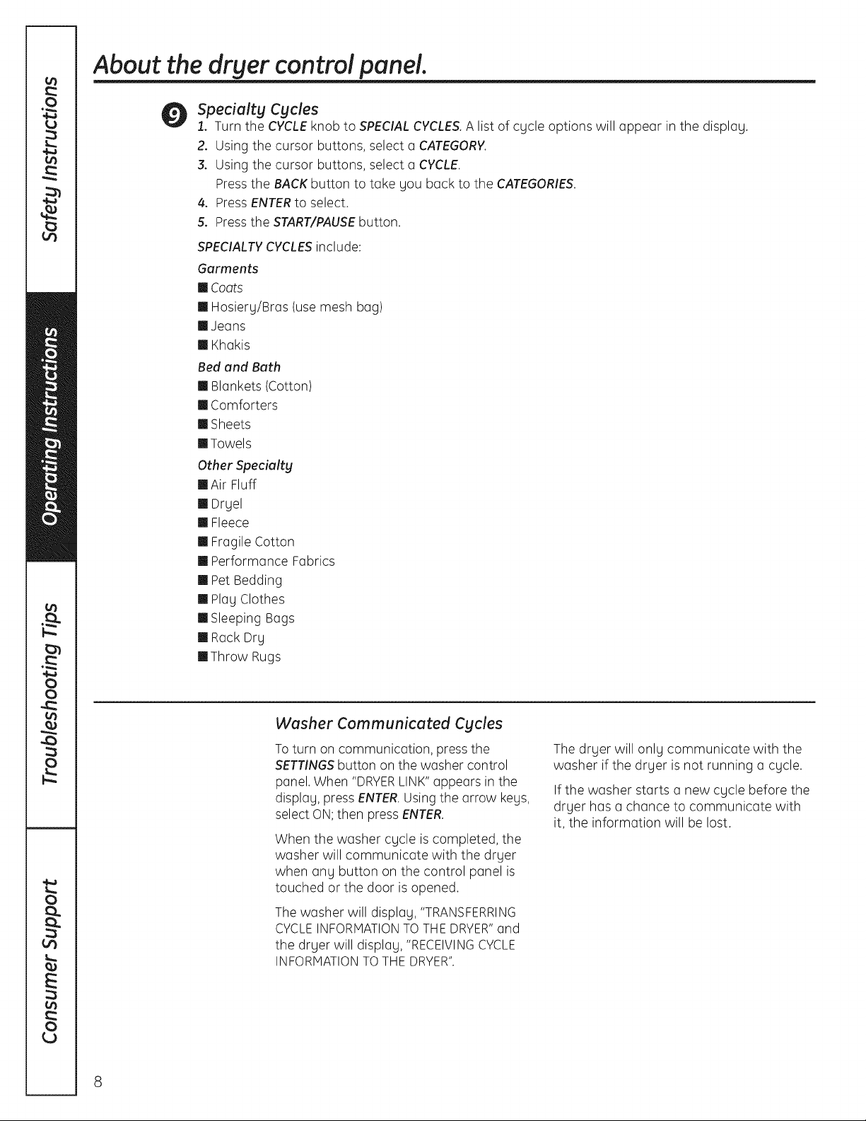
Specialty Cycles
1. Turn the CYCLE knob to SPECIAL CYCLES. Alist of cycle options will appear in the display.
2. Using the cursor buttons, select a CATEGORY.
3. Using the cursor buttons, select a CYCLE.
Press the BACK button to take you back to the CATEGORIES.
4. PressENTERto select.
5. Press the START/PAUSEbutton.
SPECIALTYCYCLESinclude:
Garments
Coots
m Hosierg/Bras (use mesh bag)
m Jeans
m Khakis
Bed end Beth
m Blankets (Cotton)
m Comforters
m Sheets
mTowels
Other Specialty
mAir Fluff
m Drgel
m Fleece
m Fragile Cotton
m Performance Fabrics
m Pet Bedding
m Play Clothes
m Sleeping Bags
m Rack Dry
mThrow Rugs
Washer Communicated Cycles
Toturn on communication, press the
SETTINGSbutton on the washer control
panel. When "DRYERLINK"appears in the
display, press ENTER.Usingthe arrow keys,
select ON;then press ENTER.
When the washer cycle is completed, the
washer will communicate with the dryer
when any button on the control panel is
touched or the door is opened.
The washer will display, "TRANSFERRING
CYCLEINFORMATIONTOTHE DRYER"and
the dryer will display, "RECEIVINGCYCLE
INFORMATIONTOTHEDRYER".
8
The dryer will only communicate with the
washer if the dryer is not running a cycle.
If the washer starts a new cycle before the
dryer has a chance to communicate with
it, the information will be lost.
Page 9
About cycle options.
NOTE: Not all features are available on all dryer models. ge.com
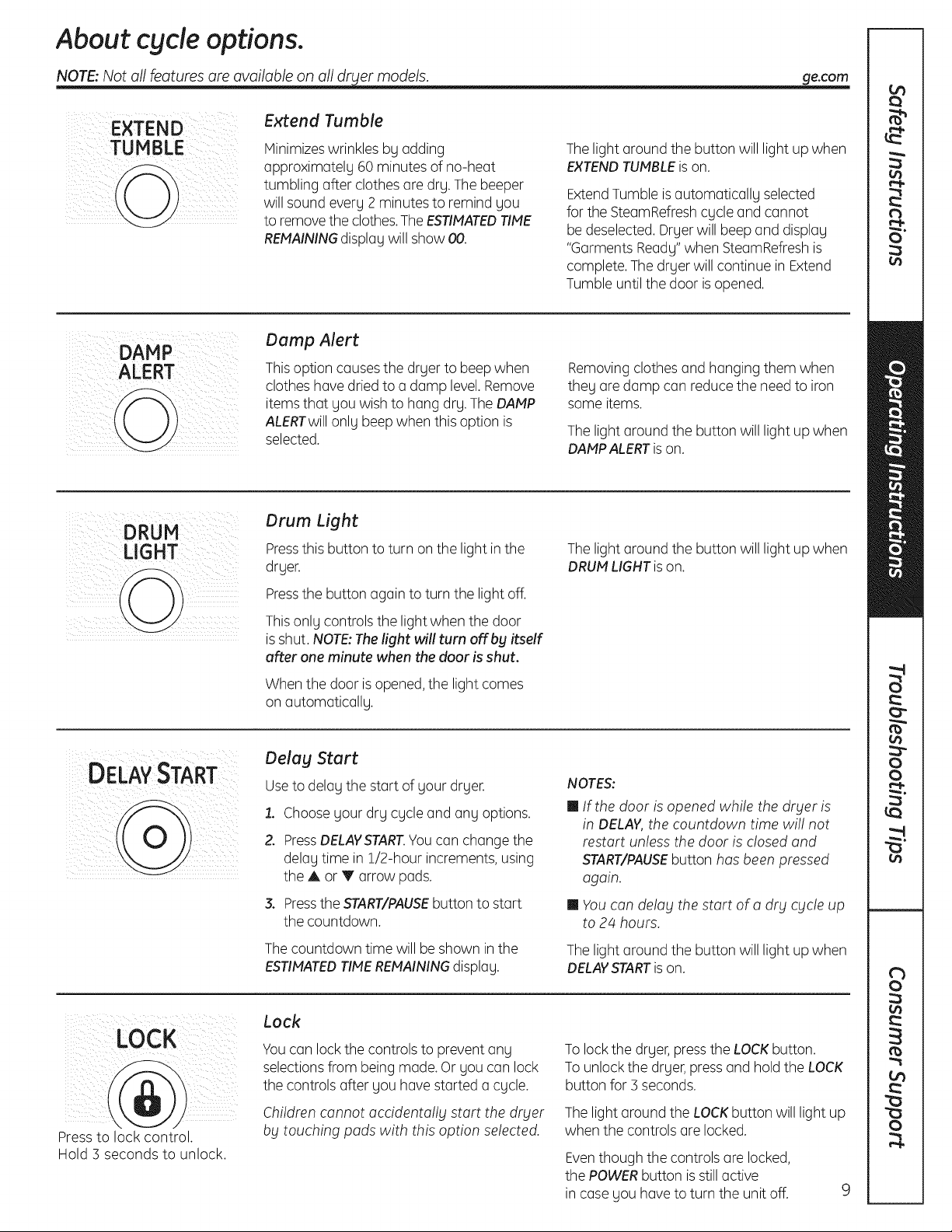
EXTEND
TU N BLE
ALERT
DRUM
LIGHT
Extend Tumble
Minimizeswrinkles by adding
approximately 60 minutes of no-heat
tumbling after clothes are dry. The beeper
will sound every 2 minutesto remind you
to removethe clothes.TheESTIMATEDTIME
REMAININGdisplay will show 00.
Damp Alert
Thisoption causesthe dryer to beep when
clothes havedried to a damp level. Remove
itemsthat you wish to hang dry.TheDAMP
ALERTwillonly beepwhen this option is
selected.
Drum Light
Pressthis button to turn on the light in the
dryer.
Pressthe button again to turn the light off.
Thelight around the button will light up when
EXTENDTUMBLEison.
ExtendTumble isautomatically selected
for the SteamRefreshcycle and cannot
be deselected. Dryer will beep and display
"Garments Ready" when SteamRefreshis
complete. Thedryer will continue in Extend
Tumble until the door isopened.
Removingclothes and hanging them when
they are damp can reducethe needto iron
some items.
The light around the button will light up when
DAMPALERTison.
The light around the button will light up when
DRUMLIGHTis on.
DELAY START
i(7!i!i ¸¸LL !/ ki ¸
ii ii:ii ii
i ii i iIi
Press to lock control.
Hold 3 seconds to unlock.
Thisonly controls the lightwhen the door
isshut. NOTE:Thelight will turn off bg itself
after one minute when the door is shut.
When the door is opened,the light comes
on automatically.
Delay Start
Useto delay the start of your dryer.
1. Choose your dry cycle and any options.
Z PressDELAYSTART.Youcan change the
delay time in 1/2-hour increments,using
the A or V arrow pads.
3. Pressthe START/PAUSEbutton to start
the countdown.
Thecountdown time will be shown inthe
ESTIMATEDTIMEREMAININGdisplay.
Lock
Youcan lock the controls to prevent any
selectionsfrom being made. Or you can lock
the controls after you have started a cycle.
Children cannot accidentally start the dryer
by touching pads with this option selected.
NOTES:
m If the door is opened while the dryer is
in DELAY,the countdown time wi!! not
restart unless the door is closed and
START/PAUSEbutton has beenpressed
again.
m Youcan delay the start of a dry cycle up
to 24 hours.
Thelight around the button will light up when
DELAYSTARTison.
Tolock the dryer, pressthe LOCKbutton.
Tounlock the dryer,press and holdthe LOCK
button for 5 seconds.
Thelight around the LOCKbutton will light up
when the controls are locked.
Eventhough the controls are locked,
the POWERbutton is still active
in case you have to turn the unit off.
9
Page 10
About cycle options.
NOTE:Notallfeaturesare availableonalldryer models.
Settings
SETTINGS
kku2,'
Under the SETTINGSoption, you can
adjust the volume or the brightness of
the displag.
VOLUME
m End of Cgcle (signal) volume can be set
from HIGH, PIED,LOW or OFF.
m Control Sounds volume can be set from
HIGH, PIED,LOW or OFF.
About dryer features.
Drum Lamp
Before replacing the light bulb, be sure to unplug the drger power cord or
disconnect the dryer at the household distribution panel bg removing the
fuse or switching off the circuit breaker. Reach above dryer opening from
inside the drum. Remove the bulb and replace with the same size bulb.
DISPLAYBRIGHTNESScan be set from
HIGH, PIED or LOW.
After gou have made gour selection,
press ENTER.
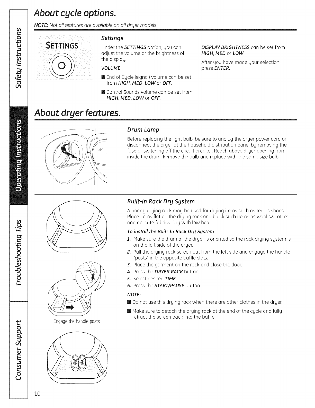
Engagethe handleposts
Built-In Rack Dry System
A handg drging rack mag be used for drging items such as tennis shoes.
Place items flat on the drying rack and block such items as wool sweaters
and delicate fabrics. Drg with low heat.
To install the Built-In Rack Dry Sgstem
1. Make sure the drum of the drger is oriented so the rack drging sgstem is
on the left side of the drger.
2. Pull the drging rack screen out from the left side and engage the handle
"posts" in the opposite baffle slots.
3. Place the garment on the rack and close the door.
4. Press the DRYERRACKbutton.
5. Select desired TIPIE.
6. Press the START/PAUSEbutton.
NOTE:
m Do not use this drging rack when there are other clothes in the drger.
m Make sure to detach the drging rack at the end of the cgcle and fullg
retract the screen back into the baffle.
10
Page 11
ge.com
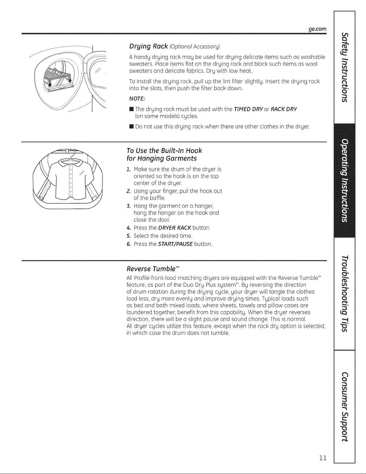
Drying Rock IOptional Accessory)
A handy drying rack may be used for drying delicate items such as washable
sweaters. Place items flat on the drying rack and block such items as wool
sweaters and delicate fabrics. Dry with low heat.
To install the drying rack, pull up the lint filter slightly. Insert the drying rack
into the slots, then push the filter back down.
NOTE:
m The drying rack must be used with the TIMED DRYor RACKDRY
(on some models) cycles.
m Donot use this drying rack when there are other clothes in the dryer.
To Use the Built-In Hook
for Hanging Gorments
1. Make sure the drum of the dryer is
oriented so the hook is on the top
center of the dryer.
2. Using your finger, pull the hook out
of the baffle.
3. Hang the garment on a hanger,
hang the hanger on the hook and
close the door.
4. Pressthe DRYERRACKbutton.
5. Select the desired time.
6. Pressthe START/PAUSEbutton.
Reverse Tumble'"
All Profile front-load matching dryers are equipped with the ReverseTumbleT"
feature, as part of the Duo Dry Plus system _'.By reversing the direction
of drum rotation during the drying cycle, your dryer will tangle the clothes
load less, dry more evenly and improve drying times. Typical loads such
as bed and bath mixed loads, where sheets, towels and pillow cases are
laundered together, benefit from this capability. When the dryer reverses
direction, there will be a slight pause and sound change. This is normal.
All dryer cycles utilize this feature, except when the rack dry option is selected,
in which case the drum does not tumble.
11
Page 12
Using the dryer.
Always follow fabric manufacturer's care label when laundering.
Sorting and Loading Hints
Asa general rule, ifclothes are sorted
properly for the washer,they are sorted
properly for the dryer.Try also to sort items
according to size.Forexample, do not dry
a sheet with socksor other small items.
Do not add fabric softener sheetsonce
the load has become warm. They may
cause fabric softener stains. Bounce®
Fabric Conditioner Dryer Sheets have
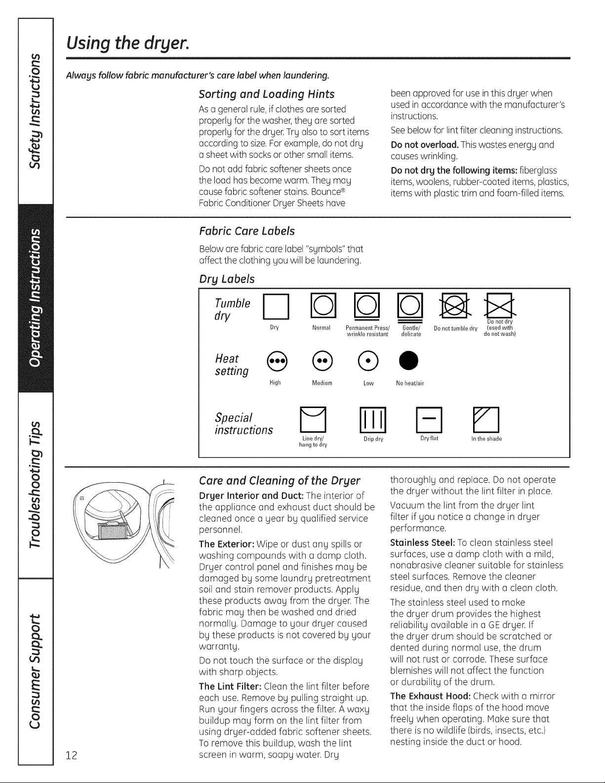
Fabric Care Labels
Beloware fabric care label "symbols" that
affect the clothing you will be laundering.
Dry Labels
dry
N rb-lrOq
Dry Normal Permanent Press/
wrinkle resistant
setting
High Medium Low
been approved for use inthis dryer when
used in accordance with the manufacturer's
instructions.
Seebelow for lintfilter cleaning instructions.
Do not overload. This wastes energy and
causeswrinkling.
Do not drg the following items: fiberglass
items,woolens, rubber-coated items, plastics,
items with plastic trim andfoam-filled items.
Gentle/ Denet tumble dry (used with
delicate do not wash)
Do not dry
0
No heat/air
12
instructions
I=1 Iml
Line dry/ Drip dry
hang to dry
Care and Cleaning of the Dryer
Drger Interior and Duct: The interior of
the appliance and exhaust duct should be
cleaned once a gear by qualified service
personnel.
The Exterior: Wipe or dust any spills or
washing compounds with a damp cloth.
Dryer control panel and finishes may be
damaged by some laundry pretreatment
soil and stain remover products. Apply
these products away from the dryer. The
fabric may then be washed and dried
normally. Damage to your dryer caused
by these products is not covered by your
warranty.
Do not touch the surface or the display
with sharp objects.
The Lint Filter: Clean the lint filter before
each use. Remove by pulling straight up.
Run your fingers across the filter. A waxy
buildup may form on the lint filter from
using dryer-added fabric softener sheets.
To remove this buildup, wash the lint
screen in warm, soapy water. Dry
Fq
Dry flat
thoroughly and replace. Do not operate
the dryer without the lint filter in place.
Vacuum the lint from the dryer lint
filter if you notice a change in dryer
performance.
Stainless Steel: To clean stainless steel
surfaces, use a damp cloth with a mild,
nonabrasive cleaner suitable for stainless
steel surfaces. Remove the cleaner
residue, and then dry with a clean cloth.
The stainless steel used to make
the dryer drum provides the highest
reliability available in a GEdryer. If
the dryer drum should be scratched or
dented during normal use, the drum
will not rust or corrode. These surface
blemishes will not affect the function
or durability of the drum.
The Exhaust Hood: Check with a mirror
that the inside flaps of the hood move
freely when operating. Hake sure that
there isno wildlife (birds, insects, etc.)
nesting inside the duct or hood.
In the shade
Page 13
I stallti
structi
I
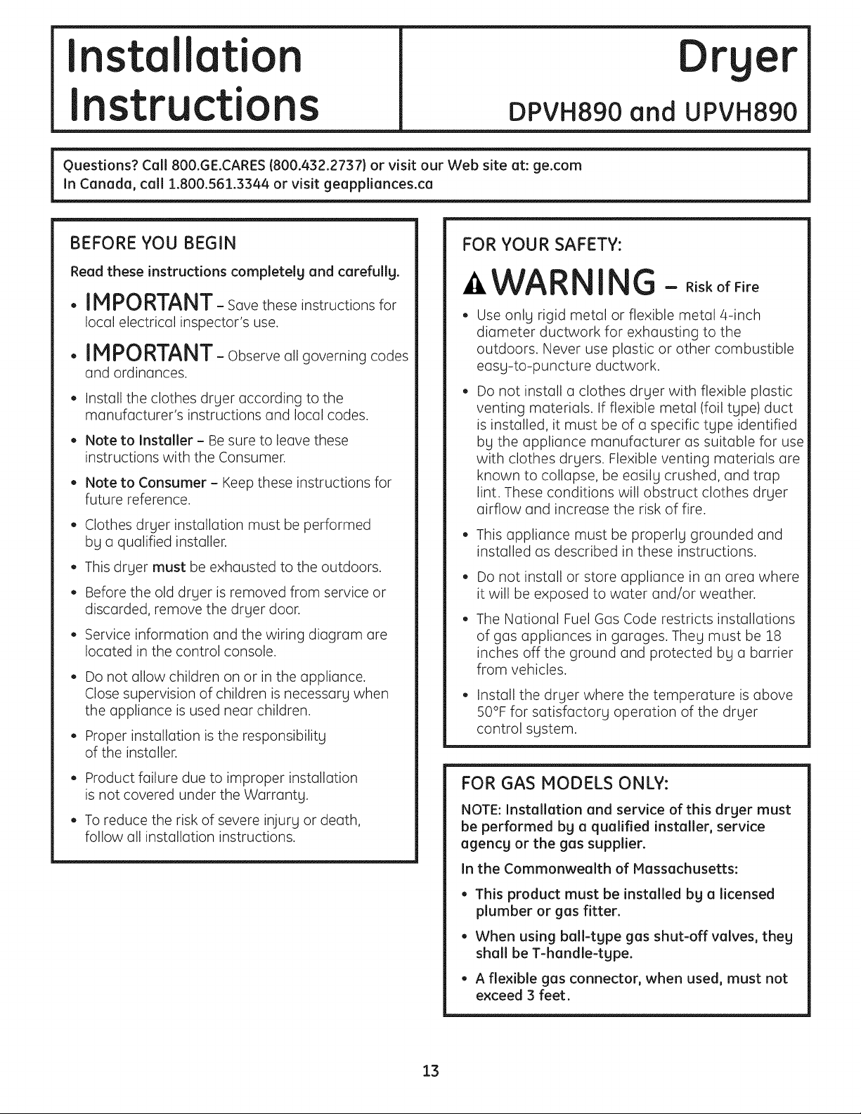
Questions? Call800.GE.CARES (800.432.2737)or visitour Web siteat:ge.com
InCanada, coll1.800.561.3344or visitgeappliances.ca i
DPVH890 and UPVH890
Dryer
BEFORE YOU BEGIN
Read these instructionscompletelyand carefully.
•IMPORTANT- savetheseinstructionsfor
local electrical inspector's use.
• IMPORTANT-Observeallgoverningcodes
and ordinances.
• Install the clothes dryer according to the
manufacturer's instructions and local codes.
• Note to Installer - Be sure to leave these
instructions with the Consumer.
• Note to Consumer - Keep these instructions for
future reference.
• Clothes dryer installation must be performed
by a qualified installer.
• This dryer must be exhausted to the outdoors.
• Before the old dryer is removed from service or
discarded, remove the dryer door.
• Service information and the wiring diagram are
located in the control console.
• Do not allow children on or in the appliance.
Close supervision of children is necessary when
the appliance is used near children.
• Proper installation is the responsibility
of the installer.
FOR YOUR SAFETY:
_WARNI G - RiskofFire
Use only rigid metal or flexible metal 4-inch
diameter ductwork for exhausting to the
outdoors. Never use plastic or other combustible
easy-to-puncture ductwork.
Do not install a clothes dryer with flexible plastic
venting materials. If flexible metal (foil type) duct
is installed, it must be of a specific type identified
by the appliance manufacturer as suitable for use
with clothes dryers. Flexible venting materials are
known to collapse, be easily crushed, and trap
lint. These conditions will obstruct clothes dryer
airflow and increase the risk of fire.
• This appliance must be properly grounded and
installed as described in these instructions.
Do not install or store appliance in on area where
it will be exposed to water and/or weather.
The National Fuel Gas Code restricts installations
of gas appliances in garages. They must be 18
inches off the ground and protected by a barrier
from vehicles.
• Install the dryer where the temperature is above
50°F for satisfactory operation of the dryer
control system.
• Product failure due to improper installation
is not covered under the Warranty.
• To reduce the risk of severe injury or death,
follow all installation instructions.
FOR GAS MODELS ONLY:
NOTE: Installation and service of this dryer must
be performed bg a qualified installer, service
agency or the gas supplier.
In the Commonwealth of Massachusetts:
• This product must be installed bg a licensed
plumber or gas fitter.
• When using ball-type gas shut-off valves, they
shall be T-handle-type.
• A flexible gas connector, when used, must not
exceed 3 feet.
13
Page 14
Installation Instructions
UNPACKING YOUR DRYER
Tilt the dryer sideways and remove the foam
shipping pads by pulling at the sides and breaking
them away from the dryer legs. Be sure to remove
all of the foam pieces around the legs.
Remove the bag containing the literature and serial
cable.
LOCATION OF YOUR DRYER
MINIMUM CLEARANCE OTHER THAN
ALCOVE OR CLOSET INSTALLATION
Minimum clearance to combustible surfaces and
for air openings are:
• 0 inch clearance both sides
• 1 inch front
• 3 inches rear
Consideration must be given to provide adequate
clearance for proper operation and service.
DRYER DIMENSIONS
FrontView
-il i
(68.6cm)
53"
(134.6cm)
oOo o: o
27"
oooo o
T
39.5"
(100.3 cm)
14
Side View
m m
33.5"
(85.1 cm)
39.5"
(100.3cm)
Page 15
Installation Instructions
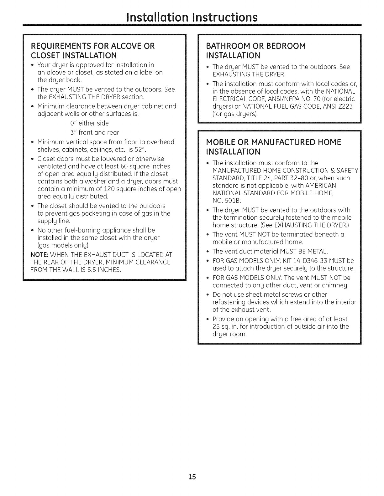
REQUIREMENTS FOR ALCOVE OR
CLOSET INSTALLATION
• Your dryer is approved for installation in
an alcove or closet, as stated on a label on
the dryer back.
• The dryer MUST be vented to the outdoors. See
the EXHAUSTING THE DRYERsection.
• Minimum clearance between dryer cabinet and
adjacent walls or other surfaces is:
0" either side
3" front and rear
• Minimum vertical space from floor to overhead
shelves, cabinets, ceilings, etc., is 52".
• Closet doors must be Iouvered or otherwise
ventilated and have at least 60 square inches
of open area equally distributed. If the closet
contains both a washer and a dryer, doors must
contain a minimum of 120 square inches of open
area equally distributed.
• The closet should be vented to the outdoors
to prevent gas pocketing in case of gas in the
supply line.
• No other fuel-burning appliance shall be
installed in the same closet with the dryer
(gas models only).
NOTE: WHEN THE EXHAUST DUCT IS LOCATEDAT
THE REAROF THE DRYER, MINIMUM CLEARANCE
FROM THE WALL IS 5.5 INCHES.
BATHROOM OR BEDROOM
INSTALLATION
• The dryer MUST be vented to the outdoors. See
EXHAUSTING THE DRYER.
• The installation must conform with local codes or,
in the absence of local codes, with the NATIONAL
ELECTRICALCODE, ANSI/NFPA NO. 70 (for electric
dryers) or NATIONAL FUEL GAS CODE, ANSI Z223
(for gas dryers).
MOBILE OR MANUFACTURED HOME
INSTALLATION
• The installation must conform to the
MANUFACTURED HOME CONSTRUCTION & SAFETY
STANDARD, TITLE 24, PART32-80 or, when such
standard is not applicable, with AMERICAN
NATIONAL STANDARD FOR MOBILE HOME,
NO. 501B.
• The dryer MUST be vented to the outdoors with
the termination securely fastened to the mobile
home structure. (See EXHAUSTING THE DRYER.)
• The vent MUST NOT be terminated beneath a
mobile or manufactured home.
• The vent duct material MUST BE METAL.
• FOR GAS MODELS ONLY: KIT 14-D346-33 MUST be
used to attach the dryer securely to the structure.
• FOR GAS MODELS ONLY: The vent MUST NOT be
connected to any other duct, vent or chimney.
• Do not use sheet metal screws or other
refastening devices which extend into the interior
of the exhaust vent.
• Provide an opening with a free area of at least
25 sq. in. for introduction of outside air into the
dryer room.
15
Page 16

Installation Instructions
CONNECTING INLET HOSES
CONNECTING INLET HOSES
To produce steam, the dryer must connect to
the cold water supply. Since the washer must
also connect to the cold water, a "`7"connector
is inserted to allow both inlet hoses to make that
connection at the same time.
NOTE: Use the new inlet hoses provided; never
use old hoses.
, Turn the cold water faucet off. Remove the
washer inlet hose from the washer fill valve
connector (cold).
2. Ensure the rubber flat washer is in place and
screw the female coupling of the short hose
onto the washer fill valve connector. Tighten
by hand until firmly seated.
3. Attach the female end of the '"7" connector
to the male coupling of the short hose. Ensure
the rubber flat washer is in place. Tighten
by hand until firmly seated.
CONNECTING INLET HOSES (cont.}
7. Using pliers, tighten all the couplings with
an additional two-thirds turn.
NOTE: Do not overtighten. Damage to the couplings
may result.
8. Turn the water faucet on.
9. Check for leaks around the "`7" connector,
faucet and hose couplings.
4. Insert the filter screen in the coupling of the
washer's inlet hose. If a rubber flat washer
is already in place remove it before installing
the filter screen. Attach this coupling to one male
end of the "`7" connector. Tighten by hand until
firmly seated.
5. Ensure the rubber flat washer is in place and
attach the dryer's long inlet hose to the other
male end of the "'7" connector. Tighten by hand
until firmly seated.
,
Ensure the rubber flat washer is in place and
attach the other end of the dryer's long inlet
hose to the fill valve connector at the bottom
of the dryer back panel. Tighten by hand until
firmly seated.
WATER SUPPLY REQUIREMENTS
Hot and cold water faucets MUST be installed
within 42 in. (107 cm) of your washer's water inlet.
The faucets MUST be 3/4 in. (1.9 cm) garden
hose-type so inlet hoses can be connected. Water
pressure MUST be between 10 and 120 pounds
per square inch. Your water department can
advise you of your water pressure.
NOTE: A water softener is recommended to reduce
buildup of scale inside the steam generator
if the home water supply is very hard.
16
Page 17
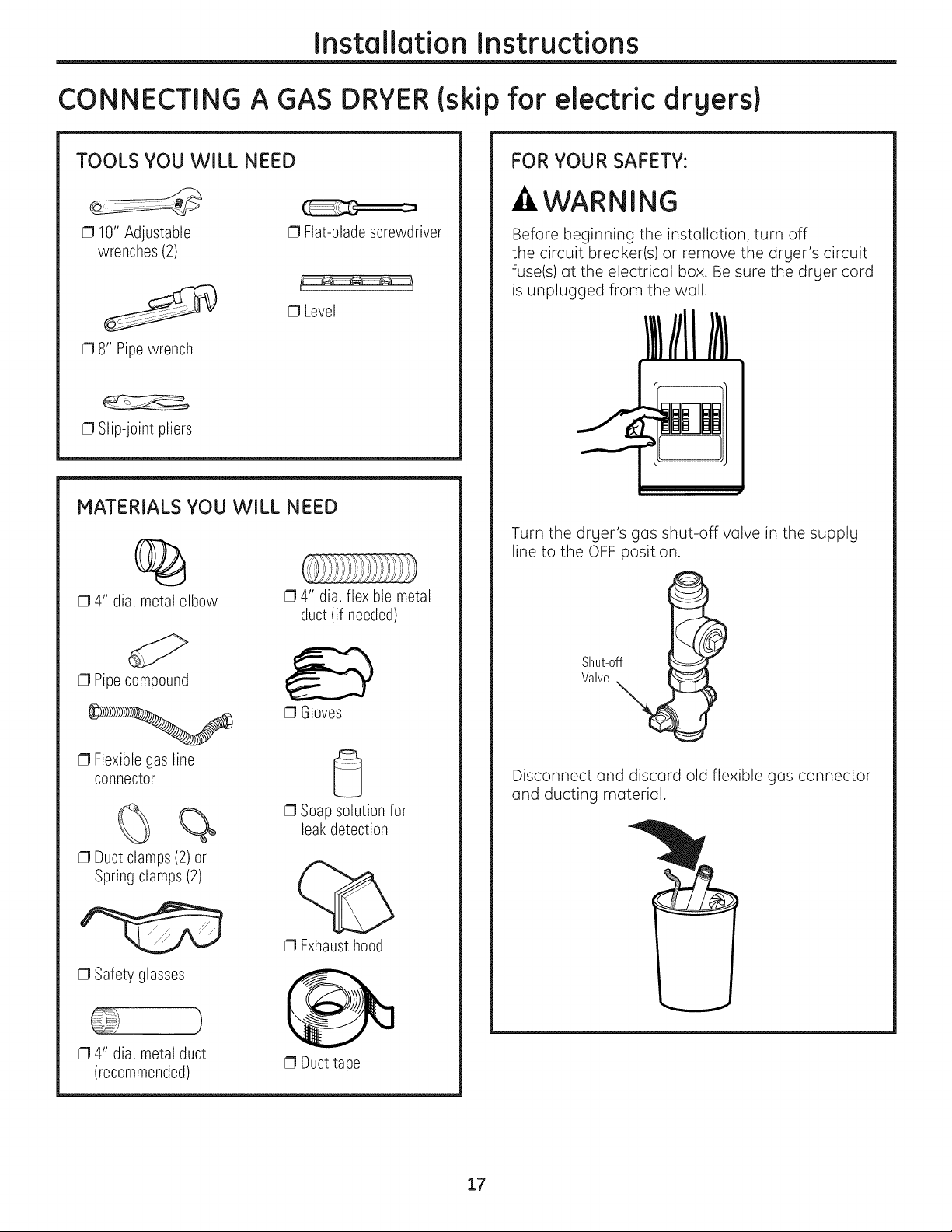
Installation Instructions
CONNECTING A GAS DRYER(skip for electric drgers}
TOOLS YOU WILL NEED
[] 10" Adjustable
wrenches (2)
[] 8" Pipewrench
[] Slip-joint pliers
[] Flat-blade screwdriver
[] Level
MATERIALS YOU WILL NEED
%
[] 4" dia. metal elbow
[] 4" dia. flexible metal
duct (if needed)
FOR YOUR SAFETY:
-&WARNING
Before beginning the installation, turn off
the circuit breaker(s) or remove the drger's circuit
fuse(s) at the electrical box. Be sure the drger cord
is unplugged from the wall.
Turn the drger's gas shut-off valve in the supplg
line to the OFF position.
[] Pipecompound
[] Flexible gas line
connector
%
[] Duct clamps (2) or
Spring clamps (2)
[] Safety glasses
[] 4" dia. metal duct
(recommended)
Shut-off
Valve
[] Gloves
Disconnect and discard old flexible gas connector
and ducting material.
[] Soap solution for
leakdetection
[] Exhaust hood
[] Duct tape
17
Page 18
Installation Instructions
CONNECTING A GAS DRYER (cont.)
GAS REQUIREMENTS
WARNING
Installation must conform to local codes
and ordinances, or in their absence, the
NATIONAL FUEL GAS CODE, ANSI Z223.
• This gas dryer is equipped with a Valve and
Burner Assembly for use only with natural gas.
Using conversion kit 14-A048, your local service
organization can convert this dryer for use with
propane (LP)gas. ALL CONVERSIONS MUST BE
MADE BY PROPERLYTRAINED AND C.)UALIFIED
PERSONNEL AND IN ACCORDANCE WITH LOCAL
CODES AND ORDINANCE REQUIREMENTS.
• The dryer must be disconnected from the gas
supply piping system during any pressure testing
of that system at a test pressure in excess of
0.5 PSI(3.4 KPa).
The dryer must be isolated from the gas supply
piping system by closing the equipment shut-off
valve during any pressure testing of the gas
supply piping of test pressure equal to or less
than 0.5 PSI(3.4KPa).
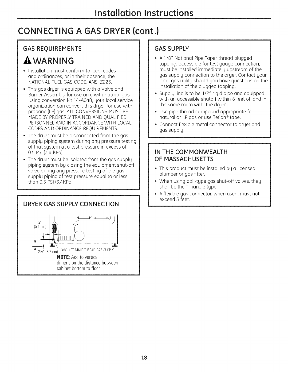
DRYER GAS SUPPLY CONNECTION
GAS SUPPLY
• A 1/8" National Pipe Taper thread plugged
tapping, accessible for test gauge connection,
must be installed immediately upstream of the
gas supply connection to the dryer. Contact your
local gas utility should you have questions on the
installation of the plugged tapping.
• Supply line is to be 1/2" rigid pipe and equipped
with an accessible shutoff within 6 feet of, and in
the same room with, the dryer.
• Use pipe thread compound appropriate for
natural or LP gas or use Teflon ®tape.
• Connect flexible metal connector to dryer and
gas supply.
IN THE COMMONWEALTH
OF MASSACHUSETTS
• This product must be installed by a licensed
plumber or gas fitter.
• When using ball-type gas shut-off valves, they
shall be the T-handle type.
• A flexible gas connector, when used, must not
exceed 3 feet.
12%" (6.7 om_308T"F?PAddlEoT;2;t_2_AS SUPPLY
dimensionthedistancebetween
cabinet bottom to floor.
18
Page 19
Installation Instructions
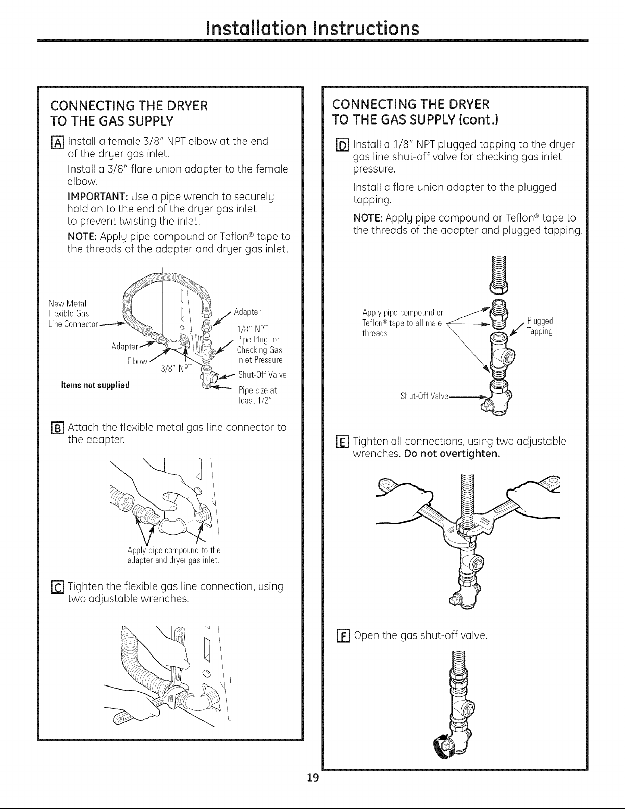
CONNECTING THE DRYER
TO THE GAS SUPPLY
r_ Install a female 3/8" NPT elbow at the end
of the dryer gas inlet.
Install a 3/8" flare union adapter to the female
elbow.
IMPORTANT: Use a pipe wrench to securely
hold on to the end of the dryer gas inlet
to prevent twisting the inlet.
NOTE: Apply pipe compound or Teflon ®tape to
the threads of the adapter and dryer gas inlet.
NewMetal __
FlexibleGas ,j Adapter
Line Connector.----__, _ __ 1/8" NPT
__., PipePlugfor
Adapter_ >_ _/IC_J CheckingGas
Elbowj ...... [_,.J Inlet Pressure
Ss'NPT Shut-OffValve
Items not supplied _-_"" Pipesize at
least1/2"
CONNECTING THE DRYER
TO THE GAS SUPPLY {cont.}
@Install a 1/8" NPT plugged tapping to the dryer
gas line shut-off valve for checking gas inlet
pressure.
Install a flare union adapter to the plugged
tapping.
NOTE: Apply pipe compound or Teflon ® tape to
the threads of the adapter and plugged tapping.
Applypipecompoundor __
Teflon®tapeto all male X_--------b_'_ / Plugged
threads. _ _t¢" Tapping
Shut-OffValve__ !
[] Attach the flexible metal gas line connector to
the adapter.
Apply pipe compound to the
adapter and dryer gas inlet.
[-C']Tighten the flexible gas line connection, using
two adjustable wrenches.
E] Tighten all connections, using two adjustable
wrenches. Do not overtighten.
r_ open the gas shut-off valve.
19
Page 20
Installation Instructions
CONNECTING A GAS DRYER (cont.)
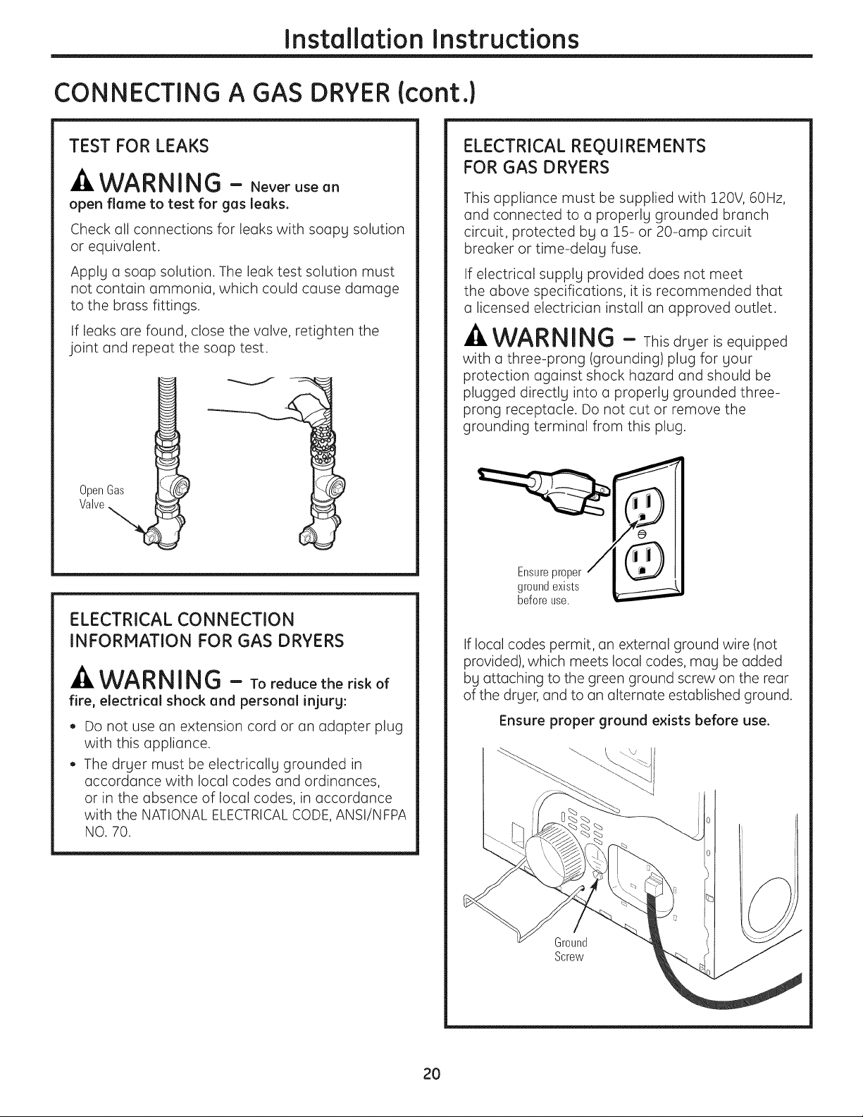
TEST FOR LEAKS
_k WARNING - Neverusean
open flame to test for gas leaks.
Check all connections for leaks with soapy solution
or equivalent.
Apply a soap solution. The leak test solution must
not contain ammonia, which could cause damage
to the brass fittings.
If leaks are found, close the valve, retighten the
joint and repeat the soap test.
OpenGas
Valve
ELECTRICAL REQUIREMENTS
FOR GAS DRYERS
This appliance must be supplied with 120V, 60Hz,
and connected to a properly grounded branch
circuit, protected by a 15- or 20-amp circuit
breaker or time-delay fuse.
If electrical supply provided does not meet
the above specifications, it is recommended that
a licensed electrician install an approved outlet.
-_WARNING - Thisdryer is equipped
witha three-prong(grounding)plugforyour
protectionagainstshock hazard and shouldbe
plugged directlyintoa properlygrounded three-
prong receptacle.Do not cutor remove the
groundingterminalfrom thisplug.
ELECTRICAL CONNECTION
INFORMATION FOR GAS DRYERS
WARNING - Toreducetheriskof
fire, electrical shock and personal injurg:
Do not use an extension cord or an adapter plug
with this appliance.
The dryer must be electrically grounded in
accordance with local codes and ordinances,
or in the absence of local codes, in accordance
with the NATIONAL ELECTRICALCODE, ANSI/NFPA
NO. 70.
Ensure proper
ground exists
before use.
If local codes permit, an external ground wire (not
provided), which meets local codes, may be added
by attaching to the green ground screw on the rear
of the dryer, and to an alternate established ground.
Ensure proper ground exists before use.
Ground
Screw
20
Page 21
Installation Instructions
CONNECTING AN ELECTRICDRYER(skip for gas dryers}
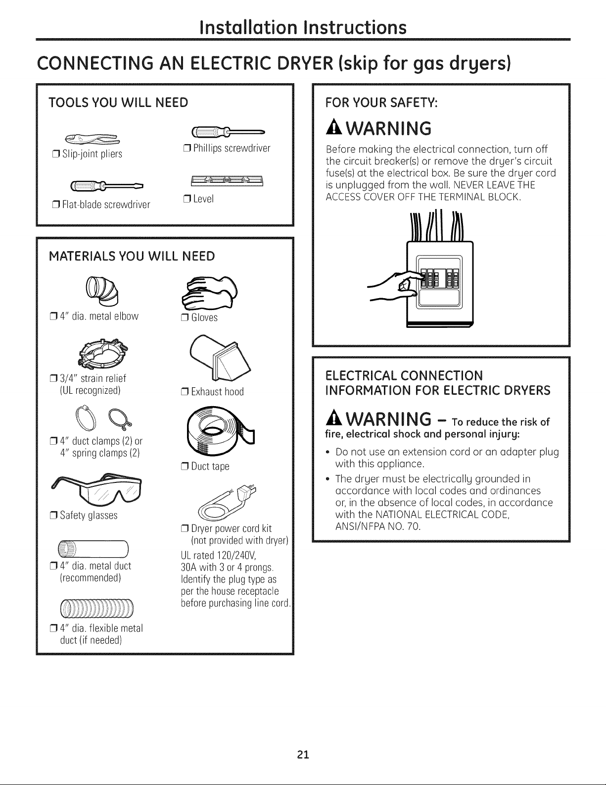
TOOLS YOU WILL NEED
[] Slip-joint pliers
[] Flat-blade screwdriver
MATERIALS YOU WILL NEED
[] Phillips screwdriver
[] Level
%
[] 4" dia. metal elbow
[] Gloves
0
[] 3/4" strain relief
(ULrecognized)
[] Exhaust hood
FOR YOUR SAFETY:
-&WARNING
Before making the electrical connection, turn off
the circuit breaker(s) or remove the dryer's circuit
fuse(s) at the electrical box. Be sure the dryer cord
is unplugged from the wall. NEVER LEAVETHE
ACCESSCOVER OFF THE TERMINAL BLOCK.
ELECTRICAL CONNECTION
INFORMATION FOR ELECTRIC DRYERS
[] 4" duct clamps (2) or
4" spring clamps (2)
[] Safety glasses
[] 4" dia. metal duct
(recommended)
[] 4" dia. flexible metal
duct (if needed)
[] Duct tape
[] Dryer power cord kit
(not provided with dryer)
ULrated 120/240V,
30A with 3 or 4prongs.
Identify the plug type as
per the housereceptacle
before purchasing line cord.
-A WARNING - Toreducetheriskof
fire, electrical shock and personal injury:
• Do not use an extension cord or an adapter plug
with this appliance.
• The drger must be electricallg grounded in
accordance with local codes and ordinances
or, in the absence of local codes, in accordance
with the NATIONAL ELECTRICALCODE,
ANSI/NFPA NO. 70.
21
Page 22
Installation Instructions
CONNECTING AN ELECTRIC DRYER {cont.)
ELECTRICAL REQUIREMENTS
FOR ELECTRIC DRYERS
This dryer must be connected to an individual
brunch circuit, protected by the required time-
delay fuses or circuit breakers. A three- or four-
wire, single-phase, 120/240V, 60Hz, 30-amp
circuit is required.
If the electric supply does not meet the above
specifications, then call a licensed electrician.
GROUNDING INSTRUCTIONS
This dryer must be connected to a grounded metal,
permanent wiring system, or an equipment-
grounding conductor must be run with the circuit
conductors and connected to the equipment
grounding terminal on the appliance.
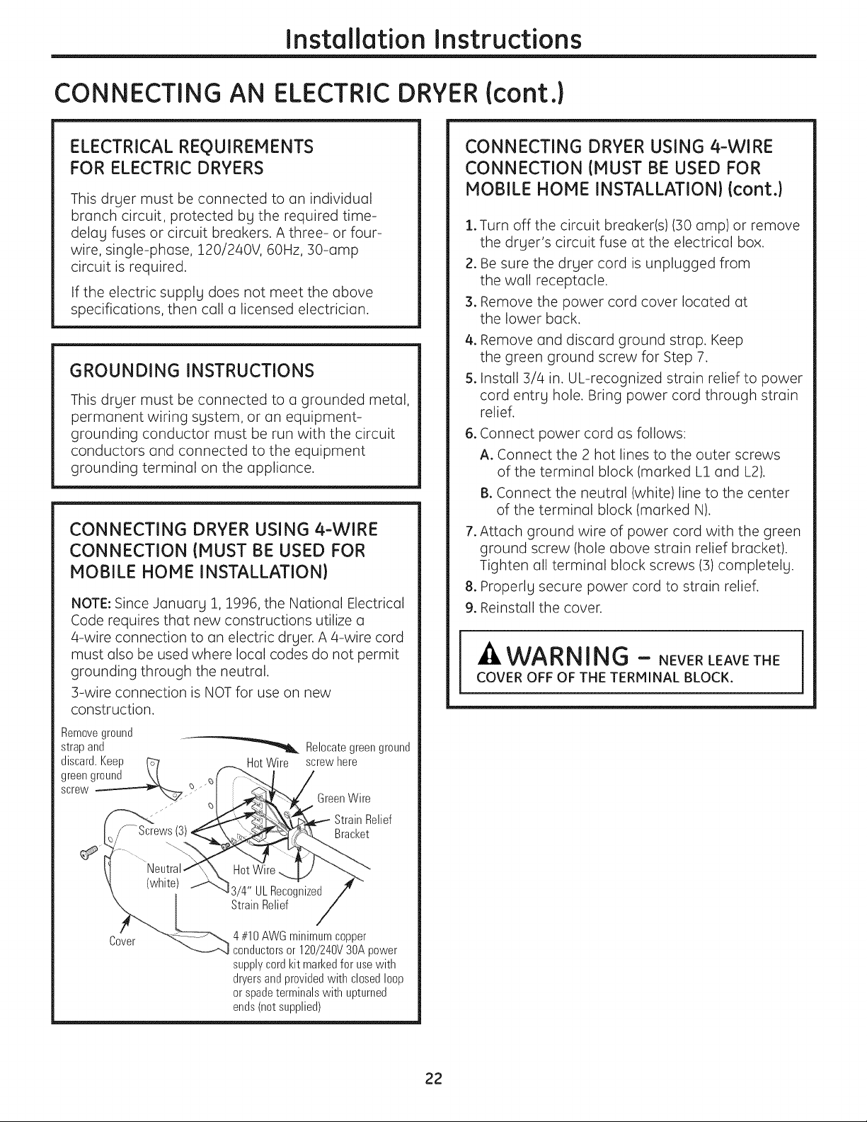
CONNECTING DRYER USING 4-WIRE
CONNECTION {MUST BE USED FOR
MOBILE HOME INSTALLATION}
NOTE: Since January 1, 1996, the National Electrical
Code requires that new constructions utilize a
4-wire connection to an electric dryer. A 4-wire cord
must also be used where local codes do not permit
grounding through the neutral.
3-wire connection is NOT for use on new
construction.
Removeground
strap and _ Relocate green ground
discard.Keep _ HotWire screwhere
green ground \t _ff _'_, I /
screw
_ /,_p£__"_ Green Wire
'_'_< __i_.._ - Strain Relief
_/-Screws(3} __,,. Bracket
CONNECTING DRYER USING 4-WIRE
CONNECTION {MUST BE USED FOR
MOBILE HONE INSTALLATION} {cont.}
.
Turn off the circuit breaker(s) (30 amp) or remove
the dryer's circuit fuse at the electrical box.
2.
Be sure the dryer cord is unplugged from
the well receptacle.
3.
Remove the power cord cover located at
the lower beck.
4.
Remove end discord ground strap. Keep
the green ground screw for Step 7.
5.
Install 3/4 in. UL-recognized strain relief to power
cord entry hole. Bring power cord through strain
relief.
.
Connect power cord us follows:
A. Connect the 2 hot lines to the outer screws
of the terminal block (marked L1 and L2).
B. Connect the neutral (white)line to the center
of the terminal block (marked N).
.
Attach ground wire of power cord with the green
ground screw (hole above strain relief bracket).
Tighten oil terminal block screws (3) completely.
.
Properly secure power cord to strain relief.
9.
Reinstall the cover.
WARNING - NEVERLEAVET,E
COVER OFF OF THE TERMINAL BLOCK.
" "-<_ 4#10 AWGminimumcopper
Lcvsr _-_',,_ conductors or 120/240V 30A power
supplycordkit markedfor usewith
dryersandprovidedwith closedloop
or spade terminals with upturned
ends (not supplied)
22
Page 23
Installation Instructions
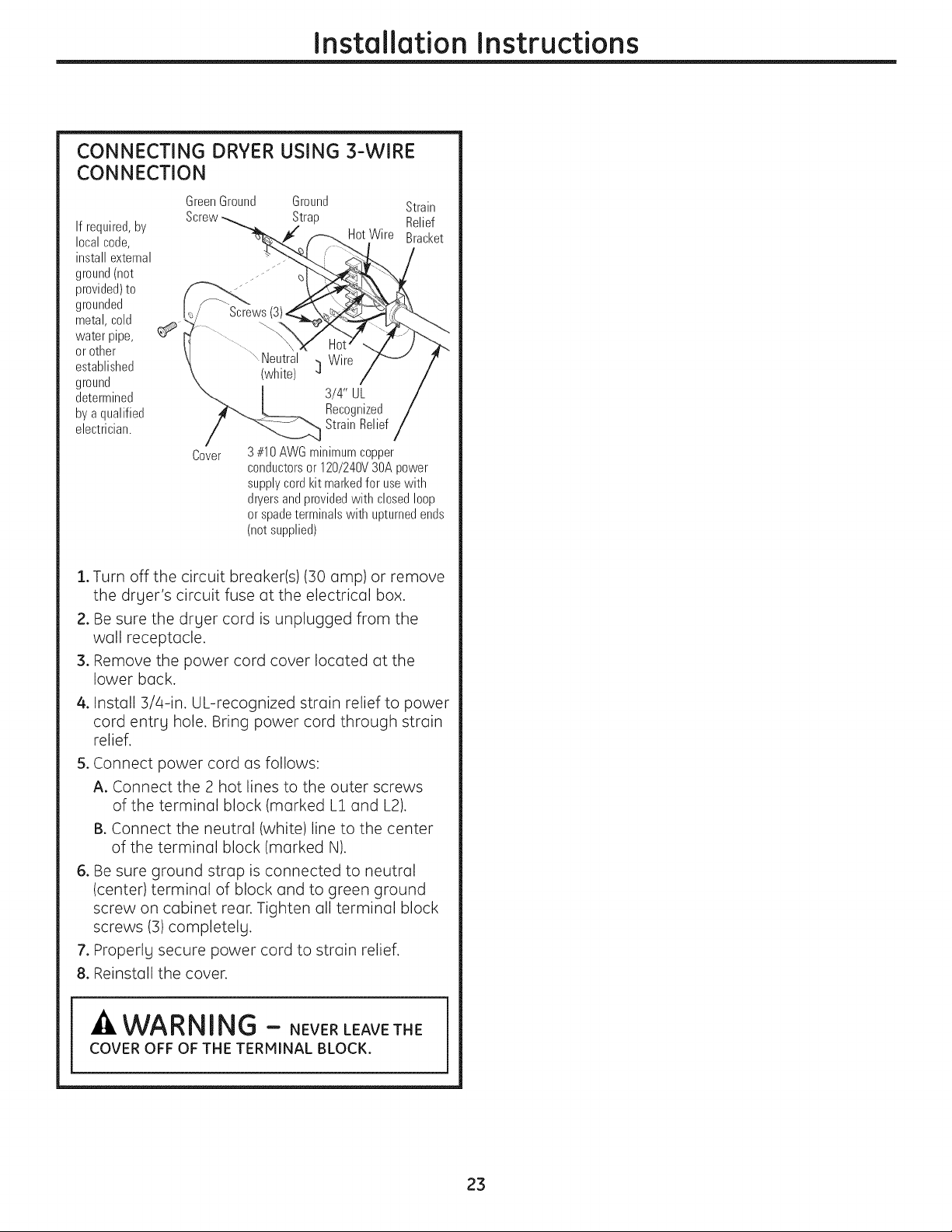
CONNECTING DRYER USING 3-WIRE
CONNECTION
GreenGround Ground Strain
Ifrequired,by
localcode,
installexternal
ground(not
provided)to
grounded
metal,cold
water pipe,
or other
established
ground
determined
bya qualified
electrician.
Screw Strap Relief
HotWire Bracket
Screws
Neutral Wire
(white) _]
3/4" UL
Recognized
StrainRelief
Cover
3#10AWGminimumcopper
conductorsor 120/240V30Apower
supplycordkit markedfor usewith
dryersandprovidedwith closedloop
or spadeterminalswith upturnedends
(notsupplied)
1.Turn off the circuit breaker(s) (30 amp) or remove
the dryer's circuit fuse at the electrical box.
2. Be sure the dryer cord is unplugged from the
well receptacle.
3. Remove the power cord cover located at the
lower beck.
4. Install 3/4-in. UL-recognized strain relief to power
cord entry hole. Bring power cord through strain
relief.
5. Connect power cord as follows:
A. Connect the 2 hot lines to the outer screws
of the terminal block (marked L1 and L2).
B. Connect the neutral (white)line to the center
of the terminal block (marked N).
6. Be sure ground strop is connected to neutral
(center) terminal of block and to green ground
screw on cabinet rear. Tighten oil terminal block
screws (3) completely.
7. Properly secure power cord to strain relief.
8. Reinstall the cover.
WARNING - NEVERLEAVETNE
COVER OFF OF THE TERMINAL BLOCK.
23
Page 24
Installation Instructions
EXHAUSTING THE DRYER
WARNING - Toreducethe
risk of fire or personal injury:
• This dryer must be exhausted to the outdoors.
• Use only metal duct.
• Do not terminate exhaust into a chimney, any
gas vent, under an enclosed floor, in a crawl
space, wall, ceiling, into an attic or other
concealed space of a building. The accumulated
lint could create a fire hazard.
• Provide an access for inspection and cleaning
of the exhaust system, especially at turns.
Inspect and clean at least once a year.
• Never terminate the exhaust into a common
duct with a kitchen exhaust. A combination
of lint and grease could create o fire hazard.
• Do not obstruct incoming or exhausted air.
• This dryer comes ready for rear exhausting.
If space is limited, use the instructions
on pages 28-30 to exhaust directly
from the sides or bottom of the cabinet.
EXHAUST SYSTEM CHECKLIST
HOOD OR WALL CAP
Terminate in a manner to prevent back drafts or
entry of birds or other wildlife.
Termination should present minimal resistance to
the exhaust airflow and should require little or no
maintenance to prevent clogging.
®
Never install a screen in or over the exhaust duct.
®
Wall caps must be installed at least 12" above
ground level or any other obstruction with the
opening pointed down.
If roof vents or Iouvered plenums are used, they
must be equivalent to a 4" dampened wall cap in
regard to resistance to airflow, prevention of back
drafts and maintenance required to prevent
clogging.
SEPARATION OF TURNS
• For best performance, separate all turns by
at least 4 ft. of straight duct, including distance
between last turn and dampened wall cap.
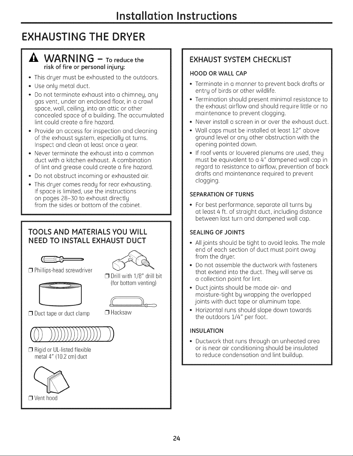
TOOLS AND MATERIALS YOU WILL
NEED TO INSTALL EXHAUST DUCT
[] Phillips-head screwdriver
[] Duct tape or ductclamp
[] Drill with 1/8" drill bit
(for bottom venting)
[] Hacksaw
(0)))i)))))))))))))))
[] Rigid or UL-listed flexible
metal 4" (10.2 cm)duct
[] Vent hood
SEALING OF JOINTS
• All joints should be tight to avoid leaks. The male
end of each section of duct must point away
from the dryer.
• Do not assemble the ductwork with fasteners
that extend into the duct. They will serve as
a collection point for lint.
• Duct joints should be made air- and
moisture-tight by wrapping the overlapped
joints with duct tape or aluminum tape.
• Horizontal runs should slope down towards
the outdoors 1/4" per foot.
INSULATION
• Ductwork that runs through an unheated area
or is near air conditioning should be insulated
to reduce condensation and lint buildup.
24
Page 25
Installation Instructions
USING FLEXIBLE METAL DUCT
FOR TRANSITION VENTING
Rigid or semi-rigid metal ducting is
recommended for use as transition ducting
between the dryer and the wall. In special
installations when it is impossible to make a
connection with the above recommendations, then
a UL-listed flexible metal transition duct mall be
used between the drLler and wall connection onlLI.
The use of this ducting will affect drLI time. OnlLI
those foil-type flexible ducts, if any, specificallLI
identified for use with the appliance by the
manufacturer should be used. In the United States,
the duct must comply with the Outline for Clothes
Drger Transition Duct, Subject 2158A.
If flexible metal transition duct is necessarLI,
the following directions must be followed:
• Use the shortest length possible. The total length
of flexible metal duct shall not exceed 2.4 m.
• Stretch the duct to its maximum length.
• Do not crush or collapse.
• Never use flexible metal ducting inside the wall
or inside the drLler.
• Avoid resting the duct on sharp objects.
• Venting must conform to local building codes.
DO NOT:
• DO NOT bend or
collapse ducting.
Use elbows if
turns are
necessarLI.
• DO NOT use
excessive
exhaust length.
Cut duct as short
as possible.
• DO NOT crush
duct against
the wall.
FOR TRANSITION VENTING
(DRYER TO WALL}, DO:
• DO cut duct
4
Elbows
as short as
possible and
install straight
into wall.
• DO use elbows
when turns are
necessarg.
• DO NOT set
drger on duct.
25
Page 26
Installation Instructions
EXHAUSTING THE DRYER IcontJ
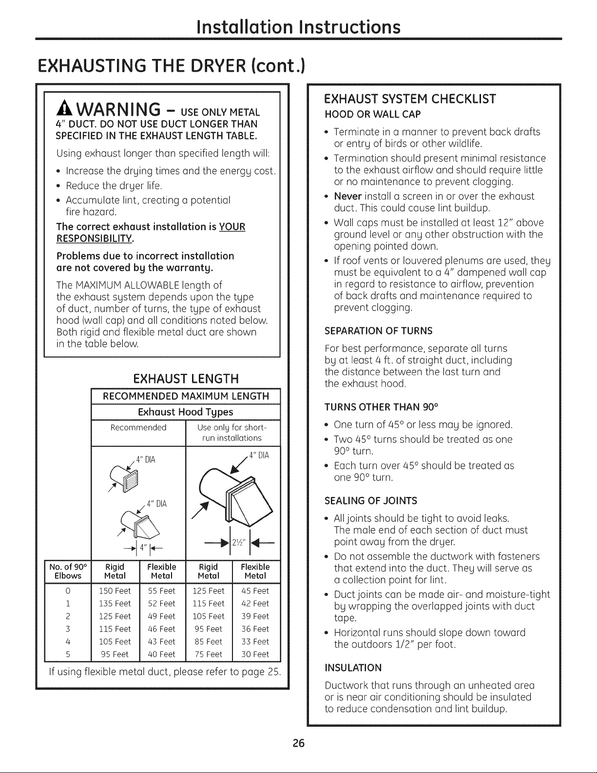
WARNING - USEONLYMETAL
4" DUCT. DO NOT USE DUCT LONGER THAN
SPECIFIED IN THE EXHAUST LENGTH TABLE.
Using exhaust longer than specified length will:
• Increase the drging times and the energg cost.
• Reduce the drger life.
• Accumulate lint, creating a potential
fire hazard.
The correct exhaust installation is YOUR
RESPONSIBILITY.
Problems due to incorrect installation
are not covered bg the warrantg.
The MAXIMUM ALLOWABLE length of
the exhaust sgstem depends upon the tgpe
of duct, number of turns, the tgpe of exhaust
hood (wall cap) and all conditions noted below.
Both rigid and flexible metal duct are shown
in the table below.
EXHAUST LENGTH
RECOMMENDED MAXIMUM LENGTH
Exhaust Hood Types
Recommended Useonly for short-
run installations
EXHAUST SYSTEM CHECKLIST
HOOD OR WALL CAP
• Terminate in a manner to prevent back drafts
or entrg of birds or other wildlife.
• Termination should present minimal resistance
to the exhaust airflow and should require little
or no maintenance to prevent clogging.
• Never install a screen in or over the exhaust
duct. This could cause lint buildup.
• Wall caps must be installed at least 12" above
ground level or ang other obstruction with the
opening pointed down.
• If roof vents or Iouvered plenums are used, theg
must be equivalent to a 4" dampened wall cap
in regard to resistance to airflow, prevention
of back drafts and maintenance required to
prevent clogging.
SEPARATION OF TURNS
For best performance, separate all turns
bg at least 4 ft. of straight duct, including
the distance between the last turn and
the exhaust hood.
TURNS OTHER THAN 90 °
• One turn of 45° or less mag be ignored.
• Two 45° turns should be treated as one
90 ° turn.
• Each turn over 45° should be treated as
one 90° turn.
4" DIA
No. of 90 ° Rigid Flexible Rigid Flexible
Elbows Metal Metal Metal Metal
0
!
2
3
4
5
150 Feet
135 Feet
125 Feet
115 Feet
105 Feet
95 Feet
55 Feet 125 Feet
52 Feet 115 Feet
49 Feet 105 Feet
46 Feet 95 Feet
43 Feet 85 Feet
40 Feet 75 Feet
45 Feet
42 Feet
39 Feet
36 Feet
33 Feet
30 Feet
If using flexible metal duct, please refer to page 25.
SEALING OF JOINTS
• All joints should be tight to avoid leaks.
The male end of each section of duct must
point awag from the drger.
• Do not assemble the ductwork with fasteners
that extend into the duct. Theg will serve as
a collection point for lint.
• Duct joints can be made air- and moisture-tight
bg wrapping the overlapped joints with duct
tape.
• Horizontal runs should slope down toward
the outdoors 1/2" per foot.
INSULATION
Ductwork that runs through an unheated area
or is near air conditioning should be insulated
to reduce condensation and lint buildup.
26
Page 27
Installation Instructions
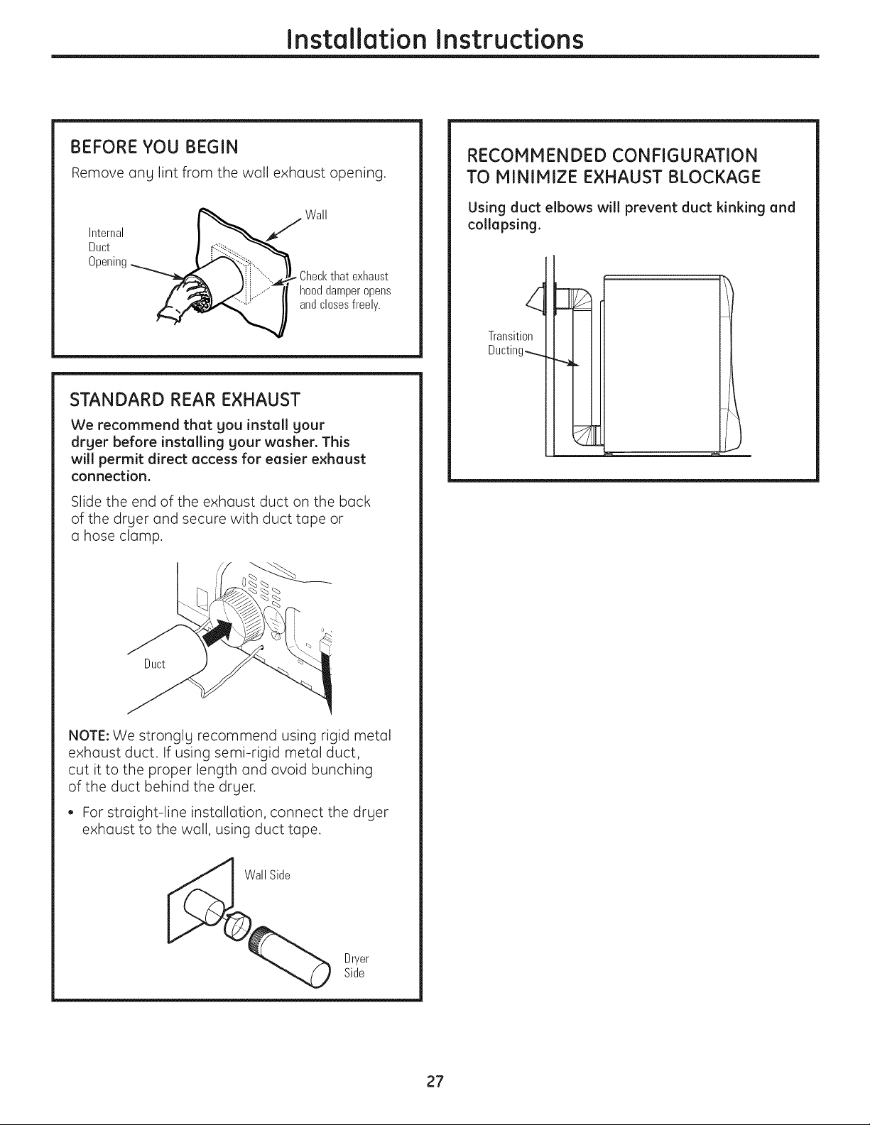
BEFORE YOU BEGIN
Remove ang lint from the wall exhaust opening.
Wall
Internal I _J
Duct I _ ........"_----------------_
Opening_:_i,,.
¥i - ..... Checkthat exhaust
f',_ .i,/:.- ..........." hood damper opens
andclosesfreely.
STANDARD REAR EXHAUST
We recommend that you install your
dryer before installing your washer. This
will permit direct access for easier exhaust
connection.
Slide the end of the exhaust duct on the back
of the drger and secure with duct tape or
a hose clamp.
RECOMMENDED CONFIGURATION
TO MINIMIZE EXHAUST BLOCKAGE
Using duct elbows will prevent duct kinking and
collapsing.
Transition
Ducting_
Duct
NOTE: We stronglg recommend using rigid metal
exhaust duct. If using semi-rigid metal duct,
cut it to the proper length and avoid bunching
of the duct behind the drger.
• For straight-line installation, connect the drger
exhaust to the wall, using duct tape.
Dryer
Side
27
Page 28

Installation Instructions
EXHAUSTING THE DRYER (cont.)
SIDE VENTING:
Dryer Exhaust to right of cabinet for Electric
models only.
Dryer Exhaust to left of cabinet for Gas and
Electric models.
WARNING - BEFORE
PERFORMING THIS EXHAUST INSTALLATION,
BE SURE TO DISCONNECT THE DRYER FROM ITS
ELECTRICAL SUPPLY. PROTECT YOUR HANDS
AND ARMS FROM SHARP EDGES WHEN
WORKING INSIDE THE CABINET. BE SURE
TO WEAR GLOVES.
Remove
screw
and save
\
Detach and remove the bottom, right or left side
knockout as desired. Remove the screw inside the
drger exhaust duct and save. Pull the duct out of
the drger.
Right
Left
Bottom
Removedesired
knockout(oneonly)
ADDING A NEW DUCT
Fixinghole Portion"A"
.' 1%4 :
L
exhaust
Reconnect the cut portion (A)of the duct to the
blower housing. Make sure that the shortened duct
is aligned with the tab in the base. Use the screw
saved previously to secure the duct in place
through the tab on the appliance base.
ADDING ELBOW AND DUCT FOR EXHAUST
TO LEFT OR RIGHT SIDE OF CABINET
Internalduct
Rearopening
• Insert the 4" elbow through the rear opening and
connect the elbow to the drger internal duct.
Fixinghole
\
I_ 13sA''
Cut the duct as shown and keep portion A.
TAB LOCATION
Notfor gas
Bendtab
up45°
Through the rear opening, locate the tab in the
middle of the appliance base. Lift the tab to about
45°,using a flat-blade screwdriver.
Sideopening
• Insert the 4" duct through the side opening
and connect it to the elbow.
CAUTION: Do not pullor demege the
electricel wires end do not remove the vingl cover
from the electricel components inside the drger
when inserting the duct. A slight interference
meg occur between the e×heust end the wire
components.
28
Page 29
Installation Instructions
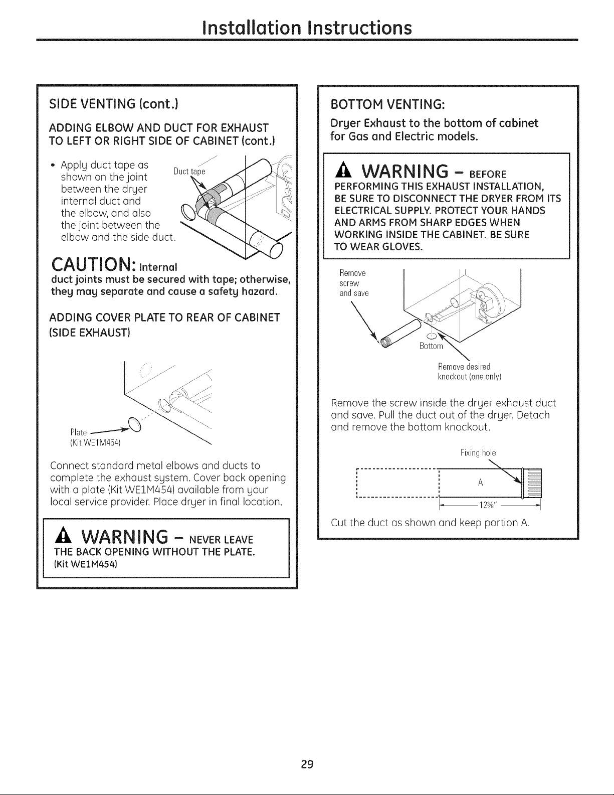
SIDE VENTING (cont.)
ADDING ELBOW AND DUCT FOR EXHAUST
TO LEFT OR RIGHT SIDE OF CABINET (cont.)
• Apply duct tape as
shown on the joint
between the dryer
internal duct and
the elbow, and also
the joint between the "
elbow and the side duct.
Duct
CAUTION: Internal
duct joints must be secured with tape; otherwise,
theg mag separate and cause a safetg hazard.
ADDING COVER PLATE TO REAR OF CABINET
(SIDE EXHAUST)
BOTTOM VENTING:
Drger Exhaust to the bottom of cabinet
for Gas and Electric models.
-A WAR NING - BEFORE
PERFORMING THIS EXHAUST INSTALLATION,
BE SURE TO DISCONNECT THE DRYER FROM ITS
ELECTRICAL SUPPLY. PROTECT YOUR HANDS
AND ARMS FROM SHARP EDGES WHEN
WORKING INSIDE THE CABINET. BE SURE
TO WEAR GLOVES.
Remove
screw
and save
X,
Bottom
Removedesired
knockout(oneonly)
Connect standard metal elbows and ducts to
complete the exhaust system. Cover back opening
with a plate (Kit WEIM454) available from your
local service provider. Place dryer in final location.
-A WARNING - NEVERLEAVE
THE BACK OPENING WITHOUT THE PLATE.
(Kit WEIM454)
Remove the screw inside the dryer exhaust duct
and save. Pull the duct out of the dryer. Detach
and remove the bottom knockout.
Fixinghole
..................... A
123A'' _I
Cut the duct as shown and keep portion A.
29
Page 30
Installation Instructions
EXHAUSTING THE DRYER (cont.)
BOTTOM VENTING (cont.}
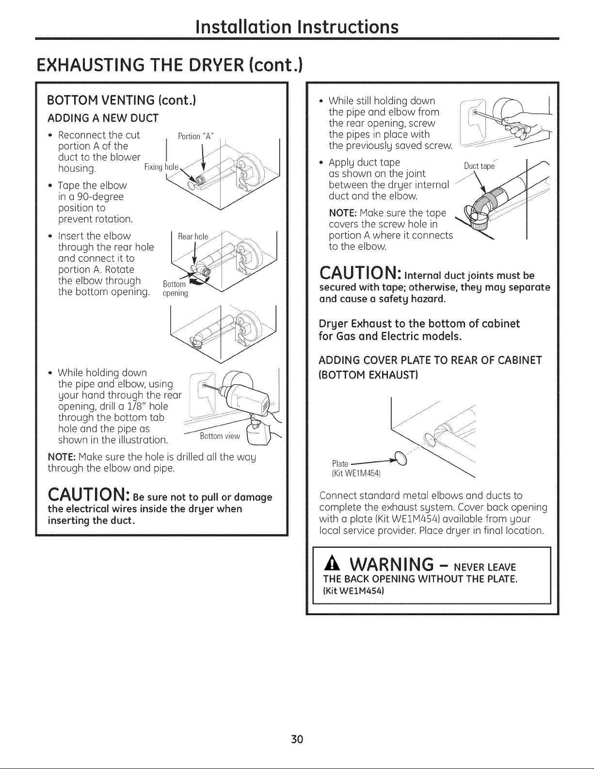
ADDING A NEW DUCT
Reconnect the cut
portion A of the
duct to the blower
housing,
Tape the elbow
in a 90-degree
position to
prevent rotation.
Insert the elbow
through the rear hole
and connect it to
portion A. Rotate
the elbow through
the bottom opening.
While holding down
the pipe and elbow, using
your hand through the rear
opening, drill a 1/8" hole
through the bottom tab
hole and the pipe as
shown in the illustration.
Fixinghole
Portion"A"
Rearhole
Bottom
opening
While still holding down
the pipe and elbow from
the rear opening, screw
the pipes in place with
the previously saved screw.
Apply duct tape Ducttape
as shown on the joint _ _<"
between the drger internal
duct and the elbow.
NOTE: Make sure the tape
covers the screw hole in
portion A where it connects
to the elbow.
CAUTION: Internalductjoints mustbe
secured with tape; otherwise, theg mag separate
and cause a safetghazard.
Dr£1er Exhaust to the bottom of cabinet
for Gas and Electric models.
ADDING COVER PLATE TO REAR OF CABINET
(BOTTOM EXHAUST)
Bottomview
NOTE: Make sure the hole is drilled all the wag
through the elbow and pipe.
CAUTION: Be sure not to pullor damage
the electrical wires inside the drger when
inserting the duct.
Connect standard metal elbows and ducts to
complete the exhaust sgstem. Cover back opening
with a plate (Kit WE1M454) available from gour
local service provider. Place drger in final location.
WARNING - NEVERLEAVE
THE BACK OPENING WITHOUT THE PLATE.
(Kit WEIM454)
3O
Page 31

FINAL SETUP
Installation Instructions
[] LEVEL THE DRYER
Stand the dryer upright near the final location and
adjust the four leveling legs at the corners to ensure
that the dryer is level from side to side and front
to rear.
Raise Lower
[_[]ATTACH SERIAL CABLE
Attach the serial cable for washer and dryer
connection to the serial port on the back of
the dryer.
Attach the other end of the cable to the washer
before pushing the washer into its final position.
[_] GROUNDING INSTRUCTIONS
This appliance must be grounded. In the event
of malfunction or breakdown, grounding will
reduce the risk of electric shock by providing
U path of least resistance for electric current.
This appliance is equipped with U cord having on
equipment-grounding conductor and a grounding
plug. The plug must be plugged into an appropriate
outlet that is properly installed and grounded in
accordance with all local codes and ordinances.
r_ DRYER STARTUP
Press the POWER button.
POWER
NOTE: If the dryer has been exposed to
temperatures below freezing for an extended
period of time, allow it to warm up before pressing
POWER. Otherwise, the display will not come on.
The dryer is now ready for use.
r_ PLUG DRYER IN
z-'__:::_I _ I "ground exists
SerialPort
'_!_,Ensure proper
L__J beforeuse.
Rearof
Dryer
SERVICING
-AWARNING - Labelallwiresprior
to disconnection when servicing controls. Wiring
errors can cause improper and dangerous
operation after servicing/installation.
For replacement parts and other information,
refer to the buck cover for servicing phone
numbers.
31
Page 32

Installation Instructions
REVERSINGTHE DOOR SWING (if desired}
IMPORTANT NOTES
• Read the instructions all the way through before
starting.
• Handle parts carefully to avoid scratching paint.
• Provide a non-scratching work surface for
the doors.
• Set screws down by their related parts to avoid
using them in the wrong places.
• All screws must be hand-tightened.
• Normal completion time to reverse the door
swing is :30-60 minutes.
IMPORTANT: Once you begin, do not move the
cabinet until door-swing reversal is completed.
These instructions are for changing the hinges
from the right side to the left side-if you ever want
to switch them back to the right side, follow these
same instructions and reverse all references
to the left and right.
STANDARD REVERSIBILITY KIT
[] Chromedoor cap f/,_
[] Chromedoor hinge cap
[] Inner door cap
[] 2 Plugbuttons
TOOLS YOU WILL NEED
[] Phillips-head screwdriver
[] Putty knife or thin-blade screwdriver
U
[] Pliers
32
Page 33

DOOR PARTS
Installation Instructions
£
[] Hinge cap
[] Hinge assembly
[] Outer handle
[] Chromedoor cover
[] Chromedoor cap
[] Inner door cap
[] C Small tapping screw
1 - #8 x 0.375"
[] D Small tapping screws
11 - #8x 0.625"
[] E Machine screws
4 - #8 x 0.50"
[] Inner handle
[]2 Handle caps
[] A Largetapping screws
7 -#10 x 1.125"
[] B Largetapping screws
2 - #10 x 0.750"
33
Page 34

Installation Instructions
REVERSINGTHE DOOR SWING (if desired}
BEFORE YOU START
Unplug the drger from its electrical outlet.
F11REMOVE THE DOOR ASSEMBLY
Remove the side hinge cap bg opening
the drger door and removing the screw from
behind the hinge (#8 x .375" tapping screw). Then
using gout hand, pop the hinge cap off the drger.
F[] REMOVE THE DOOR ASSEMBLY {cont.}
Hold the door and remove the 2 hinge screws
(#10 x 0.75" tapping screws). Pull the door awag
from the drger front panel.
/ i
/' i
// I
t
/ i
i
/ i
// i
[_] DISASSEMBLE THE DOOR ASSEMBLY
Lag the door down on a soft, protected, flat
surface so that the inner part faces upward
(door resting on the handle side).
Remove the 7 screws (#10 x :L125" tapping
/
Hinge
screws) located around the perimeter of the door.
Turn the door assemblg over and separate
the chrome cover from the inner door. Put
the inner door aside on a soft, protected flat
surface.
34
Page 35

Installation Instructions
[_] REVERSE DOOR HANDLE
AND CAPS
A Lay the chrome cover down on a soft,
protected, flat surface so that the inner part
faces upward (resting on the handle side).
Disassemble the door cap from the chrome
cover on the handle side by removing 2 screws
(#8 x 0.625" tapping screws).
2xD
Screws
Doorcap
B Disassemble the inner handle from the outer
handle bg removing 3 screws (#8 x 0.625"
tapping screws). Disassemble the outer handle
from the chrome cover bg removing 4 screws
(#8 x 0.625" tapping screws).
[_] REVERSE DOOR HANDLE
AND CAPS (CONT.}
C Pop the 2 handle caps out toward you and
reassemble on the opposite side of the chrome
cover, where gou removed the outer handle.
D Assemble the outer handle onto the opposite
side of the chrome cover, using 4 screws
(#8 x 0.625" tapping screws).
3xD
Screws
(inner
_ndle)
Outer
handle
Outer
handle
35
Page 36

Installation Instructions
REVERSINGTHE DOOR SWING (if desired}
[_] REVERSE DOOR HANDLE
AND CAPS {CONT.}
E Reassemble the inner handle to the outer handle,
using 3 screws (#8 x 0.625" tapping screws).
Inner
handle
F Assemble the new right-side door cap
(from reversibility kit), using 2 screws
(#8 x 0.625" tapping screws).
F_ REVERSE HINGE AND CAPS
• Lag the inner door down on a soft, protected
flat surface so that the inner part faces up.
• Remove the 2 black plug buttons on the opposite
side of the hinge, using a putts knife or thin-blade
screwdriver.
• Disassemble the inner door cap from the inner
door bg removing 2 screws (#8 x 0.75" tapping
screws).
Disassemble the hinge from the inner door
bg removing 4 screws (#8-32 x 0.50" machine
screws).
Innerdoor
>2xD
Screws
Doorcap
Put the chrome cover aside on a soft, protected
flat surface.
• Assemble the hinge to the opposite side
of the inner door, using 4 screws (#8-32 x 0.50"
machine screws).
Assemble the new inner door cap (from
reversibilitg kit) on the opposite side of the hinge,
using 2 screws (#8 x 0.75" tapping screws).
Install the 2 black plug buttons on the opposite
side of the hinge in the 2 remaining holes.
Replace
2xD
screws
Inner
doorcap
36
Page 37

Installation Instructions
[_] REASSEMBLE DOOR ASSEMBLY
Turn the inner door
over and place on
a soft, protected
flat surface so that
the inner part is facing
down. Assemble
the chrome cover
to the inner door by
placing them together.
Flip the door assembly over and assemble, using
7 screws (#10 x 1.125" tapping screws).
[Z] REINSTALL DOOR ASSEMBLY
Place the door back on the dryer front panel,
making sure the latch is engaged and the hinge
is sitting in the two openings in the dryer front.
Assemble the door to the front cabinet, using
2 screws (#10 x 0.75" tapping screws).
Install the new left-hand hinge cap (from the
reversibility kit) onto the hinge, by opening the
dryer door and screwing the hinge cap into place.
[] REVERSE FRONT PANEL PLUG
BUTTONS AND STRIKE PLATE
Remove the 2 plug buttons on the dryer front
panel, using a putty knife or other flat tool as
shown, and reinstall on the opposite side. Switch
the strike bracket and its cover by removing
2 screws (#8 x 0.625" tapping screws) for each
and reinstalling on opposite sides.
2 Plug
buttons
Protective
piece of tape
Strike
bracket
NOTE:Save the remaining caps and covers in case
you want to reverse the hinge again.
Hinge cap
1x CScrew
in hingecap
-_b..-.-.
NOTE: Apply a protective piece of tape to the side
of the plug button where the putty knife blade will
be inserted to prevent scratching.
37
Page 38

Installation Instructions
STACKING THE WASHER AND DRYER(if desired)
BEFORE YOU BEGIN
Read these instructions completely and carefully.
• IMPORTANT- Save theseinstructions
for local electrical inspector's use.
• IMPORTANT-Observeallgoverning
codes and ordinances.
• Note to Installer - Be sure to leave these
instructions with the Consumer.
• Note to Consumer - Keep these instructions
for future reference.
• Service must be performed by a qualified
installer.
• Proper installation is the responsibility of
the installer.
FOR YOUR SAFETY:
WARNING -
Electric Shock Hazard. Disconnect power before
installing. Failure to do so could result in serious
injurg or death.
Potential Personal Injurg. More than two people
are recommended to lift the drger into position
because of its weight and size. Failure to do so
could result in personal injurg or death.
Avoid Tipping and Rupture of UtilitLI Services.
DrLler must be securelg attached to the washer.
DO NOT place the washer on top of the drger.
Failure to do so could result in personal
injurg/death or propertLI damage.
Mobile Home or Manufactured Home
Installation - Stacking of a gas drger is not
permitted in a mobile home or manufactured
home.
MINIMUM CLEARANCE OTHER THAN
ALCOVE OR CLOSET INSTALLATION
Minimum clearance to combustible surfaces
and for air opening are: 0" both sides, 1" front
and 3" rear. Consideration must be given to provide
adequate clearance for installation and service.
REQUIREMENTS FOR ALCOVE OR
CLOSET INSTALLATION
• Your drLler is approved for installation in
an alcove or closet, as stated on a label on
the drger back.
• The drLler MUST be vented to the outdoors. See
the EXHAUSTING THE DRYERsection.
• Minimum clearance between drger cabinet and
adjacent walls or other surfaces is:
0" either side
3" front and rear
• Minimum vertical space from floor to overhead
shelves, cabinets, ceilings, etc., is 52".
• Closet doors must be Iouvered or otherwise
ventilated and have at least 60 square inches
of open area equallg distributed. If the closet
contains both a washer and a drLler, doors must
contain a minimum of 120 square inches of open
area equallg distributed.
• The closet should be vented to the outdoors
to prevent gas pocketing in case of gas in the
supplg line.
• No other fuel-burning appliance shall be
installed in the same closet with the drger
(gas models onlg).
NOTE: WHEN THE EXHAUST DUCT IS LOCATEDAT
THE REAR OF THE DRYER, MINIMUM CLEARANCE
FROM THE WALL IS 5.5 INCHES.
38
Page 39

Installation Instructions
KIT CONTENTS
i
[] Right hand bracket
[] Left hand bracket
[] 4 rubber pads
TOOLS YOU WILL NEED
[] 4 #12 x 1" screws
[] 4 #8 x 1/2" screws
INSTALLINGTHE STACK
BRACKETKIT
I_ REMOVE THE DRYER LEVELING LEGS
A. Carefully lay the dryer on its side. Use the
packing material so you don't scratch the finish
on the dryer.
B. Use an open-end wrench or pliers to remove
the dryer leveling legs.
[] Phillips screwdriver
[] Gloves
[] Open-endedwrench
[] Pliers
[] Level
INSTALLATION PREPARATION
Remove the packaging.
Flatten the product carton to use as a pad to lay
the dryer down on its side. Continue using the
carton to protect the finished floor in front of
the installation location.
Backout andremove
all 4 levelinglegs
I
[_] INSTALL RUBBER PADS
TO DRYER BASE
Locate the 4 rubber pads in the parts package.
Remove the adhesive backing and firmly place
over on the bracket where you removed the
leveling legs.
39
Page 40

Installation Instructions
STACKINGTHEWASHERAND DRYER(if desired} (cont.)
[_] INSTALL BRACKET TO DRYER
A,
Align the holes in the left bracket with the holes
in the bottom left corner of the drger. Use a
Phillips screwdriver to install the 2 #12 x 1"
tapping screws.
B,
Repeat the above step with the right bracket
on the bottom right corner of the drger.
C. Set the drger upright.
NOTE: Make sure to set the drger on a piece of
packing material so the brackets that are attached
to the bottom of the drger do not damage the floor.
ioi
i
[] INSTALL DRYER AND BRACKET
ON WASHER
r_ FINALIZE THE INSTALLATION
A. Refer to the washer Installation Instructions
to complete the washer installation.
B,
Refer to the drger Installation Instructions
to complete the drger installation.
C,
Carefullg slide or walk the stacked washer and
drger into place. Use felt pads or other sliding
device to assist moving and to protect flooring.
-AWAR NING - PotentialPersonal
Injury. Do not push on the dryer once installed
to top of the washer. Pushing on the dryer mag
result in pinched fingers.
Place ___"
hands
here_
00° tl:
Place
hands
"_-here
A,
Lift the drger on top of the washer. Be careful
not to scratch the top of the washer with the
brackets. Protect the washer control panel with
cardboard or other protection. Be sure to lift
the drger high enough to clear the washer
control panel.
_ZIWARNING - Potential
Personal Injury. More than two people are
recommended to lift the dryer into position
because of its weight and size. Failure to do
so could result in personal injury or death.
B. Align the holes in the bracket with the holes
in the back of the washer. Using a Phillips
screwdriver, attach the 2 #8 x 1/2" tapping
screws. Repeat on both sides of the washer.
/
4O
Page 41

Installation Instructions
INSTALLINGTHE PEDESTAL(if desired}
-ACAUTION - Duetothesizeandweight of
these products, and to reduce the risk of personal
injury or damage to the product, TWO PEOPLE ARE
REQUIRED FOR PROPER INSTALLATION.
KIT CONTENTS
[] 4 Support pads
[] Drawer divider
[] 4 Mountingscrews
TOOLS YOU WILL NEED
[] Phillips-head
screwdriver
[] 7 mm Socketwrench
INSTALLATION PREPARATION
Remove the packaging.
The drawer divider is taped at the top of the
shipping carton. Remove the divider and set aside
for final installation.
Flatten the product carton to use as a pad to lay
the washer or dryer down on its side. Continue
using the carton to protect the finished floor in front
of the installation location.
REMOVE THE LEVELING LEGS
r_ carefully lay the washer or dryer on its side
to access the leveling legs on the bottom of
the appliance.
IMPORTANT: Do not lay the washer or dryer on
its back! Do not remove the shipping bolts on the
back side of the washer. The bolts must remain in
place until the washer is returned to an upright
position.
r_ use an open-end wrench to remove the
washer or dryer leveling legs.
[] 9/16" Open-endwrench
or adjustable wrench
Backoutand remove
all 4 levelinglegs
41
Page 42

Installation Instructions
INSTALLINGTHE PEDESTAL(if desired} (cont.)
PREPARETHE PEDESTAL
Pull the drawer
out as far as it
will go.
Remove screws
@
from drawer
slides. Slide
drawer out of
the base and
set aside.
FOR DRYERSONLY:
Locate the 4 support pads from the parts
D
package. Each pad has 2 protrusions that fit
into the holes on top of the pedestal. Press the
rubber pads into each set of corner holes on
the top of the pedestal as shown.
INSTALL THE PEDESTAL
TO THE WASHER OR DRYER
@
Place the pedestal against the bottom
of the unit. Check to be sure the drawer front
is at the front of the washer.
@
Align the holes in the pedestal with the
holes in the bottom of the unit. Use a Phillips
screwdriver to install the 4 bolts through the
pedestal and into the unit-do not tighten.
@
II
@
NOTE: The support pads should be installedon
the drger onl9. DO NOT INSTALL THESE PADS ON
THE WASHER PEDESTAL.
r_ Slide the pedestal toward the unit, until it is
aligned front to back. Use a 7 mm socket
wrench to securelg tighten the bolts.
42
Page 43

Installation Instructions
LEVEL THE WASHER OR DRYER
[]
Stand the washer or dryer upright. Move it
close to its final location.
Make sure that the washer or dryer is level
@
by placing a level on top. Check side to side
and front to back.
B]
Use an open
ended wrench
to adjust the
legs in and out.
Tighten the lock
nut against
the bottom
of the pedestal.
NOTE: To minimize vibration, the locking nuts
must be tight.
/
/
/
REINSTALL THE DRAWER
Check to
be sure the
slides are
closed.
[_ REMOVE SHIPPING SCREWS
Remove the 4 shipping screws on the back side
of the washer.
E_ FINALIZE THE INSTALLATION
Refer to the washer or dryer Installation Instructions
to complete the installation.
[_ Slide the
drawer
into the Drawer
opening.
Align the
drawer
supports to the
slides on each
side.
r_ Reinstall the original screws into each drawer
slide. Tighten both screws.
r_ open the drawer fully. Slide drawer divider
into slots in the center of the drawer. The
drawer should slide smoothly when you push
it closed.
43
Page 44

Before you call for service...
gave time and money! Review the charts on the following pages,
Troubleshooting Tips
'_ or visit ge.com Youma_t not need to call for service.
PROBLEM Possible Causes What To Do
Dryer shakes or Someshaking/noise is normal. • Hovedryer to an even floor space,or adjust leveling legs
makes noise Dryer may be sitting unevenly as necessary until even.
Clothes take too long Improper or obstructed ducting • Checkthe Installation Instructions to make sure the
to dry dryer venting is correct.
• Hake sure ducting isclean, free of kinksand
unobstructed.
o
Checkto see if outside wall damper operates easily.
Improper sorting
Large loads of heavy fabrics
(likebeachtowels)
Controlsimproperly set
Lint filter is full
Blown fuses or tripped circuit •
breaker
Overloading/combining loads •
Separate heavy items from lightweight items(generally,
a well-sorted washer load is a well-sorted dryer load).
Large,heavy fabrics contain more moisture and take
longer to dry. Separatelarge,heavy fabrics into smaller
loadsto speed drying time.
Hatch control settings to the load you are drying.
Cleanlint filter before every load.
Replacefusesor reset circuit breakers.Sincemost
dryers use 2 fuses/breakers,make sure both are
operating.
Donot put more than one washer load in the dryer at
a time.
Underloading • If you are drying only one or two items,add a few items
to ensureproper tumbling.
TheDRYdryness level Loadconsists of a mixture • When combining heavy and light fabrics in a load,
was chosen but load is of heavy and light fabrics choose NOREDRY
still damp
Exhaust system is blocked • Inspect and clean exhaust system.
Control pads not Controls accidentally put in • PressSTART/PAUSE.
responding servicemode
Controls accidentally put in • Holdthe LOCKbutton for ] secondsto unlock the dryer.
lock mode
Controls performed an • Resetthe in-house breaker.
incorrect operation
Dryer doesn't start Control panel is"asleep" • Thisisnormal. PressPOWERto activate the control panel.
Dryer is unplugged • Makesure the dryer plug is pushedcompletely into
Fuse is blown/circuit breaker • Checkthe building's fuse/circuit breaker box and
is tripped replacefuse or reset breaker.NOTE:Electricdryers
Dryer was acddentally paused • Ifthe light on the START/PAUSEbutton isflashing,
when starting Delay Start the dryer ispaused. PressSTART/PAUSEtorestart
the outlet.
usetwo fusesor breakers.
the countdown.
No numbers displaged Dryer is continuously • Thisis normal. When the dryer senses a low levelof
during cycle, only lights monitoring the amount of moisture in the load,the dryer will display the dry time
44
moisture in the clothes remaining.
Page 45

ge.com
PROBLEM
Time Remaining
jumped to a
lower number
Cannot make a
selection and the
dryer beepstwice
Possible Causes
Theestimated time may change
when a smaller load than usual
isdrying
The DRYNESSLEVEL,TEMP
or OPTIONthat you are
trying to select is incompatible
What To Do
• Thisis normal.
Thisis normal.
with the chosen dry cycle
Dryer is running but
O0is displayed in
Time Remaining
Clean Lint Filter (message) POWER button was activated • PressSTART/PAUSEtobegin a dry cycle and the message
The EXTENDTUMBLE
option was chosen
Thisis normal. During extended tumbling, the time
remaining is not displayed.The extended tumbling
option lastsapproximately 20 minutes.
will disappear.
Dryer doesn't heat
Fuse is blown/circuitbreaker
istripped; the dryer may tumble
but not heat
Checkthe building's fuse/circuit breaker box and
replaceboth fuses or reset both breakers.Yourdryer
may tumble ifonly one fuse is blown or onebreaker
tripped.
Gas service isoff
• Makesure gas shutoff at dryer and main shutoff are
fully open.
LPgassupplytankisempty
ortherehasbeena utility
Refillor replace tank. Dryer should heat when utility
service isrestored.
interruptionofnaturalgas
(gasmodels)
Inconsistent drying times Typeofheat
Drying time will vary according to the type of heat used.
If you recently changed from an electric to a gas
(natural or LP)dryer,or vice versa,the drying time
could be different.
Type ofload and
dryingconditions
• Theload size,types of fabric,wetness of clothes and the
length and condition ofthe exhaust system will affect
drying times.
Glow at the rear
of the drum
Heaters behind the drum
• Thisis normal. Under certain drying conditions and
room ambient lighting,the glow of the heaters may be
visible at the rear of the drum.
Clothes are still wet
and dryer shut off
after a short time
The door was opened mid-cycle.
The load was then removed from
the dryer and a new load put in
withoutselectinga new cycle
• A dry cycle must be reselected each time o new load
isput in.
Small load • When drying 3 items or less,choose SPEEDDRYor
TIMEDDRY.
Load was already dry except • ChooseSPEEDDRYorTIMEDDRYto dry damp collars
for collars and waistbands and waistbands. Inthe future,when drying a load with
collors and waistbonds, choose MOREDRY.
Dryer is not level • Movedryer to an evenfloor space or adjust leveling legs
as necessary until even.
Clothes are wrinkled Overdrging • Selecta shorter drying time.
Removeitems while they still hold a slight amount of
moisture.Selecta LESSDRYor DAMPsetting.
Letting items sit in dryer after • Removeitems when cycle ends and fold or hang
cycle ends immediately, or use the EXTENDTUMBLEoption.
Overloading • Separate large loads into smaller ones.
45
Page 46

Before gou call for service...
gave time and money! Review the charts on the following pages,
_ roubleshooting Tips
PROBLEM Possible Causes What To Do
or visit ge.com. You may not need to call for service.
Clothes shrink Some fabrics will naturally shrink •
when washed. Others can be
safely washed, but will shrink
in the dryer
Toavoid shrinkage, follow garment care labelsexactly.
o
Someitems may be pressed back into shape after drying.
If you are concerned about shrinkagein a particular
item,do not machine wash ortumble dry it.
Greasy spots on clothes Improper use of fabric softener • Follow directionson fabric softener package.
Drying dirty items • Useyour dryer to dry only clean items. Dirty items can
with clean ones stain clean items and the dryer.
Clothes were not • Sometimesstains which cannot be seen when the
completely clean clothesare wet appear after drying. Use proper washing
procedures before drying.
Lint on clothes Lint filter is full • Cleanlint screen beforeeach load.
Improper sorting • Sortlint producers (likechenille)from lint collectors
(likecordurog).
Static electricity can attract lint • Seesuggestions in this section under STATIC.
Overloading • Separatelarge loads into smaller ones.
Paper,tissue, etc., left in pockets • Empty all pocketsbefore laundering clothes.
Static occurs Nofabric softener was used • Try a fabric softener.
o
Bounce®FabricConditioner Dryer Sheetshave been
approved for use in all GEDryers when usedin
accordance with the manufacturer's instructions.
Overdrging
• Try a fabric softener.
• Adjust setting to LESSDRYor DAMP.
Synthetics,permanent press
• Try a fabric softener.
and blendscan cause static
Collars and waistbands
still wet at end of cycle
Slight variation
in metallic color
The drynessmonitorsenses
thatthebody oftheclothes
isdry
This is normal
• ChooseSPEEDDRYor TIMEDDRYto dry damp collars
and waistbands. Inthe future, when drying a loadwith
collars and waistbands, choose lORE DRY.
• Dueto the metallic properties of paint usedfor this unique
product, slight variations of color may occur due to
viewing angles and lighting conditions.
Door is too foggy to see
clothes during a steam
cycle
Water seen on inside of
door and top of tint filter
when opening door after
steam cycle
Steam condenses on inner door • This is normal.
Steam condenses on these
• This isnormal.
surfaces
Small areas on clothes are Steam condenses on inner drum • Selectashorter cycle.
damp after steam cycle
Cycle or cycle time selected too • Manually reduce cycle time for given cycle.
long for sizeof load
46
Page 47

PROBLEM Possible Causes What To Do
Small amount of water Inadequate load size for steam • Select a shorter cycle. Manually reduce cycle time
on floor in front of dryer cgcle selected, excess steam for given cycle.
condenses inside cabinet and
leaks out
Water on floorin back Loose water hose connection to • Tighten connection.
of drger valve
Hose missing rubber washer at • Install rubber washer provided with hose.
connection with valve
Dryer makes water Water valve is open filling steam • This is normal.
noises generator
Steam generator is dispensing • This is normal.
steam into drum
Water drips from door Steam condenses on inner door • This is normal.
when opened after
a Steam Cgcle
ge.com
Cannot see steam at Steam released at different • This is normal.
beginning of cycle time in cycle
Garments still wrinkled Too many garments • Load fewer garments; manually increase time.
after steam cycle
Drger continues to Extend Tumble was selected • Ensure Extend Tumble option is not selected.
tumble after display
sags Complete
47
Page 48

Notes.
0
0
0
0
0
E
0
L_
48
Page 49

GE Dryer Warranty. IForcustomersin the UnitedStates)
All warranty service provided by our Factory Service Centers,
or an authorized Customer Care ®technician. To schedule
service, on-line, visit us at ge.com, or call 800.GE.CARES
(800.432.2737).
Please have serial number and model number available when
calling for service.
We Will Replace:
One Veer
From the date of the
original purchase
Second Veer
From the date oft,he
original purchase
Second through
Fifth Veer
From the date of the
original purchase
IllService trips to sour home to teach SOUhow to use
the product.
Any pert of the drger which failsdue to a defect in materials or workmanship. Duringthis
limited one-year warranty, GEwill alsoprovide, free of charge, all labor and related service costs
to replacethe defective part.
,Anypert of the drger which fails due to a defect in materials or workmanship. During this
additional one-year limited warranty, you will be responsiblefor any labor or related service costs.
The extra-large or super-capacity dryer drum and main electronic control Ooard ifang of these
parts should fail due to a defect in materials or workmanship. During this additional three-year
limited warrants, you will be responsiblefor any labor or related servicecosts.
Staple your receipt here.
Proof of the origina! purchase
date is needed to obtain service
under the warranty.
[] Damage to the product caused bg accident, fire, floods
or acts of God.
[] Improper installation, delivers or maintenance.
[] Failure of the product if it is abused, misused or used for
other than the intended purpose or used commemiallg.
[] Replacement of the light bulb after its expected
useful life.
[] Replacement of house fuses or resetting of circuit
breakers.
EXCLUSION OF IMPLIED WARRANTIES--Your sole end exclusive remedy is product repair us provided
in this Limited Warrants. Any implied warranties, including the implied warranties of merchontobilitg
or fitness for o particular purpose, ore limited to one gear or the shortest period allowed bg low.
This warrant_l is extended to the original purchaser and an_l succeeding owner for products purchased
for home use within the USA. If the product is located in an area where service bbl a GE Authorized Servicer
is not available, blOUmabl be responsible for a trip charge or blOUmabl be required to bring the product to an
Authorized GE Service location for service. In Alaska, the warrant_l excludes the cost of shipping or service calls
to Four home.
Some states do not allow the exclusion or limitation of incidental or consequential damages. This warrantbl
gives _lOUspecific legal rights, and _lOUmabl also have other rights which varbl from state to state. To know
what btour legal rights are, consult btour local or state consumer affairs office or btour state's Attornebt General.
[] Incidental or consequential damage caused bg possible
defects with this appliance.
[] Damage caused after delivers.
[] Product not accessible to provide required service.
Warrantor: General Electric Company. Louisville, KY 40225
49
Page 50

GE Dryer Warranty. IForcustomersinCanada)
All warranty service provided by our Factory ServiceCentres or an authorized
technician. For service, call 1.800.561.3344.
Please have serial number and model number available when calling for service.
We Will Replace:
One Year
From the date of the
origina!purchase
Second Year
From the date of the
originalpurchase
Second through
Fifth Year
From the date of the
originalpurchase
Ill Service trips to gout home to teach gou how to use
the product.
Improper installation, deliverg or maintenance.
m Failure of the product if it is abused, misused or used for
other than the intended purpose or used commemiallg.
m Replacement of the light bulb after its expected
useful life.
Ill Replacement of house fuses or resetting of circuit
breakers.
Any part of the dryer which fails due to a defect in materials or workmanship. Duringthis
limited one-year warranty, GEwill also provide,free of charge, all labor and related servicecosts
to replacethe defective part.
Any port of the dryer which fails due to a defect in materials or workmanship. Duringthis
additional one-year limited warranty, you will be responsiblefor any labor or related service costs.
The e_rudarge or super-capacity dryer drum end main electronic control board if any of these
ports should fail due to o defect in materials or workmanship. During this additional three-year
limited warranty, you willbe responsible for any labor or related service costs.
m Damage to the product caused bg accident, fire, floods
or acts of God.
II Incidental or consequential damage caused bg possible
defects with this epplience.
Ill Damage caused after deliverg.
m Product not accessible to provide required service.
EXCLUSION OF IMPLIED WARRANTIES--Your sole and exclusive remedy is product repair as provided in this Limited
Warranty. Any implied warranties, including the implied warranties of merchantability or fitness for a particular
purpose, are limited to one year or the shortest period allowed by law.
This warranty is extended to the original purchaser and any succeeding owner for products purchased in
Canada for home use within Canada. In-home warranty service will be provided in areas where it is available
and deemed reasonable by Mabe to provide.
50
WARRANTOR IS NOT RESPONSIBLEFORCONSEQUENTIAL DAMAGES.
[
Warrantor: MABE CANADA INC.
i
J
Page 51

Mesures de s_curit_ ....... 52-54
Foncionnement
Caract@istiques ................ 60, 61
Guide de d6marrage ............... 55
Option r6glage ...................... 60
Options de cLlcle ................ 59, 60
Panneau de contr61e ........... 55-58
Utilisation de la s#cheuse .......... 62
installation
Avant de commencer ........... 63, 64
Branchement des bogaux
d'arriv6e ............................ 66
Emplacement
de votre s6cheuse .............. 64, 65
Evacuation de la s6cheuse ..... 74-80
Installation du socle ............. 91-93
Installation finale ................... 81
Inversion de I'ouverture
de la porte ...................... 82-87
Raccordement
d'une s6cheuse 5 gaz ........... 67-70
Raccordement
d'une s6cheuse 61ectrique ...... 71-73
Superposer la s6cheuse
la laveuse .................... 88-90
Conseils de d_pannage ...94-97
Soutienau consommateur
Garantie ........................... 99
Soutien au
consommateur ................... 100
2.
O"
10
N"
CONSERVEZ
Inscrivez ici les num_ros
de mod_le et de s_rie :
Mod_le N °
S_rie N °
Ces informations figurent
sur I'_tiquette situ_e 5 I'avant
de la s_cheuse, derriere la porte.
DIRECTIVES
Q
th
o
o
51
Page 52

MESURESDES :'CURIT :"IMPORTANTES.
LISEZD'ABORDTOUTESLESDIRECTIVES.
,AVERTISSEMENT!
Pour votre s_curit_, suivez les directives fournies dans le present manuel afin
de minimiser les fisques d'incendie, d'explosion et de chocs _lectriques et pr_venir
des d_gSts materiels et des blessures graves ou mortelles.
[] N'entreposez pus ou n'utilisez pas
d'essence ou autres vapeurs ou
liquides inflammables _ proximit_
de cet appareil ou de tout autre
_lectrom_nager.
[] L'installation et les r_parations doivent
_tre effectu_es par un installateur
qualifi_, une entreprise de r_paration
ou votre fournisseur de gaz.
VOUS REMARQUEZ UNE ODEUR DE GAZ :
N'allumez pas d'allumette ou de
agarette, ou ne faites fonctionner
aucun appareil _ gaz ou _lectrique.
N'actionnez aucun interrupteur;
D
n'utilisez aucun t_l_phone dans votre
_difice.
[-31E-vacuez la piece, I'_difice ou
les environs.
Loi californienne sur le contr61e des substances toxiques et de I'eau potable
Cette Ioiexige que le gouverneur de Californie publie une liste de substances reconnues par I'@atcomme @ant
canc@ig@nes,responsables de malformations cong@nitalesou desautres effets nuisibles sur les organes reproducteurs,
et que lesentreprises avertissent les clients de I'exposition potentielle_ ces substances.
Lesappareilsm@nagersfonctionnantaugazpeuventcauseruneexpositionmineure6 quatredecessubstances,6savoir
lebenz@ne,lemonoxgdedecarbone,leformald@hgdeet lasuie,principalementenraisondelacombustionincompl@te
dugaznatureloudugazdep@troleliqudi@.
Ler@glagead@quatde la s@cheuser@duiraau maximum la combustion incompl@e.L'exposition 6 cessubstances peut
@reencore r@duitedavantage en assurant une @vacuationadequate de la s@cheusevers I'ext@ieur.
F_ Appelez imm_diatement votre
fournisseur de gaz en utilisant
le t_l_phone d'un voisin. Suivez
les directives qu'il vous donnera.
[_] Si vous ne pouvezjoindre votre
fournisseur de gaz, appelez
les pompiers.
%
52
UNE INSTALLATIONADdLQUATE
Avant d'utiliser votre s4cheuse, assurez-vous qu'elle a 4t4 ad@uatement install_e, conform_ment
aux Instructions d'installation. Les consignes d'installation figurent au dos de ce manuel.
[]
Mettez rappareil 6 la terre conform@ment6tous
les codeset r@glementsen vigueur. Suivezles Directives
d'installation.
[]
Installezou entreposez I'appareil dans une pi@ce
oOla temperature estsup@ieured O°C,et oO ilsera
d I'abrides intemp@ies.
[]
Branchez rappareil surun circuit prot@g@et de capacit@
appropri@eafin d'@vitertoute surcharge @lectrique.
[]
Retireztous lesarticles d'emballage tranchants etjetez
tousles mat@iaux de transport.
Conduit d _vacuation :
-_ 'air des s6cheuses DOlT@re 6vacu@_ I'ext6rieur pour
-Z] tilisez uniquement des conduits m@talliquesrigides,
Pourdes d6tails complets, suivezles Instructions
d'installation.
I
emp@cherque de grandes quantit6s d'humidit6 et de
charpie soient envog6es dans la pi@ce.
d'un diam@trede4 po,@I'int6rieurde la carrosserie de
la s6cheuse.Utilisez uniquement un conduit m@allique
rigide ou flexible de 4 po de diam@repour I'6vacuation
vers I'ext@rieur.N'utilisezjamais un conduit en plastique
ou autre mat6riau combustible facilement perforable.
Page 53

AVERTISSEM ENT!
AUTOUR DE VOTRESdLCHEUSE
www.electromenagersge.ca
[]
Conservezlazonesousetautourdevosappareilslibre
detousmat@riauxcombustibles(charpies,papiers,
chiffons,etc.),essence,produitschimiquesetautresgaz
etliquidesinflammables.
[]
Gardezlesol propreetsec6 proximit@devos
@lectrom@nagersafindenepasglisser.
[]
IIfaut exercerune@troitesurveillanceIorsque
vousfaitesfonctionnercet appareilen pr@sence
d'enfants.Neleslaissezpasjouersur,avecou
danscetappareiloudanstout autreappareil.
[]
Assurez-vousqu'iln'gait aucuneaccumulation
dechar#e,de poussi@reoudesalet@autour
et6 proximit@derorificed'@acuation.
[]
Gardeztousles produitspourlalessive(comme
lesd@ersifs,lesjavellisants,etc.)horsdelaport@des
enfants,deprd@encedansunearmoireferm@6 clef.
Suiveztouteslesmisesengardesurles@tiquettespour
@iterdesblessures.
[] Nemontezjamaissurledessusdelas@cheuse.
LORSQUEVOUSUTILISEZLA SdLCHEUSE
[] Nevouspenchezjamaisdanslas@cheusependant []
queletambourtourne.Avantdechargeroude
d@chargerlas@cheuseoud'uajouterdesvCtements,
attendezqueletamboursesoitcompl@tementarrCt&
[]
Avantchaques@chage,nettogezlefiltre6 charpieafin
depr@enirI'accumulationdecharpie6 I'int@ieur
delas_cheuseoudansla piece.NEFAITESMS
FONCTIONNERLASECHEUSESANSLEFILTRE
CHARPIE.
[]
Nelavezpasou nefaitespass@cherdesarticlesquiont []
@t@lav@savecdesproduitscombustiblesou explosifs,
ouquiant@t@tremp@sdanscesproduitsouqui ensont
tach@s(cire,peinture,hole,essence,d@graissants,
solvantspourlenett%age6 sec,k_ro@ne,etc.).Ces []
substances@mettentdesvapeursquipeuventprendre
feuou exploser.NeversezpascessubstancesdansI'eau
delalaveuse.N'utilisezpascessubstances6proximit@
devotrelaveuseoudevotres@cheusependantqu'elles
fonctionnent. []
[]
Nerangezpasdansvotres@cheusedesarticlesqui
ont@t@encontactavecdeshuilesdecuisson;ceux-ci
peuventprovoqueruner@actionchimiquesusceptible
defaires'enflammervosvCtements.
[]
IInefaut pasmettredanslas@cheuse,ou(_proximit@
decelle-ci,tout articleagant@t@utilis@avecunsolvant
d@graissantoucontenantunesubstanceinflammable
(commedeschiffonsdenettogage,desvadrouilles,
desserviettesutilis@sdanslessalonsdecoiffure,etc.),
moinsqu'ilsaient_t@d@barrass@sdetoutetraceet
detoutevapeurdesubstanceinflammable.Onutilise
lamaisondenombreuxproduitsinflammables:
ac@tone,alcoold@natur@,essence,k@o@ne,nettogants
m@nagers,d@achants,t@@benthine,cire,d@capants,
contenantdudistillatdep@trole.
[] Lalessivepeutatt@nuerlespropri@t@signifugeantes
destissus.Pour@vitercettesituation,suivez6 lalettre
lesdirectivesdonn@sparlefabricantduvCtement.
Nefaitespass@cherdesarticlescontenantdu
caoutchouc,du plastique,delamousseou autres
mat@iauxsimilaires(commedessoutiens-gorge
prdorm@s,deschaussuresdetennis,descaoutchoucs,
destapisdebain,descarpettes,desbavoirs,desculottes
deb@b@,dessacsdeplastique,desoreillers,etc.),car ces
mat@iauxpeuventfondreoubrOler.Deplus,dans
certainescirconstances,certainsmat@iauxde
caoutchoucpeuventcauserunincendieparcombustion
spontan@Iorsqu'ilssontchauff@s.
Nerangezpasdesarticlesquipeuventfondreou brOler,
commeduplastique,du papier,oudesvCtementssur
ledessusdelas_cheusependantqu'ellefonctionne.
LesvCtementsportantlamention<<Faires_cherloin
delachaleur>>ou <<Nepasfaires_cherparculbutage>>
(commelesgiletsdesauvetagecontenantdu Kapok)
nedoiventpasCtres_ch@sdansvotres_cheuse.
Nefaitespass@cherd'articlesenfibredeverre
dansvotres@cheuse.Lesparticulesqui restentdans
las@cheuseet quipourraientCtrerecueilliespar
lesvCtementsIorsd'uns@chagesubs@quentrisquent
decauserdesirritationscutan@s.
[]
Pourr_duirelesrisquesdechocs@lectriques,
d_brancheztoujoursrappareiloucoupezralimentation
_lectriqueau panneaudedistributionenenlevant
lefusibleouend_clenchantledisjoncteuravantde
ler@areroudelenettoger(saufpourenleveret
nettogerlefiltre6 charpie).RENARQUE:Lefaitd'appuger
surSTART/PAUSE(NISEENNARCHE/PAUSE)ouPOWER
(ALINENTATION]NEcoupeMS I'alimentation@lectrique
6 rappareil.
[]
SivousapercevezdeI'eausurleplancherautour
delas@cheuse,appelezleservice6 laclient@le.
53
Page 54

MESURESDES_'CURIT_"IMPORTANTES.
LISEZD'ABORDTOUTESLESDIRECTIVES.
_t_AVERTISSEM ENT!
LORSQUEVOUS UTILISEZLA ScLCHEUSE(SUITE)
Nefaites pas fonctionner I'appareil s'ilest m
endommag_, d_fectueux,partiellement
d_mont_ ou sides pi_cessont manquantes
ou d_fectueuses,ou si lecordon d'alimentation
ou la fiche sont endommag_s.
m
L'int_rieurde I'appareilet le raccord du conduit
d'_vacuation (_I'int_rieurde la s_cheusedoivent
_tre nettog_s une fois paran par une personne
qualifi_e.Vogezles Conseilspour letri
et le chargement en page62.
m
Sivotre s_cheusefonctionne au gaz,elle est
pourvue d'un sgst_me d'allumage _lectrique
automatique et ne poss_de pasde veilleuse.
N'ESSAYEZPASDEL'ALLUNERAVECUNE
ALLUNETTE.Vous risquez de vous brQlersivous
approchez votre main du br01euret que ledispositif
d'allumage automatique s'allume.
m
Nepas ouvrir la porte de la s_cheusedurant
lescgcles de vapeur. Lavapeur esttr_s chaude,
et continuera de s'_chapper du port plusieurs
secondesapr_s I'ouverture de la porte. Ne pas
toucher le port de vapeur apr_s un cgcle devapeur.
m
Nepas utiliserle cgcle vapeur avec desitems
tel que : laine,cuir,soie,lingerie,produits mousse
ou couvertures _lectriques.
m
Nepas utiliserles cgclesvapeur avec lesnouveaux
v@tementssans unpremier lavage.
IIest possibleque vous d_siriezassouplir votre
lessiveou r_duire le collement _lectrostatique
en utilisant un assouplissanttextile dans votre
s_cheuseou un produit antistatique. Nous vous
recommandons d'utiliser un assouplissant liquide
au cours du programme de lavage, conform_ment
aux directives du fabricant de ce type deproduit,
ou de faire I'essaid'un assouplissant textile pour
la s_cheuse,pour lequellefabricant certifie sur
I'emballage que son produit peut _tre utilis_ en
toute s_curit_ dans la s_cheuse.La responsabilit_
des probl_mes de rendement ou de
fonctionnement qui ne sontpas couverts par
la garantie de cet appareilet sont attribuables
6 I'utilisationde ces produits relive dufabricant
de ces produits.
m
Nejamais tenter d'utiliser lescgclesSteam
Dewrinkle(VapeurAnti Froissage)ou Steam Refresh
(VapeurRafraTchissante)sans v@tementsdans
le tambour. Deplus, ilest hautement recommand_
de s_lectionner la bonne taille de brass@epour
de meilleursr@sultats.S_lectionnerdes cgcles pour
de grossesbrass6espour despetites brass6es
pourrait mouiller lesv@tementset s@lectionner
descgcles de petites brass_espour desgrosses
brass@espourrait r_sulter en une mauvaise
performance d'anti froissage.
LORSQUEVOTRESdLCHEUSEN'EST PASEN HARCHE
m
Lorsquevous d_branchez I'appareil,tirezsur
la fiche et non passur le cordon afin d'@viter
d'endommager lecordon d'alimentation. Installez
le cordon de sorteque personne ne marche ou
ne tr@buchedessus,ou qu'il ne soit pasexpos@
6 des dommages.
m
Ner@parezou meremplacez aucune pi@cede cet
appareil,6 moins que cela ne soit sp@cifiquement
recommand_ dans lepr@sentmanuel ou dans
desdirectives de r@parationquevous comprenez
et que vous @tesen mesure de suivre.
m Avant dejeter ou d'entreposer une s@cheuse,
enleveztoujours la porte afin d'emp@cher
lesenfants de secachet 6 I'int@rieur.
Netrafiquez pas lescommandes de I'appareil.
.,.,.__I VEUILLEZLIRE ETSUIVREATTENTIVEF1ENTCESIVlESURES
1_r,,_ DE SdLCURIT4L.
CONSERVEZ CES DIRECTIVES
54
Page 55

%
A propos du panneau de contrSle de la s cheuse, www.electromenagersge.ca
AVERTISSEM ENT!
Afin de rdduire le risque d'incendie, de ddcharge dlectrique, ou de blessure,
lisez les MESURE5 DE 5E-CURITC-IMPORTANTE5 avant de mettre cet appareil
en marche.
Dartsce manuel,/es caractdristiqueset /'apparencepeuvent varlet se!onvotremodule.
D_marrage
SiI'@cranest noir,appuyez sur la touche POWER
(ALINENTATIONJafin de r_activerI'affichage.
r_ Appuyez surla touche POWER
POWER(ALINENTATION). @
r-_ %lectionnez un cycle
en tournant lebouton
Cycle.
CYCLE (CYCLEPAR CAPTEURJ-
r_si vous avez s#lectionn_ SENSOR @
appuyez simplement sur la touche
START/PAUSE(MISE EN
MARCHE/PAUSEJ.
Sivous avezs#lectionn_ TINED DRY
CYCLE(CYCLEDESE:CNAGEMINUTe-)-
s_lectionnezle r_glage de chaleur
et la dur#e que vous d#sirezpour
le s#chage de vos articles en utilisant
lestouches du curseur.Appuyez ensuite
sur latouche START/PAUSE(MISEEN
MARCHE/PAUSE).
EXTRA DRY
MORE DRV_ _
DRy _ DRY
_SENSOR
DAMP
ANTIBACTERIAL
LOW_
EXTRA Low
SENSOR DRY MIXED LOADS STEAMREFRESH ',Q _ _
TIME DRY ................................................................................................ HkGH_
NORMAL/ COTTONS _--_ _
WRINKLE FREE
ACTIVE WEAR
DELICATES
SPEED DRY BACTERIAL
TIMED DRY CYCLE ALERT TUMBLE LIGHT Low_ TEMP
@ @ @ @ EXTRA LOW
. /_@
MORE DRY _
"t'o%f_' LOCK
tt ...........@ .....
_ WARM UP DEWR,NKL_ __--_ MY DAMP EXTEND DRUM M ' DRY.....
ioll ss¢,stou,_ok
Power (alimentation)
Appugez sur cette touche pour <<ollumer >>I'#cron. Si I'#cron est octif, oppugez pour #teindre
la s#cheuse.
REMARQUE: Le for d'appuyer sur POWER (ALIMENTATION)ne coupe oas !'a!imentation dlectrique
!'apparei!.
El
EXTRA DRY i '_'_
DAMP
ANTI-
55
Page 56

A propos du panneau decontr61edela s6cheuse.
Dry Cgcles (cycles de s6chage)
Le cycle de s_chage contr61e la dur_e du processus de s_chage. Le tableau ci-dessous vous aidera
trouver le bon r_glage de s_chage en fonction de votre brassie.
Cycles par capteur
COTTONS (cotons) Pour les cotons et la plupart des articles en toile.
NORMAL/ Pour les brass_es constitutes de cotons et de m_langes de polgester.
MIXED LOAD
(charge normalel
WRINKLE FREE Pour les articles infroissables/entretien facile et sans repassage.
(s6chage rapide) sport ou les uniformes d'_cole. Ce cucle peut aussi Ctre utilis_ si lecycle precedent a laiss_
Timed Dry Cycles (cycles de s_chage minute)
rafra_chissante)
STEAMDEWRINKLE Pour utiliser avec des brass@esplus grosses que le STEAMREFRESH.Id@alpour des brass@es
(pr6chauffage)
Ny Cycle (mon cycle) Isur certains modules)
mixte)
(infroissables}
ACTIVEWEAR Pour lesv_tements de sports, d'exercice et certains vCtements d_contract_s. Lestissus
(v6tements b_n_ficient de finitions en nouvelle technologie et sont compos_s de fibres _lastiques
de sport} comme le Spandex.
DELICATES Pour la lingerie et les tissus d_licats.
(d61icats)
SPEEDDRY Pour les petites brass_es qui doivent _tre s_ch_es rapidement, comme les tenues de
quelques articles encore humides, comme des cols ou des ceintures.
STEAM
REFRESH
(vapeu r
(d6froisser) de vCtements qui ont @t@laiss@esdans la s@cheusependant une Iongue p@riodede temps.
WARM UP Fournit 10 minutes de pr@chauffage des vCtements.
MY CYCLE Appuuez sur cette touche pour crier, modifier ou utiliser des cycles de s_chage
(mon cycle) personnalis_s.
Pour des vCtements secs I_g_rement froiss_s. R_duit de fagon significative les plis sur 1_ 5
vCtements. S_lectionnez un plus grand nombre de vCtements pour le cycle (par exemple,
s_lectionner une brassie de 5 morceaux de vCtements pour une brassie de i morceaux de
vCtement) pourrait mouiller les vCtements. Apr_s le Cucle SteamRefresh, I'unit_ _mettra un
bip et affichera "Garments Readu" (V_tements PrCts)et <<0:00 >>.Si I'unit_ n'est pas ferm_e
ou sila porte n'est pas ouverte, la s_cheuse continuera le culbutage pendant 30 minutes.
Ala fin des 30 minutes, il sera affich_ <<0:00 >>et <<Cucle Complete >>(<<0:00 >>et
<<Cgcle termin_ >>).
Un seul article de tissu extrCmement I@gerpeut n@cessiterd'ajouter un article
suppl@mentaire au cucle de vapeur rafraichissante pour atteindre des r@sultatsoptimaux.
S@lectionnezun cucle plus important que n@cessaire(par exemple, s@lectionner Grosse
Brass@epour une s@cheuse@moiti@pleine) pourrait mouiller les vCtements.
56
Timed Dry (s_chage minute)
Cette commande permet de d_finir son propre temps de s_chage. La fonction TINED DRY (SECHAGE
NINUTE) est aussi recommand_e pour les petites brass_es.
Pour utiliser TINED DRY (SECHAGE NINUTE) :
1. Tournez le cadran du cycle de s_chage sur TINED DRY.
2. S_lectionnez le temps de s_chage en appugant sur les touches A et Y. Vous pouvez augmenter
la dur_e par intervalle de 10 minutes, et cejusqu'_ 2 heures et demie.
3. S_lectionnez la temperature de s_chage (DRY TENP).
4. Fermez la porte.
S. Appugez sur START/PAUSE (NISE EN NARCHE/PAUSE).
Sensor Drg Level (d6tection du niveau d'humidit6)
Le d6tecteur surveille en permanence le niveau d'humidit6 dons le linge. Quand I'humidit6 dons
vos vCtements atteint le niveau de s_chage que vous avez choisi, la s_cheuse s'arrCte.
EXTRADRY Utilis_ pour les tissus r_sistants ou les articles qui ont besoin d'etre tr_s secs,
(extra sec) comme par exemple les serviettes.
MORE DRY(plus sec) Utilis_ pour les tupes de tissus Iourds ou m_lang_s.
DRY(sec) Utilis_ pour un niveau de s_chage normal adapt_ _ la plupart des brass_es. C'est le cucle
recommand_ pour un fonctionnement en _conomie d'_nergie.
LESSDRY(moins sec) Utilis_ pour lestissus plus I_gers (ideal pour le repassage).
DAMP (humide) Pour laisser les articles partiellement humides.
Page 57

Dry Temp (temperature de s_chage)
Vous pouvez modifier la temperature de votre cycle de s_chage.
www.electromenagersge.ca
ANTI-BACTERIAL
(anti-bact6rien}
Cette option peut uniquement _tre utilis_e avec lescycles COTTONS(COTONS)ou MIXED
LOAD (CHARGEMIXTE).Cette option permet de diminuer de 99,9 % la possibilit_ que
certains types de bact_ries soient pr_sentes, parmi lesquelles : Staphylococcus oureus,
Pseudomonos oeruginoso et Klebsiello pneumonioe*. Le processus antibact_rien se produit
quand des temperatures _lev_es sont mises en oeuvre pendant une partie de ce cycle de
s_chage.
REMARQUE: N'utilisez pas ce cycle pour des tissus d61icats.
* Lecycle antibact_rien (Anti-Bacterial) est certifi_ par NSFinternational (autrefois appel_
National Sanitation Foundation) conform_ment au Protocol PJ54 de NSFsur les
performances sonitoires des s_cheuses domestiques.
sur |es performances sanltaires
_[ Protocole P154 de NSF i
des sdcheuses domestiques
HIGH (haute) Pour les cotons normaux _ Iourds.
MEDIUM(mogenne) Pour les sgnth_tiques, les m_langes etles articles _tiquet_s sans repassage.
LOW (basse) Pour les tissus d_licats, sgnth_tiques etles articles _tiquet_s Tumble Dry Low (s_choge par
culbutoge 6 bosse temp&oture).
EXTRALOW Pour la lingerie etles tissus d_licats.
(extra basse)
START/PAUSE (HISE EN HARCHE/PAUSE)
Appugez sur cette touche pour lancer un cycle de s_chage. Sila s_cheuse est d_j_ en fonctionnement, le fait
d'appuger sur cette touche interrompt le cycle en cours. Appugez encore sur la touche pour reprendre le cycle
de s_chage.
HY
CYCLE My Cycle (man cycle) (sur certains modules)
Configurez votre propre combinaison de r_glages et enregistrez-la ici pour ensuite la lancer d'une touche.
Cette configuration personnalis_e peut _tre d_finie pendant qu'un cycle est en cours.
Pour enregistrer une combinaison de r_glages MY CYCLE(MON CYCLE):
1. S_lectionnez un cycle de s_chage.
2. Changez les r@glagesDRYTEMPet SENSORDRYLEVELafin de r@pondred vos besoins.
3. S@lectionneztoutes les OPTIONSde s@chage souhait@es.
4. Appugez sur la touche MY CYCLE(MON CYCLE)et maintenez-la enfonc@e pendant trois secondes pour
sauvegarder votre s@lection.Un bip retentira et la touche s'illuminera.
Pour lancer votre combinaison MYCYCLE(MON CYCLE)enregistr_e :
Appugez sur la touche MY CYCLE(MON CYCLE)avant de s_cher une brassie. La lumi_re autour de la touche
s'illuminera quand MY CYCLE(MON CYCLE)est s_lectionn_.
Pour modifier votre combinaison MY CYCLE(MON CYCLE)enregistr#e :
Suivezles6tapes1_ 4donslasection<<Pourenregistrerunecombinaisonder_glagesHYCYCLE(MONCYCLE)>>.
Display (affichage)
Statutducycle specialOUGrill
desechageOUSechageminute
Statut du dalai Affichage du statut DELAI
d'attente du filtre a charpie D'ATTENTE
<<CLEANLINT FILTER>>(Nettoyer le filtre _ charpie) (message)
Ce message reste _ I'_cran pendant 15 minutes apr_s la fin du cgcle. Ce message est uniquement un rappel. _7
DureedecycleestimeeOU
dureede sechagerestante
Page 58

A propos du panneau de contrSle de la s cheuse.
Specialty Cycles (cycles sp6ciaux}
1. Toumez le bouton CVCLEsur SPECIALCVCLES.Une liste d'options de cucle apparaYtra _ 1'6cran.
2. %lectionnez une CATEGORV(CATEGORIE}en appugant lestouches de curseur.
3. %lectionnez un CVCLEen appugant les touches de curseur.
Appugez sur la touche BACK(RETOUR}pour retourner aux CATEGORIES.
4. Appugez sur ENTER(ENTREEJpour effectuer une s61ection.
5. Appuyez sur la touche START/PAUSE(MISEEN IARCHE/PAUSE}.
Les cycles sp6ciaux (SPECIALTYCVCLES}comprennent :
V_tements
m Bas/soutiens-gorge (utilisez un filet)
m Jeans
m Kakis
m Manteaux
Literie et salle de bain
m Couvertures (coton)
m Draps
m Edredons
m Serviettes
Autres articles sp_ciaux
m Action bouffante
m Coton fragile
m Dryel
m Grille de s_chage
m Literie pour animaux domestiques
m Molleton
m Petits tapis
m Sac de couchage
m %choir
mTissus performants
m V_tements de Jeux
58
Cycles reli_s _ la laveuse
Pour mettre la communication en route,
appuyez sur la touche SETTINGS
(REGLAGES)sur le panneau de commande
de la laveuse. Quand <<DRYERLINK>>
(connexion (_la s_cheuse) apparaYt
I'_cran, appuyez sur ENTER(ENTREEJ.
%lectionnez ONen utilisant lesfl_ches ;
appuyez ensuite sur ENTER.
Quand le cycle de la laveuse est termin_,
ce dernier communiquera avec la s_cheuse
quand n'importe quelle touche du panneau
de commande est enfonc_e ou quand
la porte est ouverte.
La laveuse affichera <<TRANSFERRINGCYCLE
INFORMATIONTOTHEDRYER>>(Transfert
des informations du cycle vers la s_cheuse
en cours) et la s_cheuse affichera
<<RECEIVINGCYCLEINFORMATION
TOTHE DRYER>>(R_ceptiondes informations
du cycle par la s@cheuseen cours).
La s@cheuse communiquera uniquement
avec la laveuse s'il n'y a aucun cycle
en cours.
Si la laveused_marre un nouveau
cycle avant que la s_cheuse n'ait pu
communiquer avec elle, les informations
seront perdues.
Page 59

Options de cycle.
RENARQUE:Certainescaractdristiquespeuventnepas_treoffertessurtouslesmodulesdesdcheuses. www.electromenagersge.ca
EXTEND
TU MBLE
DAMP
ALERT
DRUM
LIGHT
Extend Tumble (Culbutage prolongS)
R@duitlesfaux plisau maximum en ajoutant
environ 60 minutes de culbutage sans chaleur
une fois que les v@ements sont secs.L'avertisseur
retentira toutes les2 minutes afin de vous rappeler
de retirer lesv@ements.L'affichage <<ESTIMATED
TIMEREMAINING>>(TEMPSRESTANTESTIME)
affichera 00.
Dump Alert (Alerte d'humidit_)
Cette option fait sonner las@cheusequand
lesv@ementsont @t@s@ch@sjusqu'6un certain
niveaud'humidit& Retirezles articles que vous
souhaitez @endrepour s@cher.DAMPALERT
(L'ALERTEDU NIVEAUD'HUMIDITE)retentira
uniquement quand cette option est s_lectionn_e.
Drum Light (Lumi_re du tambour)
Appuyez sur cette touche pour allumer la lumi_re
de la s_cheuse.
Appuyez 6 nouveau sur cette touche pour
@eindrela lumi@re.
Cecicontr61ela lumi@reuniquement quand
la porte estferm@e.REMARQUE: Lo lumi_re
s'#teindru uutometiquement apr#s uneminute
Iorsque lu porte est ferm_e.
La lumi@reautour de la touche s'illuminera quand
EXTENDTUMBLE(CULBUTAGEPROLONGE)est
s_lectionn&
ExtendTumble (Culbutage Prolong@)est
automatiquement s@lectionn@pour lecycle
SteamRefresh et ne pas pas @re d_-s_lectionner.
La s_cheuse _mettra un bip et affichera
<<Garments Ready >>(V@ements Pr_t) Iorsque
le cycle SteamRefresh est termin& La s_cheuse
continuera en Extend Tumblejusqu'6 la porte
soit ouverte.
Lefait de retirer lesv@ements et les@endre
quand ils sont humides peut diminuer le besoin
de repassercertains articles.
Lalumi@reautour de la touche s'illuminera quand
I'option DAMPALERTest s_lectionn_e.
Quand la porte est ouverte, lalumi@res'allume
automatiquement.
Levoyant autour de la touche s'illuminera quand
DRUMLIGHTest s@lectionn&
DE AVSTA
LOCK
Appuyezpourverrouillerlacommande.
Maintenezenfonc_pendant3secondes
pourd@errouiller.
Delay Start (Mise en marche diff6r6e)
Utilisezpour retarder led@marragede votre
s@cheuse.
1. S@lectionnezvotre cycle de s@chageettoutes
les options.
2. Appu_Jezsur DELAYSTART(MISEENMARCHE
DIFFEREE).Vous pouvez changer le d_lai
d'attente par intervalles de 30 minutes en
utilisant lesfl_ches A ou V.
& Appuyez sur la touche START/PAUSE
(MISEENMARCHE/PAUSE)pour lancer
le compte 6 rebours.
Lecompte _ rebours sera indiqu_ sur I'affichage
<<ESTIMATEDTIMEREMAINING>>(TEMPS
RESTANTESTIME).
Lock (Verrouilluge)
Vouspouvez verrouiller lescommandes pour
en @viterla s@lection.Ou vous pouvez verrouiller
lescommandes apr@sle d@marraged'un cycle.
Aveccette option sdlectionnde,/esenfants
nepeuvent plus ddmarrer la sdcheuse
accidentellement enappugant sur /es touches.
REMARQUES:
[] 5i la porte est ouverte alors que
la s@cheuseest en mode DELAY(MISEEN
MARCHEDIFFEREE),le compte 8 rebours
ne reddmarrera pas sauf si la porte est
fermde et que la touche START/PAUSE(MISE
EN MARCHE/PAUSE)est 8 nouveau enfoncde.
[] Vous pouvez retarder le ddmarrage d'un Cblcle
de sdchagejusqu'8 24 heures.
La lumi_re autour de la touche s'illuminera quand
DELAY START (MISE EN MARCHE DIFFEREE) est
s_lectionn&
Pour verrouiller la s@cheuse,appuyez sur
la touche LOCK(VERROUILLAGE).Pour
d@verrouillerla s@cheuse,appuyez sur la touche
LOCKet maintenez-la enfonc@ependant
3 secondes.
Levoyant autour de la touche LOCKs'illuminera
quand lescommandes sont verrouill@es.
M@mesiles commandes sont verrouill@es,
la touche POWER(ALIMENTATION)estencore
active au casoO vous auriez besoind'@eindre
I'unit&
59
Page 60

Options de cycle.
REIVlARQUE: Certainescaractdristiquespeuventnepas_treoffertessurtouslesmodulesdesdcheuses.
Settings (R_glage)
SETTINGS
kk""2"
%
Dans I'option SETTINGS(REGLAGE),vous
pouvez ajuster le volume ou la luminosit_
de I'affichage.
VOLUME
m Le volume du signal de fin de cycle peut
@trer@gl@sur HIGH (HAUT),NED
(MOYEN),LOW (BAS)ou OFF(ARRET).
m Le volume de la tonalit@des
commandes peut @trer@gl_sur HIGH,
NED, LOW ou OFF.
La luminosit_ de I'affichage (DISPLAY
BRIGHTNESS) peut _tre r_gl_e sur HIGH,
HED ou LOW.
Unefois que vous avez effectu_ votre
s_lection, appugez sur ENTER(ENTREE).
A propos des caract ristiques de la s cheuse.
Lumi_re de tambour
Avant de remplacer I'ampoule, assurez-vous de d_brancher le cordon
d'alimentation de la s_cheuse ou de couper I'alimentation au panneau de
distribution _lectrique en enlevant le fusible ouen d_clenchant le disjoncteur.
Acc@dezau dessus de I'ouverture de la s_cheuse depuis I'int@ieur
du tambour. Retirez I'ampoule et remplacez-la par une ampoule
de m@metaille.
Enfoncez les potences
<<Built-In Rack Dry System >>
Un support de s_chage pratique peut @treutilis_ pour s@cherdes articles
comme les chaussures de tennis. Placez les articles 5 plat sur le support
de s@chageet bloquez les pulls en laine ou les tissus d@licats.%chez
faible chaleur.
Pour installer le <<Built-In Reck Dry System >>
£ Assurez-vous que le tambour de la s_cheuse est orient_ de sorte
que le sgst_me de support de s_chage se trouve sur le cBt_ gauche
de la s@cheuse.
2. Tirez sur le support de s_chage du cBt_ gauche et engagez les "tiges"
de la poign@edans les fentes se trouvant _ I'oppos&
3. Placez le v@tementsur le support et fermez la porte.
4. Appugez sur la touche DRYERRACK(GRILLEDE SECHAGE).
5. %lectionnez le temps d_sir&
6. Appugez sur la touche START/PAUSE(HISE EN NARCHE/PAUSE).
REMARQUE:
m N'utilisez pas ce support de s@chagequand d'autres v@tements sont dans
la s@cheuse.
m Assurez-vous de d_tacher le support de s_chage 5 la fin du cycle
et rabattez enti_rement le support de s@chage_ I'int@ieur du d_flecteur.
60
Page 61

www.electromenagersge.ca
Grille de s_.chage (accessoire en option)
Une grille de s_chage portable peut _tre utilis_e pour s_cher des articles
comme des pulls lavables. Placez les articles 5 plat sur la grille de s_chage
et bloquez les pulls en laine ou les tissus d_licats. %chez 5 faible chaleur.
Pour installer la grille de s_chage, tirez I_g_rement le filtre 5 charpie vers
le haut. Ins_rez la grille de s_chage dans lesfentes, puis remettez le filtre
en place.
RENARQUE :
m La grillede s_chage dolt _tre utilis_e avec les cgcles TINED DRY (S_-CHAGE
MINUTE) ou RACK DRY (GRILLE DE S_-CHAGE) (sur certains modules).
m N'utilisez pas cette grille de s_chage sid'autres articles sont presents dans
la s_cheuse.
Utilisation du crochet
incorpor_ pour accrocher
des v_tements
1. Assurez-vous que le tambour
de la s_cheuse est orient_ de
sorte que le crochet soit situ_
sur la partie sup_rieure centrale
de la s_cheuse.
2. En utilisant votre doigt, retirez
le crochet de la fente.
3. Accrochez le v_tement sur
un cintre, accrochez ce dernier
sur le crochet et fermez la porte.
4. Appugez sur la touche DRYER
RACK(GRILLEDE S_-CHAGE).
5. %lectionnez le temps d_sir&
6. Appugez sur la touche
START/PAUSE(NISE EN NARCHE/
PAUSE).
Reverse Tumble "c
Toutes les s_cheuses 5 chargement frontal Profile sont dot_es de
la fonction ReverseTumbleMe,une option incorpor_e au sgst_me Duo Drg
PlusMe.En inversant le sens de rotation du tambour pendant le cgcle de
s_chage, votre s_cheuse m_langera moins votre linge, le s_chera de faqon
plus homog_ne et _courtera le s_chage. Lescharges habituelles telles
que celles compos_es de draps, de serviettes de bain et de housses sont
les premieres 5 profiter de cette fonctionnalit& Lorsque la s_cheuse inverse
le culbutage, une courte pause s'amorce et le bruit _mis par la machine
change. Ne vous inqui_tez pas, c'est normal. Tousles cgcles de la s_cheuse
utilisent cette fonctionnalit_, sauf Iorsque I'option de s_chage 5 I'aide
du support ou de la grille de s_chage est s_lectionn_e, auquel cas le tambour
ne tourne pas.
61
Page 62

Utilisation de ia s cheuse.
Suivez toujours I'_tiquette du fabricant de tissuspour laver.
Conseils pour le tri
et le chargement
Enr_gleg_n@ale, Iorsqueles v@ements sont
correctement tri_s pour lelavage, ilsle sont aussi
pour le s_chage. Essagezaussi de trier lesarticles
enfonction de leur taille. Parexemple, ne s@chez
pas un drap avec des chaussettes ou d'autres
petits articles.
N'ajoutez pas votre feuille d'assouplissant
textile Iorsque la brass@ea commenc@d
chauffer, car elle risquede provoquer des taches
d'assouplissant. Lesfeuilles d'assouplissant
detissus BounceMDpour s@cheusesont @t@
_-tiquettes d'entretien de tissu
Ci-dessous figurent les <<sgmboles >>des
@tiquettes d'entretien de tissu qui concernent
le linge 5 s@cher.
_-tiquettes de s_chage
S4chageDF _
par
culbutage S6chage Normal
approuv@espour cette s@cheusesielles sont
utilis@esconform@mentaux instructions
du fabricant.
Voir ci-dessous pour lesconsignes de nettogage
du filtre @charpie.
Ne surchargez pas. Ceciconsomme inutilement
de I'@nergieet cause des faux plis.
Ne s6chez pus les articles suivants :Articles
en fibre de verre, lainages,articles recouverts
de caoutchouc, plastiques,articles dot@s
d'une garniture en plastique,articles remplis
de mousse de caoutchouc.
Sans repassage/ Doux/d61icat Ne pas s6cher Ne pas s6cher
infroissables parculbutage (utilis6avec
nepaslaver)
62
de chaleur
Instructions
Haut Moyen
DmDD
® •
Bas Pasdechaleur/
sp#ciales
S6cheren suspendant S6cherpar S6cher _ plat S6cher _ I'ombre
apr6s essorage 6gouttage
Entretien et nettoyage
de la s#cheuse
Int6rieur de la s6cheuse et conduit :
L'int@rieurde la machine et du conduit
d'@vacuation dolt @trenettog@ une fois par
an par du personnel de service qualifi&
Ext6rieur : Essugez les produits de lessive
renvers@s,et enlevez la poussi@reavec un linge
humide. Le fini et le panneau de contr61e
de la s@cheusepeuvent @treendommag@s
par certains produits de traitement pr@liminaire
et d@achants. Appliquez ces produits loin
de la s@cheuse.Vous pouvez ensuite laver
et faire s@cherlesv@tements normalement.
Les dommages caus@sd votre s@cheusepar
ces produits ne sont pas couverts par votre
garantie.
Ne touchez pas la surface ou I'@cranavec
des objets pointus.
Filtre (_charpie : Nettogez lefiltre @charpie
avant chaque utilisation. Sortez-le en le tirant
vers le haut. Faites passer vos doigts sur
le filtre. Un amas cireux peut se former sur
le filtre @charpie @cause de I'utilisation des
feuilles d'assouplissant textile. Pour @liminercet
amas, lavez le filtre @I'eau chaude savonneuse.
a@ation
S@chez-lesoigneusement et replacez-le.
N'utilisez pas la s@cheusesans le filtre
charpie en place.
Aspirez la charpie de la zone du filtre @charpie
si vous remarquez une modification des
performances de la s@cheuse.
Acier inoxgdable : Pour nettoger les surfaces
en acier inoxgdable, utilisez un chiffon
humidifi@avec un nettogant doux et non
abrasif, adapt@aux surfaces en acier
inoxgdable. Eliminez les r@sidusde nettogant,
puis s@chezavec un chiffon propre.
L'acier inoxgdable utilis@pour fabriquer
le tambour de s@chagefournit la plus haute
fiabilit@disponible dans une s@cheuseGE.
Sile tambour de s@chageest rag@ou @br@ch@
pendant une utilisation normale, le tambour
ne rouillera pas ou ne se corrodera pas.
Ces d@fautsde surface n'affecteront pas
le fonctionnement ou la durabilit@ du tambour.
Event d'evacuation : V_rifiez avec un miroir
que les volets 4]I'int@rieurde I'@ventse
d@placent librement Iors du fonctionnement.
Assurez-vous qu'aucun animal (oiseaux,
insectes, etc.) ne s'est introduit dans leconduit
ou I'@vent.
Page 63

I structio
S che se
d'i stoll ti
Si VOUSoyez des questions, oppelez 800.GE.CARESou visitez notre site web: www.ge.com
i
AVANT DE COMMENCER
Lisez ces instructions enti_rement
et soigneusement.
• iMPORTANT - Conservez
ces instructions pour I'inspecteur local.
• iMPORTANT - Observeztouslescodes
et les ordonnences en vigueur.
• Instellez le s6cheuse conform6ment
6 le r6glementetion locale et eux consignes
du febricent.
• Note 6 I'instolloteur - Assurez-vous de Ioisser
cos instructions ou consommoteur.
• Note ou consommoteur - Conservez
ces instructions 6 titre de r6f6rence.
• L'instelletion de le s6cheuse doit #tre effectu#e
per un technicien quelifi6.
• L'eir de cette s6cheuse doit #tre 6vecu# vers
I'ext6rieur.
Avant d'enlever ou de jeter une ancienne
s6cheuse, d6montez la porte de la s6cheuse.
Les informotions de service et le diogramme
de cablage sent situ#s dons la console
de commande.
N'outorisez pus les enfonts 6 monter ou 6 entrer
dons la machine. Une surveillance rapproch#e
est n6cessaire Iorsque la machine est utilis6e
6 proximit6 d'enfonts.
Au Conodo, oppelez le 1.800.561.3344 ou visitez eiectromenogersge.co
DPVH890 et UPVH890
i
POUR VOTRE SI_CURITI_ •
AVERTISSEMENT -
Risque d'incendie
• Utilisezuniquement des conduits m6tolliquessouples
ou rigides,d'un diem6tre de10,2cm (4pouces),pour
1'6vocuotion6 I'ext6rieur.N'utilisezjomois de conduit
en plestique ou d'un outre mot6riou combustible,
facile 6 percer.
N'instollezpus une s6cheuse ovec desmot6riaux
d'6vocuotion en plostique flexible.Siun conduit en m6tol
flexible(detgpe <<feuille >>)est install6,il doit _tre
d'un tgpe sp6cifique identifi6 par le fobricont de I'opporeil
comme 6tent oppropri6 pour I'utilisotionovec Ios6cheuse.
Lesmot6rioux d'6vocuetion flexiblessent reconnus
comme pouvont focilement se plier,_tre 6cros6set pi6ger
Iochorpie. Cosconditions entroTnerontI'obstruction
du flux d'oirde Io s6cheuseet ougmenteront le risque
d'incendie.
•Cet 61ectrom6nugerdoit _tre convenoblement mis
6 Iotorte et install6 de Iofoqon d6crite oux Instructions
d'instollotion.
N'instollezpus ou n'entreposez pus cet opporeil dons
un endroit o0 ilsereexpos6 6 I'eou/oux intemp6ries.
LeCodenational du gozdes E.-U.restreint I'instollotion
d'opporeilsutilisont legoz dons lesgarages. IIsdoivent se
trouver 6 45,7cm (18 po)du solet prot6g6sdes v6hicules
par une cloison.
InstallezIos6cheuseduns un endroit oQIo temp6rature
est sup6rieure6 10°C(50°F)pour unben fonctionnement
du sgsteme de contr61ede Ios6cheuse.
L'instmllmteur est responsmble de bien installer
cot mppmreil.
Toute punne de produit due 6 une mmuvmise
installation n'est pus couverte par Imgmrmntie.
Afin de r6duire le risque de blessure importunte
ou de d6c_s, suivez routes los consignes
d'instullution.
POUR LES MODI_LES #, GAZ
UNIQUEMENT :
REMARQUE:L'instollotion et la maintenance de cette
s(_cheusedoivent _tre r(_alis(_espar un installateur qualifi_,
une agence de service ou lefournisseur de gaz.
Dons le Commonwealth du Massachusetts :
Ceproduit doit _tre install_ par un plombier
ou un monteur d'installations ou gaz licenci_.
Sivous utilisez des robinets d'arr_t du gaz(_bille,
ils doivent ovoir one poign_e en T.
Sivous utilisez un raccord de gazsouple, il ne doit pas
d_posser i m 13pieds).
63
Page 64

Instructions d'installation
DI_BALLAGE DE VOTRE SI_CHEUSE
Inclinez la s6cheuse lat@alement et enlevez
les coussinets d'exp_dition en mousse en
les poussant sur les c6t6s et en les d6tachant
des pattes de la s6cheuse. Assurez-vous d'enlevez
routes les pi_ces en mousse autour des pattes.
Enlevez le sac contenant la grille de s6chage,
la documentation et le cable s@ie.
EMPLACEMENT DE VOTRE
J
SECHEUSE
DEGAGEMENTS MINIMUMS AUTRES
QUE POUR UNE INSTALLATION
ENCASTRI_E
Les d6gagements minimums rapport aux surfaces
combustibles et pour les orifices d'a@ation sont
les suivants '
• un d@gagement de 0 mm (0 po) des deux c6t6s
• 25 mm (ipo) 6 I'avant
• 75 mm (3 po) 6 I'arri@re
II est n_cessaire de pr6voir des d@gagements
appropri6s pour le fonctionnement et I'entretien
de la machine.
DIMENSIONS DE LA SECHEUSE
oOo 5: °
oooo o
l
100,3cm
Vue 8vant
-il i
__ 68,6 cm
(27 po)
134,6cm
(53po) ,_
(39,5 po)
1
100,3cm
(39,5 po)
64
Vue lat_rale
m m
.___ 85,1 cm --,-
(33,5 po)
Page 65

Instructions d'installation
E×IGENCES RELATIVES
_, UNE INSTALLATION ENCASTRI_E
Votre s6cheuse est homologu6e pour une
installation dans une alc6ve ou dans un placard,
comme I'indique 1'6tiquette figurant au dos
de la s6cheuse.
• L'air de la s6cheuse DOlT _tre 6vacu6 vers
I'ext6rieur. Consultez la section EVACUATION
DE LA SECHEUSE.
• L'espace minimum entre la s6cheuse et les murs
adjacents ou d'autres surfaces est le suivant :
0 mm (0 po) des deux c6t6s
75 mm (3 po) avant et arri@re
• La distance verticale minimum du sol aux
6tag_res suspendues, armoires, plafonds, etc.
de 132 cm (52 po).
• Les portes du placard doivent _tre perfor6es ou
ventil6es et doivent disposer d'un espace ouvert
r6parti de faqon homog@ne d'au moins 1,5 mS
(60 po carr6s) de superficie. Si une laveuse
et une s6cheuse ont 6t6 install6es dans le
placard, les portes doivent disposer d'un d'espace
ouvert r6parti de faqon homog_ne d'au moins
3 m S(120 po carr6s).
• L'air du placard dolt _tre 6vacu6 vers I'ext6rieur
afin d'6viter la formation de poches de gaz si
le tuLlau d'alimentation de gaz transporte du gaz.
• Aucun autre appareil 6 combustible ne dolt _tre
install6 dans le placard dans lequel se trouve
la s6cheuse (modUles 6 gaz uniquement).
REMARQUE : SI LE TUYAU D'EVACUATION ESTSITUE
A L'ARRIEREDE LA SECHEUSE, L'ESPACEMINIMUM
PARRAPPORT AU MUR ESTDE 14 CM (5,5 PO).
INSTALLATION DANS UNE SALLE
DE BAIN OU UNE CHAMBRE
L'air de la s6cheuse DOlT @tre6vacu6 vers
I'ext6rieur. Consultez la section EVACUATION
DE LA SECHEUSE.
L'installation dolt _tre conforme aux normes
locales ou, en I'absence de normes locales,
avec le CODE NATIONAL DE L'ELECTRICITE,
ANSI/NFPA N° 70 (pour les s6cheuses 61ectriques)
ou le CODE NATIONAL DU GAZ, ANSI Z223 (pour
les s6cheuses (_gaz).
INSTALLATION DANS UNE MAISON
MOBILE OU PRIeFABRIQU(--E
• L'installation dolt _tre conforme (_la NORME
DE SECURITE POUR LA CONSTRUCTION
DE MAISONS FABRIQ)UEES,TITRE 24, PARTIE
32-80 ou, si la norme n'est .pas applicable,
(_la NORME NATIONALE AlVlERICAINE POUR
LES MAISONS MOBILES N° 50lB.
• L'air de la s6cheuse DOlT _tre 6vacu6 vers
I'ext6rieur avec les raccordements correctement
fix6s (_la structure de la maison mobile.
(VoLlez EVACUATION DE LA SECHEUSE.)
• La ventilation NE DOlT PASd6boucher sous
une maison mobile ou fabriqu_e.
• Le mat6riau du tuLlau de ventilation DOlT ETRE
LE METAL.
• POUR LESMODELES A GAZ UNIOUEMENT :
L'ensemble 14-D346-33 DOlT _tre utilis6 pour
raccorder la s6cheuse 6 la structure.
• POUR LESMODELES A GAZ UNIOUEMENT :
La ventilation NE DOlT PAS _tre raccord#e
(_tout autre tuLlau, 6vent ou chemin#e.
• N'utilisez pas de vis (_t61e ni d'autres dispositifs
de serrage qui d#passent (_I'int6rieur de 1'6vent
d'6vacuation.
• Pr6voLlez une ouverture dot6e d'une zone
ouverte de 63 cm _ (25 pouces carr6s) pour
I'infiltration d'air ext6rieur dans la piece
de la s6cheuse.
65
Page 66

Instructions d'installation
BRANCHEMENT DES BOYAUX D'ARRIVEE
BRANCHEMENT DES BOYAU× D'ARRIVEE
s
Pour produire de I(] v(]peur, I(] s6cheuse dolt
_tre br(]nch6e (_une (]liment(]tion d'e(]u froide.
Puisque I(] I(]veuse dolt (]ussi _tre branch6e (_une
(]liment(]tion d'e(]u froide, un connecteur en <<Y >>
est ins6r6, (]fin de permettre aux boLl(]ux d'(]rriv6e
d'etre br(]ncher (]u m_me moment.
REMAROUE :Utilisez les boy(]ux d'(]rriv6e fournis,
ne j(]m(]is utiliser de vieux boLl(]ux.
1. Fermez le robinet d'e(]u froide. D6br(]nchez
le boLl(]u d'(]rriv_e du connecteur du robinet
de rempliss(]ge (froid).
2. Assurez-vous que I(] rondelle plate en
caoutchouc est en place et vissez le r(]ccord
femelle du boLl(]u court sur le connecteur du
robinet de rempliss(]ge de la I(]veuse. Resserrez
(_I(] main jusqu'_] ce qu'il soit bien serr&
Resserrez (_I(] main jusqu'(_ ce qu'il soit bien
serr&
3. R(]ccordez I'extr6mit6 femelle du connecteur
en <<Y >>au r(]ccord male du boLl(]u court.
Assurez-vous que I(] rondelle plate en
caoutchouc est en place. Resserrez 6 I(] main
jusqu'6 ce qu'il soit bien viss&
BRANCHEMENT DES BOYAUX D'ARRIVEE
s
(suite}
7. En utilis(]nt des pinces, resserrez routes les
connexions (]vec un tour (]u deux-tiers.
REMAROUE : Ne p(]s trop serrer. Vous pourriez
endomm(]ger les connexions.
8. Ouvrez le robinet d'e(]u.
9. V6rifiez I'(]bsence de fuites (]utour du connecteur
en <<Y >>,du robinet et des r(]ccords de boLl(]u.
4. Ins6rez I(] grille de filtre d(]ns le r(]ccord du boLl(]u
d'arriv6e de I(] laveuse. Si une rondelle plate en
caoutchouc est d6j(_ en place, retirez-I(] (]v(]nt
d'inst(]ller la grille de filtre. R(]ccordez ce r(]ccord
(_une extr6mit6 male du connecteur en <<Y >>.
Resserrez (_I(] m(]in jusqu'(_ ce qu'il soit bien serf&
5. Assurez-vous que I(] rondelle plate en
caoutchouc est en place et r(]ccordez le boLl(]u
d'(]rriv6e long de I(] s_cheuse (_I'(]utre extr6mit6
male du connecteur en <<Y>>.Resserrez 6 I(]
main jusqu'(_ ce qu'il soit bien serr&
6. Assurez-vous que I(] rondelle plate en
caoutchouc est en place et r(]ccordez I'(]utre
extr6mit6 du boLl(]u d'(]rriv6e long de I(]
s_cheuse (]u connecteur du robinet de
remplissage dans le b(]s du p(]nne(]u (]rri_re
de I(] s6cheuse. Resserrez 6 I(] main jusqu'6
ce qu'il soit bien serf&
EXIGENCES DE L'ALIMENTATION D'EAU
Les robinets d'e(]u ch(]ude et d'e(]u froide DOIVENT
#tre inst(]ll6s (_une distance d'(]u moins 42 po
(:107cm) du boLl(]u d'e(]u de I(] I(]veuse. Les robinets
DOIVENT _tre de type boLl(]u dej(]rdin de 3/4 po
(:1,9cm) pour que les boLl(]ux d'(]rriv6e puissent
#tre br(]nch6s. L(] pression de I'e(]u DOlT _tre entre
:10et :120 livres par pouce c(]rr6. Votre d6p(]rtement
d'e(]u peut vous I(]isser s(]voir ce qu'est votre
pression d'e(]u.
REMARQUE : Un (]doucisseur d'eau est
recomm(]nd6 pour r6duire I'(]ccumul(]tion
de d6port (_I'int6rieur du g6n6r(]teur de v(]peur
si I'(]liment(]tion d'e(]u de I(] m(]ison est tr_s dure.
66
Page 67

Instructions d'installation
J %
RACCORDEMENT D'UNE SECHEUSE A GAZ
(non applicable aux s_cheuses _lectriques)
OUTILS NI_CESSAIRES
[] Cl_s a molette (2) 10po [] Tournevisa t_te plate
[] Niveau
[] CI_a tuyau 8 po
[] Pince a joint coulissant
MATERIEL NECESSAIRE
%
[] Coude metallique 4 po
de diametre
[] Tuyaum_tallique souple
4 po de diametre
(si n@essaire)
POUR VOTRE SECURITE •
-_ AVERTISSEMENT
Avant de d6marrer I'installation, d6clenchez
le disjoncteur ou enlevez le fusible de la s6cheuse
au panneau de distribution 61ectrique. Assurez-
vous que le cordon d'alimentation de la s6cheuse
est d6branch_ de la prise murale.
Fermez Io vanne d'orr_t du goz de la s6cheuse
de Io conduite d'olimentation.
d¢>
[] Mastic pour joints
de tuyaux
[] Tuyaude raccordement
souple
%
[] Colliers de conduit (2)
ou brides a ressort (2)
[] Lunettes de protection
)
[] Tuyaum_tallique 4 po de
diametre (recommand_)
[] Gants
0
[] Solution savonneuse
pour la d_tection
de fuites
qb
[] Event d'@acuation
[] Ruban adh6sif
Vanne
d'arr@
D6montez et jetez I'ancien connecteur de gaz
flexible et I'ancien conduit.
67
Page 68

Instructions d'installation
J %
RACCORDEMENT D'UNE SECHEUSE A GAZ (suite)
E×IGENCES RELATIVES AU GAZ
-& AVERTISSEMENT
L'installation doit _tre conforme aux normes et
aux r6glementations locales, ou sinon au CODE
NATIONAL DU GAZ, ANSI Z223.
Cette s6cheuse 6 gaz est 6quip6e d'un ensemble
brQleur et vanne 6 utiliser uniquement avec
du gaz naturel. Grace 6 I'ensemble de conversion
14-A048, votre agence de service locale
peut transformer cette s6cheuse pour une
utilisation avec du gaz propane (LP).TOUTES
LESTRANSFORMATIONS DOIVENT ETRE
REALISEESPAR DU PERSONNEL FORME ET
q)UALIFIE, EN CONFORIVIITEAVEC LES EXIGENCES
DES NORMES ET DES REGLEMENTATIONS
LOCALES.
La s6cheuse doit @re d6branch6e du sgst_me
d'alimentation en gaz pendant tout essai
de pression de cet sgst_me, avec une pression
d'essai sup@ieure 6 0,5 Ib/po _ (3,4 KPa).
La s6cheuse doit _tre isol6e du sgst_me
d'alimentation en gaz en fermant la vanne
d'arr6t, pendant tout essai de pression des
conduites de gaz avec une pression d'essai
6gale ou sup@ieure (_0,5 Ib/po _(3,4 KPo).
RACCORDEMENT DE L'ALIMENTATION
EN GAZ DE LA SI_CHEUSE
ALIMENTATION EN GAZ
Un robinet de raccordement 6 filetage National
Pipe Taper 3,2 mm (1/8 po), accessible pour
le raccordement d'un manom_tre, doit _tre
install6 imm6diatement en amont du raccord
d'alimentation en gaz de la s6cheuse. Contactez
votre service de gaz local si vous avez des
questions sur I'installation d'un robinet de
raccordement.
• La conduite d'alimentation doit _tre compos6e
d'un tube rigide de 12,7 mm (1/2 po) et 6quip6e
d'une vanne d'arr_t 6 mains de 1,8 m (6 pieds) de
la s6cheuse et dans la m@me pi@ce.
• Utilisez un mastic d'6tanch6it6 appropri6 au gaz
naturel ou au gaz de petrole liqu@fi6 ou utilisez
du ruban Teflon MD.
Raccordez le tugau de raccordement m6tallique
souple 6 la s6cheuse et 6 I'alimentation en gaz.
DANS LE COMMONWEALTH
DU MASSACHUSETTS
• Ce produit doit @treinstall6 par un plombier
ou un monteur d'installations au gaz licenci6.
• Si vous utilisez des robinets d'arr@t du gaz 6 bille,
ils doivent avoir une poign6e en T.
• Si vous utilisez un raccord de gaz souple, il ne doit
pas d_passer i m (3 pieds).
Ill I
_7,7 cm ALIMENTATIONENGAZA FILETAGEMALENPT3/8po
po)
i_EMABO.I,IE : Ajoutez a la dimension
verticale la distance entre le fond
de la carrosserie et le sol.
68
Page 69

Instructions d'installation
RACCORDEMENT DE LA SI_CHEUSE
L'ALIMENTATION EN GAZ
r_ Installez un coude femelle 3/8 po NPT
6 I'extr6mit6 du raccord d'entr6e de gaz
de la s6cheuse.
Installez un raccord adaptateur 3/8 po sur
le coude femelle.
IMPORTANT : Utilisez une cl6 6 tugau pour tenir
fermement I'extr6mit_ du raccord d'entr6e
de gaz de la s6cheuse pour @iter de
I'endommager.
REMAROUE : Appliquez un mastic d'6tanch_it6
ou du ruban Teflon M_sur les filetages de
I'adaptateur et du raccord d'entr6e de gaz
de la s6cheuse.
Tuyaude LI I
raccordementsouple _x,_..-_ I d/ '
m,ta,, ,e
Coude13/8 po NIPT'_i
Materiel non fourni
rB1 Fixez le tugau de raccordement m6tallique
souple 6 I'adaptateur.
i /Adaptateur
J 0bturateur de
1/8po NPTpour
v@ification
_/de la pression
aI'entr6ede gaz
!_._ Vanne d'arr@
Tuyaud'au
moins1/2 po
RACCORDEMENT DE LA SI_CHEUSE
L'ALIMENTATION EN GAZ (SUITE)
r_ Installez un obturateur 1/8 po NPT sur la vanne
d'arr@t de la ligne de gaz de la s6cheuse pour
v@ifier la pression d'entr6e du gaz.
Installez un raccord adaptateur 6 I'obturateur.
REMARQUE : Appliquez un mastic d'6tanch@it6
ou du ruban Teflon MDsur les filetages
de I'adaptateur et de I'obturateur.
Appliquezunmastic __f_
0bturateur
lesfiletagesmales.
Vanned'arr6t _£:
r_ Serrez tousles raccords 6 I'aide des deux cl6s
6 molette. Ne serrez pus trop fort.
Appliquezdumasticsur I'adaptateur
et I'entr6edegazdela s6cheuse.
EC] Serrez le raccord du tugau de raccordement
souple 6 I'aide de deux cl6s 6 molette.
m2
Ouvrez la vanne d'arr@t de gaz.
69
Page 70

Instructions d'installation
J %
RACCORDEMENT D'UNE SECHEUSE A GAZ (suite)
DI_TECTION DES FUITES
AVERTISSEMENT - N'utilisez
jamais une flamme nue pour v_rifier la presence
de fuites de gaz.
Contr61ez la pr6sence de fuites sur tous
les raccordements avec une solution savonneuse
ou similaire.
Appliquez une solution savonneuse. La solution
de d6tection des fuites ne doit pas contenir
d'ammoniaque, ce qui pourrait endommager
les raccords en laiton.
Si des fuites sont d6tect6es, fermez la vanne,
resserrez le raccord en cause et r6p@tez
la procedure de d@tection de fuites.
E×IGENCES RELATIVES _, L'I_LECTRICITI_
POUR LES SI_CHEUSES _, GAZ
Cette machine doit _tre aliment6e avec
du courant de 120 V, 60 Hz, et raccord6e
6 un circuit domestique correctement mis 6 la terre,
prot6g6 par un disjoncteur de 15 ou 20 amp@es
ou un fusible temporis6.
Si I'alimentation 61ectrique fournie n'est pas
conforme aux exigences ci-dessus, il est
recommand_ de faire installer une prise
homologu_e par un 61ectricien quali%.
AVERTISSEMENT - Cette
s6cheuse est 6quip_e d'une fiche 6 trois broches
(mise 6 la terre) pour votre protection contre
le risque de choc 61ectrique et elle doit _tre
branch6e directement dans un prise 6 trois broches
correctement mise 6 la terre. Ne coupez pas ou
n'enlevez pas la broche de terre de cette fiche.
0uvrez Javanne
degaz%
INFORMATIONS DE BRANCHEMENT
I_LECTRIQUE POUR LES
SI_CHEUSES
A GAZ
AVERTISSEMENT -
Pour r_duire le risque d'incendie, de choc
_lectrique et de blessure :
N'utilisez pas de rallonge 61ectrique
ou d'adaptateur de prise avec cette machine.
Lo s6cheuse dolt @re 61ectriquement mise
6 la terre conform6ment aux normes et aux
r6glementations locales, ou en I'absence
de normes locales, conform6ment au CODE
NATIONAL DE L'ELECTRICITE,ANSI/NFPA N° 70,
ou au Canada la norme CSA C22.1 du Code
canadien de 1'61ectricit6, 1repartie.
Assurez-vous au
pr6alablequ'unemise
la terre existe bien et
qu'ellefonctionne
correctement.
Si les normes locales le permettent, un fil de terre
externe (non fourni) conforme aux normes locales
peut _tre ajout6 en le fixant 6 la vis verte de mise
6 la terre, situ6e 6 I'arri_re de la s6cheuse, pour
6tablir une mise 6 la terre alternative.
V_rifiez si la mise 8 la terre est adequate avant
utilisotion.
Visde mise
laterre
7O
Page 71

Instructions d'installation
J
RACCORDEMENT D'UNE SECHEUSE ELECTRIQUE
(non applicable aux s_cheuses 6 gaz)
OUTILS NI_CESSAIRES
[] Pince a joint coulissant
[] Tournevisa t_te plate
MATI_RIEL NI_CESSAIRE
%
[] Coude m_tallique 4 po
diametre
[] Tournevis cruciforme
[] Niveau
[] Gants
qb
POUR VOTRE SI_CURITI_ •
.ZlAVERTISSEMENT
Avant d'effectuer le branchement 61ectrique,
d6clenchez le disjoncteur ou enlevez le fusible
de la s6cheuse au panneau de distribution
61ectrique. Assurez-vous que le cordon
d'alimentation de la s6cheuse est d_branch6
de la prise murale. NE LAISSEZ JAIVlAIS LE (1APOT
DE LA PLAQUE _, BORNES ENLEVE.
[] %ducteur de tension
3/4 po (UL)
%
[] Colliers de conduit
4 po (2) ou brides
ressort 4 po (2)
[] Lunettes de protection
[] Tuyaum@tallique
4 po dediametre
(recommand@)
[] Tuyaum_tallique souple
4 po dediametre
(si n@essaire)
[] L'eventd'@acuation
[] Ruban adh_sif
[] Cordon d'alimentation
de la secheuse(non livr_
avec I'appareil)
Conformea la norme
UL120/240 V, 30 A avec
3 ou 4 broches. Identifiez
le type defiche selon
la prise murale de votre
domicile avant d'acheter
le cordon.
RENSEIGNEMENTS SUR LES RACCORDS
E.'LECTRIQUESPOUR SI_CHEUSES
ELECTRIQUES
_ZlAVERTISSEMENT - Pourr_duire
les risques d'incendie, de chocs _lectriques ou de
blessure :
• N'utilisez pas de rallonge 61ectrique
ou d'adaptateur de prise avec cette machine.
• (1ette s6cheuse doit _tre mise 6 la terre en
conformit6 avec les codes et r_glements Iocaux,
ou en I'absence de codes Iocaux, en conformit6
avec le CODE NATIONAL DE L'ELE(1TRI(11TE,
ANSI/NFPA N° 70, ou au Canada la norme (1SA
(122.1 du Code canadien de 1'61ectricit6, 1repartie.
71
Page 72

Instructions d'installation
J
RACCORDEMENT D'UNE SECHEUSE ELECTRIQUE (suite)
E×IGENCES RELATIVES A L'I_LECTRICITI_
POUR LES SI_CHEUSES I_LECTRIgUES
Cette s6cheuse doit @treraccord6e 6 un circuit
domestique ind6pendant, prot6g6 par un
disjoncteur ou un fusible temporis6. Un circuit
monophas6 de 120/240 V, 60 Hz et 30 amp@es,
6 trois ou quatre ills, est n_cessaire.
Si I'alimentation #lectrique fournie n'est pas
conforme aux exigences ci-dessus, contactez
alors un 61ectricien qualifi6.
INSTRUCTIONS DE MISE A LA TERRE
La s6cheuse doit _tre branch6e 6 un r6seau
de ills en m6tal permanents et mis 6 la terre;
ou un conducteur de mise 6 la terre dolt suivre
les conducteurs du circuit et @trebranch@
6 la borne de mise 6 la terre sur la s@cheuse.
BRANCHEMENT DE LA SI_CHEUSE
A L'AIDE D'UN CABLE A 4 FILS
{A UTILISER POUR L'INSTALLATION
DANS UNE MAISON MOBILE)
REMARQUE : Depuis le lerjanvier 1996, le Code
national de l'#lectricit# impose aux nouvelles
constructions d'utiliser un raccordement 6 4 fils
pour une s#cheuse #lectrique. Un cordon 6 4 ills
dolt aussi #tre utilis# lorsque les normes locales
n'autorisent pas une mise 6 la terre via le neutre.
Un raccordement 6 3 fils NE dolt PAS#tre utilis#
dans une nouvelle construction.
BRANCHEMENT DE LA SI_CHEUSE
A L'AIDE D'UN CABLE A 4 FILS
{#, UTILISER POUR L'INSTALLATION
DANS UNE MAISON MOBILE} {suite}
i. D6clenchez le(s) disjoncteurs(s) ou retirez le(s)
fusible(s) du circuit du tableau #lectrique.
2. Assurez-vous que le cordon de la s6cheuse est
d#branch# de la prise murale.
3. Retirez le couvercle du cordon d'alimentation
situ# 6 I'arri_re.
4. Retirez etjetez la languette de mis 6 la terre.
Conserver la vis verte de mise 6 la terre pour
1'6tape 7.
5. Ins@ez un r#ducteur de tension conforme
UL 3/4 po dons le trou d'entr6e du cordon. Faites
passer le cordon d'alimentation dans le r6ducteur
de tension.
6. Connectez le cordon d'alimentation comme suit :
A. Connectez les 2 ills sous tension aux vis
ext@ieures de la plaque 6 bornes (L1 et L2).
B. Connectez le fil neutre (blanc) au centre
de la plaque 6 bornes (N).
7. Branchez le fil de terre du cordon 6 la vis verte de
mise 6 la terre (trou plac6 au-dessus du support
du r#ducteur de tension). Serrez toutes les vis de
la plaque 6 bornes (3) compl_tement.
8. Fixez le cordon d'alimentation dans le r6ducteur
de tension.
9. R#installez le couvercle.
_tlAVERTISSEMENT -
NE LAISSEZ JAMAIS LE COUVERCLE ENLEVI_
DE LA PLAGUE/_ BORNES.
72
Page 73

Instructions d'installation
RACCORDEMENT DE LA SI_CHEUSE
,A L'AIDE D'UN CABLE ,A 3 FILS
Languette
demise
la terre
Filsous
tension
tension
R6ducteur
detension
3/4 pe(UL)
Faitesinstaller,
sile codelocal
I'exige,unemise
la terreexterne
(nonfeurnie)sur
untuyaud'eau
froide m6tallique _.
mis8 laterre
eu teuteautre
mise_ laterre
parun61ectricien
qualifi6.
Visvertedemise
laterre
Couvercle
3 cenducteursencuivreN° 10minimum
eucordond'alimentatiende120/240V
30A pours6cheusemunidecesses
euverteseu8 anneau(nonfeurni)
Support
du
r6ducteur
detension
1. D6clenchez le(s) disjoncteurs(s) ou retirez le(s)
fusible(s) du circuit du tableau 61ectrique.
2. Assurez-vous que le cordon de la s6cheuse est
d_branch_ de la prise murale.
3. Retirez le couvercle du cordon d'alimentation
situ_ 6 I'arri_re.
4. Ins@ez un r6ducteur de tension conforme
UL :3/4 po dons le trou d'entr6e du cordon. Faites
passer le cordon d'alimentation dons le r6ducteur
de tension.
5. Connectez le cordon d'alimentation comme suit :
A. Connectez los 2 ills sous tension aux vis
ext@ieures de la plaque 6 bornes (L1 et L2).
B. Connectez le fil neutre (blanc) au centre
de la plaque 6 bornes (N).
6.Veillez 6 ceque la languette de mise 6 la torte
soit connect6e 6 la borne neutre (centre)
de la plaque 6 bornes et 6 la vis verte de mise
6 la torte sur le bottler. Serrez toutes los vis
de la plaque 6 bornes (:3)compl_tement.
7. Fixez le cordon d'alimentation dans le r6ducteur
de tension.
8. R_installez le couvercle.
AVERTISSEMENT -
NE LAISSEZ JAMAIS LE COUVERCLE ENLEVI_
DE LA PLAQUE/_ BORNES.
73
Page 74

Instructions d'installation
J
EVACUATION DE LA SECHEUSE
AVERTISSEMENT - Pourr duire
le risque d'incendie et de blessure :
L'air de cette s6cheuse doit _tre 6vacu_
6 I'ext@ieur.
• Utilisez un conduit m6tallique.
• Ne faites pas aboutir 1'6vacuation dans
une chemin6e, une ventilation de gaz, sous
un sol confin6, dans un vide sanitaire, un mur,
un plafond, dans un grenier ou tout autre
espace confin6 d'un batiment. L'accumulation
de charpie peut cr6er un risque d'incendie.
• Pr6vogez libre un acc6s pour I'inspection et le
nettogage du sgst6me d'6vacuation, notamment
pour les coudes. Inspectez et nettogez le sgst_me
au mains une fois par an.
• Ne terminezjamais 1'6vacuation dans un conduit
commun avec une 6vacuation de cuisine. Une
combinaison de charpie et de graisse peut cr6er
un risque d'incendie.
• N'obstruez pas I'entr6e ou 1'6vacuation de I'air.
• La s6cheuse est pr6par6e pour une 6vacuation
de Fair par I'arri_re. Si I'espace est insuffisant,
utilisez les instructions figurant sur les pages
78-80 pour 6vacuer Fair par les cOt6s ou le
dessous de la carrosserie.
OUTILS ET MATI_RIEL NI_CESSAIRES
#, L'INSTALLATION DU CONDUIT
s
D'EVACUATION
[] Tournevis cruciforme
[] Event d'@acuation
[]Ruban detoile ou
colliers pour conduit
[] Perceza I'aide
d'un foret de 1/8 po
(pour @acuation par
le dessous)
(0)i)))))i)))))))))))
[] Conduitm_tallique rigide
ou souplehomologu_UL
de 10,2cm (4 po)
[] Scie a m_taux
LISTE DE VITRIFICATION DU SYSTI_ME
s
D'EVACUATION
I_VENT MURAL
• Terminez le conduit de fa¢on 6 6viter les retours
d'air ou I'entr6e d'oiseaux ou d'autres animaux.
La terminaison doit pr6senter une r6sistance
minimale au flux d'air 6vacu(_ et n_cessiter
peu ou pas de maintenance pour emp_cher
les obstructions.
N'installezjamais un filtre dans ou sur le conduit
d'6vacuation.
Les 6vents muraux doivent _tre install6s
6 au mains 30,5 cm (12 po) au-dessus du niveau
du sol ou toute autre obstruction avec I'ouverture
dirig6e vers le bas.
Si des a@ations de toiture ou des ventilations
ajour6es sont utilis6es, elles doivent _tre
6quivalentes 6 un 6vent mural 6 valet de
10,2 cm (/4 po) pour ce qui concerne la r6sistance
au flux d'air, la pr6vention des retours d'air
et la maintenance n_cessaire pour emp_cher
les obstructions.
SI_PARATIONS DES COUDES
• Pour de meilleures performances, s@arez
tousles coudes par un conduit droit d'au mains
1,2 m (4 pieds), g compris sur la distance entre
le dernier coude et le couvert du tugau
d'6chappement.
I_TANCHI_ITI_DES JOINTS
• Tous lesjoints doivent @re serr6s pour 6viter
les fuites. L'extr6mit6 male de chaque section
du conduit dolt _tre dirig6e vers I'ext@ieur
par rapport 6 la s6cheuse.
• N'assemblez pas les conduits avec des fixations
qui p6n_trent dans le conduit. Elles serviraient
de point de collecte pour la charpie.
• Lesjoints de conduit doivent @re 6tanches
6 I'air et 6 la poussi@e, recouverts de ruban
de toile ou en aluminium.
Les conduits horizontaux doivent _tre inclines
vers I'ext@ieur de 6 mm (1/4 po) par pied
de Iongueur.
ISOLATION
• Les conduits qui traversent une zone
non chauff_e ou situ6s 6 proximit6 d'un
climatiseur doivent _tre isol6s pour r6duire
la condensation et la cr6ation de charpie.
74
Page 75

Instructions d'installation
UTILISATION D'UN CONDUIT
MCTALLIQUE SOUPLE POUR
L'EVACUATION TRANSITOI RE
L'utilisation de conduits m_talliques rigides ou
semi-rigides est recommand_e pour I'_vacuation
transitoire entre la s_cheuse et le mur. Dons les
installations sp_ciales oQil est impossible d'effectuer
un raccordement conforme aux recommandations
pr_c_dentes, alors un conduit m_tallique souple
transitoire homologu@ UL peut _tre utilis@entre
la s@cheuseet lemur uniquement. L'utilisation de
ce tgpe de conduit affectera la dur@edu s6chage.
Lefabricant ne reconnaTt que ces tgpes de conduits
souples comme _tant sp@cialementconqus pour @tre
utilis@savec la machine. Aux Etats-Unis, leconduit doit
@treconforme (_la norme Outline for Clothes Drger
Transition Duct (Directives g@n@ralesconcernant
le conduit de transition des s@cheusesde linge,
chapitre 2158A).
Si un conduit m_tallique souple transitoire se r_v_le
n_cessaire, les consignes suivantes doivent _tre
respect_es :
• Utilisez la plus petite Iongueur possible. LoIongueur
totole de conduit m_tolliquesouplene d_passerapas2.4m.
• Etirezle conduit 6 so Iongueur maximale.
• Ne I'_crasez pas ou ne le pliez pas.
• N'utilisezjamais de conduit m_tallique souple dons
le mur ou (_I'int_rieur de la s_cheuse.
• Evitez de poser le conduit sur des objets pointus.
• L'_vacuation doit _tre conforme aux normes locales
de construction.
NE FAITES PAS :
• N'I_CRASEZ PAS
ou ne pliez pas
le conduit. Utilisez
des coudes Iorsque
des changements
de direction sont
n#cessaires.
• N'UTILISEZ PAS une
Iongueur excessive
de conduit. Coupez
le conduit aussi court
que possible.
• N'ECRASEZ PAS
le conduit contre
lemur.
POURL'EVACUATION TRANSITOIRE
s
(DE LA SI_CHEUSEAU MUR}, FAITES•
• COUPEZ
le conduit aussi
court que possible
et installez-le droit
vers le mur.
4
• UTILISEZ des
coudes Iorsque
des changements
de direction sont
n_cessaires.
Coudes
• N'INSTALLEZ PAS
la s6cheuse sur
le conduit.
75
Page 76

Instructions d'installation
J
EVACUATION DE LA SECHEUSE (suite)
LISTE DE VERIFICATION DU SYSTEME
_ZlAVERTISSEMENT - N'UTIUSEZ
CUEDESCONDUITSDEM TAL
DE 4 PO. NE PAS UTILISEZ DES CONDUITS
PLUS LONG QUE CE QUI EST SPI_CIFII_DANS
LE TABLEAU DE LONGUEUR D'ECNAPPEMENT.
Utilisez des tugaux d'6chappement plus
long que ce qui est sp6cifi6 aura comme
cons6quence :
• Augmentera les temps de s6chage et les coots
d'6nergie.
• R6duira la dur6e de vie de la s6cheuse.
• Accumulation de la charpie, cr6ant un danger
potentiel de feu.
L'installation correcte du tugau est VOTRE
RESPONSABILITI_.
Les probl@mes causes par une mauvaise
installation ne sont pas couverts par la garantie.
La Iongueur du sgst_me d'6chappement
MAXIMUM PERMISEd6pend du tgpe de conduits,
du nombre de tours, du tgpe de couvert de tugau
d'6chappement (couvert mural) et de toutes les
conditions mentionn6es ci-dessus. Des conduits
souples et rigides sont montr6s dons le tableou
ci-dessus.
LONGUEURDUTUYAUD'I_CHAPPEMENT
LONGUEURMAXIMUM RECOMMANDI_
Tgpes de couverts de tugau d'@chappement
Recommand_ Utilisationpour des
4 p0 de
iam6tre
4p0de
j,diam6tre
---.._J_4poJ4--
Nombre de
Coudes 6 90 °
0
i
2
3
4
s
MStal M@tal
rigide souple
150pieds 5Spieds
135pieds 52 pieds
125pieds 49 pieds
115pieds 46 pieds
105pieds 43 pieds
95 pieds 40 pieds
Si vous utilisez un conduit de m6tal flexible, veuillez
vous r6f6rer 6 la page 75.
installationsde courte
dur@eseulement
/4 po de
M@tal
rigide
125pieds
115pieds
105pieds
95 pieds
85 pieds
75 pieds
M@tal
sauple
45 pieds
42 pieds
39 pieds
36 pieds
33 pieds
30 pieds
76
D'EVACUATION
EVENT MURAL
• Terminez le conduit de faqon 6 6viter les retours
d'air ou I'entr6e d'oiseaux ou d'autres animaux.
• Laterminaison dolt pr6senter une r6sistance
minimale au flux d'air 6vacu6 et n6cessiter
peu ou pas de maintenance pour emp_cher
les obstructions.
• N'installezjamais un filtre dans ou sur
le conduit d'6vacuation. Ceci pourrait causer une
accumulation de charpie.
• Les 6vents muraux doivent _tre insta%s
6 au moins 30,5 cm (12 po) au-dessus du niveau
du sol ou toute autre obstruction avec I'ouverture
dirig6e vers le bas.
• Si des a@ations de toiture ou des ventilations
ajour6es sont utilis6es, elles doivent _tre
6quivalentes 6 un 6vent mural 6 volet de
10,2 cm (4 po) pour ce qui concerne la r6sistance
au flux d'air, la pr6vention des retours d'air
et la maintenance n6cessaire pour emp_cher
les obstructions.
SI_PARATIONS DES COUDES
Pour de meilleures performances, s6parez tous
les tours par au moins/4 pi de conduits droit,
incluant la distance entre le dernier tour et
le couvert du tugau d'6chappement.
AUTRES TOURS QUE 90 °
• Un tour de 45° ou moins peut _tre ignor6.
• Deux tours de 45° devraient 6tre consid6r6s
comme un tour de 90°.
• Chaque tour de plus de 45 ° devrait 6tre trait6
comme un tour de 90°.
I_TANCHEITI_ DES JOINTS
• Tous lesjoints doivent _tre serr6s pour 6viter
les fuites. L'extr6mit6 male de chaque section
du conduit dolt _tre dirig6e vers I'ext6rieur
par rapport 6 la s6cheuse.
• N'assemblez pas les conduits avec des fixations
qui p6n_trent dans le conduit. Elles serviraient
de point de collecte pour la charpie.
• Lesjoints de conduit doivent _tre 6tanches
6 I'air et 6 la poussi_re, recouverts de ruban
de toile.
• Des s6ries horizontales devraient se diriger vers
le bas, vers I'ext6rieur 1/2 po par pied.
ISOLATION
Les conduits qui traversent une zone
non chauff6e ou situ6s 6 proximit6 d'un
climatiseur doivent 6tre isol6s pour r6duire
la condensation et la cr6ation de charpie.
s
Page 77

Instructions d'installation
AVANT DE COMMENCER
Enlevez toute charpie de I'ouverture d'6vacuation
murale.
Mur
0uverture
duconduit
interne
luelevolet
de1'6ventmurals'ouvre
etse fermelibrement.
I_VACUATION ARRII_RE STANDARD
Nous vous recommandons d'installer votre
s_cheuse avant d'installer votre laveuse.
Cela permettra un acc_s direct pour faciliter
le raccordement de I'_vacuation.
Ins6rez I'extr6mit_ du conduit d'6vacuation sur
le raccord artiste de la s6cheuse et fixez-la avec
du ruban de toile ou un collier de fixation.
CONFIGURATION RECOMMANDI_E
POUR MINIMISER UN BLOCAGE
DU CONDUIT
L'utilisation de coudes emp_chera les conduits
de se d_former et de s'_craser.
Conduit
transitoire -_.
Conduit
REMARQUE : Nous vous recommandons fortement
d'utiliser un conduit d'6vacuation rigide et en m6tal.
Si vous utilisez un conduit m6tallique semi-rigide,
coupez-le 6 la bonne Iongueur et 6vitez d'6craser
le conduit derriere la s6cheuse.
• Pour une installation droite, raccordez le conduit
d'6vacuation de la s6cheuse au mur I'aide
de ruban en toile.
C6t6
s6cheuse
77
Page 78

EVACUATION
Instructions d'installation
J
DE LA SECHEUSE {suite)
EVACUATION LATERALE •
Orificed'_vacuatJondela s_cheusesurla droJte
delacarrosseriesurlesmodulesfonctionnant6 I'_lectricit_
uniquement.
Orificed'_vacuationdelas_cheusesurla gauchedelacarrosserie
surlesmodulesfonctionnantau gazet6 I'_lectridt&
-& AVERTISSEMENT-
AVANTDEPROCEDERA L'INSTALLATION
DEL'EVACUATION,VEILLEZA COUPERL'ALIMENTATION
I_LECTRIQUEDELASECHEUSE.PROTI':GEZVOSMAINS
ETVOSBRASDESPARTIESCOUPANTESLORQUEVOUS
TRAVAILLEZSURLACARROSSERIE.MUNISSEZ-VOUS
DEGANTS.
Retirezlavis Droite
etmettez-la
decGt6
_, Gauche
Dessous
RetirezladGbouchure
appropriGe(uneseule)
Enlevez la dGbouchure gauche, droite ou
du dessous. Retirez la vis situGe 6 I'intGrieur
du tugau d'Gvacuation de la sGcheuse
et conservez-la. Retirez le tugau de la sGcheuse.
Troudefixation
\
AJOUTER UN NOUVEAU CONDUIT
Troudefixation Portion<_A}>
,
,, % ;_ ',:,,
Evacuati _2
cGt_gauche --_-._
Rebranchez la portion dGcoup_e (A)du conduit
au boTtier du ventilateur. Veillez 6 ce que le conduit
raccourci soit align6 sur la languette dans la base.
Utilisez la vis mise de cGt6 prGcGdemment pour fixer
le conduit 5 la languette sur la base de I'appareil.
AJOUTERUNCOUDEETUNCONDUITPOURL'(:VACUATION
SURLAGAUCHEETLADROITEDEL'APPAREIL
_ intern_l>"_ . I
Orificearriere
• Introduisez le coude de 4 po dans I'orifice arri@re
et connectez le coude au tugau interne de la
s6cheuse.
Orificelat@al
J_ 42,2cmA(13%po)'_
Coupez le tugau comme indiqu_ et conservez
la portion A.
EMPLACEMENT DE LA LANGUETTE
Pliezla
languette
unangle
de45°
Atravers I'orifice arri_re, rep@ez la languette
au milieu de la base de I'appareil. Soulevez la
languette 5 45 ° 5 I'aide d'un tournevis 5 t_te plate.
Nonapplicableaugaz
• Introduisez le conduit de 4 po dans I'orifice lat@al
et connectez-le au coude.
MISE EN GARDE : Nepastirerou
endommager les ills @lectriques et ne pas retirer
le couvert de vinyle des pi@ces@lectriques
I'int_rieur de la s@cheuse Iors de I'insertion du
conduit. Une I@g@reinterference peut se produire
entre I'@vacuation et les composants de ill.
78
Page 79

Instructions d'installation
I_VACUATION LATI_RALE (suite}
AJOUTERUN COUDEETUN CONDUITPOUR L'I_VACUATION
SUR LAGAUCHE ET LADROITEDE L'APPAREIL(suite)
• Appliquez du ruban
adh_sif comme
indiqu6 sur le joint
entre le tuyau interne
de la s6cheuse et
le coude, et 6galement
sur le joint entre le
coude et le tuyau
lat6ral.
Rubanadh6sif
MISEENGARDE:Lesjoints du conduit
interne doivent _tre fixes avec du ruban adh(_sif afin
d'_viter qu'ils ne se d_tachent et que ceci n'entraTne
un risque pour la s_curit&
AJOUTER UNE PLAQUE D'OBTURATION
L'ARRII_RE DE LA CARROSSERIE
{E_VACUATION LATI_RALE)
I_VACUATION PAR LE DESSOUS :
Orifice d'_vacuation de la s_cheuse
par le dessous de la carrosserie
sur les modules fonctionnant au gaz
et 6 l'_lectricit&
-A AVERTISSEMENT-
AVANT DE PROCI_DER A L'INSTALLATION
DU SYSTEME D'I_VACUATION, VEILLEZ A COUPER
L'ALIMENTATION I_LECTRIQUE DE LA SECNEUSE.
PROTEGEZ VOS MAINS ET VOS BRAS DES
PARTIES COUPANTES LORQUE VOUS TRAVAILLEZ
SUR LA CARROSSERIE. MUNISSEZ-VOUS
DE GANTS.
Retirezlavis
et mettez-la
dec6t6
Dessous
Connectez les coudes et les conduits
m6talliques pour terminer I'instc]ll(]tion
du syst_me d'6vacuation. Recouvrez I'orifice (]rri_re
d'une plaque (Ensemble WEIM454) disponible
aupr_s de votre fournisseur local. Placez
I(] s6cheuse (_son emplacement final.
-A AVERTISSEMENT-
IL FAUT TOUJOURS LAISSER LA PLAGUE
D'OBTURATION SUR L'ORIFICE #, L'ARRII_RE
DE LA SI_CHEUSE. (Ensemble WEIM454)
Retirezlad6bouchure
appropri6e(uneseule)
Retirez la vis situ_e (T]I'int6rieur du tuyau
d'6vacuation de la s6cheuse et conservez-la.
Retirez le tuyau de la s6cheuse. Enlevez
la d_bouchure du dessous.
Troudefixation
_31,4 cm(123Ape)_I
Coupez le tuyau comme indiqu_ et conservez
la portion A.
79
Page 80

EVACUATION
Instructions d'installation
J
DE LA SECHEUSE {suite)
I_VACUATION PAR LE DESSOUS {suite}
Orifice d'@vacuation de la s_cheuse
par le dessous de la corrosserie
sur les modules fonctionnant au gaz
et 6 I'_lectricit_.
AJOUTER UN NOUVEAU CONDUIT
Rebranchez
la portion d_coup_e J
A du conduit
au bottler
du ventilateur.
Placez du ruban
adh6sif sur le coude
dans un angle de
90 degr6s afin d'6viter
route rotation.
Introduisez le coude
dans I'orifice arri@e
et connectez-le 6
la portion A. Pivotez
le coude vers I'orifice
du dessous.
Troudefixation
Portion_A _>
I
Orifice
arri@e
Orifice
du dessous
• Appliquez du ruban adh6sif Rubanadh6sif
sur lejoint entre le tuyau /_ .._"
interne de la s6cheuse
et le coude.
REMARQUE: Assurez-vous
que le ruban recouvre le trou
de vis de la portion A 6
I'endroit oOil se raccorde
au coude.
NISE ENGARDE :Lesjo ntsdu
conduit interne doivent _tre fixes avec du ruban
udh_sif afin d'_viter qu'iis ne se d_tuchent et que
ceci n'entruTne un risque pour lu s_curit_.
AJOUTER UNE PLAQUE D'OBTURATION
L'ARRII_RE DE LA CARROSSERIE
(E_VACUATION PAR LE DESSOUS)
Plaque_"" "_
(EnsembleWE1M454)
Tout en tenant le tugau
et le coude 6 I'aide
de vos mains via I'orifice
arri@re,percez un trou
de 1/8 po 6 travers le trou
de la languette inf@ieure
et le tugau conform6ment
6 I'illustration.
REMARQUE :Assurez-vous que la perceuse
a travers6 le tULIOUet le coude.
Vuededessous
NISE EN GARDE:Prenezsoindene
pas tirer ou endommager les ills _lectriques plac@s
I'int_rieur de la sScheuse Iors de I'insertion
du conduit.
Tout en tenant le tugau
et le coude par I'orifice
arri@e, vissez les tugaux
en place 6 I'aide de la vis
pr6c6demment mise
de c6t6.
/ .......
Connectez les coudes et les conduits
m6talliques pour terminer I'installation du sgst_me
d'6vacuation. Recouvrez I'orifice arri6re d'une
plaque (Ensemble WE1M454) disponible aupr_s
de votre fournisseur local. Placez la s6cheuse
6 son emplacement final.
AVERTISSEMENT-
IL FAUT TOUJOURS LAISSER LA PLAQUE
D'OBTURATION SUR L'ORIFICE/_ L'ARRII_RE
DE LA SI_CHEUSE. (Ensemble WEIM454)
8O
Page 81

Instructions d'installation
INSTALLATION FINALE
METTEZ LA SI_CHEUSE DE NIVEAU
Placez la s6cheuse 5 proximit6 de I'emplacement
final. R6glez les quatre pattes de nivellement
pour la mettre de niveau de gauche @droite,
et de I'avant vers I'arri_re.
o a ....
[] BRANCHEMENT DU CABLE SI_RIE
Branchez le cable s@ie pour le raccordement
de la laveuse et de la s6cheuse dans le port s6rie
plac6 @I'arri@re de la s6cheuse.
Branchez I'autre extr6mit6 du cable sur la laveuse
avant de pousser la laveuse @son emplacement
final.
Ports@ie
[_] INSTRUCTIONS DE MISE #, LA TERRE
Vous devez mettre 5 la terre cet appareil
61ectrom6nager. En cas de panne ou de mauvais
fonctionnement, cette mise @la terre r6duira
le risque de secousse 61ectrique en fournissant
au courant un passage de moindre r6sistance.
Cet appareil est 6quip@ d'un cordon qui est
muni d'un conducteur et d'une fiche de mise
@la terre. Cette fiche doit Ctre branch6e dans
une bonne prise, bien instalBe et mise @la terre
conform6ment @tousles codes et @routes les
ordonnances locales.
r51DI_MARRAGE DE LA SI_CHEUSE
Appugez sur la touche POWER (ALIMENTATION).
POWER
REMARQUE : Si la s6cheuse a 6t6 expos6e
6 des temp@atures inf@ieures au point de
cong61ation pendant une p@iode prolong6e,
laissez-la se r6chauffer avant d'appuger sur
POWER (ALIMENTATION). Sinon, 1'6cran ne
s'allumera pas.
La s6cheuse est maintenant prCte @I'emploi.
BRANCHEZ LA SI_CHEUSE
Assurez-vousau
pr6alablequ'unemise
et qu'ellefonctionne
correctement.
Arrierede
la s6cheuse
la terreexistebien
MAINTENANCE
-A AVERTISSEMENT -
I_tiquetez tous les cables avant de les d_brancher
pour les r6paratJons. Les erreurs de c6blage
peuvent provoquer un fonctJonnement
inappropri6 et dangereux apr&s
une installation/r6paratJon.
Pour les pi_ces de rechange et les autres
informations, consultez la page 100 du manuel
d'utilisation pour connaTtre les num@os
de t6Bphone du service aprCs-vente.
81
Page 82

Instructions d'installation
INVERSION DE L'OUVERTURE DE LA PORTE(optionnel)
REMARQUES IMPORTANTES
• Lisez I'ensemble des instructions avant
de commencer.
Manipulez les pi@cesavec soin afin d'@iter
d'abTmer la peinture.
Pr6vogez une surface non abrasive pour
les portes.
Posez les vis 6 c6t_ de leurs pi_ces respectives
afin d'#viter de les utiliser aux mauvais endroits.
• Toutes les vis doivent #tre viss6es 6 la main.
• La proc6dure d'inversion de I'ouverture
de la porte dure de 30 6 60 minutes.
IMPORTANT : Apr@s avoir commenc#, ne d6placez
pas la s#cheuse avant que I'inversion de I'ouverture
de la porte n'ait 6t6 effectu6e.
Ces instructions permettent de transf6rer les
charni@res du c6t6 droit vers le c6t6 gauche.
Si vous souhaitez les r@nstaller du c6t# droit,
veuillez suivre ces m#mes instructions et inversez
toutes les r#f6rences aux termes gauche et droite.
ENSEMBLE D'INVERSlON STANDARD
[] Couverclede porte chrom6
de porte chrom6
[] Couvre-charniere l
[] Couverclede contre-porte
[]2 capuchons
OUTILS NI_CESSAIRES
[] Tournevis cruciforme
[] Couteaua mastic ou tournevisafi_
%/
[] Pince
82
Page 83

PII_CES DE LA PORTE
Instructions d'installation
[] Couvre-charniere
[] Charniere
[] Poign6e externe
[] Couverclede porte chrom6
[] Couverclede porte chrom6
[] Couverclede contre-porte
[] € Petite vis taraudeuse
1 - #8 x 0,375 po
[] B Petitesvis taraudeuses
11 - #8x 0,625 po
[] EVisa metaux
4 - #8 x 0,50 po
[] Poign6e interne
[] 2 capuchonsde poign6e
[] A Grandesvis taraudeuses
7-#10 x 1,125 po
[] B Grandesvis taraudeuses
2 - #10 x 0,75 po
83
Page 84

Instructions d'installation
INVERSION DE L'OUVERTURE DE LA PORTE (optionnel)(suite)
AVANT DE COMMENCER
D6branchez la s6cheuse de sa prise 61ectrique.
[TI COMMENT RETIRER LA PORTE
Retirez le couvre-charni@e lat@al en ouvrant
la porte de la s6cheuse et en retirant la vis plac_e
derri@e la charni_re (vis taraudeuse #8 x 0,375 po).
Retirez (_la main le couvre-charni_re de la
s6cheuse.
IT] COMMENT RETIRER LA PORTE (SUITE}
Tenez la porte et retirez les 2 vis de charni@e
(vis taraudeuses #10 x 0,75 po). Retirez la porte
du panneau avant de la s6cheuse.
[Z] COMMENT DI_MONTER LA PORTE
1xCVis.
D6posez la porte sur une surface plane, lisse
et prot6g6e de sorte que la partie int@ieure
soit plac6e vers le haut (la porte est couch6e
sur le c6t6 de la poign_e).
Retirez les 7 vis (vis taraudeuses #10 x 1,125 po)
situ_es autour du p@im_tre de la porte.
C0uvre-
charni@e
Retournez la porte et s6parez le couvercle chrom6
de la contre-porte. D6posez la contre-porte
sur une surface plane, lisse et prot6g#e.
/
//
84
Page 85

Instructions d'installation
[_] COMMENT INVERSER LA POIGNI_E
ET LES COUVERCLES DE LA PORTE
A D6posez le couvercle chrom6 sur une surface
plane, lisse et prot6g6e de sorte que la partie
int@ieure soit plac6e vers le haut (s'appuyant
sur le c6t6 de la poign_e). D6montez le couvercle
de la porte du couvercle en chrome du c6t6
de la poign_e en retirant 2 vis (vis taraudeuses
#8 x 0,625 po).
2xDVis
Couvercle
deporte
B D6montez la poign6e interne de la poign6e
externe en d6vissant 3 vis (vis taraudeuses
#8 x 0,625 po). D6montez la poign6e externe
du couvercle en chrome en d6vissant 4 vis
(vis taraudeuses #8 x 0,625 po).
[_] COMMENT INVERSER LA POIGNI_E ET
LESCOUVERCLES DE LA PORTE (SUITE}
C Faites sortir les deux 2 capuchons de poign6e
vers vous et r6installez-les sur le c6t6 oppos6
du couvercle en chrome oO vous avez enlev6
la poign_e exteme.
D Assemblez la poign6e externe sur le c6t6
oppos6 du couvercle en chrome 6 I'aide
de 4 vis (vis taraudeuses #8 x 0,625 po).
3xDVis
(Poign6e
iterne)
Poign6e
externe
Poign6e
externe
85
Page 86

Instructions d'installation
INVERSION DE L'OUVERTURE DE LA PORTE (optionnel)(suite)
[] COMMENT INVERSER LA POIGNI_E ET
LESCOUVERCLES DE LA PORTE (SUITE}
E R6installez la poign6e interne sur la poign@e
externe 6 I'aide des 3 vis (vis taraudeuses
#8 x 0,625 po).
Poign6e
interne
Instollez le nouveau couvercle de porte du c6t6
droit (de I'ensemble d'inversion) 6 I'oide des 2 vis
(vis taraudeuses #8 x 0,625 po).
[_ COMMENT INVERSER LA CHARNII_RE
ET LES COUVERCLES
• D6posez la contre-porte sur une surface plane,
lisse et prot6g6e de sorte que la partie int@ieure
soit plac6e vers le haut.
• Retirez 2 capuchons noirs du c6t6 oppos6
de la charni@e, 6 I'aide d'un couteau
6 mastic ou un tournevis 6 fine lame.
• D6montez le couvercle de la porte int@ieure
de la contre-porte en retirant 2 vis
(vis taraudeuses #8 x 0,75 po).
• D6montez la charni@e de la porte interne
en retirant 4 vis (vis taraud #8-32 x 0,50 po).
Couvercle
de porte
_,2 x DVis
Retirez 2
Charni/_ere 4 x Evis
noirs
2xDVis
¢
Couvercledeporte
D6posez le couvercle en chrome sur une surface
plane, lisse et prot6g_e.
• Installez la charni@re sur le c6t6 oppos6
de la contre-porte 6 I'aide de 4 vis
(vis taraudeuses #8 x 0,50 po).
• Installez le nouveau couvercle de la porte
int@ieure (de I'ensemble d'inversion) sur le c6t6
oppos6 de la charni@re 6 I'aide de 2 vis
(vis taraudeuses #8 x 0,75 po).
• Installez les 2 capuchons noirs sur le c6t@ oppos6
de la charni@re dans les 2 trous restants.
Replacez 4 x Evis
2capuchons
noirs
86
Page 87

Instructions d'installation
[_] COMMENT RI_INSTALLER LA PORTE
Retournez la contre-porte et
placez-la sur une surface lisse,
plane et prot6g6e de sorte que
la partie int6rieure soit plac_e
vers le bas. Assemblez
le couvercle en chrome
sur la contre-porte en
les plaqant I'un contre I'autre.
Inversez la porte et proc6dez 6
son assemblage en utilisant 7 vis
(vis taraudeuses #10 x 1,125 po).
[Z] COMMENT RI_INSTALLER LA PORTE
Placez la porte sur le panneau avant de la
s6cheuse, en vous assurant que le Ioquet est
engag6 et que la charni_re repose dans les deux
orifices de I'avant de la s6cheuse. Installez
la porte sur la carrosserie avant 6 I'aide des 2 vis
(vistaraudeuses #10 x 0,75 po).
Installez lenouveau couvre-charni@re de gauche
(de I'ensemble d'inversion) sur la charniere,
en ouvrant la porte de la s6cheuse et
en vissant lecouvre-charni@re.
[_ COMMENT INVERSER
LES CAPUCHONS ET LA G,ACHE
DU PANNEAU AVANT
Retirez les 2 capuchons du panneau avant
de la s6cheuse, 6 I'aide d'un couteau 6 mastic
ou de tout autre outil plat comme illustr6, et
r6installez-les sur le c6t6 oppos6. Pivotez la gache
et son couvercle en retirant 2 vis (vis taraudeuses
#8 x 0,625 po) et en les r6installant sur le c6t6
oppos6.
2Capuchons
Morceauderuban
gomm_
Support
dela g_che
REMARQUE : Posez un morceau de ruban
gomm6 sur le c6t6 du capuchon sous lequel
la lame du couteau 6 mastic sera introduite
afin d'6viter les ragures.
REMARQUE : Conservez les capuchons restants
si vous souhaitez inverser la charni@re 6 nouveau.
Couvre-
1x CVispour
couvre-charni@e
87
Page 88

Instructions d'installation
J %
COMMENT SUPERPOSERLA SECHEUSEA LA LAVEUSE (optionnel)
AVANT DE COMMENCER
Lisez ces instructions enti@rement
et soigneusement.
• IMPORTANT - Conservez
ces instructions pour I'inspecteur local.
• IMPORTANT - Observeztouslescodes
et les ordonnances en vigueur.
• Note 8 I'installateur - Assurez-vous de laisser
ces instructions au consommateur.
• Note au consommateur - Conservez
ces instructions 6 titre de r6f6rence.
• L'installation de la s6cheuse dolt _tre effectu_e
par un installateur qualifi&
• L'installateur est responsable de bien installer
cet appareil.
POUR VOTRE SI_CURITI_ •
AVERTISSEMENT -
Risque de d6charge 61ectrique. Coupez
I'alimentation 61ectrique avant de proc6der
6 I'installation. Vous risquez de vous blesser
gravement si vous ne le faites pas.
Blessure corporelle potentielle. La s_cheuse
doit _tre soulev_e par deux personnes en raison
de son poids et de sa taille. Vous risquez
de vous blesser gravement, voire mortellement
si vous ne tenez pas compte de cette
recommendation.
Evitez le basculement et le d6branchement
des services publics. La s6cheuse doit _tre
correctement fix6e 6 la laveuse. NE placez PAS
la laveuse au dessus de la s6cheuse. Vous risquez
de vous blesser gravement, voire mortellement
ou des dommages mat6riels si vous ne tenez pas
compte de cette recommandation.
Moison mobile ou pr6fobriqu6e Installation -
La superposition d'une s6cheuse au gaz dons
une moison mobile ou pr6fabriqu_e n'est pas
autoris6e.
DI_GAGEMENTS MINIMUMS AUTRES 9UE
POUR UNE INSTALLATION ENCASTREE
Les d6gogements minimums par rapport aux
surfaces inflammables et pour I'orifice d'a@rotion
sont les suivonts : 0 po des deux c6t6s, 25 mm
(1 po) 6 I'ovont et 75 mm (3 po) 6 I'orri_re. Veillez
6 pr6voir des d@gogements suffisants pour route
installation et r6paration.
E×IGENCES RELATIVES
#, UNE INSTALLATION ENCASTRI_E
• Votre s6cheuse a 6t6 congue pour _tre install6e
dans une alc6ve ou un placard, comme I'indique
une 6tiquette figurant sur I'arri_re de la s6cheuse.
• L'air de la s6cheuse DOlT _tre 6vacu6 vers
I'ext6rieur. Se reporter au chapitre EVACUATION
DE LA SECHEUSE.
• L'espace minimum entre la carrosserie
de la s6cheuse et les murs adjacents ou
d'autres surfaces :
0 mm (0 po) des deux c6t6s
75 mm (3 po) avant et arri_re
• Distance verticale minimum du sol aux 6tag@res
suspendues, armoires, plafonds, etc. de 132 cm
(52 po).
• Les portes du placard doivent _tre perfor6es
ou bien ventil6es et disposer d'au moins 150 cm _
(60 pouces carr6s) d'espace ouvert r6parti
de fagon homog_ne. Si le placard abrite
une laveuse et une s6cheuse, les portes
doivent disposer de 3 mS(120 pouces carr6s)
au minimum d'espace ouvert r6parti de fagon
homog@ne.
• L'air du placard dolt _tre 6vacu6 vers I'ext6rieur
afin d'6viter la formation de poches de gaz si le
tugau d'alimentation de gaz transporte du gaz.
• Aucun autre appareil 6 combustible ne dolt _tre
install6 dans le m_me placard que la s_cheuse
(modUles fonctionnant au gaz uniquement).
,REMARQUE : SI LETUYAU D'EVACUATION ESTSITUE
A L'ARRIEREDE LA SECHEUSE, L'ESPACEMINIMUM
PARRAPPORT AU MUR EST DE 14 cm (5,5 POUCES).
88
Page 89

Instructions d'installation
CONTENU DE L'ENSEMBLE
[] Support droit [] 4 vis #12 x 1 po
/ [] 4vis #8 x 1/2 po
[]Support gauche
[] 4 cales en caoutchouc
COMMENT INSTALLERL'ENSEMBLE
DESUPPORTDE SUPERPOSITION
E] COMMENT RETIRER LESPIEDS
DE NIVELLEMENT DE LA SI_CHEUSE
A. Posez avec pr6caution la s6cheuse sur le c6t6.
Utilisez le mat@iau d'emballage de mani_re
6 ne pas 6gratigner le fini de la s6cheuse.
OUTILS NI_CESSAIRES
[] Tournevis cruciforme
[] Gants
[] CI_a fourche
[] Pince
[] Niveau
COMMENT PRI_PARER L'INSTALLATION
Retirez I'emballage.
Aplatissez le carton pour I'utiliser comme cale pour
coucher la s6cheuse sur le c6t6. Utilisez le carton
pour prot6ger 6galement le sol en face de I'endroit
choisi pour I'installation.
B. Utilisez une cl6 6 fourche ou une pince pour
retirer les pieds de la s6cheuse.
Fakessortiret ret_rez
les4pieds
[_] COMMENT INSTALLER LES CALES
EN CAOUTCHOUC SUR LA BASE
DE LA SI_CHEUSE
Saisissez-vous des 4 cales en caoutchouc situ6es
dans le paquet contenant toutes les pi_ces. Retirez
la pellicule protectrice et collez les cales dans les
coins oO vous avez retir6 les pieds de nivellement.
89
Page 90

Instructions d'installation
s
COMMENTSUPERPOSERLASECHEUSEA LA LAVEUSE(optionnel)(suite)
[_] COMMENT INSTALLER LE SUPPORT
SUR LA SI_CHEUSE
A,
Alignez les trous du support gauche sur ceux
situ6s dans le coin inf6rieur gauche de I'appareil.
Utilisez un tournevis cruciforme pour installer
les 2 vis taraudeuses #12 x 1 po.
B. R6p6tez 1'6tape ci-dessus avec le support droit
sur le coin inf_rieur droit de la s6cheuse.
C. Remettez la s6cheuse debout.
REMARQUE : Veillez _] placer la s6cheuse sur
une partie de I'emballage de sorte que les supports
fix6s au bas de la s6cheuse n'endommagent pas
le sol.
[] COMMENT INSTALLER LA SI_CHEUSE
ET LE SUPPORT SUR LA LAVEUSE
A, Placez la s6cheuse au-dessus de la laveuse.
Prenez soin de ne pas 6gratigner le dessus
de la laveuse avec les supports. Prot6gez le
panneau de contr61e avec du carton ou tout
autre protection. Prenez soin de soulever la
s6cheuse _]une hauteur suffisante de mani_re
6 ne pas masquer le panneau de contr61e
de la laveuse.
[_] COMMENT TERMINER L'INSTALLATION
A. Reportez-vous aux consignes d'installation pour
terminer I'installation de la laveuse.
B. Reportez-vous aux consignes d'installation pour
terminer I'installation de la s6cheuse.
C. Poussez avec pr6caution la laveuse et la
s6cheuse superpos6es 6 leur emplacement
d6finitif. Utilisez des cales en feutre ou tout
autre dispositif coulissant pour faciliter le
d6placement et prot6ger le rev#tement du sol.
-AAVERTISSEMENT - Blessure
corporelle potentielle. Ne poussez pus sur
lu s_cheuse lorsqu'elle est instull_e uu-dessus
de lu luveuse. Si vous poussez sur lu s_cheuse,
vous risquez de vous coincer vos doigts.
Placez
VOS
mains
ici _..
_(bo ti;
J Placez
VOS
mains
"-ici
AVERTISSEMENT - Blessure
corporelle potentielle. Deux personnes sont
n_cessaires pour soulever lu s_cheuse en ruison
de son poids et de su tuille. Vous risquez de vous
blesser gruvement, voire mortellement si vous
ne tenez pus compte de cette recommundution.
B. Alignez les trous du supp,ort sur ceux situ6s
(_I'arri_re de la laveuse. A I'aide d'un tournevis
cruciforme, vissez les 2 vis taraudeuses #8 x
1/2 po. R6p6tez I'op_ration pour les deux c6t6s
de la laveuse.
9O
Page 91

Instructions d'installation
INSTALLATIONDU SOCLE(optionnel}
-AMISE EN GARDE -- Eoroisoodelo
taille et du poids de ces appareils et afin de r_duire
le risque de blessure ou de dommage materiel,
L'INSTALLATION DOlT ETRE EFFECTUEE PAR DEU×
PERSONNES.
CONTENU D°ENSEMBLE
[] 4 cabs de support
[] Cloison du tiroir
[] 4 vis d'assemblage
OUTILS NI_CESSAIRES
[] Tournevis cruciforme
[] CI6 a douille 7mm
COMMENT PRI_PARER L'INSTALLATION
Retirez I'emballage.
La cloison du tiroir est coll6e 6 I'aide de ruban
adh6sif sur le dessus du carton d'emballage. Retirez
la cloison et mettez-la de c6t6 pour I'installation
finale.
Aplatissez le carton pour I'utiliser comme cale pour
poser la s6cheuse sur le c6t6. Utilisez le carton pour
prot6ger 6galement le sol en face de I'endroit choisi
pour I'installation.
IT] COMMENT RETIRER LES PIEDS
r_ D6posez avec pr6caution la laveuse
ou la s6cheuse sur le c6t6 pour acc6der
aux pieds situ_s au bas de I'appareil.
IMPORTANT : Ne d_posez pus lu s_cheuse
ou lu luveuse sur su purtie urri_re ! Ne retirez
pus les boulons de transport situ_s _ I'urri_re
de lu luveuse. Les boulons doivent rester en piece
jusqu'_ ce que lu luveuse soit remise debout.
r_ Utilisez une cl6 6 fourche pour retirer les pieds
de la laveuse ou de la s6cheuse.
[] CI6a fourche 9/16 po
ou cl6 a molette
Faitessortir etretirez
les4 pieds
\
91
Page 92

Instructions d'installation
INSTALLATIONDU SOCLE(optionnel){suite)
_] COMMENT PREPARER LE SOCLE
r_ Tirez le tiroir
au maximum.
r_ Retirez les vis
des glissi@es
du tiroir. Faites
sortir le tiroir
hors de la base
et laissezde
de c6t6.
POUR LES SI_CHEUSESUNIQUEMENT :
r_ saisissez-vous des 4 cales de support
dans le paquet contenant toutes les pi@ces.
Chaque cale poss_de 2 protub@ances qui
s'ins@ent dans les trous situ6s sur le socle.
Enfoncez les cales en caoutchouc dans
les trous dans chaque coin sur le dessus
du socle comme indiqu&
@
II
@
[_] COMMENT INSTALLER LE SOCLE
SUR LA LAVEUSE OU LA SI_CHEUSE
Placez le socle au bas de I'appareil.
Veillez 6 ce que I'avant du tiroir soit
plac@ 6 I'avant de la laveuse.
Alignez les trous du socle sur ceux situ6s
@
au bas de I'appareil. Utilisez un tournevis
cruciforme pour installer les 4 boulons
dans le socle et la base de I'appareil.
Ne les serrez pas.
Faites glisser lesocle vers I'appareil,
D
jusqu'a ce qu'il soit align6 de I'avant sur
I'arri_re. Utilisez une cl6 6 douille 7 mm
pour serrer lesboulons.
REMARQUE : Les cales de support ne doJvent _tre
install_es que sur la s_cheuse. N'INSTALLEZ PAS
CES CALES SUR LE SOCLE DE LA LAVEUSE.
92
Page 93

Instructions d'installation
COMMENT METTRE LA LAVEUSE
OU LA SI_CHEUSE DE NIVEAU
rA1 Placez la laveuse ou la s6cheuse debout.
Placez-la proximit6 de I'endroit oO vous avez
pr@u de I'installer.
r_ Assurez-vous que I'appareil est de niveau
en plaqant un niveau dessus. V6rifiez le niveau
de gauche 6 droite, et de I'avant vers I'arri@e.
Utilisez une cl6
Fa
6 fourche pour
r6gler les pieds.
Vissez 1'6crou de
blocage au bas
du socle.
REMARQUE : Afin de r_duire les vibrations,
les _crous de blocage doivent 6tre serr_s
au maximum.
COMMENT RI_INSTALLER LE TIROIR
V@ifiez si
[]
les glissi@es
sont ferm6es.
r_ Faites coulisser
le tiroir dans
I'ouverture.
Alignez les Cloison
supports
du tiroir sur
les glissi_res
de chaque c6t6.
[] R6installez les
vis dans chaque glissi@e de tiroir.
Serrez les deux vis.
[_ COMMENT RETIRER LESVIS
DE TRANSPORT
Retirez les avis de transport situ_es 6 I'arri@e
de la laveuse.
[_ COMMENT TERMINER
L'INSTALLATION
Reportez-vous aux consignes d'installation
de la laveuse ou de la s6cheuse pour I'installer
correctement.
rD-1 ouvrez compl6tement le tiroir. Fakes glisser
la cloison dans les rainures situ6es au centre
du tiroir. Le tiroir doit coulisser en douceur
Iorsque vous le poussez vers le fond.
93
Page 94

Avant d'appeler un r parateur..
Conseilsded4pannage--tconomisez du tempset de I'argent!
Consultezd'abord lostableaux ci-dessouset vouspourrez
peut-_tre 4viterde faireappel _ un r4parateur.
Probl_me Causes possibles Correctifs
La s_cheuse _met Le bruit/ou les secousses sont • PlacezI'appareil sur une surface plane,ou ajustezles pieds
des secousses et des bruits normaux. La s_cheuse est peut-_tre au besoin jusqu'_ ce qu'il salt bien de niveau.
plac_e sur une surface in,gale
Le s_chage est trap long Des conduits inad_quats ou bouch_s • Consultez les consignes d'installation afin de vous assurer
que I'_vacuation de I'air de la s_cheuse est correcte.
• Veillez@ce qua le conduit salt propre,non d@form@et non
bouch@.
Assurez-vousque I'@ventmuralext@rieurfonctionne sans
probl@me.
Trierron@ • S@parezlesarticles Iourds des I@gers(eng@n@ralun linge
Charges de tissus Iourds •Les tissusIourds et de grande taillecontiennent de I'humidit_
(serviettes par exemple} et tardent davantage _ s_cher.R_partissezlestissus Iourds
Loscommandos sont mal r6gl6es • R_glezles commandes conform_ment d lacharge que vous
correctement tri@dans la laveuse I'estaussi dans la s@cheuse).
et de grande taille en de pluspetites charges pour acc_l_rer
le s_chage.
s_chez.
Leflltre (_charpie est plein • Nettogez lefiltre _ charpie avant chaque utilisation.
Fusibles grill6s ou disjoncteur • Remplacezlesfusibles ou r_enclenchez lesdisjoncteurs.
d_clench6 La plupart dess_cheuse _tant _quip_es de 2 fusibles/disjoncteurs,
assurez-vousque les deux fonctionnent.
Surcharge/charges mixtes • Ne mettez pas plusieurs charges duns la s_cheuse _ lafois.
Charge insuffisante • Sivous ne s_chez qu'un ou deux articles, ojoutez d'autres
v#tements din d'obtenir un ban culbutage.
Leniveau de s#chage DRY La brassie est compos_e • Lorsque vous m_langez les tissus Iourds et I_gers,
a_t_ s_lectionn_ mais de v_tements Iourds et I_gers s_lectionnezMOREDRY(PLUSSEC).
le lingo est toujours humide
Le sgst_me d'_vacuation est bloqu_ • Inspectez et nettogez-le.
Lestouchesdecommande Lescommandesant_t_ accidentellement ,AppugezsurSTART/PAUSE(MISEENMARCHE/PAUSE).
ne r_pondent pus r_gl_es au mode r_paration
Lescommandos ant _t_ accidentellement • Maintenez la touche LOCK(VERROUILLAGE)enfonc_e pendant
r_gl_es au mode verrouillage 3 secondes pour d_verrouiller la s_cheuse.
Los commandes fonctionnement mal • R_enclenchez le disjoncteur de votre domicile.
La s_cheuse Le panneau de contr61e • C'estnormal.Appuyez sur POWER(ALIMENTATION)pour activer
ne d_marre pus est en <<voile >> le panneau de contr61e.
La s_cheuse est d_branch6e • Veillez_ceque la fiche de la s_cheusesalt enti_rement branch_e
duns la prise.
Fusible grill_/disjoncteur d_clench_ • V_rifiez lefusibledisjoncteur et remplacez lefusible
ou r_enclenchez le disjoncteur.REMAROUE:Less_cheuses
_lectriques utilisent deux fusiblesou disjoncteurs.
La s_cheusea _t_ arr_t_e ,,Sila lumi_re de la touche START/PAUSE(MISEEN
par inadvertance au moment MARCHE/PAUSE)clignote, la s_cheuse est arr_t_e.
de r_gler la fonction Delag Start Appugez sur START/PAUSE(MISEENMARCHE/PAUSE)pour lancer
(l'4iseen marche diff_r_e} lecompte _ rebours.
Aucun chiffre n'apparait
pendant le cycle, il ne fair
que s'allumer
94
La s_cheuse _value la quantit_
d'humidit_ du linge
• C'estnormal. Lorsquela s_cheused_tectera un foible niveau
d'humidit_ duns le linge,elle affichera letemps de s_chage
restant.
Page 95

ProblSme Causes possibles Correctifs
Le temps restant a Letemps estim_ risque de * C'est normal.
diminu_ changer Iorsq u'u ne charge
plus petite est en train de s_cher
Impossible de proc_der L'option DRYNESSLEVEL ,, C'est normal.
6 une s_lection et (NIVEAUDESECHAGE},TEMP
la s_cheuse _met (TEMPERATURE}ou FOPTION
un double hip que vous tentez de s_lectionner
est incompatible avec le cgde
de s_chage s_lectionn_
La s_cheuse fonctionne
mais O0est le temps
restant affich_
Nettoyez le filtre
charpie (message)
La s_cheuse
ne chauffe pas
L'option EXTEND TUMBLE
(CULBUTAGE PROLONGI_)a 6t6
s61ectionn6e
Lebouton POWER(ALIMENTATION)
a 6t6 activ6
Fusible grill_/disjoncteur
d_clench_, la s_cheuse peut
tourner mais ne chauffe pas
* C'estnormal. Pendantun culbutage prolongS,letemps
restant n'est pas affich& L'option de culbutage
prolong_ dure environ 20 minutes.
,,Appuyez surSTART/PAUSE(MISEENMARCHE/PAUSE)pour
lancer un cycle de s6chage et le messagedisparaTtra.
• V6rifiezle fusible disjoncteur et remplacez le fusible
ou r6enclenchez ledisjoncteur.Votres6cheuse
peut tourner siun fusible est grill6ou un disjoncteur
est d6clench&
L'alimentation de gaz est
couple
* Assurez-vousque le robinet d'arr_t du gaz sur
la s6cheuseet que le robinet principal sont ouverts.
Ler_servoir de gaz propane * Faitesleplein ou remplacez le r6servoir.Las6cheuse
est vide ou il g a eu une coupure chauffe IorsqueI'alimentation en gazest restaur6e.
de gaz naturel {modUles8 gaz)
Tempsde s6chage
non uniformes
Tgpe de chaleur * Letemps de s6chage variera en fonction du type de
chauffage utilis& Sivous avez r@cemmentremplac@votre
s6cheuse6lectrique par un module6 gaz propane,ou
vice-versa, letemps de s6chage peut ne pas @trele m@me.
Tgpe de charge et conditions
de s_chage
• Lotaille du linge,lestypes de tissus,I'humidit_du linge
et la Iongueur et I'_tat du syst_me d'_vacuation auront
une influence sur le temps de s_chage.
Lueur 6 I'arri_re
du tambour
Elements chauffants derriere
letambour
* C'estnormal. Donscertaines conditions de s_chage et
d'_clairagede la piece,la lueur des_l_ments peut _tre
visible 5 I'arri_redu tambour.
Le linge est toujours
humide et la s6cheuse
s'est arr_t6e apr_s
quelques instants
La porte a _t_ ouverte au milieu • Un cycle de s#chage doit #tres#lectionn# chaque fois
du cgcle. LeIinge a _t_ ensuite qu'une nouvelle brass6eest plac#edans I'appareil.
retir_ de la s_cheuseet une nouvelle
charge introduite sans s_lectionner
un nouveau cgcle
Charge petite * Sivous s6chez3 articles au plus,s6lectionnezSPEEDDRY
(SECHAGERAPIDE)ou TIMEDDRY(SECHAGEMINUTE).
Lelinge est d_]6 sec 6 l'exception
des cols etles ceintures
* %lectionner SPEEDDRY(SECHAGERAPIDE)ou TIMEDDRY
(SECHAGEMINUTE)pours6cher des cols et desceintures.
/_I'avenir,Iorsquevous s_chez desarticles poss_dant
descols et desceintures, s_lectionnezplut6t MOREDRY
(PLUSSEC).
Le linge est froiss6
La s_cheuse n'est pas plac_e
sur une surface plane
S_chage excessif
• PlacezI'appareilsur une surface plane,ou ajustez lespieds
au besoinjusqu'_ ce qu'il soit biende niveau.
* %lectionnez un temps de s6chage pluscourt.
* Retirezdu linge pendant qu'il est encore 16g_rement
humide. %lectionnez lesoptions LESSDRY(MOINSSEC)
ou DAMP(HUMIDE).
Linge laiss_ dans la s_cheuse * Retirezle linge une fois le cycle termin6, pliez et suspendez-
alors que le cgcle est fini le imm6diatement, ou utilisezI'option EXTENDTUMBLE
(CULBUTAGEPROLONGE).
Surcharge * R6partissezlestissus Iourds et de grande taille
en de plus petites charges.
www.electromenagersge.ca
95
Page 96

Avant d'appeler un r parateur..
_ Conseilsded_pannage
Probl_me Causes possibles Correctifs
Le linge a r6tr6ci Certains tissus r_tr_cimnt
naturellement au lavage.
D'autres peuvent _tre laves
sans probl_me, mais r_tr_ciront
dons la s_cheuse
Dest_ches de gras Une utilisation inadequate • Suivezle mode d'emploi figurant sur I'emballage
sur le linge de I'assouplissant de I'assouplissant.
S_chagede linge propre • Utilisezvotre s_cheuse pour ne s_cher que du linge
avec du linge sale propre. Lelinge sale risque de tacher le linge propre
Le Iinge n'_tait pas • IIarrive parfois quedestaches ne soient pas visibles
compl_tement propre Iorsque le linge est humide et opparaissent apr_s
• Afind'_viter tout r@tr@cissement,suivez lesindications
figurant sur les@tiquettesdesv@tements.
Certainsv@tementsdoivent@tre@tir@sapr@sles@chage
afin qu'ilsretrouvent lear forme d'origine.
Sivous avez peur qu'un v@tementr@tr@cisse,ne le lavezpas
6 la machine ou ne le s@chezpasdons la s@cheuse.
et la s_cheuse.
le s#chage.Utilisezdes proc#dures de lavage ad#quates
avant le s#chage.
Dela charpie sur le linge Lefiltre 8 charpie est plein • Nettogez lefiltre 6 charpie avant chaque utilisation.
Tri erron_ •Triez lestissus producteurs de charpie (chenillepar
exemple)destissus collecteurs de charpie (levelours c6tel_
par example).
L'_lectricit_ statique peat attirer • Sereporter aux suggestions de la section
la charpie ELECTRICITESTATIQUE.
Surcharge • R6partissezlestissus Iourdset de grande taille en de plus
petites charges.
Papier,mouchoir, etc., oubli_s • Videztoutes lespoches avant de laverle linge.
dens lespoches
Electricit_ statique Aucun assouplissant n'a _t_ utilis_ • Essagezunassouplissant.
• Lesfeuillesd'assouplissanttextile de marque BounceMD
ant _t_ approuv_es pour toutes less_cheusesGE
Iorsqu'ellessont utilis_esconform_ment aux instructions
du fabricant.
Les cols etles ceintures
sont toujours humides
la fin du cgcle
S_chage excessif
Les sgnth_tiques, les m_langes • Essagez un assouplissant.
etles infroissables peuvent
provoquer de I'_lectricit_ statique
Lecapteur d'humidit_
d_tecte que la majeure partie
du linge est s_che
• Essagez un assouplissant.
• R_glez I'option LESS DRY (MOINSSEC)
ou DAHP (HUI'41DE).
• %lectionnez SPEED DRY (S_-CHAGERAPIDE)
ou TIHED DRY (SE:CHAGEMINUTE,)pour s_cher
les cols etles ceintures humides. A I'avenir, Iorsque vous
s#chez des articles poss#dant des cols et des ceintures,
s#lectionnez plut6t MORE DRY (PLUSSEC).
L#g#re variation
de la couleur m#tallique
96
C'estnormal
• Enraisondes propri_t#s m_talliques de lapeinture utilis#e
pour ce produit, de I#g_resvariations de couleur peuvent
seproduire en raison desconditions d'#clairage et
desangles d'observation.
Page 97

www.electromenagersge.ca
Probl_me Causes possibles Carrectifs
La porte est trap La vapeur se condense • C'est normal.
embu_e pour apercevoir sur la porte int_deure
les v6tements durant
un cycle vapeur
L'eau visible 6 I'int_rieur La vapeur se condense • C'est normal.
de la porte et sur le haut sur ces surfaces
du filtre 6 charpie lots
de I'ouverture de la porte
apr_s un cycle vapeur
Depetites zones sont Lavapeur secondense • %lectionnez un cycle plus court.
humides sur les v@tements sur le tambour int_rieur
apr#s un cgcle vapeur Lecgcle ou la dur_e du cgcle • ROduiremanuellement la dur6e du cycle pour ledit cycle.
s_lectionn_ est trap long pour
la grosseur de la brassie
Depetites quantit#s Unemauvaise grosseur • %lectionnez uncycle pluscourt. ROduisezmanuellement
d'eau sont retrouv#es de brassie pour le cgcle vapeur Iodur_e du cycle pour ledit cycle.
sur le plancher, devant a _t_ s_lectionn_e, un e×c_s
la s_cheuse de vapeur se condense
6 I'int_deur du cabinet et fuit
De I'eau sur le plancher,
derriere la s_cheuse
La s_cheuse _met des
bruits d'eau
De I'eaud_goufine de
la porte Iorsque cette
derni_re est ouverte
apr_s un Cgcle Vapeur
Ne peut voir la vapeur
au d_but du cgcle
Les v@tements sont
encore froiss_s apr_s
un cgcle vapeur
La s_cheuse continue
le culbutuge apr_s
I'affichage qui dit
Complete (Terminer)
Uneconnexion du tugau d'eau • Resserrezlaconnexion.
la valve n'est pas assez serr_e
Une rondelle de caoutchouc
• Installezla rondelle de caoutchouc fournie avecle boyau.
du bogau est manquante sur
la connexion avec la valve
Lavalve d'eau est ouverte,
• C'estnormal.
remplissant le g_n_rateur
de vapeur
Leg_n_mteur de vapeur _met
• C'estnormal.
de la vapeur dans le tambour
La vapeur se condense
sur la porte int_rieure
La vapeur est relOch_e 6 diff_rents • C'est normal.
moments dumnt le cgcle
Trap de v_tements • Ins#rezmains de v#tements ;augmentez manuellement
• C'estnormal.
la dur#edu cycle.
ExtendTumble a _t_ s_lectionn_e • Assurez-vousque I'option ExtendTumble n'est pas
s_lectionn_e.
97
Page 98

Garantie de la s#cheuse GE.ipourdesclients tots-u /sj
.£
o_
o_
E
O_
Tout le service sous garantie est fourni oar nos Centres
de service ou par un technicien autoris4. Pour le service,
appelez le 1.800.561.3344.
Veuillez foumir le numdro de s4rie et le num4ro de module
Iorsque vous appelez pour obtenir le service.
Nous remplacerons "
Un an
Apartir de Io date d'ochot
d'origine
Deuxi#me annie
portir de !a date d'ochat
d'origine
D,eux_ cinq ans
Aportir de Io dote d'ochot
d'origine
Ill Lesfrais de d_placements 0votre maison pour vous
apprendre _ utiliser votre produit.
Une mauvaise installation, livraison ou entretien.
IllUne panne du produit si celui-ci est maltrait_, mal utilis_
ou utilis_ _ des fins autres que celles auxquelles ilest
destin_, ou utilis_ commercialement.
Toute piece de las@cheusequi se r@v@led_fectueuseen raison d'un vice de mat@riaux
ou de fabrication. Pendantcette garantie limit#e d'un an, GEprendra en charge @galement,
gratuitement, tousles frais demain-d'oeuvre etles frais connexes de servicepour remplacer
la pi@ceddectueuse.
Toute piece de las_cheusequi se r@v@led_fectueuse en raison d'un vice de mat@riaux
ou de fabrication. Pendantcette garantie limit#e suppl#mentaire d'un an, les frais de service
ou de main-d'oeuvre correspondants seront _ votre charge.
Le tambour extra ou super de la s#cheuse et le circuit #lectronique principal si I'une de ces
pi_ces tombe en panne _ cause d'un vice de mat_riaux ou de main-d'oeuvre. Pendant cette
garantie limit#e suppl#mentaire de trois ans, les frais de service ou de main-d'oeuvre
correspondants seront _ votre charge.
Attachez votre requ ici.
One preuve de/a date d'achat
d'origine est ndcessaire pour
obtenir le service sous garantie.
Ill Des dommages au produit causes par un accident,
un incendie, une inondation ou une catastrophe
naturelle.
mTout dommage indirect ou cons_cutif caus_ par des
pannes possibles de cet appareil _lectrom_nager.
Ill Des dommages apr_s la livraison.
r,4
0
E
E
0
0
II Remplacement de l'ampoule lumineuse apr_s sa
dur_e de vie utile pr_vue.
w
II Le remplacement de fusibles de la maison ou le
r_enclenchement des disjoncteurs.
EXCLUSION DE GARANTIES Ih4PLICITES--Votre saul et unique recours est la r#paration du produit salon
les dispositions de carte Garantie limit#e. Toutes les garanties implicites, incluant les garanties de
qualit# marchande et de convenance, sont limit#es _ une annie ou _ la p#riode la plus courte
autoris#e par la I#gislation.
Cette garantie est offerte _ I'acheteur initial et _ tout propri#taire subsequent d'un produit achet_ aux
Etats-Unis _ des fins d'usage domestique. Si le produit est situ_ dons une Iocalit# oO un r_parateur autoris#
GE n'est pas disponible, vous pourriez encourir des frais de d#placement ou devoir acheminer le produit
8 un r#parateur autoris# GE pour faire r#parer I'appareil. En Alaska, cette garantie exclut les frais d'exp#dition
et les visites de service _ votre domicile.
Certains Etats ou provinces ne permettent pas I'exclusion ou la restriction des dommages accessoires
ou indirects. Certains droits particuliers vous sont ddvolus en vertu de la prdsente garantie et peuvent
s'accompagner d'autres droits qui varient selon votre lieu de r4sidence. Pour conna[tre la nature exacte
de vos droits, consultez I'organisme de protection du consommateur de votre rdgion, ou encore le bureau
du procureur g4ndral de I'Etat.
II Le service s'il est impossible d'avoir acc_s au produit
pour I'effectuer.
Guront : Generol Electric Compung. Louisville, KY 40225
98
Page 99

Garantie de la s .cheuse GE.ipourdesclientsouconodoj
Toutle service sous garantie est fourni par nos Centres de service ou par un technician autoris4.
Pour le service, appelez le J.800.56J.3344.
Veuillez foumir le numdro de sdrie et le numdro de module Iorsque vous appelez pour obtenir le service.
Nous remplacerons :
Unan
partir de Io date
d'achot d'origine
Deuxi#me annie
/qportir de !a dote
d'ochot d'origine
Toute piece de las_cheusequi se r_v_led_fectueuse en raison d'un vice de mat@iauxou
de fabrication. Pendantcette gerantie limit#e de un an, GEprendra encharge _galement,
gratuitement, tousles frais de main-d'oeuvre etles frais connexesde servicepour remplacer
la piece ddectueuse.
Toute piece de las_cheusequi se r_v_leddectueuse en raison d'un vice de mat@iauxou
de fabrication. Pendantcette gerantie limit#e suppl#mentaire d'un an, lesfrais de serviceou
de main-d'oeuvrecorrespondants seront _ votre charge.
D.eux _ cinq ans
A portir de !o dote
d'ochot d'origine
[] Lesfrais de d_placements 6 votre maison pour vous
apprendre 6 utiliser votre produit.
[] Une mauvaise installation, livraison ou entretien.
[] Une panne du produit si celui-ci est maltrait_, mal utilis_
ou utilis_ 6 des fins autres que cellesauxquelles il est
destin_, ou utilis_ commercialement.
mRemplacement de I'ampoule lumineuse apr_s
sa dur_e de vie utile pr_vue.
m Le rempJacement de fusibles dela maison
ou le r_enclenchement des disjoncteurs.
EXCLUSION DE GARANTIES IMPLICITES - Votre seulet unique recours est la r#paration du produit
salon les dispositions de carte Garantie limit#e. Toutes les garanties implicites, incluant les garanties
de qualit# marchande et de convenance, sont limit#es _ une annie ou _ la p#riode la plus courte
autoris#e par la I#gislation.
Le tambour extra ou super de la s#cheuse et le circuit #lectronique principal si I'une de
ces pi_cestombe enpanne 5 cause d'un vice de mat@iaux ou de main-d'oeuvre.Pendantcette
gerantie limit#e suppl#mentaire de trois ans, lesfrais de serviceou de main-d'oeuvre
correspondants seront 5 votre charge.
[] Desdommages au produit causes par un accident, un
incendie, une inondation ou une catastrophe naturelle.
[] Tout dommage indirect ou cons_cutif caus_ par des
pannes possiblesde cet appareil _lectrom_nager.
[] Desdommages apr_s la livraison.
[] Leservice s'il est impossible d'avoir acc_s au produit
pour I'effectuer.
Cette garantie est offerte _ I'acheteur original et _ tout autre propri4taire suivant pour les produits achetds au
Canada pour une utilisation domestique au Canada. Le service _ domicile en vertu de la garantie sera fourni
dans les rdgions oFail est disponible et oFaMabe estime raisonnable de le fournir.
LEGARANTN'ESTPASRESPONSABLEDESDOMMAGESINDIRECTS.
[
Garant IABE CANADA INC.
i
l
99
Page 100

Soutien au consommateur.
SiteWebappareilsdlectromdnagers GE
Vousavez une question ouvousavez besoin d'aide pour votre appareil@lectrom@nager?Visiteznotre site Web
consacr@aux appareils @lectrom@nagersGE,et ce 2/4heuresparjour, tous lesjours de I'ann_e!Pourdes raisonsde
commodit@et pour acc@l@erleservice,vous pouvez maintenant t@l@chargerlesmanuals du propri@taire,commander
des pi@ceset m@meprogrammer lesvisites de serviceen ligne.Au Canada: www.geappliances.ca
Aux E" I U" :ge.com
Servicederdparation Aux ge.com
Un servicede r@parationexpert GEse trouve (_quelques pas de chez vous.Visiteznotre site et programmez, 5 votre
convenance, une visite de service (_n'importe queljour de I'ann_e!Ou composez le800.GE.CARES(800./432.2737)
durant lesheures normales de bureau.
Au Canada, composez le 1.800.561.3344
Studio de conception universal Aux ge.com
GEappuie le concept de design universal-des produits,desservices et des environnements qui peuvent @treutilis_s
par des personnes de tous 6gas,tailles et capacit@s.Nous reconnaissonsle besoin de concevoir des produits pour
un vaste @ventaild'aptitudes et d_ficiences mentales et physiques.Visitez notre site Web aujourd'hui pour obtenir plus
de renseignements sur I'application du designuniversal par GE,g compris des conceptions de cuisine pour les
personnes handicap@es.Dansle cas de personnesmalentendantes,veuillez composer le 800.TDD.GEAC(800.833./4322).
Au Canada, contactez : Manager,Consumer Relations,MabeCanada Inc.
Suite310, 1 Factory Lane
Moncton, N.B.EIC9M3
Prolongation degarantie Aux ge.com
Achetezun contrat d'entretien GEet informez-vous des rabais sp@ciauxen vigueur pendant toute la dur@edevotre
garantie. Vous pouvezvous leprocurer en ligne ou encomposant le 800.GECARES(800./432.2737)durant lesheures
normales de bureau. Lesservices(_domicile GEseront toujours disponiblesapr@sI'expiration de la garantie.
Au Canada, composez ie 1.888.261.2133
Pi ces et accessoires Aux_.-u.:ge.com
Lespersonnes agant lescomp@tencesrequisespour r@parerelles-m@mesleursappareils peuvent recevoir directement
la maison des pi@cesou accessoires (lescartes VISA,MasterCard et Discoversont accept@as).Commandez enligne
d_saujourd'hui, 2/4heures sur2/4tous lesjours, ou en t@l@phonantau 800.626.2002durant les heuresnormales
de bureau.
Lesinstructions contenues dans le present manuel comportent desprocedures que tout utilisateur peut effectuer.
Lesautres types de r_paration doivent g_n_ralement _tre confi_s _ un technicien quafifi_. Usezde prudence :
une r_paration ou un entretien mal effectu_s peuvent rendre I'utilisation de I'appareil dangereuse.
Lesconsommateurs au Canada doivent consulter lespagesjaunes pour connaTtrele centre deservice Mabe le plus
proche, ou composer le 1.800.661.1616.
Communiquez avec nous Aux_.-u..ge.com
Sivous n'@tespas satisfaitdu serviceapr@s-ventede GE,communiquez avec noussur notre site Web en fournissant tous
lesd_tails etvotre num@ode t@l_phone,ou @crivez_ : GeneralManager,Customer Relations
GEAppliances,Appliance Park
Louisville,KY/40225
Au Canada: www.geappliances.ca, ou @crivez_ : Director,Consumer Relations,MabeCanada Inc.
Suite310, 1 Factory Lane
Moncton, N.B.EIC 9M3
ioo
Enregistrezvotredlectromdnager Aux ge.com
Enregistrez votre nouvel appareil en ligne au moment qui vous convient le mieux! L'enregistrement de votre produit
dans lesd_lais prescrits permet unemeilleurecommunication et un service rapide,salon lesmodalit@sde votre
garantie, si besoinest.Vous pouvez @galementenvoyer par courtier la carte d'enregistrement pr@-imprim@equi
setrouve dans I'emballage de votre appareil. Au Canada: www.geappliances.ca
 Loading...