

GE DPVH880GJ0WW, DPVH880GJ0MG, DPVH880GJ0MV Owner’s Manual
O
ge.com
Safety Instructions ........... 2-4
Operating Instructions
Controls ........................... 5-8
Cycle Options .................... 9, 10
Druer Features .................. 10, 11
Quick Start Guide .................... 5
Settings Option ..................... 10
Using the Dryer ..................... 12
Installation Instructions
Before You Begin ............... 13-14
Connecting a Gas Dryer ........ 16-19
Connecting an
Electric Dryer ................... 20-22
Exhausting the Dryer ........... 23-31
Final Setup ...................... 32, 33
Installing the Pedestal .......... 43-45
Location of your Dryer .......... 14-15
Reversing the Door Swing ...... 34-39
Stacking the Washer
and Druer ....................... 40-42
DPVH880
UPVH880
S cheuses
Profile
La section frangaise commence _ la page 51
Secadoras
Profile
Troubleshooting Tips ...... 46-48
Consumer Support
Consumer Support ....... Back Cover
Warrantu (Canada) ................. 50
Warrantg (U.S.)..................... 49
La secci6n en espafiol empieza en la pOgina 101
SAVETHESEINSTRUCTIONS
Write the model and serial
numbers here:
Model #
Serial #
Theg are on the label on the front
of the drger behind the doon
175D1807P609 49-90341-1 04-08 JR
IMPORTANTSAFETYINFORMATION.
READALL INSTRUCTIONSBEFOREUSING.
A WARNING!
For your safety, the information in this manual must be followed to minimize the risk
of fire or explosion, electric shock, or to prevent property damage, personal injury,
or death.
• Do not store or use gasoline or other • Installation and service must be
flammable vapors and liquids in the performed by a qualified installer,
vicinity of this or any other appliance, service agency or the gas supplier.
WHAT TODO IF VOUSMELL GAS:
[] Do not try to light a match, or
cigarette, or turn on any gas or
electrical appliance.
]Do not touch any electrical switch;
do not use any phone in your building.
[]Clear the room, building or area
of all occupants.
California Safe Drinking Water and Toxic Enforcement Act
Thisact requiresthe governor of Californiato publish a list of substances known to the state to cause cancer,
birth defects or other reproductive harm and requiresbusinessesto warn customers of potential exposureto
such substances.
Gasappliancescan cause minor exposureto four of these substances,namelg benzene,carbon monoxide,
formaldehgde and soot,causedprimarilg bg the incomplete combustion of natural gasor LPfuels.
Properlgadjusted drgerswill minimize incomplete combustion. Exposureto thesesubstances can be
minimized further bg properlg venting the drger to the outdoors.
_] lmmediately call your gas supplier
from a neighbor's phone. Follow the
gas supplier's instructions carefully.
If you cannot reach your gas supplier,
call the fire department.
PROPERINSTALLATION
This dryer must be properly installed and located in accordance with the Installation Instructions
%
before it is used. Installation Instructions are included in the back of this manual.
• Properlgground drger to conform with all
• Install or store where it will not be exposed to
• Connectto a properlg rated, protected and sized
• Removeall sharp packing items and disposeof
governing codes and ordinances.Follow details
in Installation Instructions.
temperatures below freezing or exposed to water
or weather.
power supplg circuit to avoid electrical overload.
all shipping materials properlg.
Exhaust/Ducting
] Drgers MUST be exhausted to the outside to
prevent large amounts of moisture and lint from
being blown into the room.
[_Use onlg rigid metal 4" diameter ductwork inside
the drger cabinet. Useonlg rigid metal or flexible
metal 4tin diameter ductwork for exhausting to
the outdoors. Never useplastic or other
combustible, easg-to-puncture ductwork.
For complete details, follow the Installation
Instructions.
WARNING!
YOURLAUNDRYAREA
ge.com
• Keepthe area underneath and around gour
appliances free of combustible materials,
(lint, paper,rags, etc.),gasoline, chemicals
and other flammable vapors and liquids.
• Keepthe floor around gour appliances clean
and drg to reducethe possibilitgof slipping.
• Closesupervisionisnecessarg if this appliance is
used bg or nearchildren. Donot allow children to
plag on,with or insidethis or angother appliance.
WHEN USING YOURDRYER
Never reach into the drger while the drum is
moving. Beforeloading, unloading oradding
clothes,wait until the drum has completelg
stopped.
Clean the lint filter before each load to prevent lint
accumulation inside the dryer or in the room. DO
NOT OPERATETHE DRYER WITHOUT THE LINT
FILTERIN PLACE.
• Do notwash or drg articles that have been
cleaned in,washed in,soaked in or spotted
with combustible or explosive substances(suchas
wax, oil,paint, gasoline,degreasers,drg-cleaning
solvents,kerosene,etc.}.Thesesubstances give
offvapors that nag ignite or explode.Donot add
these substancesto the wash waten Do not use
or place these substancesaround gour washer
or drger during operation.
• Do not place items exposed to cooking oilsin
gour drgen Items contaminated with cooking oils
nag contribute to a chemical reaction that could
cause a clothes load to catch fire.
Ang article onwhich gou have used a cleaning
solvent or that contains flammable materials
(suchas cleaning cloths,mops, towels used in
beautg salons,restaurants or barber shops,etc.}
must not be placed in ornear the drger until
solvents or flammable materials have been
removed.Thereare mang highlg flammable items
used in homes such asacetone, denatured alcohol,
gasoline,kerosene,some household cleaners,some
spot removers,turpentines,waxes, wax removers
and products containing petroleum distillates.
• Keepthe area around the exhaust opening
and adjacent surrounding areas freefrom the
accumulation of lint, dust and dirt.
• Keepall laundrg aids(suchasdetergents,
bleaches,etc.)out of the reach of children,
preferablg in a locked cabinet. Observeall
warnings on container labels to avoid injurg.
• Neverclimb on or stand on the dryer top.
• Thelaundrg processcan reducethe flame
retardancg of fabrics. To avoid such a result,
carefullg follow the garment manufacturer's
care instructions.
• Do not drg articles containing rubber,plastic
or similar materials such as padded bras,tennis
shoes,galoshes, bath mats, rugs, bibs,babg pants,
plastic bags, pillows,etc.that nag melt or burn.
Somerubber materials, when heated, can under
certain circumstances produce fire bg spontaneous
combustion.
• Do not store plastic, paper or clothing that mag
burn or melt on top of the drger during operation.
• Garments labeled Dry Awag from Heat or DoNot
TumbleDry (suchas lifejackets containing Kapok)
must not be put in gour drger.
• Do not drg fiberglass articles in gour drgen
Skinirritation could result from the remaining
particles that nag be picked up bgclothing
during subsequent drger uses.
• Tominimizethe possibilitg of electric shock, unplug
this appliance from the power supplg or disconnect
the drger at the household distribution panel bg
removing the fuse or switching off the circuit
breaker before attempting ang maintenance or
cleaning (exceptthe removal and cleaning ofthe
lint filter}.NOTE:PressingSTART/PAUSEor POWER
doesNOTdisconnect the appliance from the power
supplg.
3
IMPORTANTSAFETYINFORMATION.
READALL INSTRUCTIONSBEFOREUSING.
WARNING!
WHEN USING YOUR DRYER(cont.)
• Neverattempt to operate this appliance if it is
damaged, malfunctioning, partiallg disassembled,
or has missing or broken parts, including a
damaged cord or plug.
• The interior of the machine and the exhaust duct
connection inside the dryer should be cleaned at
least once a gear by a qualified technician. See
the Sorting ond Loading Hints section on page 12.
• Ifyours is a gas dryer,it is equippedwith an
automatic electric ignition and does not have
a pilot light. DONOTATTEMPTTOLIGHTWITH
A MATCH.Burnsmay result from having your hand
in the vicinity of the burner when the automatic
ignition turns an.
• Youmag wish to soften gour laundered fabrics
or reduce the static electricity inthem bg using
a drger-applied fabric softener or an anti-static
conditioner.We recommend gau useeither a
fabric softener in the wash cgcle, according to
the manufacturer's instructions for those products,
or trg a dryer-added product for which the
manufacturer gives written assurance on the
package that their product can be safelg used
in gour drger.Serviceor performance problems
caused by useof these products are the
responsibility of the manufacturers of those
products and are not covered under the
warrantg of this appliance.
WHEN NOT USING YOURDRYER
C
• Graspthe plug firmly when disconnecting this • Beforediscarding a dryer, or removing it from
appliance to avoiddamage to the cordwhile service,remove the dryer door to prevent children
pulling.Placethe cord away from traffic areas from hiding inside.
soit will not be stepped on, tripped over or
subjectedto damage.
• Do not tamper with controls.
• Donot attempt to repair or replace ang part of
this appliance or attempt any servicingunless
specifically recommended in this Owner's Hanual
or in publisheduser-repairinstructions that you
understand and have the skillsto carry out.
_,4j.,,, READANDFOLLOWTHISSAFETYINFORMATIONCAREFULLY.
/Oil'\ _ SAVETHESEINSTRUCTIONS
About the dryer control panel, gecom
A WARNING! Toreduc_ther_sko__ire,_leetri_shock,orinjar_topersons,readthe,_ORTANT
SAFETY INSTRUCTIONS before operating this appliance.
Throughout this manual, features and appearance mag varg from gout model.
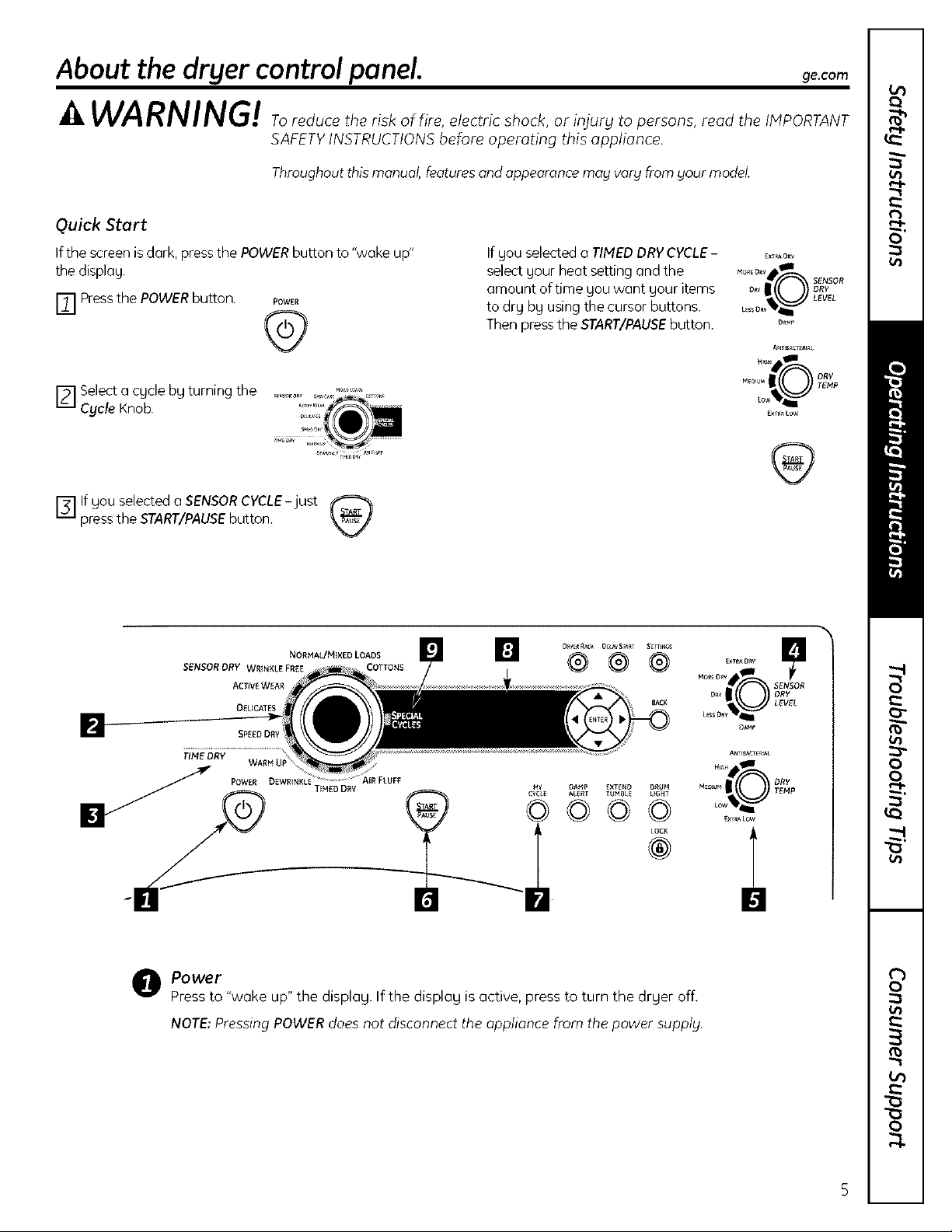
Quick Start
Ifthe screen is dark, press the POWER button to "wake up"
the display.
r_ Press the POWER button. POWER
@
F1 Select a cycle by turning the .......
Cycle Knob.
I'_'1If gou selected a SENSOR CYCLE-just
press the START/PAUSE button.
SENSOR ORY WRINKLE FR_E COTTONS
ACTIVEWEAR
DELtCATES
SP£_ODRY
NORHAL/MIXED LOADS
If you selected a TIMED DRY CYCLE- E=,,,o._
select your beat setting and the D_,
amount of time you want your items R
to dry by using the cursor buttons. L_,_o._i'_'_
Then press the START/PAUSE button. _"
A_TI_ACT_AL
..... II {()) TOE_p
_×I_A LoW
[]
® @
POWER D£WR{NKU
TIHEO DRY
AIR FLUFF
(
e Power
Pressto "wake up" the display. Ifthe display is active, press to turn the dryer off.
NOTE:Pressing POWERdoes not disconnect the appliance from the power supplg.
5
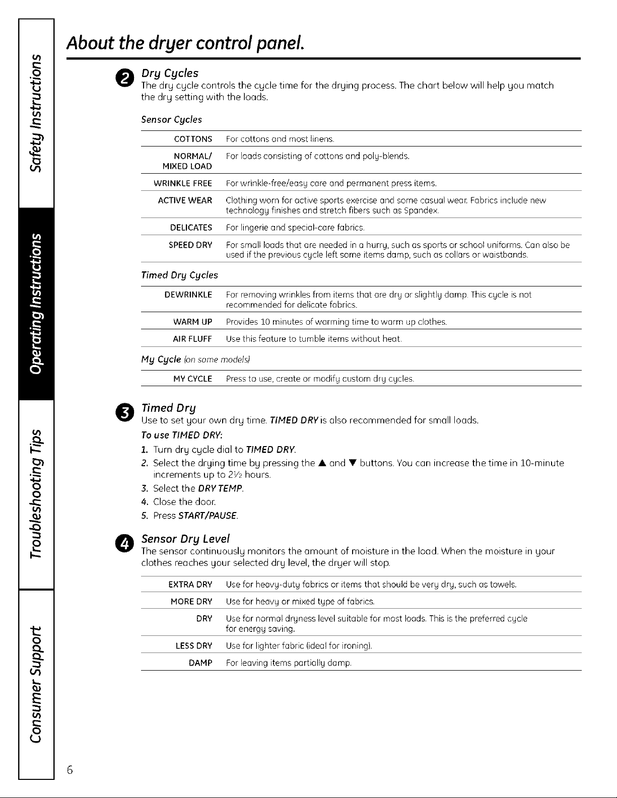
About the dryer control panel.
@Dry Cycles
The drg cycle controls the cycle time for the drying process. The chart below will help gou match
the drg setting with the loads.
Sensor Cycles
COTTONS For cottons end most linens.
NORMAL/ For loads consisting of cottons and poly-blends.
MIXED LOAD
WRINKLE FREE For wrinkle-free/easy core and permanent press items.
ACTIVEWEAR Clothing worn for active sports exercise and some casual weac Fabrics include new
technology finishes and stretch fibers such as Spondex.
DELICATES For lingerie and special-care fabrics.
SPEEDDRY For small loads that are needed in a hurry, such as sports or school uniforms. Can also be
used if the previous cycle left some items damp, such as collars or waistbands.
Timed Dry Cycles
DEWRINKLE For removing wrinkles from items that ore dry or slightly damp This cycle is not
WARM UP Provides 10 minutes of warming time to worm up clothes.
AIR FLUFF Use this feature to tumble items without heat.
My Cycle (on some models)
MY CYCLE Press to use,create or modify custom dry cycles.
Timed Dry
@
Use to set your own dry time. TIMED DRVis also recommended for small loads.
To use TIMED DRY:
1. Turn dry cycle dial to TIMED DRV.
2. Select the drying time bg pressing the • and • buttons. You can increase the time in lO-minute
increments up to 2Y_ hours.
& Select the DRY TEMP.
4. Close the doon
5. Press START/PAUSE.
O Sensor Dry Level
The sensor continuously monitors the amount of moisture in the load. When the moisture in your
recommended fol delicate fabrics.
clothes reaches your selected dry level, the dryer will stop.
EXTRADRY Use for heavy-duty fabrics or items that should be very dry, such as towels.
MORE DRY Use for heavy or mixed type of fabrics.
DRY Use for normal dryness level suitable for most loads. This is the preferred cycle
for energy saving.
LESSDRY Use for lighter fabric (ideal for ironing).
DAMP For leaving items partiollg damp.

Dry Tamp
You can change the temperature of gour drg cgcle.
ANTI-BACTERIAL This option may only be used with COTTONSor MIXED LOAD cycles. This option reduces
certain types of bacteria by 99.9%, including: Staphylococcus aureus, Pseudomonas
oeruginoso and Klebsiella pneumonioe* The anti-bacterial process occurs when high
heat is used during a portion of this drying cycle.
NOTE:Do not use this cycle on delicote fobrics.
* The Anti-Bacterial Cycle is Certified by NSFInternational {formerly National Sanitation
Foundation) to NSFProtocol P154 Sanitization Performance of Residential Clothes Dryers,
NSF PI oil/col 1'154
It.l:sitll_TIli_l(]lothe_l)_yel_
ge,com
HIGH
MEDIUM
LOW
EXTRALOW
For regular to heavy cottons.
For synthetics, blends and items labeled permanent press.
For delicates, synthetics and items labeled Tumble Dry Low
For lingerie and special-care fabrics.
START/PAUSE
Pressto start a dry cycle. If the dryer is running, press it once and it will pause the drgen
Pressit again to restart the dry cycle.
0
C_LE My Cycle ton some models)
(_Set up gour favorite combination of settings and save them here for one touch recall.
These custom settings can be set while a cgcle is in progress.
To store a MY CYCLE combination of settings:
1. Select your drying cycle.
2. Change DRY TEMP and SENSOR DRY LEVEL settings to fit your needs.
3. Select any drying OPTIONS you want.
4. Press and hold the MY CYCLE button for three seconds to store your selection. A beep will sound
and the button will light up.
To recall your stored MY CYCLE combination:
Press the MY CYCLE button before drying a load. The light around the button will light up when
MY CYCLE is selected.
To change your stored MY CYCLE combination:
Follow steps 1-4 in "To store a MY CYCLE combination of settings'.
Q
SpecialCycleStatusOR Est.CycleTime
DryerRackORTimedDry ORTimeto Dry
DelayTime LintFilterStatus DELAYTIME
Status Screen
"CLEAN LINT FILTER" (message)
This message stags onfor 15minutes after the cgcle finishes. This message is only a reminder.
Display
7
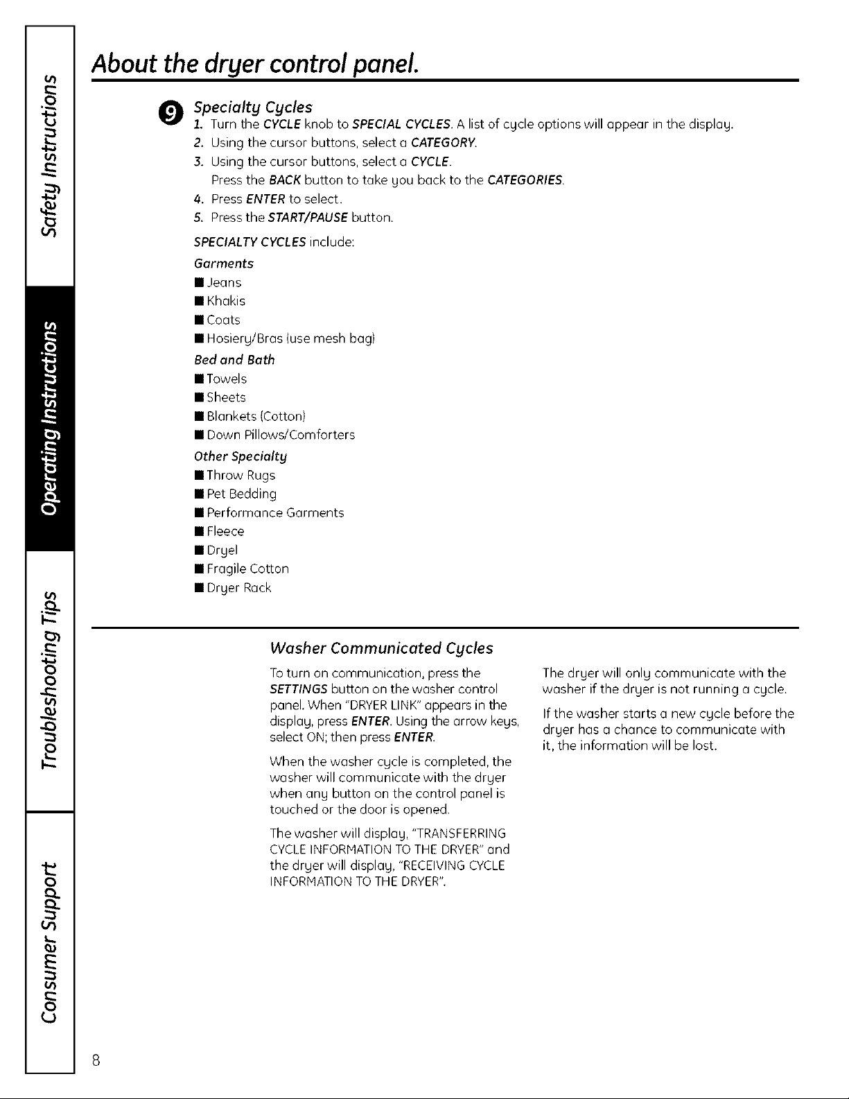
About the dryer controlpanel.
Specialty Cycles
1. Turn the CYCLEknob to SPECIALCYCLES.A list of cgcle options will appear in the displag.
2. Using the cursor buttons, select a CATEGORY.
3. Using the cursor buttons, select a CYCLE.
Pressthe BACKbutton to take gou back to the CATEGORIES.
4. PressENTERto select.
5. Press the START/PAUSEbutton.
SPECIALTYCYCLESinclude:
Garments
•Jeans
•Khakis
• Coats
• Hosierg/Bras (use mesh bag)
Bed and Bath
• Towels
• Sheets
• Blankets (Cotton)
• Down Pillows/Comforters
Other Specialty
• Throw Rugs
• Pet Bedding
• Performance Garments
• Fleece
1Dryel
• Fragile Cotton
• Dryer Rack
Washer Communicated Cycles
To turn on communication, press the
SETTINGS button on the washer control
panel. When "DRYER LINK" appears in the
displag, press ENTER. Using the arrow kegs,
select ON; then press ENTER.
When the washer cgcle is completed, the
washer will communicate with the drger
when ang button on the control panel is
touched or the door is opened.
The washer will displag, "TRANSFERRING
CYCLE INFORMATION TOTHE DRYER" and
the drger will display, "RECEIVING CYCLE
INFORHATION TO THE DRYER".
The drger will onlg communicate with the
washer if the drger is not running a cgcle.
If the washer starts a new cgcle before the
drger has a chance to communicate with
it, the information will be lost.
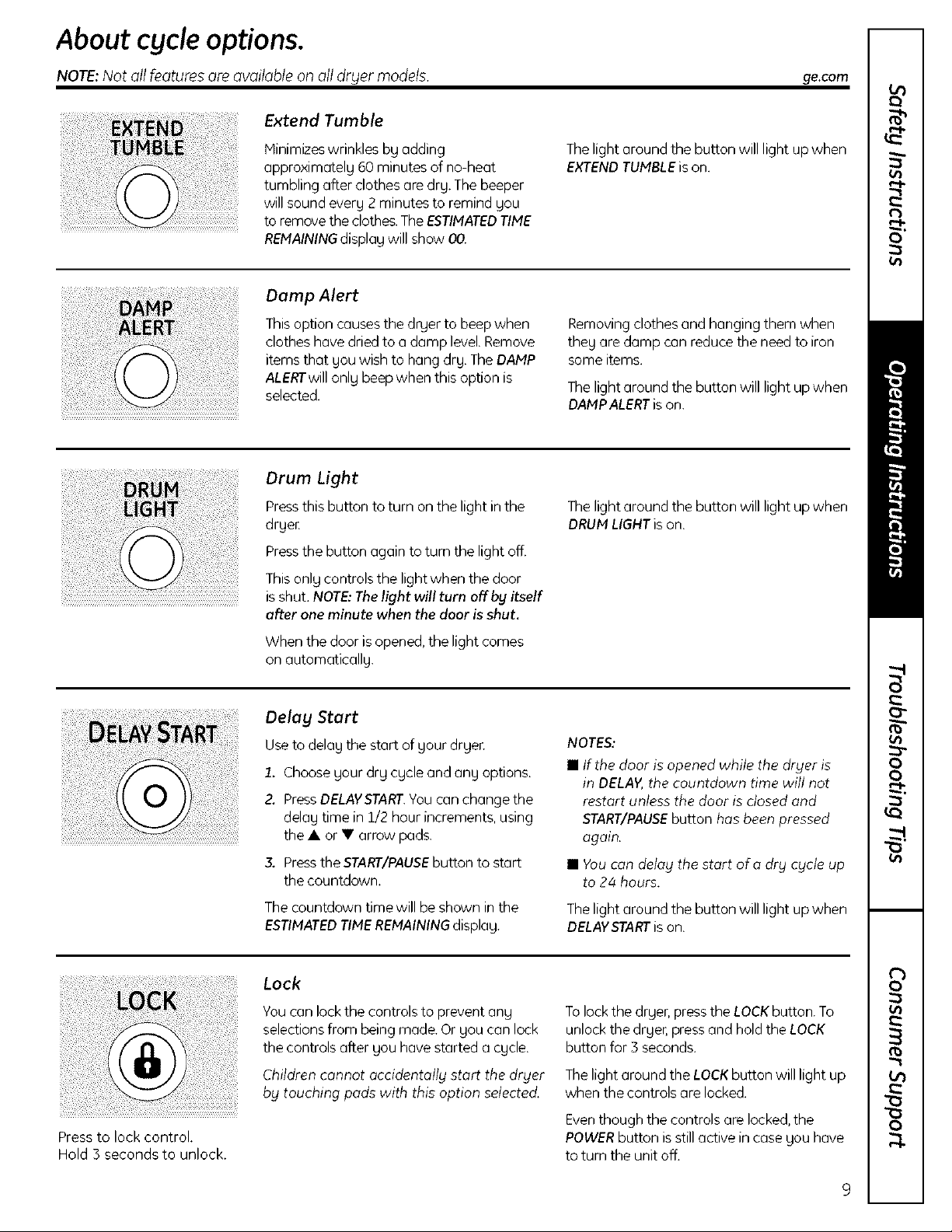
About cycleoptions.
NOTE:Not all features ore available on oil dr_lermodels.
Extend Tumble
Minimizeswrinkles bg adding
opproximatelg 60 minutes of no-heat
tumbling after clothes are drg.The beeper
will sound everg 2 minutes to remind gou
to removethe clothes.TheESTIMATEDTIME
REMAININGdisplag will show 00.
Damp Alert
Thisoption causesthe drger to beepwhen
clotheshave dried to o damp level.Remove
items that gou wish to hang drg.TheDAMP
ALERTwill onlg beep when this option is
selected.
Drum Light
Pressthis button to turn onthe light in the
drge_
Pressthe button again to turn the light off.
ge.com
Thelight around the button will light up when
EXTENDTUMBLEis on.
Removingclothes and hanging them when
theg are damp con reduce the need to iron
some items.
Thelight around the button will light up when
DAMPALERTison.
Thelight around the button will light up when
DRUMLIGHTison.
Thisonly controls the lightwhen the door
isshut. NOTE:Thelightwill turn offby itself
after one minute when the door isshut.
When the door is opened,the light comes
on automaticallg.
Delag Start
Useto delog the start of gour drger.
1. Choosegout drg cgcleand ang options.
Z PressDELAYSTART.Youcan change the
delag time in 1/2 hour increments, using
the • or • arrow pads.
3. Pressthe START/PAUSEbutton to start
the countdown.
Thecountdown timewill be shown in the
ESTIMATEDTIMEREMAININGdisplag.
Lock
Youcan lock the controls to prevent ong
selectionsfrom beingmade. Or gou can lock
the controls after gou have started a cgcle.
NOTES:
• If the door is opened while the dryer is
in DELAY,the countdown time will not
restart unless the door is closed and
START/PAUSEbutton has been pressed
again.
• Youcan delag the start ofa drg cgc/e up
to 24 hours.
Thelight around the button will light up when
DELAYSTARTison.
Tolockthe drger, pressthe LOCKbutton. To
unlock the drger, pressand hold the LOCK
button for 3 seconds.
Press to lock control.
Hold 3 seconds to unlock.
Children cannot occidentollg start the drger
bg touching pods with this option selectecL
Thelight around the LOCKbutton will light up
when the controls are locked.
Even though the controls are locked, the
POWER button is still active in case gou have
to turn the unit off.
About cgcleoptions.
NOTE:Not all features are available on all dr_ler models.
LSS55SS< LS(()(( ¸
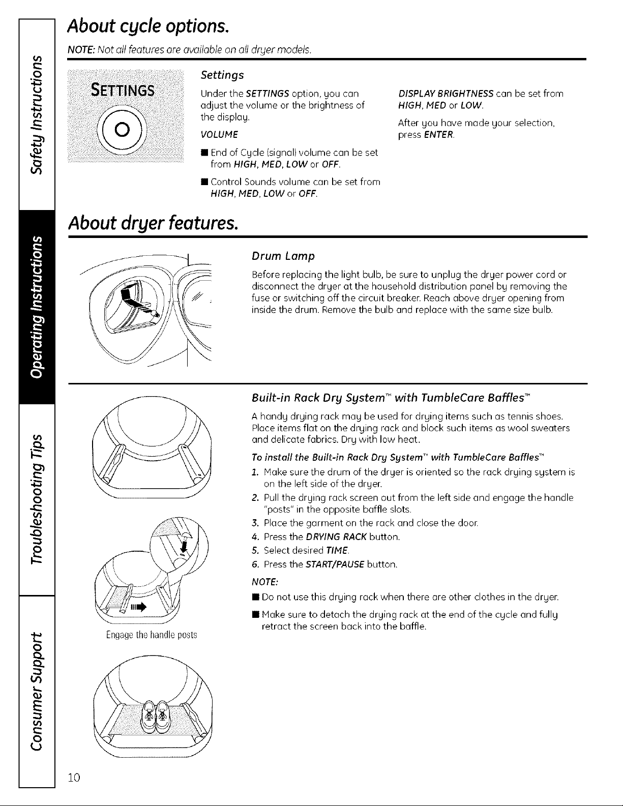
Settings
Under the SETTINGSoption, gou can
adjust the volume or the brightness of
the displag.
VOLUME
• End of Cgcle (signal)volume can be set
from HIGH, IVIED,LOW or OFF.
• Control Sounds volume can be set from
HIGH, MED, LOW or OFF.
About dryer features.
DISPLAY BRIGHTNESS can be set from
HIGH, IVIED or LOW.
After gou have made gour selection,
press ENTER.
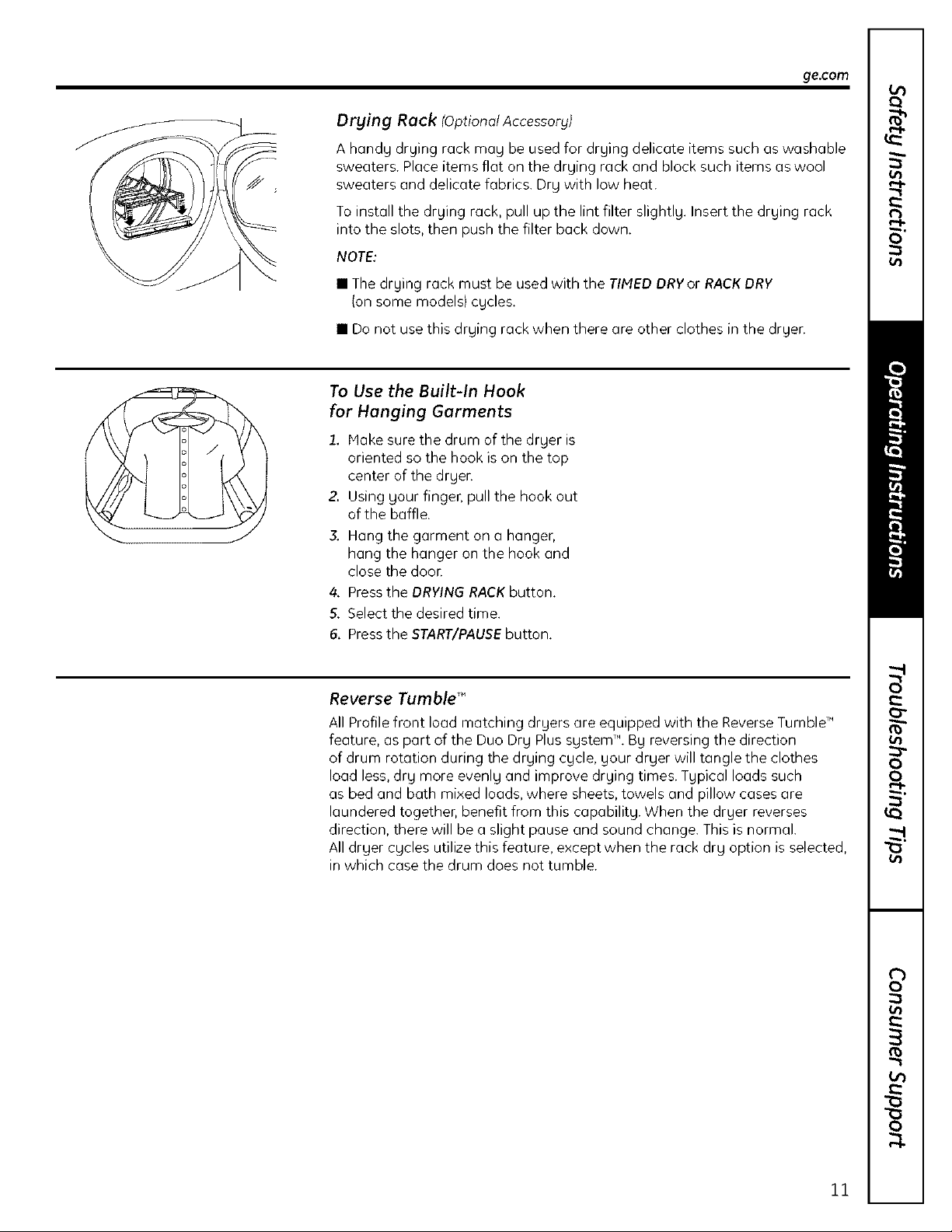
Drum Lamp
Before replacing the light bulb, be sure to unplug the drger power cord or
disconnect the drger at the household distribution panel bg removing the
fuse or switching off the circuit breaker. Reach above drger opening from
inside the drum. Remove the bulb and replace with the same size bulb.
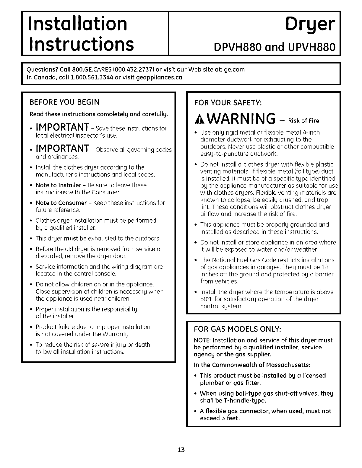
Engagethehandleposts
Built-in Rack Dry System T"with TumbleCare Baffles"
A handg drging rack mag be used for drging items such as tennis shoes.
Placeitems flat on the drging rack and block such items aswool sweaters
and delicate fabrics. Drg with low heat.
To install the Built-in Rack Dry SystemT"with TumbteCare Baffles_"
1. Hake sure the drum of the drger is oriented so the rack drging sgstem is
on the left side of the drger.
2. Pull the drging rack screen out from the left side and engage the handle
"posts" in the opposite baffle slots.
3. Place the garment on the rack and close the door.
4. Press the DRYING RACKbutton.
5. Select desired TIME.
6. Press the START/PAUSEbutton.
NOTE:
• Do not use this drging rack when there are other clothes in the drger.
• Make sure to detach the drging rack at the end of the cgcle and fullg
retract the screen back into the baffle.
10
ge,com
Drying Rack (Optional Accessory)
A handg drging rack mag be used for drging delicate items such aswashable
sweaters. Place items flat on the drging rack and block such items as wool
sweaters and delicate fabrics. Drg with low heat.
Toinstall the drging rack, pull up the lint filter slightlg. Insert the drging rack
into the slots, then push the filter back down.
NOTE:
• The drging rack must be used with the TINED DRYor RACKDRY
(on some models} cgcles.
• Do not use this drging rack when there are other clothes in the drgen
To Use the Built-In Hook
for Hanging Garments
1. Hake sure the drum of the drger is
oriented so the hook is on the top
center of the drger.
2. Using gour finger, pull the hook out
of the baffle.
J
3. Hang the garment on a hanger,
hang the hanger on the hook and
close the door.
4. Press the DRYING RACK button.
5. Select the desired time.
6. Press the START/PAUSE button.
Reverse Tumble T"
All Profile front load matching drgers are equipped with the Reverse TumbleTM
feature, as part of the Duo Drg PlussgstemTM. Bgreversing the direction
of drum rotation during the drging cgcle, gour drger will tangle the clothes
load less, drg more evenlg and improve drging times. Tgpical loads such
as bed and bath mixed loads, where sheets, towels and pillow cases are
laundered together, benefit from this capabilitg. When the drger reverses
direction, there will be a slight pause and sound change. This is normal.
All drger cgcles utilize this feature, except when the rack drg option is selected,
in which case the drum does nat tumble.
11

Using the dryer.
Alwags follow fabric manufacturer's care label when laundering.
Sorting and Loading Hints
Asageneral rule, if clothesare sorted
properlg for the washer,theg are sorted
properlg for the drger.Trg also to sort items
according to size.Forexample, do not drg
a sheet with socksor other small items.
Do not add fabric softener sheets once
the load has become warm. They may
cause fabric softener stains. Bounce®
Fabric Conditioner Dryer Sheets have
been approved for use inthis drger when
used in accordance with the manufacturer's
instructions.
Seebelow for lintfilter cleaning instructions.
Donot overload. Thiswastes energg and
causeswrinkling.
Donot drg the following items: fiberglass
items,woolens, rubber-coated items,plastics,
items with plastic trim and foam-filled items.
Fabric Care Labels
Belowarefabric care label "sgmbols" that
affect the clothing gou will be laundering.
Dry Labels
,o ,or-lvFo-1 FO-1
dr. Do.ord_v
,eo, @ ® ® •
setting
Dly Norn/a] Peln/anent PEess/ Gentle/ Do not tun/hie dry {use_Jwith
High Medium Low Noheat/oil
wEh_kleIesJstar_t delicate do not wash)
12
S ecia,
instructions
Lithedig/ Drip dly
hang to dly
Care and Cleaning of the Drger
Drger Interior and Duct: The interior of
the appliance and exhaust duct should be
cleaned once a gear bg qualified service
personnel.
The Exterior: Wipe or dust ang spills or
washing compounds with a damp cloth.
Drger control panel and finishes mag be
damaged bg some laundrg pretreatment
soil and stain remover products. Applg
these products awag from the drgen The
fabric mag then be washed and dried
normallg. Damage to gour drger caused
bg these products is not covered bg gour
warrantg.
Do not touch the surface or the displag
with sharp objects.
The Lint Filter: Clean the lint filter before
each use. Remove bg pulling straight up.
Run gour fingers across the filter. A waxg
buildup mag form on the lint filter from
using drger-added fabric softener sheets.
To remove this buildup, wash the lint
screen in warm, soapg water. Drg
Fq
DEyflat
thoroughlg and replace. Do not operate
the drger without the lint filter in place.
Vacuum the lint from the drger lint
filter if gou notice a change in drger
performance.
Stainless Steel: To clean stainless steel
surfaces, use a damp cloth with a mild,
nonabrasive cleaner suitable for stainless
steel surfaces. Remove the cleaner
residue, and then drg with a clean cloth.
The stainless steel used to make
the drger drum provides the highest
reliabilitg available in a GEdrger. If
the drger drum should be scratched or
dented during normal use, the drum
will not rust or corrode. These surface
blemishes will not affect the function
or durabilitg of the drum.
The Exhaust Hood: Check with a mirror
that the inside flaps of the hood move
freelg when operating. Hake sure that
there is no wildlife (birds, insects, etc.}
nesting inside the duct or hood.
hi the shade
Installation
Drger
Instructions
In Canada, coil 2.800.561.3344 or visit geopplionces.co
I Questions? Coil 800.GE.CARES (800.432.2737) or visit our Web site at: ge.com
BEFORE YOU BEGIN
Read these instructions completelg and corefullg.
FOR YOUR SAFETY:
DPVH880 and UPVH880
a,WARNING -- Risk of Fire
• IMPORTANT- savetheseinstructionsfor
local electrical inspector's use.
•IM PORTANT-Observeallgoverningcodes
and ordinances.
• Install the clothes drger according to the
manufacturer's instructions and local codes.
• Note to Installer - Be sure to leave these
instructions with the Consumen
• Note to Consumer - Keep these instructions for
future reference.
• Clothes drger installation must be performed
bg a qualified installer.
• This drger must be exhausted to the outdoors.
• Before the old drger is removed from service or
discarded, remove the drger door.
• Service information and the wiring diagram are
located in the control console.
• Do not allow children on or in the appliance.
Close supervision of children is necessarg when
the appliance is used near children.
• Proper installation is the responsibilitg
of the installer.
• Use onlg rigid metal or flexible metal 4-inch
diameter ductwork for exhausting to the
outdoors. Never use plastic or other combustible
easg-to-puncture ductwork.
• Do not install a clothes drger with flexible plastic
venting materials. If flexible metal (foil tgpe)duct
is installed, it must be of a specific tgpe identified
bg the appliance manufacturer as suitable for use
with clothes drgers. Flexible venting materials are
known to collapse, be easilg crushed, and trap
lint. These conditions will obstruct clothes drger
airflow and increase the risk of fire.
• This appliance must be properlg grounded and
installed as described in these instructions.
• Do not install or store appliance in on area where
it will be exposed to water and/or weather.
• The Notional Fuel Gas Code restricts installations
of gas appliances in garages. Theg must be 18
inches off the ground and protected bg a barrier
from vehicles.
• Install the drger where the temperature is above
SO°Ffor satisfactorg operation of the drger
control sgstem.
• Product failure due to improper installation
is not covered under the Warrantg.
• To reduce the risk of severe injurg or death,
follow all installation instructions.
FOR GAS MODELS ONLY:
NOTE: Installation and service of this drger must
be performed bg o qualified installer, service
ogencg or the gas supplier.
In the Commonwealth of Massachusetts:
• This product must be installed bg o licensed
plumber or gas fitter.
• When using boll-tgpe gas shut-offvolves, theg
shall be T-hondle-tgpe.
• A flexible gas connector, when used, must not
exceed 3 feet.
13
Installation Instructions
UNPACKING YOUR DRYER
Tilt the dryer sideways and remove the foam
shipping pads by pulling at the sides and breaking
them away from the dryer legs. Be sure to remove
all of the foam pieces around the legs.
Remove the bag containing the literature and serial
cable.
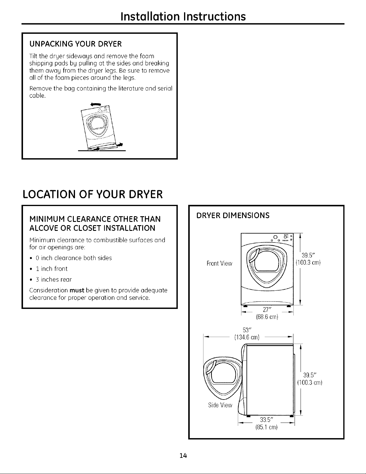
LOCATION OF YOUR DRYER
MINIMUM CLEARANCE OTHER THAN
ALCOVE OR CLOSET INSTALLATION
Hinimum clearance to combustible surfaces and
for air openings are:
• 0 inch clearance both sides
• linch front
• 3 inches rear
Consideration must be given to provide adequate
clearance for proper operation and service.
DRYER DIMENSIONS
FrontView
... 27"
(68.6cm)
53"
(134.6cm) "-
t
39.5"
(100.3cm)
14
39.5"
(100.3cm)
Side View
33.5"
(85.1 cm)
Installation Instructions
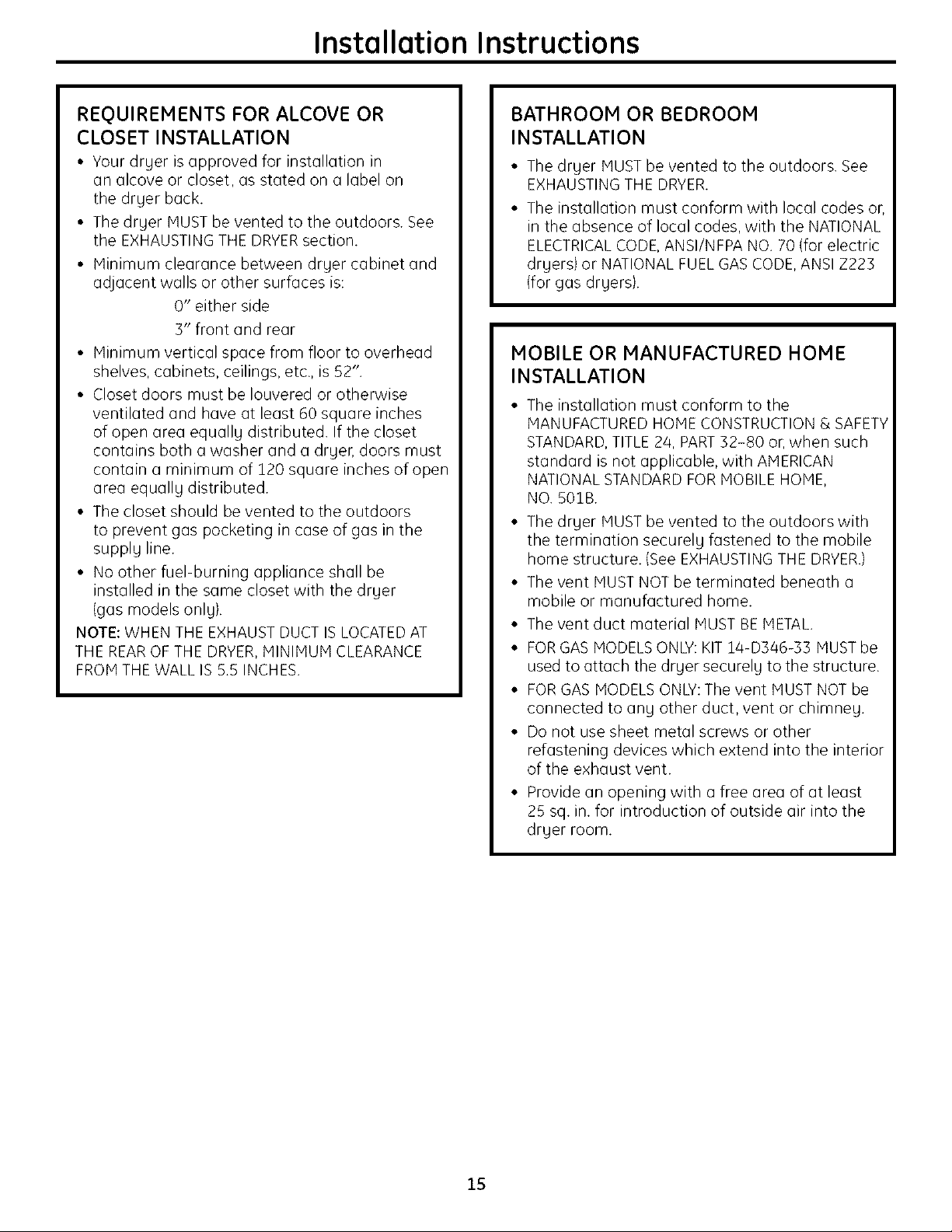
REQUIREMENTS FOR ALCOVE OR
CLOSET INSTALLATION
• Your drger is approved for installation in
an alcove or closet, as stated on a label on
the druer back.
• The drger MUST be vented to the outdoors. See
the EXHAUSTING THE DRYERsection.
• Minimum clearance between druer cabinet and
adjacent walls or other surfaces is:
0" either side
3" front and rear
• Minimum vertical space from floor to overhead
shelves, cabinets, ceilings, etc., is 52".
• Closet doors must be Iouvered or otherwise
ventilated and have at least 60 square inches
of open area equall U distributed. If the closet
contains both a washer and a drger, doors must
contain a minimum of 120 square inches of open
area equall Udistributed.
• The closet should be vented to the outdoors
to prevent gas pocketing in case of gas in the
suppl U line.
• No other fuel-burning appliance shall be
installed in the same closet with the dryer
(gas models onlg}.
NOTE: WHEN THE EXHAUST DUCT IS LOCATEDAT
THE REAROF THE DRYER, MINIMUM CLEARANCE
FROM THE WALL IS 5.5 INCHES.
BATHROOM OR BEDROOM
INSTALLATION
• The drger MUST be vented to the outdoors. See
EXHAUSTING THE DRYER.
• The installation must conform with local codes or,
in the absence of local codes, with the NATIONAL
ELECTRICALCODE, ANSI/NFPA NO. 70 (for electric
drgers) or NATIONAL FUEL GAS CODE, ANSI Z223
(for gas drgers}.
MOBILE OR MANUFACTURED HOME
INSTALLATION
• The installation must conform to the
MANUFACTURED HOlE CONSTRUCTION & SAFETY
STANDARD, TITLE 2/4, PART32-80 or, when such
standard is not applicable, with AMERICAN
NATIONAL STANDARD FOR MOBILE HOME,
NO. S01B.
• The druer MUST be vented to the outdoors with
the termination securel Ufastened to the mobile
home structure. (See EXHAUSTING THE DRYER.)
• The vent MUST NOT be terminated beneath a
mobile or manufactured home.
• The vent duct material MUST BE METAL
• FORGAS MODELS ONLY:KIT 14-D346-35 MUST be
used to attach the druer securel U to the structure.
• FORGAS MODELS ONLY:The vent MUST NOT be
connected to an U other duct, vent or chimney.
• Do not use sheet metal screws or other
refastening devices which extend into the interior
of the exhaust vent.
• Provide an opening with a free area of at least
25 sq. in. for introduction of outside air into the
druer room.
15
Installation Instructions
CONNECTING A GAS DRYER(skip for electric drgers)
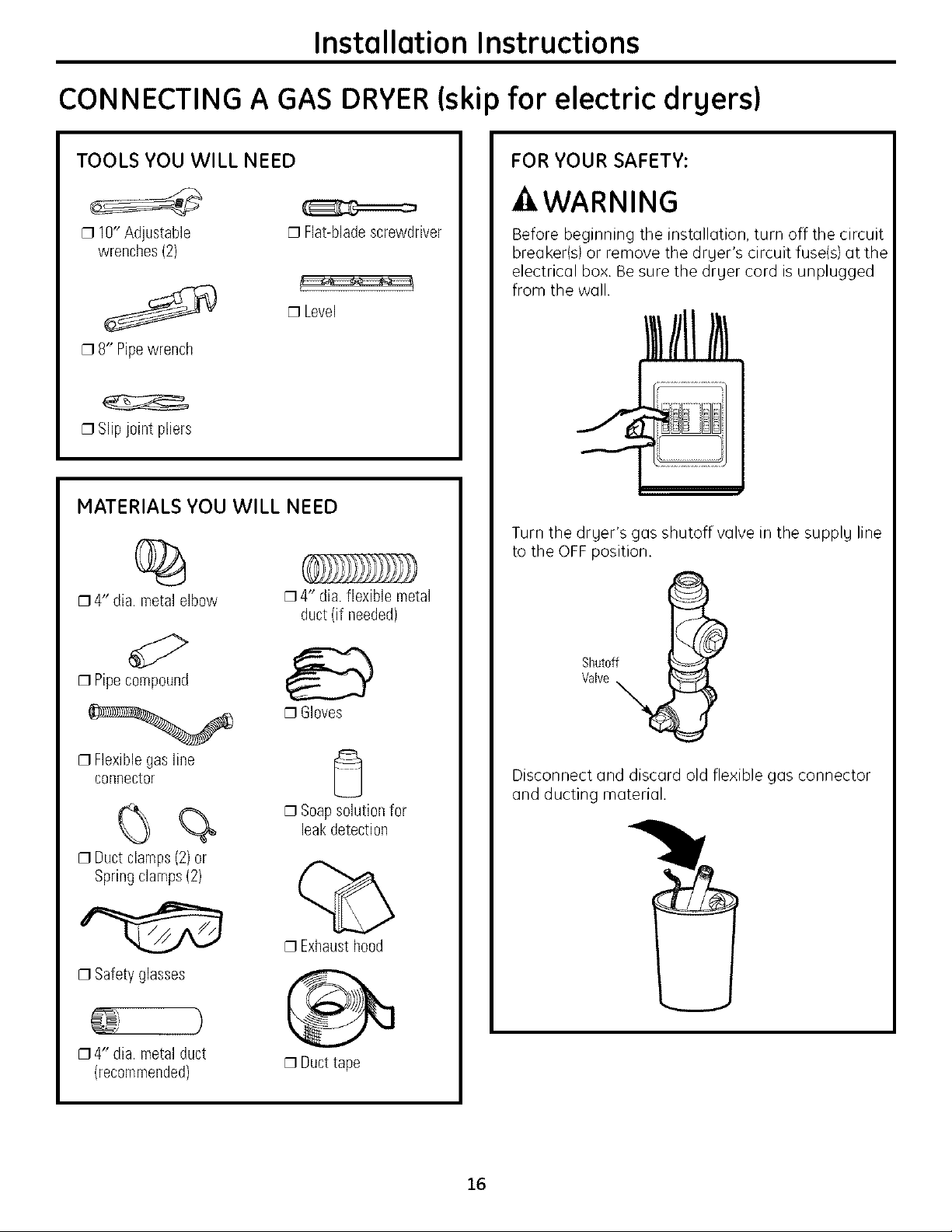
TOOLS YOU WILL NEED
[] 10" Adjustable
wrenches (2)
[] 8" Pipewrench
[] Slip joint pliers
MATERIALS YOU WILL NEED
[] Flat-bladescrewdriver
$.
[] Level
%
[] 4" dia. metal elbow
[] 4" dia. flexible metal
duct (if needed)
FOR YOUR SAFETY:
-_WARNING
Before beginning the installation, turn off the circuit
breaker(a) or remove the drger'a circuit fuse(s) at the
electrical box. Be sure the drger cord is unplugged
from the wall.
Turn the drger's gas shutoff valve in the supplg line
to the OFF position.
d:>
[] Pipecompound
[] Flexible gas line
connector
%
[] Duct clamps (2) or
Spring clamps(2)
[]Safety glasses
[] 4" dia. metal duct
(recommended)
Valve
Shutoff i
[]Gloves
Disconnect and discard old flexible gas connector
and ducting material.
[] Soap solution for
leakdetection
[]Exhaust hood
)
[] Duct tape
16
Installation Instructions
GAS REQUIREMENTS
-&WARNING
• Installation must conform to local codes
and ordinances, or in their absence, the
NATIONAL FUEL GAS CODE, ANSI Z223.
• This gas dryer is equipped with a Valve and
Burner Assembly for use only with natural gas.
Using conversion kit la-A048, your local service
organization can convert this dryer for use with
propane {LP) gas. ALL CONVERSIONS MUST BE
MADE BY PROPERLYTRAINED AND QUALIFIED
PERSONNEL AND IN ACCORDANCE WITH LOCAL
CODES AND ORDINANCE REQUIREMENTS.
• The dryer must be disconnected from the gas
supply piping system during any pressure testing
of that system at a test pressure in excess of
O.SPSI(3.4KPa).
• The dryer must be isolated from the gas supply
piping system by closing the equipment shut-off
valve during any pressure testing of the gas
supply piping of test pressure equal to or less
than 0.5 PSI(3.4KPa).
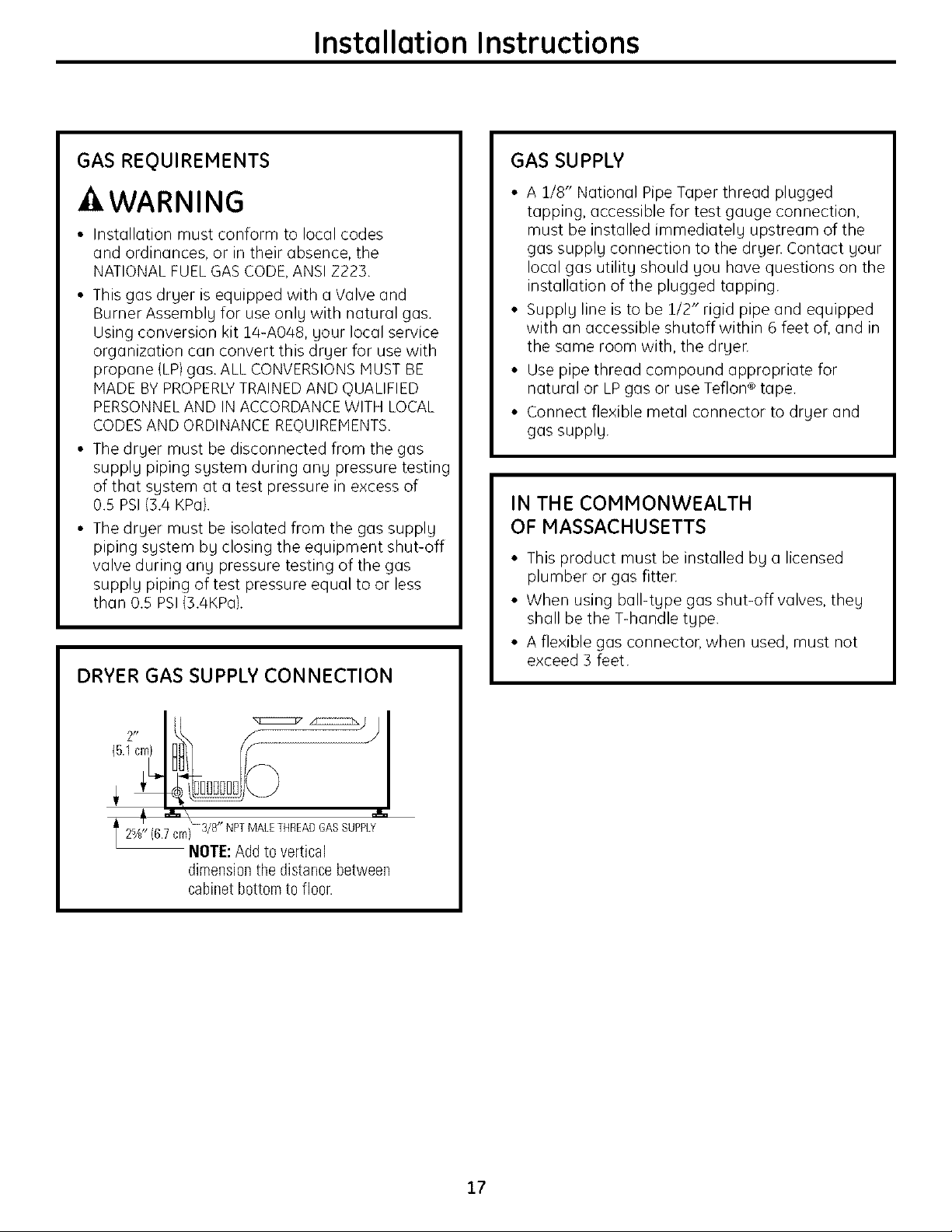
DRYER GAS SUPPLY CONNECTION
GAS SUPPLY
• A 1/8" National Pipe Taper thread plugged
tapping, accessible for test gauge connection,
must be installed immediately upstream of the
gas supply connection to the dryer. Contact your
local gas utility should you have questions on the
installation of the plugged tapping.
• Supply line is to be 1/2" rigid pipe and equipped
with an accessible shutoff within 6 feet of, and in
the same room with, the dryer.
• Use pipe thread compound appropriate for
natural or LP gas or use Teflon ®tape.
• Connect flexible metal connector to dryer and
gas supply.
IN THE COMMONWEALTH
OF MASSACHUSETTS
• This product must be installed by a licensed
plumber or gas fitten
• When using ball-type gas shut-off valves, they
shall be the T-handle type.
• A flexible gas connector, when used, must not
exceed 3 feet.
(6.7
t2%" cm} 3/8" NPTMALETHREADGASSUPPLY
NOTE: Add to vertical
dimension the distance between
cabinet bottom to floor.
17
Installation Instructions
CONNECTING A GAS DRYER(cont.)
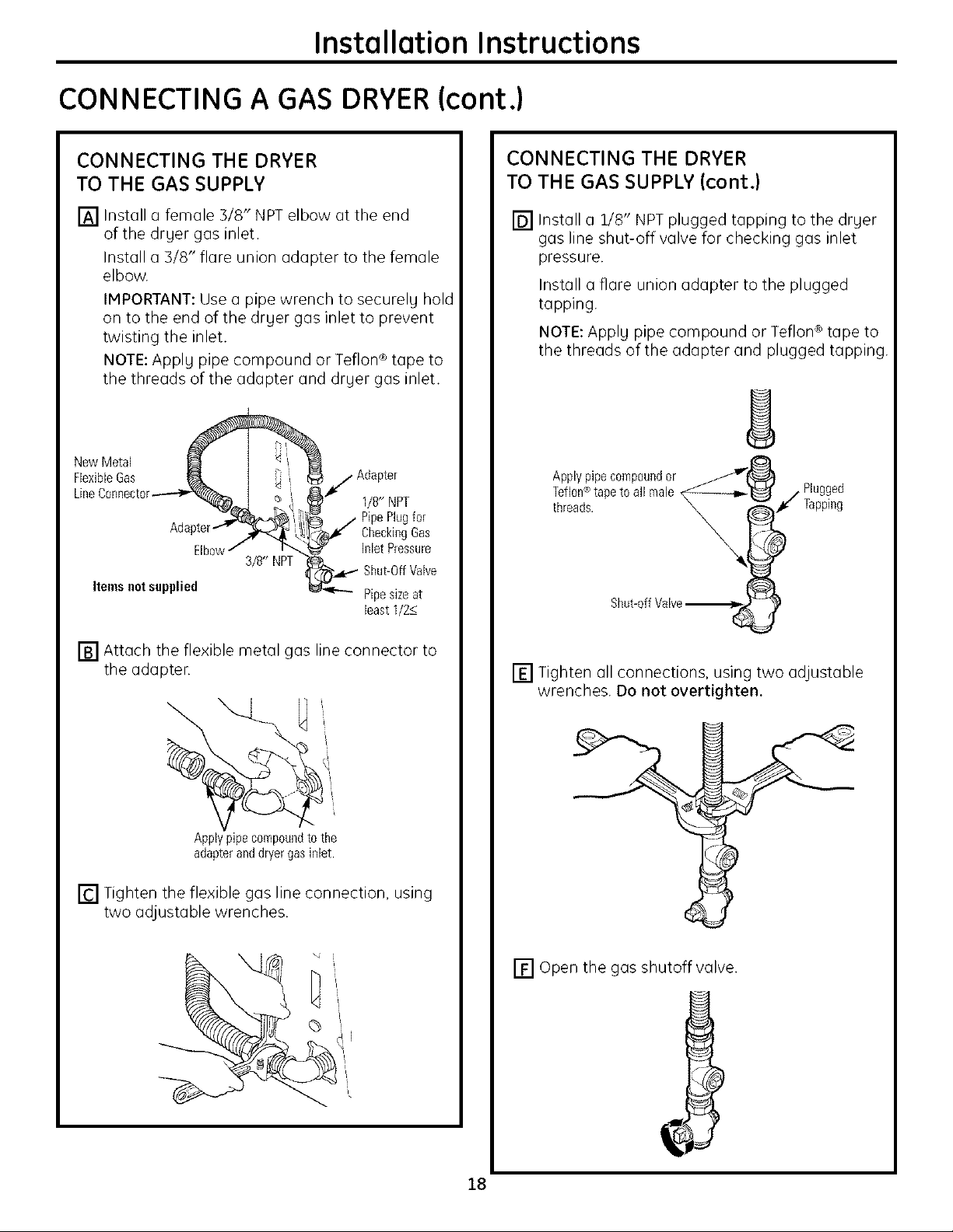
CONNECTING THE DRYER
TO THE GAS SUPPLY
[] Install a female 3/8" NPT elbow at the end
of the dryer gas inlet.
Install a 3/8" flare union ada )ter to the female
elbow.
IMPORTANT: Use a pipe wrench to securely hold
on to the end of the dryer gas inlet to prevent
twisting the inlet.
NOTE: Apply pipe compound or Teflon ® tape to
the threads of the adapter and dryer gas inlet.
New Metal
FlexibleGas _ t i_
LineConnector----I_-'_)_ t _ _
apter'_J_ _,
3/8" NPT
Items notsupplied
_/Adapter
_" 1/8" NPT
_ / PipePlugfor
lZ_i ¢" CheckiegGas
._ lelet Pressure
_ Shut-OffValve
Pipesizeat
least1/2<_
CONNECTING THE DRYER
TO THE GAS SUPPLY (cont.)
[] Install a 1/8" NPT plugged tapping to the dryer
gas line shut-off valve for checking gas inlet
pressure.
Install a flare union adapter to the plugged
tapping.
NOTE: Apply pipe compound or Teflon ® tape to
the threads of the adapter and plugged tapping.
Applypipe compoundor _J
Teflon®tapeto all male _--_U / Plugged
threads. _ I _ _" Tapping
Shut-offValve_-_
[] Attach the flexible metal gas line connector to
the adapter.
Applypipecompoundto the
adapteranddryergasinlet.
[] Tighten the flexible gas line connection, using
two adjustable wrenches.
[] Tighten all connections, using two adjustable
wrenches. Do not overtighten.
[] Open the gas shutoff valve.
18

Installation Instructions
TEST FOR LEAKS
-AWARNING - Neveruseon
open florae to test for gas leaks.
Check all connections for leaks with soapy solution
or equivalent.
Applg a soap solution. The leak test solution must
not contain ammonia, which could cause damage
to the brass fittings.
If leaks are found, close the valve, retighten the joint
and repeat the soap test.
OpenGas
ELECTRICAL REQUIREMENTS
FOR GAS DRYERS
This appliance must be supplied with J_20V,60Hz,
and connected to a properlg grounded branch
circuit, protected bg a 15- or 20-amp circuit
breaker or time-delag fuse.
If electrical supplg provided does not meet
the above specifications, it is recommended that
a licensed electrician install an approved outlet.
A WARNING - This dryer is equipped
with a three-prong {grounding) plug for your
protection against shock hazard and should be
plugged directl Uinto a properlg grounded three-
prong receptacle. Do not cut or remove the
grounding terminal from this plug.
f
ELECTRICAL CONNECTION
INFORMATION FOR GAS DRYERS
-AWARNING - Toreducetheriskof
fire, electricol shock ond personal injurg:
• Do not use an extension cord or an adapter plug
with this appliance.
• The drger must be electricallg grounded in
accordance with local codes and ordinances,
or in the absence of local codes, in accordance
with the NATIONAL ELECTRICALCODE, ANSI/NFPA
NO. 70.
Ensureproper • " "
ground exists
beforeuse.
If local codes permit, an external ground wire (not
provided), which meets local codes, mag be added
bg attaching to the green ground screw on the rear
of the drger, and to an alternate established ground.
Ensure proper ground exists before use.
Ground
Screw
I II II
19
Installation Instructions
CONNECTING AN ELECTRICDRYER(skip for gas drgers)
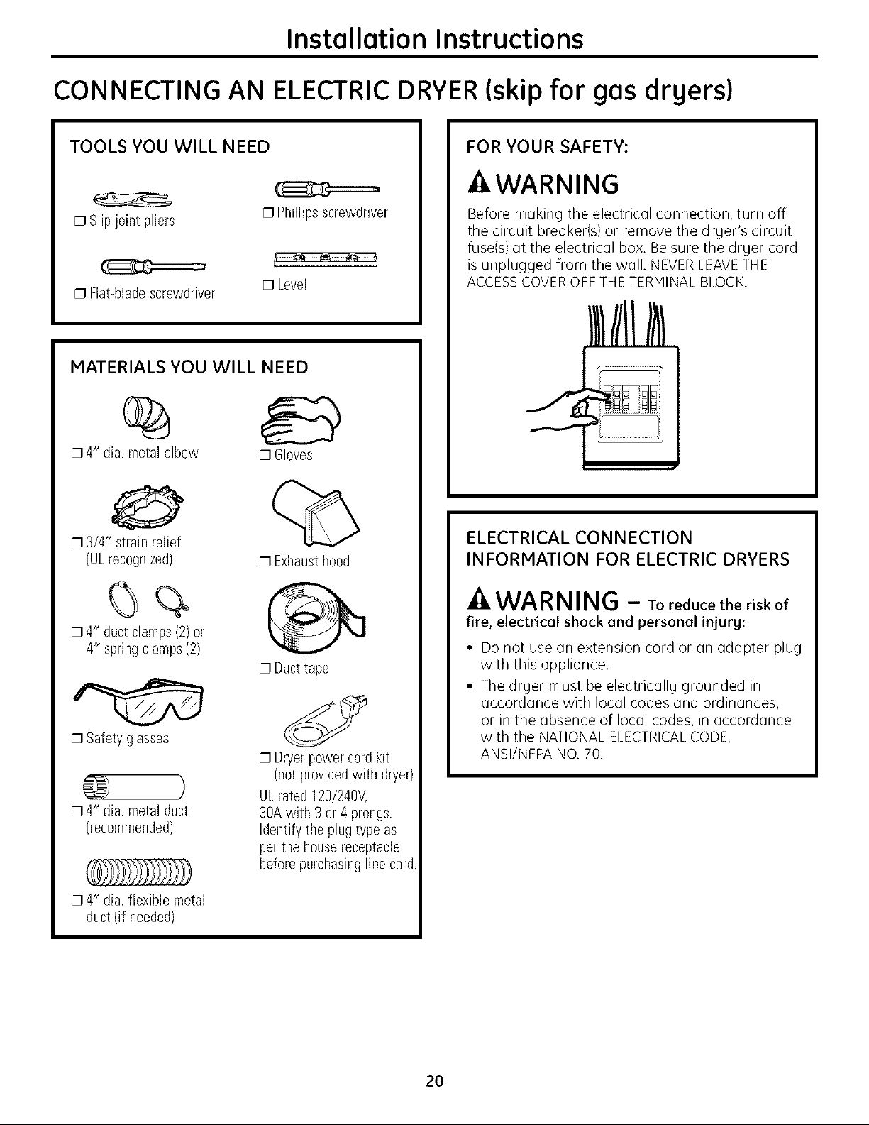
TOOLS YOU WILL NEED
[] Slip j0int pliers
[] Flat-blade screwdriver
[] Phillips screwdriver
[] Level
MATERIALS YOU WILL NEED
%
[] 4" dia. metal elbow [] Gloves
[] 3/4" strain relief
(ULrecognized)
[]Exhaust hood
FOR YOUR SAFETY:
-_WARNING
Before making the electrical connection, turn off
the circuit breaker(s) or remove the druer's circuit
fuse(s) at the electrical box. Be sure the druer cord
is unplugged from the wall. NEVER LEAVETHE
ACCESSCOVER OFF THE TERMINAL BLOCK.
ELECTRICAL CONNECTION
INFORMATION FOR ELECTRIC DRYERS
[] 4" duct clamps(2) or
4" spring clamps (2)
[]Safety glasses
[] 4" dia. metal duct
(recommended)
[] 4'* dia. flexible metal
duct (if needed)
[] Duct tape
[] Dryer power cord kit
(not provided with dryer)
ULrated 120/240V,
30A with 3 or 4 prongs.
Identify the plug type as
per the housereceptacle
before purchasing line cord.
-AWARNING - TO reduce the risk of
fire, electricel shock and personal injury:
• Do not use an extension cord or an adapter plug
with this appliance.
• The druer must be electricallu grounded in
accordance with local codes and ordinances,
or in the absence of local codes, in accordance
with the NATIONAL ELECTRICALCODE,
ANSI/NFPA NO. 70.
2O
Installation Instructions
ELECTRICAL REQUIREMENTS
FOR ELECTRIC DRYERS
This dryer must be connected to an individual
branch circuit, protected by the required time-
delay fuses or circuit breakers. A three- or four-
wire, single phase, 120/240V or 120/208V, 60Hz,
30-amp circuit is required.
If the electric supply does not meet the above
specifications, then call a licensed electrician.
GROUNDING INSTRUCTIONS
This dryer must be connected to a grounded metal,
permanent wiring system, or an equipment-
grounding conductor must be run with the circuit
conductors and connected to the equipment
grounding terminal on the appliance.
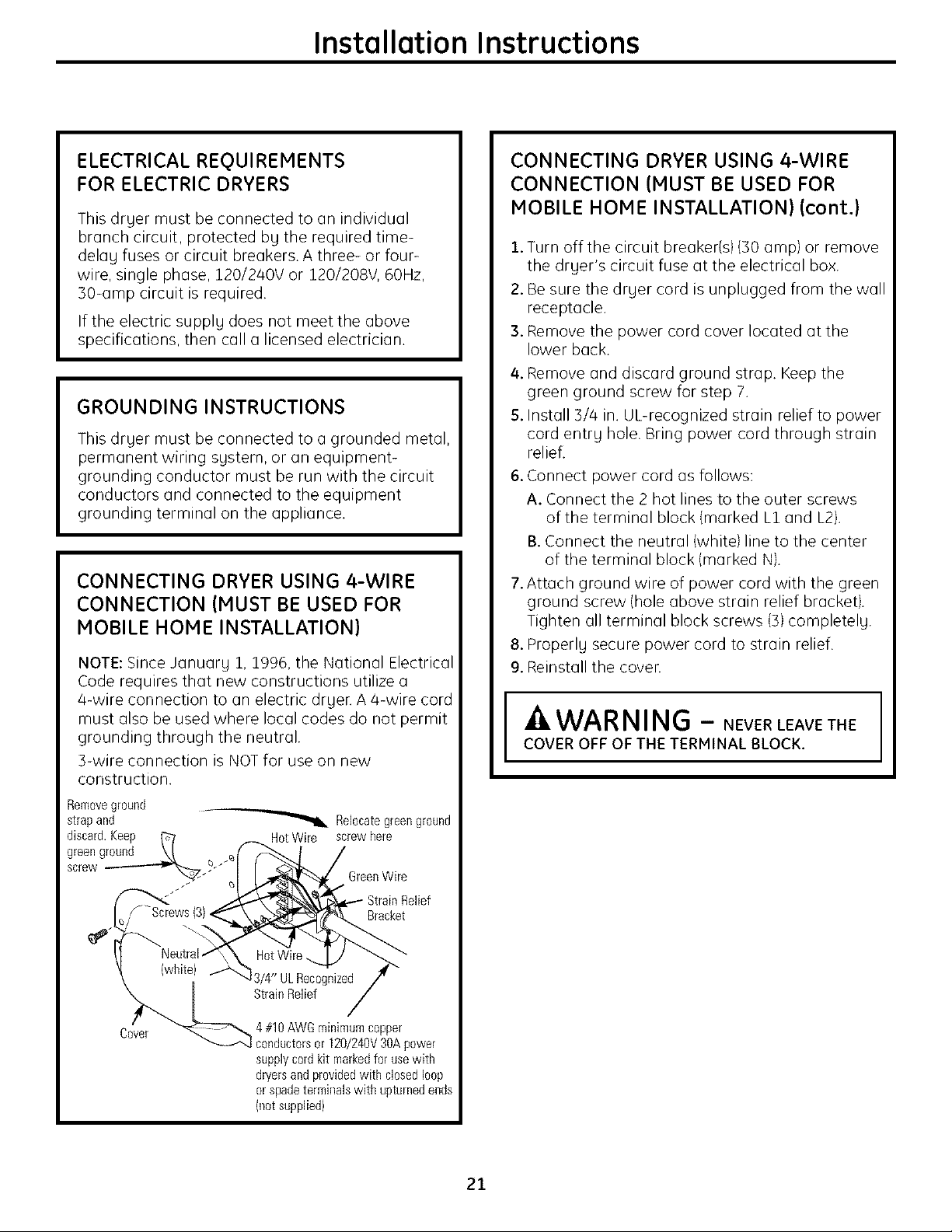
CONNECTING DRYER USING 4-WIRE
CONNECTION (MUST BE USED FOR
MOBILE HOME INSTALLATION)
NOTE: Since January 1, 1996, the National Electrical
Code requires that new constructions utilize a
4-wire connection to an electric dryer. A 4-wire cord
must also be used where local codes do not permit
grounding through the neutral.
3-wire connection is NOT for use on new
construction.
CONNECTING DRYER USING 4-WIRE
CONNECTION (MUST BE USED FOR
MOBILE HONE INSTALLATION) (cont.)
1.Turn off the circuit breaker(s)(30 amp) or remove
the dryer's circuit fuse at the electrical box.
2. Be sure the dryer cord is unplugged from the wall
receptacle.
3. Remove the power cord cover located at the
lower back.
4. Remove and discard ground strap. Keep the
green ground screw for step 7.
5. Install 3//4 in. UL-recognized strain relief to power
cord entry hole. Bring power cord through strain
reliefi
6. Connect power cord as follows:
A. Connect the 2 hot lines to the outer screws
of the terminal block (marked L1 and L2).
B. Connect the neutral (white)line to the center
of the terminal block (marked N).
7. Attach ground wire of power cord with the green
ground screw (hole above strain relief bracket).
Tighten all terminal block screws (3)completely.
8. Properly secure power cord to strain relief.
9. Reinstall the coven
-AWAR NING - NEVERLEAVETHE
COVER OFF OF THE TERMINAL BLOCK.
Removeground
strapand _ Relocategreenground
discard.Keep E1 HotWire screwhere
green groued \[ ._ _"'_-- i /
_'" _\'_-[:¢_._1.I StrainRelief
/ Screws(3)_ \. _i'_l_'_y_k_ Bracket
,] NeutralS\ HotWire,,_ IJ _'_"
Cover _'_----_,_ 4 #10AWGminimumcopper
o -_---_-J conductorsor 120/240V30Apower
supplycordkit markedforusewith
dryersandprovidedwith closedloop
or spadeterminalswith upturnedends
(notsupplied)
21
Installation Instructions
CONNECTING AN ELECTRICDRYER(cont.)
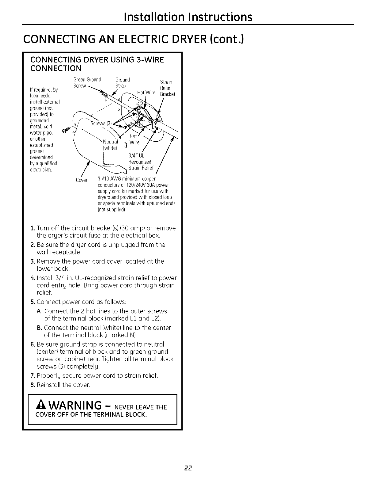
CONNECTING DRYER USING 3-WIRE
CONNECTION
GreenGround
if required,by
localcode,
installexternal
ground(not
provided)to
grounded
metal,cold
water pipe,
or other
established
ground
determined
byaqualified
electrician,
Cover 3 #10AWGminimumcopper
1.Turn off the circuit breaker(s) (30 amp) or remove
the drger's circuit fuse at the electrical box.
2. Be sure the drger cord is unplugged from the
wall receptacle.
3. Remove the power cord cover located at the
lower back.
4. Install 3/4 in. UL-recognized strain relief to power
cord entrg hole. Bring power cord through strain
relief.
5. Connect power cord as follows:
A. Connect the 2 hot lines to the outer screws
of the terminal block (marked L1 and L2).
B. Connect the neutral (white) line to the center
of the terminal block {marked N).
6. Be sure ground strap is connected to neutral
(center) terminal of block and to green ground
screw on cabinet rean Tighten all terminal block
screws (3) completelg.
7. Properlg secure power cord to strain relief.
8. Reinstall the cover.
Ground Strain
Strap Relief
HotWire Bracket
,Neutral Wire
(white) _]
3/4" UL
Recognized
StrainRelief
conductorsor 120/240V30Apower
supplycordkit markedforusewith
dryersandprovidedwith closedloop
or spadeterminalswith upturnedends
(notsupplied)
COVER OFF OF THE TERMINAL BLOCK.
kWARNING - NEVER LEAVETHE I
22
Installation Instructions
EXHAUSTING THE DRYER
-A WARNING - Toreducethe
risk of fire or personal injury:
• This dryer must be exhausted to the outdoors.
• Use only metal duct.
• Do not terminate exhaust into a chimney, any
gas vent, under an enclosed floor, in a crawl
space, wall, ceiling, into an attic or other
concealed space of a building. The accumulated
lint could create a fire hazard.
• Provide an access for inspection and cleaning
of the exhaust system, especially at turns.
Inspect and clean at least once a gear.
• Never terminate the exhaust into a common
duct with a kitchen exhaust. A combination
of lint and grease could create a fire hazard.
• Do not obstruct incoming or exhausted air.
• This drger comes ready for rear exhausting.
If space is limited, use the instructions
on pages 28-31 to exhaust directly
from the sides or bottom of the cabinet.
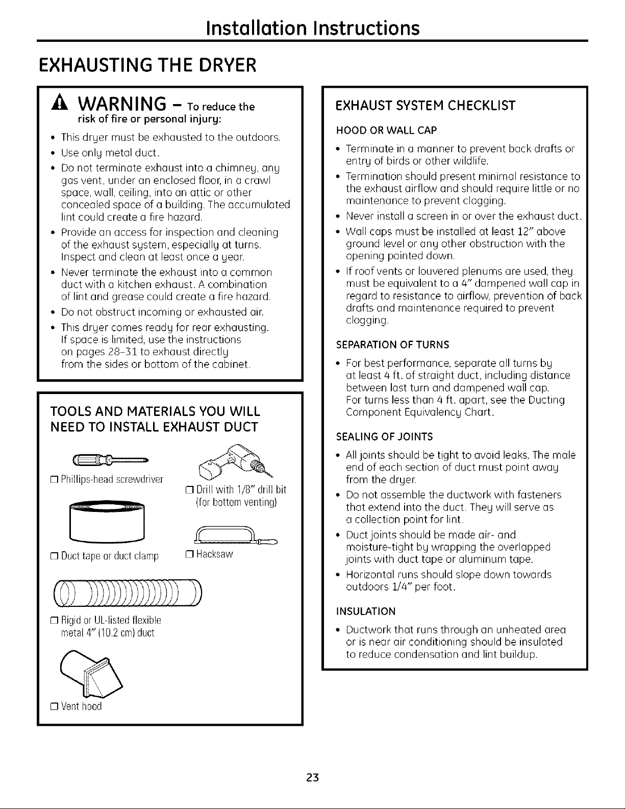
TOOLS AND MATERIALS YOU WILL
NEED TO INSTALL EXHAUST DUCT
EXHAUST SYSTEM CHECKLIST
HOOD OR WALL CAP
• Terminate in a manner to prevent back drafts or
entry of birds or other wildlife.
• Termination should present minimal resistance to
the exhaust airflow and should require little or no
maintenance to prevent clogging.
• Never install a screen in or over the exhaust duct.
• Wall caps must be installed at least 12" above
ground level or any other obstruction with the
opening pointed down.
• If roof vents or Iouvered plenums are used, they
must be equivalent to a 4" dampened wall cap in
regard to resistance to airflow, prevention of back
drafts and maintenance required to prevent
clogging.
SEPARATION OF TURNS
• For best performance, separate all turns by
at least/4 ft. of straight duct, including distance
between last turn and dampened wall cap.
For turns less than/4 ft. apart, see the Ducting
Component Equivalency Chart.
SEALING OF JOINTS
[] Phillips-head screwdriver
[] Duct tape or duct clamp
[] Rigid or UL-listed flexible
metal 4" (10.2 cm)duct
[]Venth00d
[] Drill with 1/8" drill bit
(for bottom venting)
[]Hacksaw
• All joints should be tight to avoid leaks. The male
end of each section of duct must point away
from the dryer.
• Do not assemble the ductwork with fasteners
that extend into the duct. They will serve as
a collection point for lint.
• Duct joints should be made air- and
moisture-tight by wrapping the overlapped
joints with duct tape or aluminum tape.
• Horizontal runs should slope down towards
outdoors 1//4" per foot.
INSULATION
• Ductwork that runs through an unheated area
or is near air conditioning should be insulated
to reduce condensation and lint buildup.
23
Installation Instructions
EXHAUSTING THE DRYER(cont.)
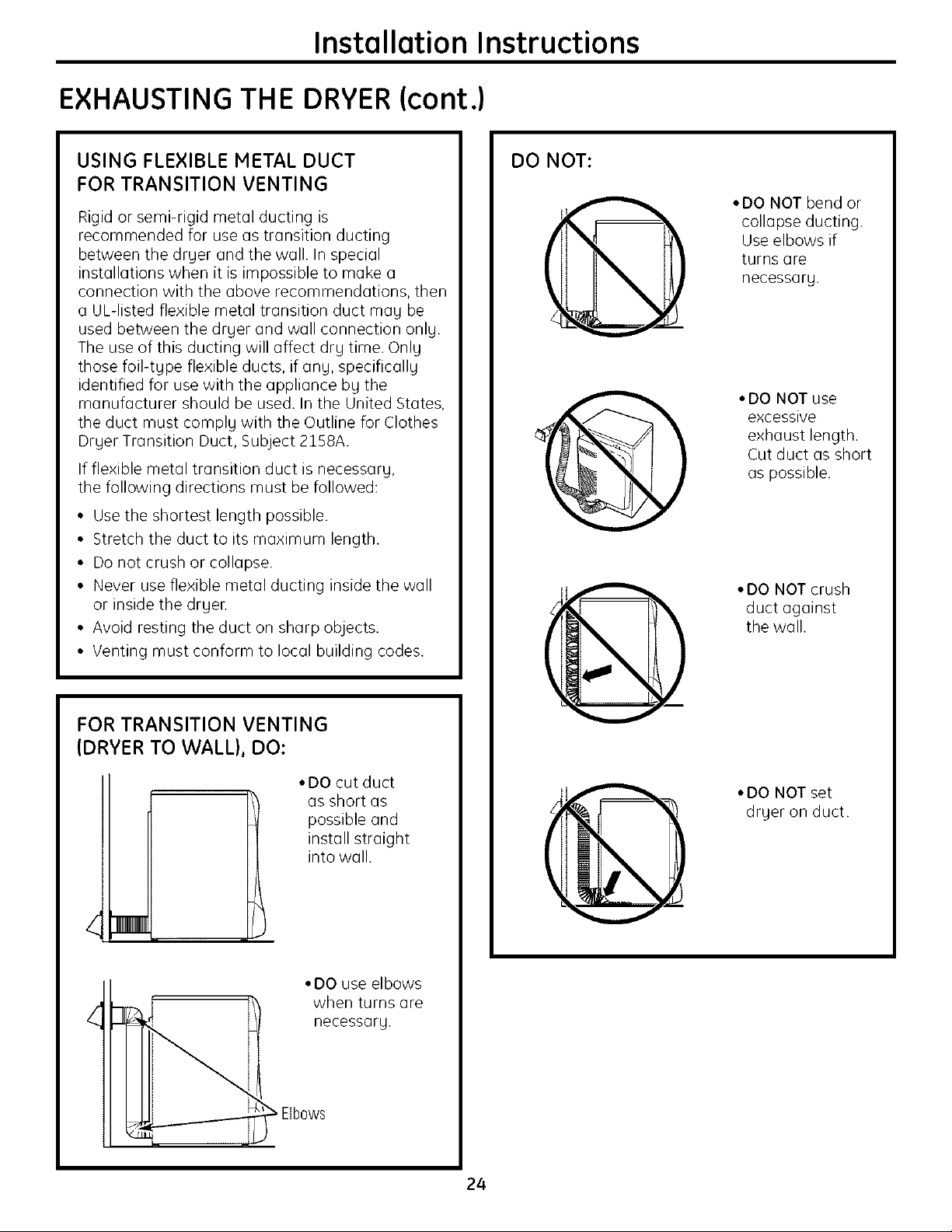
USING FLEXIBLE METAL DUCT
FOR TRANSITION VENTING
Rigid or semi-rigid metal ducting is
recommended for use as transition ducting
between the drger and the wall. In special
installations when it is impossible to make a
connection with the above recommendations, then
a UL-listed flexible metal transition duct mag be
used between the drger and wall connection onlg.
The use of this ducting will affect drg time. Onlg
those foil-tgpe flexible ducts, if ang, specificallg
identified for use with the appliance bg the
manufacturer should be used. In the United States,
the duct must complg with the Outline for Clothes
Drger Transition Duct, Subject 2158A.
If flexible metal transition duct is necessarg,
the following directions must be followed:
• Use the shortest length possible.
• Stretch the duct to its maximum length.
• Do not crush or collapse.
• Never use flexible metal ducting inside the wall
or inside the drgen
• Avoid resting the duct on sharp objects.
• Venting must conform to local building codes.
DO NOT:
IR
)
• DO NOT bend or
collapse ducting.
Use elbows if
turns are
necessarg.
• DO NOT use
excessive
exhaust length.
Cut duct as short
as possible.
• DO NOT crush
duet against
the wall.
FOR TRANSITION VENTING
(DRYER TO WALL), DO:
• DO cut duct
Elbows
as short as
possible and
install straight
into wall.
• DO use elbows
when turns are
necessarg.
• DO NOT set
drger on duct.
24
Installation Instructions
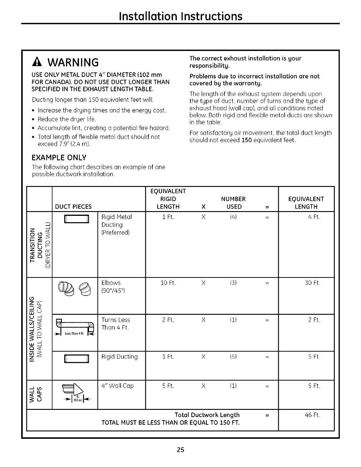
-A WARNING
USE ONLY METAL DUCT 4" DIAMETER (102 mm
FOR CANADA). DO NOT USE DUCT LONGER THAN
SPECIFIED IN THE EXHAUST LENGTH TABLE.
Ducting longer than 150 equivalent feet will:
• Increase the drging times and the energg cost.
• Reduce the drger life.
• Accumulate lint, creating a potential fire hazard.
• Total length of flexible metal duct should not
exceed 7.9' (2.4 m).
EXAMPLE ONLY
The following chart describes an example of one
possible ductwork installation.
EQUIVALENT
RIGID NUMBER EQUIVALENT
DUCT PIECES LENGTH X USED = LENGTH
Rigid Metal
3
Ducting
(Preferred)
The correct exhaust installation is gour
responsibilitg.
Problems due to incorrect installation are not
covered bg the warrantg.
The length of the exhaust sgstem depends upon
the tgpe of duct, number of turns and the tgpe of
exhaust hood (wall cap), and all conditions noted
below. Both rigid and flexible metal ducts are shown
in the table.
For satisfactorg air movement, the total duct length
should not exceed 150 equivalent feet.
1 Ft. X (4) = /4 Ft.
Elbows
10 Ft. X (3)
(90°/45°)
o
z_
u
Turns Less
.-.1
a<
•-J _.
_m_ tessThan4 R
_ _ 4" Wall Cap 5 Ft. X (1) = 5 Ft.
Than 4 Ft.
Rigid Ducting 1 Ft. X (5) = 5 Ft.
TOTAL MUST BE LESS THAN OR EQUAL TO 150 FT.
2 Ft. X (1)
Total Ductwork Length = 46 Ft.
25
30 Ft.
2 Ft.
Installation Instructions
EXHAUSTING THE DRYER(cont.)
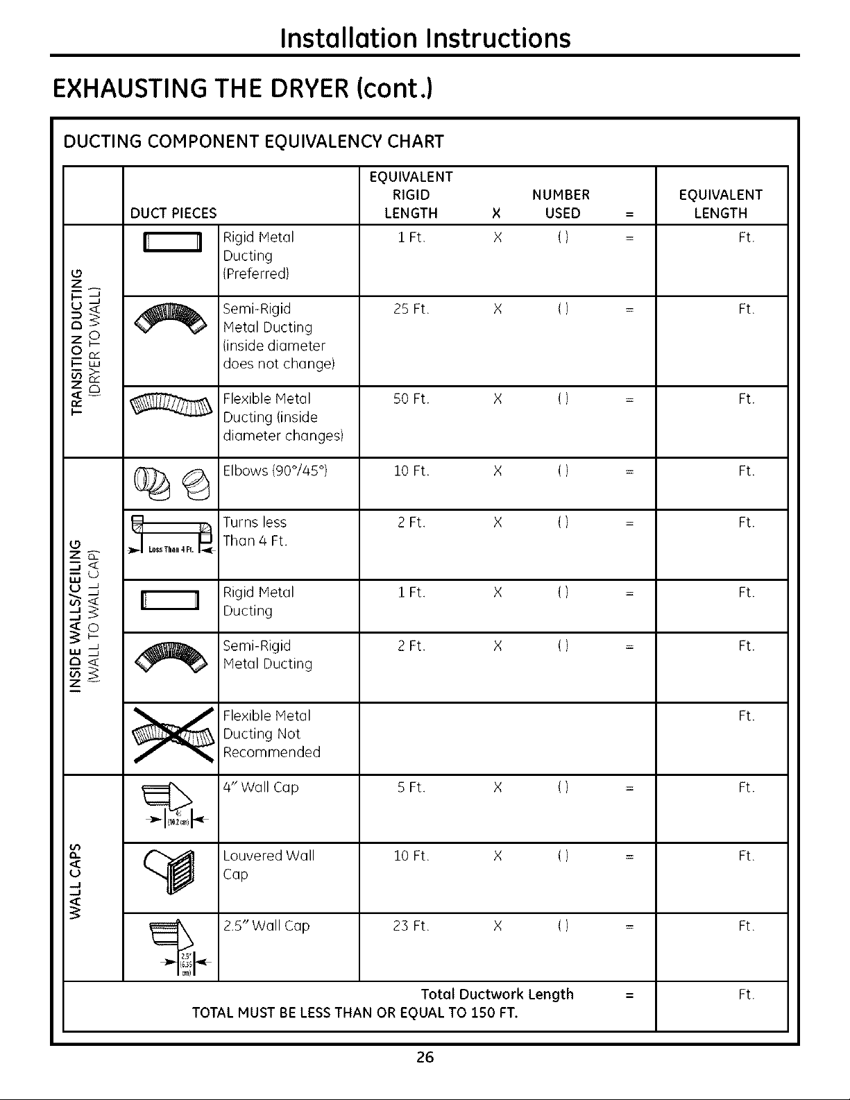
DUCTING COMPONENT EQUIVALENCY CHART
EQUIVALENT
RIGID NUMBER EQUIVALENT
DUCT PIECES LENGTH × USED = LENGTH
Rigid Metal 1 Ft. X () = Ft.
Ducting
Z
BJ
_ 25 Ft. X () = Ft.
_2
I-- LU
_3
< -- Flexible Metal 50 Ft. X () Ft.
(Preferred)
Semi-Rigid
Metal Ducting
(inside diameter
does not change)
Ducting (inside
diameter changes)
_ Elbows{90°/45 °) 10 Ft. X () = Ft.
_ Turns less 2 Ft. X () = Ft.
z_
u
_' _ Ducting
Than 4 Ft.
Rigid Metal 1 Ft. X () = Ft.
S°p-
o < Metal Ducting
u<°- (_ capL°UveredWall 10 Ft. X ( ) = Ft.
-.I
_ Semi-Rigid 2 Ft. X () = Ft.
Flexible Metal Ft.
Ducting Not
Recommended
4" Wall Cap 5 Ft. X ( ) = Ft.
_ 2.5" Wall Cap 23Ft. X () = Ft.
{_35
25"p
Cm)
Total Ductwork Length -- Ft.
TOTAL MUST BE LESS THAN OR EQUAL TO 150 FT.
26
Installation Instructions
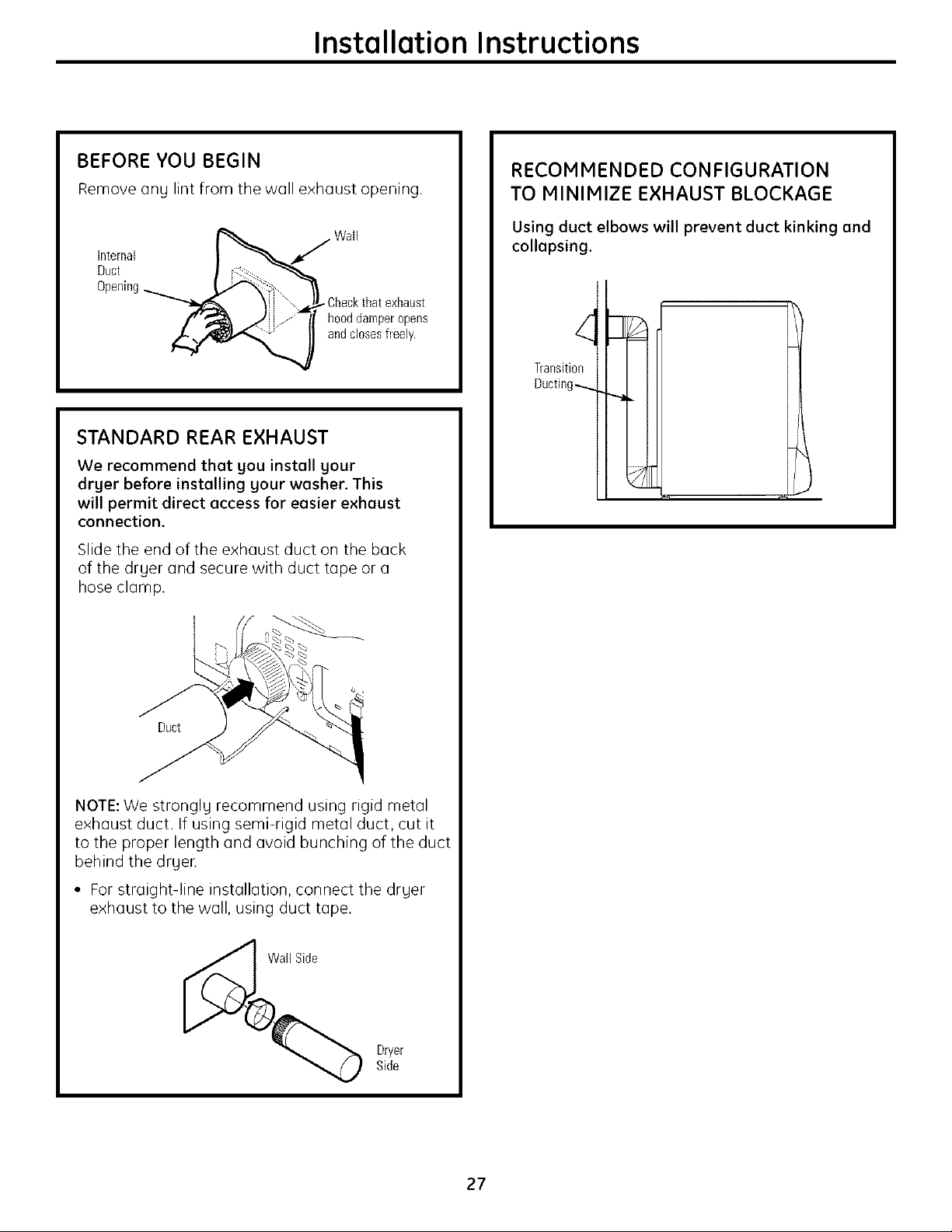
BEFORE YOU BEGIN
Remove ang lint from the wall exhaust opening.
Ductlnternal _ Wall
Opening
\ _ _Checkthat exhaust
J _ _/ hoeddamperopens
and closes freely.
STANDARD REAR EXHAUST
We recommend that gou install gour
drger before installing gour washer. This
will permit direct access for easier exhaust
connection.
Slide the end of the exhaust duct on the back
of the dryer and secure with duct tape or a
hose clamp.
RECOMMENDED CONFIGURATION
TO MINIMIZE EXHAUST BLOCKAGE
Using duct elbows will prevent duct kinking and
collapsing.
Transiti0e
Ducting......
1
Duct
NOTE: We stronglg recommend using rigid metal
exhaust duct. If using semi-rigid metal duct, cut it
to the proper length and avoid bunching of the duct
behind the dryer.
• For straight-line installation, connect the drger
exhaust to the wall, using duct tape.
Dryer
Side
27
Installation Instructions
EXHAUSTING THE DRYER(cont.)
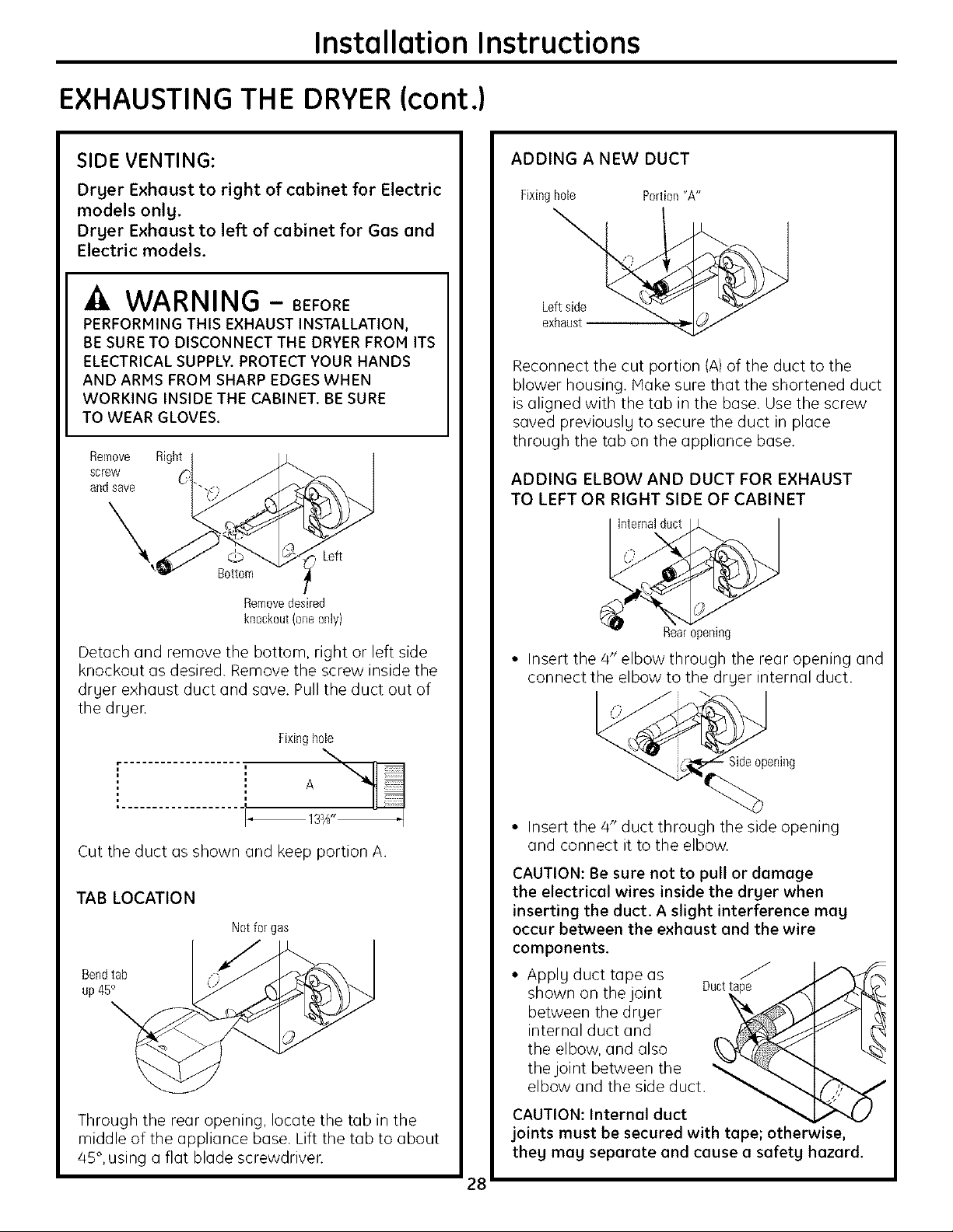
SIDE VENTING:
Drger Exhaust to right of cabinet for Electric
models onlg.
Drger Exhaust to left of cabinet for Gas and
Electric models.
WARNING - BEFORE
PERFORMING THIS EXHAUST INSTALLATION,
BE SURE TO DISCONNECT THE DRYER FROM ITS
ELECTRICAL SUPPLY. PROTECT YOUR HANDS
AND ARMS FROM SHARP EDGES WHEN
WORKING INSIDE THE CABINET. BE SURE
TO WEAR GLOVES.
Remove Right
screw
andsave
Left
Bottom
Removedesired
knockout(oneonly)
Detach and remove the bottom, right or left side
knockout as desired. Remove the screw inside the
drger exhaust duct and save. Pull the duct out of
the drger.
ADDING A NEW DUCT
Fixinghole Portion"A"
Leftside
exhaust
Reconnect the cut portion (A)of the duct to the
blower housing. Make sure that the shortened duct
is aligned with the tab in the base. Use the screw
saved previouslg to secure the duct in place
through the tab on the appliance base.
ADDING ELBOW AND DUCT FOR EXHAUST
TO LEFT OR RIGHT SIDE OF CABINET
Internalduct
Rearopening
• Insert the 4" elbow through the rear opening and
connect the elbow to the drger internal duct.
Fixinghole
A
i ....................
_133/¢"
Cut the duct as shown and keep portion A.
TAB LOCATION
Notfor gas
Bendtab
up 45°
Through the rear opening, locate the tab in the
middle of the appliance base. Lift the tab to about
/45°, using a flat blade screwdriver.
Sideopening
• Insert the/4" duct through the side opening
and connect it to the elbow.
CAUTION: Be sure not to pull or damage
the electrical wires inside the drger when
inserting the duct. A slight interference mag
occur between the exhaust and the wire
components.
• Applg duct tape as
shown on the joint
between the drger
internal duct and
the elbow, and also
the joint between the
elbow and the side duct.
CAUTION: Internal duct
joints must be secured with tape; otherwise,
theg mag separate and cause a safetg hazard.
28
Installation Instructions
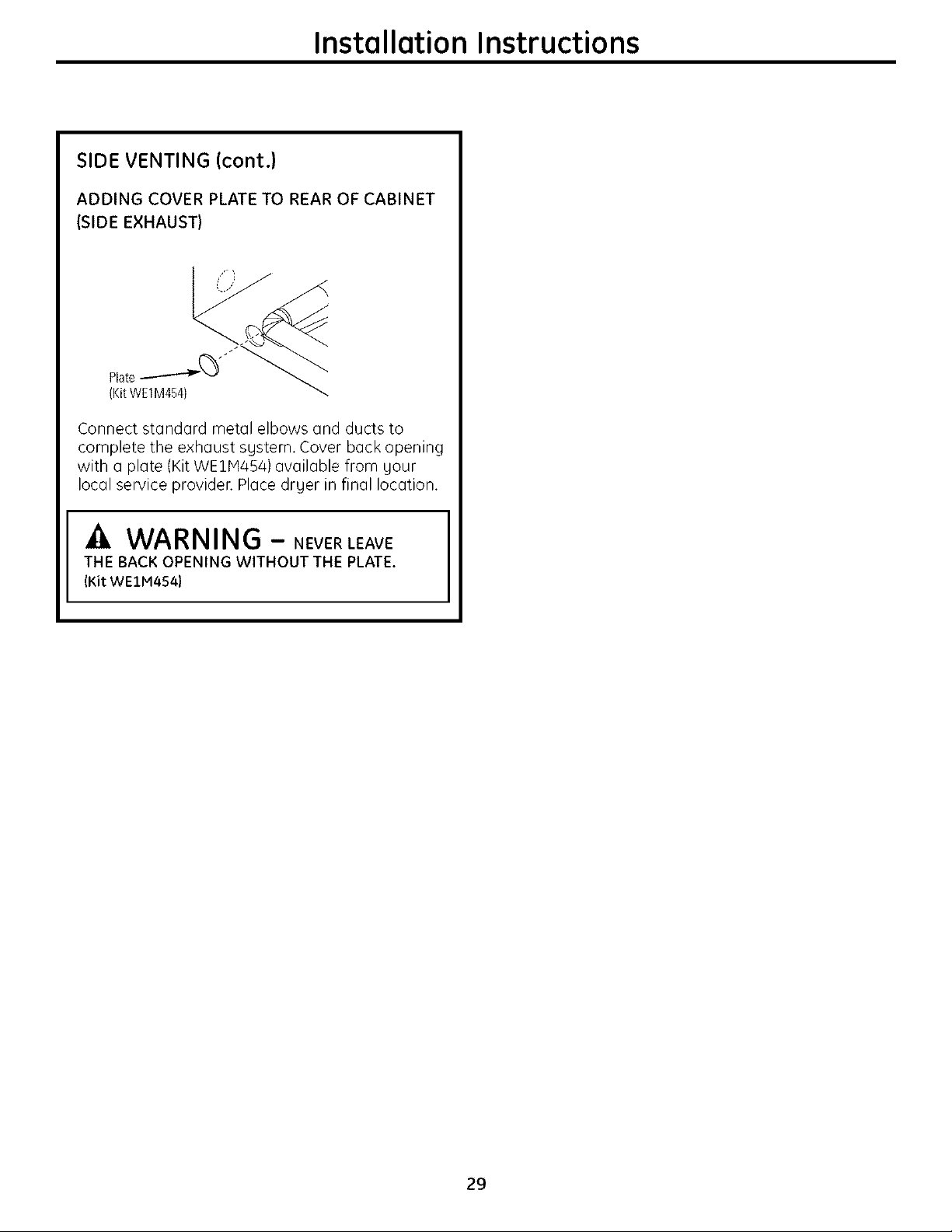
SIDE VENTING (cont.)
ADDING COVER PLATE TO REAR OF CABINET
(SIDE EXHAUST)
Connect standard metal elbows and ducts to
complete the exhaust sgstem. Cover back opening
with a plate (KitWE1H454) available from gour
local service provider. Place drger in final location.
THE BACK OPENING WITHOUT THE PLATE.
_ WARNING- NEVERLEAVE
(Kit WEIM454)
29
Installation Instructions
EXHAUSTING THE DRYER(cont.)
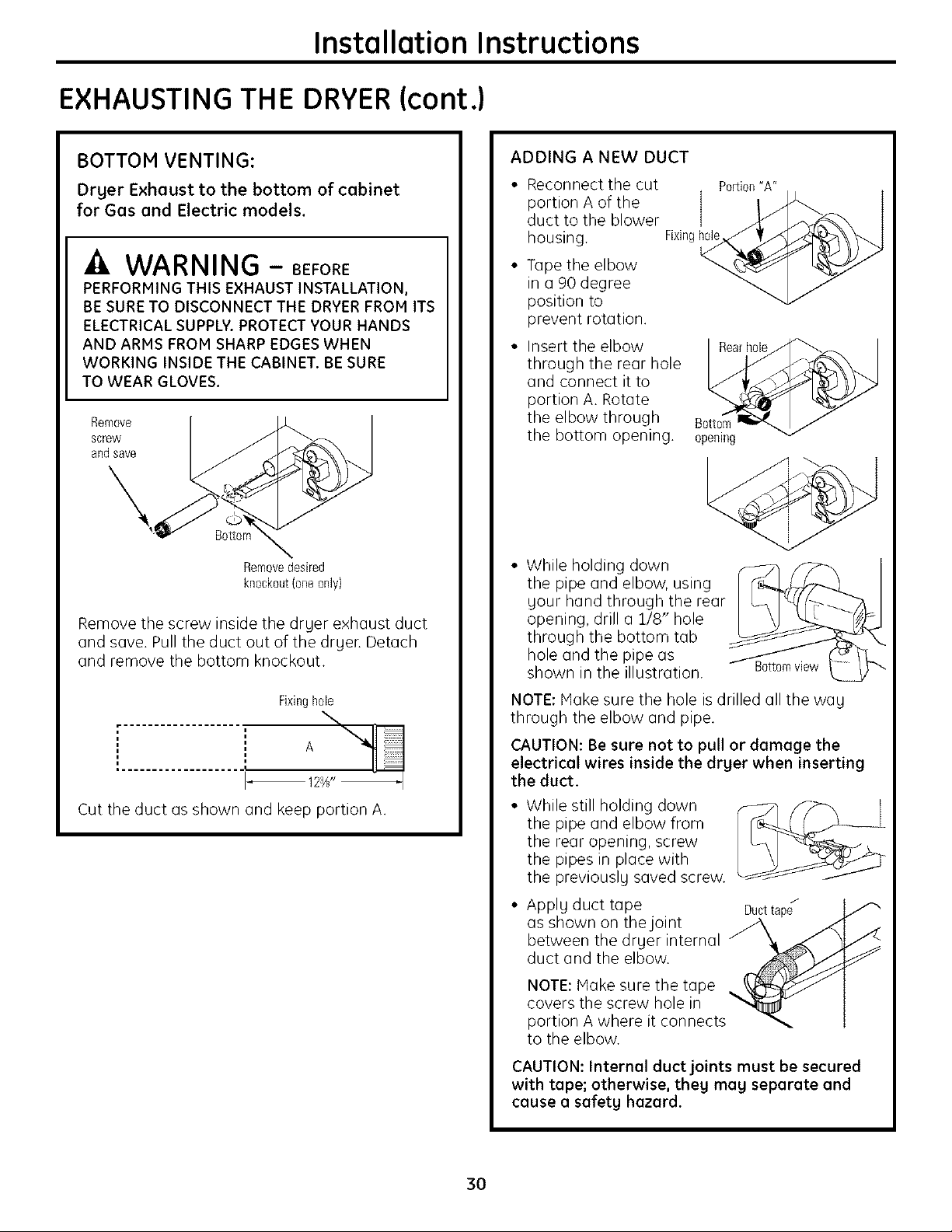
BOTTOM VENTING:
Dryer Exhaust to the bottom of cabinet
for Gas and Electric models.
Ik WARNING - BEFORE
PERFORMING THIS EXHAUST INSTALLATION,
BE SURE TO DISCONNECT THE DRYER FROH ITS
ELECTRICAL SUPPLY. PROTECT YOUR HANDS
AND ARMS FROM SHARP EDGES WHEN
WORKING INSIDE THE CABINET. BE SURE
TO WEAR GLOVES.
Remove
screw
aRdsave
B0ttor
Removedesired
kn0ckeut(0oeonly)
Remove the screw inside the druer exhaust duct
and save. Pull the duct out of the druer. Detach
and remove the bottom knockout.
ADDING A NEW DUCT
• Reconnect the cut
portion A of the
duct to the blower
housing.
• Tape the elbow
in a 90 degree
position to
prevent rotation.
• Insert the elbow
through the rear hole
and connect it to
portion A. Rotate
the elbow through
the bottom opening.
• While holding down _ f_-_
the pipe and elbow, using
uour hand through the rear
opening, drill a 1/8" hole
through the bottom tab
hole and the pipe as
shown in the illustration.
Fixiog[_
Porfioo"A"
opeoing
Fixinghole
A
Cut the duct as shown and keep portion A.
NOTE: Hake sure the hole is drilled all the wag
through the elbow and pipe.
CAUTION: Be sure not to pull or damage the
electrical wires inside the drger when inserting
the duct.
• While still holding down
the pipe and elbow from
the rear opening, screw
the pipes in place with
the previously saved screw.
• Applg duct tape
as shown on thejoint
between the drger internal
duct and the elbow.
NOTE: Hake sure the tape
covers the screw hole in
portion A where it connects
to the elbow.
CAUTION: Internal duct joints must be secured
with tape; otherwise, theg mag separate and
cause a safetg hazard.
Ducttape_
3O
 Loading...