

GE DPVH880EJWW, DPVH880EJ, DPVH880GJMG, DPVH880GJMV, DPVH880GJWW Owner's Manual & Installation Instructions
...Page 1

GEAppliances.com
Profile
Safety Instructions . . .. . . . . . . . 2–4
Operating Instructions
Controls . . . . . . . . . . . . . . . . . . . . . . . . . . .5–8
Cycle Options .. . . . . . . . . . . . . . . . . . .9, 10
Dryer Features . . . . . . . . . . . . . . . . . .10, 11
Quick Start Guide .. . . . . . . . . . . . . . . . . . .5
Settings Option . . . . . . . . . . . . . . . . . . . . .10
Using the Dryer . . . . . . . . . . . . . . . . . . . . .12
Installation Instructions
Before You Begin . . . . . . . . . . . . . . .13–14
Connecting a Gas Dryer . . . . . . . .16–19
Connecting an
Electric Dryer . . . . . . . . . . . . . . . . . . .20–22
Exhausting the Dryer . . . . . . . . . . .23–31
Final Setup . . . . . . . . . . . . . . . . . . . . . .32, 33
Installing the Pedestal . . . . . . . . . .43–45
Location of your Dryer . . . . . . . . . .14–15
Reversing the Door Swing . . . . . .34–39
Stacking the Washer
and Dryer . . . . . . . . . . . . . . . . . . . . . . .40–42
Troubleshooting Tips . . . . . .46–48
Owner’s Manual &
Installation Instructions
DPVH880
UPVH880
Sécheuses
Profile
Manuel d’utilisation
et d’installation
La section française commence à la page 51
Secadoras
Profile
Manual del propietario
e instalación
La sección en español empieza en la página 101
Consumer Support
Consumer Support . . . . . . . Back Cover
Warranty (Canada) . . . . . . . . . . . . . . . . . 50
Warranty (U.S.) . . . . . . . . . . . . . . . . . . . . . 49
Dryers
SAVE THESE INSTRUCTIONS
Write the model and serial
numbers here:
Model # ______________
Serial # ________________
They are on the label on the front
of the dryer behind the door.
175D1807P638 49-90376 05-09 JR
Page 2
IMPORTANT SAFETY INFORMATION.
READ ALL INSTRUCTIONS BEFORE USING.
WARNING!
For your safety, the information in this manual must be followed to minimize the risk
of fire or explosion, electric shock, or to prevent property damage, personal injury,
or death.
■ Do not store or use gasoline or other
flammable vapors and liquids in the
vicinity of this or any other appliance.
■ Installation and service must be
performed by a qualified installer,
service agency or the gas supplier.
WHAT TO DO IF YOU SMELL GAS:
Do not try to light a match, or
1
cigarette, or turn on any gas or
electrical appliance.
Do not touch any electrical switch;
2
do not use any phone in your building.
Clear the room, building or area
3
of all occupants.
Operating Instructions Safety InstructionsConsumer Support Troubleshooting Tips
California Safe Drinking Water and Toxic Enforcement Act
This act requires the governor of California to publish a list of substances known to the state to cause cancer,
birth defects or other reproductive harm and requires businesses to warn customers of potential exposure to
such substances.
Gas appliances can cause minor exposure to four of these substances, namely benzene, carbon monoxide,
formaldehyde and soot, caused primarily by the incomplete combustion of naturalgas or LP fuels.
Properly adjusted dryers will minimize incomplete combustion. Exposure to these substances can be
minimized further by properly venting the dryer to the outdoors.
Immediately call your gas supplier
4
from a neighbor’s phone. Follow the
gas supplier’s instructions carefully.
If you cannot reach your gas supplier,
5
call the fire department.
PROPER INSTALLATION
This dryer must be properly installed and located in accordance with the Installation Instructions
before it is used. Installation Instructions are included in the back of this manual.
■ Properly ground dryer to conform with all
governing codes and ordinances. Follow details
in Installation Instructions.
■ Install or store where it will not be exposed to
temperatures below freezing or exposed to water
or weather.
■ Connect to a properly rated, protected and sized
power supply circuit to avoid electrical overload.
■ Remove all sharp packing items and dispose of
all shipping materials properly.
2
Exhaust/Ducting
Dryers MUST be exhausted to the outside to
1
prevent large amounts of moisture and lint from
being blown into the room.
Use only rigid metal 4″ diameter ductwork inside
2
the dryer cabinet. Use only rigid metal or flexible
metal 4-in diameter ductwork for exhausting to
the outdoors. Never use plastic or other
combustible, easy-to-puncture ductwork.
For complete details, follow the Installation
Instructions.
Page 3
WARNING!
YOUR LAUNDRY AREA
■ Keep the area underneath and around your
appliances free of combustible materials,
(lint, paper, rags, etc.), gasoline, chemicals
and other flammable vapors and liquids.
■ Keep the floor around your appliances clean
and dry to reduce the possibility of slipping.
■ Close supervision is necessary if this appliance is
used by or near children. Do not allow children to
play on, with or inside this or any other appliance.
WHEN USING YOUR DRYER
■ Never reach into the dryer while the drum is
moving. Before loading, unloading or adding
clothes, wait until the drum has completely
stopped.
GEAppliances.com
■ Keep the area around the exhaust opening
and adjacent surrounding areas free from the
accumulation of lint, dust and dirt.
■ Keep all laundry aids (such as detergents,
bleaches, etc.) out of the reach of children,
preferably in a locked cabinet. Observe all
warnings on container labels to avoid injury.
■ Never climb on or stand on the dryer top.
■ The laundry process can reduce the flame
retardancy of fabrics. To avoid such a result,
carefully follow the garment manufacturer’s
care instructions.
■ Clean the lint filter before each load to prevent lint
accumulation inside the dryer or in the room. DO
NOT OPERATE THE DRYER WITHOUT THE LINT
FILTER IN PLACE.
■ Do not wash or dry articles that have been
cleaned in, washed in, soaked in or spotted
with combustible or explosive substances (such as
wax, oil, paint, gasoline, degreasers, dry-cleaning
solvents, kerosene, etc.). These substances give
off vapors that may ignite or explode. Do not add
these substances to the wash water. Do not use
or place these substances around your washer
or dryer during operation.
■ Do not place items exposed to cooking oils in
your dryer. Items contaminated with cooking oils
may contribute to a chemical reaction that could
cause a clothes load to catch fire.
■ Any article on which you have used a cleaning
solvent or that contains flammable materials
(such as cleaning cloths, mops, towels used in
beauty salons, restaurants or barber shops, etc.)
must not be placed in or near the dryer until
solvents or flammable materials have been
removed. There are many highly flammable items
used in homes such as acetone, denatured alcohol,
gasoline, kerosene, some household cleaners, some
spot removers, turpentines, waxes, wax removers
and products containing petroleum distillates.
■ Do not dry articles containing rubber, plastic
or similar materials such as padded bras, tennis
shoes, galoshes, bath mats, rugs, bibs, baby pants,
plastic bags, pillows, etc. that may melt or burn.
Some rubber materials, when heated, can under
certain circumstances produce fire by spontaneous
combustion.
■ Do not store plastic, paper or clothing that may
burn or melt on top of the dryer during operation.
■ Garments labeled Dry Away from Heat or Do Not
Tumble Dry (such as life jackets containing Kapok)
must not be put in your dryer.
■ Do not dry fiberglass articles in your dryer.
Skin irritation could result from the remaining
particles that may be picked up by clothing
during subsequent dryer uses.
■ To minimize the possibility of electric shock, unplug
this appliance from the power supply or disconnect
the dryer at the household distribution panel by
removing the fuse or switching off the circuit
breaker before attempting any maintenance or
cleaning (except the removal and cleaning of the
lint filter). NOTE: Pressing START/PAUSE or POWER
does NOT disconnect the appliance from the power
supply.
Consumer SupportTroubleshooting TipsOperating InstructionsSafety Instructions
3
Page 4
IMPORTANT SAFETY INFORMATION.
READ ALL INSTRUCTIONS BEFORE USING.
WARNING!
WHEN USING YOUR DRYER (cont.)
■ Never attempt to operate this appliance if it is
damaged, malfunctioning, partially disassembled,
or has missing or broken parts, including a
damaged cord or plug.
■ The interior of the machine and the exhaust duct
connection inside the dryer should be cleaned at
least once a year by a qualified technician. See
the Sorting and Loading Hints section on page 12.
■ If yours is a gas dryer, it is equipped with an
automatic electric ignition and does not have
a pilot light. DO NOT ATTEMPT TO LIGHT WITH
A MATCH. Burns may result from having your hand
in the vicinity of the burner when the automatic
ignition turns on.
■ You may wish to soften your laundered fabrics
or reduce the static electricity in them by using
a dryer-applied fabric softener or an anti-static
conditioner. We recommend you use either a
fabric softener in the wash cycle, according to
the manufacturer’s instructions for those products,
or try a dryer-added product for which the
manufacturer gives written assurance on the
package that their product can be safely used
in your dryer. Service or performance problems
caused by use of these products are the
responsibility of the manufacturers of those
products and are not covered under the
warranty of this appliance.
WHEN NOT USING YOUR DRYER
Operating Instructions Safety InstructionsConsumer Support Troubleshooting Tips
■ Grasp the plug firmly when disconnecting this
appliance to avoid damage to the cord while
pulling. Place the cord away from traffic areas
so it will not be stepped on, tripped over or
subjected to damage.
■ Do not attempt to repair or replace any part of
this appliance or attempt any servicing unless
specifically recommended in this Owner’s Manual
or in published user-repair instructions that you
understand and have the skills to carry out.
■ Before discarding a dryer, or removing it from
service, remove the dryer door to prevent children
from hiding inside.
■ Do not tamper with controls.
READ AND FOLLOW THIS SAFETY INFORMATION CAREFULLY.
SAVE THESE INSTRUCTIONS
4
Page 5
About the dryer control panel.
GEAppliances.com
WARNING! To reduce the risk of fire, electric shock, or injury to persons, read the IMPORTANT
SAFETY INSTRUCTIONS before operating this appliance.
Throughout this manual, features and appearance may vary from your model.
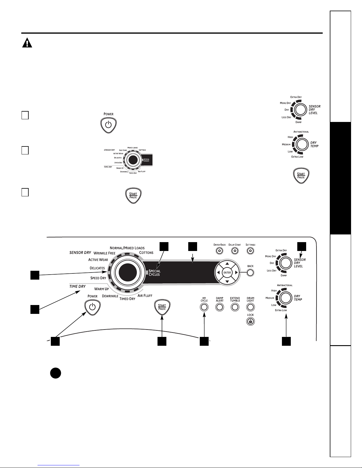
Quick Start
If the screen is dark, press the POWER button to “wake up”
the display.
Press the
1
Select a cycle by turning the
2
Cycle Knob.
If you selected a SENSOR CYCLE – just
3
press the START/PAUSE button.
POWER
button.
If you selected a TIMED DRY CYCLE –
select your heat setting and the
amount of time you want your items
to dry by using the cursor buttons.
Then press the START/PAUSE button.
49 8
2
3
1
76
5
Consumer SupportTroubleshooting TipsOperating InstructionsSafety Instructions
Power
1
Press to “wake up” the display. If the display is active, press to turn the dryer off.
NOTE: Pressing POWER does not disconnect the appliance from the power supply.
5
Page 6
About the dryer control panel.
Dry Cycles
2
The dry cycle controls the cycle time for the drying process. The chart below will help you match
the dry setting with the loads.
Sensor Cycles
COTTONS For cottons and most linens.
NORMAL/ For loads consisting of cottons and poly-blends.
MIXED LOAD
WRINKLE FREE For wrinkle-free/easy care and permanent press items.
ACTIVE WEAR Clothing worn for active sports exercise and some casual wear. Fabrics include new
DELICATES For lingerie and special-care fabrics.
SPEED DRY For small loads that are needed in a hurry, such as sports or school uniforms. Can also be
Timed Dry Cycles
DEWRINKLE For removing wrinkles from items that are dry or slightly damp. This cycle is not
WARM UP Provides 10 minutes of warming time to warm up clothes.
AIR FLUFF Use this feature to tumble items without heat.
My Cycle (on some models)
Operating Instructions Safety InstructionsConsumer Support Troubleshooting Tips
Timed Dry
3
Use to set your own dry time. TIMED DRY is also recommended for small loads.
To use TIMED DRY:
1. Turn dry cycle dial to TIMED DRY.
2. Select the drying time by pressing the ▲ and ▼ buttons. You can increase the time in 10-minute
3. Select the DRY TEMP.
4. Close the door.
5. Press START/PAUSE.
MY CYCLE Press to use, create or modify custom dry cycles.
increments up to 21⁄2 hours.
technology finishes and stretch fibers such as Spandex.
used if the previous cycle left some items damp, such as collars or waistbands.
recommended for delicate fabrics.
Sensor Dry Level
4
The sensor continuously monitors the amount of moisture in the load. When the moisture in your
clothes reaches your selected dry level, the dryer will stop.
EXTRA DRY Use for heavy-duty fabrics or items that should be very dry, such as towels.
MORE DRY Use for heavy or mixed type of fabrics.
DRY Use for normal dryness level suitable for most loads. This is the preferred cycle
LESS DRY Use for lighter fabric (ideal for ironing).
DAMP For leaving items partially damp.
6
for energy saving.
Page 7
Dry Temp
5
You can change the temperature of your dry cycle.
GEAppliances.com
ANTI-BACTERIAL This option may only be used with COTTONS or MIXED LOAD cycles. This option reduces
HIGH For regular to heavy cottons.
MEDIUM For synthetics, blends and items labeled permanent press.
LOW For delicates, synthetics and items labeled Tumble Dry Low.
EXTRA LOW For lingerie and special-care fabrics.
START/PAUSE
6
Press to start a dry cycle. If the dryer is running, press it once and it will pause the dryer.
Press it again to restart the dry cycle.
7
My Cycle (on some models)
Set up your favorite combination of settings and save them here for one touch recall.
These custom settings can be set while a cycle is in progress.
certain types of bacteria by 99.9%, including: Staphylococcus aureus, Pseudomonas
aeruginosa and Klebsiella pneumoniae*. The anti-bacterial process occurs when high
heat is used during a portion of this drying cycle.
NOTE: Do not use this cycle on delicate fabrics.
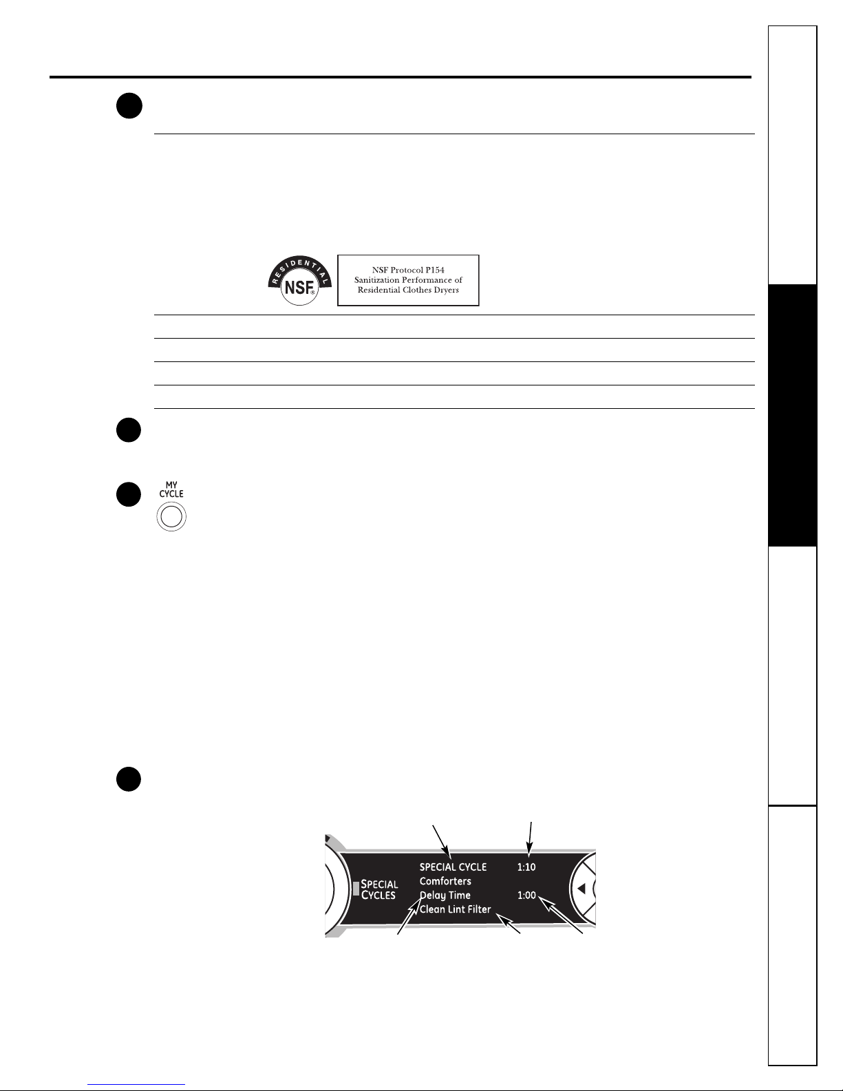
* The Anti-Bacterial Cycle is Certified by NSF International (formerly National Sanitation
Foundation) to NSF Protocol P154 Sanitization Performance of Residential Clothes Dryers.
To store a MY CYCLE combination of settings:
1. Select your drying cycle.
2. Change DRY TEMP and SENSOR DRY LEVEL settings to fit your needs.
3. Select any drying OPTIONS you want.
4. Press and hold the MY CYCLE button for three seconds to store your selection. A beep will sound
and the button will light up.
To recall your stored MY CYCLE combination:
Press the MY CYCLE button before drying a load. The light around the button will light up when
MY CYCLE is selected.
To change your stored MY CYCLE combination:
Follow steps 1–4 in “To store a MY CYCLE combination of settings”.
Display
8
Special Cycle Status OR
Dryer Rack OR Timed Dry
Delay Time
Status
Est. Cycle Time
OR Time to Dry
Lint Filter Status
Screen
DELAY TIME
Consumer SupportTroubleshooting TipsOperating InstructionsSafety Instructions
“CLEAN LINT FILTER” (message)
This message stays on for 15 minutes after the cycle finishes. This message is only a reminder.
7
Page 8
About the dryer control panel.
Specialty Cycles
9
1. Turn the CYCLE knob to SPECIAL CYCLES. A list of cycle options will appear in the display.
2. Using the cursor buttons, select a CATEGORY.
3. Using the cursor buttons, select a CYCLE.
Press the BACK button to take you back to the CATEGORIES.
4. Press ENTER to select.
5. Press the START/PAUSE button.
SPECIALTY CYCLES include:
Garments
■ Jeans
■ Khakis
■ Coats
■ Hosiery/Bras (use mesh bag)
Bed and Bath
■ Towels
■ Sheets
■ Blankets (Cotton)
■ Down Pillows/Comforters
Other Specialty
■ Throw Rugs
■ Pet Bedding
Operating Instructions Safety InstructionsConsumer Support Troubleshooting Tips
■ Performance Garments
■ Fleece
■ Dryel
■ Fragile Cotton
■ Dryer Rack
Washer Communicated Cycles
To turn on communication, press the
SETTINGS button on the washer control
panel. When “DRYER LINK” appears in the
display, press ENTER. Using the arrow keys,
select ON; then press ENTER.
When the washer cycle is completed, the
washer will communicate with the dryer
when any button on the control panel is
touched or the door is opened.
The washer will display, “TRANSFERRING
CYCLE INFORMATION TO THE DRYER” and
the dryer will display, “RECEIVING CYCLE
INFORMATION TO THE DRYER”.
The dryer will only communicate with the
washer if the dryer is not running a cycle.
If the washer starts a new cycle before the
dryer has a chance to communicate with
it, the information will be lost.
8
Page 9
About cycle options.
NOTE: Not all features are available on all dryer models. GEAppliances.com
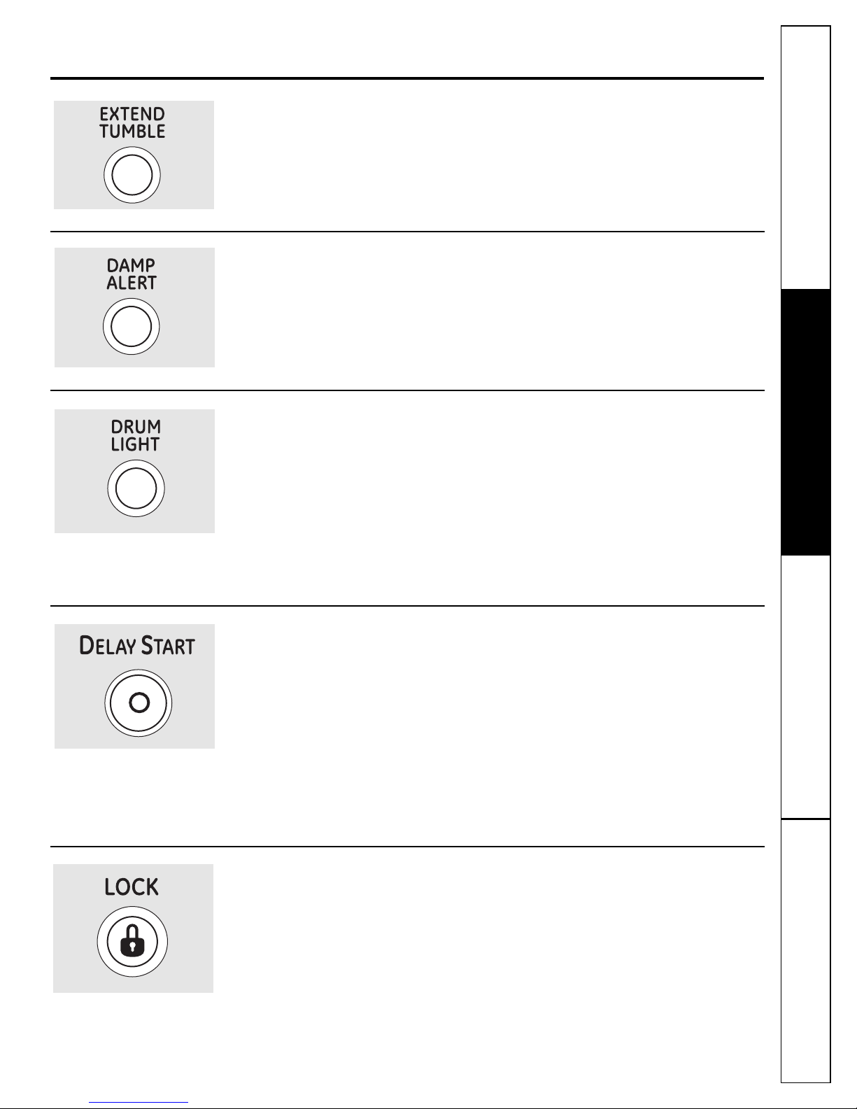
Extend Tumble
Minimizes wrinkles by adding approximately
60 minutes of no-heat tumbling after clothes
are dry.
Damp Alert
This option causes the dryer to beep when
clothes have dried to a damp level. Remove
items that you wish to hang dry. The DAMP
ALERT will only beep when this option is
selected.
Drum Light
Press this button to turn on the light in the
dryer.
Press the button again to turn the light off.
This only controls the light when the door
is shut. NOTE: The light will turn off by itself
after one minute when the door is shut.
The light around the button will light up when
EXTEND TUMBLE is on.
Removing clothes and hanging them when
they are damp can reduce the need to iron
some items.
The light around the button will light up when
DAMP ALERT is on.
The light around the button will light up when
DRUM LIGHT is on.
When the door is opened, the light comes
on automatically.
Delay Start
Use to delay the start of your dryer.
1. Choose your dry cycle and any options.
2. Press DELAY START. You can change the
delay time in 1/2 hour increments, using
the ▲ or ▼ arrow pads.
3. Press the START/PAUSE button to start
the countdown.
The countdown time will be shown in the
ESTIMATED TIME REMAININGdisplay.
Lock
You can lock the controls to prevent any
selections from being made. Or you can lock
the controls after you have started a cycle.
Children cannot accidentally start the dryer
by touching pads with this option selected.
NOTES:
■ If the door is opened while the dryer is
in DELAY, the countdown time will not
restart unless the door is closed and
START/PAUSE button has been pressed
again.
■ You can delay the start of a dry cycle up
to 24 hours.
The light around the button will light up when
DELAY START is on.
Consumer SupportTroubleshooting TipsOperating InstructionsSafety Instructions
To lock the dryer, press the LOCK button. To
unlock the dryer, press and hold the LOCK
button for 3 seconds.
The light around the LOCK button will light up
when the controls are locked.
Press to lock control.
Hold 3 seconds to unlock.
Even though the controls are locked, the
POWER button is still active in case you have
to turn the unit off.
9
Page 10

About cycle options.
NOTE: Not all features are available on all dryer models.
Settings
About dryer features.
Operating Instructions Safety InstructionsConsumer Support Troubleshooting Tips
Under the SETTINGS option, you can
adjust the volume or the brightness of
the display.
VOLUME
■ End of Cycle (signal) volume can be set
from HIGH, MED, LOW or OFF.
■ Control Sounds volume can be set from
HIGH, MED, LOW or OFF.
Drum Lamp
Before replacing the light bulb, be sure to unplug the dryer power cord or
disconnect the dryer at the household distribution panel by removing the
fuse or switching off the circuit breaker. Reach above dryer
inside the drum. Remove the
DISPLAY BRIGHTNESS can be set from
HIGH, MED or LOW.
After you have made your selection,
press ENTER.
opening from
bulb and replace with the same size bulb.
Engage the handle posts
Built-in Rack Dry System™with TumbleCare Baffles
A handy drying rack may be used for drying items such as tennis shoes.
Place items flat on the drying rack and block such items as wool sweaters
and delicate fabrics. Dry with low heat.
To install the Built-in Rack Dry System™with TumbleCare Baffles
1. Make sure the drum of the dryer is oriented so the rack drying system is
on the left side of the dryer.
2. Pull the drying rack screen out from the left side and engage the handle
“posts” in the opposite baffle slots.
3. Place the garment on the rack and close the door.
4. Press the DRYING RACK button.
5. Select desired TIME.
6. Press the START/PAUSE button.
NOTE:
■ Do not use this drying rack when there are other clothes in the dryer.
■ Make sure to detach the drying rack at the end of the cycle and fully
retract the screen back into the baffle.
™
™
10
Page 11
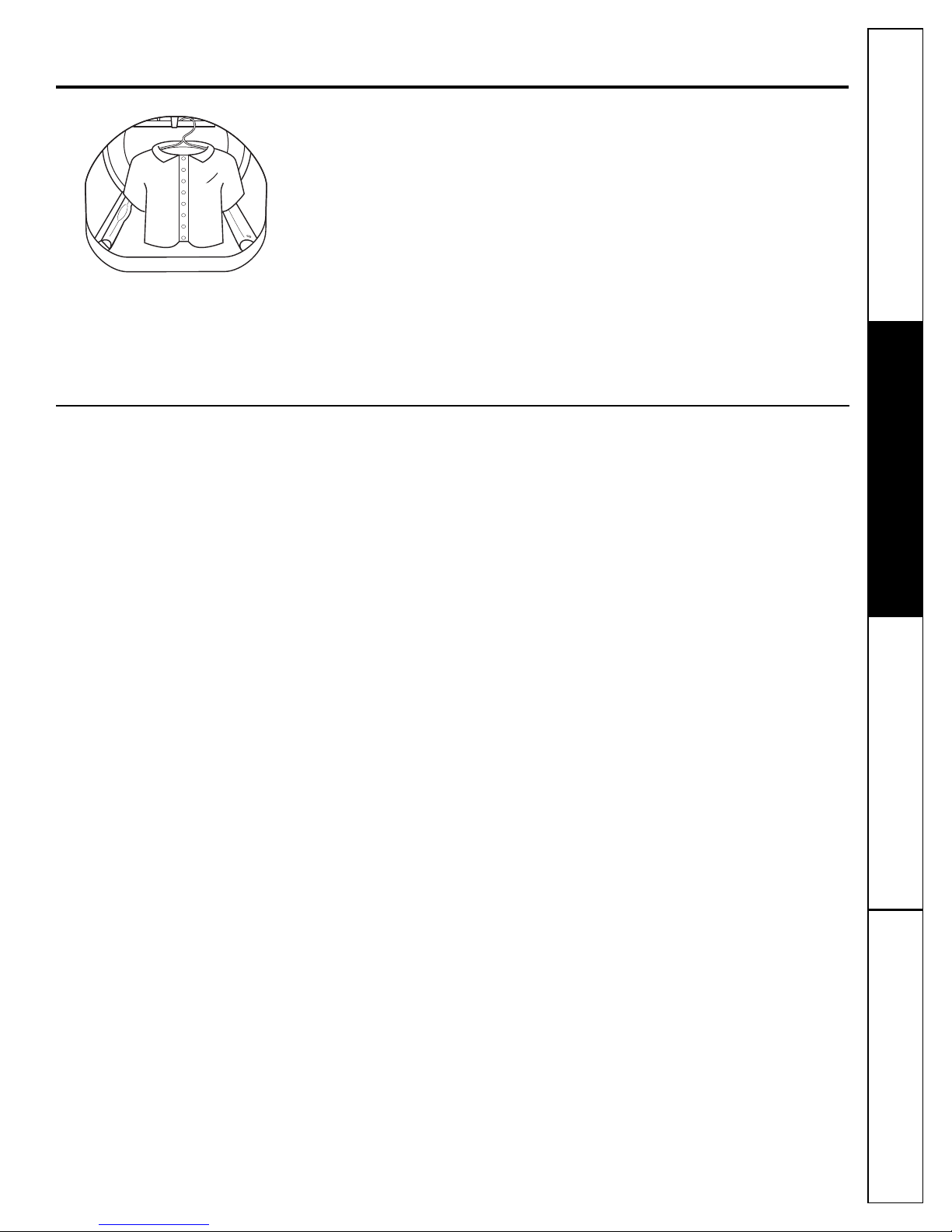
To Use the Built-In Hook
for Hanging Garments
1. Make sure the drum of the dryer is
oriented so the hook is on the top
center of the dryer.
2. Using your finger, pull the hook out
of the baffle.
3. Hang the garment on a hanger,
hang the hanger on the hook and
close the door.
4. Press the DRYING RACK button.
5. Select the desired time.
6. Press the START/PAUSE button.
GEAppliances.com
Reverse Tumble
All Profile front load matching dryers are equipped with the Reverse Tumble
feature, as part of the Duo Dry Plus system™. By reversing the direction
of drum rotation during the drying cycle, your dryer will tangle the clothes
load less, dry more evenly and improve drying times. Typical loads such
as bed and bath mixed loads, where sheets, towels and pillow cases are
laundered together, benefit from this capability. When the dryer reverses
direction, there will be a slight pause and sound change. This is normal.
All dryer cycles utilize this feature, except when the rack dry option is selected,
in which case the drum does not tumble.
™
™
Consumer SupportTroubleshooting TipsOperating InstructionsSafety Instructions
11
Page 12
Using the dryer.
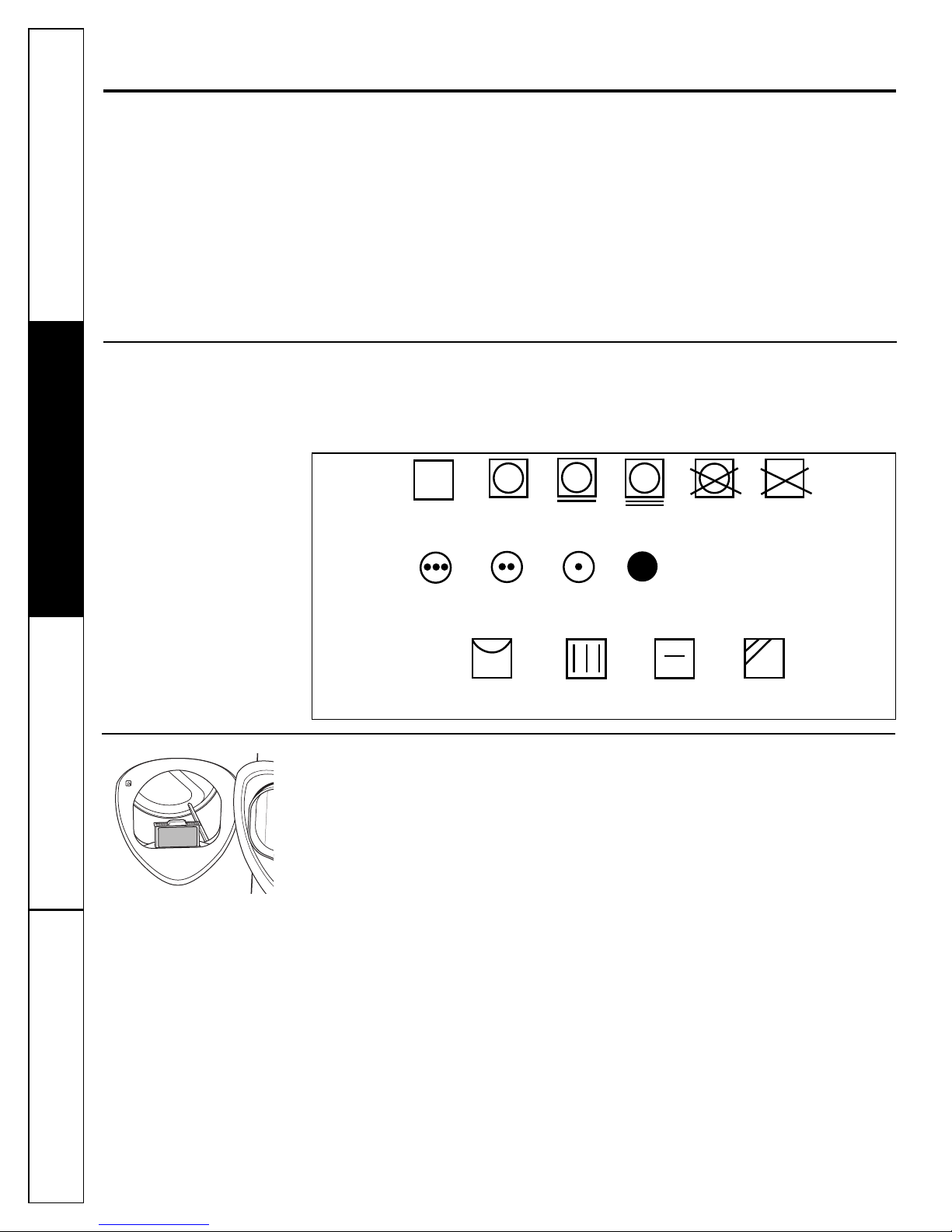
Tumble
dry
Dry
Normal
Permanent Press/
wrinkle resistant
Gentle/
delicate
Do not tumble dry
Do not dry
(used with
do not wash)
Heat
setting
High
Medium
Low
No heat/air
Special
instructions
Line dry/
hang to dry
Drip dry
Dry flat
In the shade
Always follow fabric manufacturer’s care label when laundering.
Sorting and Loading Hints
As a general rule, if clothes are sorted
properly for the washer, they are sorted
properly for the dryer. Try also to sort items
according to size. For example, do not dry
a sheet with socks or other small items.
Do not add fabric softener sheets once
the load has become warm. They may
cause fabric softener stains. Bounce
®
been approved for use in this dryer when
used in accordance with the manufacturer’s
instructions.
See below for lint filter cleaning instructions.
Do not overload. This wastes energy and
causes wrinkling.
Do not dry the following items: fiberglass
items, woolens, rubber-coated items, plastics,
items with plastic trim and foam-filled items.
Fabric Conditioner Dryer Sheets have
Fabric Care Labels
Below are fabric care label “symbols” that
affect the clothing you will be laundering.
Dry Labels
Operating Instructions Safety InstructionsConsumer Support Troubleshooting Tips
Care and Cleaning of the Dryer
Dryer Interior and Duct: The interior of
the appliance and exhaust duct should be
cleaned once a year by qualified service
personnel.
The Exterior: Wipe or dust any spills or
washing compounds with a damp cloth.
Dryer control panel and finishes may be
damaged by some laundry pretreatment
soil and stain remover products. Apply
these products away from the dryer. The
fabric may then be washed and dried
normally. Damage to your dryer caused
by these products is not covered by your
warranty.
Do not touch the surface or the display
with sharp objects.
The Lint Filter: Clean the lint filter before
each use. Remove by pulling straight up.
Run your fingers across the filter. A waxy
buildup may form on the lint filter from
using dryer-added fabric softener sheets.
12
To remove this buildup, wash the lint
screen in warm, soapy water. Dry
thoroughly and replace. Do not operate
the dryer without the lint filter in place.
Vacuum the lint from the dryer lint
filter if you notice a change in dryer
performance.
Stainless Steel: To clean stainless steel
surfaces, use a damp cloth with a mild,
nonabrasive cleaner suitable for stainless
steel surfaces. Remove the cleaner
residue, and then dry with a clean cloth.
The stainless steel used to make
the dryer drum provides the highest
reliability available in a GE dryer. If
the dryer drum should be scratched or
dented during normal use, the drum
will not rust or corrode. These surface
blemishes will not affect the function
or durability of the drum.
The Exhaust Hood: Check with a mirror
that the inside flaps of the hood move
freely when operating. Make sure that
there is no wildlife (birds, insects, etc.)
nesting inside the duct or hood.
Page 13
Installation Dryer
Instructions
Questions? Call 800.GE.CARES (800.432.2737) or visit our Web site at: GEAppliances.com
In Canada, call 1.800.561.3344 or visit www.GEAppliances.ca
BEFORE YOU BEGIN
Read these instructions completely and carefully.
•
IMPORTANT – Save these instructions for local
electrical inspector’s use.
IMPORTANT – Observe all governing codes and
•
ordinances.
• Install the clothes dryer according to the manufacturer’s
instructions and local codes.
• Note to Installer – Be sure to leave these instructions
with the Consumer.
• Note to Consumer – Keep these instructions for future
reference.
• Clothes dryer installation must be performed by a
qualified installer.
• This dryer must be exhausted to the outdoors.
• Before the old dryer is removed from service or
discarded, remove the dryer door.
• Service information and the wiring diagram are located
in the control console.
• Do not allow children on or in the appliance. Close
supervision of children is necessary when the appliance
is used near children.
• Proper installation is the responsibility of the installer.
• Product failure due to improper installation is not
covered under the Warranty
• Install the dryer where the temperature is above 50°F
for satisfactory operation of the dryer control system.
• Remove and discard existing plastic or metal foil duct
and replace with UL-listed duct.
.
FOR YOUR SAFETY:
• To reduce the risk of severe injury or death, follow
• Clothes dryer installation must be performed by a
• Install the clothes dryer according to these
• This dryer must be exhausted to the outdoors.
• Use only 4″ rigid metal ducting for exhausting the
• DO NOT install a clothes dryer with flexible plastic
• Do not install or store this appliance in any location
• The National Fuel Gas Code restricts installations of
• Save these instructions. (Installers: Be sure to leave
DPVH880 and UPVH880
WARNING –
all installation instructions.
qualified installer.
instructions and in accordance with local codes.
clothes dryer to the outdoors.
ducting materials. If flexible metal (semi-rigid or
foil-type) duct is installed, it must be UL-listed and
installed in accordance with the instructions found
in “Connecting the Dryer to House Vent” on page 24
of this manual. Flexible ducting materials are known
to collapse, be easily crushed and trap lint. These
conditions will obstruct dryer airflow and increase
the risk of fire.
where it could be exposed to water and/or weather.
gas appliances in garages. They must be 18 inches
off the ground and protected by a barrier from
vehicles.
these instructions with the customer.)
Risk of Fire
CALIFORNIA SAFE DRINKING WATER AND
TOXIC ENFORCEMENT ACT
This act requires the governor of California to publish a
list of substances known to the state to cause cancer,
birth defects or other reproductive harm and requires
businesses to warn customers of potential exposure to
such substances. Gas appliances can cause minor
exposure to four of these substances, namely benzene,
carbon monoxide, formaldehyde and soot, caused
primarily by the incomplete combustion of natural gas
or LP fuels. Properly adjusted dryers will minimize
incomplete combustion. Exposure to these substances
can be minimized further by properly venting the dryer
to the outdoors.
FOR GAS MODELS ONLY:
NOTE: Installation and service of this dryer must be
performed by a qualified installer, service agency or
the gas supplier.
In the Commonwealth of Massachusetts:
• This product must be installed by a licensed
plumber or gas fitter.
• When using ball-type gas shut-off valves, they
shall be T-handle-type.
• A flexible gas connector, when used, must not
exceed 3 feet.
13
Page 14
Installation Instructions
51″
(129.5 cm)
39.1″
(993 cm)
32.34″
(847 cm)
27″
(68.6 cm)
39.1″
(993 cm)
UNPACKING YOUR DRYER
Tilt the dryer sideways and remove the foam
shipping pads by pulling at the sides and breaking
them away from the dryer legs. Be sure to remove
all of the foam pieces around the legs.
Remove the bag containing the literature and serial
cable.
LOCATION OF YOUR DRYER
MINIMUM CLEARANCE OTHER THAN
ALCOVE OR CLOSET INSTALLATION
Minimum clearance to combustible surfaces and
for air openings are:
• 0 inch clearance both sides
• 1 inch front
• 3 inches rear
Consideration must be given to provide adequate
clearance for proper operation and service.
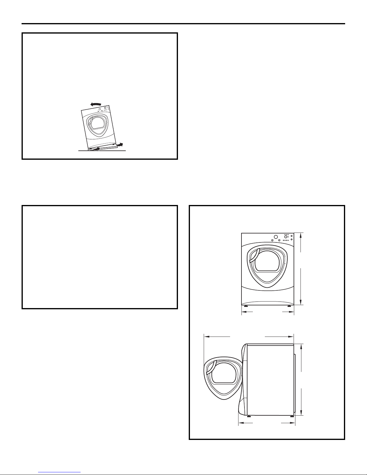
DRYER DIMENSIONS
Front View
27″
(68.6 cm)
53″
(134.6 cm)
39.5″
(100.3 cm)
39.5″
(100.3 cm)
Side View
33.5″
(85.1 cm)
14
Page 15
Installation Instructions
REQUIREMENTS FOR ALCOVE OR
CLOSET INSTALLATION
• Your dryer is approved for installation in
an alcove or closet, as stated on a label on
the dryer back.
• The dryer MUST be vented to the outdoors. See
the EXHAUSTING THE DRYER section.
• Minimum clearance between dryer cabinet and
adjacent walls or other surfaces is:
0″ either side
3″ front and rear
• Minimum vertical space from floor to overhead
shelves, cabinets, ceilings, etc., is 52″.
• Closet doors must be louvered or otherwise
ventilated and have at least 60 square inches
of open area equally distributed. If the closet
contains both a washer and a dryer, doors must
contain a minimum of 120 square inches of open
area equally distributed.
• The closet should be vented to the outdoors
to prevent gas pocketing in case of gas in the
supply line.
• No other fuel-burning appliance shall be
installed in the same closet with the dryer
(gas models only).
NOTE: WHEN THE EXHAUST DUCT IS LOCATED AT
THE REAR OF THE DRYER, MINIMUM CLEARANCE
FROM THE WALL IS 5.5 INCHES.
BATHROOM OR BEDROOM
INSTALLATION
• The dryer MUST be vented to the outdoors. See
EXHAUSTING THE DRYER.
• The installation must conform with local codes or,
in the absence of local codes, with the NATIONAL
ELECTRICAL CODE, ANSI/NFPA NO. 70 (for electric
dryers) or NATIONAL FUEL GAS CODE, ANSI Z223
(for gas dryers).
MOBILE OR MANUFACTURED HOME
INSTALLATION
• The installation must conform to the
MANUFACTURED HOME CONSTRUCTION & SAFETY
STANDARD, TITLE 24, PART 32–80 or, when such
standard is not applicable, with AMERICAN
NATIONAL STANDARD FOR MOBILE HOME,
NO. 501B.
• The dryer MUST be vented to the outdoors with
the termination securely fastened to the mobile
home structure. (See EXHAUSTING THE DRYER.)
• The vent MUST NOT be terminated beneath a
mobile or manufactured home.
• The vent duct material MUST BE METAL.
• FOR GAS MODELS ONLY: KIT 14-D346-33 MUST be
used to attach the dryer securely to the structure.
• FOR GAS MODELS ONLY: The vent MUST NOT be
connected to any other duct, vent or chimney.
• Do not use sheet metal screws or other
refastening devices which extend into the interior
of the exhaust vent.
• Provide an opening with a free area of at least
25 sq. in. for introduction of outside air into the
dryer room.
15
Page 16
Installation Instructions
CONNECTING A GAS DRYER (skip for electric dryers)
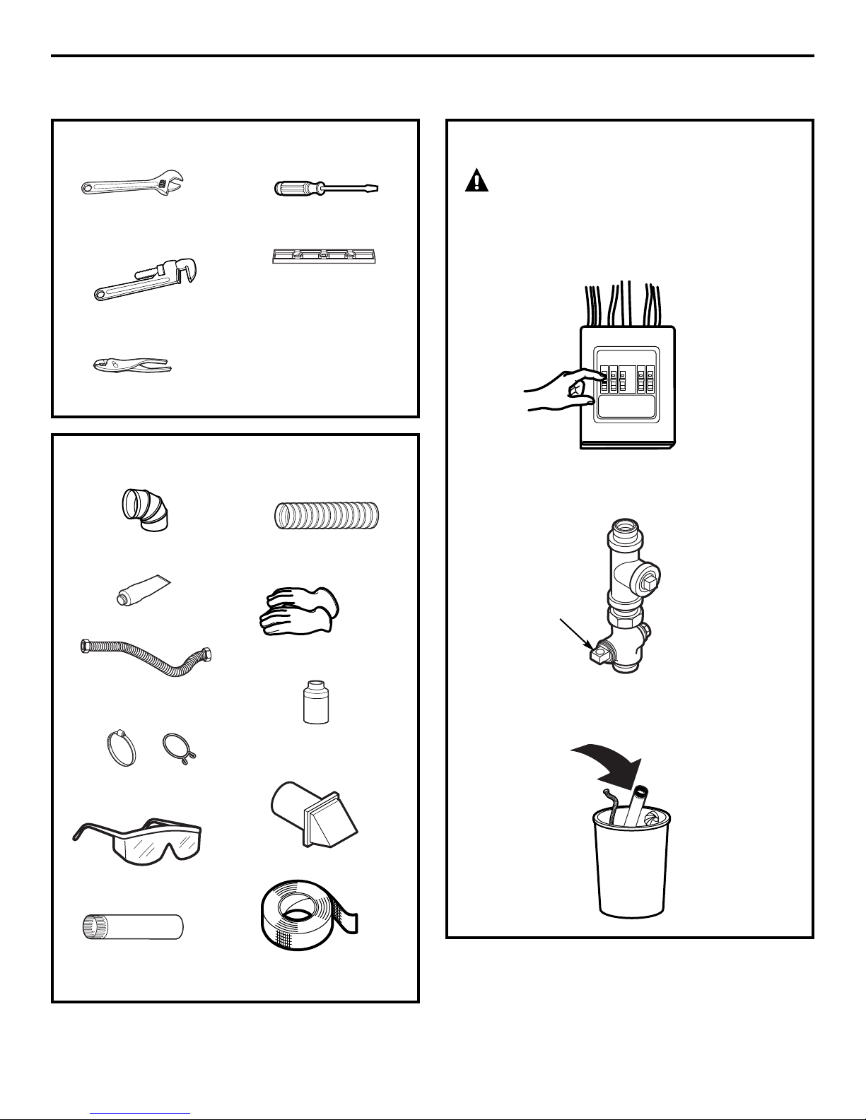
TOOLS YOU WILL NEED
❒ 10″ Adjustable
wrenches (2)
❒ 8″ Pipe wrench
❒ Slip joint pliers
❒ Flat-blade screwdriver
❒ Level
MATERIALS YOU WILL NEED
❒ 4″ dia. metal elbow
❒ 4″ dia., UL-listed flexible
metal duct (if needed)
FOR YOUR SAFETY:
WARNING
Before beginning the installation, turn off the circuit
breaker(s) or remove the dryer’s circuit fuse(s) at the
electrical box. Be sure the dryer cord is unplugged
from the wall.
Turn the dryer’s gas shutoff valve in the supply line
to the OFF position.
❒ Pipe compound
❒ Flexible gas line
connector
❒ Duct clamps (2) or
Spring clamps (2)
❒ Safety glasses
❒ 4″ dia. metal duct
(recommended)
Shutoff
Valve
❒ Gloves
Disconnect and discard old flexible gas connector
and ducting material.
❒ Soap solution for
leak detection
❒ Exhaust hood
❒ Duct tape
16
Page 17
Installation Instructions
GAS REQUIREMENTS
WARNING
• Installation must conform to local codes
and ordinances or, in their absence, the
NATIONAL FUEL GAS CODE, ANSI Z223.
• This gas dryer is equipped with a Valve and
Burner Assembly for use only with natural gas.
Using conversion kit 14-A048, your local service
organization can convert this dryer for use with
propane (LP) gas. ALL CONVERSIONS MUST BE
MADE BY PROPERLY TRAINED AND QUALIFIED
PERSONNEL AND IN ACCORDANCE WITH LOCAL
CODES AND ORDINANCE REQUIREMENTS.
• The dryer must be disconnected from the gas
supply piping system during any pressure testing
of that system at a test pressure in excess of
0.5 PSI (3.4 KPa).
• The dryer must be isolated from the gas supply
piping system by closing the equipment shut-off
valve during any pressure testing of the gas
supply piping of test pressure equal to or less
than 0.5 PSI (3.4KPa).
DRYER GAS SUPPLY CONNECTION
GAS SUPPLY
• A 1/8″ National Pipe Taper thread plugged
tapping, accessible for test gauge connection,
must be installed immediately upstream of the
gas supply connection to the dryer. Contact your
local gas utility should you have questions on the
installation of the plugged tapping.
• Supply line is to be 1/2″ rigid pipe and equipped
with an accessible shutoff within 6 feet of, and in
the same room with, the dryer.
• Use pipe thread compound appropriate for
natural or LP gas or use Teflon
• Connect flexible metal connector to dryer and
gas supply.
®
tape.
IN THE COMMONWEALTH
OF MASSACHUSETTS
• This product must be installed by a licensed
plumber or gas fitter.
• When using ball-type gas shut-off valves, they
shall be the T-handle type.
• A flexible gas connector, when used, must not
exceed 3 feet.
2″
(5.1 cm)
25⁄8″ (6.7 cm)
3/8″ NPT MALE THREAD GAS SUPPLY
NOTE: Add to vertical
dimension the distance between
cabinet bottom to floor.
ADJUSTING FOR ELEVATION
• Gas clothes dryers input ratings are based on
sea level operation and need not be adjusted
for operation at or below 2000 ft. elevation.
For operation at elevations above 2000 ft., input
ratings should be reduced at a rate of 4 percent
for each 1000 ft. above sea level.
• Installation must conform to local codes and
ordinances or, in their absence, the NATIONAL
FUEL GAS CODE, ANSI Z223.
17
Page 18

Installation Instructions
CONNECTING A GAS DRYER (cont.)
CONNECTING THE DRYER
TO THE GAS SUPPLY
Install a female 3/8″ NPT elbow at the end
A
of the dryer gas inlet.
Install a 3/8″ flare union adapter to the female
elbow.
IMPORTANT: Use a pipe wrench to securely hold
on to the end of the dryer gas inlet to prevent
twisting the inlet.
NOTE: Apply pipe compound or Teflon
the threads of the adapter and dryer gas inlet.
New Metal
Flexible Gas
Line Connector
Adapter
Elbow
Items not supplied
3/8″ NPT
®
Adapter
1/8″ NPT
Pipe Plug for
Checking Gas
Inlet Pressure
Shut-Off Valve
Pipe size at
least 1/2″
tape to
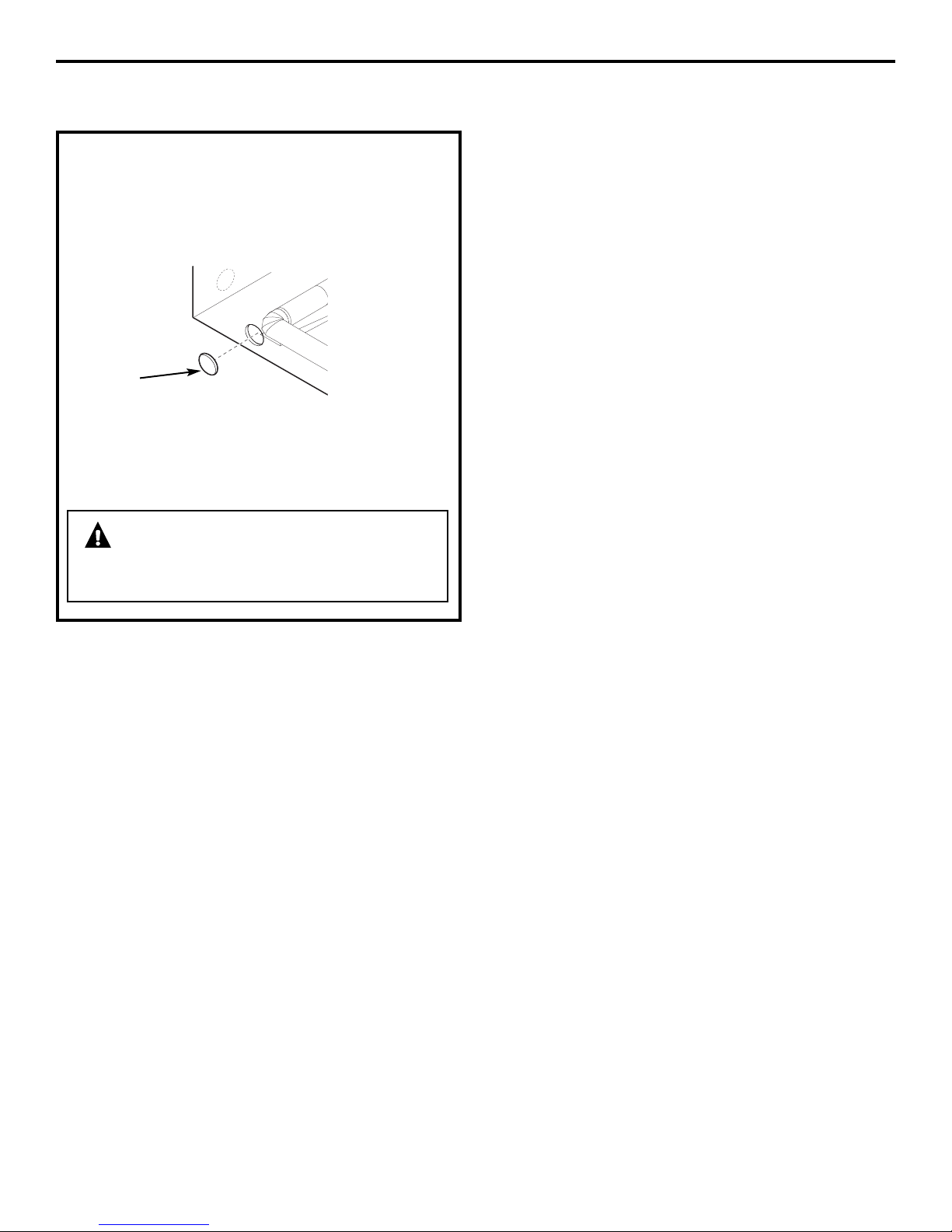
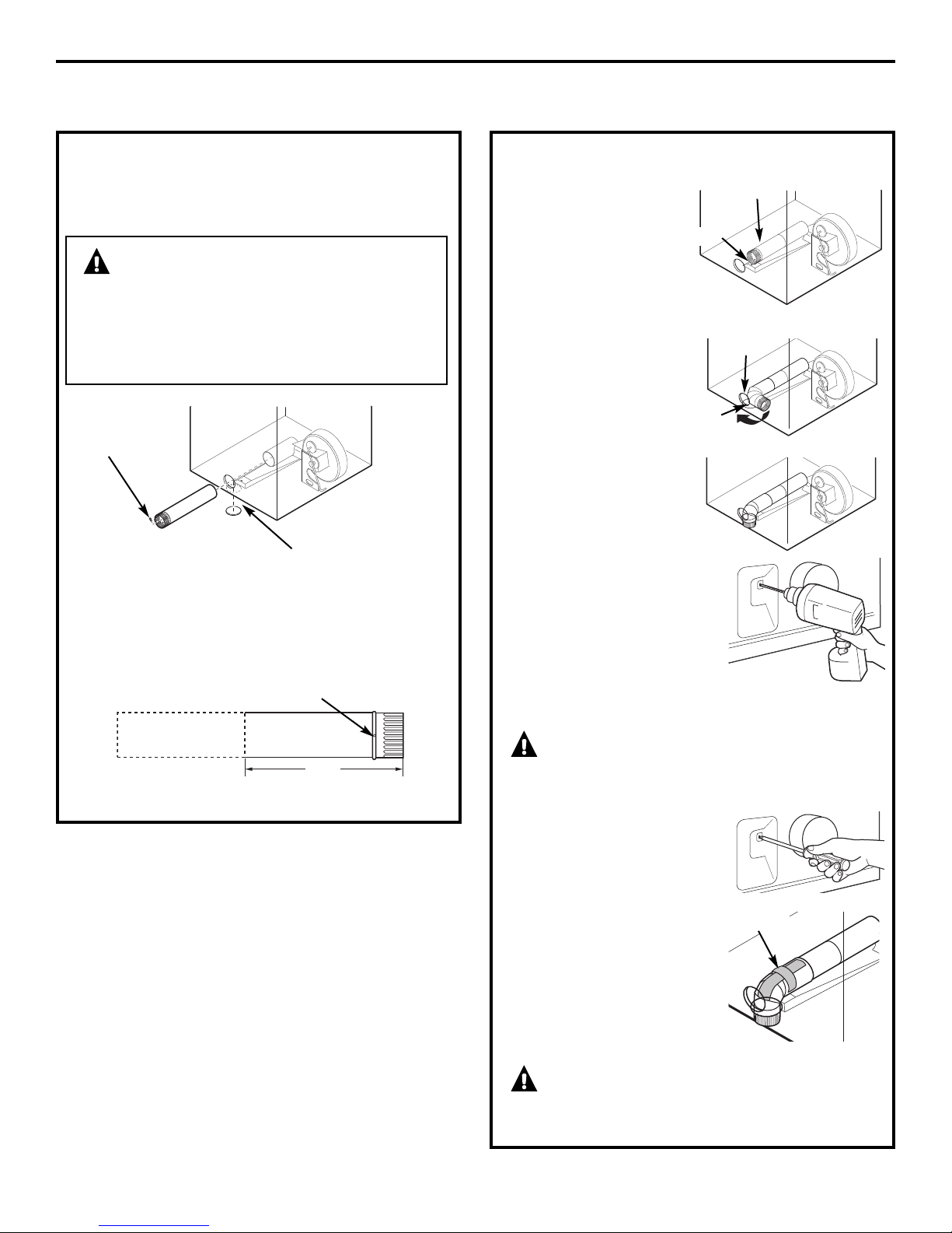
CONNECTING THE DRYER
TO THE GAS SUPPLY (cont.)
Install a 1/8″ NPT plugged tapping to the dryer
D
gas line shut-off valve for checking gas inlet
pressure.
Install a flare union adapter to the plugged
tapping.
NOTE: Apply pipe compound or Teflon
the threads of the adapter and plugged tapping.
Apply pipe compound or
Teflon
threads.
®
tape to all male
Shut-off Valve
Plugged
Tapping
®
tape to
Attach the flexible metal gas line connector to
B
the adapter.
Apply pipe compound to the
adapter and dryer gas inlet.
Tighten the flexible gas line connection, using
C
two adjustable wrenches.
Tighten all connections, using two adjustable
E
wrenches. Do not overtighten.
Open the gas shutoff valve.
F
18
Page 19

Installation Instructions
TEST FOR LEAKS
WARNING – Never use an
open flame to test for gas leaks.
Check all connections for leaks with soapy solution
or equivalent.
Apply a soap solution. The leak test solution must
not contain ammonia, which could cause damage
to the brass fittings.
If leaks are found, close the valve, retighten the joint
and repeat the soap test.
Open Gas
Valve
ELECTRICAL REQUIREMENTS
FOR GAS DRYERS
This appliance must be supplied with 120V, 60Hz,
and connected to a properly grounded branch
circuit, protected by a 15- or 20-amp circuit
breaker or time-delay fuse.
If electrical supply provided does not meet
the above specifications, it is recommended that
a licensed electrician install an approved outlet.
WARNING – This dryer is equipped
with a three-prong (grounding) plug for your
protection against shock hazard and should be
plugged directly into a properly grounded threeprong receptacle. Do not cut or remove the
grounding terminal from this plug.
ELECTRICAL CONNECTION
INFORMATION FOR GAS DRYERS
WARNING – To reduce the risk of
fire, electrical shock and personal injury:
• Do not use an extension cord or an adapter plug
with this appliance.
• The dryer must be electrically grounded in
accordance with local codes and ordinances
or, in the absence of local codes, in accordance
with the NATIONAL ELECTRICAL CODE, ANSI/NFPA
NO. 70.
Ensure proper
ground exists
before use.
If local codes permit, an external ground wire (not
provided), which meets local codes, may be added
by attaching to the green ground screw on the rear
of the dryer, and to an alternate established ground.
Ensure proper ground exists before use.
Ground
Screw
19
Page 20
Installation Instructions
CONNECTING AN ELECTRIC DRYER (skip for gas dryers)
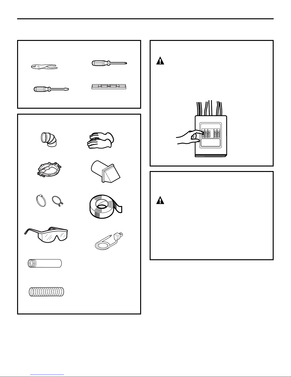
TOOLS YOU WILL NEED
❒ Slip joint pliers
❒ Flat-blade screwdriver
❒ Phillips screwdriver
❒ Level
MATERIALS YOU WILL NEED
❒ 4″ dia. metal elbow
❒ 3/4″ strain relief
(UL recognized)
❒ Gloves
❒ Exhaust hood
FOR YOUR SAFETY:
WARNING
Before making the electrical connection, turn off
the circuit breaker(s) or remove the dryer’s circuit
fuse(s) at the electrical box. Be sure the dryer cord
is unplugged from the wall. NEVER LEAVE THE
ACCESS COVER OFF THE TERMINAL BLOCK.
ELECTRICAL CONNECTION
INFORMATION FOR ELECTRIC DRYERS
❒ 4″ duct clamps (2) or
4″ spring clamps (2)
❒ Safety glasses
❒ 4″ dia. metal duct
(recommended)
❒ 4″ dia., UL-listed flexible
metal duct (if needed)
❒ Duct tape
❒ Dryer power cord kit
(not provided with dryer)
UL rated 120/240V,
30A with 3 or 4 prongs.
Identify the plug type as
per the house receptacle
before purchasing line cord.
WARNING – To reduce the risk of
fire, electrical shock and personal injury:
• Do not use an extension cord or an adapter plug
with this appliance.
• The dryer must be electrically grounded in
accordance with local codes and ordinances
or, in the absence of local codes, in accordance
with the NATIONAL ELECTRICAL CODE,
ANSI/NFPA NO. 70.
20
Page 21
Installation Instructions
ELECTRICAL REQUIREMENTS
FOR ELECTRIC DRYERS
This dryer must be connected to an individual
branch circuit, protected by the required timedelay fuses or circuit breakers. A three- or fourwire, single phase, 120/240V or 120/208V, 60Hz,
30-amp circuit is required.
If the electric supply does not meet the above
specifications, then call a licensed electrician.
GROUNDING INSTRUCTIONS
This dryer must be connected to a grounded metal,
permanent wiring system, or an equipmentgrounding conductor must be run with the circuit
conductors and connected to the equipment
grounding terminal on the appliance.
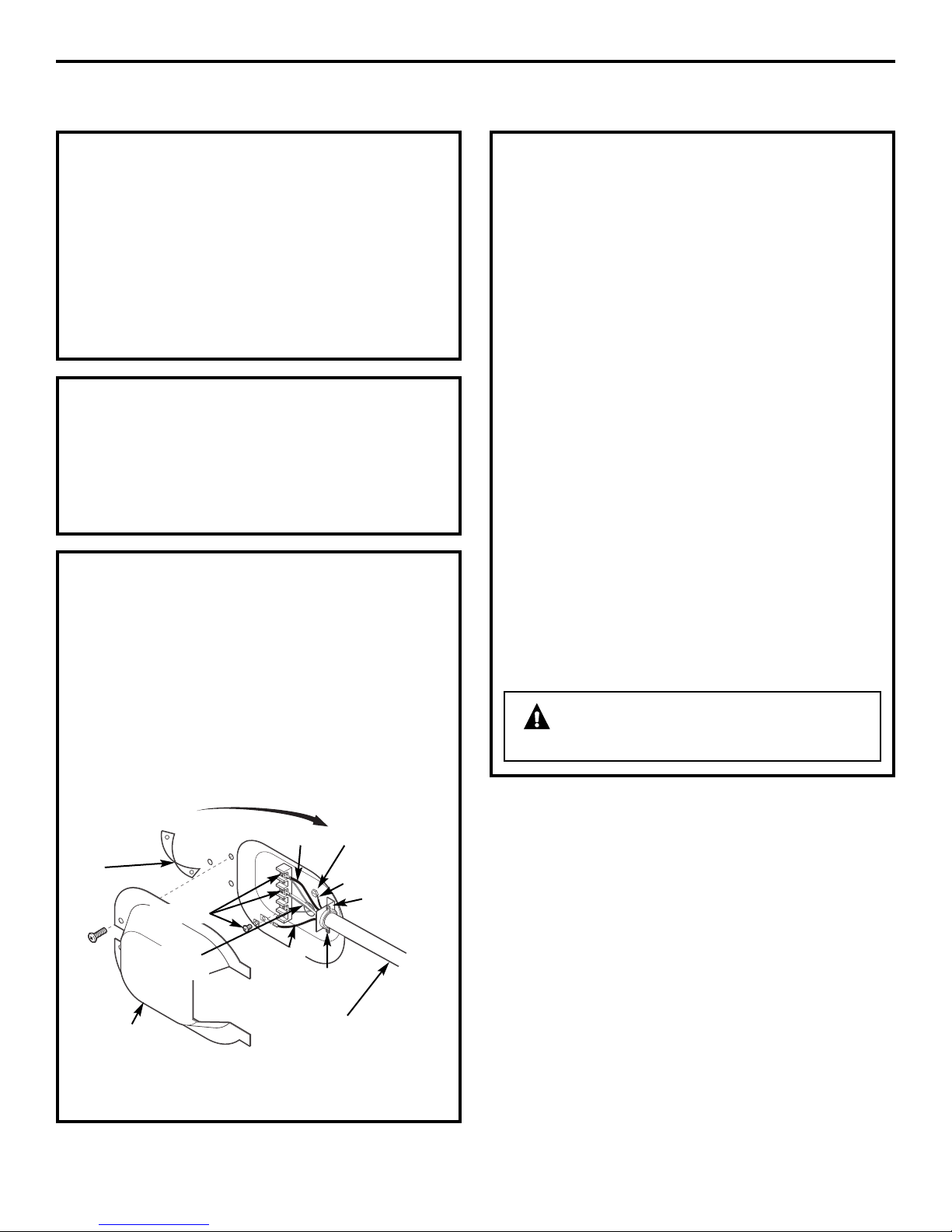
CONNECTING DRYER USING 4-WIRE
CONNECTION (MUST BE USED FOR
MOBILE HOME INSTALLATION)
NOTE: Since January 1, 1996, the National Electrical
Code requires that new constructions utilize a
4-wire connection to an electric dryer. A 4-wire cord
must also be used where local codes do not permit
grounding through the neutral.
3-wire connection is NOT for use on new
construction.
Remove ground
strap and
discard. Keep
green ground
screw
Hot Wire
Screws (3)
Relocate green ground
screw here
Green Wire
Strain Relief
Bracket
CONNECTING DRYER USING 4-WIRE
CONNECTION (MUST BE USED FOR
MOBILE HOME INSTALLATION) (cont.)
1. Turn off the circuit breaker(s) (30 amp) or remove
the dryer’s circuit fuse at the electrical box.
2. Be sure the dryer cord is unplugged from the wall
receptacle.
3. Remove the power cord cover located at the
lower back.
4. Remove and discard ground strap. Keep the
green ground screw for step 7.
5. Install 3/4 in. UL-recognized strain relief to power
cord entry hole. Bring power cord through strain
relief.
6. Connect power cord as follows:
A. Connect the 2 hot lines to the outer screws
of the terminal block (marked L1 and L2).
B. Connect the neutral (white) line to the center
of the terminal block (marked N).
7. Attach ground wire of power cord with the green
ground screw (hole above strain relief bracket).
Tighten all terminal block screws (3) completely.
8. Properly secure power cord to strain relief.
9. Reinstall the cover.
WARNING – NEVER LEAVE THE
COVER OFF OF THE TERMINAL BLOCK.
Neutral
(white)
Cover
Hot Wire
3/4″ UL Recognized
Strain Relief
4 #10 AWG minimum copper
conductors or 120/240V 30A power
supply cord kit marked for use with
dryers and provided with closed loop
or spade terminals with upturned ends
(not supplied)
21
Page 22
Installation Instructions
CONNECTING AN ELECTRIC DRYER (cont.)
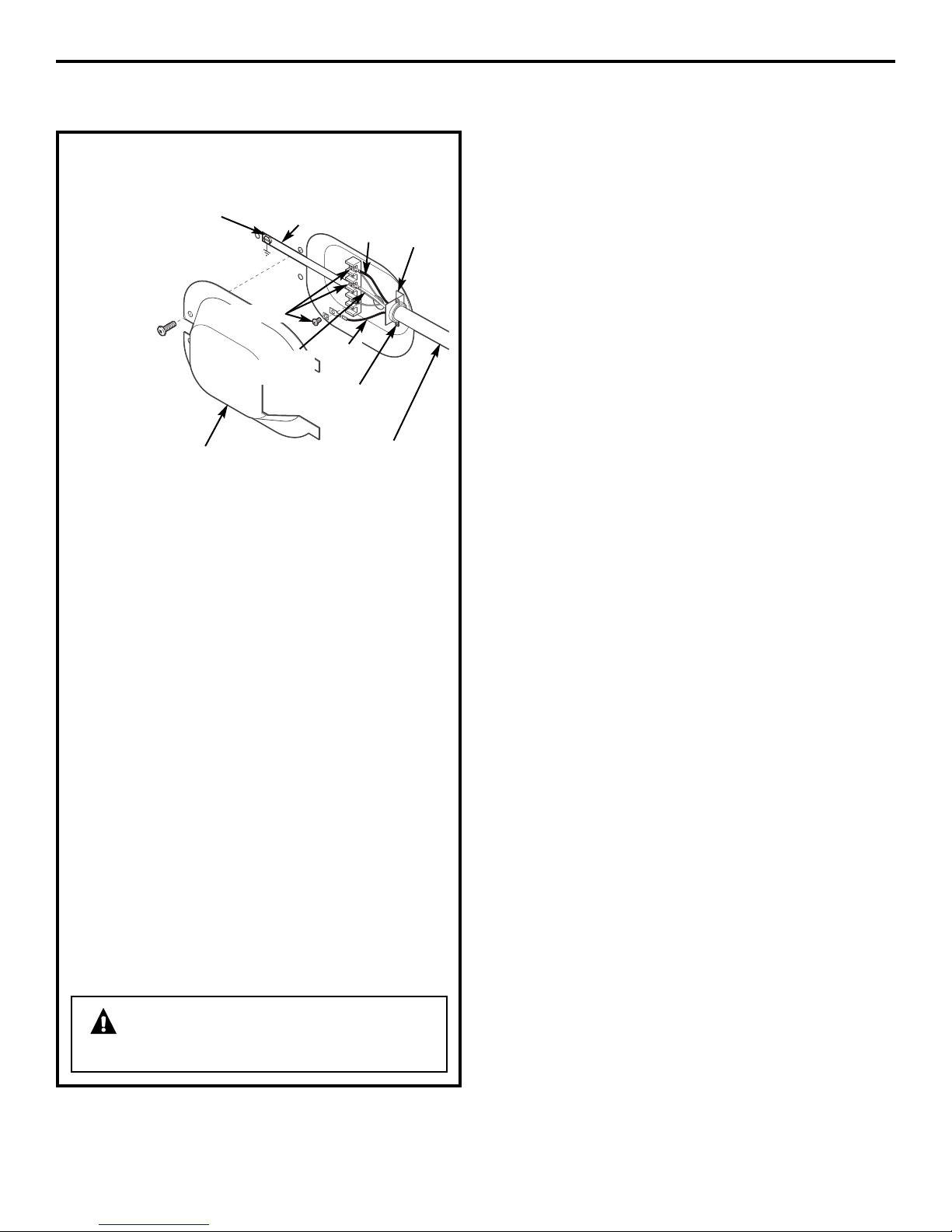
CONNECTING DRYER USING 3-WIRE
CONNECTION
If required, by
local code,
install external
ground (not
provided) to
grounded
metal, cold
water pipe,
or other
established
ground
determined
by a qualified
electrician.
Green Ground
Screw
Screws (3)
Cover
Ground
Strap
Hot Wire
Neutral
(white)
3 #10 AWG minimum copper
conductors or 120/240V 30A power
supply cord kit marked for use with
dryers and provided with closed loop
or spade terminals with upturned ends
(not supplied)
Hot
Wire
3/4″ UL
Recognized
Strain Relief
Strain
Relief
Bracket
1. Turn off the circuit breaker(s) (30 amp) or remove
the dryer’s circuit fuse at the electrical box.
2. Be sure the dryer cord is unplugged from the
wall receptacle.
3. Remove the power cord cover located at the
lower back.
4. Install 3/4 in. UL-recognized strain relief to power
cord entry hole. Bring power cord through strain
relief.
5. Connect power cord as follows:
A. Connect the 2 hot lines to the outer screws
of the terminal block (marked L1 and L2).
B. Connect the neutral (white) line to the center
of the terminal block (marked N).
6. Be sure ground strap is connected to neutral
(center) terminal of block and to green ground
screw on cabinet rear. Tighten all terminal block
screws (3) completely.
7. Properly secure power cord to strain relief.
8. Reinstall the cover.
WARNING – NEVER LEAVE THE
COVER OFF OF THE TERMINAL BLOCK.
22
Page 23
Installation Instructions
EXHAUSTING THE DRYER
WARNING – To reduce the
risk of fire or personal injury:
• This clothes dryer must be exhausted to the outdoors.
″
• Use only 4
exhaust duct.
• Use only 4
(semi-rigid or foil-type) duct to connect the dryer
to the home exhaust duct. It must be installed
in accordance with the instructions found in
“Connecting the Dryer to House Vent” on page 24
of this manual.
• Do not terminate exhaust in a chimney, a wall, a
ceiling, gas vent, crawl space, attic, under an
enclosed floor, or in any other concealed space of
a building.
• Never terminate the exhaust into a common duct
with a kitchen exhaust system. A combination of
grease and lint creates a potential fire hazard.
• Do not use duct longer than specified in the exhaust
length table. Longer ducts can accumulate lint,
creating a potential fire hazard.
• Never install a screen in or over the exhaust duct.
This will cause lint to accumulate, creating a
potential fire hazard.
• Do not assemble ductwork with any fasteners that
extend into the duct. These fasteners can
accumulate lint, creating a potential fire hazard.
• Do not obstruct incoming or exhausted air.
• Provide an access for inspection and cleaning of
the exhaust system, especially at turns and joints.
Exhaust system shall be inspected and cleaned at
least once a year.
• This dryer comes ready for rear exhausting. If space
is limited, use the instructions on pages 28–31 to
exhaust directly from the sides or bottom of the
cabinet.
rigid metal ducting for the home
″
rigid metal or UL-listed flexible metal
EXHAUST SYSTEM CHECKLIST
HOOD OR WALL CAP
• Terminate in a manner to prevent back drafts or
entry of birds or other wildlife.
• Termination should present minimal resistance to
the exhaust airflow and should require little or no
maintenance to prevent clogging.
• Never install a screen in or over the exhaust duct.
• Wall caps must be installed at least 12″ above
ground level or any other obstruction with the
opening pointed down.
SEPARATION OF TURNS
• For best performance, separate all turns by
at least 4 ft. of straight duct, including distance
between last turn and dampened wall cap.
For turns less than 4 ft. apart, see the Ducting
Component Equivalency Chart.
SEALING OF JOINTS
• All joints should be tight to avoid leaks. The male
end of each section of duct must point away
from the dryer.
• Do not assemble the ductwork with fasteners
that extend into the duct. They will serve as
a collection point for lint.
• Duct joints should be made air- and
moisture-tight by wrapping the overlapped
joints with duct tape or aluminum tape.
• Horizontal runs should slope down towards
outdoors 1/4″ per foot.
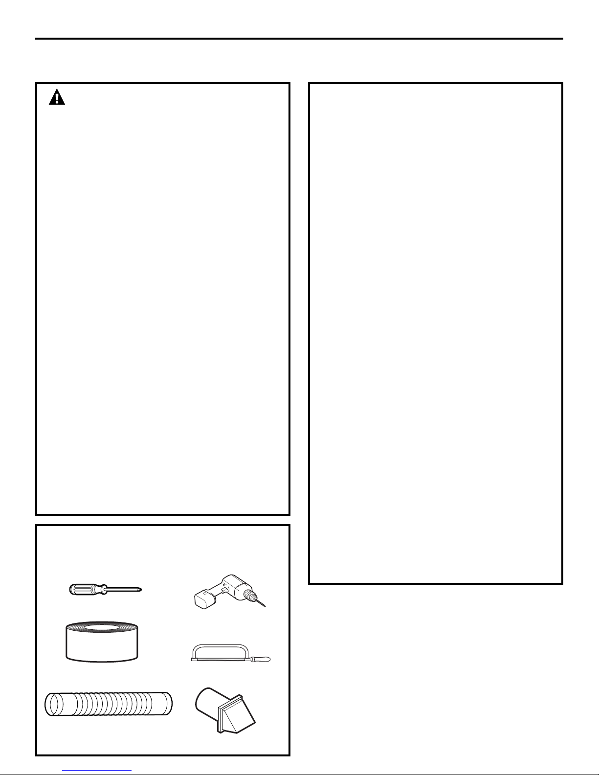
TOOLS AND MATERIALS YOU WILL
NEED TO INSTALL EXHAUST DUCT
❒ Phillips-head screwdriver
❒ Drill with 1/8″ drill bit
(for bottom venting)
❒ Duct tape or duct clamp
❒ Rigid or UL-listed flexible
metal 4″ (10.2 cm) duct
❒ Hacksaw
❒ Vent hood
INSULATION
• Ductwork that runs through an unheated area
or is near air conditioning should be insulated
to reduce condensation and lint buildup.
23
Page 24
Installation Instructions
EXHAUSTING THE DRYER (cont.)
CONNECTING THE DRYER TO
HOUSE VENT
RIGID METAL TRANSITION DUCT
• For best drying performance, a rigid metal
transition duct is recommended.
• Rigid metal transition ducts reduce the risk of
crushing and kinking.
UL-LISTED FLEXIBLE METAL (SEMI-RIGID)
TRANSITION DUCT
• If rigid metal duct cannot be used, then UL-listed
flexible metal (semi-rigid) ducting can be used
(Kit WX08X10077).
• Never install flexible metal duct in walls, ceilings,
floors or other enclosed spaces.
• Total length of flexible metal duct should not
exceed 8 feet (2.4 m).
• For many applications, installing elbows at both
the dryer and the wall is highly recommended (see
illustrations at right). Elbows allow the dryer to sit
close to the wall without kinking and/or crushing
the transition duct, maximizing drying performance.
• Avoid resting the duct on sharp objects.
UL-LISTED FLEXIBLE METAL (FOIL-TYPE)
TRANSITION DUCT
• In special installations, it may be necessary to
connect the dryer to the house vent using a flexible
metal (foil-type) duct. A UL-listed flexible metal
(foil-type) duct may be used ONLY in installations
where rigid metal or flexible metal (semi-rigid)
″
ducting cannot be used AND where a 4
can be maintained throughout the entire length
of the transition duct.
• In Canada and the United States, only the flexible
metal (foil-type) ducts that comply with the “Outline
for Clothes Dryer Transition Duct, Subject 2158A”
shall be used.
• Never install flexible metal duct in walls, ceilings,
floors or other enclosed spaces.
• Total length of flexible metal duct should not
exceed 8 feet (2.4 m).
• Avoid resting the duct on sharp objects.
• For best drying performance:
1. Slide one end of the duct over the clothes
dryer outlet pipe.
2. Secure the duct with a clamp.
3. With the dryer in its permanent position,
extend the duct to its full length. Allow 2
duct to overlap the exhaust pipe. Cut off and
remove excess duct. Keep the duct as straight
as possible for maximum airflow.
4. Secure the duct to the exhaust pipe with the
other clamp.
diameter
″
of
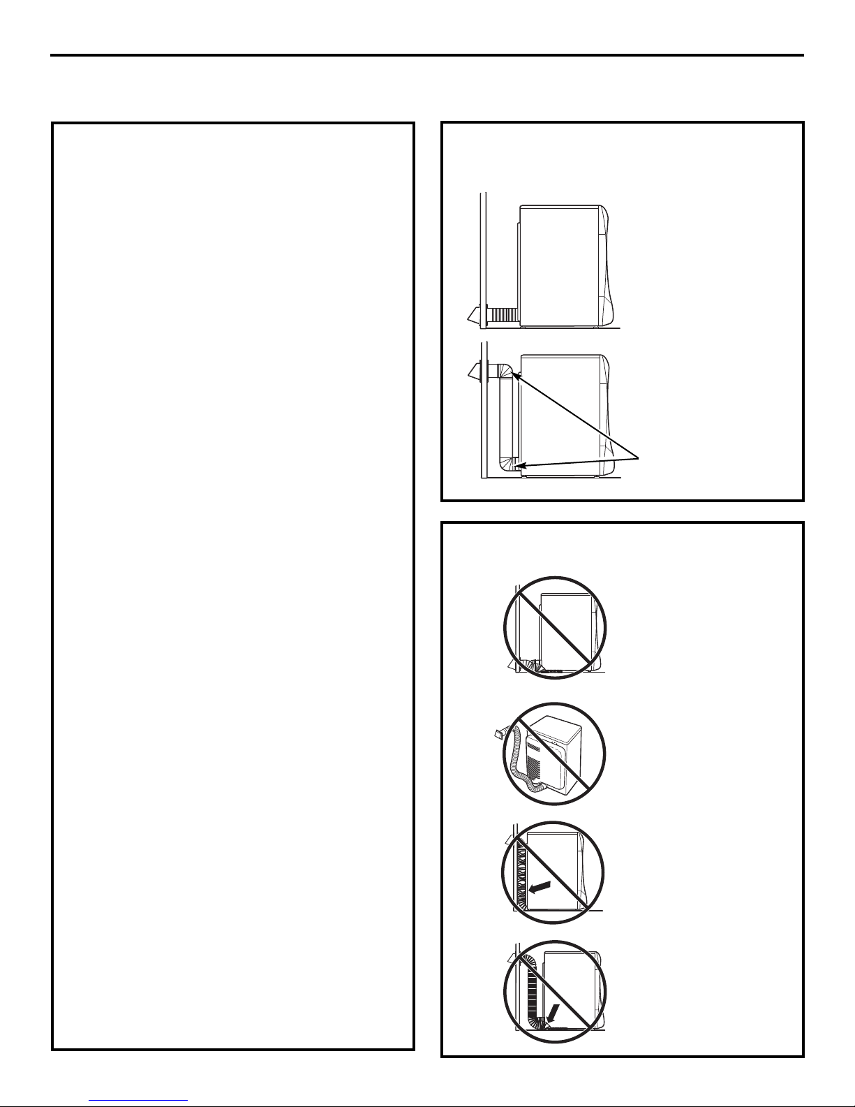
FOR TRANSITION VENTING
(DRYER TO WALL), DO:
•DO cut duct
as short as
possible and
install straight
into wall.
•DO use elbows
when turns are
necessary.
Elbows
DO NOT:
•DO NOT bend or
collapse ducting.
Use elbows if
turns are
necessary.
•DO NOT use
excessive
exhaust length.
Cut duct as short
as possible.
•DO NOT crush
duct against
the wall.
•DO NOT set
dryer on duct.
24
Page 25
Installation Instructions
WARNING
USE ONLY METAL DUCT 4″ DIAMETER (102 mm
FOR CANADA). DO NOT USE DUCT LONGER THAN
SPECIFIED IN THE EXHAUST LENGTH TABLE.
Ducting longer than 150 equivalent feet will:
• Increase the drying times and the energy cost.
• Reduce the dryer life.
• Accumulate lint, creating a potential fire hazard.
• Total length of flexible metal duct shall not exceed
7.9′ (2.4 m).
EXAMPLE ONLY
The following chart describes an example of one
possible ductwork installation.
EQUIVALENT
RIGID NUMBER EQUIVALENT
DUCT PIECES LENGTH X USED = LENGTH
Rigid Metal 1 Ft. X (4) = 4 Ft.
Ducting
(Preferred)
The correct exhaust installation is your
responsibility.
Problems due to incorrect installation are not
covered by the warranty.
The length of the exhaust system depends upon
the type of duct, number of turns and the type of
exhaust hood (wall cap), and all conditions noted
below.
For satisfactory air movement, the total duct length
should not exceed 150 equivalent feet.
DUCTING
TRANSITION
(DRYER TO WALL)
Less Than 4 Ft.
(WALL TO WALL CAP)
INSIDE WALLS/CEILING
CAPS
WALL
4≤
(10.2 cm)
Elbows 10 Ft. X (3) = 30 Ft.
(90°/45°)
Turns Less 2 Ft. X (1) = 2 Ft.
Than 4 Ft.
Rigid Ducting 1 Ft. X (5) = 5 Ft.
4″ Wall Cap 5 Ft. X (1) = 5 Ft.
Total Ductwork Length = 46 Ft.
TOTAL MUST BE LESS THAN OR EQUAL TO 150 FT.
25
Page 26
Installation Instructions
EXHAUSTING THE DRYER (cont.)
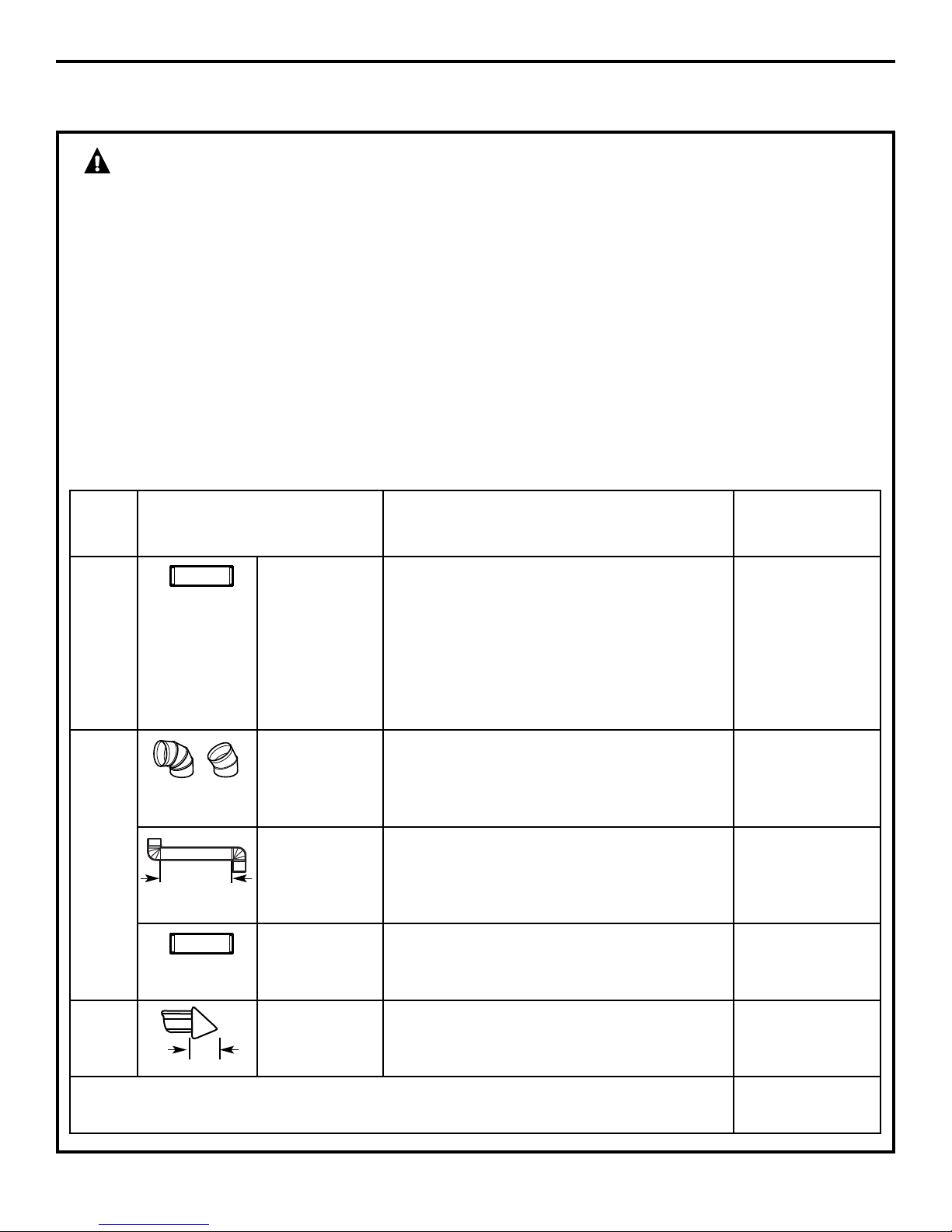
DUCTING COMPONENT EQUIVALENCY CHART
EQUIVALENT
RIGID NUMBER EQUIVALENT
DUCT PIECES LENGTH X USED = LENGTH
Rigid Metal 1 Ft. X ( ) = Ft.
Ducting
(Preferred)
UL-Listed,
Semi-Rigid 3 Ft. X ( ) = Ft.
Metal Ducting
(DRYER TO WALL)
TRANSITION DUCTING
(inside diameter
does not change)
Elbows (90°/45°) 10 Ft. X ( ) = Ft.
Less Than 4 Ft.
(WALL TO WALL CAP)
INSIDE WALLS/CEILING
WALL CAPS
Turns less 2 Ft. X ( ) = Ft.
Than 4 Ft.
Rigid Metal 1 Ft. X ( ) = Ft.
Ducting
4″ Wall Cap 5 Ft. X ( ) = Ft.
4≤
(10.2 cm)
Louvered Wall 10 Ft. X ( ) = Ft.
Cap
2.5″ Wall Cap 23 Ft. X ( ) = Ft.
2.5″
(6.35
cm)
Total Ductwork Length = Ft.
TOTAL MUST BE LESS THAN OR EQUAL TO 150 FT.
26
Page 27
Installation Instructions
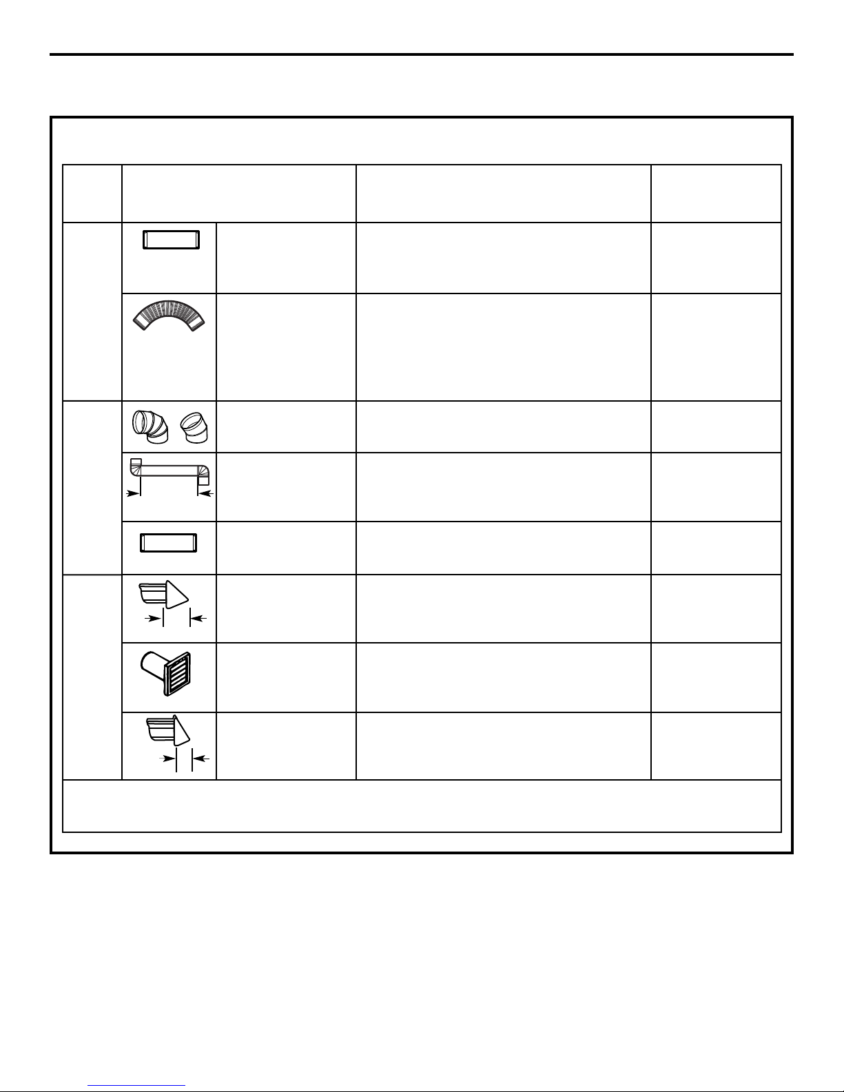
BEFORE YOU BEGIN
• Remove and discard existing plastic or metal foil
duct and replace with UL-listed duct.
• Remove any lint from the wall exhaust opening.
Wall
Internal
Duct
Opening
Check that exhaust
hood damper opens
and closes freely.
STANDARD REAR EXHAUST
We recommend that you install your
dryer before installing your washer. This
will permit direct access for easier exhaust
connection.
Slide the end of the exhaust duct on the back
of the dryer and secure with duct tape or a
hose clamp.
RECOMMENDED CONFIGURATION
TO MINIMIZE EXHAUST BLOCKAGE
Using duct elbows will prevent duct kinking and
collapsing.
Transition
Ducting
Duct
NOTE: We strongly recommend using rigid metal
exhaust duct.
• For straight-line installation, connect the dryer
exhaust to the wall, using duct tape.
Wall Side
Dryer
Side
27
Page 28
Installation Instructions
EXHAUSTING THE DRYER (cont.)
SIDE VENTING:
Dryer Exhaust to right of cabinet for Electric
models only.
Dryer Exhaust to left of cabinet for Gas and
Electric models.
WARNING – BEFORE PERFORMING
THIS EXHAUST INSTALLATION, BE SURE TO
DISCONNECT THE DRYER FROM ITS ELECTRICAL
SUPPLY. PROTECT YOUR HANDS AND ARMS
FROM SHARP EDGES WHEN WORKING INSIDE
THE CABINET. BE SURE TO WEAR GLOVES.
Remove
screw
and save
Right
Left
Bottom
Remove desired
knockout (one only)
ADDING A NEW DUCT
Fixing hole
Left side
exhaust
Reconnect the cut portion (A) of the duct to the
blower housing. Make sure that the shortened duct
is aligned with the tab in the base. Use the screw
saved previously to secure the duct in place
through the tab on the appliance base.
Portion “A”
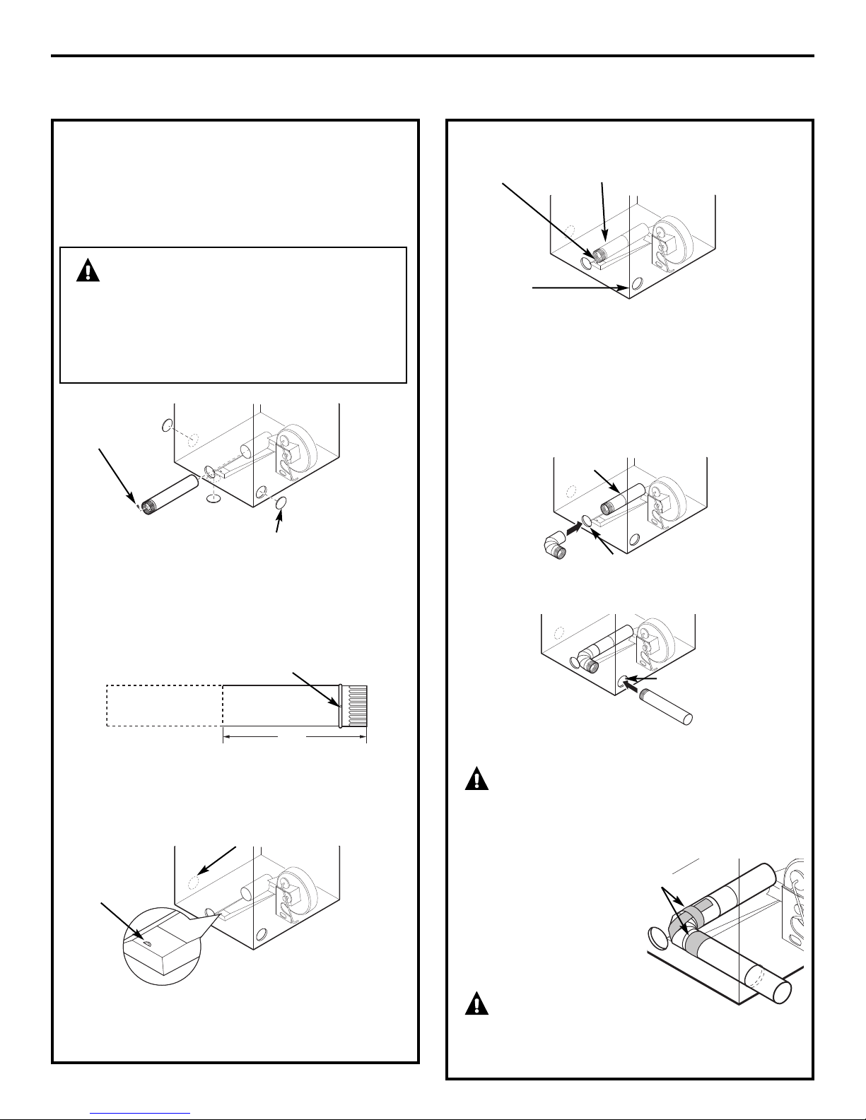
ADDING ELBOW AND DUCT FOR EXHAUST
TO LEFT OR RIGHT SIDE OF CABINET
Internal duct
Rear opening
Detach and remove the bottom, right or left side
knockout as desired. Remove the screw inside the
dryer exhaust duct and save. Pull the duct out of
the dryer.
Fixing hole
A
133⁄8″
Cut the duct as shown and keep portion A.
TAB LOCATION
Not for gas
Bend tab
up 45°
• Insert the 4″ elbow through the rear opening and
connect the elbow to the dryer internal duct.
Side opening
• Insert the 4″ duct through the side opening
and connect it to the elbow.
CAUTION: Be sure not to pull or
damage the electrical wires inside the dryer
when inserting the duct. A slight interference
may occur between the exhaust and the wire
components.
• Apply duct tape as
shown on the joint
between the dryer
internal duct and
the elbow, and also
the joint between the
elbow and the side duct.
Duct tape
Through the rear opening, locate the tab in the
middle of the appliance base. Lift the tab to about
45°, using a flat blade screwdriver.
CAUTION:
Internal duct joints must be secured with tape;
otherwise, they may separate and cause a
safety hazard.
28
Page 29
Installation Instructions
SIDE VENTING (cont.)
ADDING COVER PLATE TO REAR OF CABINET
(SIDE EXHAUST)
Plate
(Kit WE1M454)
Connect standard metal elbows and ducts to
complete the exhaust system. Cover back opening
with a plate (Kit WE1M454) available from your
local service provider. Place dryer in final location.
WARNING – NEVER LEAVE
THE BACK OPENING WITHOUT THE PLATE.
(Kit WE1M454)
29
Page 30
Installation Instructions
EXHAUSTING THE DRYER (cont.)
BOTTOM VENTING:
Dryer Exhaust to the bottom of cabinet
for Gas and Electric models.
WARNING – BEFORE PERFORMING
THIS EXHAUST INSTALLATION, BE SURE TO
DISCONNECT THE DRYER FROM ITS ELECTRICAL
SUPPLY. PROTECT YOUR HANDS AND ARMS
FROM SHARP EDGES WHEN WORKING INSIDE
THE CABINET. BE SURE TO WEAR GLOVES.
Remove
screw
and save
Bottom
Remove desired
knockout (one only)
Remove the screw inside the dryer exhaust duct
and save. Pull the duct out of the dryer. Detach
and remove the bottom knockout .
Fixing hole
A
123⁄8″
Cut the duct as shown and keep portion A.
ADDING A NEW DUCT
• Reconnect the cut
portion A of the
duct to the blower
housing.
• Tape the elbow
in a 90 degree
position to
prevent rotation.
• Insert the elbow
through the rear hole
and connect it to
portion A. Rotate
the elbow through
the bottom opening.
• While holding down
the pipe and elbow, using
your hand through the rear
opening, drill a 1/8″ hole
through the bottom tab
hole and the pipe as
shown in the illustration.
NOTE: Make sure the hole is drilled all the way
through the elbow and pipe.
Fixing hole
Portion “A”
Rear hole
Bottom
opening
Bottom view
CAUTION: Be sure not to pull or
damage the electrical wires inside the dryer
when inserting the duct.
• While still holding down
the pipe and elbow from
the rear opening, screw
the pipes in place with
the previously saved screw.
• Apply duct tape
as shown on the joint
between the dryer internal
duct and the elbow.
NOTE: Make sure the tape
covers the screw hole in
portion A where it connects
to the elbow.
Duct tape
CAUTION: Internal duct joints must be
secured with tape; otherwise, they may separate
and cause a safety hazard.
30
Page 31

Installation Instructions
BOTTOM VENTING (cont.)
Dryer Exhaust to the bottom of cabinet
for Gas and Electric models.
ADDING COVER PLATE TO REAR OF CABINET
(BOTTOM EXHAUST)
Plate
(Kit WE1M454)
Connect standard metal elbows and ducts to
complete the exhaust system. Cover back opening
with a plate (Kit WE1M454) available from your
local service provider. Place dryer in final location.
WARNING – NEVER LEAVE
THE BACK OPENING WITHOUT THE PLATE.
(Kit WE1M454)
31
Page 32

FINAL SETUP
Installation Instructions
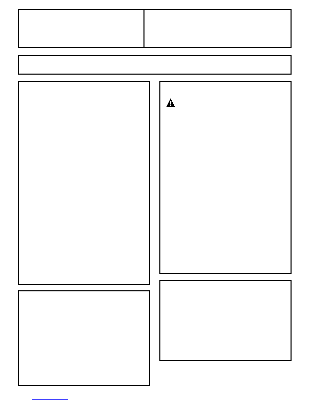
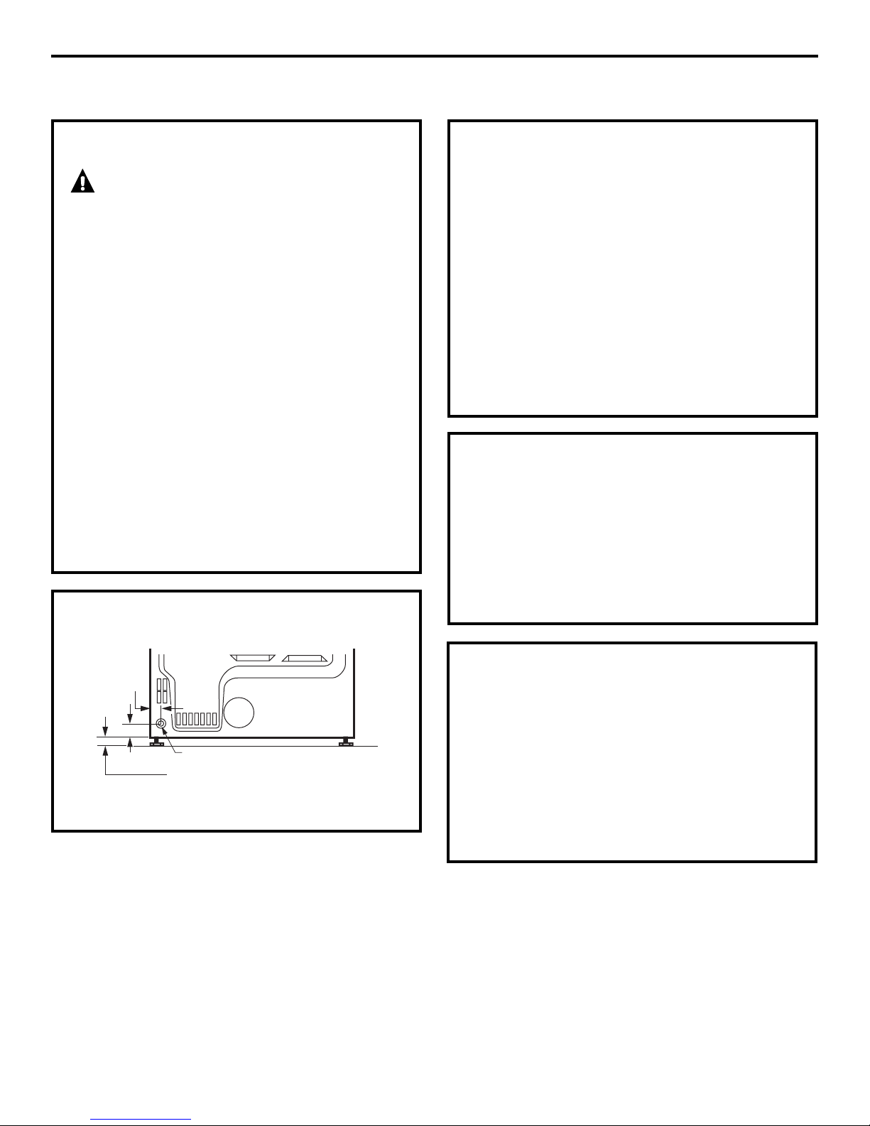
1
LEVEL THE DRYER
Stand the dryer upright near the final location and
adjust the four leveling legs at the corners to ensure
that the dryer is level from side to side and front
to rear.
Raise
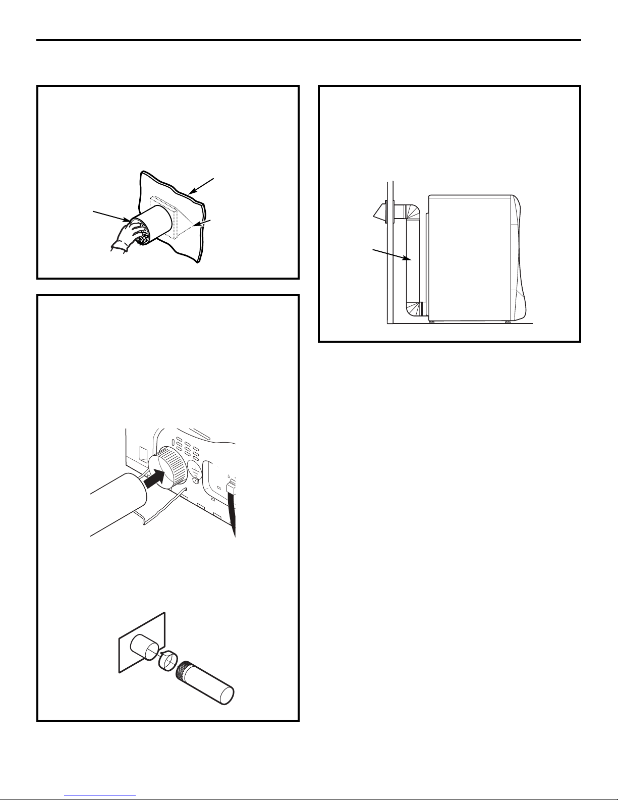
2
ATTACH SERIAL CABLE
Attach the serial cable for washer and dryer
connection to the serial port on the back of
the dryer.
Lower
3
PLUG DRYER IN
Ensure proper
ground exists
before use.
GROUNDING INSTRUCTIONS
4
This appliance must be grounded. In the event
of malfunction or breakdown, grounding will
reduce the risk of electric shock by providing
a path of least resistance for electric current.
This appliance is equipped with a cord having an
equipment-grounding conductor and a grounding
plug. The plug must be plugged into an appropriate
outlet that is properly installed and grounded in
accordance with all local codes and ordinances.
Attach the other end of the cable to the washer
before pushing the washer into its final position.
Serial Port
Rear of
Dryer
32
Page 33

4
DRYER STARTUP
Installation Instructions
SERVICING
Press the POWER button.
NOTE: If the dryer has been exposed to
temperatures below freezing for an extended period
of time, allow it to warm up before pressing
POWER. Otherwise, the display will not come on.
The dryer is now ready for use.
WARNING – Label all wires prior
to disconnection when servicing controls. Wiring
errors can cause improper and dangerous
operation after servicing/installation.
For replacement parts and other information,
refer to the back cover for servicing phone
numbers.
33
Page 34

Installation Instructions
REVERSING THE DOOR SWING (if desired)
IMPORTANT NOTES
• Read the instructions all the way through before
starting.
• Handle parts carefully to avoid scratching paint.
• Provide a non-scratching work surface for
the doors.
• Set screws down by their related parts to avoid
using them in the wrong places.
• All screws must be hand-tightened.
• Normal completion time to reverse the door
swing is 30–60 minutes.
IMPORTANT: Once you begin, do not move the
cabinet until door-swing reversal is completed.
These instructions are for changing the hinges
from the right side to the left side—if you ever want
to switch them back to the right side, follow these
same instructions and reverse all references
to the left and right.
STANDARD REVERSIBILITY KIT
❒ Chrome door cap
❒ Chrome door hinge cap
❒ Inner door cap
❒
2 Plug buttons
TOOLS YOU WILL NEED
❒ Phillips head screwdriver
❒ Putty knife or thin-blade screwdriver
❒ Pliers
34
Page 35

DOOR PARTS
Installation Instructions
❒ Hinge cap
❒ Hinge assembly
❒ Outer handle
❒ Chrome door cover
❒ Chrome door cap
❒ Inner door cap
❒ C Small tapping screw
1 – #8 x 0.375″
❒ D Small tapping screws
11 – #8 x 0.625″
❒ E Machine screws
4 – #8 x 0.50″
❒ Inner handle
❒ 2 Handle caps
❒ A Large tapping screws
7 – #10 x 1.125″
❒ B Large tapping screws
2 – #10 x 0.750″
35
Page 36

Installation Instructions
REVERSING THE DOOR SWING (if desired)
BEFORE YOU START
Unplug the dryer from its electrical outlet .
REMOVE THE DOOR ASSEMBLY
1
Remove the side hinge cap by opening
the dryer door and removing the screw from
behind the hinge (#8 x .375″ tapping screw). Then
using your hand, pop the hinge cap off the dryer.
1 x C Screw
REMOVE THE DOOR ASSEMBLY (cont.)
1
Hold the door and remove the 2 hinge screws
(#10 x 0.75″ tapping screws). Pull the door away
from the dryer front panel.
2 x B
Screws
2
DISASSEMBLE THE DOOR ASSEMBLY
Lay the door down on a soft, protected, flat
surface so that the inner part faces upward
(door resting on the handle side).
Hinge
cap
Remove the 7 screws (#10 x 1.125″ tapping
screws) located around the perimeter of the door.
7 x A Screws
Turn the door assembly over and separate
the chrome cover from the inner door. Put
the inner door aside on a soft, protected flat
surface.
36
Page 37

Installation Instructions
3
REVERSE DOOR HANDLE
AND CAPS
A Lay the chrome cover down on a soft,
protected, flat surface so that the inner part
faces upward (resting on the handle side).
Disassemble the door cap from the chrome
cover on the handle side by removing 2 screws
(#8 x 0.625″ tapping screws).
2 x D
Screws
Door cap
3
REVERSE DOOR HANDLE
AND CAPS (CONT.)
C Pop the 2 handle caps out toward you and
reassemble on the opposite side of the chrome
cover, where you removed the outer handle.
Handle caps
D Assemble the outer handle onto the opposite
side of the chrome cover, using 4 screws
(#8 x 0.625″ tapping screws).
B Disassemble the inner handle from the outer
handle by removing 3 screws (#8 x 0.625″
tapping screws). Disassemble the outer handle
from the chrome cover by removing 4 screws
(#8 x 0.625″ tapping screws).
3 x D
Screws
(inner
handle)
Remove
4 x D screws
(outer handle)
Outer
handle
Outer
handle
Replace
4 x D
screws
(outer
handle)
37
Page 38

Installation Instructions
REVERSING THE DOOR SWING (if desired)
3
REVERSE DOOR HANDLE
AND CAPS (CONT.)
E Reassemble the inner handle to the outer handle,
using 3 screws (#8 x 0.625″ tapping screws).
3 x D
Screws
(inner
Inner
handle
F Assemble the new right-side door cap
(from reversibility kit), using 2 screws
(#8 x 0.625″ tapping screws).
handle)
4
REVERSE HINGE AND CAPS
• Lay the inner door down on a soft, protected
flat surface so that the inner part faces up.
• Remove the 2 black plug buttons on the opposite
side of the hinge, using a putty knife or thin-blade
screwdriver.
• Disassemble the inner door cap from the inner
door by removing 2 screws (#8 x 0.75″ tapping
screws).
• Disassemble the hinge from the inner door
by removing 4 screws (#8-32 x 0.50″ machine
screws).
Inner door
cap
Hinge
Remove
4 x E screws
2 black
plug buttons
2 x D
Screws
2 x D Screws
Door cap
Put the chrome cover aside on a soft, protected
flat surface.
• Assemble the hinge to the opposite side
of the inner door, using 4 screws (#8-32 x 0.50″
machine screws).
• Assemble the new inner door cap (from
reversibility kit) on the opposite side of the hinge,
using 2 screws (#8 x 0.75″ tapping screws).
• Install the 2 black plug buttons on the opposite
side of the hinge in the 2 remaining holes.
Replace
2 x D
screws
Inner
door cap
Replace
2 black
plug buttons
Replace
4 x E
screws
Hinge
38
Page 39

Installation Instructions
5
REASSEMBLE DOOR ASSEMBLY
Turn the inner door
over and place on
a soft, protected
flat surface so that
the inner part is facing
down. Assemble
the chrome cover
to the inner door by
placing them together.
Flip the door assembly over and assemble, using
7 screws (#10 x 1.125″ tapping screws).
7 x A Screws
7
REINSTALL DOOR ASSEMBLY
Place the door back on the dryer front panel,
making sure the latch is engaged and the hinge
is sitting in the two openings in the dryer front.
Assemble the door to the front cabinet, using
2 screws (#10 x 0.75″ tapping screws).
Install 2 x B
screws
Install the new left-hand hinge cap (from the
reversibility kit) onto the hinge, by opening the
dryer door and screwing the hinge cap into place.
6
REVERSE FRONT PANEL PLUG
BUTTONS AND STRIKE PLATE
Remove the 2 plug buttons on the dryer front
panel, using a putty knife or other flat tool as
shown, and reinstall on the opposite side. Switch
the strike bracket and its cover by removing
2 screws (#8 x 0.625″ tapping screws) for each
and reinstalling on opposite sides.
2 Plug
buttons
Protective
piece of tape
Strike
bracket
NOTE: Save the remaining caps and covers in case
you want to reverse the hinge again.
Hinge cap
1 x C Screw
in hinge cap
NOTE: Apply a protective piece of tape to the side
of the plug button where the putty knife blade will
be inserted to prevent scratching.
39
Page 40

Installation Instructions
STACKING THE WASHER AND DRYER (if desired)
BEFORE YOU BEGIN
Read these instructions completely and carefully.
IMPORTANT – Save these instructions
•
for local electrical inspector’s use.
IMPORTANT – Observe all governing
•
codes and ordinances.
• Note to Installer – Be sure to leave these
instructions with the Consumer.
• Note to Consumer – Keep these instructions
for future reference.
• Service must be performed by a qualified
installer.
• Proper installation is the responsibility of
the installer.
FOR YOUR SAFETY:
WARNING –
• Electric Shock Hazard. Disconnect power before
installing. Failure to do so could result in serious
injury or death.
• Potential Personal Injury. More than two people
are recommended to lift the dryer into position
because of its weight and size. Failure to do so
could result in personal injury or death.
• Avoid Tipping and Rupture of Utility Services.
Dryer must be securely attached to the washer.
DO NOT place the washer on top of the dryer.
Failure to do so could result in personal
injury/death or property damage.
• Mobile Home or Manufactured Home
Installation – Stacking of a gas dryer is not
permitted in a mobile home or manufactured
home.
MINIMUM CLEARANCE OTHER THAN
ALCOVE OR CLOSET INSTALLATION
Minimum clearance to combustible surfaces
and for air opening are: 0″ both sides, 1″ front
and 3″ rear. Consideration must be given to provide
adequate clearance for installation and service.
REQUIREMENTS FOR ALCOVE OR
CLOSET INSTALLATION
• Your dryer is approved for installation in
an alcove or closet, as stated on a label on
the dryer back.
• The dryer MUST be vented to the outdoors. See
the EXHAUSTING THE DRYER section.
• Minimum clearance between dryer cabinet and
adjacent walls or other surfaces is:
0″ either side
3″ front and rear
• Minimum vertical space from floor to overhead
shelves, cabinets, ceilings, etc., is 52″.
• Closet doors must be louvered or otherwise
ventilated and have at least 60 square inches
of open area equally distributed. If the closet
contains both a washer and a dryer, doors must
contain a minimum of 120 square inches of open
area equally distributed.
• The closet should be vented to the outdoors
to prevent gas pocketing in case of gas in the
supply line.
• No other fuel-burning appliance shall be
installed in the same closet with the dryer
(gas models only).
NOTE: WHEN THE EXHAUST DUCT IS LOCATED AT
THE REAR OF THE DRYER, MINIMUM CLEARANCE
FROM THE WALL IS 5.5 INCHES.
40
Page 41

Installation Instructions
KIT CONTENTS
❒ Right hand bracket
❒ Left hand bracket
❒ 4 rubber pads
❒ 4 #12 x 1″ screws
❒ 4 #8 x 1/2″ screws
TOOLS YOU WILL NEED
INSTALLING THE STACK
BRACKET KIT
1
REMOVE THE DRYER LEVELING LEGS
A. Carefully lay the dryer on its side. Use the
packing material so you don’t scratch the finish
on the dryer.
B. Use an open-end wrench or pliers to remove
the dryer leveling legs.
❒ Phillips screwdriver
❒ Gloves
❒ Open-ended wrench
❒ Pliers
❒ Level
INSTALLATION PREPARATION
Remove the packaging.
Flatten the product carton to use as a pad to lay
the dryer down on its side. Continue using the
carton to protect the finished floor in front of
the installation location.
Back out and remove
all 4 leveling legs
2
INSTALL RUBBER PADS
TO DRYER BASE
Locate the 4 rubber pads in the parts package.
Remove the adhesive backing and firmly place
over on the bracket where you removed the
leveling legs.
41
Page 42

Installation Instructions
STACKING THE WASHER AND DRYER (if desired) (cont.)
3
INSTALL BRACKET TO DRYER
A. Align the holes in the left bracket with the holes
in the bottom left corner of the dryer. Use a
Phillips screwdriver to install the 2 #12 x 1″
tapping screws.
B. Repeat the above step with the right bracket
on the bottom right corner of the dryer.
C. Set the dryer upright.
NOTE: Make sure to set the dryer on a piece of
packing material so the brackets that are attached
to the bottom of the dryer do not damage the floor.
4
INSTALL DRYER AND BRACKET
ON WASHER
5
FINALIZE THE INSTALLATION
A. Refer to the washer Installation Instructions
to complete the washer installation.
B. Refer to the dryer Installation Instructions
to complete the dryer installation.
C. Carefully slide or walk the stacked washer and
dryer into place. Use felt pads or other sliding
device to assist moving and to protect flooring.
WARNING – Potential Personal
Injury. Do not push on the dryer once installed
to top of the washer. Pushing on the dryer may
result in pinched fingers.
Place
hands
here
Place
hands
here
A. Lift the dryer on top of the washer. Be careful
not to scratch the top of the washer with the
brackets. Protect the washer control panel with
cardboard or other protection. Be sure to lift
the dryer high enough to clear the washer
control panel.
WARNING – Potential
Personal Injury. More than two people are
recommended to lift the dryer into position
because of its weight and size. Failure to do
so could result in personal injury or death.
B. Align the holes in the bracket with the holes
in the back of the washer. Using a Phillips
screwdriver, attach the 2 #8 x 1/2″ tapping
screws. Repeat on both sides of the washer
.
42
Page 43

Installation Instructions
INSTALLING THE PEDESTAL (if desired)
CAUTION — Due to the size and weight of
these products, and to reduce the risk of personal
injury or damage to the product, TWO PEOPLE ARE
REQUIRED FOR PROPER INSTALLATION.
KIT CONTENTS
❒ 4 Support pads
❒ Drawer divider
❒ 4 Mounting screws
TOOLS YOU WILL NEED
❒ Phillips head
screwdriver
❒ 7 mm Socket wrench
INSTALLATION PREPARATION
Remove the packaging.
The drawer divider is taped at the top of the
shipping carton. Remove the divider and set aside
for final installation.
Flatten the product carton to use as a pad to lay
the washer or dryer down on its side. Continue
using the carton to protect the finished floor in front
of the installation location.
REMOVE THE LEVELING LEGS
1
Carefully lay the washer or dryer on its side
A
to access the leveling legs on the bottom of
the appliance.
IMPORTANT: Do not lay the washer or dryer on
its back! Do not remove the shipping bolts on the
back side of the washer. The bolts must remain in
place until the washer is returned to an upright
position.
Use an open-end wrench to remove the
B
washer or dryer leveling legs.
❒ 9/16″ Open-end wrench
or adjustable wrench
Back out and remove
all 4 leveling legs
43
Page 44

Installation Instructions
INSTALLING THE PEDESTAL (if desired) (cont.)
PREPARE THE PEDESTAL
2
Pull the drawer
A
out as far as it
will go.
Remove screws
B
from drawer
slides. Slide
drawer out of
the base and
set aside.
FOR DRYERS ONLY:
Locate the 4 support pads from the parts
C
package. Each pad has 2 protrusions that fit
into the holes on top of the pedestal. Press the
rubber pads into each set of corner holes on
the top of the pedestal as shown.
INSTALL THE PEDESTAL
3
TO THE WASHER OR DRYER
Place the pedestal against the bottom
A
of the unit. Check to be sure the drawer front
is at the front of the washer.
Align the holes in the pedestal with the
B
holes in the bottom of the unit. Use a Phillips
screwdriver to install the 4 bolts through the
pedestal and into the unit—do not tighten.
NOTE: The support pads should be installed on
the dryer only. DO NOT INSTALL THESE PADS ON
THE WASHER PEDESTAL.
Slide the pedestal toward the unit, until it is
C
aligned front to back. Use a 7 mm socket
wrench to securely tighten the bolts.
44
Page 45

Installation Instructions
LEVEL THE WASHER OR DRYER
4
Stand the washer or dryer upright. Move it
A
close to its final location.
Make sure that the washer or dryer is level
B
by placing a level on top. Check side to side
and front to back.
Use an open
C
ended wrench
to adjust the
legs in and out.
Tighten the lock
nut against
the bottom
of the pedestal.
NOTE: To minimize vibration, the locking nuts
must be tight.
REINSTALL THE DRAWER
5
Check to
A
be sure the
slides are
closed.
Slide the
B
drawer
into the
opening.
Align the
drawer
supports to the
slides on each
side.
Reinstall the original screws into each drawer
C
slide. Tighten both screws.
Open the drawer fully. Slide drawer divider
D
into slots in the center of the drawer. The
drawer should slide smoothly when you push
it closed.
Drawer
Divider
REMOVE SHIPPING SCREWS
6
Remove the 4 shipping screws on the back side
of the washer.
FINALIZE THE INSTALLATION
7
Refer to the washer or dryer Installation Instructions
to complete the installation.
45
Page 46

Before you call for service…
Troubleshooting Tips
Save time and money! Review the charts on the following pages,
or visit GEAppliances.com. You may not need to call for service.
PROBLEM Possible Causes What To Do
Dryer shakes or Some shaking/noise is normal. • Move dryer to an even floor space, or adjust leveling legs
makes noise Dryer may be sitting unevenly as necessary until even.
Clothes take too long Improper or obstructed ducting • Check the Installation Instructions to make sure the
to dry dryer venting is correct.
• Make sure ducting is clean, free of kinks and
unobstructed.
• Check to see if outside wall damper operates easily.
Improper sorting • Separate heavy items from lightweight items (generally,
a well-sorted washer load is a well-sorted dryer load).
Large loads of heavy fabrics • Large, heavy fabrics contain more moisture and take
(like beach towels) longer to dry. Separate large, heavy fabrics into smaller
loads to speed drying time.
Controls improperly set • Match control settings to the load you are drying.
Lint filter is full • Clean lint filter before every load.
Blown fuses or tripped circuit • Replace fuses or reset circuit breakers. Since most
Operating Instructions Safety InstructionsConsumer Support Troubleshooting Tips
breaker dryers use 2 fuses/breakers, make sure both are
operating.
Overloading/combining loads • Do not put more than one washer load in the dryer at
a time.
Underloading • If you are drying only one or two items, add a few items
to ensure proper tumbling.
The DRY dryness level Load consists of a mixture • When combining heavy and light fabrics in a load,
was chosen but load is of heavy and light fabrics choose MORE DRY.
still damp
Exhaust system is blocked • Inspect and clean exhaust system.
Control pads not Controls accidentally put in • Press START/PAUSE.
responding service mode
Controls accidentally put in • Hold the LOCK button for 3 seconds to unlock the dryer.
lock mode
Controls performed an • Reset the in-house breaker.
incorrect operation
Dryer doesn’t start Control panel is “asleep” • This is normal. Press POWER to activate the control panel.
Dryer is unplugged • Make sure the dryer plug is pushed completely into
the outlet.
Fuse is blown/circuit breaker • Check the building’s fuse/circuit breaker box and
is tripped replace fuse or reset breaker. NOTE: Electric dryers
use two fuses or breakers.
Dryer was accidentally paused • If the light on the START/PAUSE button is flashing,
when starting Delay Start the dryer is paused. Press START/PAUSE to restart
the countdown.
No numbers displayed Dryer is continuously • This is normal. When the dryer senses a low level of
during cycle, only lights monitoring the amount of moisture in the load, the dryer will display the dry time
46
moisture in the clothes remaining.
Page 47

GEAppliances.com
PROBLEM Possible Causes What To Do
Time Remaining The estimated time may change • This is normal.
jumped to a when a smaller load than usual
lower number is drying
Cannot make a The DRYNESS LEVEL, TEMP • This is normal.
selection and the or OPTION that you are
dryer beeps twice trying to select is incompatible
with the chosen dry cycle
Dryer is running but The EXTEND TUMBLE • This is normal. During extended tumbling, the time
00 is displayed in option was chosen remaining is not displayed. The extended tumbling
Time Remaining option lasts approximately 20 minutes.
Clean Lint Filter (message) POWER button was activated • Press START/PAUSE to begin a dry cycle and the message
will disappear.
Dryer doesn’t heat Fuse is blown/circuit breaker • Check the building’s fuse/circuit breaker box and
is tripped; the dryer may tumble replace both fuses or reset both breakers. Your dryer
but not heat may tumble if only one fuse is blown or one breaker
tripped.
Gas service is off • Make sure gas shutoff at dryer and main shutoff are
fully open.
LP gas supply tank is empty • Refill or replace tank. Dryer should heat when utility
or there has been a utility service is restored.
interruption of natural gas
(gas models)
Inconsistent drying times Type of heat • Drying time will vary according to the type of heat used.
If you recently changed from an electric to a gas
(natural or LP) dryer, or vice versa, the drying time
could be different.
Type of load and • The load size, types of fabric, wetness of clothes and the
drying conditions length and condition of the exhaust system will affect
drying times.
Glow at the rear Heaters behind the drum • This is normal. Under certain drying conditions and
of the drum room ambient lighting, the glow of the heaters may be
visible at the rear of the drum.
Clothes are still wet The door was opened mid-cycle. • A dry cycle must be reselected each time a new load
and dryer shut off The load was then removed from is put in.
after a short time the dryer and a new load put in
without selecting a new cycle
Small load • When drying 3 items or less, choose SPEED DRY or
TIMED DRY.
Load was already dry except • Choose SPEED DRY or TIMED DRY to dry damp collars
for collars and waistbands and waistbands. In the future, when drying a load with
collars and waistbands, choose MORE DRY.
Dryer is not level • Move dryer to an even floor space or adjust leveling legs
as necessary until even.
Clothes are wrinkled Overdrying • Select a shorter drying time.
• Remove items while they still hold a slight amount of
moisture. Select a LESS DRY or DAMP setting.
Letting items sit in dryer after • Remove items when cycle ends and fold or hang
cycle ends immediately, or use the EXTENDTUMBLE option.
Overloading • Separate large loads into smaller ones.
Consumer SupportTroubleshooting TipsOperating InstructionsSafety Instructions
47
Page 48

Before you call for service…
Troubleshooting Tips
.
PROBLEM Possible Causes What To Do
Clothes shrink Some fabrics will naturally shrink • To avoid shrinkage, follow garment care labels exactly.
when washed. Others can be
safely washed, but will shrink
in the dryer
Greasy spots on clothes Improper use of fabric softener • Follow directions on fabric softener package.
Drying dirty items • Use your dryer to dry only clean items. Dirty items can
with clean ones stain clean items and the dryer.
Clothes were not • Sometimes stains which cannot be seen when the
completely clean clothes are wet appear after drying. Use proper washing
Lint on clothes Lint filter is full • Clean lint screen before each load.
Improper sorting • Sort lint producers (like chenille) from lint collectors
Static electricity can attract lint • See suggestions in this section under Static occurs.
Operating Instructions Safety InstructionsConsumer Support Troubleshooting Tips
Overloading • Separate large loads into smaller ones.
Paper, tissue, etc., left in pockets • Empty all pockets before laundering clothes.
• Some items may be pressed back into shape after drying.
• If you are concerned about shrinkage in a particular
item, do not machine wash or tumble dry it.
procedures before drying.
(like corduroy).
Static occurs No fabric softener was used • Try a fabric softener.
• Bounce®Fabric Conditioner Dryer Sheets have been
approved for use in all GE Dryers when used in
accordance with the manufacturer’s instructions.
Overdrying • Try a fabric softener.
• Adjust setting to LESS DRY or DAMP.
Synthetics, permanent press • Try a fabric softener.
and blends can cause static
Collars and waistbands The dryness monitor senses • Choose SPEED DRY or TIMED DRY to dry damp collars
still wet at end of cycle that the body of the clothes and waistbands. In the future, when drying a load with
is dry collars and waistbands, choose MORE DRY.
Slight variation This is normal • Due to the metallic properties of paint used for this unique
in metallic color product, slight variations of color may occur due to viewing
angles and lighting conditions.
48
Page 49

GE Dryer Warranty. (For customers in the United States)
All warranty service provided by our Factory Service Centers,
or an authorized Customer Care
®
technician. To schedule
service, on-line, visit us at GEAppliances.com, or call
800.GE.CARES (800.432.2737).
Staple your receipt here.
Proof of the original purchase
date is needed to obtain service
under the warranty.
Please have serial number and model number available when
calling for service.
For The Period Of: We Will Replace:
One Year Any part of the dryer which fails due to a defect in materials or workmanship. During this
From the date of the limited one-year warranty, GE will also provide, free of charge, all labor and related service costs
original purchase to replace the defective part.
Second Year Any part of the dryer which fails due to a defect in materials or workmanship. During this
From the date of the additional one-year limited warranty, you will be responsible for any labor or related service costs.
original purchase
Second through The extra-large or super-capacity dryer drum and main electronic control board if any of these
Fifth Year parts should fail due to a defect in materials or workmanship. During this additional three-year
From the date of the limited warranty, you will be responsible for any labor or related service costs.
original purchase
What Is Not Covered (in the United States):
■ Service trips to your home to teach you how to use
the product.
■ Damage to the product caused by accident, fire, floods
or acts of God.
■ Improper installation, delivery or maintenance.
■ Failure of the product if it is abused, misused or used for
other than the intended purpose or used commercially.
■ Replacement of the light bulb after its expected
useful life.
■ Replacement of house fuses or resetting of circuit
breakers.
■ Incidental or consequential damage caused by possible
defects with this appliance.
■ Damage caused after delivery.
■ Product not accessible to provide required service.
EXCLUSION OF IMPLIED WARRANTIES—Your sole and exclusive remedy is product repair as provided in
this Limited Warranty. Any implied warranties, including the implied warranties of merchantability or
fitness for a particular purpose, are limited to one year or the shortest period allowed by law.
This warranty is extended to the original purchaser and any succeeding owner for products purchased
for home use within the USA. If the product is located in an area where service by a GE Authorized Servicer
is not available, you may be responsible for a trip charge or you may be required to bring the product to an
Authorized GE Service location for service. In Alaska, the warranty excludes the cost of shipping or service calls
to your home.
Some states do not allow the exclusion or limitation of incidental or consequential damages. This warranty
gives you specific legal rights, and you may also have other rights which vary from state to state. To know
what your legal rights are, consult your local or state consumer affairs office or your state’s Attorney General.
Consumer SupportTroubleshooting TipsOperating InstructionsSafety Instructions
Warrantor: General Electric Company. Louisville, KY 40225
49
Page 50

GE Dryer Warranty. (For customers in Canada)
All warranty service provided by our Factory Service Centres or an authorized
technician. For service, call 1.800.561.3344.
Please have serial number and model number available when calling for service.
For The Period Of: We Will Replace:
One Year Any part of the dryer which fails due to a defect in materials or workmanship. During this
From the date of the limited one-year warranty, GE will also provide, free of charge, all labor and related service costs
original purchase to replace the defective part.
Second Year Any part of the dryer which fails due to a defect in materials or workmanship. During this
From the date of the additional one-year limited warranty, you will be responsible for any labor or related service costs.
original purchase
Second through The extra-large or super-capacity dryer drum and main electronic control board if any of these
Fifth Year parts should fail due to a defect in materials or workmanship. During this additional three-year
From the date of the limited warranty, you will be responsible for any labor or related service costs.
original purchase
What Is Not Covered (in Canada):
■ Service trips to your home to teach you how to use
the product.
■ Improper installation, delivery or maintenance.
Operating Instructions Safety InstructionsConsumer Support Troubleshooting Tips
■ Failure of the product if it is abused, misused or used for
other than the intended purpose or used commercially.
■ Replacement of the light bulb after its expected
useful life.
■ Replacement of house fuses or resetting of circuit
breakers.
EXCLUSION OF IMPLIED WARRANTIES—Your sole and exclusive remedy is product repair as provided in this Limited
Warranty. Any implied warranties, including the implied warranties of merchantability or fitness for a particular
purpose, are limited to one year or the shortest period allowed by law.
■ Damage to the product caused by accident, fire, floods
or acts of God.
■ Incidental or consequential damage caused by possible
defects with this appliance.
■ Damage caused after delivery.
■ Product not accessible to provide required service.
This warranty is extended to the original purchaser and any succeeding owner for products purchased for
home use within Canada. In-home warranty service will be provided in areas where it is available and deemed
reasonable by Mabe to provide.
WARRANTOR IS NOT RESPONSIBLE FOR CONSEQUENTIAL DAMAGES.
50
Warrantor: MABECANADA INC.
Page 51

Mesures de sécurité . . . . . . . 52–54
Foncionnement
Caractéristiques . . . . . . . . . . . . . . . .60, 61
Guide de démarrage . . . . . . . . . . . . . . .55
Option réglage . . . . . . . . . . . . . . . . . . . . . .60
Options de cycle . . . . . . . . . . . . . . . .59, 60
Panneau de contrôle . . . . . . . . . . .55–58
Utilisation de la sécheuse . . . . . . . . . .62
Installation
Avant de commencer . . . . . . . . . . .63–64
Emplacement
de votre sécheuse . . . . . . . . . . . . . .64–65
Évacuation de la sécheuse . . . . .73–81
Installation du socle . . . . . . . . . . . . .93–95
Installation finale . . . . . . . . . . . . . . . .82, 83
Inversion de l’ouverture
de la porte . . . . . . . . . . . . . . . . . . . . . .84–89
Raccordement
d’une sécheuse à gaz . . . . . . . . . . .66–69
Raccordement
d’une sécheuse électrique . . . . . .70–72
Superposer la laveuse
à la sécheuse . . . . . . . . . . . . . . . . . .90–92
Conseils de dépannage . . .96–98
Soutien au consommateur
Garantie . . . . . . . . . . . . . . . . . . . . . . . . . . . 99
Soutien au
consommateur . . . . . . . . . . . . . . . . . . . 100
CONSERVEZ CES DIRECTIVES
Soutien au consommateurConseils de dépannageFonctionnementMesures de sécurité
Inscrivez ici les numéros
de modèle et de série :
Modèle N° ________________
Série N° __________________
Ces informations figurent
sur l’étiquette située à l’avant
de la sécheuse, derrière la porte.
51
Page 52

MESURES DE SÉCURITÉ IMPORTANTES.
LISEZ D’ABORD TOUTES LES DIRECTIVES.
AVERTISSEMENT!
Pour votre sécurité, suivez les directives fournies dans le présent manuel afin
de minimiser les risques d’incendie, d’explosion et de chocs électriques et prévenir
des dégâts matériels et des blessures graves ou mortelles.
■ N’entreposez pas ou n’utilisez pas
d’essence ou autres vapeurs ou
liquides inflammables à proximité
de cet appareil ou de tout autre
■ L’installation et les réparations doivent
être effectuées par un installateur
qualifié, une entreprise de réparation
ou votre fournisseur de gaz.
électroménager.
SI VOUS REMARQUEZ UNE ODEUR DE GAZ :
N’allumez pas d’allumetteou de
1
cigarette, ou ne faites fonctionner
aucun appareil à gaz ou électrique.
N’actionnez aucun interrupteur;
2
n’utilisezaucun téléphone dans votre
édifice.
Fonctionnement Mesures de sécuritéSoutien au consommateur Conseils de dépannage
Évacuez la pièce, l’édifice ou
3
les environs.
Loi californienne sur le contrôle des substances toxiques et de l’eau potable
Cette loi exigequele gouverneurde Californiepublie une liste de substances reconnues par l’état comme étant
cancérigènes, responsables de malformations congénitales ou des autres effets nuisibles sur les organes reproducteurs,
et que les entreprises avertissent les clients de l’exposition potentielle à ces substances.
Lesappareils ménagers fonctionnant au gazpeuvent causerune exposition mineure à quatre de ces substances,à savoir
le benzène, le monoxyde decarbone, le formaldéhyde etlasuie, principalementenraisondelacombustion incomplète
du gaz naturel ou du gaz de pétrole liquéfié.
Le réglage adéquat de la sécheuse réduira au maximum la combustion incomplète. L’exposition à ces substances peut
être encore réduite davantage en assurant une évacuation adéquate de la sécheuse vers l’extérieur.
Appelez immédiatement votre
4
fournisseur de gaz en utilisant
le téléphone d’unvoisin.Suivez
les directives qu’il vous donnera.
Si vousne pouvezjoindrevotre
5
fournisseur de gaz, appelez
les pompiers.
UNE INSTALLATION ADÉQUATE
Avant d’utiliser votre sécheuse, assurez-vous qu’elle a été adéquatement installée, conformément
aux Instructions d’installation. Les consignes d’installation figurent au dos de ce manuel.
■ Mettez l’appareil à la terreconformément à tous
les codes et règlements en vigueur.Suivezles Directives
d’installation.
■ Installez ou entreposez l’appareil dans une pièce
où la température est supérieure à 0°C, et où il sera
à l’abri des intempéries.
■ Branchez l’appareil sur un circuit protégé et de capacité
appropriée afin d’éviter toute surcharge électrique.
■ Retirez tous les articles d’emballage tranchantset jetez
tous les matériaux de transport.
52
Conduit d’évacuation :
L’air des sécheuses DOIT être évacué à l’extérieurpour
1
empêcher que de grandes quantités d’humidité et de
charpie soient envoyées dans la pièce.
Utilisez uniquement des conduits métalliques rigides,
2
d’un diamètrede 4 po, à l’intérieur de la carrosserie de
la sécheuse. Utilisez uniquement un conduit métallique
rigide ou flexible de 4 po de diamètre pour l’évacuation
vers l’extérieur. N’utilisez jamais un conduit en plastique
ou autre matériau combustiblefacilement perforable.
Pour des détails complets, suivez lesInstructions
d’installation.
Page 53

AVERTISSEMENT!
AUTOUR DE VOTRE SÉCHEUSE
■ Conservez la zone sous et autour de vos appareils libre
de tous matériaux combustibles (charpies, papiers,
chiffons, etc.), essence, produits chimiques et autres gaz
et liquides inflammables.
■ Gardez le sol propre et sec à proximité de vos
électroménagers afin de ne pas glisser.
■ Il faut exercer une étroite surveillance lorsque
vous faites fonctionner cet appareil en présence
d’enfants. Ne leslaissez pas jouer sur, avec ou
dans cet appareil ou dans tout autre appareil.
LORSQUE VOUS UTILISEZ LA SÉCHEUSE
■ Ne vous penchez jamais dans la sécheuse pendant
que le tambour tourne. Avant de charger ou de
décharger la sécheuse ou d’y ajouter des vêtements,
attendez que le tambour se soit complètement arrêté.
■ Avant chaque séchage, nettoyez le filtre à charpie afin
de prévenir l’accumulation de charpie à l’intérieur
de la sécheuse ou dans la pièce. NE FAITES PAS
FONCTIONNER LA SÉCHEUSE SANS LE FILTRE
À CHARPIE.
■ Ne lavezpas ou ne faites pas sécher des articles qui ont
été lavés avec des produits combustibles ou explosifs,
ou qui ont été trempés dans ces produits ou qui en sont
tachés (cire, peinture, huile, essence, dégraissants,
solvants pour le nettoyage à sec, kérosène, etc.). Ces
substances émettent des vapeurs qui peuvent prendre
feu ou exploser. Ne versez pas ces substances dans l’eau
de la laveuse. N’utilisez pas ces substances à proximité
de votre laveuse ou de votre sécheuse pendant qu’elles
fonctionnent.
■ Ne rangez pas dans votre sécheuse des articles qui
ont été en contact avec des huiles de cuisson; ceux-ci
peuvent provoquer une réaction chimique susceptible
de faire s’enflammer vos vêtements.
■ Il ne faut pas mettre dans la sécheuse, ou à proximité
de celle-ci, tout article ayant été utilisé avec un solvant
dégraissant ou contenant une substance inflammable
(comme des chiffons de nettoyage, des vadrouilles,
des serviettes utilisées dans les salons de coiffure, etc.),
à moins qu’ils aient été débarrassés de toute trace et
de toute vapeur de substance inflammable. On utilise
à la maison de nombreux produits inflammables :
acétone, alcool dénaturé, essence, kérosène, nettoyants
ménagers, détachants, térébenthine, cire, décapants,
contenant du distillat de pétrole.
■ La lessive peut atténuer les propriétés ignifugeantes
des tissus. Pour éviter cette situation, suivez à la lettre
les directives données par le fabricant du vêtement.
■ Assurez-vous qu’il n’y ait aucune accumulation
de charpie, de poussière ou de saleté autour
et à proximité de l’orifice d’évacuation.
■ Gardez tous les produits pour la lessive (comme
les détersifs, les javellisants, etc.) hors de la portée des
enfants, de préférence dans une armoire fermée à clef.
Suivez toutes les mises en garde sur les étiquettes pour
éviter des blessures.
■ Ne montez jamais sur le dessus de la sécheuse.
■ Ne faites pas sécher des articles contenant du
caoutchouc, du plastique, de la mousse ou autres
matériaux similaires (comme des soutiens-gorge
préformés, des chaussures de tennis, des caoutchoucs,
des tapis de bain, des carpettes, des bavoirs, des culottes
de bébé, des sacs de plastique, des oreillers, etc.), car ces
matériaux peuvent fondre ou brûler. De plus, dans
certaines circonstances, certains matériaux de
caoutchouc peuvent causer un incendie par combustion
spontanée lorsqu’ils sont chauffés.
■ Ne rangez pas des articles qui peuvent fondre ou brûler,
comme du plastique, du papier, ou des vêtements sur
le dessus de la sécheuse pendant qu’elle fonctionne.
■ Les vêtements portant la mention «Faire sécher loin
de la chaleur» ou «Ne pas faire sécher par culbutage»
(comme les gilets de sauvetage contenant du Kapok)
ne doivent pas être séchés dans votre sécheuse.
■ Ne faites pas sécher d’articles en fibre de verre
dans votre sécheuse. Les particules qui restent dans
la sécheuse et qui pourraient être recueillies par
les vêtements lors d’unséchage subséquent risquent
de causer des irritations cutanées.
■ Pour réduire les risques de chocs électriques,
débranchez toujours l’appareil ou coupez l’alimentation
électrique au panneau de distribution en enlevant
le fusible ou en déclenchant le disjoncteur avant de
le réparer ou de le nettoyer (sauf pour enlever et
nettoyer le filtre à charpie). REMARQUE : Le fait d’appuyer
sur START/PAUSE (MISE EN MARCHE/PAUSE) ou POWER
(ALIMENTATION) NE coupe PAS l’alimentation électrique
à l’appareil.
www.electromenagersge.ca
Soutien au consommateurConseils de dépannageFonctionnementMesures de sécurité
53
Page 54

MESURES DE SÉCURITÉ IMPORTANTES.
LISEZ D’ABORD TOUTES LES DIRECTIVES.
AVERTISSEMENT!
LORSQUE VOUS UTILISEZ LA SÉCHEUSE (SUITE)
■ Ne faites pas fonctionner l’appareil s’il est
endommagé, défectueux, partiellement
démonté ou si des pièces sont manquantes
ou défectueuses, ou si le cordon d’alimentation
ou la fiche sont endommagés.
■ L’intérieur de l’appareil et le raccord du conduit
d’évacuation à l’intérieur de la sécheuse doivent
être nettoyés une fois par an par une personne
qualifiée. Voyez les conseils pour le tri
et le chargement en page 62.
■ Si votre sécheuse fonctionne au gaz, elle est
pourvue d’un systèmed’allumage électrique
automatique et ne possède pas de veilleuse.
N’ESSAYEZ PAS DE L’ALLUMER AVEC UNE
ALLUMETTE. Vous risquez de vousbrûler si vous
approchez votre main du brûleur et que le dispositif
d’allumage automatique s’allume.
■ Il est possible que vous désiriez assouplir votre
lessive ou réduire le collement électrostatique
en utilisant un assouplissant textile dans votre
sécheuse ou un produit antistatique. Nous vous
recommandons d’utiliser un assouplissant liquide
au cours du programme de lavage, conformément
aux directives du fabricant de ce type de produit,
ou de faire l’essai d’un assouplissant textile pour
la sécheuse, pour lequel le fabricant certifie sur
l’emballage que son produit peut être utilisé en
toute sécurité dans la sécheuse. La responsabilité
des problèmes de rendement ou de
fonctionnement qui ne sontpas couverts par
la garantie de cet appareil et sont attribuables
à l’utilisation de ces produits relève du fabricant
de ces produits.
Fonctionnement Mesures de sécuritéSoutien au consommateur Conseils de dépannage
LORSQUE VOTRE SÉCHEUSE N’EST PAS EN MARCHE
■ Lorsque vous débranchez l’appareil, tirez sur
la fiche et non pas sur le cordon afin d’éviter
d’endommager le cordon d’alimentation. Installez
le cordon de sorte que personne ne marche ou
ne trébuche dessus, ou qu’il ne soit pas exposé
à des dommages.
■ Avant de jeter ou d’entreposer une sécheuse,
enlevez toujours la porteafin d’empêcher
les enfants de se cacher à l’intérieur.
■ Ne trafiquez pas les commandes de l’appareil.
■ Ne réparez ou ne remplacez aucune pièce de cet
appareil, à moins que cela ne soit spécifiquement
recommandé dans le présentmanuel ou dans
des directives de réparation que vous comprenez
et que vous êtes en mesure de suivre.
VEUILLEZ LIRE ET SUIVRE ATTENTIVEMENT CES MESURES
DE SÉCURITÉ.
CONSERVEZ CES DIRECTIVES
54
Page 55

À propos du panneau de contrôle de la sécheuse.
www.electromenagersge.ca
AVERTISSEMENT! Afin de réduire le risque d’incendie, de décharge électrique,
ou de blessure, lisez les MESURES DE SÉCURITÉ IMPORTANTES
avant de mettre cet appareil en marche.
Dans ce manuel, les caractéristiques et l’apparence peuvent varier selon votre modèle.
Démarrage
Si l’écran est noir, appuyez sur la touche POWER
(ALIMENTATION) afin de réactiver l’affichage.
Appuyez sur
1
POWER (ALIMENTATION)
Sélectionnez un cycle
2
en tournant
Cycle.
Si vous avez sélectionné SENSOR
3
CYCLE (CYCLE PAR CAPTEUR) –
appuyez simplement sur
START/PAUSE (MISEEN
MARCHE/PAUSE).
la touche
.
le bouton
la touche
Si vous avez sélectionné TIMED DRY
CYCLE (CYCLE DE SÉCHAGE MINUTÉ) sélectionnez le réglage de chaleur
et la durée que vous désirez pour
le séchage de vos articles en utilisant
les touches du curseur. Appuyez ensuite
sur la touche START/PAUSE (MISEEN
MARCHE/PAUSE).
49 8
2
3
1
76
5
Soutien au consommateurConseils de dépannageFonctionnementMesures de sécurité
Power (alimentation)
1
Appuyez sur cette touche pour « allumer » l’écran. Si l’écran est actif, appuyez pour éteindre
la sécheuse.
REMARQUE : Le fait d’appuyer sur POWER (ALIMENTATION) ne coupe pas l’alimentation électrique
à l’appareil.
55
Page 56

A propos du panneau de contrôle de la sécheuse.
Dry Cycles (cycles de séchage)
2
Le cycle de séchage contrôle la durée du processus de séchage. Le tableau ci-dessous vous aidera à
trouver le bon réglage de séchage en fonction de votre brassée.
Cycles par capteur
COTTONS (cotons) Pour les cotons et la plupart des articles en toile.
NORMAL/ Pour les brassées constituées de cotons et de mélanges de polyester.
MIXED LOAD
(charge normale/
mixte)
WRINKLE FREE Pour les articles infroissables/entretien facile et sans repassage.
(infroissables)
ACTIVE WEAR Pour les vêtements de sports, d’exercice et certains vêtements décontractés. Les tissus
(vêtements de sport) bénéficient de finitions en nouvelle technologie et sont composés de fibres élastiques
comme le Spandex.
DELICATES Pour la lingerie et les tissus délicats.
(délicats)
SPEED DRY Pour les petites brassées qui doivent être séchées rapidement, comme les tenues de
(séchage rapide) sport ou les uniformes d’école. Ce cycle peut aussi être utilisé si le cycle précédent a laissé
quelques articles encore humides, comme des cols ou des ceintures.
Timed Dry Cycles (cycles de séchage minuté)
Fonctionnement Mesures de sécuritéSoutien au consommateur Conseils de dépannage
3
4
DEWRINKLE Pour supprimer les plis des articles qui sont secs ou légèrement humides. Ce cycle n’est pas
(défroisser) recommandé pour les tissus délicats.
WARM UP Fournit 10 minutes de préchauffage des vêtements.
(préchauffage)
AIR FLUFF Utilisez ce cycle pour faire culbuter les articles sans chaleur.
(duvetage)
My Cycle (mon cycle) (sur certains modèles)
MY CYCLE Appuyez sur cette touche pour créer, modifier ou utiliser des cycles de séchage
(mon cycle) personnalisés.
Timed Dry (séchage minuté)
Cette commande permet de définir son propre temps de séchage. La fonction TIMED DRY (SÉCHAGE
MINUTÉ) est aussi recommandée pour les petites brassées.
Pour utiliser TIMED DRY (SÉCHAGE MINUTÉ) :
1. Tournez le cadran du cycle de séchage sur TIMED DRY.
2. Sélectionnez le temps de séchage en appuyant sur les touches ▲ et ▼. Vous pouvez augmenter
la durée par intervalle de 10 minutes, et ce jusqu’à 2 heures et demie.
3. Sélectionnez la température de séchage (DRY TEMP).
4. Fermez la porte.
5. Appuyez sur START/PAUSE (MISE EN MARCHE/PAUSE).
Sensor Dry Level (détection du niveau d’humidité)
Le détecteur surveille en permanence le niveau d’humidité dans le linge. Quand l’humidité dans
vos vêtements atteint le niveau de séchage que vous avez choisi, la sécheuse s’arrête.
EXTRA DRY Utilisé pour les tissus résistants ou les articles qui ont besoin d’être très secs,
(extra sec) comme par exemple les serviettes.
MORE DRY (plus sec) Utilisé pour les types de tissus lourds ou mélangés.
DRY (sec) Utilisé pour un niveau de séchage normal adapté à la plupart des brassées. C’est le cycle
LESS DRY (moins sec) Utilisé pour les tissus plus légers (idéal pour le repassage).
56
DAMP (humide) Pour laisser les articles partiellement humides.
recommandé pour un fonctionnement en économie d’énergie.
Page 57

www.electromenagersge.ca
Dry Temp (température de séchage)
5
Vous pouvez modifier la température de votre cycle de séchage.
ANTI-BACTERIAL Cette option peut uniquement être utilisée avec les cycles COTTONS (COTONS) ou MIXED
(anti-bactérien) LOAD (CHARGE MIXTE). Cette option permet de diminuer de 99,9 % la possibilité que
HIGH (haute) Pour les cotons normaux à lourds.
MEDIUM (moyenne) Pour les synthétiques, les mélanges et les articles étiquetés sans repassage.
certains types de bactéries soient présentes, parmi lesquelles : Staphylococcus aureus,
Pseudomonas aeruginosa et Klebsiella pneumoniae*. Le processus antibactérien se produit
quand des températures élevées sont mises en oeuvre pendant une partie de ce cycle de
séchage.
REMARQUE : N’utilisez pas ce cycle pour des tissus délicats.
* Le cycle antibactérien (Anti-Bacterial) est certifié par NSF International (autrefois appelé
National Sanitation Foundation) conformément au Protocol P154 de NSF sur les
performances sanitaires des sécheuses domestiques.
Protocole P154 de NSF
sur les performances sanitaires
des sécheuses domestiques
LOW (basse) Pour les tissus délicats, synthétiques et les articles étiquetés Tumble Dry Low (séchage par
EXTRA LOW Pour la lingerie et les tissus délicats.
(extra basse)
START/PAUSE (MISE EN MARCHE/PAUSE)
6
Appuyez sur cette touche pour lancer un cycle de séchage. Si la sécheuse est déjà en fonctionnement, le fait
d’appuyer sur cette touche interrompt le cycle en cours. Appuyez encore sur la touche pour reprendre le cycle
de séchage.
7
Pour enregistrer une combinaison de réglages MY CYCLE (MON CYCLE) :
1. Sélectionnez un cycle de séchage.
2. Changez les réglages DRY TEMP et SENSOR DRY LEVEL afin de répondre à vos besoins.
3. Sélectionnez toutes les OPTIONS de séchage souhaitées.
4. Appuyez sur la touche MY CYCLE (MON CYCLE) et maintenez-la enfoncée pendant trois secondes pour
Pour lancer votre combinaison MY CYCLE (MON CYCLE) enregistrée :
Appuyez sur la touche MY CYCLE (MON CYCLE) avant de sécher une brassée. La lumière autour de la touche
s’illuminera quand MY CYCLE (MON CYCLE) est sélectionné.
Pour modifier votre combinaison MY CYCLE (MON CYCLE) enregistrée :
Suivez les étapes 1 à 4 dansla section « Pour enregistrer une combinaison de réglages MY CYCLE (MON CYCLE) ».
My Cycle (mon cycle) (sur certains modèles)
Configurez votre propre combinaison de réglages et enregistrez-la ici pour ensuite la lancer d’une touche.
Cette configuration personnalisée peut être définie pendant qu’un cycle est en cours.
sauvegarder votre sélection. Un bip retentira et la touche s’illuminera.
culbutage à basse température).
8
Display (affichage)
« CLEAN LINT FILTER » (Nettoyer le filtre à charpie) (message)
Ce message reste à l’écran pendant 15 minutes après la fin du cycle. Ce message est uniquement un rappel.
Statut du cycle spécial OU Grill
de séchage OU Séchage minuté
Statut du délai
d’attente
Durée de cycle estimée OU
durée de séchage restante
Affichage du statut
du filtre à charpie
Soutien au consommateurConseils de dépannageFonctionnementMesures de sécurité
DÉLAI
D’ATTENTE
57
Page 58

A propos du panneau de contrôle de la sécheuse.
Specialty Cycles (cycles spéciaux)
9
1. Tournez le bouton CYCLE sur SPECIAL CYCLES. Une liste d’options de cycle apparaîtra à l’écran.
2. Sélectionnez une CATEGORY (CATÉGORIE) en appuyant les touches de curseur.
3. Sélectionnez un CYCLE en appuyant les touches de curseur.
Appuyez sur la touche BACK (RETOUR) pour retourner aux CATÉGORIES.
4. Appuyez sur ENTER (ENTRÉE) pour effectuer une sélection.
5. Appuyez sur la touche START/PAUSE (MISE EN MARCHE/PAUSE).
Les cycles spéciaux (SPECIALTY CYCLES) comprennent :
Vêtements
■ Jeans
■ Kakis
■ Manteaux
■ Bas/soutiens-gorge (utilisez un filet)
Literie et salle de bain
■ Serviettes
■ Draps
■ Couvertures (coton)
■ Oreillers/édredons en duvet
Autres articles spéciaux
■ Petits tapis
Fonctionnement Mesures de sécuritéSoutien au consommateur Conseils de dépannage
■ Literie pour animaux domestiques
■ Vêtements haute performance
■ Molleton
■ Dryel
■ Coton fragile
■ Grille de séchage
Cycles reliés à la laveuse
Pour mettre la communication en route,
appuyez sur la touche SETTINGS
(RÉGLAGES) sur le panneau de commande
de la laveuse. Quand « DRYER LINK »
(connexion à la sécheuse) apparaît
à l’écran, appuyez sur ENTER (ENTRÉE).
Sélectionnez ON en utilisant les flèches ;
appuyez ensuite sur ENTER.
Quand le cycle de la laveuse est terminé,
ce dernier communiquera avec la sécheuse
quand n’importe quelle touche du panneau
de commande est enfoncée ou quand
la porte est ouverte.
La laveuse affichera « TRANSFERRING CYCLE
INFORMATION TO THE DRYER » (Transfert
des informations du cycle vers la sécheuse
en cours) et la sécheuse affichera
« RECEIVING CYCLE INFORMATION
TO THE DRYER » (Réception des informations
du cycle par la sécheuse en cours).
La sécheuse communiquera uniquement
avec la laveuse s’il n’y a aucun cycle
en cours.
Si la laveuse démarre un nouveau
cycle avant que la sécheuse n’ait pu
communiquer avec elle, les informations
seront perdues.
58
Page 59

Options de cycle.
REMARQUE :
Certaines caractéristiques peuvent ne pas être offertes sur tous les modèles de sécheuses.
Extend Tumble (Culbutage prolongé)
Réduit les faux plis au maximum en ajoutant
environ 60 minutes de culbutage sans chaleur
une fois que les vêtements sont secs.
La lumièreautour dela touche s’illuminera quand
EXTEND TUMBLE (CULBUTAGE PROLONGÉ) est
sélectionné.
Damp Alert (Alerte d’humidité)
Cette option fait sonner la sécheuse quand
les vêtements ont été séchés jusqu’à un certain
niveau d’humidité. Retirez les articles que vous
souhaitez étendre poursécher. L’ALERTE DU
NIVEAUD’HUMIDITÉ (DAMP ALERT) retentira
uniquement quand cette option est sélectionnée.
Le fait de retirerlesvêtementset les étendre
quand ils sont humides peut diminuer le besoin
de repasser certains articles.
La lumièreautour dela touche s’illuminera quand
l’option DAMP ALERTestsélectionnée.
Drum Light (Lumière du tambour)
Appuyez sur cette touche pourallumer la lumière
de la sécheuse.
Appuyez à nouveau sur cette touche pour
éteindre la lumière.
Ceci contrôle la lumière uniquement quand
la porte est fermée. REMARQUE : La lumière
s’éteindra automatiquement après une minute
lorsque la porte est fermée.
Quand la porte est ouverte, la lumière s’allume
automatiquement.
Le voyant autour de la touche s’illuminera quand
DRUM LIGHT est sélectionné.
www.electromenagersge.ca
FonctionnementMesures de sécurité
Appuyez pour verrouiller
la commande. Maintenez
enfoncé pendant 3 secondes
pour déverrouiller.
Delay Start (Mise en marche différée)
Utilisez pour retarder le démarrage de votre
sécheuse.
1. Sélectionnez votre cycle de séchage et toutes
les options.
2. Appuyez sur DELAY START (MISE EN MARCHE
DIFFÉRÉE). Vous pouvez changer le délai
d’attente par intervalles de 30 minutes en
utilisant les flèches ▲ ou ▼.
3. Appuyez sur la touche START/PAUSE
(MISE EN MARCHE/PAUSE) pour lancer
le compte à rebours.
Le compte à rebours sera indiqué sur l’affichage
« ESTIMATED TIME REMAINING » (TEMPS
RESTANT ESTIMÉ).
Lock (Verrouillage)
Vous pouvez verrouillerlescommandespour
en éviter la sélection. Ou vous pouvez verrouiller
les commandes après le démarrage d’uncycle.
Avec cette option sélectionnée, les enfants
ne peuvent plus démarrerla sécheuse
accidentellement en appuyant sur les touches.
Conseils de dépannage
REMARQUES :
■ Si la porte est ouverte alors que
la sécheuse est en mode DELAY (MISE EN
MARCHE DIFFÉRÉE), le compte à rebours
ne redémarrera pas sauf si la porte est
fermée et que la touche START/PAUSE (MISE
EN MARCHE/PAUSE) est à nouveau enfoncée.
■ Vous pouvez retarder le démarrage d’un cycle
de séchage jusqu’à 24 heures.
La lumièreautour dela touche s’illuminera quand
DELAY START (MISE EN MARCHEDIFFÉRÉE) est
sélectionné.
Soutien au consommateur
Pour verrouiller la sécheuse, appuyez sur
la touche LOCK(VERROUILLAGE). Pour
déverrouiller la sécheuse, appuyez sur la touche
LOCK et maintenez-la enfoncée pendant
3 secondes.
Le voyant autour de la touche LOCK s’illuminera
quand les commandes sont verrouillées.
Même si les commandes sont verrouillées,
la touche POWER (ALIMENTATION) est encore
active au cas où vous auriez besoin d’éteindre
l’unité.
59
Page 60

Options de cycle.
REMARQUE :
Certaines caractéristiques peuvent ne pas être offertes sur tous les modèles de sécheuses.
Settings (Réglage)
Dans l’option SETTINGS (RÉGLAGE), vous
pouvez ajuster le volume ou la luminosité
de l’affichage.
VOLUME
■ Le volume du signal de fin de cycle peut
être réglé sur HIGH (HAUT), MED
(MOYEN), LOW (BAS) ou OFF (ARRÊT).
■ Le volume de la tonalité des
commandes peut être réglé sur HIGH,
MED, LOW ou OFF.
À propos des caractéristiques de la sécheuse.
Lumière de tambour
Avant de remplacer l’ampoule, assurez-vous de débrancher le cordon
d’alimentation de la sécheuse ou de couper l’alimentation au panneau de
distribution électrique en enlevant le fusible ou en déclenchant le disjoncteur.
Accédez au dessus de l’ouverture de la sécheuse depuis l’intérieur
du tambour. Retirez l’ampoule et remplacez-la par une ampoule
de même taille.
Fonctionnement Mesures de sécuritéSoutien au consommateur Conseils de dépannage
La luminosité de l’affichage (DISPLAY
BRIGHTNESS) peut être réglée sur HIGH,
MED ou LOW.
Une fois que vous avez effectué votre
sélection, appuyez sur ENTER (ENTRÉE).
Enfoncez les potences
« Built-in Rack Dry SystemMC» avec « TumbleCare BafflesMC»
Un support de séchage pratique peut être utilisé pour sécher des articles
comme les chaussures de tennis. Placez les articles à plat sur le support
de séchage et bloquez les pulls en laine ou les tissus délicats. Séchez
à faible chaleur.
Pour installer le « Built-in Rack Dry SystemMC» avec « TumbleCare BafflesMC»
1. Assurez-vous que le tambour de la sécheuse est orienté de sorte
que le système de support de séchage se trouve sur le côté gauche
de la sécheuse.
2. Tirez sur le support de séchage du côté gauche et engagez les “tiges”
de la poignée dans les fentes se trouvant à l’opposé.
3. Placez le vêtement sur le support et fermez la porte.
4. Appuyez sur la touche DRYING RACK (GRILLE DE SÉCHAGE).
5. Sélectionnez le temps désiré.
6. Appuyez sur la touche START/PAUSE (MISE EN MARCHE/PAUSE).
REMARQUE :
■ N’utilisez pas ce support de séchage quand d’autres vêtements sont dans
la sécheuse.
■ Assurez-vous de détacher le support de séchage à la fin du cycle
et rabattez entièrement le support de séchage à l’intérieur du déflecteur.
60
Page 61

www.electromenagersge.ca
Grille de séchage (accessoire en option)
Une grille de séchage portable peut être utilisée pour sécher des articles
comme des pulls lavables. Placez les articles à plat sur la grille de séchage
et bloquez les pulls en laine ou les tissus délicats. Séchez à faible chaleur.
Pour installer la grille de séchage, tirez légèrement le filtre à charpie vers
le haut. Insérez la grille de séchage dans les fentes, puis remettez le filtre
en place.
REMARQUE :
■ La grille de séchage doit être utilisée avec les cycles TIMED DRY (SÉCHAGE
MINUTÉ) ou RACK DRY (GRILLE DE SÉCHAGE) (sur certains modèles).
■ N’utilisez pas cette grille de séchage si d’autres articles sont présents dans
la sécheuse.
Utilisation du crochet
incorporé pour accrocher
des vêtements
1. Assurez-vous que le tambour
de la sécheuse est orienté de
sorte que le crochet soit situé
sur la partie supérieure centrale
de la sécheuse.
2. En utilisant votre doigt, retirez
le crochet de la fente.
3. Accrochez le vêtement sur
un cintre, accrochez ce dernier
sur le crochet et fermez la porte.
4. Appuyez sur la touche DRYING
RACK (GRILLE DE SÉCHAGE).
5. Sélectionnez le temps désiré.
6. Appuyez sur la touche
START/PAUSE (MISE EN MARCHE/
PAUSE).
Reverse Tumble
Toutes les sécheuses à chargement frontal Profile sont dotées de
la fonction Reverse TumbleMC, une option incorporée au système Duo Dry
PlusMC. En inversant le sens de rotation du tambour pendant le cycle de
séchage, votre sécheuse mélangera moins votre linge, le séchera de façon
plus homogène et écourtera le séchage. Les charges habituelles telles
que celles composées de draps, de serviettes de bain et de housses sont
les premières à profiter de cette fonctionnalité. Lorsque la sécheuse inverse
le culbutage, une courte pause s’amorce et le bruit émis par la machine
change. Ne vous inquiétez pas, c’est normal. Tous les cycles de la sécheuse
utilisent cette fonctionnalité, sauf lorsque l’option de séchage à l’aide
du support ou de la grille de séchage est sélectionnée, auquel cas le tambour
ne tourne pas.
MC
Soutien au consommateurConseils de dépannageFonctionnementMesures de sécurité
61
Page 62

Utilisation de la sécheuse.
Tumble
dry
Dry
Normal
Permanent Press/
wrinkle resistant
Gentle/
delicate
Do not tumble dry
Do not dry
(used with
do not wash)
Heat
setting
High
Medium
Low
No heat/air
Special
instructions
Line dry/
hang to dry
Drip dry
Dry flat
In the shade
Suivez toujours l’étiquette du fabricant de tissus pour laver.
Conseils pour le tri
et le chargement
En règle générale, lorsque les vêtements sont
correctementtriés pour le lavage, ils le sont aussi
pour le séchage. Essayez aussi de trierlesarticles
en fonction de leur taille. Par exemple, ne séchez
pas un drap avecdeschaussettes ou d’autres
petits articles.
N’ajoutez pas votre feuille d’assouplissant
textile lorsque la brassée a commencé à
chauffer, car elle risque de provoquer des taches
d’assouplissant. Les feuilles d’assouplissant
de tissus Bounce
MD
pour sécheuses ont été
approuvées pour cette sécheuse si elles sont
utilisées conformément aux instructions
du fabricant.
Voir ci-dessouspour les consignes de nettoyage
du filtre à charpie.
Ne surchargez pas. Ceci consomme inutilement
de l’énergie et cause des faux plis.
Ne séchez pas les articles suivants : Articles
en fibre de verre, lainages, articles recouverts
de caoutchouc, plastiques, articles dotés
d’une garniture en plastique, articles remplis
de mousse de caoutchouc.
Étiquettes d’entretien de tissu
Ci-dessous figurent les « symboles » des
étiquettes d’entretien de tissu qui concernent
le linge à sécher.
Étiquettes de séchage
Séchage
par
Fonctionnement Mesures de sécuritéSoutien au consommateur Conseils de dépannage
culbutage
Séchage
Normal Sans repassage/
infroissables
Doux/délicat Ne pas sécher
par culbutage
Ne pas sécher
(utiliséavec
ne pas laver)
Réglage
de chaleur
Haut
Moyen Bas Pas de chaleur/
aération
Entretien et nettoyage
de la sécheuse
Intérieur de la sécheuse et conduit :
L’intérieur de la machine et du conduit
d’évacuation doit être nettoyé une fois par
an par du personnel de service qualifié.
Extérieur : Essuyez les produits de lessive
renversés, et enlevez la poussière avec un linge
humide. Le fini et le panneau de contrôle
de la sécheuse peuvent être endommagés
par certains produits de traitement préliminaire
et détachants. Appliquez ces produits loin
de la sécheuse. Vous pouvez ensuite laver
et faire sécher les vêtements normalement.
Les dommages causés à votre sécheuse par
ces produits ne sont pas couverts par votre
garantie.
Ne touchez pas la surface ou l’écran avec
des objets pointus.
Filtre à charpie : Nettoyez le filtre à charpie
avant chaque utilisation. Sortez-le en le tirant
vers le haut. Faites passer vos doigts sur
le filtre. Un amas cireux peut se former sur
62
le filtre à charpie à cause de l’utilisation des
feuilles d’assouplissant textile. Pour éliminer cet
amas, lavez le filtre à l’eau chaude savonneuse.
Instructions
spéciales
Sécher en suspendant
après essorage
Sécher par
égouttage
Sécher à plat Sécher à l’ombre
Séchez-le soigneusement et replacez-le.
N’utilisez pas la sécheuse sans le filtre
à charpie en place.
Aspirez la charpie de la zone du filtre à charpie
si vous remarquez une modification des
performances de la sécheuse.
Acier inoxydable : Pour nettoyer les surfaces
en acier inoxydable, utilisez un chiffon
humidifié avec un nettoyant doux et non
abrasif, adapté aux surfaces en acier
inoxydable. Éliminez les résidus de nettoyant,
puis séchez avec un chiffon propre.
L’acier inoxydable utilisé pour fabriquer
le tambour de séchage fournit la plus haute
fiabilité disponible dans une sécheuse GE.
Si le tambour de séchage est rayé ou ébréché
pendant une utilisation normale, le tambour
ne rouillera pas ou ne se corrodera pas.
Ces défauts de surface n’affecteront pas
le fonctionnement ou la durabilité du tambour.
Évent d’evacuation : Vérifiez avec un miroir
que les volets à l’intérieur de l’évent se
déplacent librement lors du fonctionnement.
Assurez-vous qu’aucun animal (oiseaux,
insectes, etc.) ne s’est introduit dans le conduit
ou l’évent.
Page 63

Instructions
Sécheuse
d’installation
Des questions? Appelez le 1.800.561.3344 ou Visitez notre site Web à l’adresse : www.electromenagersge.ca
AVANT DE COMMENCER
Lisez ces instructions entièrement et soigneusement.
•
IMPORTANT – Conservez ces instructions
pour l’inspecteur local.
•
IMPORTANT – Observez tous les codes et
les ordonnances en vigueur.
• Installez la sécheuse conformément à la réglementation
locale et aux consignes du fabricant.
• Note à l’installateur – Assurez-vous de laisser ces
instructions au consommateur.
• Note au consommateur – Conservez ces instructions
à titre de référence.
• L’installation de la sécheuse doit être effectuée par un
technicien qualifié.
• L’air de cette sécheuse doit être évacué vers l’extérieur.
• Avant d’enlever ou de jeter une ancienne sécheuse,
démontez la porte de la sécheuse.
• Les informations de service et le diagramme de câblage
sont situés dans la console de commande.
• N’autorisez pas les enfants à monter ou à entrer dans la
machine. Une surveillance rapprochée est nécessaire
lorsque la machine est utilisée à proximité d’enfants.
• L’installateur est responsable de bien installer
cet appareil.
• Toute panne de produit due à une mauvaise installation
n’est pas couverte par la garantie.
• Afin de réduire le risque de blessure importante ou
de décès, suivez toutes les consignes d’installation.
• Installez la sécheuse dans un endroit où la température est
supérieure à 10 °C (50 °F) pour un bon fonctionnement du
système de contrôle de la sécheuse.
• Enlevez et jetez le conduit d’évacuation existant s’il est fait
de plastique ou de métal souple, et remplacez-le par un
conduit d’évacuation listé par UL.
POUR VOTRE SÉCURITÉ :
• Afin de réduire le risqué de blessures graves ou de mort,
suivre toutes les directives d’installation.
• L’installation de votre sécheuse doit être confiée à un
installateur qualifié.
• Installez votre sécheuse conformément à ces directives
et aux codes locaux.
• Cette sécheuse doit être évacuée vers l’extérieur.
• N’utilisez qu’un conduit métallique rigide de 10 cm (4 po)
de diamètre pour l’évacuation de l’air de la sécheuse vers
l’extérieur.
• N’installez PAS votresécheuses avec un conduit d’évacuation
fait de plastique. Si l’utilisation d’un conduit métallique flexible
(semi-rigide ou souple) est nécessaire, il doit être conforme aux
directives « Connexion de la sécheuse au conduit d’évacuation
de la maison » trouvées à la page 74 de ce manuel. Les
matériaux d’évacuation souples ont tendance à s’effondrer, être
écrasés et accumuler de la charpie. Ces conditions peuvent
obstruer la circulation d’air de la sécheuse et augmenter le
risque d’incendie.
• Installez ou entreposez la sécheuse dans un endroit où elle
ne sera pas exposée à l’eau et/ou aux intempéries.
• Le Code national du gaz des É.-U. restreint l’installation
d’appareils utilisant le gaz dans les garages. Ils doivent se
trouver à 45,7 cm (18 po) du sol et protégés des véhicules par
une cloison.
• Conservez ces directives. (Installateurs : assurez-vous de laisser
ces directives avec le client).
DPVH880 et UPVH880
AVERTISSEMENT –
Risque d’incendie
POUR LES MODÈLES À GAZ
UNIQUEMENT :
LOI SUR L’EAU POTABLE ET
LA RÉGLEMENTATION DES
SUBSTANCES TOXIQUES
Cette loi requiert au gouverneur de la Californie de publier
une liste des substances connues par l’état comme pouvant
causer le cancer, des malformations à la naissance ou autres
dommages reproductifs, et requiert aux compagnies d’avertir
les clients d’exposition potentielle à ces substances. Les
électroménagers à gaz peuvent causer des expositions
mineures à quatre de ces substances, soit le benzène, le
monoxyde de carbone, le formaldéhyde et la suie, causé
premièrement par la combustion incomplète du gaz naturel
ou gaz LP. Les sécheuses ajustées proprement minimisent la
combustion incomplète. L’exposition à ces substances peut
être minimisée encore plus en évacuant proprement l’air
de la sécheuse vers l’extérieur.
REMARQUE : L’installation et la maintenance de cette sécheuse
doivent être réalisées par un installateur qualifié, une agence de
service ou le fournisseur de gaz.
Dans le Commonwealth du Massachusetts :
• Ce produit doit être installé par un plombier ou un monteur
d’installations au gaz licencié.
• Si vous utilisez des robinets d’arrêt du gaz à bille, ils doivent
avoir une poignée en T.
• Si vous utilisez un raccord de gaz souple, il ne doit pas
dépasser 1 m (3 pieds).
63
Page 64

Instructions d’installation
51″
(129.5 cm)
39.1″
(993 cm)
32.34″
(847 cm)
27″
(68.6 cm)
39.1″
(993 cm)
DÉBALLAGE DE VOTRE SÉCHEUSE
Inclinez la sécheuse latéralement et enlevez
les coussinets d’expédition en mousse en
les poussant sur les côtés et en les détachant
des pattes de la sécheuse. Assurez-vous d’enlevez
toutes les pièces en mousse autour des pattes.
Enlevez le sac contenant la grille de séchage,
la documentation et le câble série.
EMPLACEMENT DE VOTRE SÉCHEUSE
DÉGAGEMENTS MINIMUMS AUTRES
QUE POUR UNE INSTALLATION
ENCASTRÉE
Les dégagements minimums rapport aux surfaces
combustibles et pour les orifices d’aération sont
les suivants :
• un dégagement de 0 mm (0 po) des deux côtés
• 25 mm (1 po) à l’avant
• 75 mm (3 po) à l’arrière
Il est nécessaire de prévoir des dégagements
appropriés pour le fonctionnement et l’entretien
de la machine.
DIMENSIONS DE LA SÉCHEUSE
Vue avant
100,3 cm
(39,5 po)
68,6 cm
(27 po)
134,6 cm
(53 po)
100,3 cm
(39,5 po)
Vue latérale
85,1 cm
(33,5 po)
64
Page 65

Instructions d’installation
EXIGENCES RELATIVES
À UNE INSTALLATION ENCASTRÉE
• Votre sécheuse est homologuée pour une
installation dans une alcôve ou dans un placard,
comme l’indique l’étiquette figurant au dos
de la sécheuse.
• L’air de la sécheuse DOIT être évacué vers
l’extérieur. Consultez la section ÉVACUATION
DE LA SÉCHEUSE.
• L’espace minimum entre la sécheuse et les murs
adjacents ou d’autres surfaces est le suivant :
0 mm (0 po) des deux côtés
75 mm (3 po) avant et arrière
• La distance verticale minimum du sol aux
étagères suspendues, armoires, plafonds, etc.
de 132 cm (52 po).
• Les portes du placard doivent être perforées ou
ventilées et doivent disposer d’un espace ouvert
réparti de façon homogène d’au moins 1,5 m
(60 po carrés) de superficie. Si une laveuse
et une sécheuse ont été installées dans le
placard, les portes doivent disposer d’un d’espace
ouvert réparti de façon homogène d’au moins
2
(120 po carrés).
3 m
• L’air du placard doit être évacué vers l’extérieur
afin d’éviter la formation de poches de gaz si
le tuyau d’alimentation de gaz transporte du gaz.
• Aucun autre appareil à combustible ne doit être
installé dans le placard dans lequel se trouve
la sécheuse (modèles à gaz uniquement).
REMARQUE : SI LE TUYAU D’ÉVACUATION EST SITUÉ
À L’ARRIÈRE DE LA SÉCHEUSE, L’ESPACE MINIMUM
PAR RAPPORT AU MUR EST DE 14 CM (5,5 PO).
2
INSTALLATION DANS UNE SALLE
DE BAIN OU UNE CHAMBRE
• L’air de la sécheuse DOIT être évacué vers
l’extérieur. Consultez la section ÉVACUATION
DE LA SÉCHEUSE.
• L’installation doit être conforme aux normes
locales ou, en l’absence de normes locales, avec
le CODE NATIONAL DE L’ÉLECTRICITÉ, ANSI/NFPA
N° 70 (pour les sécheuses électriques) ou le CODE
NATIONAL DU GAZ, ANSI Z223 (pour les sécheuses
à gaz).
INSTALLATION DANS UNE MAISON
MOBILE OU PRÉFABRIQUÉE
• L’installation doit être conforme à la NORME
DE SÉCURITÉ POUR LA CONSTRUCTION
DE MAISONS FABRIQUÉES, TITRE 24, PARTIE 32–80
ou, si la norme n’est pas applicable, à la NORME
NATIONALE AMÉRICAINE POUR LES MAISONS
MOBILES N° 501B.
• L’air de la sécheuse DOIT être évacué vers
l’extérieur avec les raccordements correctement
fixés à la structure de la maison mobile.
(Voyez ÉVACUATION DE LA SÉCHEUSE.)
• La ventilation NE DOIT PAS déboucher sous
une maison mobile ou fabriquée.
• Le matériau du tuyau de ventilation DOIT ÊTRE
LE MÉTAL.
• POUR LES MODÈLES À GAZ UNIQUEMENT :
L’ensemble 14-D346-33 DOIT être utilisé pour
raccorder la sécheuse à la structure.
• POUR LES MODÈLES À GAZ UNIQUEMENT :
La ventilation NE DOIT PAS être raccordée
à tout autre tuyau, évent ou cheminée.
• N’utilisez pas de vis à tôle ni d’autres dispositifs
de serrage qui dépassent à l’intérieur de l’évent
d’évacuation.
• Prévoyez une ouverture dotée d’une zone
ouverte de 63 cm
l’infiltration d’air extérieur dans la pièce
de la sécheuse.
2
(25 pouces carrés) pour
65
Page 66

Instructions d’installation
RACCORDEMENT D’UNE SÉCHEUSE À GAZ
(non applicable aux sécheuses électriques)
OUTILS NÉCESSAIRES
❒ Clés à molette (2) 10 po
❒ Clé à tuyau 8 po
❒ Pince à joint coulissant
MATÉRIEL NÉCESSAIRE
❒ Coude métallique 4 po
de diamètre
❒ Tournevis à tête plate
❒ Niveau
❒ Tuyau métallique souple
homologué UL de 4 po
de diamètre (si
nécessaire)
POUR VOTRE SÉCURITÉ :
AVERTISSEMENT
Avant de démarrer l’installation, déclenchez
le disjoncteur ou enlevez le fusible de la sécheuse
au panneau de distribution électrique. Assurez-vous
que le cordon d’alimentation de la sécheuse est
débranché de la prise murale.
Fermez la vanne d’arrêt du gaz de la sécheuse
de la conduite d’alimentation.
❒ Mastic pour joints
de tuyaux
❒ Tuyau de raccordement
souple
❒ Colliers de conduit (2)
ou brides à ressort (2)
❒ Lunettes de protection
❒ Tuyau métallique 4 po de
diamètre (recommandé)
❒ Gants
❒ Solution savonneuse
pour la détection
de fuites
❒ Évent d’évacuation
❒ Ruban adhésif
Vanne
d’arrêt
Démontez et jetez l’ancien connecteur de gaz
flexible et l’ancien conduit.
66
Page 67

Instructions d’installation
EXIGENCES RELATIVES AU GAZ
AVERTISSEMENT
• L’installation doit être conforme aux normes et
aux réglementations locales, ou sinon au CODE
NATIONAL DU GAZ, ANSI Z223.
• Cette sécheuse à gaz est équipée d’un ensemble
brûleur et vanne à utiliser uniquement avec
du gaz naturel. Grâce à l’ensemble de conversion
14-A048, votre agence de service locale
peut transformer cette sécheuse pour une
utilisation avec du gaz propane (LP). TOUTES
LES TRANSFORMATIONS DOIVENT ÊTRE
RÉALISÉES PAR DU PERSONNEL FORMÉ ET
QUALIFIÉ, EN CONFORMITÉ AVEC LES EXIGENCES
DES NORMES ET DES RÉGLEMENTATIONS
LOCALES.
• La sécheuse doit être débranchée du système
d’alimentation en gaz pendant tout essai
de pression de cet système, avec une pression
d’essai supérieure à 0,5 lb/po
• La sécheuse doit être isolée du système
d’alimentation en gaz en fermant la vanne
d’arrêt, pendant tout essai de pression des
conduites de gaz avec une pression d’essai
égale ou supérieure à 0,5 lb/po
RACCORDEMENT DE L’ALIMENTATION
EN GAZ DE LA SÉCHEUSE
2
(3,4 KPa).
2
(3,4 KPa).
ALIMENTATION EN GAZ
• Un robinet de raccordement à filetage National
Pipe Taper 3,2 mm (1/8 po), accessible pour
le raccordement d’un manomètre, doit être
installé immédiatement en amont du raccord
d’alimentation en gaz de la sécheuse. Contactez
votre service de gaz local si vous avez des
questions sur l’installation d’un robinet de
raccordement.
• La conduite d’alimentation doit être composée
d’un tube rigide de 12,7 mm (1/2 po) et équipée
d’une vanne d’arrêt à moins de 1,8 m (6 pieds) de
la sécheuse et dans la même pièce.
• Utilisez un mastic d’étanchéité approprié au gaz
naturel ou au gaz de petrole liquéfié ou utilisez
du ruban Teflon
• Raccordez le tuyau de raccordement métallique
souple à la sécheuse et à l’alimentation en gaz.
MD
.
DANS LE COMMONWEALTH
DU MASSACHUSETTS
• Ce produit doit être installé par un plombier
ou un monteur d’installations au gaz licencié.
• Si vous utilisez des robinets d’arrêt du gaz à bille,
ils doivent avoir une poignée en T.
• Si vous utilisez un raccord de gaz souple, il ne doit
pas dépasser 1 m (3 pieds).
5,1 cm
(2 po)
6,7 cm (25⁄8 po)
ALIMENTATION EN GAZ À FILETAGE MÂLE NPT 3/8 po
REMARQUE : Ajoutez à la dimension
verticale la distance entre le fond
de la carrosserie et le sol.
67
Page 68

Instructions d’installation
RACCORDEMENT D’UNE SÉCHEUSE À GAZ (suite)
RACCORDEMENT DE LA SÉCHEUSE
À L’ALIMENTATION EN GAZ
Installez un coude femelle 3/8 po NPT
A
à l’extrémité du raccord d’entrée de gaz
de la sécheuse.
Installez un raccord adaptateur 3/8 po sur
le coude femelle.
IMPORTANT : Utilisez une clé à tuyau pour tenir
fermement l’extrémité du raccord d’entrée
de gaz de la sécheuse pour éviter de
l’endommager.
REMARQUE : Appliquez un mastic d’étanchéité
ou du ruban Teflon
l’adaptateur et du raccord d’entrée de gaz
de la sécheuse.
Tuyau de
raccordement souple
métallique neuf
Adaptateur
Matériel non fourni
Fixez le tuyau de raccordement métallique
B
souple à l’adaptateur.
Coude
MD
sur les filetages de
3/8 po NPT
Adaptateur
Obturateur de
1/8 po NPT pour
vérification
de la pression
à l’entrée de gaz
Vanne d’arrêt
Tuyau d’au
moins 1/2 po
RACCORDEMENT DE LA SÉCHEUSE
À L’ALIMENTATION EN GAZ (SUITE)
Installez un obturateur 1/8 po NPT sur la vanne
D
d’arrêt de la ligne de gaz de la sécheuse pour
vérifier la pression d’entrée du gaz.
Installez un raccord adaptateur à l’obturateur.
REMARQUE : Appliquez un mastic d’étanchéité
ou du ruban Teflon
de l’adaptateur et de l’obturateur.
Appliquez un mastic
d’étanchéité ou du ruban
MD
Teflon
sur tous
les filetages mâles.
Vanne d’arrêt
Serrez tous les raccords à l’aide des deux clés
E
à molette. Ne serrez pas trop fort.
MD
sur les filetages
Obturateur
Appliquez du mastic sur l’adaptateur
et l’entrée de gaz de la sécheuse.
Serrez le raccord du tuyau de raccordement
C
souple à l’aide de deux clés à molette.
68
Ouvrez la vanne d’arrêt de gaz.
F
Page 69

Instructions d’installation
DÉTECTION DES FUITES
AVERTISSEMENT – N’utilisez
jamais une flamme nue pour vérifier la présence
de fuites de gaz.
Contrôlez la présence de fuites sur tous
les raccordements avec une solution savonneuse
ou similaire.
Appliquez une solution savonneuse. La solution
de détection des fuites ne doit pas contenir
d’ammoniaque, ce qui pourrait endommager
les raccords en laiton.
Si des fuites sont détectées, fermez la vanne,
resserrez le raccord en cause et répétez
la procédure de détection de fuites.
EXIGENCES RELATIVES À L’ÉLECTRICITÉ
POUR LES SÉCHEUSES À GAZ
Cette machine doit être alimentée avec
du courant de 120 V, 60 Hz, et raccordée
à un circuit domestique correctement mis à la terre,
protégé par un disjoncteur de 15 ou 20 ampères
ou un fusible temporisé.
Si l’alimentation électrique fournie n’est pas
conforme aux exigences ci-dessus, il est
recommandé de faire installer une prise
homologuée par un électricien qualifié.
AVERTISSEMENT – Cette
sécheuse est équipée d’une fiche à trois broches
(mise à la terre) pour votre protection contre
le risque de choc électrique et elle doit être
branchée directement dans un prise à trois broches
correctement mise à la terre. Ne coupez pas ou
n’enlevez pas la broche de terre de cette fiche.
Ouvrez la vanne
de gaz
INFORMATIONS DE BRANCHEMENT
ÉLECTRIQUE POUR LES SÉCHEUSES
À GAZ
AVERTISSEMENT –
Pour réduire le risque d’incendie, de choc
électrique et de blessure :
• N’utilisez pas de rallonge électrique
ou d’adaptateur de prise avec cette machine.
• La sécheuse doit être électriquement mise
à la terre conformément aux normes et aux
réglementations locales, ou en l’absence
de normes locales, conformément au CODE
NATIONAL DE L’ÉLECTRICITÉ, ANSI/NFPA N° 70,
ou au Canada la norme CSA C22.1 du Code
canadien de l’électricité, 1
re
partie.
Assurez-vous au
préalable qu’une mise
à la terre existe bien et
qu’elle fonctionne
correctement.
Si les normes locales le permettent, un fil de terre
externe (non fourni) conforme aux normes locales
peut être ajouté en le fixant à la vis verte de mise
à la terre, située à l’arrière de la sécheuse, pour
établir une mise à la terre alternative.
Vérifiez si la mise à la terre est adéquate avant
utilisation.
Vis de mise
à la terre
69
Page 70

Instructions d’installation
RACCORDEMENT D’UNE SÉCHEUSE ÉLECTRIQUE
(non applicable aux sécheuses à gaz)
OUTILS NÉCESSAIRES
❒ Pince à joint coulissant
❒ Tournevis à tête plate
MATÉRIEL NÉCESSAIRE
❒ Coude métallique 4 po
diamètre
❒ Réducteur de tension
3/4 po (UL)
❒ Tournevis cruciforme
❒ Niveau
❒ Gants
❒ L’event d’évacuation
POUR VOTRE SÉCURITÉ :
AVERTISSEMENT
Avant d’effectuer le branchement électrique,
déclenchez le disjoncteur ou enlevez le fusible
de la sécheuse au panneau de distribution
électrique. Assurez-vous que le cordon
d’alimentation de la sécheuse est débranché
de la prise murale. NE LAISSEZ JAMAIS LE CAPOT
DE LA PLAQUE À BORNES ENLEVÉ.
RENSEIGNEMENTS SUR LES RACCORDS
ÉLECTRIQUES POUR SÉCHEUSES
ÉLECTRIQUES
❒ Colliers de conduit
4 po (2) ou brides
à ressort 4 po (2)
❒ Lunettes de protection
❒ Tuyau métallique
4 po de diamètre
(recommandé)
❒ Tuyau métallique souple
homologué UL de 4 po
de diamètre (si
nécessaire)
❒ Ruban adhésif
❒ Cordon d’alimentation
de la sécheuse (non livré
avec l’appareil)
Conforme à la norme
UL 120/240 V, 30 A avec
3 ou 4 broches. Identifiez
le type de fiche selon
la prise murale de votre
domicile avant d’acheter
le cordon.
AVERTISSEMENT – Pour réduire
les risques d’incendie, de chocs électriques ou de
blessure :
• N’utilisez pas de rallonge électrique
ou d’adaptateur de prise avec cette machine.
• Cette sécheuse doit être mise à la terre en
conformité avec les codes et règlements locaux,
ou en l’absence de codes locaux, en conformité
avec le CODE NATIONAL DE L’ÉLECTRICITÉ,
ANSI/NFPA N° 70, ou au Canada la norme CSA
C22.1 du Code canadien de l’électricité, 1
70
re
partie.
Page 71

Instructions d’installation
EXIGENCES RELATIVES À L’ÉLECTRICITÉ
POUR LES SÉCHEUSES ÉLECTRIQUES
Cette sécheuse doit être raccordée à un circuit
domestique indépendant, protégé par un
disjoncteur ou un fusible temporisé. Un circuit
monophasé de 120/240 V ou 120/208 V, 60 Hz et
30 ampères, à trois ou quatre fils, est nécessaire.
Si l’alimentation électrique fournie n’est pas
conforme aux exigences ci-dessus, contactez
alors un électricien qualifié.
INSTRUCTIONS DE MISE À LA TERRE
La sécheuse doit être branchée à un réseau
de fils en métal permanents et mis à la terre;
ou un conducteur de mise à la terre doit suivre
les conducteurs du circuit et être branché
à la borne de mise à la terre sur la sécheuse.
BRANCHEMENT DE LA SÉCHEUSE
À L’AIDE D’UN CÂBLE À 4 FILS
(À UTILISER POUR L’INSTALLATION
DANS UNE MAISON MOBILE)
REMARQUE : Depuis le 1erjanvier 1996, le Code
national de l’électricité impose aux nouvelles
constructions d’utiliser un raccordement à 4 fils
pour une sécheuse électrique. Un cordon à 4 fils
doit aussi être utilisé lorsque les normes locales
n’autorisent pas une mise à la terre via le neutre.
Un raccordement à 3 fils NE doit PAS être utilisé
dans une nouvelle construction.
Retirez et jetez
la languette de
mise à la terre.
Conservez la vis
de mise à la terre
verte
Vis (3)
Neutre
(blanc)
Fil sous
tension
Fil sous
tension
Réducteur de
tension 3/4 po (UL)
Réinstallez la vis de
mise à la terre verte
à cet endroit
Fil vert
Support
du réducteur
de tension
BRANCHEMENT DE LA SÉCHEUSE
À L’AIDE D’UN CÂBLE À 4 FILS
(À UTILISER POUR L’INSTALLATION
DANS UNE MAISON MOBILE) (suite)
1. Déclenchez le(s) disjoncteurs(s) ou retirez le(s)
fusible(s) du circuit du tableau électrique.
2. Assurez-vous que le cordon de la sécheuse est
débranché de la prise murale.
3. Retirez le couvercle du cordon d’alimentation
situé à l’arrière.
4. Retirez et jetez la languette de mis à la terre.
Conserver la vis verte de mise à la terre pour
l’étape 7.
5. Insérez un réducteur de tension conforme
UL 3/4 po dans le trou d’entrée du cordon. Faites
passer le cordon d’alimentation dans le réducteur
de tension.
6. Connectez le cordon d’alimentation comme suit :
A. Connectez les 2 fils sous tension aux vis
extérieures de la plaque à bornes (L1 et L2).
B. Connectez le fil neutre (blanc) au centre
de la plaque à bornes (N).
7. Branchez le fil de terre du cordon à la vis verte de
mise à la terre (trou placé au-dessus du support
du réducteur de tension). Serrez toutes les vis de
la plaque à bornes (3) complètement.
8. Fixez le cordon d’alimentation dans le réducteur
de tension.
9. Réinstallez le couvercle.
AVERTISSEMENT –
NE LAISSEZ JAMAIS LE COUVERCLE ENLEVÉ
DE LA PLAQUE À BORNES.
Couvercle
4 conducteurs en cuivre N° 10 minimum
ou cordon d’alimentation de 120/240 V 30 A
pour sécheuse muni de cosses ouvertes ou
à anneau (non fourni)
71
Page 72

Instructions d’installation
RACCORDEMENT D’UNE SÉCHEUSE ÉLECTRIQUE (suite)
RACCORDEMENT DE LA SÉCHEUSE
À L’AIDE D’UN CÂBLE À 3 FILS
Languette
de mise
Vis (3)
Neutre
(blanc)
à la terre
Fil sous
tension
Fil sous
tension
Réducteur
de tension
3/4 po (UL)
Support
du
réducteur
de tension
Faites installer,
si le code local
l’exige, une mise
à la terre externe
(non fournie) sur
un tuyau d’eau
froide métallique
mis à la terre
ou toute autre
mise à la terre
par un électricien
qualifié.
Vis verte de mise
à la terre
Couvercle
3 conducteurs en cuivre N° 10 minimum
ou cordon d’alimentation de 120/240 V
30 A pour sécheuse muni de cosses
ouvertes ou à anneau (non fourni)
1. Déclenchez le(s) disjoncteurs(s) ou retirez le(s)
fusible(s) du circuit du tableau électrique.
2. Assurez-vous que le cordon de la sécheuse est
débranché de la prise murale.
3. Retirez le couvercle du cordon d’alimentation
situé à l’arrière.
4. Insérez un réducteur de tension conforme
UL 3/4 po dans le trou d’entrée du cordon. Faites
passer le cordon d’alimentation dans le réducteur
de tension.
5. Connectez le cordon d’alimentation comme suit :
A. Connectez les 2 fils sous tension aux vis
extérieures de la plaque à bornes (L1 et L2).
B. Connectez le fil neutre (blanc) au centre
de la plaque à bornes (N).
6. Veillez à ce que la languette de mise à la terre
soit connectée à la borne neutre (centre)
de la plaque à bornes et à la vis verte de mise
à la terre sur le boîtier. Serrez toutes les vis
de la plaque à bornes (3) complètement.
7. Fixez le cordon d’alimentation dans le réducteur
de tension.
8. Réinstallez le couvercle.
AVERTISSEMENT –
NE LAISSEZ JAMAIS LE COUVERCLE ENLEVÉ
DE LA PLAQUE À BORNES.
72
Page 73

Instructions d’installation
ÉVACUATION DE LA SÉCHEUSE
AVERTISSEMENT – Pour réduire le
risque d’incendie et de blessure :
• Cette sécheuse doit être évacuée vers l’extérieur.
• N’utilisez qu’un conduit métallique rigide de 10 cm (4 po)
de diamètre pour le conduit d’évacuation de la maison.
• N’utilisez qu’un conduit métallique rigide de 4 po ou un conduit
métallique flexible (semi-rigide ou souple) listé par UL pour
connecter la sécheuse au conduit d’évacuation de la maison.
La sécheuse doit être installée conformément aux directives
« Connexion de la sécheuse au conduit d’évacuation de la
maison », trouvées à la page 74 du manuel.
• Ne faites pas évacuer l’air de la sécheuse dans une cheminée,
une hotte de cuisinière, un évent à gaz, un plancher, un grenier,
un plafond, un mur ou un espace fermé d’un immeuble.
• Ne faites pas évacuer l’air de la sécheuse dans un conduit
commun avec le système d’évacuation de la cuisine. La
combinaison de graisse et de charpie crée un risque d’incendie.
• N’utilisez pas de conduit d’évacuation plus long que spécifié
dans le tableau de longueur de conduit d’évacuation. Des
conduits d’évacuation plus longs accumulent la charpie et crée
un risque d’incendie.
• N’installez pas de filtre ou de grille à l’intérieur ou à l’extrémité
du conduit d’évacuation. Ceci aura pour effet d’accumuler de la
charpie, créant un risque d’incendie.
• N’assembler pas le conduit d’évacuation avec des vis ou autre
mécanisme d’attache qui dépasse à l’intérieur du conduit. Ces
vis accumuleront de la charpie et créeront un risque d’incendie.
• N’obstruez pas l’entrée d’air ou la sortie d’air de la sécheuse.
• Prévoyez un accès pour l’inspection et le nettoyage du système
d’évacuation, surtout aux coudes et aux joints. Le système
d’évacuation doit être inspecté et nettoyé au moins une fois par
année.
• La sécheuse est préparée pour une évacuation de l’air par
l’arrière. Si l’espace est insuffisant, utilisez les instructions
figurant sur les pages 78–81 pour évacuer l’air par les côtés
ou le dessous de la carrosserie.
LISTE DE VÉRIFICATION DU SYSTÈME
D’ÉVACUATION
ÉVENT MURAL
• Terminez le conduit de façon à éviter les retours
d’air ou l’entrée d’oiseaux ou d’autres animaux.
• La terminaison doit présenter une résistance minimale
au flux d’air évacué et nécessiter peu ou pas de
maintenance pour empêcher les obstructions.
• N’installez jamais un filtre dans ou sur le conduit
d’évacuation.
• Les évents muraux doivent être installés à au moins
30,5 cm (12 po) au-dessus du niveau du sol ou toute
autre obstruction avec l’ouverture dirigée vers le bas.
SÉPARATIONS DES COUDES
• Pour de meilleures performances, séparez tous les
coudes par un conduit droit d’au moins 1,2 m (4 pieds),
y compris sur la distance entre le dernier coude et
l’évent mural à volet. Pour les coudes inférieurs à
1,2 m (4 pieds), consultez le tableau d’équivalence
des conduits.
ÉTANCHÉITÉ DES JOINTS
• Tous les joints doivent être serrés pour éviter les fuites.
L’extrémité mâle de chaque section du conduit doit
être dirigée vers l’extérieur par rapport à la sécheuse.
• N’assemblez pas les conduits avec des fixations qui
pénètrent dans le conduit. Elles serviraient de point
de collecte pour la charpie.
• Les joints de conduit doivent être étanches à l’air
et à la poussière, recouverts de ruban de toile ou en
aluminium.
• Les conduits horizontaux doivent être inclinés vers
l’extérieur de 6 mm (1/4 po) par pied de longueur.
OUTILS ET MATÉRIEL NÉCESSAIRES À
L’INSTALLATION DU CONDUIT D’ÉVACUATION
❒ Tournevis cruciforme
❒ Évent d’évacuation
❒ Ruban de toile ou colliers
pour conduit
❒ Conduit métallique rigide ou
souple homologué UL de
10,2 cm (4 po)
❒ Percez à l’aide
d’un foret de 1/8 po (pour
évacuation par
le dessous)
❒ Scie à métaux
ISOLATION
• Les conduits qui traversent une zone non chauffée ou
situés à proximité d’un climatiseur doivent être isolés
pour réduire la condensation et la création de charpie.
73
Page 74

Instructions d’installation
ÉVACUATION DE LA SÉCHEUSE (suite)
CONNEXION DE LA SECHEUSE AU CONDUIT
D’EVACUATION DE LA MAISON
CONDUIT MÉTALLIQUE RIGIDE DE TRANSITION
• Pour les meilleures performances de séchage, un conduit
métallique rigide de transition est recommandé.
• Les conduits métalliques rigides de transition réduisent le
risque d’écrasement et de déformation du conduit.
CONDUIT MÉTALLIQUE FLEXIBLE (SEMI-RIGIDE) DE
TRANSITION LISTÉ PAR UL
• Si un conduit métallique rigide ne peut être utilisé, un conduit
métallique flexible (semi-rigide) listé par UL peut être utilisé
(Trousse WX08X10077).
• N’installez jamais de conduit métallique flexible dans un mur,
un plafond, un plancher ou autres espaces fermés.
• La longueur totale de conduit métallique flexible ne doit pas
excéder 8 pieds (2.4 m).
• Pour plusieurs applications, installer des coudes au mur et
à la sécheuse est hautement recommandé (voir illustration
à droit). Les coudes permettent à la sécheuse d’être près
du mur, sans écraser ou déformer le conduit de transition,
maximisant ainso la performance de la sécheuse.
• Évitez d’appuyer le conduit sur des objets coupants.
CONDUIT MÉTALLIQUE FLEXIBLE (SOUPLE) DE TRANSITION
LISTÉ PAR UL
• Dans certaines installations spéciales, il peut être nécessaire
de connecter la sécheuse au conduit d’évacuation de la
maison en utilisant un conduit métallique flexible (souple).
Un conduit métallique flexible (souple) listé par UL peut être
utilisé SEULEMENT dans des installations où un conduit
métallique rigide ou flexible (semi-rigide) ne peut être utilisé
ET où un diamètre de 4 po peut être maintenu tout au long
du conduit de transition.
• Au Canada et aux États-Unis, seulement les conduits
métalliques flexibles (souples) qui sont conformes au “Outline
for Clothes Dryer Transition Duct, Subject 2158A” doivent
être utilisé.
• N’installez jamais de conduit métallique flexible dans un mur,
un plafond, un plancher ou autres espaces fermés.
• La longueur totale de conduit métallique flexible ne doit pas
excéder 8 pieds (2.4 m).
• Évitez d’appuyer le conduit sur des objets coupants.
• Pour de meilleures performances de séchage :
1. Glissez une des extrémités du conduit par-dessus le
conduit de sortie de la sécheuse.
2. Sécurisez le conduit avec une bague de serrage.
3. Avec la sécheuse à sa position finale, étirez le conduit
à sa longueur totale. Permettez 2 po de conduit pour
se superposer au dessus du conduit d’évacuation.
Couper et enlever l’excès de conduit. Assurez-vous
que le conduit soit le plus droit possible pour
maximiser la circulation d’air.
4. Sécurisez le conduit au conduit d’évacuation avec
l’autre bague de serrage.
POUR L’ÉVACUATION TRANSITOIRE
(DE LA SÉCHEUSE AU MUR), FAITES :
•COUPEZ le conduit
aussi court que
possible et installez-le
droit vers le mur.
•UTILISEZ des coudes
lorsque des
changements de
direction sont
nécessaires.
Coudes
NE FAITES PAS :
•N’ÉCRASEZ PAS
ou ne pliez pas
le conduit. Utilisez
des coudes lorsque
des changements
de direction sont
nécessaires.
•N’UTILISEZ PAS
une longueur
excessive de conduit.
Coupez le conduit
aussi court que
possible.
•N’ÉCRASEZ PAS le
conduit contre le mur.
•N’INSTALLEZ PAS la
sécheuse sur le
conduit.
74
Page 75

Instructions d’installation
AVERTISSEMENT
UTILISEZ UNIQUEMENT DES CONDUITS MÉTALLIQUES
DE 102 MM (4 PO) DE DIAMÈTRE. N’UTILISEZ PAS DE CONDUIT
PLUS LONG QUE CEUX INDIQUÉS DANS LE TABLEAU DES
LONGUEURS D’ÉVACUATION.
Un conduit d’une longueur supérieure à 48 m (150 pieds) :
• Augmentera les durées de séchage et les coûts énergétiques.
• Réduira la durée de vie de la sécheuse.
• Accumulera de la charpie, créant un risque d’incendie potentiel.
• La longueur totale du conduit métallique souple ne doit pas être
supérieure à 2,4 m (7,9 pi).
EXEMPLE UNIQUEMENT
Le tableau suivant décrit un exemple d’installation de conduits.
LONGUEUR
RIGIDE NOMBRE LONGUEUR
CONDUITS ÉQUIVALENTE X UTILISÉ = ÉQUIVALENTE
L’installation d’un conduit d’évacuation correct est de votre
responsabilité.
Les problèmes provoqués par une installation défectueuse
ne sont pas couverts parla garantie.
La longueur du système d’évacuation dépend du type de conduit,
du nombre de coudes et du type d’évent mural, ainsi que de toutes
les conditions mentionnées ci-dessous.
Pour un flux d’air satisfaisant, la longueur totale des conduits ne doit
pas dépasser 45 m (150 pieds).
AU MUR)
(DE LA SÉCHEUSE
CONDUIT TRANSITOIRE
(DU MUR À L’ÉVENT MURAL)
INTÉRIEUR MURS/PLAFONDS
ÉVENTS
MURAUX
Moins de
Less Than 4 Ft.
1,2 m (4 pi)
10,2 cm
(4 po)
Conduit 30,5 cm (1 pi) X (4) = 1,2 m (4 pi)
métallique
rigide
(recommandé)
Coudes 3,1 m (10 pi) X (3) = 9,1 m (30 pi)
(90°/45°)
Coudes 61 cm (2 pi) X (1) = 61 cm (2 pi)
à moins
de 1,2 m
(4 pieds)
Conduit rigide 30,5 cm (1 pi) X (5) = 1,5 m (5 pi)
Évent mural 1,5 m (5 pi) X (1) = 1,5 m (5 pi)
10,2 cm (4 po)
LE TOTAL DOIT ÊTRE INFÉRIEUR OU ÉGAL À 45 M (150 PI)
Longueur totale de conduit = 14 m (46 pi)
75
Page 76

Instructions d’installation
ÉVACUATION DE LA SÉCHEUSE (suite)
TABLEAU D’ÉQUIVALENCE DES CONDUITS
LONGUEUR
RIGIDE NOMBRE LONGUEUR
CONDUITS ÉQUIVALENTE X UTILISÉ = ÉQUIVALENTE
Conduit métallique 30,5 cm (1 pi) X ( ) = m ( pi)
rigide (recommandé))
Homologué UL, 91 cm (3 pi) X ( ) = m ( pi)
conduit métal
semi-rigide
(le diamètre interne
CONDUIT TRANSITOIRE
(DE LA SÉCHEUSE AU MUR)
ne change pas)
Coudes (90°/45°) 3,1 m (10 pi) X ( ) = m ( pi)
INTÉRIEUR
MURS/PLAFONDS
(DU MUR À L’ÉVENT MURAL)
ÉVENTS MURAUX
Less Than 4 Ft.
Moins de
1,2 m (4 pi)
10,2 cm
(4 po)
6,35cm
(2,5po)
Coudes à moins 61 cm (2 pi) X ( ) = m ( pi)
de 1,2 m (4 pieds)
Conduit métallique 30,5 cm (1 pi) X ( ) = m ( pi)
rigide
Évent mural 1,5 m (5 pi) X ( ) = m ( pi)
de 10,2 cm (4 po)
Évent mural 3,1 m (10 pi) X ( ) = m ( pi)
à volets
Évent mural 7 m (23 pi) X ( ) = m ( pi)
de 6,4 cm (2,5 po)
Longueur totale de conduit = m ( pi)
LE TOTAL DOIT ÊTRE INFÉRIEUR OU ÉGAL À 45 M (150 PI)
76
Page 77

Instructions d’installation
AVANT DE COMMENCER
• Enlevez et jetez le conduit d’évacuation existant
s’il est fait de plastique ou de métal souple, et
remplacez-le par un conduit d’évacuation listé
par UL.
• Enlevez toute charpie de l’ouverture d’évacuation
murale.
Mur
Ouverture
du conduit
interne
Vérifiez que le volet
de l’évent mural s’ouvre
et se ferme librement.
ÉVACUATION ARRIÈRE STANDARD
Nous vous recommandons d’installer votre
sécheuse avant d’installer votre laveuse.
Cela permettra un accès direct pour faciliter
le raccordement de l’évacuation.
CONFIGURATION RECOMMANDÉE
POUR MINIMISER UN BLOCAGE
DU CONDUIT
L’utilisation de coudes empêchera les conduits
de se déformer et de s’écraser.
Conduit
transitoire
Insérez l’extrémité du conduit d’évacuation sur
le raccord arrière de la sécheuse et fixez-la avec
du ruban de toile ou un collier de fixation.
Conduit
REMARQUE : Nous vous recommandons fortement
d’utiliser un conduit d’évacuation rigide et en métal.
• Pour une installation droite, raccordez le conduit
d’évacuation de la sécheuse au mur l’aide
de ruban en toile.
Côté mur
Côté
sécheuse
77
Page 78

Instructions d’installation
ÉVACUATION DE LA SÉCHEUSE (suite)
ÉVACUATION LATÉRALE :
Orifice d’évacuation de la sécheuse sur la droite
de la carrosserie sur les modèles fonctionnant à l’électricité
uniquement.
Orifice d’évacuation de la sécheuse sur la gauche de la carrosserie
sur les modèles fonctionnant au gaz et à l’électricité.
AVERTISSEMENT –
AVANT DE PROCÉDER À L’INSTALLATION
DE L’ÉVACUATION, VEILLEZ À COUPER L’ALIMENTATION
ÉLECTRIQUE DE LA SÉCHEUSE. PROTÉGEZ VOS MAINS
ET VOS BRAS DES PARTIES COUPANTES LORQUE VOUS
TRAVAILLEZ SUR LA CARROSSERIE. MUNISSEZ-VOUS
DE GANTS.
Retirez la vis
et mettez-la
de côté
Enlevez la débouchure gauche, droite ou
du dessous. Retirez la vis située à l’intérieur
du tuyau d’évacuation de la sécheuse
et conservez-la. Retirez le tuyau de la sécheuse.
Droite
Gauche
Dessous
Retirez la débouchure
appropriée (une seule)
AJOUTER UN NOUVEAU CONDUIT
Trou de fixation
Évacuation
côté gauche
Rebranchez la portion découpée (A) du conduit
au boîtier du ventilateur. Veillez à ce que le conduit
raccourci soit aligné sur la languette dans la base.
Utilisez la vis mise de côté précédemment pour
fixer le conduit à la languette sur la base
de l’appareil.
Portion « A »
AJOUTER UN COUDE ET UN CONDUIT POUR L’ÉVACUATION
SUR LA GAUCHE ET LA DROITE DE L’APPAREIL
Tuyau interne
Orifice arrière
• Introduisez le coude de 4 po dans l’orifice
arrière et connectez le coude au tuyau interne
de la sécheuse.
Trou de fixation
A
42,2 cm (133⁄8 po)
Coupez le tuyau comme indiqué et conservez
la portion A.
EMPLACEMENT DE LA LANGUETTE
Non applicable au gaz
Pliez la
languette
à un angle
de 45°
À travers l’orifice arrière, repérez la languette
au milieu de la base de l’appareil. Soulevez la
languette à 45° à l’aide d’un tournevis à tête plate.
Orifice latéral
• Introduisez le conduit de 4 po dans l’orifice latéral
et connectez-le au coude.
MISE EN GARDE : Prenez soin de ne pas tirer
ou endommager les fils électriques placés
à l’intérieur de la sécheuse lors de l’insertion du
conduit. Une légère interférence peut se produire
entre l’évacuation et les composants de fil.
• Appliquez du ruban
Ruban adhésif
adhésif comme
indiqué sur le joint
entre le tuyau interne
de la sécheuse et
le coude, et également
sur le joint entre le
coude et le tuyau latéral.
MISE EN GARDE : Les joints du conduit interne doivent
être fixés avec du ruban adhésif afin d’éviter qu’ils ne se
détachent et que ceci n’entraîne un risque pour la sécurité.
78
Page 79

Instructions d’installation
ÉVACUATION LATÉRALE (suite)
AJOUTER UNE PLAQUE D’OBTURATION
À L’ARRIÈRE DE LA CARROSSERIE
(ÉVACUATION LATÉRALE)
Plaque
(Ensemble WE1M454)
Connectez les coudes et les conduits
métalliques pour terminer l’installation
du système d’évacuation. Recouvrez l’orifice arrière
d’une plaque (Ensemble WE1M454) disponible
auprès de votre fournisseur local. Placez
la sécheuse à son emplacement final.
AVERTISSEMENT –
IL FAUT TOUJOURS LAISSER LA PLAQUE
D’OBTURATION SUR L’ORIFICE À L’ARRIÈRE
DE LA SÉCHEUSE. (Ensemble WE1M454)
79
Page 80

Instructions d’installation
ÉVACUATION DE LA SÉCHEUSE (suite)
ÉVACUATION PAR LE DESSOUS :
Orifice d’évacuation de la sécheuse
par le dessous de la carrosserie
sur les modèles fonctionnant au gaz
et à l’électricité.
AVERTISSEMENT –
AVANT DE PROCÉDER A L’INSTALLATION
DU SYSTEME D’ÉVACUATION, VEILLEZ À COUPER
L’ALIMENTATION ÉLECTRIQUE DE LA SÉCHEUSE.
PROTÉGEZ VOS MAINS ET VOS BRAS DES
PARTIES COUPANTES LORQUE VOUS TRAVAILLEZ
SUR LA CARROSSERIE. MUNISSEZ-VOUS
DE GANTS.
Retirez la vis
et mettez-la
de côté
Dessous
Retirez la débouchure
appropriée (une seule)
Retirez la vis située à l’intérieur du tuyau
d’évacuation de la sécheuse et conservez-la.
Retirez le tuyau de la sécheuse. Enlevez
la débouchure du dessous.
Trou de fixation
AJOUTER UN NOUVEAU CONDUIT
• Rebranchez
la portion découpée A
du conduit
au boîtier
Trou de fixation
du ventilateur.
• Placez du ruban adhésif
sur le coude dans
un angle de 90 degrés
afin d’éviter toute rotation.
• Introduisez le coude
dans l’orifice arrière et
connectez-le à la portion
A. Pivotez le coude vers
l’orifice du dessous.
• Tout en tenant le tuyau
et le coude à l’aide
de vos mains via l’orifice
arrière, percez un trou
de 1/8 po à travers le trou
de la languette inférieure
et le tuyau conformément
à l’illustration.
REMARQUE : Assurez-vous que la perceuse
a traversé le tuyau et le coude.
MISE EN GARDE : Prenez soin de ne pas tirer
ou endommager les fils électriques placés
à l’intérieur de la sécheuse lors de l’insertion
du conduit.
Portion « A »
Orifice
arrière
Orifice
du dessous
Vue de dessous
A
31,4 cm (123⁄8 po)
Coupez le tuyau comme indiqué et conservez
la portion A.
• Tout en tenant le tuyau
et le coude par l’orifice
arrière, vissez les tuyaux
en place à l’aide de la vis
précédemment mise
de côté.
• Appliquez du ruban adhésif
sur le joint entre le tuyau
Ruban adhésif
interne de la sécheuse
et le coude.
REMARQUE : Assurez-vous
que le ruban recouvre le trou
de vis de la portion A à
l’endroit où il se raccorde
au coude.
MISE EN GARDE : Les joints du conduit interne
doivent être fixés avec du ruban adhésif afin
d’éviter qu’ils ne se détachent et que ceci n’entraîne
un risque pour la sécurité.
80
Page 81

Instructions d’installation
ÉVACUATION PAR LE DESSOUS (suite)
Orifice d’évacuation de la sécheuse
par le dessous de la carrosserie
sur les modèles fonctionnant au gaz
et à l’électricité.
AJOUTER UNE PLAQUE D’OBTURATION
À L’ARRIÈRE DE LA CARROSSERIE
(ÉVACUATION PAR LE DESSOUS)
Plaque
(Ensemble WE1M454)
Connectez les coudes et les conduits
métalliques pour terminer l’installation du système
d’évacuation. Recouvrez l’orifice arrière d’une
plaque (Ensemble WE1M454) disponible auprès
de votre fournisseur local. Placez la sécheuse
à son emplacement final.
AVERTISSEMENT –
IL FAUT TOUJOURS LAISSER LA PLAQUE
D’OBTURATION SUR L’ORIFICE À L’ARRIÈRE
DE LA SÉCHEUSE.
(Ensemble WE1M454)
81
Page 82

Instructions d’installation
INSTALLATION FINALE
1
METTEZ LA SÉCHEUSE DE NIVEAU
Placez la sécheuse à proximité de l’emplacement
final. Réglez les quatre pattes de nivellement
pour la mettre de niveau de gauche à droite,
et de l’avant vers l’arrière.
Monter
2
BRANCHEMENT DU CÂBLE SÉRIE
Branchez le câble série pour le raccordement
de la laveuse et de la sécheuse dans le port série
placé à l’arrière de la sécheuse.
Branchez l’autre extrémité du câble sur la laveuse
avant de pousser la laveuse à son emplacement
final.
Baisser
3
BRANCHEZ LA SÉCHEUSE
Assurez-vous au
préalable qu’une mise
à la terre existe bien
et qu’elle fonctionne
correctement.
INSTRUCTIONS DE MISE À LA TERRE
4
Vous devez mettre à la terre cet appareil
électroménager. En cas de panne ou de mauvais
fonctionnement, cette mise à la terre réduira
le risque de secousse électrique en fournissant
au courant un passage de moindre résistance.
Cet appareil est équipé d’un cordon qui est muni
d’un conducteur et d’une fiche de mise à la terre.
Cette fiche doit être branchée dans une bonne
prise, bien installée et mise à la terre conformément
à tous les codes et à toutes les ordonnances
locales.
Port série
Arrière de
la sécheuse
82
Page 83

Instructions d’installation
4
DÉMARRAGE DE LA SÉCHEUSE
MAINTENANCE
Appuyez sur la touche POWER (ALIMENTATION).
REMARQUE : Si la sécheuse a été exposée
à des températures inférieures au point de
congélation pendant une période prolongée,
laissez-la se réchauffer avant d’appuyer sur POWER
(ALIMENTATION). Sinon, l’écran ne s’allumera pas.
La sécheuse est maintenant prête à l’emploi.
AVERTISSEMENT –
Étiquetez tous les câbles avant de les débrancher
pour les réparations. Les erreurs de câblage
peuvent provoquer un fonctionnement
inapproprié et dangereux après
une installation/réparation.
Pour les pièces de rechange et les autres
informations, consultez la page 100 du manuel
d’utilisation pour connaître les numéros
de téléphone du service après-vente.
83
Page 84

Instructions d’installation
INVERSION DE L’OUVERTURE DE LA PORTE (optionnel)
REMARQUES IMPORTANTES
• Lisez l’ensemble des instructions avant
de commencer.
• Manipulez les pièces avec soin afin d’éviter
d’abîmer la peinture.
• Prévoyez une surface non abrasive pour
les portes.
• Posez les vis à côté de leurs pièces respectives
afin d’éviter de les utiliser aux mauvais endroits.
• Toutes les vis doivent être vissées à la main.
• La procédure d’inversion de l’ouverture
de la porte dure de 30 à 60 minutes.
IMPORTANT : Après avoir commencé, ne déplacez
pas la sécheuse avant que l’inversion de l’ouverture
de la porte n’ait été effectuée.
Ces instructions permettent de transférer les
charnières du côté droit vers le côté gauche.
Si vous souhaitez les réinstaller du côté droit,
veuillez suivre ces mêmes instructions et inversez
toutes les références aux termes gauche et droite.
ENSEMBLE D’INVERSION STANDARD
❒ Couvercle de porte chromé
❒ Couvre-charnière
de porte chromé
❒ Couvercle de contre-porte
❒
2 capuchons
OUTILS NÉCESSAIRES
❒ Tournevis cruciforme
❒ Couteau à mastic ou tournevis à fine lame
❒ Pince
84
Page 85

PIÈCES DE LA PORTE
Instructions d’installation
❒ Couvre-charnière
❒ Charnière
Poignée externe
❒
❒ Couvercle de porte chromé
❒ Couvercle de porte chromé
❒ Couvercle de contre-porte
❒ C Petite vis taraudeuse
1 – #8 x 0,375 po
❒ D Petites vis taraudeuses
11 – #8 x 0,625 po
❒ E Vis à métaux
4 – #8 x 0,50 po
❒ Poignée interne
❒ 2 capuchons de poignée
❒ A Grandes vis taraudeuses
7 – #10 x 1,125 po
❒ B Grandes vis taraudeuses
2 – #10 x 0,75 po
85
Page 86

Instructions d’installation
INVERSION DE L’OUVERTURE DE LA PORTE (optionnel)
AVANT DE COMMENCER
Débranchez la sécheuse de sa prise électrique.
COMMENT RETIRER LA PORTE
1
Retirez le couvre-charnière latéral en ouvrant
la porte de la sécheuse et en retirant la vis placée
derrière la charnière (vis taraudeuse #8 x 0,375 po).
Retirez à la main le couvre-charnière de la
sécheuse.
COMMENT RETIRER LA PORTE (SUITE)
1
Tenez la porte et retirez les 2 vis de charnière
(vis taraudeuses #10 x 0,75 po). Retirez la porte
du panneau avant de la sécheuse.
2 x B Vis
2
COMMENT DÉMONTER LA PORTE
1 x C Vis
Déposez la porte sur une surface plane, lisse
et protégée de sorte que la partie intérieure
soit placée vers le haut (la porte est couchée
sur le côté de la poignée).
Retirez les 7 vis (vis taraudeuses #10 x 1,125 po)
situées autour du périmètre de la porte.
7 x A Vis
Couvrecharnière
Retournez la porte et séparez le couvercle chromé
de la contre-porte. Déposez la contre-porte
sur une surface plane, lisse et protégée.
86
Page 87

Instructions d’installation
3
COMMENT INVERSER LA POIGNÉE
ET LES COUVERCLES DE LA PORTE
A Déposez le couvercle chromé sur une surface
plane, lisse et protégée de sorte que la partie
intérieure soit placée vers le haut (s’appuyant
sur le côté de la poignée). Démontez le couvercle
de la porte du couvercle en chrome du côté
de la poignée en retirant 2 vis (vis taraudeuses
#8 x 0,625 po).
2 x D Vis
Couvercle
de porte
B Démontez la poignée interne de la poignée
externe en dévissant 3 vis (vis taraudeuses
#8 x 0,625 po). Démontez la poignée externe
du couvercle en chrome en dévissant 4 vis
(vis taraudeuses #8 x 0,625 po).
3
COMMENT INVERSER LA POIGNÉE ET
LES COUVERCLES DE LA PORTE (SUITE)
C Faites sortir les deux 2 capuchons de poignée
vers vous et réinstallez-les sur le côté opposé
du couvercle en chrome où vous avez enlevé
la poignée externe.
Capuchons
de poignée
D Assemblez la poignée externe sur le côté
opposé du couvercle en chrome à l’aide
de 4 vis (vis taraudeuses #8 x 0,625 po).
Retirez
4 x D vis
(Poignée
externe)
3 x D Vis
(Poignée
interne)
Poignée
externe
87
Poignée
externe
Réinstallez
4 x D vis
(Poignée
externe)
Page 88

Instructions d’installation
INVERSION DE L’OUVERTURE DE LA PORTE (optionnel)
3
COMMENT INVERSER LA POIGNÉE ET
LES COUVERCLES DE LA PORTE (SUITE)
E Réinstallez la poignée interne sur la poignée
externe à l’aide des 3 vis (vis taraudeuses
#8 x 0,625 po).
3 x D Vis
(Poignée
interne)
Poignée
interne
F Installez le nouveau couvercle de porte du côté
droit (de l’ensemble d’inversion) à l’aide des 2 vis
(vis taraudeuses #8 x 0,625 po).
4
COMMENT INVERSER LA CHARNIÈRE
ET LES COUVERCLES
• Déposez la contre-porte sur une surface plane,
lisse et protégée de sorte que la partie intérieure
soit placée vers le haut.
• Retirez 2 capuchons noirs du côté opposé
de la charnière, à l’aide d’un couteau
à mastic ou un tournevis à fine lame.
• Démontez le couvercle de la porte intérieure
de la contre-porte en retirant 2 vis
(vis taraudeuses #8 x 0,75 po).
• Démontez la charnière de la porte interne
en retirant 4 vis (vis taraud #8-32 x 0,50 po).
Retirez
4 x E vis
Charnière
2 capuchons
noirs
Couvercle
de porte
intérieure
2 x D Vis
2x D Vis
Couvercle de porte
Déposez le couvercle en chrome sur une surface
plane, lisse et protégée.
• Installez la charnière sur le côté opposé
de la contre-porte à l’aide de 4 vis
(vis taraudeuses #8 x 0,50 po).
• Installez le nouveau couvercle de la porte
intérieure (de l’ensemble d’inversion) sur le côté
opposé de la charnière à l’aide de 2 vis
(vis taraudeuses #8 x 0,75 po).
• Installez les 2 capuchons noirs sur le côté opposé
de la charnière dans les 2 trous restants.
Replacez
2 x D vis
Couvercle
de porte
intérieure
Replacez
2 capuchons
noirs
Replacez
4 x E vis
Charnière
88
Page 89

Instructions d’installation
5
COMMENT RÉINSTALLER LA PORTE
Retournez la contre-porte et
placez-la sur une surface lisse,
plane et protégée de sorte que
la partie intérieure soit placée
vers le bas. Assemblez
le couvercle en chrome
sur la contre-porte en
les plaçant l’un contre l’autre.
Inversez la porte et procédez à
son assemblage en utilisant 7 vis
(vis taraudeuses #10 x 1,125 po).
7 x A vis
7
COMMENT RÉINSTALLER LA PORTE
Placez la porte sur le panneau avant de la
sécheuse, en vous assurant que le loquet est
engagé et que la charnière repose dans les deux
orifices de l’avant de la sécheuse. Installez
la porte sur la carrosserie avant à l’aide des 2 vis
(vis taraudeuses #10 x 0,75 po).
Installez 2 x B
les vis
Installez le nouveau couvre-charnière de gauche
(de l’ensemble d’inversion) sur la charnière,
en ouvrant la porte de la sécheuse et
en vissant le couvre-charnière.
6
COMMENT INVERSER
LES CAPUCHONS ET LA GÂCHE
DU PANNEAU AVANT
Retirez les 2 capuchons du panneau avant
de la sécheuse, à l’aide d’un couteau à mastic
ou de tout autre outil plat comme illustré, et
réinstallez-les sur le côté opposé. Pivotez la gâche
et son couvercle en retirant 2 vis (vis taraudeuses
#8 x 0,625 po) et en les réinstallant sur le côté
opposé.
2 Capuchons
Morceau de ruban
gommé
Support
de la gâche
REMARQUE : Posez un morceau de ruban
gommé sur le côté du capuchon sous lequel
la lame du couteau à mastic sera introduite
afin d’éviter les rayures.
REMARQUE : Conservez les capuchons restants
si vous souhaitez inverser la charnière à nouveau.
Couvrecharnière
1 x C Vis pour
couvre-charnière
89
Page 90

Instructions d’installation
COMMENT SUPERPOSER LA SÉCHEUSE À LA LAVEUSE (optionnel)
AVANT DE COMMENCER
Lisez ces instructions entièrement
et soigneusement.
•
IMPORTANT – Conservez
ces instructions pour l’inspecteur local.
•
IMPORTANT – Observez tous les codes
et les ordonnances en vigueur.
• Note à l’installateur – Assurez-vous de laisser
ces instructions au consommateur.
• Note au consommateur – Conservez
ces instructions à titre de référence.
• L’installation de la sécheuse doit être effectuée
par un installateur qualifié.
• L’installateur est responsable de bien installer
cet appareil.
POUR VOTRE SÉCURITÉ :
AVERTISSEMENT –
• Risque de décharge électrique. Coupez
l’alimentation électrique avant de procéder
à l’installation. Vous risquez de vous blesser
gravement si vous ne le faites pas.
• Blessure corporelle potentielle. La sécheuse
doit être soulevée par deux personnes en raison
de son poids et de sa taille. Vous risquez
de vous blesser gravement, voire mortellement
si vous ne tenez pas compte de cette
recommandation.
• Évitez le basculement et le débranchement
des services publics. La sécheuse doit être
correctement fixée à la laveuse. NE placez PAS
la laveuse au dessus de la sécheuse. Vous risquez
de vous blesser gravement, voire mortellement
ou des dommages matériels si vous ne tenez pas
compte de cette recommandation.
• Maison mobile ou préfabriquée Installation –
La superposition d’une sécheuse au gaz dans
une maison mobile ou préfabriquée n’est pas
autorisée.
DÉGAGEMENTS MINIMUMS AUTRES QUE
POUR UNE INSTALLATION ENCASTRÉE
Les dégagements minimums par rapport aux
surfaces inflammables et pour l’orifice d’aération
sont les suivants : 0 po des deux côtés, 25 mm
(1 po) à l’avant et 75 mm (3 po) à l’arrière. Veillez
à prévoir des dégagements suffisants pour toute
installation et réparation.
EXIGENCES RELATIVES
À UNE INSTALLATION ENCASTRÉE
• Votre sécheuse a été conçue pour être installée
dans une alcôve ou un placard, comme l’indique
une étiquette figurant sur l’arrière de la sécheuse.
• L’air de la sécheuse DOIT être évacué vers
l’extérieur. Se reporter au chapitre ÉVACUATION
DE LA SÉCHEUSE.
• L’espace minimum entre la carrosserie
de la sécheuse et les murs adjacents ou
d’autres surfaces :
0 mm (0 po) des deux côtés
75 mm (3 po) avant et arrière
• Distance verticale minimum du sol aux étagères
suspendues, armoires, plafonds, etc. de 132 cm
(52 po).
• Les portes du placard doivent être perforées
ou bien ventilées et disposer d’au moins 150 cm
(60 pouces carrés) d’espace ouvert réparti
de façon homogène. Si le placard abrite
une laveuse et une sécheuse, les portes
doivent disposer de 3 m
au minimum d’espace ouvert réparti de façon
homogène.
• L’air du placard doit être évacué vers l’extérieur
afin d’éviter la formation de poches de gaz si le
tuyau d’alimentation de gaz transporte du gaz.
• Aucun autre appareil à combustible ne doit être
installé dans le même placard que la sécheuse
(modèles fonctionnant au gaz uniquement).
REMARQUE : SI LE TUYAU D’ÉVACUATION EST SITUÉ
À L’ARRIÈRE DE LA SÉCHEUSE, L’ESPACE MINIMUM
PAR RAPPORT AU MUR EST DE 14 cm (5,5 POUCES).
2
(120 pouces carrés)
2
90
Page 91

Instructions d’installation
CONTENU DE L’ENSEMBLE
❒ Support droit
❒ Support gauche
❒ 4 cales en caoutchouc
❒ 4 vis #12 x 1 po
❒ 4 vis #8 x 1/2 po
OUTILS NÉCESSAIRES
COMMENT INSTALLER L’ENSEMBLE
DE SUPPORT DE SUPERPOSITION
1
COMMENT RETIRER LES PIEDS
DE NIVELLEMENT DE LA SÉCHEUSE
A. Posez avec précaution la sécheuse sur le côté.
Utilisez le matériau d’emballage de manière
à ne pas égratigner le fini de la sécheuse.
B. Utilisez une clé à fourche ou une pince pour
retirer les pieds de la sécheuse.
❒ Tournevis cruciforme
❒ Gants
❒ Clé à fourche
❒ Pince
❒ Niveau
COMMENT PRÉPARER L’INSTALLATION
Retirez l’emballage.
Aplatissez le carton pour l’utiliser comme cale pour
coucher la sécheuse sur le côté. Utilisez le carton
pour protéger également le sol en face de l’endroit
choisi pour l’installation.
Faites sortir et retirez
les 4 pieds
2
COMMENT INSTALLER LES CALES
EN CAOUTCHOUC SUR LA BASE
DE LA SÉCHEUSE
Saisissez-vous des 4 cales en caoutchouc situées
dans le paquet contenant toutes les pièces. Retirez
la pellicule protectrice et collez les cales dans les
coins où vous avez retiré les pieds de nivellement.
91
Page 92

Instructions d’installation
COMMENT SUPERPOSER LA SÉCHEUSE À LA LAVEUSE (optionnel)
3
COMMENT INSTALLER LE SUPPORT
SUR LA SÉCHEUSE
A. Alignez les trous du support gauche sur ceux
situés dans le coin inférieur gauche de l’appareil.
Utilisez un tournevis cruciforme pour installer
les 2 vis taraudeuses #12 x 1 po.
B. Répétez l’étape ci-dessus avec le support droit
sur le coin inférieur droit de la sécheuse.
C. Remettez la sécheuse debout.
REMARQUE : Veillez à placer la sécheuse sur
une partie de l’emballage de sorte que les supports
fixés au bas de la sécheuse n’endommagent pas
le sol.
4
COMMENT INSTALLER LA SÉCHEUSE
ET LE SUPPORT SUR LA LAVEUSE
A. Placez la sécheuse au-dessus de la laveuse.
Prenez soin de ne pas égratigner le dessus
de la laveuse avec les supports. Protégez le
panneau de contrôle avec du carton ou tout
autre protection. Prenez soin de soulever la
sécheuse à une hauteur suffisante de manière
à ne pas masquer le panneau de contrôle
de la laveuse.
5
COMMENT TERMINER L’INSTALLATION
A. Reportez-vous aux consignes d’installation pour
terminer l’installation de la laveuse.
B. Reportez-vous aux consignes d’installation pour
terminer l’installation de la sécheuse.
C. Poussez avec précaution la laveuse
et la sécheuse superposées à leur emplacement
définitif. Utilisez des cales en feutre ou tout autre
dispositif coulissant pour faciliter le déplacement
et protéger le revêtement du sol.
AVERTISSEMENT – Blessure
corporelle potentielle. Ne poussez pas sur
la sécheuse lorsqu’elle est installée au-dessus
de la laveuse. Si vous poussez sur la sécheuse,
vous risquez de vous coincer vos doigts.
Placez
vos
mains
ici
Placez
vos
mains
ici
(suite)
AVERTISSEMENT – Blessure
corporelle potentielle. Deux personnes sont
nécessaires pour soulever la sécheuse en raison
de son poids et de sa taille. Vous risquez de vous
blesser gravement, voire mortellement si vous
ne tenez pas compte de cette recommandation.
B. Alignez les trous du support sur ceux situés
à l’arrière de la laveuse. À l’aide d’un tournevis
cruciforme, vissez les 2 vis taraudeuses #8 x
1/2 po. Répétez l’opération pour les deux côtés
de la laveuse.
92
Page 93

Instructions d’installation
INSTALLATION DU SOCLE (optionnel)
MISE EN GARDE — En raison de la taille
et du poids de ces appareils et afin de réduire
le risque de blessure ou de dommage matériel,
L’INSTALLATION DOIT ÊTRE EFFECTUÉE PAR DEUX
PERSONNES.
CONTENU D’ENSEMBLE
❒ 4 cales de support
❒ Cloison du tiroir
❒ 4 vis d’assemblage
OUTILS NÉCESSAIRES
❒ Tournevis cruciforme
❒ Clé à douille 7 mm
COMMENT PRÉPARER L’INSTALLATION
Retirez l’emballage.
La cloison du tiroir est collée à l’aide de ruban
adhésif sur le dessus du carton d’emballage. Retirez
la cloison et mettez-la de côté pour l’installation
finale.
Aplatissez le carton pour l’utiliser comme cale pour
poser la sécheuse sur le côté. Utilisez le carton pour
protéger également le sol en face de l’endroit choisi
pour l’installation.
COMMENT RETIRER LES PIEDS
1
Déposez avec précaution la laveuse
A
ou la sécheuse sur le côté pour accéder
aux pieds situés au bas de l’appareil.
IMPORTANT : Ne déposez pas la sécheuse
ou la laveuse sur sa partie arrière ! Ne retirez pas
les boulons de transport situés à l’arrière
de la laveuse. Les boulons doivent rester en place
jusqu’à ce que la laveuse soit remise debout.
Utilisez une clé à fourche pour retirer les pieds
B
de la laveuse ou de la sécheuse.
❒ Clé à fourche 9/16 po
ou clé à molette
Faites sortir et retirez
les 4 pieds
93
Page 94

Instructions d’installation
INSTALLATION DU SOCLE (optionnel) (suite)
COMMENT PRÉPARER LE SOCLE
2
Tirez le tiroir
A
au maximum.
Retirez les vis
B
des glissières
du tiroir. Faites
sortir le tiroir
hors de la base
et laissez-le
de côté.
POUR LES SÉCHEUSES UNIQUEMENT :
Saisissez-vous des 4 cales de support
C
dans le paquet contenant toutes les pièces.
Chaque cale possède 2 protubérances qui
s’insèrent dans les trous situés sur le socle.
Enfoncez les cales en caoutchouc dans
les trous dans chaque coin sur le dessus
du socle comme indiqué.
COMMENT INSTALLER LE SOCLE
3
SUR LA LAVEUSE OU LA SÉCHEUSE
Placez le socle au bas de l’appareil.
A
Veillez à ce que l’avant du tiroir soit
placé à l’avant de la laveuse.
Alignez les trous du socle sur ceux situés
B
au bas de l’appareil. Utilisez un tournevis
cruciforme pour installer les 4 boulons
dans le socle et la base de l’appareil.
Ne les serrez pas.
Faites glisser le socle vers l’appareil,
C
jusqu’à ce qu’il soit aligné de l’avant sur
l’arrière. Utilisez une clé à douille 7 mm
pour serrer les boulons.
REMARQUE : Les cales de support ne doivent être
installées que sur la sécheuse. N’INSTALLEZ PAS
CES CALES SUR LE SOCLE DE LA LAVEUSE.
94
Page 95

Instructions d’installation
COMMENT METTRE LA LAVEUSE
4
OU LA SÉCHEUSE DE NIVEAU
Placez la laveuse ou la sécheuse debout.
A
Placez-la proximité de l’endroit où vous avez
prévu de l’installer.
Assurez-vous que l’appareil est de niveau
B
en plaçant un niveau dessus. Vérifiez le niveau
de gauche à droite, et de l’avant vers l’arrière.
Utilisez une clé
C
à fourche pour
régler les pieds.
Vissez l’écrou de
blocage au bas
du socle.
REMARQUE : Afin de réduire les vibrations,
les écrous de blocage doivent être serrés
au maximum.
COMMENT RÉINSTALLER LE TIROIR
5
Vérifiez si
A
les glissières
sont fermées.
Faites coulisser
B
le tiroir dans
l’ouverture.
Alignez les
supports
du tiroir sur
les glissières
de chaque côté.
Réinstallez les
C
vis dans chaque glissière de tiroir.
Serrez les deux vis.
Ouvrez complètement le tiroir. Faites glisser
D
la cloison dans les rainures situées au centre
du tiroir. Le tiroir doit coulisser en douceur
lorsque vous le poussez vers le fond.
Cloison
COMMENT RETIRER LES VIS
6
DE TRANSPORT
Retirez les 4 vis de transport situées à l’arrière
de la laveuse.
COMMENT TERMINER
7
L’INSTALLATION
Reportez-vous aux consignes d’installation
de la laveuse ou de la sécheuse pour l’installer
correctement.
95
Page 96

Avant d’appeler un réparateur…
Conseils de dépannage—Économisez du temps et de l’argent!
Consultez d’abord les tableaux ci-dessous et vous pourrez
peut-être éviter de faire appel à un réparateur.
Problème Causes possibles Correctifs
La sécheuse émet Le bruit/ou les secousses sont • Placez l’appareil sur une surface plane, ou ajustez lespieds
des secousses et des bruits normaux. La sécheuse est peut-être au besoin jusqu’à ce qu’il soit bien de niveau.
placée sur une surface inégale
Le séchage est trop long Des conduits inadéquats ou bouchés • Consultez les consignes d’installation afin de vous assurer
Trierroné • Séparez les articles lourds des légers(en général un linge
Charges de tissus lourds • Les tissus lourds etde grande taille contiennent de l’humidité
(serviettes par exemple) et tardent davantage à sécher. Répartissez les tissus lourds
Fonctionnement Mesures de sécuritéSoutien au consommateur Conseils de dépannage
Le niveau de séchage DRY La brassée estcomposée • Lorsque vous mélangez les tissus lourdset légers,
a été sélectionné mais de vêtements lourds et légers sélectionnez MORE DRY (PLUS SEC).
le linge est toujours humide
Les commandes sont mal réglées • Réglez les commandes conformément à la chargequevous
Le filtre à charpie est plein • Nettoyez le filtre à charpie avant chaque utilisation.
Fusibles grillés ou disjoncteur • Remplacez les fusibles ou réenclenchez les disjoncteurs.
déclenché La plupart des sécheuse étantéquipées de 2 fusibles/disjoncteurs,
Surcharge/charges mixtes • Ne mettez pas plusieurs charges dans la sécheuse à la fois.
Chargeinsuffisante • Si vous ne séchezqu’un ou deuxarticles, ajoutez d’autres
Le système d’évacuation est bloqué • Inspectez et nettoyez-le.
que l’évacuation de l’air de la sécheuse est correcte.
• Veillez à ce que le conduit soit propre, non déformé et non
bouché.
• Assurez-vous que l’évent mural extérieur fonctionne sans
problème.
correctementtrié dansla laveuse l’est aussi dansla sécheuse).
et de grandetaille en de pluspetites charges pour accélérer
le séchage.
séchez.
assurez-vous que les deux fonctionnent.
vêtements afin d’obtenir un bon culbutage.
Les touches de commande
ne répondent pas réglées au mode réparation
La sécheuse Le panneau de contrôle • C’est normal. Appuyezsur POWER (ALIMENTATION)pouractiver
ne démarrepas est en « veille » le panneau de contrôle.
Aucun chiffre n’apparaît La sécheuse évalue la quantité • C’est normal. Lorsque la sécheuse détectera un faibleniveau
pendant le cycle, il ne fait d’humidité du linge d’humidité dans le linge, elle affichera le temps de séchage
que s’allumer restant.
Les commandes ont été accidentellement
Les commandes ont été accidentellement
réglées au mode verrouillage 3 secondes pour déverrouiller la sécheuse.
Les commandes fonctionnement mal • Réenclenchezle disjoncteur de votre domicile.
La sécheuse est débranchée • Veillez à ce que la fichede la sécheuse soit entièrement branchée
Fusible grillé/disjoncteur déclenché • Vérifiez le fusible disjoncteur et remplacez le fusible
La sécheuse a été arrêtée • Si la lumière de la touche START/PAUSE (MISEEN
par inadvertance au moment MARCHE/PAUSE) clignote, la sécheuse estarrêtée.
de régler la fonction Delay Start Appuyez sur START/PAUSE(MISE EN MARCHE/PAUSE) pour lancer
(Mise en marche différée) lecompte à rebours.
96
• Appuyez sur START/PAUSE (MISE EN MARCHE/PAUSE).
• Maintenezla touche LOCK (VERROUILLAGE)enfoncée pendant
dans la prise.
ou réenclenchez le disjoncteur. REMARQUE : Les sécheuses
électriques utilisent deux fusibles ou disjoncteurs.
Page 97

www.electromenagersge.ca
Problème Causes possibles Correctifs
Le temps restant a Le temps estimé risque de • C’est normal.
diminué changer lorsqu’une charge
plus petite est en train de sécher
Impossible de procéder
à une sélection et
la sécheuse émet (TEMPERATURE) ou l’OPTION
un double bip que voustentez de sélectionner
La sécheuse fonctionne L’option EXTEND TUMBLE • C’est normal. Pendant un culbutage prolongé, le temps
mais 00 est le temps (CULBUTAGE PROLONGÉ) a été restant n’est pas affiché. L’option de culbutage
restant affiché sélectionnée prolongé dure environ 20 minutes.
Nettoyez le filtre Le bouton POWER (ALIMENTATION) • Appuyez sur START/PAUSE (MISE EN MARCHE/PAUSE) pour
à charpie (message) a été activé lancer un cycle de séchage et le message disparaîtra.
La sécheuse Fusible grillé/disjoncteur • Vérifiez le fusible disjoncteur et remplacez le fusible
ne chauffe pas déclenché, la sécheuse peut ou réenclenchez le disjoncteur. Votresécheuse
Temps de séchage Type de chaleur • Le temps de séchage variera en fonction du type de
non uniformes chauffage utilisé. Si vous avez récemment remplacé votre
Lueur à l’arrière Éléments chauffants derrière • C’est normal. Dans certaines conditions de séchage et
du tambour letambour d’éclairage de la pièce, la lueur des éléments peut être
Le linge est toujours La porte a été ouverte au milieu • Un cycle de séchage doit être sélectionné chaque fois
humide et la sécheuse du cycle. Le linge a été ensuite qu’une nouvelle brassée est placée dans l’appareil.
s’est arrêtée après retiré de la sécheuse et une nouvelle
quelques instants charge introduite sans sélectionner
Le linge est froissé Séchage excessif • Sélectionnez un temps de séchage plus court.
L’option DRYNESS LEVEL
(NIVEAU DE SÉCHAGE),
est incompatible avec le cycle
de séchage sélectionné
tourner mais ne chauffe pas peut tourner si un fusible est grillé ou un disjoncteur
L’alimentation de gazest • Assurez-vous que le robinet d’arrêt du gaz sur
coupée la sécheuse et que le robinet principal sont ouverts.
Le réservoir de gazpropane • Faites le plein ou remplacez le réservoir. La sécheuse
est videou il y a eu une coupure chauffe lorsque l’alimentation en gaz est restaurée.
de gaz naturel (modèles à gaz)
Type de charge et conditions • La taille du linge, les types de tissus, l’humidité du linge
de séchage et la longueur et l’état du système d’évacuation auront
un nouveau cycle
Charge petite • Si vous séchez 3 articles au plus, sélectionnez SPEEDDRY
Le lingeest déjà sec à l’exception • Sélectionner SPEEDDRY (SÉCHAGE RAPIDE) ou TIMED DRY
des colset les ceintures (SÉCHAGE MINUTÉ) pour sécher des cols et des ceintures.
La sécheuse n’est pas placée • Placez l’appareil sur une surface plane, ou ajustez les pieds
sur une surface plane au besoin jusqu’à ce qu’il soit biende niveau.
Linge laissé dansla sécheuse • Retirez le linge une fois le cycle terminé, pliez et suspendez-
alors que le cycle est fini le immédiatement, ou utilisez l’option EXTEND TUMBLE
Surcharge • Répartissez les tissus lourds et de grande taille
TEMP
• C’est normal.
est déclenché.
sécheuse électrique par un modèle à gaz propane, ou
vice-versa, le temps de séchage peut ne pas être le même.
une influence sur le temps de séchage.
visible à l’arrière du tambour.
(SÉCHAGE RAPIDE) ou TIMED DRY (SÉCHAGE MINUTÉ).
À l’avenir, lorsque vous séchez des articles possédant
des cols et des ceintures, sélectionnez plutôt MORE DRY
(PLUS SEC).
• Retirez du linge pendant qu’il est encore légèrement
humide. Sélectionnez les options LESS DRY (MOINS SEC)
ou DAMP (HUMIDE).
(CULBUTAGE PROLONGÉ).
en de plus petites charges.
97
Soutien au consommateurConseils de dépannageFonctionnementMesures de sécurité
Page 98

Avant d’appeler un réparateur…
Conseils de dépannage
.
Problème Causes possibles Correctifs
Le linge a rétréci Certains tissus rétréciront • Afin d’éviter tout rétrécissement, suivez les indications
naturellement au lavage. figurant sur les étiquettes des vêtements.
D’autres peuvent être lavés
sans problème, mais rétréciront
dans la sécheuse
Des tâches de gras Une utilisation inadéquate •Suivezle mode d’emploi figurant sur l’emballage
sur le linge de l’assouplissant de l’assouplissant.
Séchage de linge propre • Utilisez votre sécheuse pour ne sécher que du linge
avec du linge sale propre. Le linge sale risque de tacher le linge propre
Le lingen’était pas • Il arrive parfois que des taches ne soient pas visibles
complètement propre lorsque le linge est humide et apparaissent après
Fonctionnement Mesures de sécuritéSoutien au consommateur Conseils de dépannage
• Certains vêtements doivent être étirés après le séchage
afin qu’ils retrouvent leur forme d’origine.
• Si vous avez peur qu’un vêtement rétrécisse, ne le lavez pas
à la machine ou ne le séchez pas dans la sécheuse.
et la sécheuse.
le séchage. Utilisez des procédures de lavage adéquates
avant le séchage.
De la charpie sur le linge Le filtre à charpie est plein • Nettoyez le filtre à charpie avant chaque utilisation.
Tri erroné • Triez les tissus producteurs de charpie (chenille par
exemple) des tissus collecteurs de charpie (le velours côtelé
par exemple).
L’électricité statique peut attirer • Se reporter aux suggestions de la section
la charpie Électricité statique.
Surcharge • Répartissez les tissus lourds et de grande taille en de plus
petites charges.
Papier,mouchoir, etc., oubliés • Videz toutes les poches avant de laver le linge.
dans les poches
Électricité statique Aucun assouplissant n’a été utilisé • Essayez un assouplissant.
• Les feuilles d’assouplissant textile de marque Bounce
ont été approuvées pour toutes les sécheuses GE
lorsqu’elles sont utilisées conformément aux instructions
du fabricant.
Séchage excessif • Essayez un assouplissant.
• Réglez l’option LESS DRY (MOINS SEC)
ou DAMP (HUMIDE).
Les synthétiques, les mélanges •Essayez un assouplissant.
et les infroissables peuvent
provoquer de l’électricité statique
MD
Les cols et les ceintures Le capteur d’humidité • Sélectionnez SPEED DRY (SÉCHAGERAPIDE)
sont toujours humides détecte que la majeure partie ou TIMEDDRY (SÉCHAGE MINUTÉ) pour sécher
à la fin du cycle du lingeest sèche les cols et les ceintures humides. À l’avenir, lorsque vous
Légère variation C’est normal • En raison des propriétés métalliques de la peinture utilisée
de la couleur métallique pour ce produit, de légères variations de couleur peuvent
98
séchez des articles possédant des cols et des ceintures,
sélectionnez plutôt MORE DRY (PLUS SEC).
se produire en raison des conditionsd’éclairage et des
angles d’observation.
Page 99

Garantie de la sécheuse GE.
Tout le service sous garantie est fourni par nos Centres de service ou par un technicien autorisé.
Pour le service, appelez le 1.800.561.3344.
Veuillez fournir le numéro de série et le numéro de modèle lorsque vous appelez pour obtenir le service.
Pour une période de: Nous remplacerons :
Un an Toute piècede la sécheuse qui se révèle défectueuse en raison d’un vice de matériaux ou
À partir de la date de fabrication. Pendant cette garantie limitée de un an, GE prendra en charge également,
d’achat d’origine gratuitement, tous les fraisde main-d’œuvre et les frais connexes de service pourremplacer
la pièce défectueuse.
Deuxième année Toute pièce de la sécheuse qui se révèle défectueuse en raison d’un vice de matériaux ou
À partir de la date de fabrication. Pendant cette garantie limitée supplémentaire d’un an, les frais de service ou
d’achat d’origine de main-d’œuvre correspondants seront à votre charge.
Deux à cinq ans Letambour extra ou super de la sécheuse et le circuit électronique principal si l’une de
À partir de la date ces pièces tombe en panne à cause d’un vice de matériaux ou de main-d’œuvre. Pendant cette
d’achat d’origine garantie limitée supplémentaire de trois ans, les frais de service ou de main-d’œuvre
correspondants seront à votre charge.
Ce qui n’est pas couvert :
■ Les frais de déplacements à votre maison pour vous
apprendre à utiliser votre produit.
■ Une mauvaise installation, livraison ou entretien.
■ Une panne du produitsi celui-ci est maltraité, mal utilisé
ou utilisé à des fins autres quecelles auxquelles il est
destiné, ou utilisé commercialement.
■ Remplacement de l’ampoule lumineuse après
sa durée de vie utile prévue.
■ Le remplacement de fusibles de la maison
ou le réenclenchement des disjoncteurs.
■ Des dommages au produit causés par un accident, un
incendie, une inondation ou une catastrophe naturelle.
■ Tout dommage indirectou consécutifcausé par des
pannes possibles de cet appareil électroménager.
■ Des dommages aprèsla livraison.
■ Le service s’il est impossible d’avoir accès au produit
pour l’effectuer.
EXCLUSION DE GARANTIES IMPLICITES – Votre seul et unique recours est la réparation du produit
selon les dispositions de cette Garantie limitée. Toutes les garanties implicites, incluant les garanties
de qualité marchande et de convenance, sont limitées à une année ou à la période la plus courte
autorisée par la législation.
Cette garantie est offerte à l’acheteur initial, ainsi qu’à tout propriétaire subséquent d’un produit acheté en
vue d’une utilisation domestique au Canada. Le service à domicile en vertu de la garantie sera fourni dans
les régions où il est disponible et où Mabe estime raisonnable de le fournir.
Soutien au consommateurConseils de dépannageFonctionnementMesures de sécurité
LE GARANT N’EST PAS RESPONSABLE DES DOMMAGES INDIRECTS.
Garant : MABECANADA INC.
99
Page 100

Soutien au consommateur.
Site Web appareils électroménagers GE
Vous avez une question ou vous avez besoin d’aide pour votre appareil électroménager? Contactez-nous par
Internet au site www.electromenagersge.ca 24 heures par jour, tous les jours de l’année.
www.electromenagersge.ca
Service de réparations 1.800.561.3344
Service de réparations GE tout près de vous.
Pour faire réparer votre électroménager GE, il suffit de nous téléphoner.
Studio de conception réaliste
Sur demande, GE peut fournir une brochure sur l’aménagement d’une cuisine pour les personnes
à mobilité réduite.
Écrivez: Directeur, Relations avec les consommateurs, Mabe Canada Inc.
Bureau 310, 1 Factory Lane
Moncton, N.B. E1C 9M3
Prolongation de garantie www.electromenagersge.ca
Achetez un contrat d’entretien GE avant que votregarantie n’expire et bénéficiez d’un rabais substantiel.
Ainsi le service après-vente GEsera toujours là après expiration de la garantie.
Visitez notre site Web ou appelez-nous au 1.888.261.2133.
Pièces et accessoires
Ceux qui désirent réparer eux-mêmes leursélectroménagers peuvent recevoir pièces et accessoires
directement à la maison (cartes VISA, MasterCard et Discover acceptées).
Les directives stipulées dans le présent manuel peuvent être suivies par n’importe quel utilisateur.
Les autres réparations doivent généralement être effectuées par un technicienqualifié.Soyez prudent,
car une réparation inadéquate peut affecter le fonctionnement sécuritaire de l’appareil.
Vous trouverez dans les pages jaunes de votre annuaire le numéro du Centre de service Mabe le plus proche.
Autrement, appelez-nous au 1.800.661.1616.
Contactez-nous
Si vous n’êtes pas satisfait du service après-vente dont vous avez bénéficié :
Premièrement, communiquez avec les gens qui ont réparé votre appareil.
Ensuite, si vous n’êtes toujours pas satisfait envoyez tous les détails–numéro de téléphone compris–au
Directeur, Relations avec les consommateurs, Mabe Canada Inc.
Bureau 310, 1 Factory Lane
Moncton, N.B. E1C 9M3
Inscrivez votre appareil électroménager www.electromenagersge.ca
Inscrivez votre appareil électroménager en direct, aussitôt que possible. Cela améliorera nos
communications et notre service après-vente. Vous pouvez également nous envoyer par la poste
le formulaire d’inscription joint à votre documentation.
100
 Loading...