

GE DPSE592GA1WW, DPSE592GA0WW, DPSE592GA0AA, DBXR463PF0CC, DBXR463PF0WW Installation Instructions Manual
...Page 1
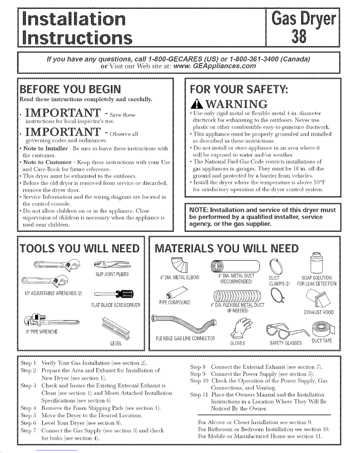
BEFORE YOU BEGIN
Read these instructions compLeteLy and c&re_[]yo
IM PO RTANT -Savethese
instructions for local inspector's use.
IMPORTANT -Ohservea.
governing codes and ordinances.
Note to Installer - Be sure to leave these instructions with
the customer.
Note to Customer Keep these instructions with your Use
and Care Book fbr flmlre refi_rence.
This dryer must be exhausted to the outdoors.
Before the old dryer is removed from service or discarded,
remove the dryer door.
Service Information and the wiring diagram are located in
the control console.
Do not allow children on or in the appliance. Close
supervision of chiklren is necessary when the appliance is
used near chiklren.
TOOLS YOU WILL NEED
10"ADJUSTABLEWRENCHES{2)
SLIPJOINTPLIERS
FLATBLADESCREWDRIVER
8"PIPEWRENDHE
%
LEVEL
FOR YOUR SAFETY:
A
, Use only rigid metal or flexible metal 4-in. diameter
ductwork for exhausting to the outdoors. Never use
plastic or other combustible easy-to-puncture ductwork.
* This appliance must be properly grounded and installed
as described in these instructions.
" Do not install or store appliance in an area where it
will be exposed to water and/or weather.
, The National Fuel Gas Code restricts installations of
gas appliances in garages. They must be 18 in. off the
ground and protected by a barrier from vehicles.
, Install the dryer where the temperature is above ,50°F
for satisfhctory operation of the dryer control system.
MATERIALS YOU WILL NEED
%
4"DIA.METALELBOW
PIPECOMPOUND
FLEXIBLEGASLINECONNECTOR
4"DIA,METALDUCT DUCT
(RECOMMENDED) CLAMPS{2)
4"DIA.FLEXIBLEMETALDUCT
(IFNEEDED)
GLOVES
SOAPSOLUTION
FORLEAKDETECTION
EXHAUSTHOOD
SAFETYGLASSES DUCTTAPE
Step 1
Step 2
Step 3
Step 4
Step 5
Step 6
Step 7
VerifY/Your Gas Installation (see section 2).
Prepare the Area and Exhaust for Installation of
New Dryer (see section 1).
Check and Insure the Existing External Exhaust is
Clean (see section 1) and Meets Attached Installation
Specifications.(see section 6)
Remove the Foam Shipping Pads (see section 1).
Move the Dryer to the Desired Location.
Level _)ur Dryer (see section 8).
Connect the Gas Supply (see section 3) and check
fbr leaks (see section 4).
Step 8 Connect the External Exhaust (see section 7).
Step 9 Connect the Power Supply (see section 5).
Step 10 Check the Operation of the Power Supply, Gas
Connections, and Venting.
Step 11 Place the Owners ManuN and the Installation
Instructions in a Location Where They Will Be
Noticed By the Owner.
For Alcove or Closet Installation see section !1.
For Bathroom or Bedroom Installation see section 10
For Mobile or Manufactured Home see section 11.
Page 2

lnsta mation Instructions
Minimum CUearance Other Than AUcove or CUoset Installation
Minimum clearance to combustible surfaces and for air opening are: 0 in. clearance both sides and 1hr. rear. Consideration
must be given to provide adequate clearance ]br proper operation and service.
[] PREPARING FOR INSTALLATION
OF NEW DRYER
CSA(AGA)APPROVED
NEWFLEXIBLEGAS
LINECONNECTOR
GAS
INLET
PIPE
EXTERNAL
DUCT
OPENING
DUCT
TAPE
4"METALDUCT
DUCT
TAPE
TIP: Install your dryer before installing your washer.
This will allow better access when installing dryer exhaust.
DISCONNECTING GAS
DISCONNECTANDDISCARDOLD
FLEXIBLEGASCONNECTOR
ANDOLDDUCTINGMATERIAL,
TURNGAS
SHUT-OFF
VALVETOTHE
OFFPOSITION,
WARNING- NEVER REUSE OLD
FLEXIBLE CONNECTORS.
The use of old flexible connectors can cause leaks and
personal injury. Ahvays use new flexible connectors when
installing gas appliances.
REMOVING LINT FROM WALL
EXHAUST OPENING
WALL
/
INTERNALDUCT CHECKTHATEXHAUST
OPENING OPENS
ANDCLOSESFREELY,
TILTTHEDRYERSIDEWAYS
ANDREMOVETHEFOAM
SHIPPINGPADSBY
PULLINGATTHESIDES
ANDBREAKINGTHEM
AWAYFROMTHEDRYER
LEGS,BESURETO
REMOVEALLOFTHE
FOAMPIECESAROUND
THELEGS,
[] GAS REQUIREMENTS
,_ WARNING
. Installation umst conlbrm to local codes and ordinances,
or in their absence, the NATIONAL FUEL GAS CODE,
ANSI Z223.
° This gas dryer is equipped with a Valve & Burner Assem-
bly fbr use only with natural gas. Using conversion kit
WE25X0217, your local service organization can convert
this dryer for use with propane (LP) gas. ALL CONVER-
SIONS MUST BE MADE BY PROPERLY TRAINED
AND QUALIFIED PERSONNEL AND IN AC-
CORDANCE WITH LOCAL CODES AND ORDI-
NANCE RE©_HREMENTS.
" The dryer nmst be disconnected fl*om the gas supply
piping system during any pressure testing of that system
at a test pressure in excess of 0,5 PSI (3A KPa).
" The dryer nmst be isolated from the gas supply piping
system by closing the equipment shut-offvalve during
any pressure testing of the gas supply piping of test
pressure equal to or less than 0.5 PSI (3.4KPa).
DRYER GAS SUPPLY CONNECTION
2_q518,, _ 318"NPTMALETHREADGASSUPPLY
NOTE:Addtoverticaldimension
thedistancebetweencabinet
bottomtofloor,
GAS SUPPLY
" A 1/8-in. National Pipe %per thread plugged rapping, ac-
cessible %r test gauge connection, nmst be installed imme-
diately upstream of the gas supply connection to the dryer.
Contact your local gas utility should you have questions on
the installation of the plugged tapping.
" Supply line is to be 1/2-in. rigid pipe and equipped with an
accessible shut-offwithin l; R. of; and in the same room
with, the dryer.
, Use pipe thread sealer compound appropriate for natural
or LP gas or use Teflon tape.
" Connect flexible metal connector to dryer and gas supply.
2
Page 3
lnsta!lation Instructions
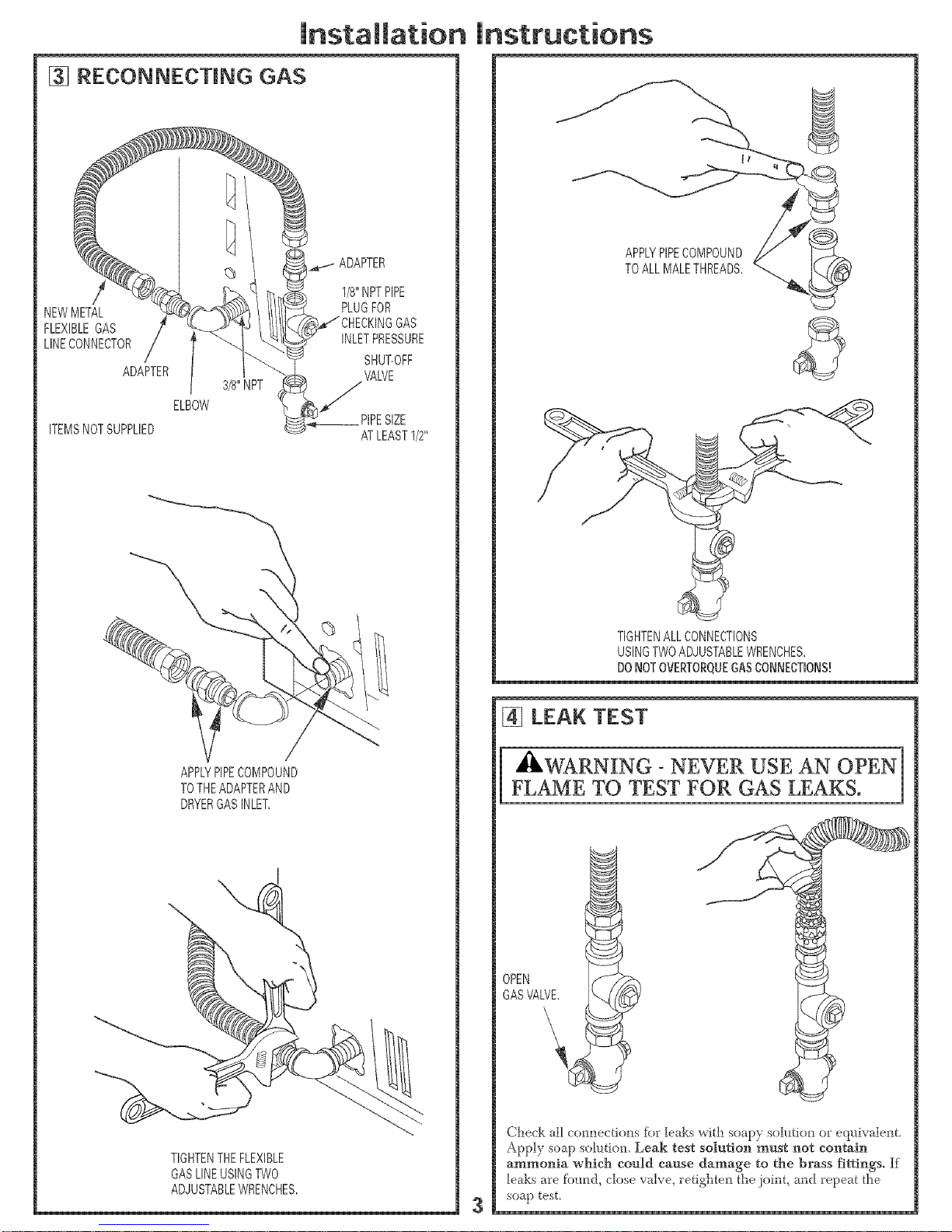
[] RECONNECTING GAS
NEWMETAL
FLEXIBLEGAS
LINECONNECTOR
ADAPTER
ITEMSNOTSUPPLIED
ELBOW
3/8"NPT
1/8"NPTPIPE
PLUGFOR
GAS
INLETPRESSURE
SHUT-OFF
VALVE
/
__ PIPESIZE
ATLEAST1/2"
APPLYPIPECOMPOUND
TOTHEADAPTERAND
DRYERGASINLET,
\
TIGHTENTHEFLEXIBLE
GASLINEUSINGTWO
ADJUSTABLEWRENCHES,
APPLYPIPECOMPOUND
TOALLMALETHREADS,
TIGHTENALLCONNECTIONS
USINGTWOADJUSTABLEWRENCHES,
DONOTOVERTORQUEGASCONNECTIONS!
[] LEAK TEST
[ _WARNING - NEVER USE AN OPEN
FLAME TO TEST FOR GAS LEAKS.
OPEN
GASVALVE,
Check all connecti(uls [br leaks with soapy solution or e<l_livalent.
Apply soap solution Leak test solution must not contain
ammonia which could cause damage to the brass fittings. If
leaks are fi_und, close valve, retigllten tile joint, mid repeat the
soap test.
Page 4

lnstaNmat[on
[] ELECTRICAL CONNECTION
A
WARNING- TO REDUCE THE RISK OF
FIRE, ELECTRICAL SHOCK, AND PERSONAL
INJURY:
DO NOT USE AN EXTENSION CORD OR AN
ADAPTER PLUG WITH THIS APPLIANCL
Dryer must be electrically grounded in accordance with
local codes and ordinances, or in the absence of local
codes, in accordance with the NATIONAL ELECTRI-
CAL CODE, ANSI/NFPA NO. 70.
ELECTRICAL REQUIREMENTS
This applim_ce must be supplied with 120V, 60Hz, and connected
to a properly grounded branch circuit, protected by a 1.5-or 20-
amp circuit breaker or time-delay fltse. If electrical supply provid-
ed does not meet the above specifications, it is recommended that
a licensed electriciml install ml approved outlet.
3 - THIS DRYER IS EQUIPPED
A THREE-PRONG (GROUNDING) PLUG FOR
YOUR PROTECTION AGAINST SHOCK
HAZARD AND SHOULD BE PLUGGED
DIRECTLY INTO A PROPERLY GROUNDED
THREE-PRONG RECEPTACLE. DO NOT CUT
OR REMOVE THE GROUNDING PRONG
FROM THIS PLUG.
ENSURE PROPER GROUND EXISTS BEFORE USE.
(-
IFLOCALCODESPERMIT,
ANEXTERNALGROUNDWIRE
(NOTPROVIDED),WHICHMEETS
LOCALCODES,MAYBEADDED
BYATTACHINGTOTHEGREEN
GROUNDSCREWONTHEREAR
OFTHEDRYER,ANDTOA GROUNDED
METALCOLDWATERPIPEOROTHER
ESTABLISHEDGRODND,
4
h structions
[] EXHAUST INFORMATION
A
IHLWARNING - USE ONLY METAL 4-IN. DUCT.
DO NOT USE DUCT LONGER THAN SPECIFIED
IN THE EXHAUST LENGTH TABLE.
Exhm_st longer thml specified will:
° Increase the drying times mid the energy cost.
° Reduce the dryer life.
° Accumulate lint, creattag a potential fire hazard.
The correct exhaust installation is your responsibility,
Problems due to incorrect installation are not covered
by the warranty.
The MAXIMUM ALLOWABLE length of the exhmlst system
depends _lpon the type of duct, number of turns, the type of
exhmlst hood (wall cap), and all conditions noted below. Both
rigid and flexible metal duct are shown in the table below.
EXHAUST LENGTH
RECOMMENDED MAXIMUM LENGTH
Exhaust Hood Types
Recommended
No. of 90° Rigid Flexible
Elbows Metal Metal
0 45 Feet 30 Feet
1 35 Feet 20 Feet
2 25 Feet 10 Feet
3 15 Feet
Use only for short
run installations
4" OIA,
;b
Rigid Flexible
Metal Metal
30 Feet 15 Feet
20 Feet 10 Feet
10 Feet
If ustag flexable metal duct, please refbr to page 6
EXHAUST SYSTEM CHECK LIST
HOOD OR WALL CAP
"_rminate in a rnanner to prevent back drafts or entry of birds or
other wildlii_.
•Termination should present minimal resistance to the exlmust air flow
and should require little or no maintenance to prevent clogging.
•Never install a screen in or over the exhaust duct.
°W_ll caps m!_stbe installed at least 12 in. above ground level or any other
obstruction with the opening pointed down.
°If roof vents or louvered pMmms are used, they must be eql_ivalent to a
44n. dampened wall cap in regard to resistance to air flow, prevention of
back drafts, and maintenance required to prevent cloggtag.
SEPARATION OF TURNS
For best perfbrmance, separate all turns by at least 4 ft. of straight d!_ct,
including distance between last turn and dampened wail cap.
TURNS OTHER THAN 90°
• One turn of45 ° or less may be ignored.
o
°_ivo 45 turns should be treated as one 90° turn.
( O
( • , _(/°Each turn _.ei k should be treated as one 90 turn.
SEALING OF JOINTS
•All joints stlould be tight to avoid leaks. The male end of each section of
duct must point away fi'om the dryer.
•Do not assemble the ductwork with fbsteners that extend into the duct.
They will serve as a collection point tbr lint.
•Duct joints sho_fldbe made air-and moismre4ight by wrapping the
overlapped joints with duct tape.
•Horizontal runs should slope down towards outdoors 1/2 inch pet' tbot.
INSULATION
•Duct work that runs through an unheated area or is neat' air conditioning
should be insulated to re&_ce condensation and lint bldld l_p.
Page 5

lnstamlation Instructions
[] EXHAUST CONNECTION
G - TO REDUCE THE RISK
OF FIRE OR PERSONAL INJURY:
" This dryer nmst be exhausted to tile outdoors.
" Use oniy metal duct.
/
" Do not terminate exhaust in a chimney, any gas vent,
under an enclosed floor (craw] space), or into an attic.
The accumuh_ted ]int cou]d create a fire hazard.
. Provide an access for inspection and cleaning of the
exhaust system, especiM]y at turns. Inspect and dean at
]east once a year.
° Never terminate the exhaust into a common duct with a
kdtchen exhaust. A combination of lint and grease could
create a fire hazard.
° Do not obstruct incoming or exhausted air.
WE RECOMMEND THAT YOU iNSTALL YOUR DRYER
BEFOREYOUR WASHER. THIS WILL PERMIT DIRECT
ACCESS FOR EASIEREXHAUST CONNECTION
THIS DRYERCOMES READY FORREAREXHAUSTING. IF
SPACEIS LIMITED, USE THE INSTRUCTIONS IN SECTION
12 TO EXHAUST DIRECTLYFROM THE LEFTSIDE OR
BOTTOM OF THE CABINET.
STANDARD REAR EXHAUST
WESTRONGLYRECOMMENDTHEUSEOF
RIGIDMETALEXHAUSTDUCT.IFUSING
FLEXABLEMETALDUCT,CUTITTOTHEPROPER
LENGTHANDAVOIDBUNCHINGOFTHEDUCT
BEHINDTHEDRYER,
5
FORSTRAIGHT
LINEINSTALLATION,
CONNECTTHE ELBOWHIGHLY
DRYEREXHAUST "_ RECOMMENDED,
TOTHEWALLUSING
DUCTTAPE,
ELBOWHIGHLY
RECOMMENDED,-
RECOMMENDED
CONFIGURATION
TOMINIMIZE
EXHAUST
BLOCKAGE,
NOTE: ELBOWS WiLL PREVENT DUCT
KiNKiNG AND COLLAPSING.
[] LEVEUNG DRYER
LEVEL
FRONT-TO-BACK,
,.,..,, LEVEL
SIDE-TO-SIDE,
4LEVELINGLEGS
STANDTHEDRYERUPRIGHTNEARTHE
FINALLOCATIONANDADJUSTTHE4LEVELING
LEGSTOMATCHTHEHEIGHTOFYOURWASHER,
ADJUSTTHE2ANTI-TIPLEGSTOCONTACT
THEFLOOR,
2ANTI-TIPLEGS
Page 6

Installation Instructions
USING FLEXNBLE METAL DUCTS
If rigid all-nletal duct cmmot be used, then flexible all-metal
venting cml be used, but it will reduce the maxinmm
rec(_mmended duct length In special installations when it is
impossible to make connection with the above recommendations,
then ULdisted clothes dryer trmlsition duct may be used as
transition venting between the dryer mid wall connection only. The
use of this ducting will affbct dry time.
If flexible transition duct is necessary, the fbllowing directions must
be f_llowed
• Use the Shortest Length Possible.
• Stretch the Duct to Its Maximum Length
• Do Not Crush or Collapse.
• Never Use Trmlsition Duct Inside the Wall or
Inside the Dryer.
• Avoid Resting the Duct on Sharp Objects.
• Venting Must Conf_rm to Local Building Codes.
ELBOWHIGHLY
RECOMMENDED
ELBOWSHIGHLY
DONOTUSE
EXCESSIVE
EXHAUST
LENG
)(
6
[] ALCOVE OR CLOSET NSTALLATION
" If your dryer is approved for installation in an alcove or
closet, it will be stated on a label on the dryer back.
. The dryer MUST be vented to the outdoors. See the
EXHAUST INFORMATION section.
"Minfinum clearance between dryer cabinet and adjacent
walls or other surfaces is:
0 in. either side
3 in. front and rear
° Minimum vertical space from floor to overhead cabinets,
ceiling, etc. is 52 in.
. Closet doors nmst be louvered or otherwise ventilated and
must contain a minimum of 60 sq. in. of open area equally
distributed. If the closet contains both a washer and a
dryer, doors nmst contain a nfininmm of 120 sq. in. of open
area equally distributed.
. The closet should be vented to the outdoors to prevent gas
pocketing in case of a gas leak in the supply line.
. No other flleLburning appliance shMl be installed in the
same closet with the dryer.
[] BATHROOM OR BEDROOM
IN STALLATION
" The dryer MUST be vented to the outdoors. See
EXHAUST INFORMATION section l;.
"The installation nmst confbrm with locM codes or, in the
absence of local codes, with the NATIONAL FUEL GAS
CODE, ANSI Z223.
[] MOBILE OR MANUFACTURED
HOME INSTALLATION
. Installation must conform to the MANUFACTURED
HOME CONSTRUCTION & SAFETY STANDARD,
TITLE 24, PART 32_80 or, when such standard is not
applicable, with AMERICAN NATIONAL SXANDARD
FOR MOBILE HOME, NO. 501B.
The dryer MUST be vented to the outdoors with the
termination securely fastened to the mobile home
structure. (See EXHAUST INFORMATION section 6.)
° The vent MUST NOT be terminated beneath a mobile or
nmnufhcmred home.
The vent duct material MUST BE METAL.
KIT 14-D3All-33 MUST be used to attach the dryer
securely to the structure.
The vent MUST NOT be connected to any other duct,
vent, or chimney.
" Do not use sheet metal screws or other refastening
devices which extend into the interior of the exhaust vent.
*Provide an opening with a fiee area of at least 25 sq in.
fbr introduction of outside air into the dryer room.
Page 7

Installation Instructions
[] DRYER EXHAUST TO LEFT OR
BOTTOM OF CABINET
_- PROTECT YOUR HANDS
AND ARMS FROM SHARP EDGES
WHEN WORKING INSIDE CABINEZ
REMOVE
SCREW
ANDSAVE,
O_ REMOVE/
DESIRED
KNOCKOUT
(ONEONLY),
Detach and remove the bottom or left side knockout as
desired. Remove the screw inside the dryer exhaust duct
and save. Pu]] the duct out of the dryer. Protect sharp edges
around the knockout and exhaust opening with rope.
FIXINGHOLE
\\
B A
[-_- 9"
Cut the duct as shown and keep portion A.
TAB LOCATION
BEND
TAB45°
Through the rear opening, locate the tab in the middle of
the appliance base. Lift the tab to about 45 ° using a fiat
blade screwdriver.
ADDING NEW DUCT
FIXING
HOLE
PORTION"A"
LEFTSIDE
EXHAUST
Reconnect the cut portion (A) of the duct to the blower
housing. Make sure that the fixing hole is aligned with the
tab in the base. Use the screw saved previously to secure the
duct in place through the tab on the appliance base.
ADDING ELBOW AND DUCT FOR
EXHAUST TO SIDE OF CABINET
" Pre-assemble 4" elbow with 4" duct. Wrap duct rope
around joint.
, Insert duct assembly, elbow first, through the side opening
and connect the elbow to the dryer interna_ duct.
CAUTION: Be sure not to pull or damage the
electrical wires inside the dryer
when inserting the duct.
[_ DUCT
TAPE
/
"Apply duct tape as shown on the joint between the dryer
internal duct and the elbow.
DUCT
CAUTION:
internal duct joints must be
secured with tape, otherwise
they may separate and cause
a safety hazard,
Page 8

Installation
ADDING ELBOW FOR EXHAUST
THROUGH BOTTOM OF CABINET
" Insert the elbow through the rear opening and connect it to
the dryer internal duct.
, Apply duct tape oil the joint between the dryer internal
duct and elbow, as shown oil page 2
ADDING COVER PLATE TO REAR
OF CABINET
PLATE
(KITWE1M454)
Connect standard metM elbows and ducts to complete the
exhaust system. Cover back opening with a plate (Kit
WE1M454) available from your local service provider.
Place dryer in final ]ocation.
i _WARNING oNEVER LEAVE THE
For Ojlestions on Installation, Call: 1-800-62ti-2003 (US) or
500AISTP(/38 Pub #)1 15171i
instructions
[] CHANGING DIRECTION OF
DOOR OPENING
REMOVE4
HINGESCREWS,
REMOVE4HOLEPLUGSAND
PLACETHEMINTHEHOLES
ONTHEOPPOSITESIDE,
ROTATEDOOR1800
ANDREINSTALL,
[] SERVICING
WARNING _LABEL ALL WIRES
PPdOR TO DISCONNECTION WHEN
SERVICING CONTROLS. WIPdNG
ERRORS CAN CAUSE IMPROPER AND
DANGEROUS OPERATION AFTER
SERVICING/INSTALLATION.
For replacement parts and other information, refer to
Owner's Manual for servicing phone numbers.
 Loading...