

GE DNCD450GGAWC, GRDN510GM0WS, GTDN500GM0WS, GTDN500GM2WS, GTDP200GM2WW Installation Guide
...Page 1
Installation
Instructions
Gas Drger
Questions on installation? Call: 1-800-GECARES (US)
or Visit ou r Web site at: www.GEAppliances.com (US)
BEFOREYOU BEGIN
Read these instructions completely and
carefully.
•IMPORTANT- Savethese instructions for
local inspector's use.
•IMPORTANT- Observe all governing codes
and ordinances.
• Noteto Installer - Besureto leavethese
instructionswith the customer.
• Note to Customer - Keep these instructions
with gour Use and Care Book for future
reference.
• Before the old drger is removed from service or
discarded, remove the drger door.
• Inspect the drger exhaust outlet and straighten
the outlet walls if theg are bent.
• Service information and the wiring diagram
are located in the control console.
• Do notallow children on or inthe appliance.
Close supervisionof children is necessarg when
the applianceis used near children.
• Install the drgerwhere the temperatureis
aboveSO°Ffor satisfactorg operationof the
drger controlsgstem.
WARNING RBKOFFIRE
Toreducethe riskof severeinjurg or death,followall installation instructions.
Clothesdrger installationmust beperformed bg a qualified installer.
Installthe clothesdrger accordingto theseinstructions and in accordancewith local
codes.Intheabsenceof localcodes,installationmust comptgwith NationalFuelGas
Code,ANSIZ225.1/NFPA54or the CanadianNatural Gasand PropaneInstallationCode,
CSAB149.1.
ColifomioSafeDrinkingWaterond ToxicEnforcementAct.
Thisact requiresthe governor of Californiato publisha list of substancesknownto the
stateto causecancer,birth defectsor other reproductiveharm and requiresbusinesses
to warn customersof potentialexposureto suchsubstances.Gasappliancescan
causeminorexposuretofour of thesesubstances,namelgbenzene,carbonmonoxide,
formaldehgdeand soot,causedprimaritg bg the incompletecombustion of naturalgas
or LPfuels.Properlgadjusteddrgerswiltminimizeincompletecombustion.Exposure
to these substancescanbe minimizedfurther bg properlgventing the drger to the
outdoors.
Thisdrger must beexhaustedto theoutdoors.
Useonlg4"rigid metal ducting for exhaustingthe clothesdrger to the outdoors.
DONOTinstallaclothesdrger with flexibleplastic ducting materials.Ifflexible metal
(semi-rigidorfoit-tgpe)duct isinstalled,it mustbe ULlistedand installed inaccordance
with theinstructionsfound in "ConnectingTheDrgerTo HouseVent"on page6of this
manual.Flexibleventing materialsare knownto collapse,beeasilgcrushed,and trap
lint.Theseconditionswilt obstructdrger airflowandincreasethe risk offire.
Donotinstallor storethis appliance in ang locationwhereit could be exposedto water
andorweather.
Drgersinstalledinresidentialgaragesmust beelevated 18"(46cm)abovethefloor.
Savetheseinstructions.(Installers:Besureto leavethese instructionswith the
customer).
in the state of Massachusetts,installation must beperformed bya qualifiedor
licensedcontractor, plumber, or gasfitter qualified or licensedby the state.
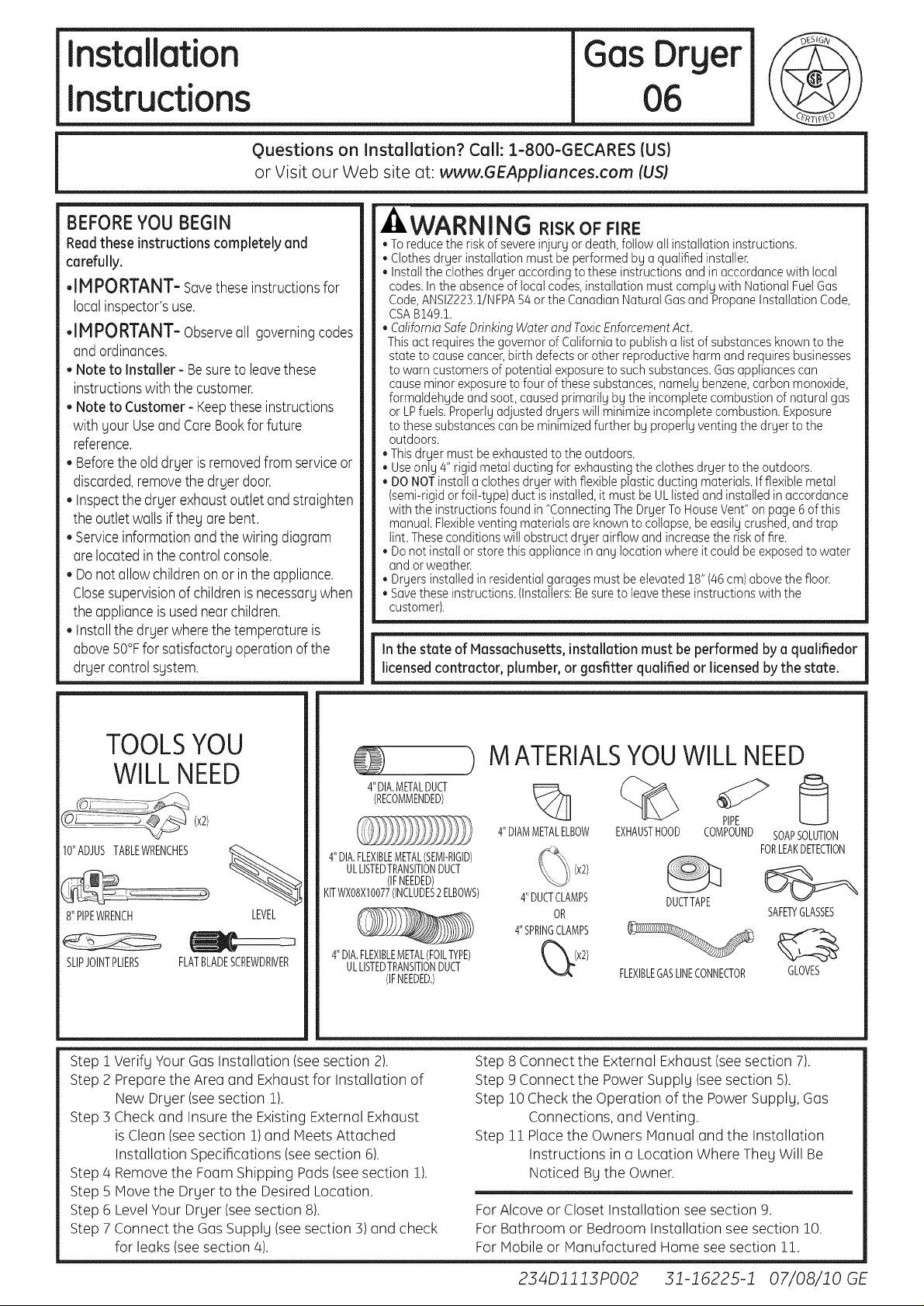
TOOLSYOU
WILLNEED
(x2)
IO"ADJUSTABLEWRENCHES _.
8"PIPEWRENCH LEVEL
SLIPJOINTPLIERS FLATBLADESCREWDRIVER
Verifg Your Gas Installation (seesection 2).
Step 1
Prepare the Area and Exhaust for Installation of
Step 2
New Drger (see section 1).
Check and Insure the Existing External Exhaust
Step 3
is Clean (seesection 1)and Meets Attached
Installation Specifications (see section 6).
Step 4 Remove the Foam Shipping Pads (seesection 1).
Step 5 Move the Drger to the Desired Location.
Step 6 Level Your Drger (seesection 8).
Step 7 Connect the Gas Supplg (seesection 3) and check
for leaks (see section 4).
4"DIA.METALDUCT I====_
(RECOMMENDED)
4"DIA.FLEXIBLEMETAL(SEMI-RIGID)
ULLISTEDTRANSITIONDUCT
(IFNEEDED)
KITWXO8X10077(INCLUDES2ELBOWS) 4"DUCTCLAMPS
4"DIA.FLEXIBLEMETAL(FOILTYPE) _(x2)
ULLISTEDTRANSITIONDUCT
(IFNEEDED.)
MATERIALSYOUWILLNEED
4"DIAMMETALELBOW
4"SPRINGCLAMPS
EXHAUSTHOOD COMPOUND
DUCTTAPE
FLEXIBLEGASLINECONNECTOR
Step 8 Connect the External Exhaust (see section 7).
Step 9 Connect the Power Supplg (seesection 5).
Step 10 Check the Operation of the Power Supplg, Gas
Connections, and Venting.
Step 11 Place the Owners Manual and the Installation
Instructions in a Location Where Theg Will Be
Noticed Bg the Owner.
For Alcove or Closet Installation see section 9.
For Bathroom or Bedroom Installation see section 10.
For Mobile or Manufactured Home see section 11.
PIPE
SOAPSOLUTION
FORLEAKDETECTION
SAFETYGLASSES
GLOVES
234Dll13PO02 31-16225-1 07/08/10 GE
Page 2
Installation instructions
Minimum Clearance Other Than Alcove or Closet Installation
Minimum clearance to combustible surfaces and for air opening are: 0 in. clearance both sides and 1in. rear.
Consideration must be given to provide adequate clearance for installation and service.
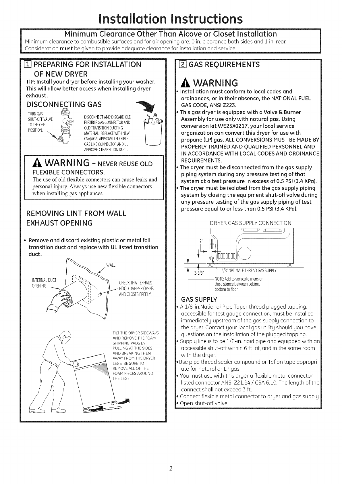
m PREPARING FOR INSTALLATION
OF NEW DRYER
TIP:Install your dryer before installing your washer.
This will allow better access when installing dryer
exhaust.
DISCONNECTING GAS
TURNGAS
SHUT-0FFVALVE IC?_ DISCONNECTANDDISCARDOLD f}_!/__
TOTHEOFF
POSITION.,,,_ OLDTRANSITIONDUCTING
j -,_ FLEXIBLEGASCONNECTORAND
MATERIAL.REPLACEWITHNEW
CSA(AGA)APPROVEDFLEXIBLE
GASLINECONNECTORANDUL
APPROVEDTRANSITIONDUCT.
WARNING - NEVERREUSEOLD
FLE×IBLE CON NECTORS.
The use of old flexible connectors can cause leaks and
personal iniury. Always use new flexible connectors
when installing gas appliances.
REMOVING LINT FROM WALL
EXHAUST OPENING
[] GAS REQUIREMENTS
WARNING
Installation must conform to local codes and
ordinances, or in their absence, the NATIONAL FUEL
GASCODE,ANSI Z223.
This gas dryer is equipped with a Valve & Burner
Assembly for use only with natural gas. Using
conversion kit WE25×0217, your local service
organization can convert this dryer for use with
propane {LP)gas. ALL CONVERSIONSlUST BEMADE BY
PROPERLYTRAINED AND QUALIFIEDPERSONNELAND
IN ACCORDANCEWITH LOCALCODESAND ORDINANCE
REQUIREMENTS.
The dryer must be disconnected from the gas supply
piping system during any pressure testing of that
system at a test pressure in excess of O.5 PSI{3.4 KPa).
The dryer must be isolated from the gas supply piping
system by closing the equipment shut-off valve during
any pressure testing of the gas supply piping of test
pressure equal to or less than 0.5 PSI(3.4 KPa).
DRYER GAS SUPPLY CONNECTION
xc:_ z:E_ j
, Remove and discard existing plastic or metal foil
transition duct and replace with ULlisted transition
duct.
WALL
INTERNALDUCT
OPENING OPENS
CHECKTHATEXHAUST
ANDCLOSESFREELY.
TILTTHE DRYERSIDEWAYS
AND REMOVE THE FOAM
SHIPPING PADS BY
PULLING AT THE SIDES
AND BREAKING THEM
AWAY FROM THE DRYER
LEGS, BE SURE TO
REMOVE ALL OF THE
FOAM PIECESAROUND
THE LEGS.
' 318"NPTHALETHREADGASSUPPLY
NOTE:Addtoverticoldimension
thedistancebetweencobinet
bottomtofloor.
GAS SUPPLY
A 1/8-in.National PipeTaper thread plugged tapping,
accessible for test gauge connection, must be installed
immediatelg upstream of the gas supplg connection to
the drger. Contact sour local gas utilitg should Sou have
questions on the installation of the plugged tapping.
Supplg line isto be 1/2-in. rigid pipe and equipped with an
accessible shut-off within 6 ft. of, and in the same room
with the drger.
Use pipe thread sealer compound orTeflon tape appropri-
ate for natural or LPgas.
You must use with this drger a flexible metal connector
listed connector ANSIZ21.24 / CSA6.10. The length of the
connect shall not exceed 3 ft.
Connect flexible metal connector to drger and gas supplg.
Open shut-off valve.
2
Page 3
Installation
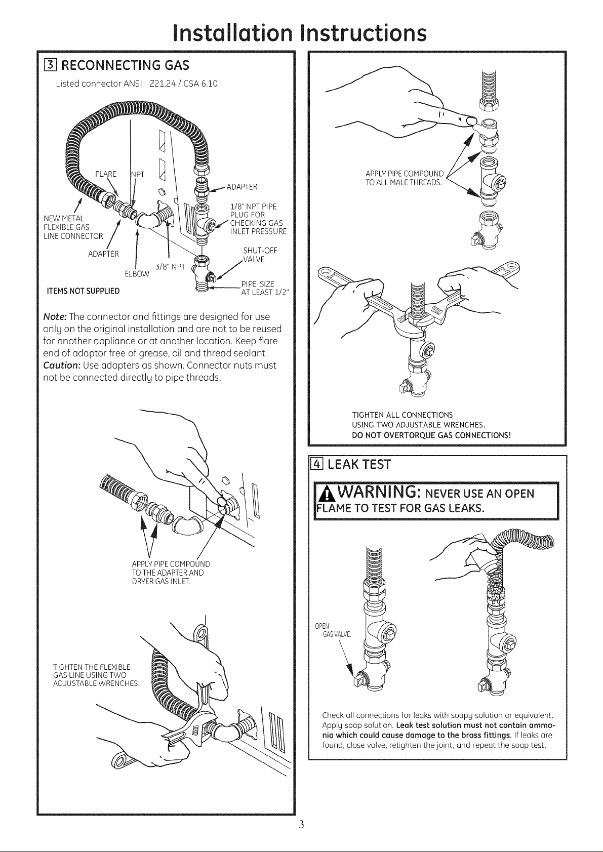
_] RECONNECTING GAS
Listed connector ANSI Z2!.24 / CSA 6.!0
1/8" NPTPIPE
NEW METAL PLUG FOR
FLEXIBLEGAS INLETPRESSURE
LINECONNECTOR
ADAPTER
3/8" NPT
ELBOW
ITEMSNOT SUPPLIED _AT LEAST1/2"
Note: The connector and fittings (]re designed for use
onlg on the original installation and (]re not to be reused
for another appliance or at another location. Keep flare
end of adaptor free of grease, oil and thread sealant.
Caution: Use adapters as shown. Connector nuts must
not be connected directlg to pipe threads.
GAS
SHUT-OFF
PIPE SIZE
Instructions
APPLYPIPECOMPOUND
TOALL HALETHREADS.
TIGHTEN THE FLEXIBLE
GAS LINE USING TWO
ADJUSTABLE WRENCHES.
APPLYPIPECOHPOUND
TOTHEADAPTERAND
DRYERGASINLET.
TIGHTEN ALL CONNECTIONS
USINGTWO ADJUSTABLE WRENCHES.
DO NOT OVERTORQUE GAS CONNECTIONS!
[-4]LEAK TEST
"WARNING: NEVERUSEAN OPEN
LAME TO TEST FOR GAS LEAKS.
OPEN
GASVALVE,
Check oil connections for teaks with soopg solution or equivalent.
Apptg soop solution. Leak test solution must not contain ammo-
nia which could cause damage to the brass fittings. If leaks ore
found, close volve, retighten the joint, and repeGt the soap test.
3
Page 4

Installation
Instructions
[-_ ELECTRICAL CONNECTION
INFORMATION
m
WARNING - TOREDUCETHE
RISK OF FIRE, ELECTRICAL SHOCK,
AND PERSONAL INJURY:
. DO NOTUSEAN EXTENSIONCORDORAN ADAPTER
PLUGWITH THIS APPLIANCE.
Dryer must be electrically grounded in accordance
with local codes and ordinances, or in the absence
of local codes, in accordance with the NATIONAL
ELECTRICALCODE,ANSI/NFPANO.70.
ELECTRICAL REQUIREMENTS
This appliance must be supplied with 120V,60Hz, and
connected to a properly grounded branch circuit,
protected by a 15- or 20- amp circuit breaker or time-
delay fuse. Ifelectrical supply provided does not meet the
above specifications, it is recommended that a licensed
electrician install an approved outlet.
,A,WARNING -THISDRYERIS
EQUIPPED A THREE-PRONG (GROUNDING)
PLUG FOR YOUR PROTECTION AGAINST
SHOCK HAZARD AND SHOULD BE PLUGGED
DIRECTLY INTO A PROPERLY GROUNDED
THREE-PRONG RECEPTACLE. DO NOT CUT
OR REMOVE THE GROUNDING PRONG FROM
THIS PLUG.
[-6-]EXHAUST INFORMATION
WARNING -IN CANADAANDINTHE
UNITED STATES,THE REQUIRED EXHAUST DUCT
DIAMETER IS 4 IN (102ram). DO NOT USEDUCT
LONGER THAN SPECIFIED INTHE EXHAUST
LENGTH TABLE.
Usingexhaustlongerthan specifiedlengthwill:
• Increasethedrying times andthe energycost.
• Reducethe dryer life.
• Accumulatelint,creatinga potential firehazard.
Thecorrect exhaustinstallation is YOURRESPONSIBILITY.
Problemsdueto incorrect installation are not coveredby
the warranty.
Removeanddiscordexisting plasticor metalfoil transition
duct and replacewith ULlistedtransition duct.
TheMAXIMUMALLOWABLEductlength and numberof
bendsof theexhaust systemdependsupon thetype ofduct,
numberof turns,the tgpe ofexhausthood(wallcap),and all
conditionsnoted below.Themaximumduct length for rigid
metal duct isshowninthetable below.
EXHAUST LENGTH
RECOMHENDEDHAXIHUH LENGTH
Exhaust Hood Tgpes
Recommended Use only for short
4" J_
No. of 90° Rigid
Elbows Metal
0 60 Feet
1 45 Feet
2 35 Feet
3 25 Feet
4 15 Feet
Rigid
Metal
90 Feet
60 Feet
45 Feet
35 Feet
25 Feet
run installations
4" DIA.
_l J..... 21/2"
ENSUREPROPERGROUND EXISTSBEFOREUSE.
IF LOCAL CODES PERHIT,
AN EXTERNAL GROUND WIRE
(NOT PROVIDED), WHICH HEETS
LOCAL CODES, HAY BE ADDED
BYATTACHING TO THE GREEN
GROUND SCREW ON THE REAR
OF THE DRYER,AND TO A GROUNDED
METAL COLD WATER PIPE OR OTHER
ESTABLISHED GROUND.
EXHAUST SYSTEM CHECK LIST
HOOD ORWALL CAP
• Terminateina manner to preventback draftsor entrgof birds
or otherwildlife.
• Terminationshouldpresentminimalresistanceto the exhaust
air flow and shouldrequirelittleor nomaintenanceto prevent
clogging.
•Neverinstalla screenin or overtheexhaust duct.Thiscould
causelint buildup.
• Wallcapsmust beinstalledat least12 in.abovegroundlevel
or any otherobstructionwith the openingpointeddown.
SEPARATIONOF TURNS
Forbest performance,separateallturns bgat least4 ft. of
straightduct, includingdistance betweenlastturn andexhaust
hood.
TURNSOTHERTHAN90°
• Oneturn of 45°or lessmeg beignored.
• Two450turnsshouldbetreated as one 900turn.
• Eachturn over450shouldbetreatedasone 900turn.
SEALINGOFJOINTS
• Alljointsshouldbetight to avoidleaks.Themaleendof each
sectionof duct must pointawagfromthe dryer.
• Donotassemblethe ductwork with fastenersthat extend into
the duct. Theywillserveasa collectionpointfor lint.
• Ductjoints can bemadeair and moisture-tightby wrapping
the overlappedjoints withduct tape.
• Horizontalrunsshouldslopedown toward theoutdoors l_inch
per foot
INSULATION
Ductwork that runs throughanunheatedareaor is near air
conditioningshouldbe insulatedto reducecondensationand
lintbuild-up.
4
Page 5

Installation instructions
[_ EXHAUST CONNECTION
WARNING - TOREDUCETHE
RISK OF FIRE OR PERSONAL INJURY:
* This clothes drger must be exhausted to the outdoors,
* Use onlg 4" rigid metal ducting for the home exhaust
duct.
* Use onlg 4" rigid metal or UL-listed flexible metal
(semi-rigid or foil-tgpe) duct to connect the drger
to the home exhaust duct. It must be installed
in accordance with the instructions found in
"Connecting The Drger To HouseVent" on page 6 of
this manual.
*Do not terminate exhaust in a chimneg, a wall,
a ceiling, gas vent, crawl space, attic, under an
enclosed floor, or in ang other concealed space of
a building. The accumulated lint could create a fire
hazard.
* Never terminate the exhaust into a common duct
with a kitchen exhaust sgstem. A combination of
grease and lint creates a potential fire hazard.
* Do not use duct longer than specified in the exhaust
length table. Longer ducts can accumulate lint,
creating a potential fire hazard.
*Never install a screen in or over the exhaust duct. This
will cause lint to accumulate, creating a potential fire
hazard.
* Do not assemble ductwork with ang fasteners
that extend into the duct. These fasteners can
accumulate lint, creating a potential fire hazard.
* Do not obstruct incoming or exhausted air.
* Provide an access for inspection end cleaning of
the exhaust sgstem, especiallg at turns and joints.
Exhaust sgstem shell beinspected end cleaned at
least once gear.
STANDARD REAR EXHAUST
(Vented obove floor level}
ELBOWHIGHLY
"-/'-_/¢RECOMMENDED
RECOMMENDED
CONFIGURATION
TOMINIMIZE
EXHAUST
BLOCKAGE,
ELBOWHIGHLY
RECOMMENDED-
NOTE: ELBOWS WILL PREVENT DUCT
KINKING AND COLLAPSING.
[] LEVELING DRYER
LEVEL
FRONT-TO-BACK,
"-.,.
LEVEL
SIDE-TO-SIDE.
THIS DRYER COMES READY FOR REAR
EXHAUSTING. IF SPACE IS LIMITED, USE
THE INSTRUCTIONS IN SECTION 9 TO
EXHAUST DIRECTLY FROM THE SIDES OR
BOTTOM OF THE CABINET.
STANDARD REAR EXHAUST
{Vented ot floor level}
FORSTRAIGHTLINEINSTALLATION,CONNECTTHEDRYEREXHAUSTTO
THEEXTERNALEXHAUSTHOODUSINGDUCTTAPEORCLAMR
CSA)AGA)APPROVED
NEWFLEXIBLEGAS
LINECONNECTOR
EXTERNAL
DUCT
OPENING
DUCTTAPEOR
DUCTCLAMP
NOTE:WE STRONGLYRECOMMENDSOLID METALEXHAUSTDUCTING.
HOWEVER,IFFLEXIBLEDUCTINGISUSEDITMUST BE UL-LISTEDMETAL
NOTPLASTIC.
GAS
INLET
PIPE
4IIMETALDUCT
(CUTTOPROPER
LENGTH) DUCTTAPEOR
DUCTCLAMP
4LEVELINGLEGS
STANDTHEDRYERUPRIGHTNEARTHE
FINALLOCATIONANDADJUSTTHE4 LEVELING
LEGSTOMATCHTHEHEIGHTOFYOURWASHER,
ADJUSTTHE2ANTI-TIPLEGSTOCONTACT
THEFLOOR,
5
2ANTI-TIPLEGS
Page 6

Installation
CONNECTING THE DRYER
TO HOUSE VENT
RIGIDMETALTRANSITIONDUCT
• Forbest drying performance,a rigid metaltransitionduct is
recommended.
• Rigidmetaltransitionsducts reducetheriskof crushingand
kinking.
UL-LISTEDFLEXIBLEMETAL(SEMI-RIGIDTRANSITIONDUCT
• tfrigid metulduct cannot be used,thenUL-listedflexiblemetul
(semi-rigid)ducting cun beused(KitWX08X10077).
Neverinstullflexible metulduct inwulls,ceilings,floors or
otherenclosedspaces.
Total lengthof flexiblemetal duct shouldnot exceed8 feet
(2.4m).
Formany applications,installingelbowsat boththedryer
undthe wull ishighly recommended(seeillustrutionsbelow).
Elbowsullowthe dryerto sitclosetothe wallwithout kinking
andor crushingthetransition duct,maximizingdrying
performance.
Avoidrestingthe duct on sharpobjects.UL-LISTEDFLEXIBLE
METAL(FOIL-TYPE}TRANSITIONDUCT
• tnspeciulinstullutions,it muy be necessurgto connectthe
dryerto the housevent usingu flexiblemetul(foiltype)duct.
A UL-listedflexiblemetul (foil-type)ductmuy be usedONLY
in instullutionswhererigid metulor flexiblemetul (semi-rigid)
ductingcunnot be usedANDwhereu4" diumeter cun be
muintuinedthroughout theentire lengthof thetrunsition
duct.
tnConuduundthe UnitedStutes,only theflexiblemetul(foil-
type) ductsthut comply with the "Outlinefor ClothesDryer
TrunsitionDuct Subject2158A"shullbe used.
Neverinstullflexible metulduct inwulls,ceilings,floors or
otherenclosedspuces.
Totul lengthof flexiblemetul duct shouldnot exceed8 feet
(2.4m).
Avoidrestingthe duct on shurpobjects.
Forbest drying performunce:
1.Slideoneendof theduct overthe clothesdryer
outlet pipe.
2.Securethe duct with u clump.
3.With the dryer initspermunent position,extendthe
duct to itsfull length.Allow2"of duct to overlupthe
exhuustpipe.Cut off und removeexcessduct. Keep
theduct usstruight us possiblefor muximumuirflow.
4.Securethe duct to theexhuust pipewith the other
clump.
ELBOWHIGHLY
REC0
"_<._ _ ELBOWSHIGHLY
d
Instructions
DONOTUSE
EXCESSIVE
EXHAUST
LENGTH
F9-1ALCOVE OR CLOSET INSTALLATION
• tfyourdryer isapprovedfor installationinan alcoveor closet,
it will bestatedon alabelon thedryer back.
• Thedryer MUSTbevented tothe outdoors.Seethe EXHAUST
INFORMATIONsection.
• Minimumcleuruncebetweendryercubinetundudjucent
wullsor other surfacesis:
0in.either side
3 in.front andrear
Minimumvertical spacefrom floorto overheadcabinets,
ceiling,etc.is 52 in.
Closetdoorsmustbe Iouveredorotherwise ventilatedand
mustcontain a minimumof 60sq.in. of openareaequally
distributed,ifthe closetcontainsboth a washeranda dryer,
doorsmust contain a minimumof 120sq.in,of openarea
equallydistributed.
Thecloset shouldbe ventedto the outdoorsto preventgas
pocketingincaseof a gasleukin the supplyline.
Noother fuel-burningappliance shallbeinstulledinthe some
closetwith the dryer.
I1OIBATHROOM OR BEDROOM INSTALLATION
• Thedryer MUSTbevented tothe outdoors.SeeEXHAUST
INFORMATIONsection 6.
• Theinstullationmustconformwith Ioculcodesor,inthe
ubsenceof Ioculcodes,with theNATIONALFUELGASCODE,
ANSIZ223.
[_]MOBILE OR MANUFACTUREDHOME INSTALLATION
• tnstullationmust conformto the MANUFACTUREDHOME
CONSTRUCTION& SAFETYSTANDARD,TITLE24,PART32-80
or,when suchstundard isnotapplicuble,with AMERICAN
NATIONALSTANDARDFORMOBILEHOME,NO.50lB.
• Thedryer MUSTbevented tothe outdoorswith the
terminution securelyfastenedto the mobilehomestructure.
(SeeEXHAUSTINFORMATIONsection6.)
• Thevent MUSTNOTbeterminutedbeneuthu mobileor
manufactured home.
• Thevent duct muteriul MUSTBEMETAL.
• KIT14-D346-33MUSTbe usedto uttuch thedryer securelyto
the structure.
• Thevent MUSTNOTbeconnectedto uny otherduct, vent,or
chimney.
• Donot usesheet metulscrewsor other refusteningdevices
which extendintothe interiorof theexhaustvent.
• Provideun openingwith u freeareuof ut leust25sq.in.or
introductionof outsideuir intothe dryer room.
6
Page 7

Installation
Instructions
[f2]DRYER EXHAUST TO RIGHT, LEFT
OR BOTTOM CABINET
THIS EXHAUST INSTALLATION, BE SURE
TO DISCONNECT THE DRYER FROM ITS
ELECTRICAL SUPPLY. PROTECT YOUR
HANDS AND ARMS FROM SHARP
EDGES WHEN WORKING INSIDE THE
CABINET. BE SURE TO WEAR GLOVES
/ .......
i
REMOVE
SCREW
ANDSAVE.
REMOVEjO
DESIRED
KNOCKOUT
(ONEONLY).
Detach and remove the bottom, right or left side knockout
us desired. Remove the screw inside the drger exhaust duct
and save. Pull the duct out of the dryer.
Note: Only 4" round rigid metal ducting allowed inside
dryer. FIXINGHOLE
ADDING NEW DUCT
FIXING
HOLE
PORTION"A"
LEFTSIDE
EXHAUST
Reconnectthe cut portion (A)of the duct to the blower
housing. Makesurethat the shortened duct isaligned with
the tab inthe base.Usethe screw saved previouslgto secure
the duct in place through the tab on the appliance base.
ADDING ELBOW AND DUCT FOR
EXHAUST TO LEFT SIDE OF CABINET
. Preassemble 4" elbow with 4" duct. Wrap duct tope
around joint.
. Insert duct assemblg, elbow first, through the side
opening and connect the elbow to the drger internal
duct.
CAUTION: Be sure not to pull or damage the
electrical wires inside the dryer when inserting the
duct.
B A
9"
Cut the duct as shown and keep portion A.
TAB LOC/_TION
BENDTAB
UP45o
Through the rear opening, locate the tab in the middle of
the appliance base. Lift the tab to about 45o using aflat
blade screwdriver.
DUCT
TAPE
, Applg duct tape as shown on the joint between the
drger internal duct and the elbow.
,TAPE CAUTION:
Internal ductjoints must be
secured with tape, otherwise
they may separate and cause
a safety hazard.
7
Page 8

Installation
Instructions
ADDING ELBOW FOR EXHAUST
THROUGH BOTTOM OF CABINET
, Insert the elbow through the rear opening and connect
itto the drger internal duct.
Applg duct tape on the joint between the drger internal
duct and elbow, us shown on page 7.
.J
CA
Internal duct joints must be secured with tape,
otherwise they may separate and cause a
safety hazard.
ADDING COVER PLATE TO REAR OF
CABINET
CHANGING DIRECTION OF
DOOR OPENING
REMOVE/4HOLEPLUGSAND
REMOVE4
HINGESCREWS.
PLACETHEIViINTHEHOLES
ONTHEOPPOSITESIDE.
PLATE
(KITWE1H858)
Connect standard metal elbows and ducts to complete
the exhaust sgstem. Cover back opening with a plate (Kit
WE11V1454)available from gout local service provider.
Placedrger in final location.
,_WARNING-NEVER LEAVE THE BACK
OPENING WITHOUT THE PLATE.
ROTATEDOOR1800
ANDREINSTALL.
8
Page 9

Installation
Instructions
[_] CONNECTING INLET HOSES
(onsome models)
To produce steam, the drger must connect to the cold
water supplg. Sincethe washer must also connect to the
cold water, a "`7"connector is inserted to allow both inlet
hoses to make that connection at the some time.
NOTE:Use the new inlet hoses provided; never
use old hoses.
1.Turn the cold water faucet off. Removethe washer inlet
hose from the washer fill valve connector (cold).
2. Ensure the rubber fiat washer isin place and screw
the female coupling of the short hose onto the washer fill
valve connector. Tighten bg hand until firmlg seated.
3. Attach the female end of the ",7"connector to the male
coupling of the short hose. Ensurethe rubber fiat washer
is in place. Tighten bg hand until firmlg seated.
4. Insert the filter screen inthe coupling of the washer's
inlet hose. If a rubber fiat washer
isalreadg in place remove it before installing
the filter screen. Attach this coupling to one male end of
the "`7"connector. Tighten bg hand until firmlg seated.
5. Ensure the rubber fiat washer isin place and attach
the drger's long inlet hose to the other male end of the
"`7"connector. Tighten bg hand until firmlg seated.
6. Ensure the rubber fiat washer isin place and attach
the other end of the drger's long inlet hose to the fill valve
connector at the bottom of the drger back panel. Tighten
bg hand until firmlg seated.
[_ CONNECTING INLET HOSES {cont.}
8. Turn the water faucet on.
9. Check for leaks around the '"7"connector,
faucet and hose couplings.
WATER SUPPLY REQUIREMENTS
Hot and cold water faucets MUSTbe installed within z_2
in. (107 cm) of gour washer's water inlet. The faucets
MUSTbe 3//4 in. (1.9cm)garden hose-tgpe so inlet hoses
can be connected. Water pressure MUSTbe between 10
and 120 pounds per square inch. ,Tourwater department
can advise gou of gour water pressure.
NOTE:A water softener is recommended to reduce
buildup of scale inside the steam generator if the home
water supplg is verg hard.
[_]SERVICING
WARNING- LABEL ALL WIRES
PRIOR TO DISCONNECTION WHEN
SERVICING CONTROLS. WIRING ERRORS
CAN CAUSE IMPROPER AND DANGEROUS
OPERATION AFTER SERVICING/
INSTALLATION.
For replacement parts and other information, refer to
Owner's Manual for servicing phone numbers.
7. Using pliers, tighten all the couplings with
an additional two-thirds turn.
NOTE:Do not overtighten. Damage to the couplings mag
result.
For Questions on Installation, Call: 1-800-626-2000 (US)or
1-800-561-33/4/4(Canada).
9
 Loading...