

GE DNCD450EG9WC, GHDX100EM0WW, GRDN510EM0WS, GRDN510EM2WS, GRDN510GM2WS Installation Guide
...Page 1
Installation
ElectricDryer
Instructions
Questions on installation? calk 1-800-GECARES (US)
or Visit our Web site at: www.GEAppliunces.com (US)
BEFORE YOU BEGIN
Readtheseinstructionscompletelyandcarefully.
•IMPORTANT- Save these instructionsfor
localinspector'suse.
•IMPORTANT- Observeall governingcodes
andordinances.
• Note to Installer - Besureto leavethese
instructionswith the customer.
• Note to Customer - Keeptheseinstructions
with your Useand CoreBookforfuture
reference.
• Beforethe old dryeris removedfrom serviceor
discorded,removethe dryerdoor.
• Inspectthe dryerexhaustoutlet andstraighten
the outlet wallsif they arebent.
• Serviceinformation andthe wiringalia-gram
arelocated inthe controlconsole.
• Do notallowchildrenon or inthe appliance.
Closesupervisionofchildren isnecessary
whenthe applianceis usednearchildren.
• Installthe dryerwherethe temperature is
above50°Ffor satisfactory operationof the
dryercontrol system.
O5
WARNING ruSKOFFree
, Toreduce the risk of severe injury or death, follow all installation
instructions.
, Clothes dryer installation must be performed by a qualified installer.
, Install the clothes dryer according to these instructions and in
accordance with local codes.
, Thisdryer must be exhausted to the outdoors.
, Useonly 4" rigid metal ducting for exhausting the clothes dryer to the
outdoors.
, DO NOTinstall a clothes dryer with flexible plastic ducting materials.
If flexible metal (semi-rigid orfoil-type) duct is installed, it must be
ULlisted and installed in accordance with the instructions found in
"Connecting The Dryer To House Vent" on page 5 of this manual.
Flexible venting materials are known to collapse, be easily crushed,
and trap lint. These conditions will obstruct dryer airflow and increase
the risk of fire.
, Do not install or store this appliance in any location where it could be
exposed to water and or weather.
, Save these instructions. (Installers: Besure to leave these instructions
with the customer).
NOTE: Installation and service of this dryer requires basic
mechanical and electrical skills. It is your responsibility to
contact a qualified installer to make the electrical connections.
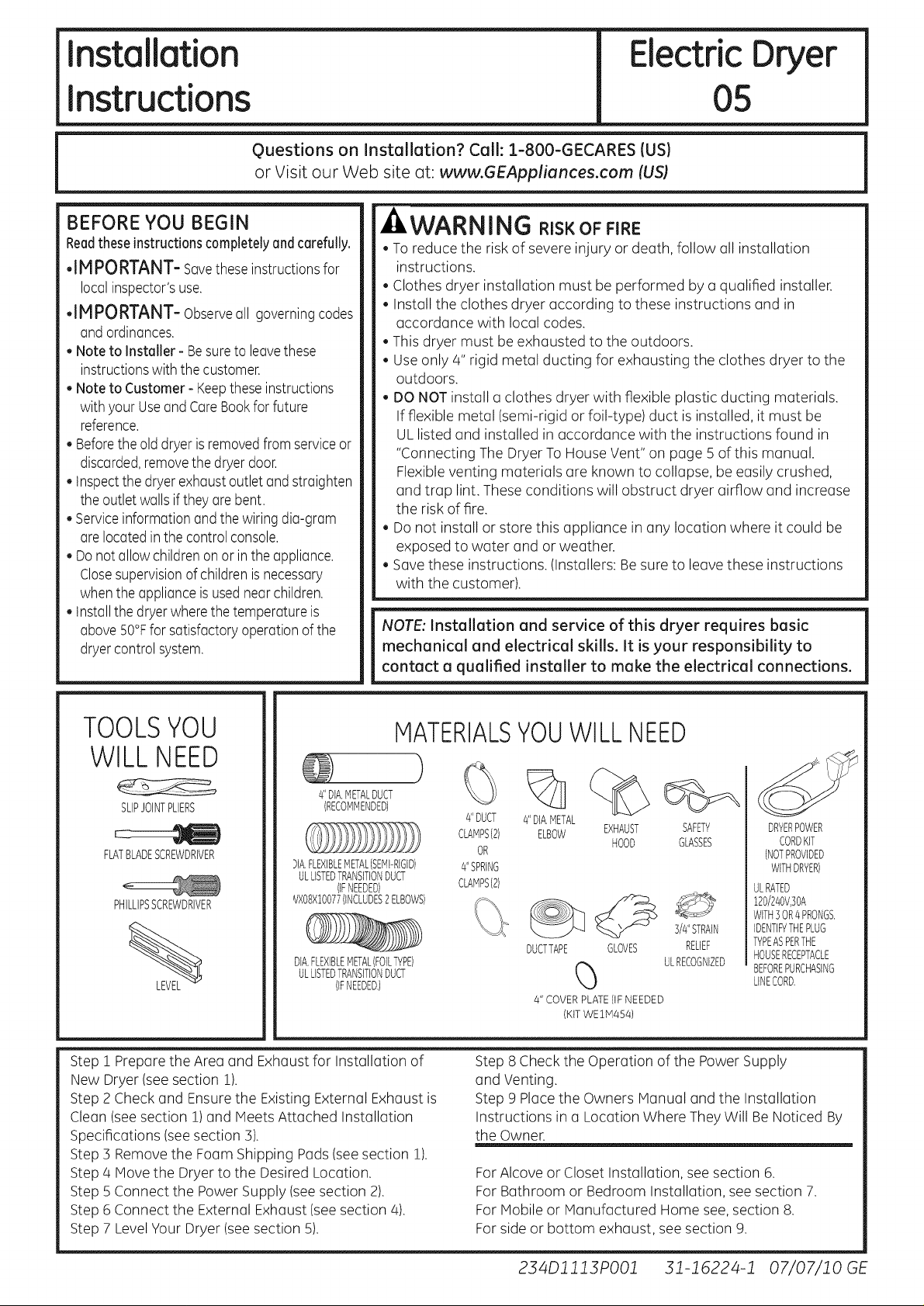
TOOLSYOU
MATERIALSYOUWILL NEED
WILLNEED
)
4IIDIA,METALDUCT
SLIPJOINTPLIERS
FLATBLADESCREWDRIVER
PHILLIPSSCREWDRIVER
Step 1 Prepare the Area and Exhaust for Installation of
New Dryer (seesection 1).
Step 2 Check and Ensurethe Existing External Exhaust is
Clean (seesection 1) and Meets Attached Installation
Specifications (seesection 3).
Step 3 Remove the Foam Shipping Pads(seesection 1).
Step 4 Move the Dryer to the Desired Location.
Step 5 Connect the Power Supply (see section 2).
Step 6 Connect the External Exhaust (see section 4).
Step 7 LevelYour Dryer (see section 5).
(RECOMMENDED)
}IA.FLEXIBLEMETAL(SEMI-RIGID)
ULLISTEDTRANSITIONDUCT
(IFNEEDED)
_,/XO8XlO077(INCLUDES2ELBOWS)
DIA.FLEXIBLEMETAL(FOETYPE)
ULLISTEDTRANSITIONDUCT
(IFNEEDED,)
%
4'IDUCT
CLAMPS(2) EXHAUST
4"SPRING
CLAMPS(2)
Step 8 Check the Operation of the Power Supply
and Venting.
Step 9 Place the Owners Manual and the Installation
Instructions in a Location Where They Will Be Noticed By
the Owner.
For Alcove or Closet Installation, see section 6.
For Bathroom or Bedroom Installation, see section 7.
For Mobile or Manufactured Home see, section 8.
For side or bottom exhaust, see section 9.
OR
4'1DIA,METAL
ELBOW
DUCTTAPE GLOVES RELIEF
4" COVERPLATE(IFNEEDED
(KITWEIM454)
HOOD
%
SAFETY
GLASSES
3/4"STRAIN
ULRECOGNIZED
DRYERPOWER
CORDKIT
(NOTPROVIDED
WITHDRYER)
ULRATED
120/240V,]OA
WITH3OR4PRONGS.
IDENTIFYTHEPLUG
TYPEASPERTHE
HOUSERECEPTACLE
BEFOREPURCHASING
LINECORD,
234Dll13PO01 31-16224-1 07/07/10 GE
Page 2
Installation instructions
Minimum Clearance Other Than Alcove or Closet Installation
Minimum clearance to combustible surfaces and for air opening are: 0 in. clearance both sides and 1in. rear.
Consideration must be given to provide adequate clearance for installation and service.
ri] PREPARING FOR INSTALLATION
OF NEW DRYER
TIP:Install your dryer before installing your washer.
This will allow better access when installing dryer
exhaust.
REMOVING LINT FROM WALL
EXHAUST OPENING
. Remove and discard existing plastic or metal foil
transition duct and replace with UL listed transition
duct.
WALL
/
INTERNALDUCT
OPENING i HOODDAMPEROPENS
CHECKTHATEXHAUST
ANDCLOSESFREELY.
TILTTHE DRYERSIDEWAYS
AND REMOVETHE FOAM
SHIPPING PADS BY
PULLING ATTHE SIDES
AND BREAKING THEM
AWAY FROM THE DRYER
LEGS, BE SURE TO
REMOVEALL OF THE
FOAM PIECESAROUND
THE LEGS,
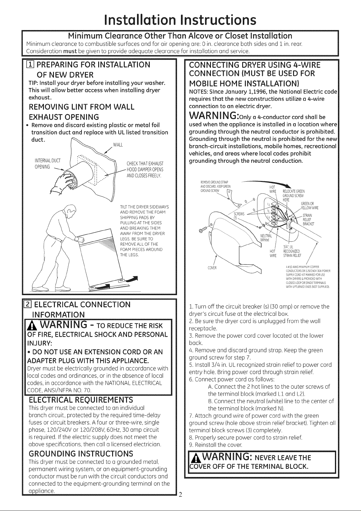
CONNECTING DRYER USING 4-WIRE
CONNECTION (MUST BE USED FOR
MOBILE HONE INSTALLATION)
NOTES:Since January 1,1996, the National Electric code
requires that the new constructions utilize a 4-wire
connection to an electric dryer.
WARNING:onlya4-conductorcordshallbe
used when the appliance is installed in a location where
grounding through the neutral conductor is prohibited.
Grounding through the neutral is prohibited for the new
branch-circuit installations, mobile homes, recreational
vehicles, and areas where local codes prohibit
grounding through the neutral conduction.
REivIOVEGROUNDSTRAP
ANDDISCARDKEEPGREEN
GROU"@SCREW ('_-/ WIRE RELOCATEGREEN
-_::::::_:3 _ HERE GREENOR
COVER
GROUNDSCREW
HOT
RECOGNIZED
STRAINRELIEF
WIRE
s/4",UL
N#10 AWG HR'_iHUIVICOPPER
CONDUCTORSOR120/240V 30APOWER
SUPPLYCORDKITHARKEDFORUSE
WITHDRYERS& PROVIDEDWITH
CLOSEDLOOPORSPADETERHINALS
WITHUPTURNEDENDS(NOTSUPPLIED)
RELIEF
BRACKET
[_] ELECTRICAL CONNECTION
INFORMATION
WARNING - ToREDUCETHERISK
OF FIRE, ELECTRICAL SHOCK AND PERSONAL
INJURY:
, DO NOT USE AN EXTENSION CORD OR AN
ADAPTER PLUG WiTH THiS APPLIANCE.
Dryer must be electrically grounded inaccordance with
local codes and ordinances, or in the absence of local
codes, in accordance with the NATIONALELECTRICAL
CODE,ANSI/NFPANO.70.
ELECTRICAL REQUIREMENTS
This dryer must be connected to an individual
branch circuit, protected by the required time-delay
fuses or circuit breakers. A four or three-wire, single
phase, 120/240V or 120/208V, 60Hz, 30 amp circuit
is required. If the electric supply does not meet the
above specifications, then call a licensed electrician.
GROUNDING INSTRUCTIONS
This dryer must be connected to a grounded metal,
permanent wiring system, or an equipment-grounding
conductor must be run with the circuit conductors and
connected to the equipment-grounding terminal on the
appliance.
1.Turn off the circuit breaker (s)(30amp) or remove the
dryer's circuit fuse at the electrical box.
2. Besure the dryer cord is unplugged from the wall
receptacle.
3. Removethe power cord cover located at the lower
back.
4. Remove and discard ground strap. Keepthe green
ground screw for step 7.
5. Install 3/4 in. UL recognized strain relief to power cord
entry hole. Bring power cord through strain relief.
6.Connect power cord as follows:
A. Connect the 2 hot lines to the outer screws of
the terminal block (marked L1 and L2).
B.Connect the neutral (white) line to the center of
the terminal block (marked N).
7.Attach ground wire of power cord with the green
ground screw (hole above strain relief bracket). Tighten all
terminal block screws (3)completely.
8. Properly secure power cord to strain relief.
9. Reinstall the cover.
,
2
Page 3
Installation instructions
CONNECTING DRYER USING 3-WIRE
CONNECTION
IFREQUIRED,BYLOCALCODE,
iNSTALLEXTERNALGROUND
(NOTPROVIDED)TOGROUNDED
METAL,COLDWATERPIPE,OR GREEN GROUND
OTHERESTABLISHEDGROUND GROUND STRAP
DETERMINEDBYAQUALiFiED SCREW
ELECTRiCiAN. HOT
COVER
WiRE STRAINRELIEF
NEUTRAL
(White) HOT
] #10AWGMINIMUMCOPPER
CONDUCTORSOR120/240V30APOWER
SUPPLYCORDKiTMARKEDFORUSE
WiTHDRYERS&PROVIDEDWiTHCLOSED
LOOPORSPADETERMINALSWiTH
UPTURNEDENDS(NOTSUPPLIED}.
BRACKET
WIRE
3/#',UL
RECOGNIZED
EXHAUST INFORMATION
WARNING -IN CANADAANDIN
THE UNITED STATES, THE REQUIRED EX-
HAUST DUCT DIAMETER IS 4. IN (102mm). DO
NOT USE DUCT LONGER THAN SPECIFIED IN
THE EXHAUST LENGTH TABLE.
Using exhaust longer than specified length will:
, Increase the drying times and the energy cost.
, Reducethe dryer life.
, Accumulate lint, creating a potential fire hazard.
The correct exhaust installation is YOUR
RESPONSIBILITY.Problems due to incorrect
installation are not covered by the warranty.
Remove and discard existing plastic or metal foil
transition duct and replace with ULlisted transition
duct.
The MAXIMUM ALLOWABLE duct length and number of
bends of the exhaust system depends upon the type of
duct, number of turns, the type of exhaust hood (wall
cap), and all conditions noted below. The maximum
duct length for rigid metal duct is shown in the table
below.
1.Turn off the circuit breaker(s)(30amp) or remove the
dryer's
circuit fuse at the electrical box.
2. Besure the dryer cord isunplugged from the wall.
3. Removethe power cord cover located at the lower
back.
4. Install 3/4 in. ULrecognized strain relief to power cord
entry hole. Bring power cord through strain relief.
5.Connect power cord as follows:
A. Connect the 2hot lines to the outer screws of
the terminal block (marked L1 and L2).
B.Connect the neutral (white) line to the center
of the terminal block (marked N).
6. Besure ground strap isconnected to neutral (center)
terminal of block and to green ground screw on cabinet
rear.Tighten all terminal block screws (3)completely.
7. Properly secure power cord to strain relief.
8. Reinstall the cover.
j|WARNING'. NEVER LEAVE THE j
COVER OFF OF THE TERMINAL BLOCK.
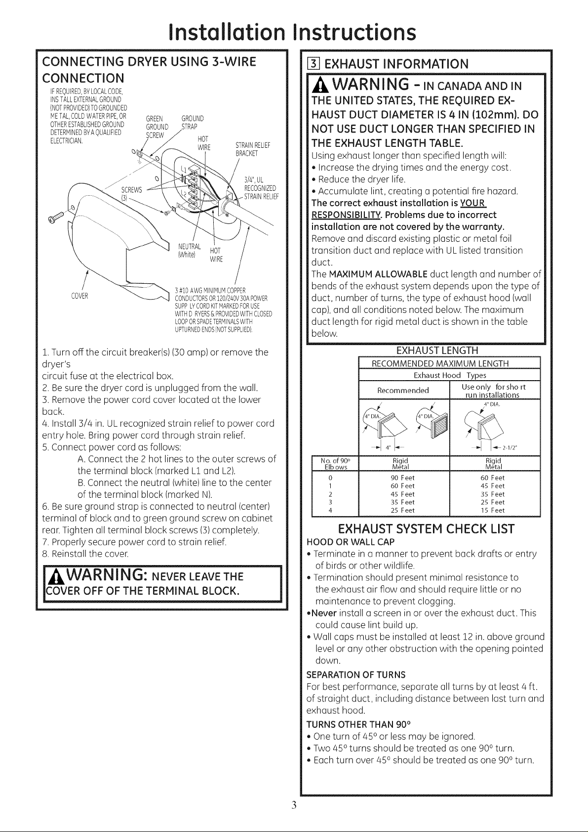
EXHAUST LENGTH
RECOMMENDED MAXIMUM LENGTH
Exhaust Hood Types
Recommended
4" I-_ I-4_ 2 1/2"
No.of 90 ° Rigid Rigid
EIbows Metal Metal
0 90 Feet 60 Feet
1 60 Feet 45 Feet
2 45 Feet 35 Feet
3 35 Feet 25 Feet
4 25 Feet 15 Feet
Useonly for sho rt
run installations
4" DIA.
EXHAUST SYSTEM CHECK LIST
HOOD ORWALL CAP
, Terminate in a manner to prevent back drafts or entry
of birds or other wildlife.
, Termination should present minimal resistance to
the exhaust air flow and should require little or no
maintenance to prevent clogging.
,Never install a screen inor over the exhaust duct. This
could cause lint build up.
, Wall caps must be installed at least 12 in. above ground
level or any other obstruction with the opening pointed
down.
SEPARATIONOF TURNS
Forbest performance, separate all turns by at least 4 ft.
of straight duct, including distance between last turn and
exhaust hood.
TURNSOTHERTHAN 90°
, Oneturn of 45oor less may be ignored.
, Two 45oturns should be treated as one 90oturn.
, Eachturn over 45o should be treated as one 90oturn.
3
Page 4

Installation
Instructions
EXHAUST INFORMATION (cont)
SEALING OFJOINTS
, AIIjoints should be tight to avoid leaks. The male end of
each section of duct must point away from the dryer.
, Do not assemble the ductwork with fasteners that
extend into the duct. Theywill serve as a collection
point for lint.
, Duct joints can be made air and moisture-tight by
wrapping the overlapped joints with duct tape.
, Horizontal runs should slope down toward the outdoors
1/2inch per foot
INSULATION
Duct work that runs through an unheated area or is
near air conditioning should be insulated to reduce
condensation and lint build-up.
[_ EXHAUST CONNECTION
_ZI,WARNING - TOREDUCE
THE
RISK OF FIRE OR PERSONAL INJURY:
, Thisclothes dryer must be exhausted to the outdoors.
, Useonly 4" rigid metal ducting for the home exhaust
duct.
, Useonly 4" rigid metal or UL-listed flexible metal
(semi-rigid or foil-type) duct to connect the dryer
to the home exhaust duct. It must be installed
in accordance with the instructions found in
"Connecting The Dryer To House Vent" on page 5 of
this manual.
, Donot terminate exhaust in a chimney, a wall,
a ceiling, gas vent, crawl space, attic, under an
enclosed floor, or in any other concealed space of
a building. The accumulated lint could create a fire
hazard.
, Neverterminate the exhaust into a common duct
with a kitchen exhaust system. A combination of =
grease and lint creates a potential fire hazard.
, Donot use duct longer than specified in the exhaust
length table. Longer ducts can accumulate lint,
creating a potential fire hazard.
, Never install a screen inor over the exhaust duct. This
will cause lint to accumulate, creating a potential fire
hazard.
, Donot assemble ductwork with any fasteners
that extend into the duct. These fasteners can
accumulate lint, creating a potential fire hazard.
, Donot obstruct incoming or exhausted air.
, Provide an access for inspection and cleaning of
the exhaust system, especially at turns and joints.
Exhaust system shall be inspected and cleaned at
least once a year.
THIS DRYER COMES READY FOR REAR
EXHAUSTING. IF SPACE IS LIMITED, USE
THE INSTRUCTIONS IN SECTION 9 TO
EXHAUST DIRECTLY FROM THE SIDES OR
BOTTOM OF THE CABINET.
STANDARD REAR EXHAUST
(Vented at all floor level}
FOR STRAIGHT LINE INSTALLATION,
CONNECT THE DRYER EXHAUST TO
THE EXTERNAL EXHAUST HOOD
USING DUCT TAPE OR CLAMP.
EXTERNAL
DUCT
OPENING
DUCT TAPE OR
DUCT CLAMP
4" METAL DUCT
(CUT TO PROPER
LENGTH) DUCT TAPE OR
NOTE: WE STRONGLY RECOMMEND SOLID METAL EXHAUST DUCTING.
HOWEVER, IF FLEXIBLE DUCTING IS USED IT MUST BE UL-LISTED METAL
NOT PLASTIC.
ELBOWHIGHLY
RECOMMENDED-
DUCT CLAMP
STANDARD REAR EXHAUST
(Vented above floor level)
ELBOWHIGHLY
_ RECOMMENDED
RECOMMENDED
CONFIGURATION
TOMINIMIZE
EXHAUST
BLOCKAGE.
NOTE:ELBOWSWILL PREVENTDUCT
KINKINGAND COLLAPSING.
[_ LEVELING AND STABILIZING YOUR DRYER
STAND THE DRYER UPRIGHT NEAR THE FINAL LOCATION AND ADJUST
THE 4 LEVELING LEGS, AT THE CORNERS, TO ENSURE THAT THE DRYER
IS LEVEL FROM SIDE TO SIDE AND FRONT TO REAR.
LEVEL
FRONT TO-BACK
LEVEL
SOETO-SDE
RLEVELNGLEGS
2ANTTPLEGS
4
Page 5

Installation instructions
CONNECTING THE DRYERTO HOUSEVENT
RIGIDMETALTRANSITIONDUCT
• Forbest dryingperformance,a rigid metaltransition duct is
recommended.
• Rigidmetaltransitionsducts reducethe riskof crushingand
kinking.
UL-LISTEDFLEXIBLEMETAL(SEMI-RIGID}TRANSITIONDUCT
• tf rigid metalduct cannot beused,thenUL-listedflexiblemetal
(semi-rigid)ducting can beused(KitWX08XZ0077).
• Neverinstallflexible metalduct inwalls,ceilings,floorsor
otherenclosedspaces.
Total lengthofflexiblemetal duct shouldnot exceed8 feet
(2.4m).
Formany applications,installingelbowsat both the dryer
andthe wallishighlyrecommended(seeillustrationsbelow).
Elbowsallow the dryerto sitcloseto the wallwithout kinking
andor crushingthetransition duct, maximizingdrying
performance.
•Avoidrestingtheduct on sharpobjects.
UL-LISTEDFLEXIBLEMETAL(FOIL-TYPE}TRANSITIONDUCT
• tn specialinstallations,itmaybenecessaryto connectthe
dryerto the houseventusinga flexiblemetal(foil-type)duct.
A UL-listedflexiblemetal (foil-type)ductmay beusedONLY
in installationswhererigid metalor flexiblemetal(semi-rigid)
ductingcannot beusedANDwherea4" diameter can be
maintainedthroughout theentire lengthof the transition
duct.
• tn Canadaandthe UnitedStates,onlythe flexiblemetal(foil-
type)ductsthat complywith the"Outlinefor ClothesDryer
TransitionDuct Subject2158A"shallbe used.
• Neverinstallflexible metalduct inwalls,ceilings,floorsor
otherenclosedspaces.
Total lengthofflexiblemetal duct shouldnot exceed8 feet
(2.4m).
•Avoidrestingtheduct on sharpobjects.
Forbest dryingperformance:
1.Slideoneend ofthe ductoverthe clothesdryeroutlet pipe.
2.Securetheduct with a clamp.
3.With thedryer initspermanentposition,extendthe duct
to its full length.Allow2"ofductto overlapthe exhaust pipe.
Cutoff and removeexcessduct. Keepthe duct asstraight as
possiblefor maximum airflow.
/4.Securetheduct to the exhaustpipewith theother clamp.
rssmq
EXCESSLVE
EXHAUST _}LENG_ .................................................EXHAUSTAGALNSTFLEXLBLEDOCRUSHNOT
ALCOVE OR CLOSET INSTALLATION
• tfyour dryerisapprovedfor installationinan alcoveor closet,
itwill bestatedon a labelon the dryerback.
•ThedryerMUSTbeventedto the outdoors.Seethe EXHAUST
INFORMATIONsections3 &/4.
• Minimumclearancebetweendryercabinetand adjacentwalls
or other surfacesis:
0 in.eitherside
3 in.front and rear
Minimumvertical spacefromfloorto overheadcabinets,
ceiling,etc.is 52in.
Closetdoorsmustbe Iouveredor otherwiseventilated and
mustcontaina minimum of60 sq.in.of openareaequally
distributed,tf theclosetcontainsbotha washerand a dryer,
doorsmust containaminimum of 120sq.in. ofopen area
equallydistributed.
[-7]BATHROOM OR BEDROOM INSTALLATION
• The dryer MUST be vented to the outdoors. See
EXHAUSTINFORMATIONsection 3 & 4.
, The installation must conform with local codes or, in the
absence of local codes, with the NATIONAL ELECTRICAL
CODE,ANSI/NFPA NO. 70.
ELBOW HIGHLY
RECOMMENDED
u___LA _t_ S HIGHLY
RECOMMENDED
i-8-_MOBILE OR MANUFACTURED HOME
INSTALLATION
• installationMUSTconform to the MANUFACTUREDHONE
CONSTRUCTION& SAFETYSTANDARD,TITLE24,PART32-80
or,when suchstandardisnotapplicable,with AMERICAN
NATIONALSTANDARDFORMOBILEHOME,ANSI/NFPANO.
501B.
• ThedryerMUSTbeventedto the outdoorswiththe
termination securelyfastenedto the mobilehome structure.
(SeeEXHAUSTINFORMATIONsection3&/4).
• Thevent MUSTNOTbe terminatedbeneathamobileor
manufactured home.
• Thevent ductmaterialMUSTBEMETAL.
• Donot usesheet metalscrewsor other fasteningdevices
which extendintothe interior of theexhaustvent.
• Seesection2for electricalconnectioninformation.
5
Page 6

Instollotion instructions
F9]DRYER EXHAUST TO RIGHT, LEFT
OR BOTTOM CABINET
THIS EXHAUST INSTALLATION, BE SURE
TO DISCONNECT THE DRYER FROM ITS
ELECTRICAL SUPPLY. PROTECT YOUR HANDS
AND ARMS FROM SHARP EDGES WHEN
WORKING INSIDE THE CABINET. BE SURE TO
WEAR GLOVES
REMOVE
SCREW
ANDSAVE.
REMOVEjO
DESIRED
KNOCKOUT
(ONEONLY).
Detach and remove the bottom, right or left side knockout
as desired. Remove the screw inside the drger exhaust duct
and save. Pull the duct out of the drger.
Note: Only 4" round rigid metal ducting allowed inside
dryer. FIXINGHOLE
I
B A
ADDING NEW DUCT
FIXING
HOLE
PORTION"A"
RIGHTOR
LEFTSIDE
EXHAUST
Reconnect the cut portion (A)of the duct to the blower
housing. Make sure that the shortened duct is aligned with
the tab in the base. Use the screw saved previouslg to secure
the duct in place through the tab on the appliance base.
ADDING ELBOW AND DUCT FOR
EXHAUST TO LEFT OR RIGHT SIDE OF
CABINET
. Preassemble 4" elbow with 4" duct. Wrap duct tape
around joint.
. Insert duct assembly, elbow first, through the side
opening and connect the elbow to the dryer internal
duct.
CAUTION: Be sure not to pull or damage the
electrical wires inside the dryer when inserting the
duct.
Cut the duct as shown and keep portion A.
TAB LOC, )N
BENDTAB
UP45°
Through the rear opening, locate the tab in the middle of
the appliance base. Lift the tab to about 45ousing a flat
blade screwdriver.
EXHAUSTCAN
BEADDEDTO
LEFTORRIGHTSIDE
\
DUCT
TAPE
6
Page 7

Installation instructions
. Apply duct tape as shown on the joint between the
dryer internal duct and the elbow.
DUCT
CAUTION:
Internal duct joints must be
secured with tape, otherwise
they may separate and cause
a safety hazard.
ADDING ELBOW FOR EXHAUST
THROUGH BOTTOM OF CABINET
. Insert the elbow through the rear opening and connect
it to the dryer internal duct.
. Apply duct tape on the joint between the dryer internal
duct and elbow, as shown on page 6.
.J
CAUTION:
Internal duct joints must besecured with tape,
otherwise they may separate and cause a
safety hazard.
ADDING COVER PLATE TO REAR
CHANGING DIRECTION OF
DOOR OPENING
1.Open the door and remove the filler plugs opposite
the hinges.With the door completely open, remove the
bottom screws from each hinge on the dryer face. Insert
these screws about half way into the TOPholes,for each
hinge on the opposite side (where you removed the filler
plugs).Apply firm pressure to get the screw started.
2.Loosen the top screws from each hinge on the dryer
face half way. With one hand holding the top of the door
and the other hand holding the bottom, remove the door
from the dryer by lifting it UP and OUT.
3.Rotate the door 1800. Insert the door on the opposite
side of the opening by moving the door IN and DOWN
until the top hinge and the bottom hinge are resting on
the top screws inserted in step 1.
4. Remove the remaining screws from the side of the
opening from which the door was removed. With these
screws secure each hinge at the bottom. Tighten the two
top screws on each hinge. Reinsert the plastic plugs on
the side from which the door was removed.
REMOVE THE
BOTTOM SCREW LOOSEN THE TOP SCREWS
FROM EACH HINGE FROM EACH HINGE ON
ON THE DRYER FACE THE DRYER FACE
HALF WAY
OF CABINET {SIDES AND BOTTOM
EXHAUST}
PLATE
(KITWE1M454)
Connect standard metal elbows and ducts to complete
the exhaust system. Cover back opening with a plate (Kit
WE1M454) available from your local service provider.
Placedryer in final location.
WARNING-NEVER LEAVE THE BACK
OPENING WITHOUT THE PLATE. {Kit
WEIM454}
MOVE THE DOOR IN AND
DOWN UNTIL THE TOP HINGE SECURE EACH HINGE
AND THE BOTTOM HINGES ARE AT THE BOTTOM AND
RESTING ON THE TOP SREWS TIGHTEN THE TWO TOP
INSERTED IN STEP 1 SCREWS OF EACH HINGE
7
7
Page 8

Installation
Instructions
[] CONNECTING INLET HOSES
(onsome models)
To produce steam, the dryer must connect to the cold
water supply. Since the washer must also connect to the
cold water, a ",7"connector is inserted to allow both inlet
hoses to make that connection at the same time.
NOTE:Use the new inlet hoses provided; never
use old hoses.
1.Turn the cold water faucet off. Removethe washer inlet
hose from the washer fill valve connector (cold).
2. Ensurethe rubber fiat washer isin place and screw
the female coupling of the short hose onto the washer fill
valve connector. Tighten by hand until firmly seated.
3. Attach the female end of the '"7" connector to the male
coupling of the short hose. Ensure the rubber fiat washer
is in place. Tighten by hand until firmly seated.
4. Insert the filter screen in the coupling of the washer's
inlet hose. If a rubber fiat washer
isalready in place remove it before installing
the filter screen. Attach this coupling to one male end of
the "`7"connector. Tighten by hand until firmly seated.
5. Ensure the rubber fiat washer is in place and attach
the dryer's long inlet hose to the other mule end of the
"`7"connector. Tighten by hand until firmly seated.
6. Ensure the rubber fiat washer is in place and attach
the other end of the dryer's long inlet hose to the fill valve
connector at the bottom of the dryer back panel. Tighten
by hand until firmly seated.
[] CONNECTING INLET HOSES (cont.)
8. Turn the water faucet on.
9. Check for leaks around the "`7"connector,
faucet and hose couplings.
WATER SUPPLY REQUIREMENTS
Hot and cold water faucets MUSTbe installed within/42
in, (107 cm) of your washer's water inlet. The faucets
MUSTbe 3//4 in. (1.9cm)garden hose-type so inlet hoses
can be connected. Water pressure IvlUSTbe between 10
and 120 pounds per square inch. ,Tourwater department
can advise you of your water pressure.
NOTE:A water softener is recommended to reduce
buildup of scale inside the steam generator if the home
water supply is very hard.
[] SERVICING
WARNING - LABELALLWIRES
PRIOR TO DISCONNECTING WHEN SERVICING
CONTROLS. WIRING ERRORS CAN CAUSE
IMPROPER AND DANGEROUS OPERATION
AFTER SERVICING/INSTALLATION.
Forservicing phone numbers for replacement parts, and
other information, refer to Owner's Manual or visit our
Web site.
7. Using pliers, tighten all the couplings with
an additional two-thirds turn.
NOTE:Do not overtighten. Damage to the couplings may
result.
TO REGISTER YOUR DRYER
CALL TOLL-FREE
1-888-269-1192
Prompt registration confirms your right to protection
under the terms of your warranty.
www.GEAppliances.com (US)
For Questions on Installation, Call: !-800-GECARES (US)
8
 Loading...