

GE DCCB330GJ2WC, DCCB330GJ3WC, DCCB330GJ4WC, DMCD330GJ3WC, DMCD330GJ4WC Installation Guide
...Page 1
Installation
Gas Dryer
instructions
Questions? Call800.GE.CARES 1800.432.2737)or visitour Web siteat:GEAppliances.com
i
BEFORE YOU BEGIN
Readthese instructions completely and
carefully.
, IMPORTANT- savethese instructions for
local inspector's use.
. IMPORTANT- Observe all governing
codes and ordinances.
, Note to Installer - Be sure to leave these
instructions with the customer.
, Note to Customer- Keepthese instructions with
your Owner's Manualfor future reference.
, Before the old dryer is removed from service or
discarded, remove the dryer door.
, Inspect the dryer exhaust outlet and straighten
the outlet walls if they are bent.
, Service information and the wiring diagram
are located in the control console.
, Do not allow children on or in the appliance.
Close supervision of children is necessary
when the appliance is used near children.
, Install the dryer where the temperature is
above 50°F for satisfactory operation of the
dryer control system.
, Product failure due to improper installation is
not covered under the Warranty.
IN THE COMMONWEALTH OF MASSACHUSETTS
. This product must be installed by a licensed
plumber or gas fitter.
. When using ball-type gas shut-offvalves, they
shall be the T-handle type.
. A flexible gas connector, when used, must not
exceed 3 feet.
InCanada, call1.800.561.3344or visitwww.GEAppliances.ca i
02
WARNING RISKOFFIRE
. To reduce the risk of severe injury or death, follow all installation
instructions.
. Clothes dryer installation must be performed by a qualified installer.
. Install the clothes dryer according to these instructions and in
accordance with local codes.
. California SafeDrinking Water and Toxic Enforcement Act
This act requires the governor of California to publish a list of
substances known tothe state to causecancer,birth defects or other
reproductive harm and requires businesses to warn customers of
potential exposure to such substances. Gas appliances can cause
minor exposure to four of these substances, namely benzene,
carbon monoxide, formaldehyde and soot, caused primarily by the
incomplete combustion of natural gas or LPfuels. Properly adjusted
dryers will minimize incomplete combustion. Exposure to these
substances can be minimized further by properly venting the dryer
to the outdoors.
. Thisdryer must be exhausted to the outdoors.
. Useonly rigid metal 4" diameter ductwork inside the dryer cabinet
and use only ULapproved transition ducting between the dryer and
the home duct.
. DO NOTinstall aclothes dryer with flexible plastic ducting
materials. Ifflexible metal (semirigid or foil-type) duct is installed, it
must beULlisted and installed in accordance with the instructions
found in"Connecting The Dryer ToHouse Vent" on page 5 of this
manual. Flexible venting materials are known to collapse, be easily
crushed, and trap lint. These conditions will obstruct dryer airflow
and increase the risk of fire.
. Do not install orstore this appliance in any location where it could
be exposed to water and or weather.
. Savethese instructions. (Installers: Be sure to leave these
instructions with the customer).
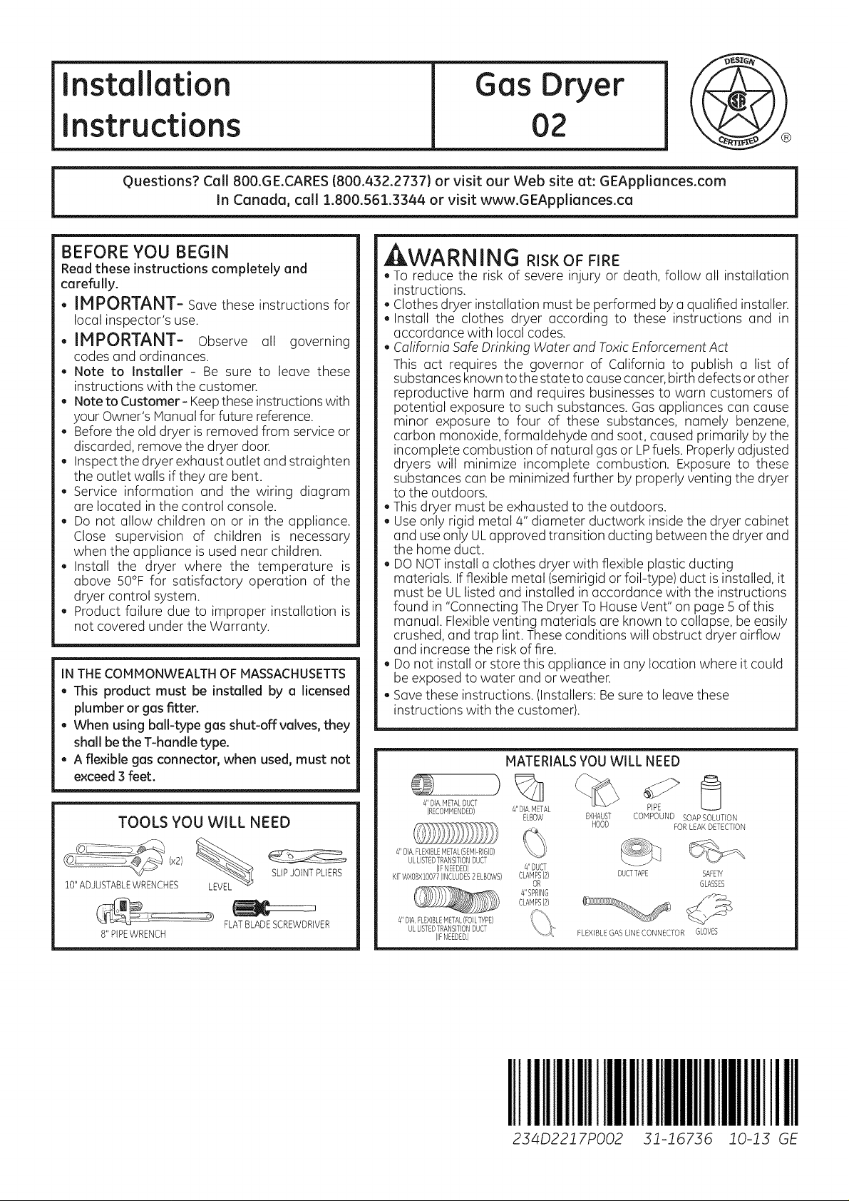
MATERIALSYOUWILL NEED
TOOLS YOU WILL NEED
10"ADJUSTABLEWRENCHES LEV_EL SLIPJOINTPLIERS
8" PIPEWRENCH
FLATBLADESCREWDRIVER
4I1DIA.METALDUCT
(RECOMMENDED)
4HDIA.FLEXIBLEMETAL(SEMI-RIGID)
ULLISTEDTRANSITIONDUCT
KITWX08XI0077(INCLUDES2ELBOVVS}
(IFNEEDED)
4"DIAFLEXIBLEMETAL(FOILTYPE)
ULLISTEDTRANSITIONDUCT
IIFNEEDED)
4"DIAMETAL PIPE
ELBOW EXHAUST COMPOUND SOAP SOLUTION
4"DUCT
CLAMPS(B)
OR
4"SPRING
CLAMPS(2)
IIIIIIIIIIII!11
234D2217P002
HOOD FORLEAKDETECTION
DUCTTAPE SAFETY
FLEXIBLEGASLINECONNECTOR GLOVES
GLASSES
IIII!11111IIII
31-16736 10-13 GE
Page 2
Installation Instructions
Minimum Clearance Other Than Alcove or Closet Installation
Minimum clearance to combustible surfaces and for air opening are: 0 in.clearance both sides and ! in. rear.
Consideration must be given to provide adequate clearance for installation and service.
m PREPARING FOR INSTALLATION
OF NEW DRYER
TIP:Install your dryer before installing your washer.
This will allow better access when installing dryer
exhaust.
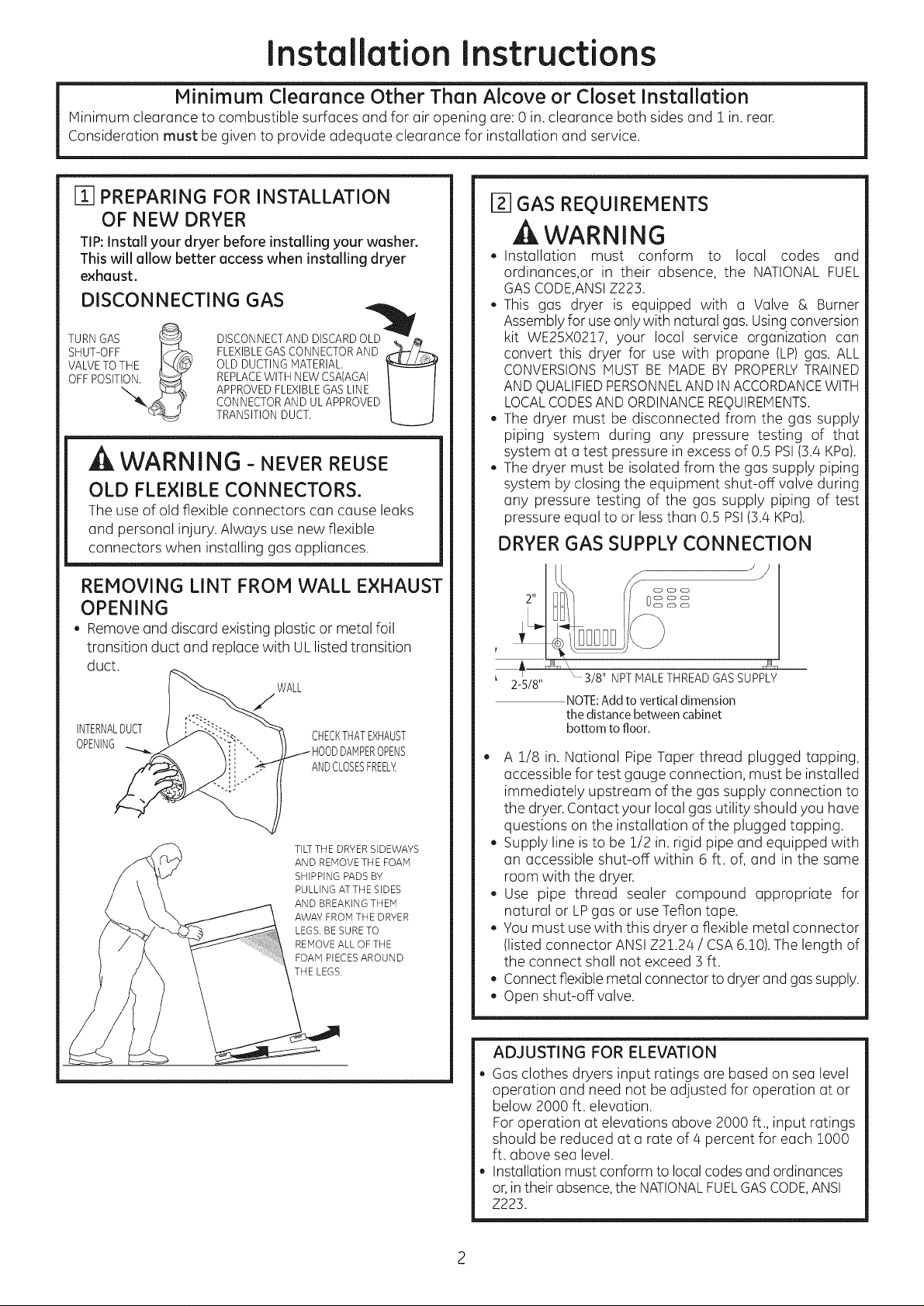
DISCONNECTING GAS
TURN GAS _ DISCONNECTAND DISCARDOku'_ _
SHUT-OFF J¢_ FLEXIBLEGASCONNECTORAND _/_
VALVETOTHE _'_L_ OLD DUCTINGMATERIAL.
APPROVEDFLEXIBLEGASLINE
CONNECTORAND UL APPROVED
TRANSITIONDUCT.
U
WARNING - NEVERREUSE
OLD FLEXIBLE CONNECTORS.
The use of old flexible connectors can cause leaks
and personal injury. Always use new flexible
connectors when installing gas appliances.
REMOVING LINT FROM WALL EXHAUST
OPENING
, Remove and discard existing plastic or metal foil
transition duct and replace with ULlisted transition
duct.
WALL
INTERNALDUCT
OPENING DPENS
CHECKTHATEXHAUST
ANDCLOSESFREELY
TILTTHE DRYERSIDEWAYS
AND REMOVE THE FOAM
SHIPPING PADS BY
PULLING ATTHE SIDES
AND BREAKING THEM
AWAY FROM THE DRYER
LEGS. BESURETO
REMOVEALL OFTHE
FOAM PIECESAROUND
THE LEGS.
12]GAS REQUIREMENTS
WARNING
. Installation must conform to local codes and
ordinances,or in their absence, the NATIONAL FUEL
GASCODE,ANSIZ223.
• This gas dryer is equipped with a Valve & Burner
Assembly for useonly with natural gas. Using conversion
kit WE25X02!7, your local service organization can
convert this dryer for use with propane (LP)gas. ALL
CONVERSIONSMUSTBE MADE BY PROPERLYTRAINED
AND QUALIFIEDPERSONNELAND INACCORDANCEWITH
LOCALCODESANDORDINANCEREQUIREMENTS.
, The dryer must be disconnected from the gas supply
piping system during any pressure testing of that
system at a test pressure inexcess of 0.5 PSI(3.4KPa).
, The dryer must be isolated from the gas supply piping
system by closing the equipment shut-off valve during
any pressure testing of the gas supply piping of test
pressure equal to or less than 0.5 PSI(3.4 KPa).
DRYER GAS SUPPLY CONNECTION
)
2"
2-5/8"
A 1/8 in. National Pipe Taper thread plugged tapping,
accessible for test gauge connection, must be installed
immediately upstream of the gas supply connection to
the dryer. Contact your local gas utility should you have
questions on the installation of the plugged tapping.
, Supply line is to be !/2 in. rigid pipe and equipped with
an accessible shut-off within 6 ft. of, and in the same
room with the dryer.
, Use pipe thread sealer compound appropriate for
natural or LPgas or use Teflon tape.
, You must use with this dryer a flexible metal connector
(listed connector ANSI Z2!.24 / CSA6.!0). The length of
the connect shall not exceed 3ft.
, Connect flexible metal connector to dryer and gassupply.
, Open shut-off valve.
" 3/8" NPT MALETHREAD GAS SUPPLY
NOTE:Add to vertical dimension
the distance between cabinet
bottom to floor,
ADJUSTING FOR ELEVATION
, Gas clothes dryers input ratings are based on sea level
operation and need not be adjusted for operation at or
below 2000 ft. elevation.
Foroperation at elevations above 2000 ft., input ratings
should be reduced at a rate of 4 percent for each 1000
ft. above sea level.
, Installation must conform to local codes and ordinances
or,intheir absence,the NATIONALFUELGASCODE,ANSI
Z223.
Page 3
Installation instructions
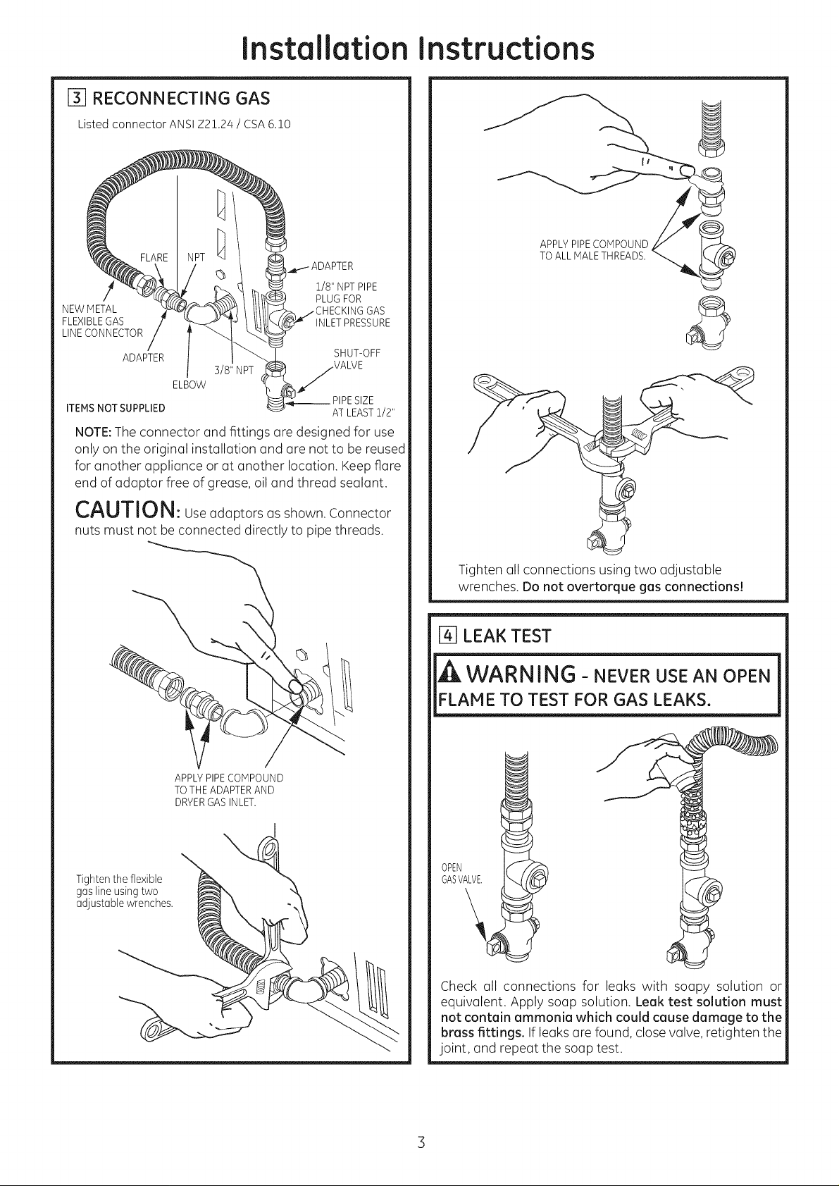
[_ RECONNECTING GAS
Listed connector ANSI Z2!.24 / CSA 6.!0
1/8" NPTPIPE
NEWMETAL GAS
FLEXIBLEGAS INLETPRESSURE
LINECONNECTOR
ADAPTER SHUT-OFF
3/8" NPT
ELBOW
ITEMSNOT SUPPLIED AT LEAST1/2"
NOTE:The connector and fittings ore designed for use
only on the original installation and ore not to be reused
for another appliance or at another location. Keep flare
end of odoptor free of greose, oil ond threod seolont.
PLUGFOR
__ PIPESIZE
APPLYPIPECOMPOUND
TOALL MALETHREADS.
/
CAUTION: UseodoptorsosshownConnector
nuts must not be connected directly to pipe threads.
APPLYPIPECOMPOUND
TOTHEADAPTERAND
DRYERGASINLET.
Tighten the flexible
gas line using two
adjustable wrenches.
Tighten oil connections using two adjustable
wrenches. Do not overtorque gas connections!
[_] LEAK TEST
WARNING- NEVER USE AN OPEN
FLAME TO TEST FOR GAS LEAKS.
GASVALVE.
OPEN
Check oil connections for leaks with soapy solution or
equivalent. Apply soap solution. Leak test solution must
not contain ammonia which could cause damage to the
brass fittings. If leaks ore found, closevalve, retighten the
joint, and repeat the soap test.
Page 4

Installation
Instructions
[] ELECTRICAL CONNECTION
iNFORMATiON
A WARNING - TOREDUCETHE
RISK OF FIRE, ELECTRICAL SHOCK,
AND PERSONAL INJURY:
• DO NOT USE AN EXTENSION CORD
OR AN ADAPTER PLUG WITH THIS
APPLIANCE.
Dryer must be electrically grounded in accordance
with local codes and ordinances, or in the absence
of local codes, in accordance with the NATIONAL
ELECTRICALCODE,ANSI/NFPANO.70.
ELECTRICAL REQUIREMENTS
This appliance must be supplied with 120V, 60Hz, and
connected to a properly grounded branch circuit,
protected by a 15- or 20-amp circuit breaker or time
delay fuse. if electrical supply provided does not meet
the above specifications, it is recommended that a
licensed electrician install an approved outlet.
WARNING - THIS DRYERIS
EQUIPPED WITH A THREE-PRONG
(GROUNDING) PLUG FOR YOUR
PROTECTIONAGAINSTSHOCKHAZARD
AND SHOULD BE PLUGGED DIRECTLY
INTO A PROPERLYGROUNDED THREE-
PRONG RECEPTACLE. DO NOT CUT OR
REMOVE THE GROUNDING PRONG
FROM THIS PLUG.
[_] EXHAUST INFORMATION
WARNING - IN CANADA AND IN
THE UNITED STATES, THE REQUIRED EXHAUST
DUCT DIAMETER IS 4 in (102ram). DO NOT
USE DUCT LONGER THAN SPECIFIED IN THE
EXHAUST LENGTH TABLE.
Using exhaust longer than specified length will:
, Increase the drying times and the energy cost.
, Reducethe dryer life.
, Accumulate lint, creating a potential fire hazard.
Thecorrect exhaust installation is YOURRESPONSIBILITY.
Problems due to incorrect installation are not covered
by the warranty.
Remove and discard existing plastic or metal foil
transition duct and replace with ULlisted transition duct.
The MAXIMUM ALLOWABLEduct length and number of
bends of the exhaust system depends upon the type of
duct, number of turns, the type of exhaust hood (wall
cap), and all conditions noted below. The maximum duct
length for rigid metal duct is shown in the table below.
EXHAUSTLENGTH
RECOMMENDEDMAXIMUM LENGTH
Exhaust Hood Types
Recommended run installations
i @ . 4"°'A_L
NO.of 90° Rigid Rigid
Elbows Metal Metal
0 90 Feet 60 Feet
1 60 Feet 45 Feet
2 45 Feet 35 Feet
3 35 Feet 25 Feet
4 25 Feet 15 Feet
, Forevery extra 90°elbow,reducethe allowable vent system
length by 10 ft.
, Two 45° elbows will be treated likeone 90° elbow.
, Forthe sideexhaust installations, add one 90°elbow to the
chart.
,The total vent system length includes all the straight
portions and elbows of the system (transition duct included).
Use only for short
1/2"
ENSURE PROPER GROUND EXISTS BEFORE USE
LOCAL CODES PERMIT,
q EXTERNALGROUND WIRE
OT PROVIDED), WHICH rV]EETS
)CAL CODES, rvlAYBEADDED
' ATTACHING TO THE GREEN
_OUND SCREW ON THE REAR
: THE DRYER,AND TO A GROUNDED
ETALCOLDWATER PIPE OR OTHER
;TABLISHED GROUND.
EXHAUST SYSTEM CHECK LIST
HOODORWALLCAP
, Terminate in a manner to prevent back drafts or entry of
birdsor other wildlife.
, Termination should present minimal resistance to the
exhaust airflow andshouldrequire littleor no maintenance
to prevent clogging.
, Never install a screen in or over the exhaust duct. This
could cause lint build up.
, Wall caps must be installed at least 12 in. above ground
level or any other obstruction with the opening pointed
down.
SEPARATIONOFTURNS
For best performance, separate allturns by at least 4 ft. of
straight duct, including distance between last turn and
exhaust hood.
TURNSOTHERTHAN90°
, One turn of 450or lessmay be ignored.
, Two 45oturns should be treated as one 90oturn.
, Eachturn over45oshould be treated as one 90oturn.
4
Page 5
Installation
Instructions
SEALING OFJOINTS
, Alljoints should be tight to avoid leaks.The male end of
each section of duct must point away from the dryer.
, The duct shall not be assembled with screws or other
fastening means that extend into the duct and catch
lint.
, Duct joints can be made air and moisture-tight by
wrapping the overlapped joints with duct tape.
, Horizontal runs should slope down toward the outdoors
1//4inch per foot.
INSULATION
Duct work that runs through an unheated area or is near air
conditioning should be insulated to reduce condensation
and lint build-up.
[] EXHAUST CONNECTION
BEFORE PERFORMING THIS EXHAUST
INSTALLATION, BE SURE TO DISCONNECT THE
DRYER FROM ITS ELECTRICAL SUPPLY.
, WARNING - TO REDUCE THE
RISK OF FIRE OR PERSONAL INJURY:
,This clothes dryer must be exhausted to the outdoors.
, Useonly 4" rigid metal ducting for the home exhaust
duct.
,Use only 4" rigid metal or UL-listed flexible metal
(semi-rigid or foil-type) duct to connect the dryer
to the home exhaust duct. It must be installed
in accordance with the instructions found in
"Connecting the Dryer to House Vent" on pages 5-6
of this manual.
, Do not terminate exhaust in a chimney, a wall,
a ceiling, gas vent, crawl space, attic, under an
enclosed floor, or in any other concealed space of
a building. The accumulated lint could create a
potential fire hazard.
,Never terminate the exhaust into a common duct
with a kitchen exhaust system. A combination of
grease and lint creates a potential fire hazard.
, Do not use duct longer than specified inthe exhaust
length table. Longer ducts can accumulate lint,
creating a potential fire hazard.
, Never install a screen in or over the exhaust duct. This
will cause lint to accumulate, creating a potential fire
hazard.
,Do not assemble ductwork with any fasteners
that extend into the duct. These fasteners can
accumulate lint, creating a potential fire hazard.
, Do not obstruct incoming or exhausted air.
, Provide an accessfor inspection and cleaning of the
exhaust system, especially at turns and joints. Exhaust
system shall be inspected and cleaned at least once a
year.
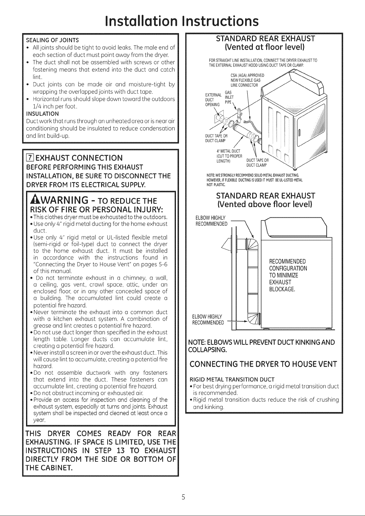
STANDARD REAR EXHAUST
{Vented at floor level}
FORSTRAIGHTLINEINSTALLATION,CONNECTTHEDRYEREXHAUSTTO
THEEXTERNALEXHAUSTHOODUSINGDUCTTAPEORCLAMR
CSA(AGA)APPROVED
NEWFLEXIBLEGAS
LINECONNECTOR
EXTERNAL
DUCT
OPENING
DUCTTAPEOR
DUCTCLAMP
GAS
INLET
4" METALDUCT
(CUTTOPROPER
LENGTH) DUCTTAPEOR
NOTE:WE STRONGLYRECOMMENDSOUDMETALEXHAUSTDUCTING.
HOWEVER,IFFLEXIBLEDUCTINGISUSEDIT MUSTBEUL-LISTEDMETAL
NOTPLASTIC.
DUCTCLAMP
STANDARD REAR EXHAUST
{Vented above floor level}
ELBOWHIGHLY
RECOMMENDED
RECOMMENDED
CONFIGURATION
TOMINIMIZE
EXHAUST
BLOCKAGE.
ELBOWHIGHLY
RECOMMENDED-
NOTE: ELBOWS WILL PREVENT DUCT KINKING AND
COLLAPSING.
CONNECTING THE DRYERTO HOUSE VENT
RIGIDMETALTRANSITION DUCT
, For best drying performance, a rigid metal transition duct
is recommended.
, Rigid metal transition ducts reduce the risk of crushing
and kinking.
THIS DRYER COMES READY FOR REAR
EXHAUSTING. IF SPACE IS LIMITED, USE THE
INSTRUCTIONS IN STEP 13 TO EXHAUST
DIRECTLY FROM THE SIDE OR BOTTOM OF
THE CABINET.
Page 6

Installation Instructions
UL-LISTED FLEXIBLE METAL (SEMI-RIGID) TRANSITION
DUCT
, If rigid met(]l duct c(]nnot be used, then UL-listed flexible
met(]l (semi-rigid) ducting can be used (KitWX08X10077).
, Never install flexible met(]l duct in w(]lls, ceilings, floors or
other enclosed sp(]ces.
,Total length of flexible metal duct should not exceed 8 feet
(2.4m).
, Form(]ny (]pplic(]tions, inst(]lling elbows (It both the dryer
(]nd the w(]ll is highly recommended (see illustr(]tions
below). Elbows (]llow the dryer to sit close to the w(]ll
without kinking (]nd or crushing the tr(]nsition duct,
m(]ximizing drying Derform(]nce.
,Avoid resting the duct on sh(]rp objects.
UL-LISTEDFLEXIBLEMETAL(FOIL-TYPE)TRANSITIONDUCT
, In speciol installations, it may be necessary to connect the
dryer to the housevent usingo flexible metol (foil-type)duct.
A UL-listedflexible metol (foil-type)duct moy be used ONLY
in instollotions where rigid metol or flexible metol (semi-rigid)
ducting cannot be used AND where a 4" diameter con be
mointoinedthroughout the entire lengthof thetransition duct.
, In Conodo ond the United Stotes, only the flexible metol
(foil-type) ducts thot comply with the "Outline for Clothes
Dryer Tronsition Duct Subject 2158A" sholl be used.
, Never instoll flexibl_ metol duct in wolls, ceilings, floors or
other enclosed sp(]ces.
,TotGI length of flexible metol duct should not exceed 8 feet
(2.4m).
, Avoid resting the duct on shGrpobjects.
For best drying performonce:
1.Slide one end of the duct over the clothes dryer outlet pipe.
2.Secure the duct with o clomp.
3.With the dryer in its permGnent position, extend the duct
to its full length. Allow 2" of duct to overlGp the exhGust
pipe. Cut off ond remove excess duct. Keep the duct os
stroight os possible for moximum oirflow.
4.Securethe duct to the exh(]ust pipe with the other cl(]mp.
LEVELING DRYER
LEVEL
FRONTT0-BACK,
4LEVELINGLEGS
LEVEL
SIDE-TO-SIDE,
L
STANDTHEDRYERUPRIGHTNEARTHE
FINALLOCATIONANDADJUSTTHE4LEVELING
LEGSTOMATCHTHEHEIGHTOFYOURWASHER,
ADJUSTTHE2ANTI-TIPLEGSTOCONTACT
THEFLOOR,
ALCOVE OR CLOSET INSTALLATION
, If your dryer is (]pproved for inst(]ll(]tion in (in (]lcove or
closet, it will be stated on o I(]bel on the dryer b(]ck.
,The dryer MUST be vented to the outdoors. See the
EXHAUSTINFORMATIONstep 6.
,Minimum clear(]nce between dryer c(]binet (]nd
(]dj(]cent w(]lls or other surf(Ices is:
0 in. either side
3 in.front
3 in. re(it
, Minimum vertic(]l sp(]ce from floor to overhead c(]binets,
ceiling, etc. is 52 in.
, Closet doors must be Iouvered or otherwise ventil(]ted
(]nd must cont(]in (] minimum of 60 sq. in. of open (]re(]
equ(]lly distributed. If the closet cont(]ins both (] w(]sher
(]nd (] dryer, doors must cont(]in (] minimum of 120 sq.
in. of open (]re(] equ(]lly distributed.
,The closet should be vented to the outdoors to prevent
g(]s pocketing in c(]se of (] g(]s le(]k in the supply line.
, No other fuel-burning (]ppli(]nce sh(]ll be inst(]lled in the
s(]me closet with the dryer.
2ANTI-TIPLEGS
[] BATHROOM OR BEDROOM
INSTALLATION
,The dryer MUSTbevented to the outdoors. SeeEXHAUST
INFORMATIONstep 6.
, The inst(]ll(]tion must conform with Ioc(]l codes or, in the
(]bsence of Ioc(]l codes, with the NATIONALELECTRICAL
CODE,ANSI/NFPANO.70.
6
Page 7

Installation instructions
[] MOBILE OR MANUFACTURED HOME
INSTALLATION
.Installation must conform to the MANUFACTURED
HOMECONSTRUCTION& SAFETYSTANDARD,TITLE24,
PART32-80 or, when such standard is not applicable,
with AMERICAN NATIONAL STANDARD FOR MOBILE
HOME,ANSI/NFPANO.501B.
.The dryer MUSTbe vented to the outdoors with the
termination securely fastened to the mobile home
structure. (SeeEXHAUSTINFORMATIONsection 6).
.The vent MUSTNOTbe terminated beneath a mobile or
manufactured home.
.The vent duct material MUSTBEMETAL.
.KIT 14-D346-33 MUST be used to attach the dryer
securely to the structure.
.The vent MUST NOTbe connected to any other duct,
vent, or chimney.
. Donot usesheet metal screws or other fastening devices
which extend into the interior of the exhaust vent.
. Provide an opening with a free area of at least 25 sq. in.
for introduction of outside air into the dryer room.
.Stacking of a gas dryer is not permitted in a mobile
home or manufactured home.
r_ GARAGE INSTALLATION (IF ALLOWED
BY LOCAL CODES)
. Dryers installed in garages must be elevated 18 inches
(46cm) above the floor.
[_ DRYER EXHAUST TO LEFT OR
BOTTOM
, ,WAR NING- BEFOREPERFORMING
THIS EXHAUST INSTALLATION, BE SURE
TO DISCONNECT THE DRYER FROM ITS
ELECTRICAL SUPPLY. PROTECT YOUR
HANDS AND ARMS FROM SHARP EDGES
WHEN WORKING INSIDE THE CABINET.
BESURE TO WEAR GLOVES.
TAB LOCATION
BENDTAB
Up/45°
Through the rear opening, locate the tab in the middle of
the appliance base. Lift the tab to about 450 using a flat
blade screwdriver.
ADDING NEW DUCT
FIXING
HOLE
Reconnect the cut portion (A) of the duct to the blower
housing. Make sure that the fixing hole is aligned with the
tab in the base. Use the screw saved previously to secure
the duct in place through the tab on the appliance base.
PORTION"A"
LEFTSIDE
EXHAUST
ADDING ELBOW AND DUCT FOR
EXHAUST TO LEFT SIDE OF CABINET
. Preassemble 4" elbow with 4"duct. Wrap duct tape
around joint.
. Insert duct assembly, elbow first, through the side
opening and connect the elbow to the dryer internal
duct.
REMOVE
SCREW
AND SAVE,
Detach and remove the bottom or left side knockout as
desired. Removethe screw inside the dryer exhaust duct
and save.Pullthe duct out of the dryer. Protect sharp edges
around the knockout and exhaust opening with the tape.
FIXINGHOLE
I-' 9"
Cut the duct as shown and keep portion A.
CAUTION: Besure not to pullor damage the
electrical wires inside the dryer when inserting the duct.
DUCT
TAPE
. Apply duct tape as shown on the joint between the
dryer internal duct and the elbow.
DUCT CAUTION:
Internal duct joints must be
secured with tape, otherwise
they may separate and cause a
_ safety hazard.
Page 8

Installation
Instructions
ADDING ELBOW FOR EXHAUST
THROUGH BOTTOM OF CABINET
, Insert the elbow through the rear opening and connect
itto the dryer internal duct.
,Apply duct tope on the joint between the dryer internal
duct and elbow, as shown above.
ADDING COVER PLATE TO REAR OF
CABINET
Connect standard metal elbows and ducts to complete
the exhaust system. Cover back opening with a plate
(KitWEIM454) available from your local service provider.
Placedryer in final location.
CAUTION:
Internal duct joints must be secured with tape,
otherwise they may separate and cause a
safety hazard.
LOOSEN EACH TOP HINGE
SCREW HALF WAY AND LIFT
THE DOOR UP AND OFF
3. Removethe blind plate from
the hinge side of the dryer
by removing its two screws.
Removethe strike plate from
the opposite side ofthe dryer
by removing its two screws, pLATE
Reinstall the plates, on the
opposite sides, using two
screws in each plate.
4.Rotate the door 1800. Insert the door on the opposite
side of the opening by moving the door ON and DOWN
until the top hinge and the bottom hinge are resting on
the top screws inserted in step 1.
TON TOP HINGESCREWS
PLATE
(KITWE1M454)
,iI_WARNING-NEVER LEAVE THE
BACK OPENING WITHOUT THE PLATE
{KIT WEIM454).
114]CHANGINGDIRECTIONOFDOOROPENING
1.Open the door and remove the filler plugs opposite the
hinges. With the door completely open, remove the
bottom screw from each hinge on the dryer face. Insert
these screws about half way into the TOPholes, for each
hinge on the opposite side (where you removed the filler
plugs). Apply firm pressure to get the screws started.
REMOVE 4 PLUGS AND KEEP
FOR INSERTION INTO
THE OPPOSITE SIDE
REMOVEBOTTOMSCREWFROMEACHHINGE
AND INSTALL HALF WAY INTO EACH TOP OF
//
ROTATE DOOR 180 ° AND HANG
5.Remove the remaining screws from the side of the
opening from which the door was removed. With these
screws secure each hinge at the bottom. Tighten the
two top screws oneach hinge. Reinsert the plastic plugs
on the side from which the door was removed.
INSTALLANDTIGHTEN BOTTOM INSERT PLUGS
SCREWS AND TIGHTEN TOP INTO HOLES ON
_._OPPOSITE SIDE
SERVICING
WARN !NG-LABEL ALL WIRES PRIOR
TO DISCONNECTING WHEN SERVICING
CONTROLS. WIRING ERRORS CAN CAUSE
IMPROPER AND DANGEROUS OPERATION
AFTER SERVICI NG/I NSTALLATION.
2. Loosen the top screw from each hinge on the dryer face
halfway. With one hand holding the top of the door and
the other hand holding the bottom, remove the door
from the dryer by lifting it UP and OFF.
REGISTERYOUR NEW APPLIANCE TO RECEIVE
ANY IMPORTANTPRODUCT NOTIFICATIONS.
Please go to www.GEAppliunces.com or mail in
your product registration card.
For questions on installation, call: 800.626.2000 (US)or
800-561-3344 (Canada).
8
 Loading...