

Page 1
,ns,o,,o,ion! Gos yer1@
Instructions
Questions on Installation? Call: 800.GE.CARES (US) or 800-561-3344 (Canada) I
or visit our web site at: www.GEAppliances.corn (US)
I
BEFORE YOU BEGIN
Readthese instructions
completely and carefully.
• IMPORTANT- save
these instructions for local
inspector's use.
• IMPORTANT- Observe
all governing codes and
ordinances.
• Note to Installer - Besure to
leave these instructions with
the customer.
• Note to Customer- Keepthese
instructions with your Owner's
Hanual for future reference.
• Before the old dryer isremoved
from service or discarded,
remove the dryer door.
• Inspect the dryer exhaust
outlet and straighten the
outlet walls if they are bent.
• Service information and the
wiring diagram are located in
the control console.
WARNING RISKOF FIRE
• To reduce the risk of severe injury or death, follow all installation instructions.
• Clothes dryer installation must be performed by aqualified installer.
• Install the clothes dryer according to these instructions and in accordance with local
codes.
• California Safe Drinking Water and Toxic Enforcement Act
This act requires the governor of California to publish a list of substances known to the
state to cause cancer, birth defects or other reproductive harm and requires businesses
to warn customers of potential exposure to such substances. Gas appliances can
cause minor exposure to four of these substances, namely benzene, carbon monoxide,
formaldehyde and soot, caused primarily by the incomplete combustion of natural gas
or LPfuels. Properly adjusted dryers will minimize incomplete combustion. Exposure to
these substances can beminimized further by properly venting the dryer to the outdoors.
• This dryer must be exhausted to the outdoors.
• Use only rigid metal 4" diameter ductwork inside the dryer cabinet and use only UL
approved transition ducting between the dryer and the home duct.
• DONOTinstall a clothes dryer with flexible plastic ducting materials. If flexible metal
(semirigid or foil-type) duct is installed, it must be UL listed and installed in accordance
with the instructions found in "Connecting The Dryer To House Vent" on page 5 of this
manual. Flexible venting materials are known to collapse, be easily crushed, and trap
lint. These conditions will obstruct dryer airflow and increase the risk of fire.
• Do not install or store this appliance inany location where it could be exposed to water
and or weather.
• Save these instructions. (Installers: Besure to leave these instructions with the
customer).
• Do not allow children on
or in the appliance. Close
supervision of children is
necessary when the appliance
is used near children.
• Install the dryer where the
• This product must be instolled bg e licensed plumber or gos fitter.
• When using bell-tgpe gos shut-off velves, theg shell be the T-hendle tgpe.
• A flexible gos connector, when used, most not exceed 3feet.
temperature is above 50°F for
satisfactory operation of the
dryer control system.
• Product failure due to
improper installation isnot
covered under the Warranty.
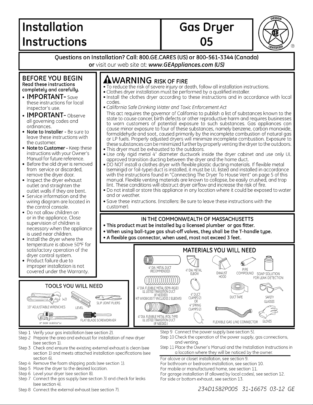
TOOLS YOU WILL NEED
10"ADJUSTABLEWRENCHES
R" PlP_ \AIP_EIF'H
Step i
Verify your gas installation (see section 2).
Step 2
Prepare the area and exhaust for installation of new dryer
(seesection 1).
Step 3
Check and ensure the existing external exhaust is clean (see
section 1)and meets attached installation specifications (see
section 6).
Step 4
Remove the foam shipping pads (see section 1).
Step 5
Move the dryer to the desired location.
Step 6
Level your dryer (see section 8).
Step 7
Connect the gas supply (seesection 3) and check for leaks
(seesection 4).
Connect the external exhaust (seesection 7).
Step 8
(x2)
FLATBLADESCREWDRIVER
SLIPJOINTPLIERS
IN THE COMMONWEALTH OF MASSACHUSETTS
MATERIALS YOU WILL NEED
%
4"DIA.METALDUCT
(RECOMMENDED}
4"DIA.FLEXIBLEMETALISEMI-RIGID}
ULLISTEDTRANSITIONDUCT
KiTWXO8X10077(INCLUDES2ELBOWS}
4"DIA.FLEXIBLEMETAL(FOILTYPE}
(LFNEEDED}
ULLISTEDTRANSiTiONDUCT
(IFNEEDED,}
Step 9 Connect the power supply (see section 5).
Step 10Check the operation of the power supply, gas connections,
Step 11Place the Owner's Manual and the Installation Instructions in
For alcove or closet installation, see section 9.
For bathroom or bedroom installation, see section 10.
For mobile or manufactured home, see section 11.
For garage installation (ifallowed by local codes), see section 12.
For side or bottom exhaust, see section 13.
4"DIA.METAL
ELBOW
4"DUCT
CLAMPS(2}
OR
4"SPRING
CLAMPS(2}
and venting.
a location where they will be noticed by the owner.
EXHAUST
HOOD
FLEXIBLEGASLINECONNECTOR GLOVES
COHPOUND SOAPSOLUTION
DUCTTAPE SAFETY
234D1582PO05 31-16675 03-12 GE
PIPE
FORLEAKDETECTION
GLASSES
Page 2
Installation Instructions
Minimum Clearance Other Than Alcove or Closet Installation
Minimum clearance to combustible surfaces and for air opening are: 0 in.clearance both sides and 1 in. rear.Consideration
must be given to provide adequate clearance for installation and service.
[] PREPARING FOR INSTALLATION
OF NEW DRYER
TIP:Install your dryer before installing your washer.
This will allow better access when installing dryer
exhaust.
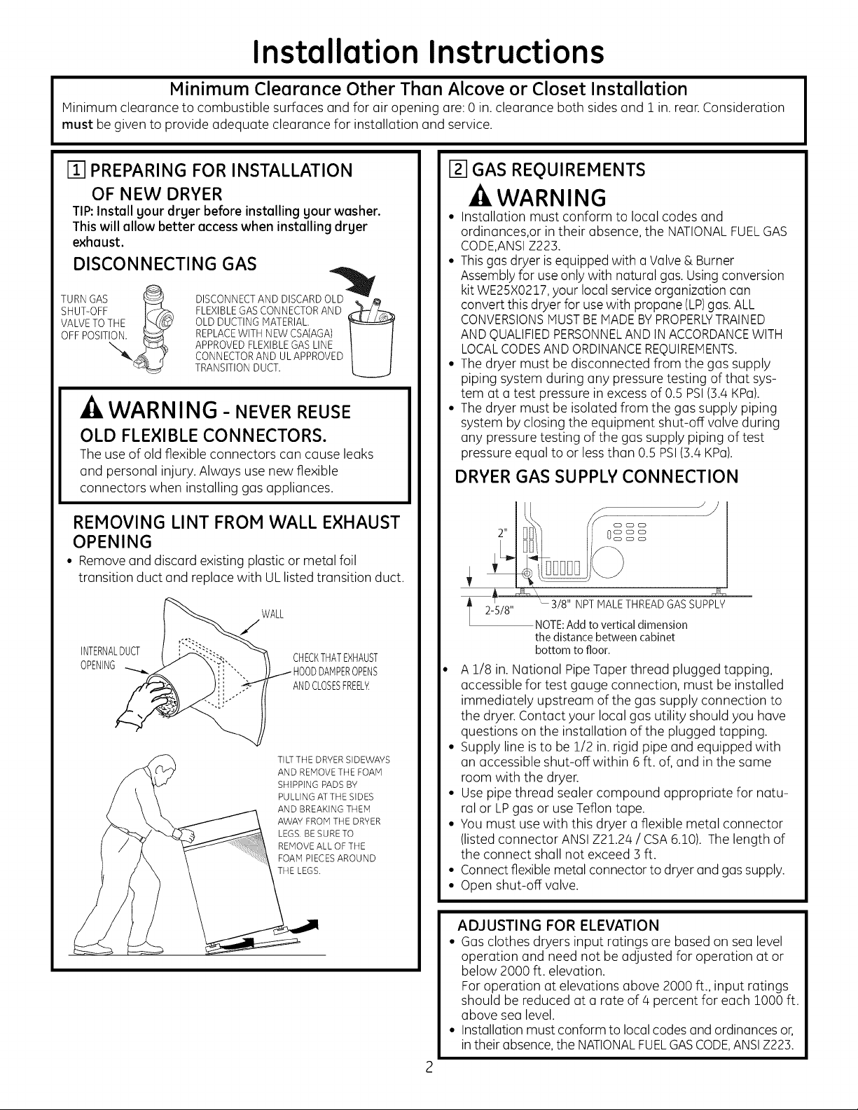
DISCONNECTING GAS
TURNGAS _ DISCONNECTANDDISCARDOLu4_ _
SHUT-OFF I_}"_ FLEXIBLEGASCONNECTORAND ,_
VALVETOTHE _,_ OLD DUCTINGMATERIAL.
OFF O . .o.
APPROVEDFLEXIBLEGASLINE
CONNECTORAND UL APPROVED
TRANSITIONDUCT.
U
WARNING - NEVERREUSE
OLD FLEXIBLE CONNECTORS.
The use ofold flexible connectors can cause leaks
and personal injury. Always use new flexible
connectors when installing gas appliances.
REMOVING LINT FROM WALL EXHAUST
OPENING
• Remove and discard existing plastic or metal foil
transition duct and replace with ULlisted transition duct.
[] GAS REQUIREMENTS
-4,WARNING
• Installation must conform to local codes and
ordinances,or in their absence, the NATIONALFUELGAS
CODE,ANSIZ223.
• This gas dryer isequipped with aValve & Burner
Assembly for useonly with natural gas. Using conversion
kit WE25X0217,your local service organization can
convert this dryer for use with propane (LP)gas. ALL
CONVERSIONSMUSTBEMADEBYPROPERLYTRAINED
AND QUALIFIEDPERSONNELAND INACCORDANCEWITH
LOCALCODESAND ORDINANCEREQUIREMENTS.
• The dryer must be disconnected from the gas supply
piping system during any pressure testing of that sys-
tem at a test pressure in excess of 0.5 PSI(3.8 KPa).
• The dryer must be isolated from the gas supply piping
system by closing the equipment shut-off valve during
any pressure testing of the gas supply piping of test
pressure equal to or less than 0.5 PSI(3.4 KPa).
DRYER GAS SUPPLY CONNECTION
INTERNALDUCT
OPENING
WALL
CHECKTHATEXHAUST
.I HOODDAMPEROPENS
ANDCLOSESFREEL_
TILTTHE DRYERSIDEWAYS
AND REMOVETHE FOAM
SHIPPING PADSBY
PULLING ATTHE SIDES
AND BREAKING THEM
AWAY FROMTHE DRYER
LEGS. BE SURE TO
REMOVEALL OF THE
FOAM PIECESAROUND
THE LEGS.
2-5/8"
A 1/8 in. National Pipe Taper thread plugged tapping,
accessible for test gauge connection, must be installed
immediately upstream of the gas supply connection to
the dryer.Contact your local gas utility should you have
questions onthe installation of the plugged tapping.
• Supply line is to be 1/2 in.rigid pipe and equipped with
an accessible shut-off within 6ft. of, and inthe same
room with the dryer.
• Use pipe thread sealer compound appropriate for natu-
ral or LPgas or use Teflon tape.
• You must use with this dryer aflexible metal connector
(listed connector ANSIZ21.28 / CSA6.10). The length of
the connect shall not exceed 3 ft.
• Connectflexible metal connector to dryer and gassupply.
• Open shut-off valve.
ADJUSTING FOR ELEVATION
• Gas clothes dryers input ratings are based on sea level
operation and need not be adjusted for operation at or
below 2000 ft. elevation.
For operation at elevations above 2000 ft., input ratings
should bereduced at a rate of 4 percent for each lO00 ft.
above sea level.
• Installation must conform to local codes and ordinances or,
in their absence,the NATIONALFUELGASCODE,ANSIZ223.
"- 3/8" NPTMALE THREADGAS SUPPLY
NOTE:Add to vertical dimension
the distance between cabinet
bottom to floor.
Page 3
Installation Instructions
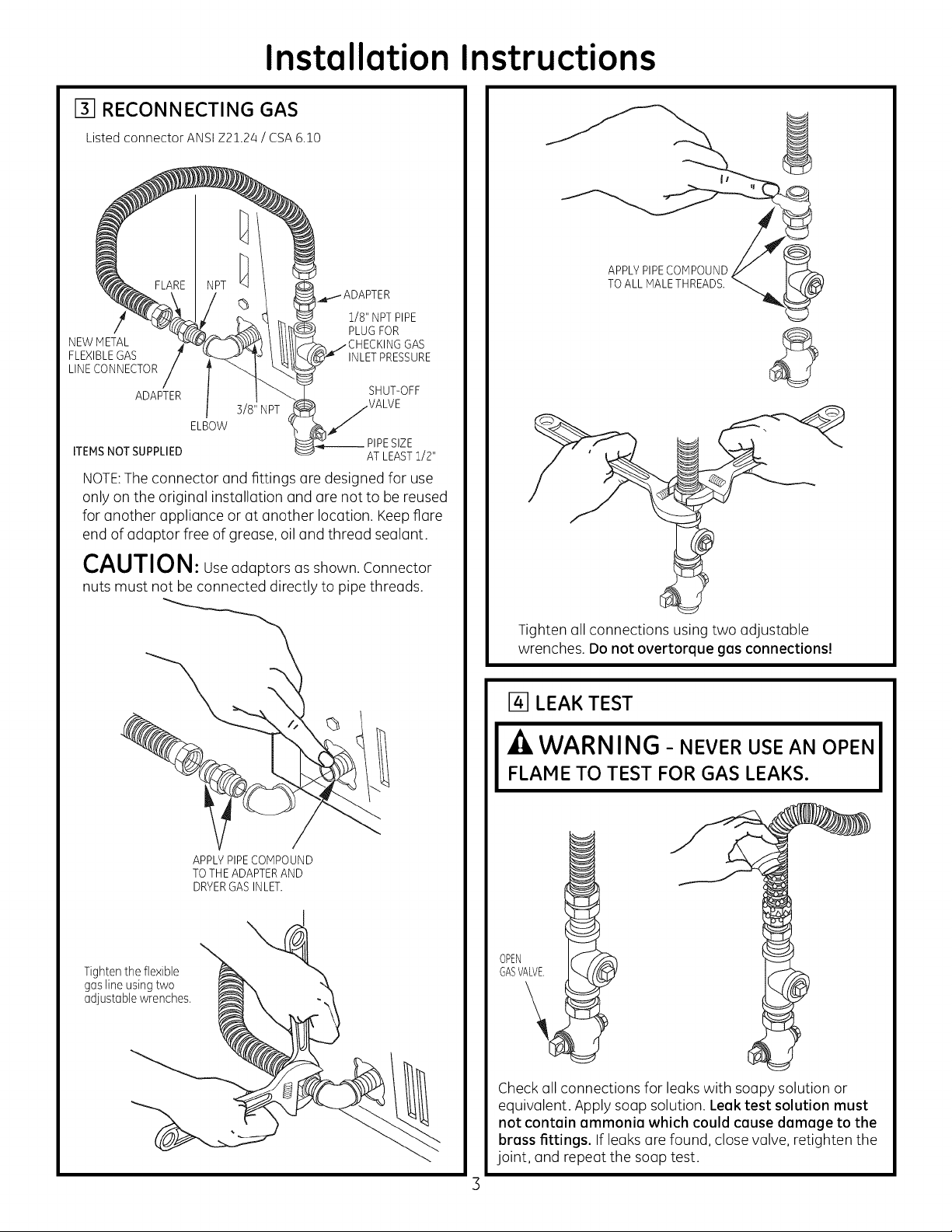
r3] RECONNECTING GAS
Listed connector ANSI Z2!.24 / CSA 6.!0
1/8" NPTPIPE
NEWMETAL GAS
FLEXIBLEGAS INLETPRESSURE
LINECONNECTOR
ADAPTER SHUT-OFF
3/8" NPT VALVE
ELBOW
ITEMSNOT SUPPLIED AT LEAST1/2"
NOTE:The connector ond fittings (]re designed for use
only on the originol instollotion ond (]re not to be reused
for onother opplionce or ot onother Iocotion. Keepfiore
end of °doptor free of greose, oil ond threod seolont.
PLUGFOR
__ PIPESIZE
I
APPLYPIPECOMPOUND
TOALL MALETHREADS.
CAUTION: UseodoptorsosshownConnector
nuts must not be connected directly to pipe threads.
\
APPLYPIPECOMPOUND
TOTHE ADAPTERAND
DRYERGASINLET.
Tighten the flexible
gas line using two
adjustable wrenches.
Tighten oil connections using two adjustable
wrenches. Do not overtorque gas connections!
14] LEAK TEST
_ZlWARNING- NEVER USE AN OPEN
FLAME TO TEST FOR GAS LEAKS.
GASVALVE.
OPEN
Check all connections for leaks with soupy solution or
equivalent. Apply soup solution. Leek test solution must
not contain ammonia which could cause damage to the
brass fittings. Ifleaks are found, close valve, retighten the
joint, and repeat the soup test.
Page 4

Installation Instructions
151ELECTRICALCONNECTION INFORMATION
WARNING - TOREDUCETHE
RISK OF FIRE, ELECTRICAL SHOCK, AND
PERSONAL INJURY:
• DO NOT USE AN EXTENSION CORD
OR AN ADAPTER PLUG WITH THIS
APPLIANCE.
Dryer must be electrically grounded in accordance
with local codes and ordinances, or in the absence
of local codes, in accordance with the NATIONAL
ELECTRICALCODE,ANSI/NFPANO.70.
ELECTRICAL REQUIREMENTS
This appliance must be supplied with 120V, 60Hz, end
connected to o properlg grounded branch circuit, pro-
tected by e 15- or 20-amp circuit breaker or time deleg
fuse. If electrical supplg provided does not meet the
above specifications, it is recommended that a licensed
electrician install an approved outlet.
.ZkWARNING - THISDRYERIS
EQUIPPED WITH A THREE-PRONG
(GROUNDING) PLUG FOR YOUR
PROTECTION AGAINST SHOCK HAZARD
AND SHOULD BE PLUGGED DIRECTLY
INTO A PROPERLY GROUNDED THREE-
PRONG RECEPTACLE. DO NOT CUT OR
REMOVE THE GROUNDING PRONG
FROM THIS PLUG.
[] EXHAUST INFORMATION
,AWARNING -IN CANADAANDINTHE
UNITED STATES, THE REQUIRED EXHAUST
DUCT DIAMETER IS 4in (102mm). DO NOT
USE DUCT LONGER THAN SPECIFIED IN THE
EXHAUST LENGTH TABLE.
Using exhaust longer than specified length will:
• Increase the drying times and the energy cost.
• Reduce the dryer life.
• Accumulate lint, creating a potential fire hazard.
The correct exhaust installation is YOUR
RESPONSIBILITY.Problems due to incorrect
installation are not covered by the warrantg.
Remove and discard existing plastic or metal foil
transition duct and replace with UL listed transition duct.
The MA×IMUM ALLOWABLE duct length and number of
bends of the exhaust system depends upon the type of
duct, number of turns, the type of exhaust hood (wall
cap), and all conditions noted below. The maximum duct
length for rigid metal duct isshown in the table below.
EXHAUST LENGTH
RECOMMENDEDMAXIMUM LENGTH
No. of 90 °
Elbows
0
]
2
3
4
Exhaust Hood Types
Recommended run installations
Rigid
Metal
90 Feet
60 Feet
/45 Feet
35 Feet
25 Feet
Use only for short
4" DIA.
Rigid
Metal
60 Feet
/45 Feet
35 Feet
25 Feet
15 Feet
ENSURE PROPER GROUND EXISTS BEFORE USE
IF LOCAL CODES PERMIT,
AN EXTERNALGROUND WIRE
(NOT PROVIDED),WHICH MEETS
LOCAL CODES, MAY BEADDED
BYATTACHING TO THE GREEN
GROUND SCREWON THE REAR
OF THE DRYER,AND TO A GROUNDED
METAL COLD WATER PIPEOR OTHER
ESTABLISHED GROUND.
EXHAUST SYSTEM CHECK LIST
HOOD OR WALL CAP
• Terminate in a manner to prevent back drafts or entry of
birds or other wildlife.
• Termination should present minimal resistance to
the exhaust air flow and should require little or no
maintenance to prevent clogging.
• Never install a screen in or over the exhaust duct. This
could cause lint build up.
• Wall caps must be installed at least ]2 in. above ground
level or any other obstruction with the opening pointed
down.
SEPARATIONOFTURNS
For best performance, separate all turns by at least/4 ft.
of straight duct, including distance between last turn and
exhaust hood.
TURNSOTHERTHAN 90°
• One turn of/45oor less may be ignored.
• Two/450 turns should be treated as one 900turn.
• Eachturn over/450 should be treated as one 900 turn.
Page 5

Installation Instructions
SEALING OFJOINTS
• Alljoints should be tight to avoid leaks.The male end of
each section of duct must point away from the dryer.
• The duct shall not be assembled with screws or other
fastening means that extend into the duct and catch lint.
• Ductjoints can be made air and moisture-tight by
wrapping the overlapped joints with duct tape.
• Horizontal runs should slope down toward the outdoors
1/4 inch per foot.
INSULATION
Duct work that runs through an unheated area or is
near air conditioning should be insulated to reduce
condensation and lint build-up.
I--1-1EXHAUST CONNECTION
BEFORE PERFORMING THIS EXHAUST
INSTALLATION, BE SURE TO DISCONNECT THE
DRYER FROM ITS ELECTRICAL SUPPLY.
- WARNING - TO REDUCE THE RISK
OF FIRE OR PERSONAL INJURY:
•This clothes dryer must be exhausted to the outdoors.
• Use only 4" rigid metal ducting for the home exhaust
duct.
• Use only 4" rigid metal or UL-listed flexible metal (semi-
rigid or foil-type) duct to connect the dryer to the home
exhaust duct. It must be installed in accordance with
the instructions found in "Connecting the Dryer to
House Vent" on pages 5-6 of this manual.
• Do not terminate exhaust ina chimney, a wall, a ceiling,
gas vent, crawl space, attic, under an enclosed floor,
or in any other concealed space of a building. The
accumulated lint could create a potential fire hazard.
• Never terminate the exhaust into a common duct with
a kitchen exhaust system. A combination of grease and
lint creates a potential fire hazard.
• Do not use duct longer than specified in the exhaust
length table. Longer ducts can accumulate lint, creating
a potential fire hazard.
• Never install a screen in or over the exhaust duct. This
will cause lint to accumulate, creating a potential fire
hazard.
• Do not assemble ductwork with any fasteners that
extend into the duct. These fasteners can accumulate
lint, creating a potential fire hazard.
• Do not obstruct incoming or exhausted air.
• Provide an access for inspection and cleaning of the
exhaust system, especially at turns and joints. Exhaust
systemshallbe inspected and cleaned atleastonce a year.
THIS DRYER CONES READY FOR REAR EX-
HAUSTING. IF SPACE IS LIMITED, USE THE
INSTRUCTIONS IN STEP 13 TO EXHAUST
DIRECTLY FROM THE SIDE OR BOTTOM
OF THE CABINET.
STANDARD REAR EXHAUST
(Vented at floor level)
FORSTRAIGHTLINEINSTALLATION,CONNECTTHEDRYEREXHAUSTTO
THEEXTERNALEXHAUSTHOODUSINGDUCTTAPEORCLAMR
CSA(AGA)APPROVED
NEWFLEXIBLEGAS
LINECONNECTOR
EXTERNALINLET
DUCT PIPE
OPENING
DUCTTAPEOR
DUCTCLAMP
ELBOWHIGHLY
RECOMMENDED
ELBOWHIGHLY
RECOMMENDED---
NOTE: ELBOWS WILL PREVENT DUCT KINKING AND
COLLAPSING.
CONNECTING THE DRYERTO HOUSE VENT
RIGID METALTRANSITION DUCT
• For best drying performance, a rigid metal transition duct
is recommended.
• Rigidmetal transition ducts reduce the riskof crushing and
kinking.
GAS
4"METALDUCT
(CUTTOPROPER
LENGTH) DUCTTAPEOR
NOTE:WESTRONGLY RECOMMEND SOLIDMETAL EXHAUSTDUCTING.
HOWEVER,IF FLEXIBLEDUCTINGIS USEDIT MUSTBEUL-LISTEDMETAL
NOTPLASTIC.
DUCTCLAMP
STANDARD REAR EXHAUST
(Vented above floor level)
RECOMMENDED
CONFIGURATION
TOMINIMIZE
EXHAUST
BLOCKAGE.
Page 6
Installation Instructions
UL-LISTEDFLEXIBLEMETAL(SEMI-RIGID)TRANSITIONDUCT
• If rigid metal duct cannot be used, then UL-listed flexible
metal (semi-rigid) ducting can be used (Kit WX08X10077).
• Never install flexible metal duct in walls, ceilings, floors or
other enclosed spaces.
•Totallength offlexiblemetalduct should not exceed8feet (2.4m).
• For many applications, installing elbows at both the dryer
and the wall is highly recommended (see illustrations
below). Elbows allow the dryer to sit close to the wall
without kinking and or crushing the transition duct,
maximizing drying performance.
•Avoid resting the duct on sharp objects.
UL-LISTEDFLEXIBLEMETAL(FOIL-TYPE)TRANSITIONDUCT
• In special installations, it may be necessaryto connect the
dryer to the housevent using a flexible metal (foil-type)duct.
A UL-listed flexible metal (foil-type)duct may be used ONLY
in installations where rigid metal or flexible metal (semi-rigid)
ducting cannot be used AND where a 4" diameter can be
maintained throughout the entire length of the transition duct.
• In Canada and the United States, only the flexible metal
(foil-type) ducts that comply with the "Outline for Clothes
Dryer Transition Duct Subject 2158A" shall be used.
• Never install flexible metal duct in walls, ceilings, floors or
other enclosed spaces.
•Totallength offlexiblemetalduct should not exceed8feet (2.4m).
• Avoid resting the duct on sharp objects.
For best drying performance:
1.Slide one end of the duct over the clothes dryer outlet pipe.
2.Secure the duct with a clamp.
3.With the dryer in its permanent position, extend the duct
to its full length. Allow 2" of duct to overlap the exhaust pipe.
Cut off and remove excess duct. Keep the duct as straight
as possible for maximum airflow.
4.Secure the duct to the exhaust pipe with the other clamp.
ELBOWHIGHLY
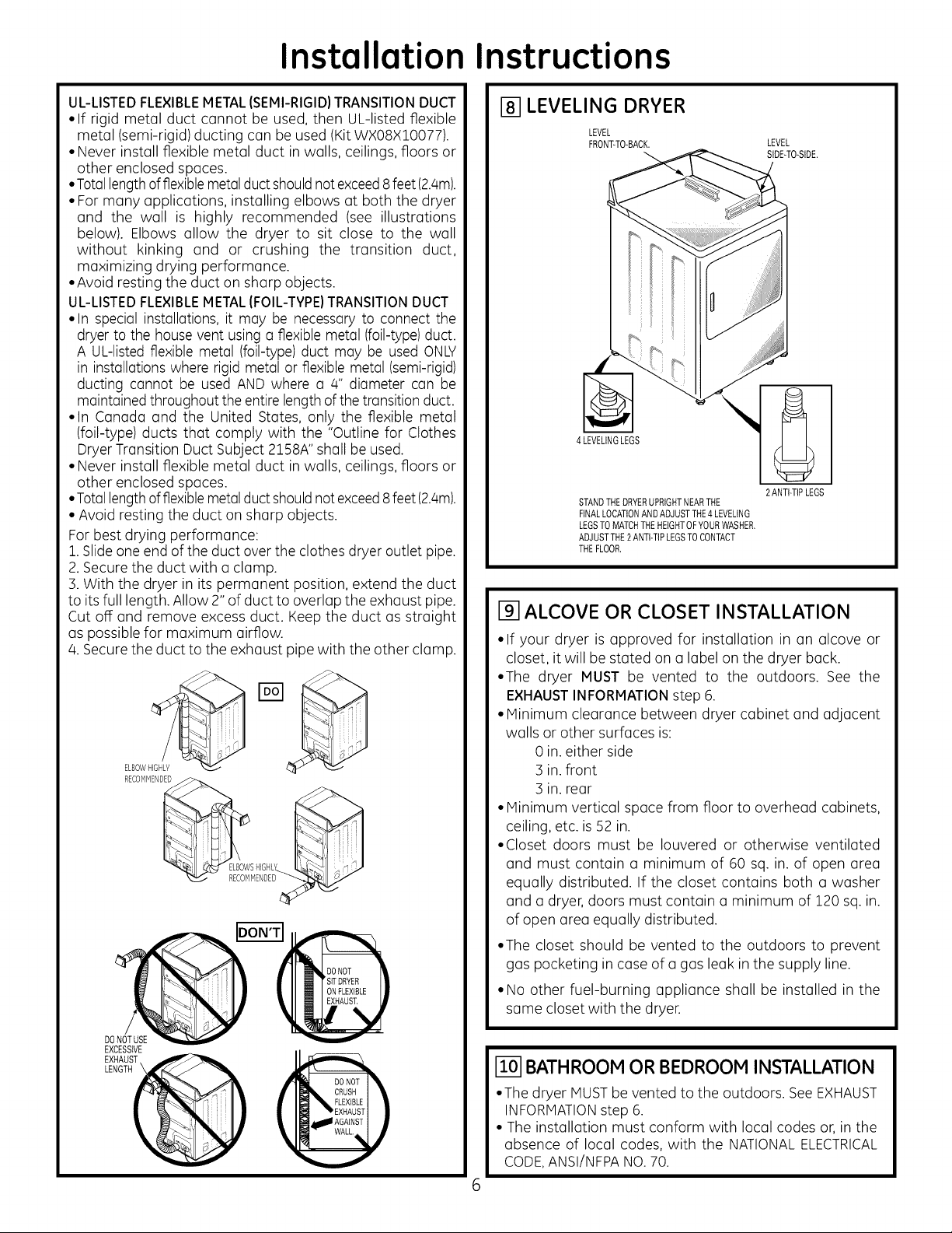
[] LEVELING DRYER
LEVEL
FRON_TO-BACK.
4 LEVELINGLEGS
STANDTHEDRYERUPRIGHTNEARTHE
FINALLOCATIONANDADJUSTTHE4LEVELING
LEGSTOMATCHTHEHEIGHTOFYOURWASHER,
ADJUSTTHE2ANTI-TIPLEGSTOCONTACT
THEFLOOR,
LEVEL
SIDE-TO-SIDE,
2 ANTI-TIPLEGS
[] ALCOVE OR CLOSET INSTALLATION
• If your dryer is approved for installation in an alcove or
closet, it will be stated on a label on the dryer back.
• The dryer MUST be vented to the outdoors. See the
EXHAUST INFORMATION step 6.
• Minimum clearance between dryer cabinet and adjacent
walls or other surfaces is:
0 in. either side
3 in. front
3 in. rear
• Minimum vertical space from floor to overhead cabinets,
ceiling, etc. is 52 in.
• Closet doors must be Iouvered or otherwise ventilated
and must contain a minimum of 60 sq. in. of open area
equally distributed. If the closet contains both a washer
and a dryer, doors must contain a minimum of 120 sq. in.
of open area equally distributed.
• The closet should be vented to the outdoors to prevent
gas pocketing in case of a gas leak in the supply line.
• No other fuel-burning appliance shall be installed in the
same closet with the dryer.
DO
EXCESSIVE
_EXNHATUHS__
[] BATHROOM OR BEDROOM INSTALLATION
•The dryer MUSTbe vented to the outdoors. SeeEXHAUST
INFORMATIONstep 6.
• The installation must conform with local codes or, in the
absence of local codes, with the NATIONALELECTRICAL
CODE,ANSI/NFPANO.70.
Page 7

Installation Instructions
[] MOBILE OR MANUFACTURED HOME
INSTALLATION
• Installation must conform to the MANUFACTUREDHOME
CONSTRUCTION& SAFETY STANDARD,TITLE 24, PART
:32-80 or, when such standard is not applicable, with
AMERICAN NATIONAL STANDARD FOR MOBILE HOME,
ANSI/NFPANO.501B.
•The dryer MUST be vented to the outdoors with the
termination securely fastened to the mobile home
structure. (SeeEXHAUSTINFORMATIONsection 6).
•The vent MUST NOT be terminated beneath a mobile or
manufactured home.
•The vent duct material MUSTBEMETAL.
• KIT14-D346-33 MUSTbeusedto attach the dryer securely
to the structure.
•Thevent MUSTNOTbe connected to any other duct, vent,
or chimney.
• Do not use sheet metal screws or other fastening devices
which extend into the interior of the exhaust vent.
• Provide an opening with a free area of at least 25 sq. in.
for introduction of outside air into the dryer room.
•Stacking of a gas dryer is not permitted in a mobile home
or manufactured home.
I_l GARAGE INSTALLATION (IF ALLOWED
BY LOCAL CODES)
• Dryers installed in garages must be elevated 18 inches
(46cm) above the floor.
TAB LOCATION
BENDTAB
UP45°
Through the rear opening, locate the tab in the middle of
the appliance base. Lift the tab to about 450 using a flat
blade screwdriver.
ADDING NEW DUCT
FIXING
HOLE
PORTION"A" _..
[] DRYER EXHAUST TO LEFT OR BOTTOM
-tlLWARNING - BEFOREPERFORMING
THIS EXHAUST INSTALLATION, BE SURE
TO DISCONNECT THE DRYER FROM ITS
ELECTRICAL SUPPLY. PROTECT YOUR
HANDS AND ARMS FROM SHARP EDGES
WHEN WORKING INSIDE THE CABINET.
BESURE TO WEAR GLOVES.
REMOVE
SCREW
AND SAVE,
C %MZo o Sdp
(ONEONLY),
Detach and remove the bottom or left side knockout as
desired. Removethe screw inside the dryer exhaust duct
and save. Pullthe duct out ofthe dryer. Protect sharp edges
around the knockout and exhaust opening with the tape.
FIXINGHOLEs
LEFTSIDE
EXHAUS]
Reconnect the cut portion (A)of the duct to the blower
housing. Make sure that the fixing hole is aligned with the
tab inthe base. Use the screw saved previously to secure
the duct in place through the tab on the appliance base.
ADDING ELBOW AND DUCT FOR
EXHAUST TO LEFT SIDE OF CABINET
• Preassemble 4" elbow with 4" duct. Wrap duct tape
around joint.
• Insert duct assembly, elbow first, through the side
opening and connect the elbow to the dryer internal duct.
CAUTION: Be sure not to pullor damage the
electrical wires inside the dryer when inserting the duct.
DUCT
TAPE
Cut the duct as shown and keep portion A.
Page 8

Installation Instructions
• Apply duct tape as shown on the joint between the dryer
internal duct and the elbow.
DUCT
,TAPE
CAUTION:
Internal duct joints must be
secured with tape, otherwise
theg mag separate and cause a
safetg hazard.
ADDING ELBOW FOR EXHAUST THROUGH
BOTTOM OF CABINET
• Insert the elbow through the rear opening and connect it
to the dryer internal duct.
•Apply duct tape on the joint between the dryer internal
duct and elbow, as shown above.
k
I_ CHANGING DIRECTION OF DOOR
OPENING
REMOVE/4HOLEPLUGSAND
REMOVE/4 PLACETHEMINTHEHOLES
HINGESCREWS. ONTHEOPPOSITESIDE.
ROTATEDOOR180°
ANDREINSTALL.
CAUTION:
Internal duct joints must be secured with tape,
otherwise they may separate and cause a
safety hazard.
ADDING COVER PLATE TO REAR OF
CABINET
"-.-.'-4 ,_a,'-"_
"'"_'" ";'9
÷ .÷
÷
PLATE
(KITWE1M454)
Connect standard metal elbows and ducts to complete
the exhaust system. Cover back opening with a plate (Kit
WEllV]454) available from your local service provider. Place
dryer in final location.
1_-51SERVICING
-_WARN ING-LABEL ALL WIRES
PRIOR TO DISCONNECTING WHEN
SERVICING CONTROLS. WIRING
ERRORS CAN CAUSE IMPROPER AND
DANGEROUS OPERATION AFTER
SERVICING/INSTALLATION.
REGISTER YOUR NEW APPLIANCE TO RECEIVE ANY
IMPORTANT PRODUCT NOTIFICATIONS.
-_WARNING-NEVER LEAVE THE
BACK OPENING WITHOUT THE PLATE
(KIT WEIM454).
Please go to www.GEAppliances.com or moil in
your product registration card.
For questions on installation, call: 800.626.2000 (US)or
800-561-3344 (Canada).
 Loading...