

Page 1
Installation
ElectricDryer
Instructions
Questions? Call 800.GE.CARES {800.432.2737) or visit our Web site at: GEAppliances.com
I
BEFORE YOU BEGIN
Read these instructions completely and
carefully.
, IMPORTANT- savethese instructions
for local inspector's use.
, IMPORTANT- Observe all governing
codes and ordinances.
, Note to Installer - Besure to leave these
instructions with the customer.
, Note to Customer Keep these
instructions with your Owner's Manual for
future reference.
, Before the old dryer is removed from
service or discarded, remove the dryer
door.
, Serviceinformation and the wiring diagram
are located in the control console.
, Donot allow children on or in the appliance.
Close supervision of children is necessary
when the appliance is used near children.
, Install the dryer where the temperature is
above 50°F for satisfactory operation of
the dryer control system.
, Product failure due to improper installation
is not covered under the Warranty.
In Canada, call 1.800.561.3344 or visit www.GEApplionces.co I
01
WARNING RISK OF FIRE
, To reduce the risk of severe injury or death, follow all installation
instructions.
, Clothes dryer installation must beperformed by a qualified installer.
, Install the clothes dryer according to these instructions and in
accordance with local codes.
, Thisdryer must be exhausted to the outdoors.
, Useonly rigid metal 4" diameter ductwork insidethe dryercabinet and use
only ULapproved transition ducting betweenthe dryer and the home duct.
, DO NOTinstall a clothes dryer with flexible plastic ducting materials.
If flexible metal (semi-rigid or foil-type) duct is installed, it must be
UL listed and installed in accordance with the instructions found in
"Connecting The Dryer To House Vent" on pages 4-5 of this manual.
Flexible venting materials are known to collapse, be easily crushed,
and trap lint. These conditions will obstruct dryer airflow and increase
the risk of fire.
, Do not install or store this appliance in any location where it could be
exposed to water and or weather.
, Save these instructions. (Installers: Be sure to leave these instructions
with the customer).
NOTE: Installation and service of this dryer requires basic
mechanical and electrical skills. It is your responsibility to
contact a qualified installer to make the electrical connections.
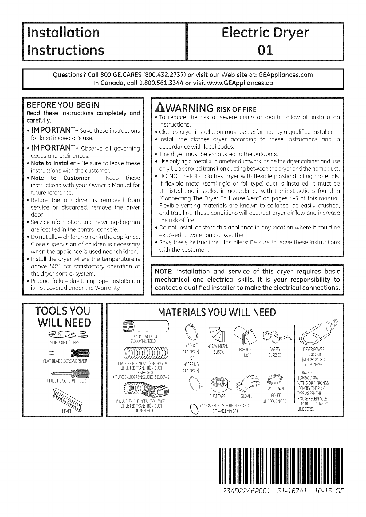
TOOLSYOU
WILL NEED
SLIPJOINTPLIERS
FLATBLADESCREWDRIVER
PHILLIPSSCREWDRIVER
MATERIALSYOUWILL NEED
)
4"DIA.METALDUCT
(RECOMMENDED)
4"DIA,FLEXIBLEMETAL(SEMPRIGD)
ULLISTEDTRANSITIONDUCT
KITWXO8X!O077(INCLUDES2ELBOWS)
4"DIA,FLEXIBLEMETAL(FOILTYPE)
(IFNEEDED)
ULLISTEDTRANSITIONDUCT
(IFNEEDED,)
4"DUCT
CLAMPS(2)
OR
#'SPRING
CLAMPS(2)
%
4"DIA,METAL
ELBOW
DUCTTAPE
EXHAUST SAFETY
HOOD GLASSES
GLOVES
%
3/4"STRAIN
RELIEF
ULRECOGNIZED
DRYERPOWER
CORDKIT
(NOTPROVIDED
WITHDRYER)
ULRATED
!20/240V,30A
WITH] OR4PRONGS,
IDENTIFYTHEPLUG
TYPEASPERTHE
HOUSERECEPTACLE
BEFOREPURCHASING
LINECORD,
IIII!1111111111111111111111111111111
234D2246PO01 31-16741 i0-13 GE
Page 2
Installation instructions
Minimum Clearance Other Than Alcove or Closet Installation
Minimum clearance to combustible surfaces and for air opening are: 0 in.clearance both sides and 1in. rear.
Consideration must be given to provide adequate clearance for installation and service.
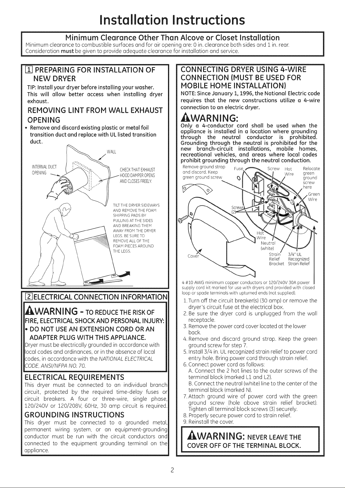
[] PREPARING FOR INSTALLATION OF
NEW DRYER
TIP:Install your dryer before installing your washer.
This will allow better access when installing dryer
exhaust.
REMOVING LINT FROM WALL EXHAUST
OPENING
• Remove and discard existing plastic or metal foil
transition duct and replace with ULlisted transition
duct.
WALL
INTERNALDUCT
OPENING HOODDAMPEROPENS
CHECKTHATEXHAUST
ANDCLOSESFREEL_
TILTTHE DRYER SIDEWAYS
AND REMOVETHE FOAM
SHIPPING PADS BY
PULLING ATTHE SIDES
AND BREAKING THEM
AWAY FROM THE DRYER
LEGS. BE SURE TO
REMOVEALL OF THE
FOAM PIECESAROUND
THE LEGS.
CONNECTING DRYER USING 4-WIRE
CONNECTION {MUST BE USED FOR
MOBILE HOME INSTALLATION)
NOTE:Since January 1, 1996, the National Electric code
requires that the new constructions utilize a 4-wire
connection to an electric dryer.
At WARNING:
Only a 4-conductor cord shall be used when the
appliance is installed in a location where grounding
through the neutral conductor is prohibited.
Grounding through the neutral is prohibited for the
new branch-circuit installations, mobile homes,
recreational vehicles, and areas where local codes
prohibit grounding through the neutral conduction.
Remove ground strap Fuse _Screw Hot Relocate
and discard. Keep hK_ __ _ Wire green
green ground screw eaJ X_I_/ ground
. . _ screw
_"__ _._..._X here
\ \ \ Hot",,,/ /'-l J" r
)ve*r'_ I Relief Recognized
[]_]ELECTRICALCONNECTION INFORMATION
WARNING - ToREDUCETHERISKOF
FIRE, ELECTRICAL SHOCK AND PERSONAL iNJURY:
, DO NOT USE AN EXTENSION CORD OR AN
ADAPTER PLUG WITH THiS APPLIANCE.
Dryer must be electrically grounded in accordance with
local codes and ordinances, or in the absence of local
codes, in accordance with the NATIONALELECTRICAL
CODE,ANSI/NFPANO. 70.
ELECTRICAL REQUIREMENTS
This dryer must be connected to an individual branch
circuit, protected by the required time-delay fuses or
circuit breakers. A four or three-wire, single phase,
120/240V or 120/208V, 60Hz, 30 amp circuit is required.
GROUNDING INSTRUCTIONS
This dryer must be connected to a grounded metal,
permanent wiring system, or an equipment-grounding
conductor must be run with the circuit conductors and
connected to the equipment grounding terminal on the
appliance.
_-_Z:_ Bracket Strain Relief
/4#ZO AWG minimum copper conductors or 120/2/40V 30A power
supply cord kit marked for usewith dryers and provided with closed
loop or spade terminals with upturned ends (not supplied).
1.Turn off the circuit breaker(s)(30 amp) or remove the
dryer's circuit fuse at the electrical box.
2.Be sure the dryer cord is unplugged from the wall
receptacle.
3.Removethe power cord cover located at the lower
back.
4.Remove and discard ground strap. Keep the green
ground screw for step 7.
5.Install 3/4 in. ULrecognized strain relief to power cord
entry hole. Bring power cord through strain relief.
6.Connect power cord as follows:
A. Connect the 2 hot lines to the outer screws of the
terminal block (marked L1and L2).
B.Connect the neutral (white) line to the center of the
terminal block (marked N).
7.Attach ground wire of power cord with the green
ground screw (hole above strain relief bracket).
Tighten all terminal block screws (3)securely.
8. Properly secure power cord to strain relief.
9.Reinstall the cover.
,dELW_K|_|r_!o: NEVER LEAVE THE
COVER OFF OF THE TERMINAL BLOCK.
Page 3
Installation instructions
CONNECTING DRYER USING 3-WIRE
CONNECTION
If required, by local code, install external
ground (not provided) to grounded metal,
cold water pipe, or other established
ground determined by a qualified
electrician. Fuse
Green Ground
Screw
Strap
Cover
3 #10 AWG minimum copper conductors or 120/2a0v 30A power
supply cord kit marked for usewith dryers and provided with closed
loop or spade terminals with upturned ends (not supplied).
3-wire Connection
Not for use in Canada.
DONOTuse for Mobile Home Installations.
NOTfor use on new construction.
NOTfor use on recreational vehicles.
NOTfor use in ureas where local codes prohibit grounding
through the neutral conduction.
!. Turn off the circuit breaker(s) (30amp) or remove the
dryer's circuit fuse at the electrical box.
2. Besure the dryer cord is unplugged from the wall.
3. Remove the power cord cover located at the lower
back.
4. Install 3/a in. ULrecognized strain relief to power cord
entry hole. Bring power cord through strain relief.
5. Connect power cord us follows:
A. Connect the 2 hot lines to the outer screws of the
terminal block (marked L! and L2).
B.Connect the neutral (white) line to the center of
the terminal block (marked N).
6. Be sure ground strap is connected to neutral (center)
terminal of block and to green ground screw on
cabinet rear. Tighten all terminal block screws (3)
securely.
7. Properly secure power cord to strain relief.
8. Reinstall the cover.
,_W/AK|'_||'_: NEVER LEAVE THE
COVER OFF OF THE TERHINAL BLOCK.
Screw Hot
Wire
Strain
Relief
Bracket
Wire
3/4" UL
Recognized
Strain Relief
_] EXHAUST INFORMATION
, WARN ING -IN CANADA AND IN THE
UNITED STATES,THE REQUIRED EXHAUST DUCT
DIAMETER IS4 in(102mm).DO NOT USE DUCT
LONGER THAN SPECIFIEDINTHE EXHAUST
LENGTH TABLE.
Usingexhaust longer than specified length will:
, Increasethe drying times andthe energycost.
, Reducethe dryer life.
, Accumulate lint, creating a potential fire hazard.
Thecorrect exhaust installation is YOURRESPONSIBILITY.
Problems dueto incorrect installation are not covered by
the warranty.
Removeand discard existing plastic or metal foil transition
duct and replacewith ULlisted transition duct.
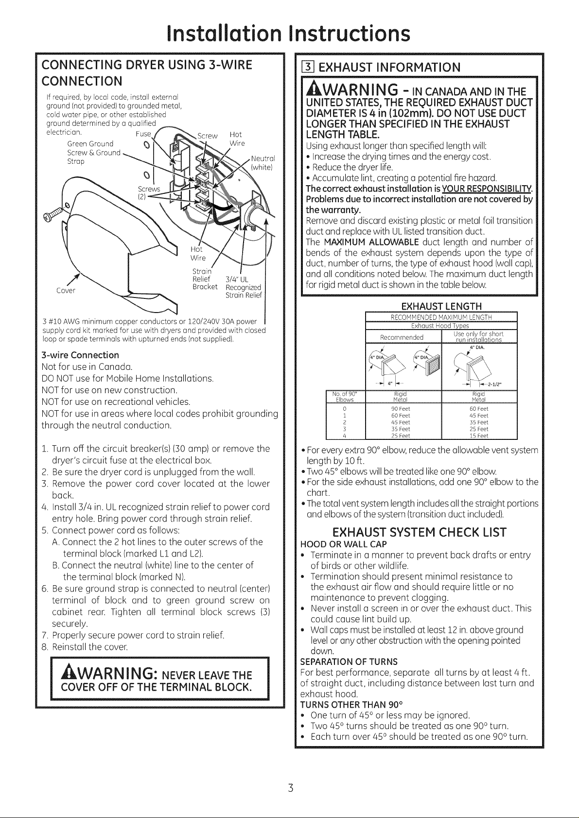
The MAXIMUM ALLOWABLEduct length and number of
bends of the exhaust system depends upon the type of
duct, number of turns, the type of exhaust hood (wallcap),
and all conditions noted below.The maximum duct length
for rigid metal duct isshown inthe table below.
EXHAUST LENGTH
RECOMMENDEDMAXIMUM LENGTH
Exhaust Hood Types
Recommended run installations
" _ 112"
No. of 90 ° Rigid Rigid
Elbows Metal Metal
0 90 Feet 60 Feet
i 60 Feet 45 Feet
2 45 Feet 35 Feet
3 35 Feet 25 Feet
4 25 Feet 15 Feet
, Forevery extra 90° elbow,reduce the allowable vent system
length by 10ft.
, Two 45°elbows will betreated likeone 90°elbow.
, Forthe side exhaust installations,add one 90° elbow to the
chart.
, Thetotal vent system length includes allthe straight portions
and elbowsof the system (transitionduct included).
EXHAUST SYSTEM CHECK LIST
HOOD OR WALL CAP
, Terminate in a manner to prevent back drafts or entry
of birds or other wildlife.
, Termination should present minimal resistance to
the exhaust air flow and should require little or no
maintenance to prevent clogging.
, Never install a screen in or over the exhaust duct. This
could cause lint build up.
, Wall capsmust be installed at least12 in. above ground
levelor any other obstruction with the opening pointed
down.
SEPARATIONOFTURNS
For best performance, separate all turns by at least 4 ft.
of straight duct, including distance between last turn and
exhaust hood.
TURNSOTHERTHAN 90°
, One turn of 450 or lessmay be ignored.
, Two 450turns should be treated as one 900 turn.
, Eachturn over 450 should be treated as one 900 turn.
Use only for short
Page 4

Installation
Instructions
SEALING OFJOINTS
, Alljoints should be tight to avoid leaks.The male end of
each section of duct must point away from the dryer.
, The duct shall not be assembled with screws or other
fastening means that extend into the duct and catch
lint.
, Duct joints can be made air and moisture-tight by
wrapping the overlapped joints with duct tape.
, Horizontal runs should slope down toward the outdoors
1/4 inch per foot.
INSULATION
Duct work that runs through an unheated areaor isnear air
conditioning should be insulated to reduce condensation
and lint build-up.
[-_ EXHAUST CONNECTION
kWARNING - TO REDUCE THE
RISK OF FIRE OR PERSONAL INJURY:
,This clothes dryer must be exhausted to the outdoors.
, Use only 4" rigid metal ducting for the home exhaust
duct.
,Use only 4" rigid metal or UL-listed flexible metal
(semi-rigid or foil-type) duct to connect the dryer
to the home exhaust duct. It must be installed
in accordance with the instructions found in
"Connecting the Dryer to House Vent" on pages 4-5
of this manual.
,Do not terminate exhaust in a chimney, a wall,
a ceiling, gas vent, crawl space, attic, under an
enclosed floor, or in any other concealed space
of a building. The accumulated lint could create a
potential fire hazard.
,Never terminate the exhaust into a common duct
with a kitchen exhaust system. A combination of
grease and lint creates a potential fire hazard.
, Do not use duct longer than specified in the exhaust
length table. Longer ducts can accumulate lint,
creating a potential fire hazard.
, Never install a screen inor over the exhaust duct. This
will cause lint to accumulate, creating a potential fire
hazard.
, Do not assemble ductwork with any fasteners that
extend into the duct.These fasteners can accumulate
lint, creating a potential fire hazard.
, Do not obstruct incoming or exhausted air.
,Provide an access for inspection and cleaning of
the exhaust system, especially at turns and joints.
Exhaust system shall be inspected and cleaned at
least once a year.
THIS DRYER COMES READY FOR REAR
EXHAUSTING. IF SPACE IS LIMITED,
USE THE INSTRUCTIONS IN STEP 10 TO
EXHAUST DIRECTLY FROM THE SIDES OR
THE BOTTOM OF THE CABINET.
STANDARD REAR EXHAUST
(Vented at floor level}
Forstraight line installation, connect
the dryer exhaust to the external
exhaust hood using duct tape or
clamp.
EXTERNALDUCT
DUCTTAPEOR
DUCTCLAMP
4" METAL DUCTCUT
TO PROPERLENGTH
DUCTTAPEOR
DUCTCLAMP
NOTE: WE STRONGLYRECOMMENDSOU
METALEXHAUSTDUCTING. HOWEVER,II
FLEXIBLEDUCTINGISUSEDITMUSTBE
UL-LISTEDMETAL,NOT PLASTIC.
STANDARD REAR EXHAUST
{Vented above floor level)
ELBOWHIGHLY
RECOMMENDED
RECOMMENDED
CONFIGURATION
TOMINIMIZE
EXHAUST
BLOCKAGE.
ELBOWHIGHLY
RECOMMENDED-
NOTE: ELBOWS WILL PREVENT DUCT
KINKING AND COLLAPSING.
CONNECTING THE DRYERTO HOUSE VENT
RIGID METALTRANSITION DUCT
, Forbest drying performance, a rigid metal transition duct
is recommended.
, Rigid metal transition ducts reduce the risk of crushing
and kinking.
UL-LISTEDFLEXIBLEMETAL(SEMI-RIGID}TRANSITIONDUCT
, If rigid metal duct cannot be used, then UL-listed flexible
metal (semi-rigid) ducting can be used (Kit WXO8X10077).
, Never install flexible metal duct in walls, ceilings, floors or
other enclosed spaces.
, Total length of flexible metal duct should not exceed 8
feet (2.4m).
4
Page 5

Installation instructions
, For many applications, installing elbows at both the dryer
and the wall is highly recommended (see illustrations
below). Elbows allow the dryer to sit close to the wall
without kinking and or crushing the transition duct,
maximizing drying performance.
, Avoid resting the duct on sharp objects.
UL-LISTEDFLEXIBLEMETAL(FOIL-TYPE}TRANSITIONDUCT
, In special installations, it may be necessary to connect
the dryer to the house vent using a flexible metal (foil-
type) duct. A UL-listed flexible metal (foil-type) duct may
be used ONLYin installations where rigid metal or flexible
metal (semi-rigid) ducting cannot be used AND where
a 4" diameter can be maintained throughout the entire
length of the transition duct.
, In Canada and the United States, only the flexible metal
(foil-type) ducts that comply with the "Outline for Clothes
Dryer Transition Duct Subject 2158A" shall be used.
, Never install flexible metal duct in walls, ceilings, floors
or other enclosed spaces.
, Total length of flexible metal duct should not exceed 8
feet (2.4m).
, Avoid resting the duct on sharp objects.
For best drying performance
1 Slide one end of the duct over the clothes dryer outlet
pipe.
2.Secure the duct with a clamp.
3.With the dryer in its permanent position, extend the duct
to its full length. Allow 2" of duct to overlap the exhaust
pipe. Cut off and remove excess duct. Keep the duct as
straight as possible for maximum airflow.
4.Secure the duct to the exhaust pipe with the other clamp.
I_]LEVELING AND STABILIZING YOUR
DRYER
Stand the dryer upright near the final location and adjust
the 4 leveling legs,at the corners, to ensure that the dryer
is level from side to side and front to rear.
LEVEL
FRONT-TO-BACK, LEVEL
"-_. SIDE-TO-SI[
ELBOWHIGHLY
RECOMMENDED
DONOTUSE
EXCESSIVE
EXHAUST
LENGTH \
DONOT
CRUSH
ALCOVE OR CLOSET INSTALLATION
, If your dryer isapproved for installation in an alcove or
closet, it will be stated on a label onthe dryer back.
.The dryer MUST be vented to the outdoors. See the
EXHAUSTINFORMATIONsections 3 & 4.
.Minimum clearance between dryer cabinet and
adjacent walls or other surfaces is:
0 in. either side
3 in. front
3 in. rear
,Hinimum vertical space from floor to overhead
cabinets, ceiling, etc. is 52 in.
, Closet doors must be Iouvered or otherwise ventilated
and must contain a minimum of 60 sq. in.of open area
equally distributed. If the closet contains both a washer
and a dryer, doors must contain a minimum of 120 sq.
in. of open area equally distributed.
Page 6

Installation
Instructions
_7 BATHROOM OR BEDROOM iNSTALLATION
.ThedryerMUST beventedtotheoutdoors.See EXHAUST
INFORMATION section3 &4.
. The installation must conform with local codes or,in the
absence of local codes, with the NATIONALELECTRICAL
CODE,ANSI/NFPANO.70.
[87MOBILE OR MANUFACTURED HOME
INSTALLATION
.Installation must conform to the MANUFACTURED
HOME CONSTRUCTION& SAFETYSTANDARD,TITLE24,
PART32-80 or, when such standard is not applicable,
with AMERICAN NATIONAL STANDARD FOR MOBILE
HOME,ANSI/NFPANO.50lB.
.The dryer MUST be vented to the outdoors with the
termination securely fastened to the mobile home
structure. (SeeEXHAUSTINFORMATIONsection 3 & 4).
.The vent MUSTNOTbe terminated beneath a mobile or
manufactured home.
.The vent duct material MUSTBEMETAL.
. Do not use sheet metal screwsor other fastening devices
which extend into the interior of the exhaust vent.
. See section 2for electrical connection information.
[_]GARAGE INSTALLATION {IF ALLOWED
BY LOCAL CODES}
. Dryers installed in garages must be elevated 18 inches
(46cm) above the floor.
FIXINGHOLE
B A
Cut the duct as shown and keepportion A.
TAB LOCATION
BENDTAB
UP45 o
Through the rear opening, locate the tab in the middle of
the appliance base. Liftthe tab to about 450using a flat
blade screwdriver.
ADDING NEW DUCT
FIXING
HOLE
PORTION"A"
_07DRYER EXHAUST TO RIGHT, LEFT OR
BOTTOM CABINET
AWARNING - BEFOREPERFORMING
THiS EXHAUST iNSTALLATiON, BE SURE
TO DISCONNECT THE DRYER FROM iTS
ELECTRICAL SUPPLY. PROTECT YOUR
HANDS AND ARMS FROM SHARP EDGES
WHEN WORKING INSIDE THE CABINET.
BE SURE TO WEAR GLOVES.
REMOVE
SCREW
ANDSAVE
REMOVEDESIRED
KNOCKOUT(ONEONLY).
Detach and remove the bottom, right or left side knockout
as desired. Remove the screw inside the dryer exhaust duct
and save. Pull the duct out of the dryer.
RIGHTOR
LEETSIDE
EXHAUST
Reconnectthe cut portion (A)of the duct to the blower
housing. Make surethat the shortened duct isaligned with
the tab inthe base. Usethe screw saved previouslg to secure
the duct inplace throuqh the tab on the appliance base.
6
Page 7

Installation instructions
ADDING ELBOW AND DUCT FOR
EXHAUST TO LEFT OR RIGHT SIDE OF
CABI NET
. Preassemble 4"elbow with 4" duct. Wrap duct tape
around joint.
* Insert duct assembly, elbow first, through the side
opening and connect the elbow to the dryer internal
duct.
ACAUTION: Be sure nottopullordamage the
electrical wires inside the dryer when inserting the duct.
EXHAUSTCAN
BEADDEDTO
LEFTORRIGHTSIDE
DUCT
TAPE
ADDING COVER PLATE TO REAR OF
CABINET (SIDES AND BOTTOM EXHAUST)
PLATE
(KiTWEIN454)
Connect standard metal elbows and ducts to complete
the exhaust system. Cover back opening with a plate (Kit
WE1M454) available from your local service provider. Place
dryer infinal location.
_WARNING-NEVER LEAVE THE
BACK OPENING WITHOUT THE PLATE
(KIT WEIM454).
.Apply duct tape as shown on thejoint between the
dryer internal duct and the elbow.
DUCT CAUTION:
Internal duct joints must be
secured with tape, otherwise
they may separate and cause
a safety hazard.
ADDING ELBOW FOR EXHAUST
THROUGH BOTTOM OF CABINET
. Insert the elbow through the rear opening and con-
nect it to the dryer internal duct.
. Apply duct tape on the joint between the dryer internal
duct and elbow, as shown above.
[]CHANGING DIRECTIONOF DOOROPENING
.
Open the door and remove the filler plugs opposite the
hinges. With the door completely open, remove the
bottom screw from each hinge on the dryer face. Insert
these screws about halfway into the TOPholes, for each
hinge on the opposite side (where you removed the filler
plugs). Apply firm pressure to get the screws started.
REMOVE 4 PLUGS AND KEEP
FOR INSERTION INTO
THE OPPOSITE SIDE
2. Loosenthe top screw from each hinge on the dryer face
half way. With one hand holding the top of the door and
the other hand holding the bottom, remove the door
from the dryer by lifting it UPand OFF.
LOOSEN EACH TOP HINGE
SCREW HALF WAY AND LIFTTHE
DOOR UP AND OFF
REMOVE BOTTOM SCREW FROM EACH HINGE
AND INSTALL HALF WAY INTO EACH TOP OF
OPPOSITE HINGE HOLES
CAUTION:
Internal ductjoints must besecured with tape,
otherwise they may separate and causea
safety hazard.
Page 8

Installation
Instructions
Ff_CHANGING DIRECTIONOFDOOROPENING
(Cont.}
3.Remove the blind plate from the hinge side of the dryer
by removing its two screws. Remove the strike plate from
the opposite side of the dryer by removing its two screws.
Reinstall the plates, on the opposite sides, using two
screws in each plate.
BLIND
PLATE
4. Rotate the door 180o. Insert the door on the opposite
side of the opening by moving the door ON and DOWN
until the top hinge and the bottom hinge are resting on
the top screws inserted in step 1.
PLATE
_-_SERVICING
AWARNING-LABEL ALL WIRES PRIOR
TO DISCONNECTING WHEN SERVICING
CONTROLS. WIRING ERRORS CAN CAUSE
IMPROPER AND DANGEROUS OPERATION
AFTER SERVICING/INSTALLATION.
REGISTER YOUR NEW APPLIANCE TO RECEIVE
ANY IMPORTANT PRODUCT NOTIFICATIONS.
Pleose go to www.GEAppliences.com or moil in
your product registrotion cord.
For questions on installation, cull: 800.626.2000 (US)or
800-561-3344 (Canada).
//
ROTATE DOOR 180 ° AND HANG
5.Remove the remaining screws from the side of the
opening from which the door was removed. With these
screws secure each hinge at the bottom. Tighten the
two top screws on each hinge. Reinsert the plastic plugs
on the side from which the door was removed.
INSTALLAND TIGHTEN BOTTOM INSERT PLU GS
SCREWS AND TIGHTEN TOP INTO HOLES ON
__OPPOSITE SiDE
8
 Loading...