

Page 1
GE
Grid Solutions
TM
DMC490
Microgrid Controller
Software Configuration Guide
SWM0091
Version 1.00, Revision
GE
Information
3
Page 2

Copyright Notice
are trademarks and service marks of
©2016, General Electric Company. All rights reserved.
The information contained in this online publication is the exclusive property of General Electric Company, except as otherwise indicated. You
may view, copy and print documents and graphics incorporated in this online publication (the “Documents”) subject to the following: (1) the
Documents may be used solely for personal, informational, non-commercial purposes; (2) the Documents may not be modified or altered in any
way; and (3) General Electric Company withholds permission for making the Documents or any portion thereof accessible via the internet. Except
as expressly provided herein, you may not use, copy, print, display, reproduce, publish, license, post, transmit or distribute the Documents in
whole or in part without the prior written permission of General Electric Company.
The information contained in this online publication is proprietary and subject to change without notice. The software described in this online
publication is supplied under license and may be used or copied only in accordance with the terms of such license.
Trademark Notices
GE and
* Trademarks of General Electric Company.
Cisco is a registered trademark of Cisco Corporation. Hyperterminal is a registered trademark of Hilgraeve, Incorporated. IEC is a registered
trademark of Commission Electrotechnique Internationale. IEEE and POSIX are registered trademarks of the Institute of Electrical and Electronics
Engineers, Inc. Internet Explorer, Microsoft, and Windows are registered trademarks of Microsoft Corporation. JAVA is a registered trademark of
Oracle Corporation, Modbus is a registered trademark of Schneider Automation, Inc. Netscape is a registered trademark of Netscape
Communications Corporation. SEL is a registered trademark of Schweitzer Engineering Laboratories, Inc.
Other company or product names mentioned in this document may be trademarks or registered trademarks of their respective companies.
General Electric Company.
Security Notice
Many of the DMC490’s network services are unauthenticated and unencrypted (for example, DNP3/TCP Master). It
is the user’s responsibility to ensure these services are protected from unauthorized use.
Even though the DMC490 includes a host firewall, it is recommended that an external network firewall be placed
on the electronic security perimeter as an additional layer of protection.
Page 3

Purpose
This guide provides detailed information on how to configure the software of the Multilin
DMC490 Microgrid Controller.
Intended Audience
This document is a resource for utility personnel and system engineers who are
implementing the DMC490 for a microgrid, and protection engineers who are controlling
network devices. It is intended for readers who have knowledge of substation automation
equipment and applications.
About this Document
Additional Documentation
For further information about the DMC490, refer to the following documents.
• D400 Substation Gateway Instruction Manual (994-0089)
• D400 Substation Gateway Software Configuration Guide (SWM0066 V5.2)
• D400 V5.20 online Help (includes D400 configuration tool online Help)
How to Use this Guide
For most operational features, refer to the documents listed above.
For information specific to the Microgrid Controller (MGC) feature, see the details provided in
this manual (SWM0091).
The DMC490 employs sophisticated applications that contain many advanced features and
capabilities. To successfully configure and operate the DMC490 for your environment, it is
highly recommended that you work through this entire guide and the D400 Substation
Gateway Software Configuration Guide (SWM0066 V5.2).
If you need assistance, contact General Electric Company GE Grid Solutions Technical
Support.
In configuration tables, “N/A” in the “Default” column indicates there is no default setting
provided, and “X” indicates the number is automatically incremented.
Page 4

Document Conventions
This guide uses the Systeme International (SI) and the Microsoft® Manual of Style as a basis
for styles and conventions.
The following typographic conventions are used throughout this manual.
Bold face is used for:
– Names of software program menus, editors, and dialog boxes; also for the names of
menu commands, keyboard keys, icons and desktop shortcuts, and buttons and
fields in editors and dialog boxes
– Names of hardware components
– User input that must be typed exactly
Italic face is used for:
– Emphasis
– Cross-references to sections, figures and tables within this manual and for titles of
other documents
– File and directory names; examples of directory paths are generally given in the
Windows form
– Placeholders for user input that is specific to the user. May also include angle
brackets around the placeholder if the placeholder is already in italic text. For
example, c:\<product>\product.def
– References to a setting or field value shown
The software-related procedures in this guide are based on using a computer running
®
Windows
XP. Some steps and dialog boxes may vary slightly if you are using another version
of Windows.
Safety words and definitions
Before attempting to install or use the device, review all safety indicators in this document to
help prevent injury, equipment damage or downtime.
The following safety and equipment symbols are used in this document:
Indicates a hazardous situation which, if not avoided, will result in death
or serious injury.
Indicates a hazardous situation which, if not avoided, could result in death
or serious injury.
Indicates a hazardous situation which, if not avoided, could result in minor
or moderate injury.
Indicates practices that are not related to personal injury.
Page 5

If you need help with any aspect of your GE Grid Solutions product, you can:
• Access the GE Grid Solutions Web site
• Search the GE Technical Support library
• Contact Technical Support
GE Grid Solutions Web Site
The GE Grid Solutions Web site provides fast access to technical information, such as
manuals, release notes and knowledge base topics.
Visit us on the Web at: http://www.gegridsolutions.com
GE Technical Support Library
Product Support
This site serves as a document repository for post-sales requests. To get access to the
Technical Support Web site, go to: http://sc.ge.com/*SASTechSupport
Contact Technical Support
The GE Grid Solutions Technical Support is open 24 hours a day, seven days a week for you to
talk directly to a GE representative.
In the U.S. and Canada, call toll-free: 1 800 547 8629
International customers, please call: +1 905 927 7070
or email to multilin.tech@ge.com
Have the following information ready to give to Technical Support:
• Ship to address (the address that the product is to be returned to)
• Bill to address (the address that the invoice is to be sent to)
• Contact name
• Contact phone number
• Contact fax number
• Contact e-mail address
• Product number / serial number
• Description of problem
Technical Support will provide you with a case number for your reference.
Page 6

Page 7

Table of Contents
DMC490 Overview ..................................................................................................................................................................... 8 Chapter 1 -
Application Overview ............................................................................................................................................................................................. 8
Microgrid Overview................................................................................................................................................................................................. 9
Microgrid Controller Setup ............................................................................................................................................................................... 16
DMC490 Configuration ......................................................................................................................................................... 17 Chapter 2 -
DMC490 Operation Modes .............................................................................................................................................................................. 17
Configuration Overview .................................................................................................................................................................................... 18
Configure Electrical Assets .............................................................................................................................................................................. 20
Configure Thermal Assets ................................................................................................................................................................................ 34
Configure System Settings .............................................................................................................................................................................. 40
Health Status and Monitoring .......................................................................................................................................... 45 Chapter 3 -
Forecasts ..................................................................................................................................................................................... 46 Chapter 4 -
Common Forecast Settings ............................................................................................................................................................................. 46
Forecasts for Renewables ............................................................................................................................................................................... 47
Forecasts for Electrical Load .......................................................................................................................................................................... 47
Forecasts for Grid Buy Price ........................................................................................................................................................................... 48
Forecasts for Grid Sell Price ............................................................................................................................................................................ 48
Forecasts for Heat Load ................................................................................................................................................................................... 48
Forecast Value Update Procedure .............................................................................................................................................................. 48
vii
Page 8

DMC490 Overview Chapter 1 -
The DMC490 Microgrid Controller:
• Controls and monitors a microgrid
• Optimizes the dispatch of electrical generation, thermal generation, and energy storage to minimize
operating cost
Application Overview
The Microgrid Controller optimizes the dispatch of electrical generation, thermal generation, and energy
storage to minimize operating cost. It operates in a supervisory mode, issuing on/off and dispatch commands
every few minutes. The MGC works in a grid-connected or standalone microgrid.
Up to 32 electrical and heating resources are supported, including the following:
• Renewable, such as wind turbines, hydro, solar panels
• Dispatchable generators, such as diesel generators
• Combined heat and power (CHP) generation, or cogeneration
• Heating elements, such as boilers
• Storage, specifically hydrogen-based and batteries
• Utility grid connections
The block diagram of Figure 1 shows the microgrid approach. When the resources include Modbus server
functionality, the UR controllers are unnecessary. For example, when a wind turbine is added to the microgrid
and it has Modbus server capability, a UR controller is not needed for it.
Figure 1 Microgrid approach – Block Diagram
The storage can be short or long-term:
• Short-term storage functions of the MGC help in step-load changes resulting from load-generation
variations or in transferring to an islanded microgrid.
• Long-term storage from tens of minutes to several hours helps during peak demand periods and in
shifting power generation to environmentally-friendly renewable sources.
8
Page 9
DMC490 Overview
Microgrid Overview
The Microgrid Controller controls microgrid generation and storage assets to optimize operation for the lowest
cost based on load and renewable forecasts.
A microgrid is a distribution network that operates with local (distributed) generation or islanded (grid
connection open). Both types can include renewable sources, such as wind, photovoltaics, and hydro. Because
the output from renewable sources can be intermittent and variable, and energy from these resources is not
always available when needed, renewable sources can be better utilized when there is storage in the
microgrid, such as an electrolyzer/fuel cell system or conventional battery storage.
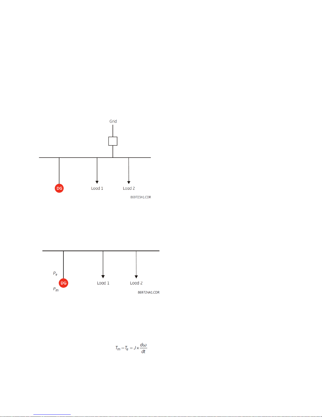
Figure 2 shows a typical Microgrid where DG represents a Diesel Generator.
Figure 2 Typical microgrid
Islanded Power System Operation
Within any power system, the generated power must match the demand. The loading in the system is variable.
Consider the single-generator power system shown in Figure 3.
Figure 3 Single-generator power system
and Pm result from multiplying the torque with the angular velocity (speed).
P
e
Where:
is the electrical power
P
e
is the mechanical power
P
m
The basic torque balance equation for the generator is:
Eq. 1
9
Page 10
DMC490 Microgrid Controller Software Configuration Guide
Where:
T
is the mechanical torque provided by the prime mover
m
is the electrical torque exerted by the loading of the power system
T
e
J is the inertia constant of the machine, and
ω is the rotational speed.
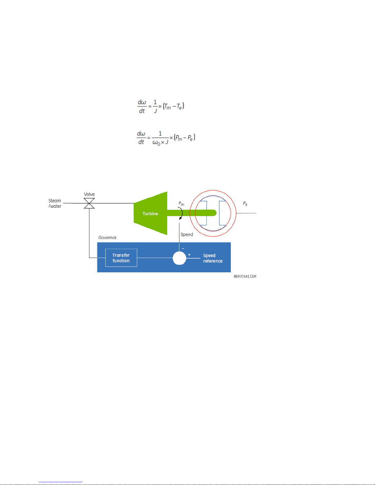
Solving for dω/dt, the result is:
Eq. 2
Multiplying by the top and bottom of this equation by rated speed, ω0, the result is:
Eq. 3
Speed is constant (dω/dt = 0) whenever mechanical power matches electrical power. This fact allows us to
control a generator to supply the required load by regulating the speed of the generator at a fixed value. This
method is known as isochronous control and is shown in Figure 4.
Figure 4 Isochronous control
Assume that electrical and mechanical power are initially equal and speed is equal to the reference speed.
When the loading of the system increases, then P
becomes greater than Pm. As seen in the previous equation,
e
the machine speed drops. The governor takes a measurement of machine speed and compares it with a
reference speed (nominal speed). The difference is an error signal that is applied to a transfer function (typically
a proportional/integral regulator). The output of the governor drives an actuator (for instance a valve in the
case of a steam turbine). This acts to increase the flow of steam to the turbine, increasing the mechanical
power to balance the electrical power.
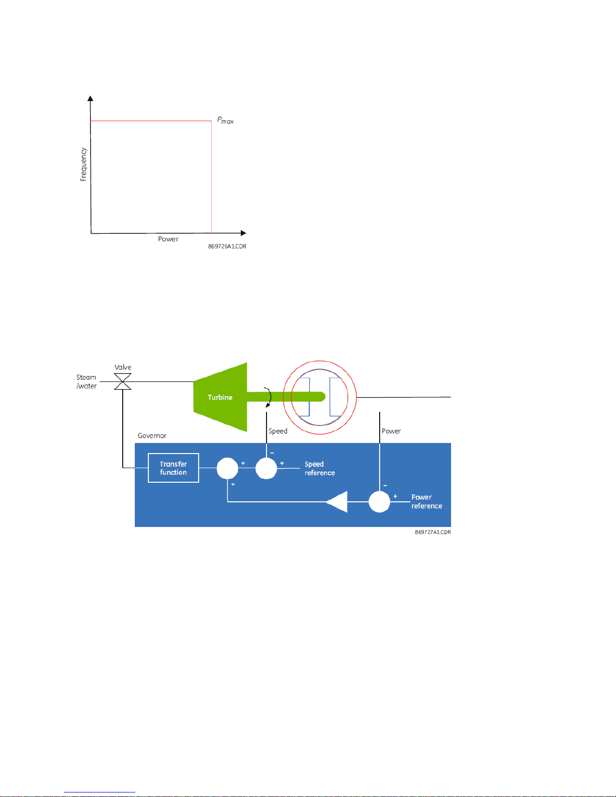
The operating characteristic of an isochronous generator is shown in the plot of frequency (proportional to
mechanical speed) and power; see Figure 5.
10
Page 11
DMC490 Overview
Figure 5 Isochronous operating characteristic
An isochronous machine maintains a constant frequency for any value of power up to its maximum rating.
Having more than one generator operating in isochronous control creates a challenge. Measurement error
results in each machine having a slightly different idea of the actual system frequency, and each machine tries
to bring this value to the nominal frequency. To resolve this potential conflict, one machine is typically operated
in isochronous mode and the remaining generators are operated in droop control, resulting with the machine
receiving an additional power signal that it compares to a power reference.
Figure 6 Droop control used for two or more sources of power
At nominal frequency, the level of power output is determined by the power reference command because the
speed error signal is zero. When there is a drop in frequency, the generator increases output power according
to its droop setting. For example, a generator with a droop setting of 5% produces a 100% change in output
power for a 5% change in frequency.
Taken together the power and speed signals produce a sloped operating characteristic as shown in Figure 7.
11
Page 12
DMC490 Microgrid Controller Software Configuration Guide
Figure 7 Droop control operating characteristic
In grid-connected microgrids, the grid compensates for any imbalance between load and generation in the
microgrid, behaving like an isochronous machine for the microgrid. However, for islanded microgrids, there is a
need for an isochronous machine to maintain load-generation balance, and stabilize the frequency around the
nominal value in response to instantaneous load and renewable generation variations above or below the
forecasted values. Such an isochronous machine provides reserve margins in both positive and negative
directions to address the deficit or surplus of power, respectively. These margins are defined as a percent of the
total load in the microgrid.
Isochronous/non-isochronous operation of a generator impacts the behavior of the MGC in the process of
optimally dispatching the generation/storage devices in the microgrid. Thus, generating power of a
dispatchable generator (genset) operating in non-isochronous mode can pick any value between its lower and
upper bounds; however, for an isochronous dispatchable genset, lower and upper bounds of generating power
need to be changed in the optimization problem solved by the MGC so that the reserve margins are respected.
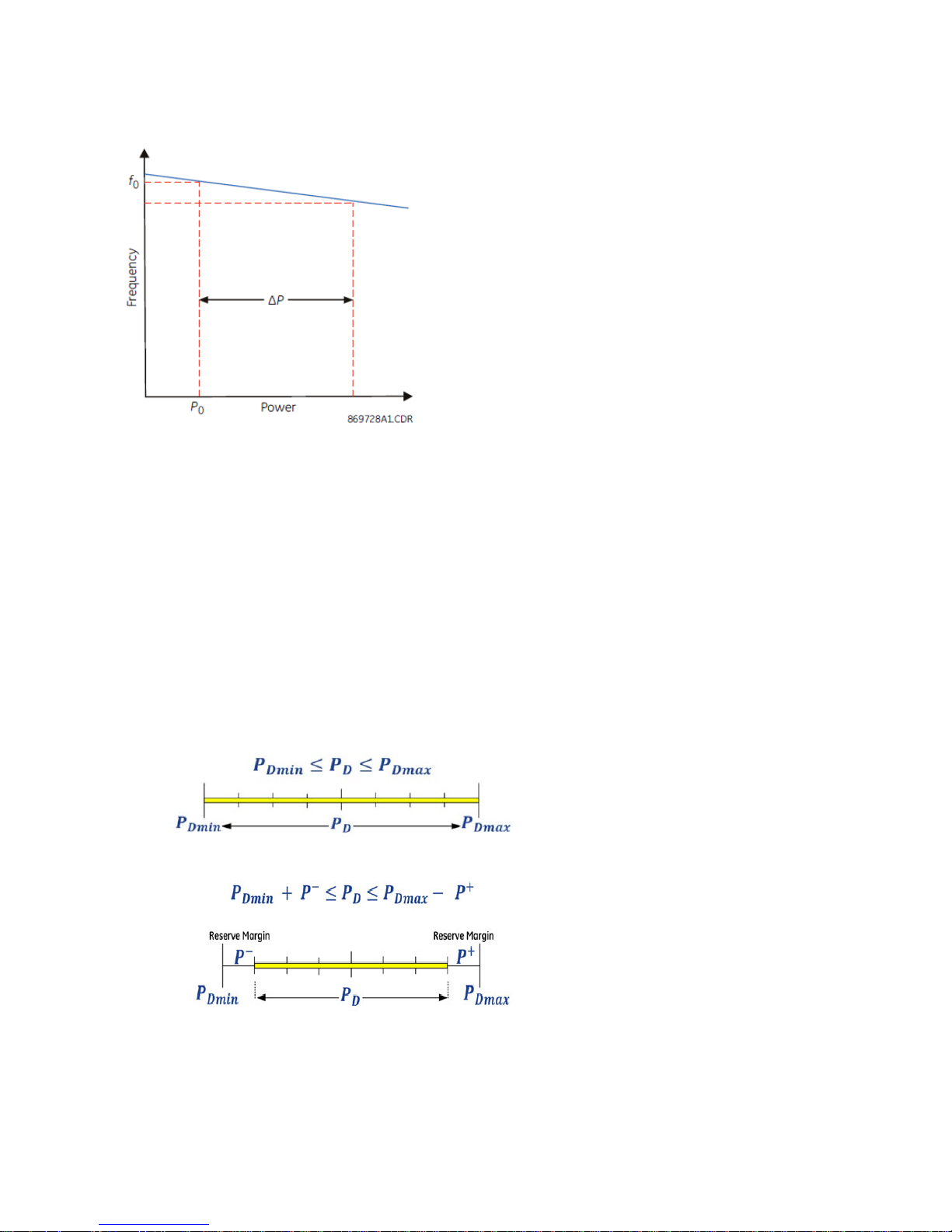
These concepts are demonstrated in Figure 8 and Figure 9, where the highlighted regions specify the intervals
that the generating power (P
) is allowed to change. PD
D
and PD
min
represent the lower and upper bounds of
max
dispatchable generating power.
Figure 8 Demonstration of non-isochronous operation of a dispatchable generator
Figure 9 Demonstration of the isochronous operation of a dispatchable generator
A diesel or a CHP unit can usually operate in isochronous mode due to the non-variable nature of their fuel
source, while highly-intermittent renewable power sources such as wind or solar cannot fulfill the requirements
of an isochronous machine. However, the MGC supports the isochronous operation of renewable power
generation units that are relatively less intermittent, such as run-of-the-river hydro units with reservoirs. In
order to support such a feature, a parameter entitled Renewable Capability is defined in the setup program.
12
Page 13

DMC490 Overview
This is a parameter between 0 and 1, multiplied by the upper bound of renewable power generation unit, and
decided by the operator based on meteorological observation data.
Optimal Dispatch
The primary function of the MGC is optimal dispatch, which is the process of allocating the required load
demand among the available resources such that the cost of operation is minimized. The MGC minimizes cost
of electricity and/or heat in a microgrid, for example daily, and the prediction horizon can extend up to 48
hours.
Within a microgrid, resources include conventional generators and storage devices. The cost of operation is
typically defined by fuel cost but can include maintenance and other costs.
An optimal dispatch algorithm is used to minimize the total operational cost of the microgrid. This cost is the
sum of the fuel cost required to run the non-renewable generators, cost of electricity, which needs to be
bought from a grid when one exists, and the operational cost of renewable and storage devices. Other factors
include maintenance, start-up/shut-down costs, cost/revenue components associated with
importing/exporting power to the grid, minimum energy/power requirements for various generation assets and
minimum up/down times for some of the assets. The power bought from the grid plus the power generated
internally must equal the total load and the power exported to the grid at any instant of time. The algorithm
does not treat loads as dispatchable except to avoid situations of grid instability associated with imbalance
between supply and demand. In other words, the microgrid always supplies enough power to satisfy its loads
provided that this is physically possible given the power limits on the generators.
The optimal dispatch algorithm uses a technique known as model predictive control. It makes use of historical
data as follows: daily, weekly, and annual load profiles; hydro, wind, and solar forecasts; and fuel or electricity
market pricing information (when a bulk grid connection exists). Given this information, the algorithm
determines the cost of operation for a fixed period in the future, typically 24 hours. It then solves the
optimization problem with the objective to minimize the total costs and to determine the required control
actions. These control actions include selecting the best machines to be operated at any given time, by issuing
start/stop commands and sending proper isochronous or non-isochronous commands to dispatchable or
renewable power generation units. It determines when energy is stored and when it is supplied to the system.
Finally, it determines the best power reference point for each droop (non-isochronous) machine and for each
storage device. Figure 10 shows data flow between the MGC and the different component devices within the
microgrid.
13
Page 14
DMC490 Microgrid Controller Software Configuration Guide
DMC490
Microgrid Controller
System
Loads
Renewable
generators
Power generated
Online status
Availability
Power consumed
Online status
Dispatchable
generators
Power generated
Online status
Availability
Storage
devices
Start/stop
Input preferences
Output preferences
Power generated
Power consumed
State of charge
Online status
Availability
Setup tool
Operational
parameters (settings)
Start/stop
Isochronous/droop
Output preferences
Figure 10 Data flow for a system with dispatchables, renewables, and storage
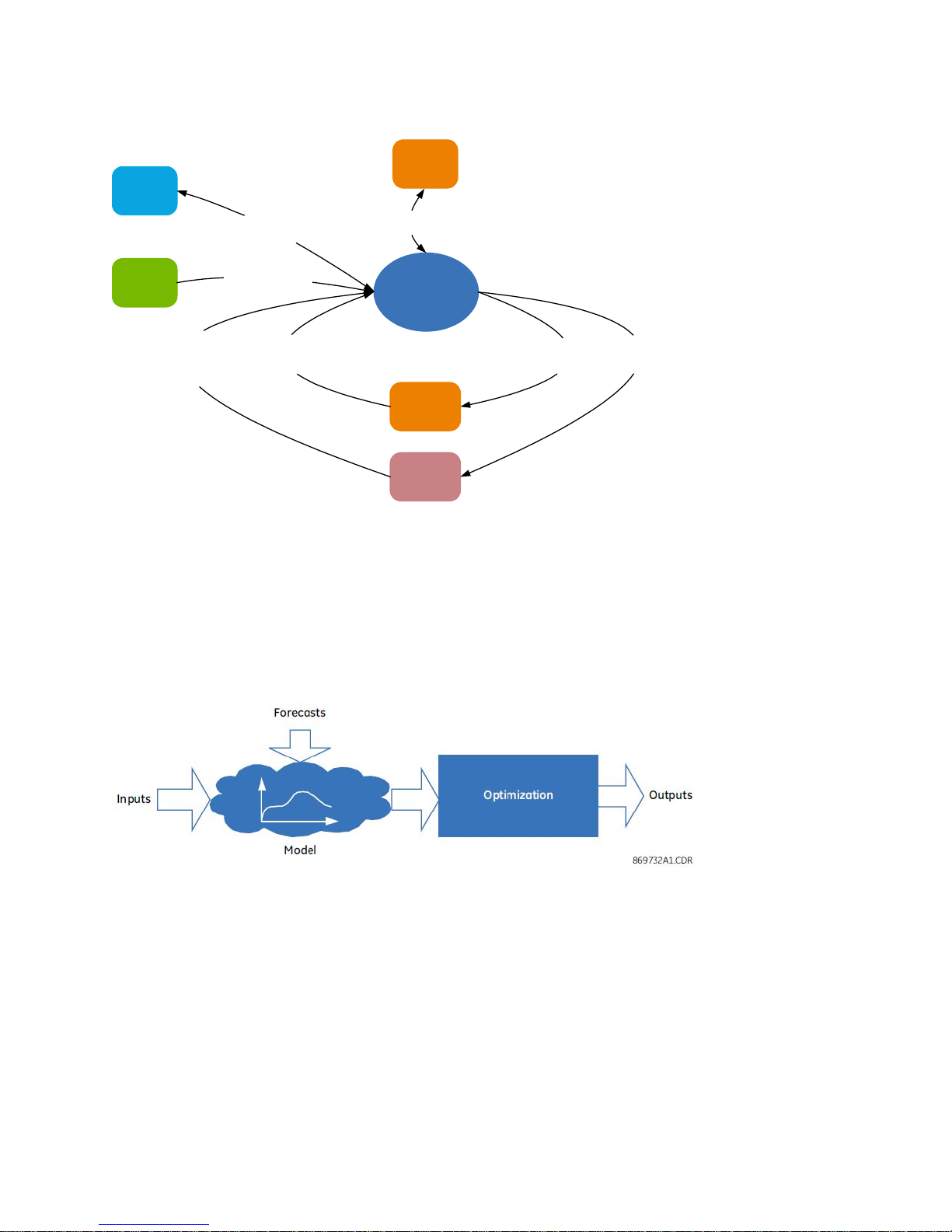
Model Predictive Control
Model predictive control (MPC) is used for optimal dispatch in the microgrid. In this method, a model of the
process to be controlled is used to evaluate the behavior of process outputs in response to control inputs. The
model response is evaluated for a finite period extending into the future, known as a prediction horizon. The
outputs are optimized over this period in order to arrive at the ideal values of outputs to be applied at the
current time.
Figure 11 Model predictive control
Applied to the dispatch challenge, inputs represent internal physical states of the process such as
offline/online, availability, isochronous operation, storage state of charge, and metered power of the devices.
Generators and storage devices are modeled by their power ratings and efficiency curves. Forecasts model the
loading of the power system, the contribution of renewable sources, and the price of grid power (if one exists).
Finally, outputs take the form of start/stop commands and power reference commands applied to generators
and storage devices.
Generation must match load in a stable power system. Dispatchable generation including the storage equals
the total load minus the total power supplied by renewable sources. These resources are assumed to have
local controllers that are designed to maximize the use of available renewable energy.
The problem to be solved by the MGC is a multi-interval optimization problem. As shown in Figure 12, an
assumed prediction horizon of 24 hours is divided into multiple time steps/intervals, such as 120 twelve-minute
or 240 six-minute time intervals.
14
Page 15

DMC490 Overview
Figure 12 Prediction horizon
Different routines within the optimization framework are formulated and solved at each time step (for example,
12 minutes) over the prediction horizon (24 hours) based on load, renewable resources, and price forecasts. In
this framework, a variety of operational considerations are factored in. These include and are not limited to the
support of a hydro unit in isochronous mode, minimum up/down times required for storage charging,
interaction with the grid, and support of manual-start dispatchable generators.
The objective function of the optimization problem can, in general, include the following terms:
• Fuel/operation costs of all power generation devices in the microgrid
• Cost/incentive terms for storage device charging/discharging. These are more subjectively
determined, being driven by the requirement to prevent simultaneous charging and discharging and
the need to limit storage cycling.
• Penalty terms mainly related to those generation/storage devices allowed to have their limits on
minimum powers violated (that is, having soft constraints)
• Power importing/exporting costs/revenues when the microgrid is grid-connected
Also, the constraints of the optimization problem capture the following limitations for both electrical and
thermal systems:
• Minimum and maximum values of generated power with the consideration of their isochronous or
non-isochronous operation, and the microgrid reserve margin requirements
• Limits on importing/exporting powers considering the microgrid reserve power requirements (for grid-
connected microgrids)
• Power balance in the microgrid considering the contribution of power generation/storage devices,
load, and any grid
• Minimum, maximum, and initial values of storage devices state of charge
• Limits on storage input and output powers
• The energy balance equation of storage devices representing the storage state of charge in each time
step based on its value in the previous time step as well as charging and discharging powers with the
consideration of the related efficiencies and standby losses
When the prediction horizon is long enough, the algorithm can determine when to charge storage, because it
can anticipate times when the loads are large and when the stored power can be utilized. The optimal dispatch
algorithm implemented within the microgrid controller can be configured for up to 32 resources. Assuming a
worst-case scenario where all resources are committed, the optimization problem can have on the order of
20,000 variables and 40,000 constraints.
Incorporation of CHP Plants
Combined heat and power (CHP) is the generation of electricity and heat in a single process. Inclusion of CHP
plants in the microgrid significantly increases the overall efficiency of the system by using the hot exhaust
gases from the gas turbine to heat water. Recovered heat can also be used for district heating or covering the
heat demand requirement of the system. The incorporation of CHP plants introduces another energy source
(natural gas) and another energy carrier (heat) into the system.
A CHP plant can be modeled by constant conversion ratios. The conversion ratios indicate efficiency. For
example, a gas-to-electricity conversion ratio of 0.35 means that 35% of the energy content of natural gas is
converted to electricity and the remainder is in the form of heat. Two dimensionless conversion ratios for gasto-electricity (rge) and gas-to-heat (rgh) are defined as shown in the following figure. Typical values of rge and
rgh are 0.35 and 0.45, respectively, considering a 20% parasitic loss.
15
Page 16

DMC490 Microgrid Controller Software Configuration Guide
related configuration.
Figure 13 Representation of the co-generator model
Note: Different energy source and carriers, meaning natural gas, electricity, and heat, are involved, and that
they are all represented in terms of a common unit (kW). Note too that P
independently controlled. Also, fuel consumption rate of a CHP unit reflected in the objective function is
assumed to be an affine function of its generated electric power; this is similar to all dispatchable units
in the microgrid.
Similar to dispatchable generators, CHP units can also operate in isochronous mode to cover the electric
system reserve requirements.
CHPe
and P
CHPh
are not
Microgrid Controller Setup
The Microgrid Controller is set up for microgrid operation and control from the DMC490 HMI.
» To connect and configure a microgrid, perform the following tasks:
1. Set up communication between Assets controller or Asset of the Microgrid to the DMC490 using Data
Collection Application; see Chapter 17 - Configure IED/Device Blocks (Clients) of the SWM0066 D400
Software Configuration Guide.
2. Follow the configuration procedure provided in Chapter 2 – DMC490 Configuration of this manual.
Using SGConfig to Configure the DMC490
SGConfig (v9.0 or later) can be used to configure LogicLinx for a DMC490.
The following SGConfig features are not supported and will fail if you attempt to use them
to configure a DMC490:
• Offline editor
• Bulk editing
• Import/export
If you attempt to use the offline editor and commit the changes, you will lose the MGC-
16
Page 17

DMC490 Configuration
Boilers
8
CHPs
8
Dispatchables (auto-start)
16
Grids
1
Heat Loads
16
Loads
16
Renewables
16
Storage
16
DMC490 Configuration Chapter 2 -
You specify the number of dispatchable generators, loads, boilers for heat, renewable resources, and so on in
the DMC490 Configuration Tools.
Up to 32 resources can be connected in the microgrid, with maximum per device type as follows.
Maximum configuration by device type
Resource Maximum number (up to total of 32)
DMC490 Operation Modes
The MGC optimization function has different modes of operations, which determine whether optimization is on
or off.
Modes of Operation
The modes of operation are:
• Legacy (Off) — Off — In this mode, no optimization takes place and no communication occurs with the
resources and assets in the microgrid. When a user selects this mode, the microgrid continues to operate
using the last configured values. For example, when a diesel generator is on, and the user activates Legacy
(Off) mode, the diesel generator continues to operate.
The Analog Value code for this mode is 0.
• Auto — On — In this mode, Optimization occurs and the optimal solution is communicated to the resources
and assets.
The analog value code for this mode is 1.
• Advisory — On — In this mode, Optimization occurs, but the optimal solution is not communicated to the
resources and assets. When there is a problem in the microgrid, the unit automatically switches to this
mode to prevent commands from being sent to devices. To fix this issue, inspect the system, including
generation and storage devices, local controllers, and communication links.
The analog value code for this mode is 2.
Note:: Delay is associated in the Process of transitioning between the modes. The mode cannot be abruptly
changed from off to Auto; it first switches to Advisory mode, and if the optimization problem is feasible,
and an optimal solution is found, the operation mode changes from Advisory to Auto at the end of the
problem-solving phase. This transition is indicated by "Running Optimal Dispatch" on the main HMI
pane.
17
Page 18

DMC490 Microgrid Controller Software Configuration Guide
View and Switch Modes
» To view the state of Optimizer Operation Mode:
1. Navigate to the MGC application Point details page on the HMI:
Point Summary > Applications > Microgrid Controller> Analog Input
2. Use the Analog Input pseudo point MGC Current state from the MGC point summary page.
» To switch between different Optimizer Operation modes:
1. Navigate to the MGC application Point details page on the HMI:
Point Summary > Applications > Microgrid Controller> Analog Output
2. From the Analog Output tab, access pseudo point MGC Change Current state.
3. Choose a desired mode based on the Analog codes given for each mode.
» To view the time remaining until the next cycle of Optimization is executed:
1. Navigate to the MGC application Point details page on the HMI:
Point Summary > Applications > Microgrid Controller> Analog Input
2. From the Analog Output, access pseudo point MGC Change Current state.
3. See the status for the Time to Next Advice point.
Configuration Overview
Microgrid Assets
» To configure and map microgrid assets:
1. Click the Configuration Power Bar button and select the MGC tab.
Result: The Electrics pane appears.
2. Select: Electrics (Electrical Assets) tab or the Thermal (Thermal Assets) tab.
3. If Electrics or Thermal is selected, click + to add an asset.
Result: The Create Asset window appears.
4. Select the Asset type:
• Electrical Assets
o Renewable Asset
o Dispatchable Asset
o Storage Asset
o Load Asset
o Grid Asset
• Thermal Assets
o Thermal CHP Asset
o Boiler Asset
o Heat Load Asset
18
Page 19

DMC490 Configuration
Result: The settings pane appears on the right-hand side; for example, Dispatchable Asset1.
5. Configure the Electrical Assets and Thermal Assets Point settings. Refer to the Configure Electrical Assets
section on page 20 for more details.
6. Add digital/analog inputs and digital/analog outputs for the assets.
7. Set the time periods for the forecasts: System (Settings > Economic Dispatch setup.
8. Configure annunciator alarms (Configuration > Alarm tab > Alarm Points tab) that are viewed on the
Active Alarms page.
9. Set the operating mode of the MGC assets (that is, Renewable assets, Dispatchable Assets, and Thermal
CHP Assets
10. Configure forecast settings for optimization.
11. Map the Electrical Assets and Thermal Assets status points to the Datalogger (click: Data Logger
powerbar button) so that you can analyze decisions made by the Optimizer over the logging period.
12. Repeat steps 1 to 11 for each microgrid asset.
System Settings
» To configure microgrid system settings:
1. Click the Configuration Power Bar button and select the MGC tab.
Result: The Electrics pane appears.
2. Select the Settings (System Settings) tab.
3. Select the System Settings group:
• System Settings
• Economic Dispatch
• Command Scheduler
o Dispatchable Units
o Storage Units
Result: The settings pane appears on the right-hand side; for example, System Settings.
19
Page 20

DMC490 Microgrid Controller Software Configuration Guide
Setting
Description
Range
Default
Enabled
Rated Power
(kW)
Specify the maximum power generation capacity in kW
depending on the availability of the renewable resource.
0 to 1,000,000
kW
Operating
Specify the operating cost of the equipment in dollars per
$0 to
$0
Isochronous
Mode3
Configure Electrical Assets
» To configure Electrical Settings:
Navigate to Configuration > MGC > Electrics >
• Renewable asset
• Dispatchable asset
• Storage asset
• Load asset
• Grid asset
Renewable Asset
Configure each renewable resource with settings such as power generating capacity and operating cost of a
photovoltaic array.
Renewable resources of the same type that are co-located are considered one device.
Point Settings
Asset ID Unique asset ID assigned by the DMC490 MGC.
Name Specify the name of the asset.
Enabled
Cost ($/kWh)
Isochronous
Operation
Mode1
Operation
Mode2
Isochronous
Operation
Specify if the asset is to be included in the microgrid
optimization calculations.
kWh. Include operations, maintenance, and (any) fuel costs.
The cost is in dollars; for other currencies simply enter that
value and be consistent in all fields involving the currency.
Specify if isochronous or droop (non-isoch) mode is to be
used for the renewable resources in each of the microgrid
operation modes.
The numbers 1 to 4 for this setting refer to operation modes
for the microgrid. Depending on the type of isochronous
machine and how the reserve margins are provided, four
different operation modes can be considered for the
microgrid. The following modes are some examples that can
be used:
4 to 20
characters
Disabled
$1,000,000
Isoch
Droop
Renewable
Asset_
Enabled
250 kW
Droop
20
Page 21

DMC490 Configuration
Isochronous
• Dispatchable/CHP isochronous load sharing
Setting
Description
Range
Default
Asset ID
Unique asset ID assigned by the DMC490 MGC.
Name
Specify the name of the asset.
4 to 20
Dispatch
Operation
Mode4
• Hydro in isochronous
• Single dispatchable/CHP in isochronous
• Grid in isochronous
For example, assume in a particular microgrid, one big hydro
generator (such as a run-of-the-rive hydro unit with a
reservoir) can operate in isochronous mode.
This corresponds to Operation Mode 2; however, any of the
four operation modes can be assigned to a single hydro unit
in isochronous. If the operator follows the suggested
operation-mode assignment (that is, Operation Mode 2 is
hydro in isochronous) and Hydro 1 is supposed to be the
isochronous machine, the following are set for this machine:
• Operation Mode 1 = Droop
• Operation Mode 2 = Isoch
• Operation Mode 3 = Droop
• Operation Mode 4 = Droop
In this manner, if you select the second mode to be the active
mode for the microgrid, then Hydro 1 can run in isochronous
mode by receiving the isochronous command from the
DMC490 MGC.
For the other microgrid operation modes, Hydro 1 is in nonisochronous mode (as set by zero values).
Status Points
The following field mappings apply to the status/control and read-only inputs that are to be mapped to the
Microgrid controller > Renewable Asset configuration page:
• Online: This field indicates if the renewable resource is online or offline.
• Isoc Mode: This field indicates if the resource is in droop or isochronous mode.
• Net Meter Power: This field indicates the power generation values (in kW) read from different
renewable generators in the system.
• Operation mode: This is an Analog output which refers to the current microgrid operation mode of the
asset (as explained in section System Settings on page 19, see the Active Mode setting).
• Watchdog: This is a Digital Output command used to inform the asset that the MGC controller is
active. A Digital Output command is sent on this point with the value toggling between 0 and 1 every
10 seconds.
Dispatchable Asset
Configure each dispatchable resource with settings such as operating capacity, operating cost, and minimum
operating period of an auto startup diesel generator.
Point Settings
characters
able
Asset_
21
Page 22

DMC490 Microgrid Controller Software Configuration Guide
Specify if the asset is to be included in the microgrid optimization
Enabled
Rated Power
Specify the maximum power generation capacity of the
0 to
250 kW
Start Cost ($)
Specify the cost to power up the resource. Include the costs that
$0 to
$10
Specify the cost to power down the resource. The cost is in dollars;
$0 to
Fuel Cost ($/L)
Specify the cost of fuel that operates the dispatchable generator, in
$0 to $100
$1
Enabled
(kW)
Minimum
Power (kW)
Efficiency
Maximum
(kWh/kg)
Efficiency
Minimum
(kWh/kg)
calculations.
dispatchable resource in kW.
Specify the preferred minimum power, in kW. For example, some
generators need to be operated at a minimum of 30 percent of their
rated power, expressed in kW.
Specify the efficiency at maximum generator power, in kWh per kg
of fuel consumed. Calculate the number using the related curves for
your generator. If the dispatchable efficiency at maximum power is
available in terms of percent, this setting can simply be determined
by multiplying the percent value with the higher heating value or
energy content of the input fuel in terms of kWh/kg. Higher heating
values for different fuel sources can be found in the related
handbooks or the Internet.
Specify the efficiency at minimum generator power, in kWh per kg
of fuel consumed. Generators are usually less efficient when
operating at low loads. Calculate the number using the related
curves for your generator. If the dispatchable efficiency at minimum
power is available in terms of percent, this setting can simply be
determined by multiplying the percent value with the higher heating
value or energy content of the input fuel in terms of kWh/kg. Higher
heating values for different fuel sources can be found in the related
handbooks or the Internet.
Disabled
1,000,000
kW
0 to
1,000,000
kW
0 to 1,000
kWh/kg
0 to 1,000
kWh/kg
Enabled
50 kW
0.75
kWh/kg
0.55
kWh/kg
Stop Cost ($)
Fuel Density
(kg/L)
you think are important based on your experience with the
microgrid. The cost is in dollars; for other currencies simply enter
that value and be consistent in all fields involving the currency.
for other currencies simply enter that value and be consistent in all
fields involving the currency.
dollars per liter. For example, enter the price for a liter of diesel fuel
or gasoline. The volume of gaseous fuels is usually expressed in
terms of Normal cubic meter (Nm3). Therefore, Fuel Cost of
dispatchable generation resources running on gaseous fuels can
also be expressed in terms of dollars per Nm3; however, in this
case, Fuel Density also needs to be in terms of kg per Nm3. The cost
is in dollars; for other currencies simply enter that value and be
consistent in all fields involving the currency.
Specify the specific gravity of fuel in kg per liter. Values differ based
on the fuel type, such as natural gas and diesel. Use reference
books or the Internet to determine this value. Examples are 0.832
kg/L for diesel, 0.745 kg/L for ethanol-free gasoline, 0.71 to 0.77
kg/L for gasoline, and 0.41 to 0.5 kg/L for liquefied natural gas (LNG).
Fuel Density can also be expressed in terms of kg/Nm3, which is
common for gaseous is case, Fuel Cost also needs to be expressed
in terms of $/Nm3. The unit of volume in both Fuel Cost and Fuel
Density settings need to be the same.
$1,000,000
$1,000,000
0 to 1,000
kg/L
$10
0.85 kg/L
22
Page 23

DMC490 Configuration
Constraint
Soft constraint means that the generator is allowed to violate its
Minimum
Use this setting in conjunction with Constraint Mode. This setting
and be consistent in all fields involving the currency.
0 to 1,000
Isochronous
Specify if isochronous or droop (non-isoch) mode is to be used for
Isochronous
Isochronous
Mode
Power Penalty
($/kWh)
Operation
Mode1
Operation
Mode2
Isochronous
Operation
Mode3
Operation
Mode4
minimum power generation level but at the cost of a penalty in the
objective function. Having the possibility of going below the
minimum power (soft constraint) can positively affect the feasibility
of the microgrid optimization problem.
Hard constraint means that the generator is not allowed to go
below its minimum power generation level.
Use this setting in conjunction with Minimum Power Penalty.
puts a numerical value on the minimum power violation. When the
violation from minimum power is critical, set a high value here.
The cost is in dollars; for other currencies simply enter that value
the renewable resources in each of the microgrid operation modes.
Operation mode numbers 1 to 4 refer to operation modes for the
microgrid. Depending on the type of isochronous machine and how
the reserve margins are provided, four different operation modes
can be considered for the microgrid.
For example the following mode numbers can be used:
1. Dispatchable/CHP isochronous load sharing
2. Hydro in isochronous
3. Single dispatchable/CHP in isochronous
4. Grid in isochronous
Assume in a particular microgrid, one big hydro generator
(such as a run-of-the-rive hydro unit with a reservoir) can
operate in isochronous mode. This corresponds to Operation
Mode 2; however, any of the four operation modes can be
assigned to a single hydro unit in isochronous. If the operator
follows the suggested operation-mode assignment (that is,
Operation Mode 2 is hydro in isochronous) and Hydro 1 is
supposed to be the isochronous machine, the following are set
for this machine:
• Operation Mode 1 = Droop
• Operation Mode 2 = Isoch
• Operation Mode 3 = Droop
• Operation Mode 4 = Droop
In this manner, if you select the second mode to be the active
mode for the microgrid, then Hydro 1 can run in isochronous
mode by receiving the isochronous command from DMC490.
For the other microgrid operation modes, Hydro 1 is in nonisochronous mode (as set by zero values).
Hard
Soft
$/kWh
Isoch
Droop
Hard
0 $/kWh
Droop
Status Points
The following field mappings apply to the status and read only inputs that are to be mapped to the Microgrid
controller > Dispatchable Asset configuration page:
• Online: This field indicates if the resource is online or offline. It is not necessarily the same as being
available for use in the MGC optimization calculations.
• Input Isoch Mode: This field indicates if the resource is to be in droop or isochronous mode. There is an
input and output isoch mode. The input isoch mode is advice produced by the optimizer and issued to
the dispatchable asset. The output isoch mode is the actual operating mode of the dispatchable asset.
23
Page 24

DMC490 Microgrid Controller Software Configuration Guide
Setting
Description
Range
Default
Asset ID
Unique asset ID assigned by the DMC490 MGC.
4 to 20
characters
Storage
Asset_
Input Enabled
This setting indicates if the storage input/charging is set to be
Disabled
Enabled
Assuming that the dispatchable resource follows the advice of the optimizer, the modes are usually
the same.
• Availability: Availability is declared by the generator. This field indicates if the generator can be
controlled by the MGC and included in the optimization problem solved by the MGC. An online
generator is not necessarily an available generator. The availability signal is built by the generator’s
local controller based on some parameters and is read by the MGC.
• Net Meter Power: This field indicates the power generation values in kW read from different
dispatchable generators in the system.
The following field mappings apply to the AO/DO control points that are to be mapped to the Microgrid
controller > Dispatchable Asset configuration page:
• Start: Start/stop is a command. When the MGC sends the start command, the generator comes online
after some time.
• Output Isoch Mode: This field indicates if the resource is in droop or isochronous mode.
For isochronous mode, there is an input and output isoch mode:
o The input isoch mode is advice produced by the optimizer and issued to the dispatchable
asset.
o The output isoch mode is the actual operating mode of the dispatchable asset.
Assuming that the dispatchable resource follows the advice of the optimizer, the modes are usually
the same.
• Power Ref: This field refers to the power reference points of dispatchable generators, in kW. Their
values are computed by the MGC dispatch algorithm.
• Operation mode: This is an Analog output which refers to the current microgrid operation mode of the
asset (as explained in section System Settings on page 19, see the Active Mode setting).
• Watchdog: This is a Digital Output command used to inform the asset that the MGC controller is
active. A Digital Output command is sent on this point with the value toggling between 0 and 1 every
10 seconds.
Storage Asset
Configure each electrical storage installation with settings such as capacity and cost.
Storage devices of the same type that are co-located are considered one storage device.
Point Settings
Name Specify the name of the asset.
included in the microgrid optimization calculations by the
DMC490. When storage input is offline and the optimal
dispatch result indicates storage input usage above the
minimum storage input for equal to or longer than the
Charging Minimum Up Time, then the storage input is started.
For hydrogen storage, which is interpreted as the combination
of electrolyzer, high-pressure storage cylinders, and fuel cell,
enabling the input translates to enabling the electrolyzer.
Enabled
24
Page 25

DMC490 Configuration
This setting indicates if the storage output/discharge is set to
Storage Type
Specify if the storage is batteries or a hydrogen-based system,
Hydrogen
Battery
Minimum
Charging power for a storage device cannot be below a
0 to 1,000,000
efficiency of the storage cylinders is close to unity.)
Discharging
This setting describes how efficient the stored energy is
0% to 100%
55%
Output Enabled
Maximum
Discharging
Power (kW)
Minimum
Discharging
Power (kW)
Maximum
Charging Power
(kW)
Charging Power
(kW)
Charging
Efficiency (%)
be included in the microgrid optimization calculations by the
DMC490. For hydrogen storage, which is interpreted as the
combination of electrolyzer, high-pressure storage cylinders,
and fuel cell, enabling the output translates to enabling the
fuel cell.
such as the combination of electrolyzer, high-pressure storage
cylinders, and fuel cell.
Specify the maximum electrical power in kW that the storage
unit can discharge to the microgrid. For hydrogen storage,
which is interpreted as the combination of electrolyzer, highpressure storage cylinders, and fuel cell, this setting refers to
the rated power of a fuel cell.
Specify the minimum electrical power in kW that the storage
unit is to discharge to the microgrid. For hydrogen storage,
which is interpreted as the combination of electrolyzer, highpressure storage cylinders, and fuel cell, this setting refers to
the minimum fuel cell output power.
Specify the maximum input/charging power of the storage
unit in kW. For hydrogen storage, which is interpreted as the
combination of electrolyzer, high-pressure storage cylinders,
and fuel cell, this setting refers to the rated power of the
electrolyzer.
certain level, so Specify the minimum input/charging power of
the storage unit. This power level is related to the technology
and specifications of the storage device itself and it does not
depend on other dispatchable or renewable devices in the
system. For hydrogen storage, which is interpreted as the
combination of electrolyzer, high-pressure storage cylinders,
and fuel cell, this setting refers to the minimum input power of
the electrolyzer.
For example, for a 300 kW alkaline electrolyzer, this setting
can be in the range of 120 to 130 kW.
This setting describes how efficient the input or charging
power over time contributes in increasing the state of charge.
Charging efficiency depends on the input/charging power and
storage state of charge. However, it is assumed here to be a
fixed setting, which is acceptable in most applications. For
hydrogen storage, which is interpreted as the combination of
electrolyzer, high-pressure storage cylinders, and fuel cell, this
setting refers to the electrolyzer efficiency. (The charging
Disabled
Enabled
Enabled
Battery
0 to 1,000,000
50 kW
kW
0 to 1,000,000
25 kW
kW
0 to 1,000,000
50 kW
kW
25 kW
kW
0% to 100% 50%
Efficiency (%)
converted back to the microgrid. Discharging efficiency
depends on the output/discharging power and storage state
of charge. However, it is assumed here to be a fixed setting,
which is acceptable in most applications. For hydrogen
storage, which is interpreted as the combination of
electrolyzer, high-pressure storage cylinders, and fuel cell, this
setting refers to the fuel cell efficiency. (The discharging
efficiency of the storage cylinders is close to unity.)
25
Page 26

DMC490 Microgrid Controller Software Configuration Guide
State Of Charge
This setting is the maximum capacity of the storage device. It
0 to 1,000,000
State Of Charge
Specify the minimum level of storage state of charge, in kWh.
0 to 1,000,000
50 kWh
Lower
This setting is the upper boundary of the minimum acceptable
example one to five percent (that is, 0.01 to 0.05).
0 to 1 kW
0 kW
Lower
This setting is the lower boundary of the minimum acceptable
0 to 1 kW
0 kW
Maximum (kWh)
specifies the maximum level of storage state of charge (SOC),
in kWh.
300 kWh
kWh
Minimum (kWh)
Upper
Boundary Store
Device1 (kW)
Lower
Boundary Store
Device2 (kW)
Due to lifetime considerations, SOC cannot usually go below a
certain limit. This is referred to as maximum depth of
discharge (DOD). For example, for a 100kWh storage device
with 80% DOD, State Of Charge Minimum is set to 20 kWh.
Storage state of charge needs to be always above State Of
Charge Minimum and below State Of Charge Maximum.
However, a variety of practical complexities, such as storage
standby loss, delay in issuing the charging/discharging
commands, measurements errors, and startup or
environmental conditions, lead to the violation of these limits
and can render the real-time microgrid optimization problem
infeasible. Apart from the infeasibility of the optimization
problem, there is also a chance of an undesired phenomenon
occurring, which is frequent charging and discharging (cycling)
of storage devices. These undesired outcomes (that is,
infeasibility and cycling) are avoided in the DMC490 MGC by
having some pre and post processing units outside of the
optimization core to modify the commands issued by the
controller, such as storage stop/start, or to change some input
readings, such as SOC. This also requires defining some small
regions around State Of Charge Maximum and State Of
Charge Minimum.
Thus, two regions below State Of Charge Maximum, and two
regions on either side of State Of Charge Minimum are
defined as shown in the following figure. If SOC is located in
region E, no action is required; however, if SOC is within any of
four regions A to D, its measured value is appropriately
changed together with issuing some necessary
charging/discharging commands.
Upper Boundary Store Dev1 is the upper boundary of the
maximum acceptable charging level. Configure it to be within
a few percent of storage maximum capacity State Of Charge
Minimum, for example one to five percent (that is, 0.01 to
0.05).
Refer to Figure 14 for more details
This setting is the lower boundary of the maximum acceptable
charging level. Configure it to be within a few percent of
storage maximum capacity (State Of Charge Minimum), for
example one to five percent (that is, 0.01 to 0.05).
kWh
0 to 1 kW 0 kW
0 to 1 kW 0 kW
Boundary Store
Device1 (kW)
Boundary Store
Device2 (kW)
charging level. Configure it to be within a few percent of
storage minimum capacity (State Of Charge Minimum), for
charging level. Configure it to be within a few percent of
storage minimum capacity (State Of Charge Minimum), for
example one to five percent (that is, 0.01 to 0.05).
26
Page 27

DMC490 Configuration
Constraint
Soft constraint means that the storage device is allowed to
Charging Cost
This setting is the cost to charge the storage device in dollars
0 to 1,000
10 $/kWh
consistent in all fields involving the currency.
Mode
violate its minimum capacity State Of Charge Minimum but at
the cost of a penalty in the objective function. Having the
possibility of going below the minimum capacity (soft
constraint) can positively affect the feasibility of the microgrid
optimization problem but can also result in charge/discharge
cycling.
Hard constraint means that the storage is not allowed to go
below its minimum capacity (State Of Charge Minimum).
Use this setting in conjunction with State Of Charge Penalty,
State Of Charge Minimum Incentive and State Of Charge
Penalty.
($/kWh)
per kWh. Determine the cost based on your knowledge of the
microgrid or initial simulation studies. Including such costs
helps to prevent simultaneous charging and discharging and
helps to limit charge/discharge cycling. The cost is in dollars;
for other currencies simply enter that value and be consistent
in all fields involving the currency.
Discharging
Cost ($/kWh)
This setting is the cost to discharge power from the storage
unit in dollars per kWh. Determine the cost based on your
knowledge of the microgrid or initial simulation studies.
Including such costs helps to prevent simultaneous charging
and discharging and helps to limit charge/discharge cycling.
The cost is in dollars; for other currencies simply enter that
value and be consistent in all fields involving the currency.
Charging
Incentive
($/kWh)
This setting is the financial incentive to charge storage, in
dollars per kWh. In some jurisdictions, utilities are required to
store a percent of energy and incentives can be available for
such a program.
The incentive can be used to set this parameter for gridconnected microgrid configurations. In the absence of such an
incentive program, some simulation studies can be needed to
fine-tune this setting given the requirement to prevent
simultaneous charging and discharging and the need to limit
storage cycling.
The cost is in dollars; for other currencies simply enter that
value and be consistent in all fields involving the currency.
Discharging
Incentive
($/kWh)
This setting is the financial incentive to discharge storage, in
dollars per kWh. In the absence of incentive programs for gridconnected microgrids, some simulation studies can be needed
to fine-tune this setting given the requirement to prevent
simultaneous charging and discharging and the need to limit
storage cycling.
The cost is in dollars; for other currencies simply enter that
value and be consistent in all fields involving the currency.
State Of Charge
Penalty
($/kWh2)
This setting promotes discharging and lower values of SOC.
Both State Of Charge Penalty and State Of Charge Incentive
settings are provided to allow you more freedom to configure
the system based on your operational knowledge. The cost is
in dollars; for other currencies simply enter that value and be
Hard
Soft
$/kWh
0 to 1,000
$/kWh
0 to 1,000
$/kWh
0 to 1,000
$/kWh
0 to 1,000
$/kWh2
Hard
5 $/kWh
0 $/kWh
0 $/kWh
0 $/kWh2
27
Page 28

DMC490 Microgrid Controller Software Configuration Guide
State Of Charge
This incentive promotes more charging and higher values of
0 to 1,000
State Of Charge
The setting is the penalty when storage is allowed to violate its
0 to 1,000
0 $/kWh2
The DMC490 MGC supports input up-time, down-time, and
Charging
When the Hysteresis field is set to On, this is the minimum
0 to 720
0 minutes
Charging
When the Hysteresis field is set to On, this is the minimum off
at least this length of time.
0 to 720
0 minutes
Incentive
($/kWh2)
SOC. Both State Of Charge Penalty and State Of Charge
Incentive settings are provided to allow you more freedom to
configure the system based on your operational knowledge.
The cost is in dollars; for other currencies simply enter that
value and be consistent in all fields involving the currency.
0 $/kWh2
$/kWh2
Minimum
Penalty
($/kWh2)
Hysteresis
Minimum Up
Time (minutes)
Minimum Down
Time (minutes)
minimum level (that is, soft constraint is set for Constraint
Mode. The greater the violation from State Of Charge
Minimum, the greater the penalty cost in the objective
function.
The cost is in dollars; for other currencies simply enter that
value and be consistent in all fields involving the currency.
cycle-per-day hysteresis. When Hysteresis is On, a set of
appropriate parameters is in place to prevent excessive
switching and cycling. Support for hysteresis is required for
storage input to overcome high-frequency on/off cycling of
the electrolyzer because it lowers performance and decreases
the life of the device. The hysteresis mostly targets the
electrolyzer (hydrogen-based storage), but it is available for all
storage devices.
running time of the electrolyzer, in minutes. If the electrolyzer
is turned on, it runs for at least this length of time. When
storage input is offline and the optimal dispatch result
indicates storage input usage above the minimum storage
input (Minimum Charging Power) for equal to or longer than
the Charging Minimum Up Time, then the storage input is
started with the calculated setpoint.
time of the electrolyzer, in minutes. When the electrolyzer is
on and receives an off command, it turns off and stays off for
$/kWh2
On
Off
minutes
minutes
On
28
Page 29

DMC490 Configuration
Charging Limit
Yes means that the storage local controller provides the
Feedback
maximum value of discharging power for the DMC490 MGC to
read. No means that the value read by the DMC490 MGC is
disregarded.
For storage devices we have maximum charging power and
maximum discharging power; these are settings and fixed
values. However, for particular storage technologies, these
maximum powers are not fixed; they depend on the state of
charge (SOC). For example, we have a setting of 100 kW for
maximum discharging power but if SOC is below a certain limit
we cannot approach this maximum 100-kW limit. For these
particular storage devices, the maximum charging or
discharging powers are declared by their local controllers;
they have mathematical functions that calculate the
maximum power depending on the value of SOC; these values
are published so that an external device like the DMC490 can
read them.
Given this, the DMC490 has two related settings for storage
devices: Charging Limit Feedback and Discharging Limit
Feedback. For example, when the Charging Limit Feedback is
Yes, it means that the storage local controller provides the
maximum value of charging power (this is read by the
DMC490 and used in the optimization calculation). In this case,
the value read by the DMC490 is replaced with the maximum
value already set by the user. In other words, setting value for
maximum charging power is overwritten based on the value
provided by the storage local controller and read by the
DMC490.
When the Charging Limit Feedback is set to No, then the value
read by the DMC490 is disregarded.
False
True
False
29
Page 30

DMC490 Microgrid Controller Software Configuration Guide
Discharging
Yes means that the storage local controller provides the
Commitment1
Used by Unit
Commitment2
Used by Unit
Used by Unit
relatively high dissipation.
Limit Feedback
maximum value of discharging power for the DMC490 to read.
No means that the value read by the DMC490 is disregarded.
For storage devices we have maximum charging power and
maximum discharging power; these are settings and fixed
values. However, for particular storage technologies, these
maximum powers are not fixed; they depend on the state of
charge (SOC). For example, we have a setting of 100 kW for
maximum discharging power but if SOC is below a certain limit
we cannot approach this maximum 100-kW limit. For these
particular storage devices, the maximum charging or
discharging powers are declared by their local controllers;
they have mathematical functions that calculate the
maximum power depending on the value of SOC; these values
are published so that an external device like the DMC490 can
read them. Given this, the DMC490 has two related settings
for storage devices: Charging Limit Feedback and Discharging
Limit Feedback. For example, when the Charging Limit
Feedback is Yes, it means that the storage local controller
provides the maximum value of charging power (this is read
by the DMC490 and used in the optimization calculation). In
this case, the value read by the DMC490 is replaced with the
maximum value already set by the user. In other words,
setting value for maximum charging power is overwritten
based on the value provided by the storage local controller
and read by the DMC490. When the Charging Limit Feedback
is set to No, then the value read by the DMC490 is disregarded.
Used by Unit
Select yes to have storage contribution considered in the Unit
Commitment (UC) routine of the optimization problem.
The Unit Commitment problem is the task of determining a
combination of power generation units each with a certain
capacity and operation cost so as to minimize the total
Commitment3
Commitment4
operation costs while satisfying the electricity-demand
requirement of the microgrid in each time period.
The numbers 1 to 4 specify whether or not to consider the
contribution of storage devices in the Unit Commitment (UC)
routine in each of the four microgrid operation modes.
Charging
Dissipation
(kWh/h)
This setting represents energy loss from the storage device
over time. It specifies the rate of charge dissipation, or standby
loss of the storage, in kWh/h. You set this value based on your
knowledge of the storage technology used in the microgrid.
For example, some storage technologies, such as hydrogen,
have low standby losses while battery storage systems have
False
True
False
True
0 to 1,000
kWh/h
False
False
0 kWh/h
30
Page 31

DMC490 Configuration
Status Points
The following field mappings apply to the status and read only inputs that are to be mapped to the Microgrid
controller > Storage Asset configuration page:
• Input Online: This field indicates if the storage input is online or offline. For hydrogen storage, which is
interpreted as the combination of electrolyzer, high-pressure storage cylinders, and fuel cell, Input
Online represents the offline/online status of the electrolyzer. Being online is not necessarily the same
as being available for use in the MGC optimization calculations.
• Output Online: This field indicates if the storage output is online or offline. For hydrogen storage,
which is interpreted as the combination of electrolyzer, high-pressure storage cylinders, and fuel cell,
Output Online represents the offline/online status of the fuel cell. Being online is not necessarily the
same as being available for use in the MGC optimization calculations.
• Input Availability: Input availability is declared by the storage device. It indicates if the storage input
can be controlled by the MGC and included in the optimization problem solved by the MGC. The
availability signal is built into the storage local controller based on some parameters and is read by the
MGC. For hydrogen storage, which is interpreted as the combination of electrolyzer, high-pressure
storage cylinders, and fuel cell, Input Availability represents the availability of the electrolyzer. An
online storage resource is not necessarily an available storage resource.
• Output Availability: Output availability is declared by the storage device. It indicates if the storage
output can be controlled by the MGC and included in the optimization problem solved by the MGC. The
availability signal is built into the storage local controller based on some parameters and is read by the
MGC. For hydrogen storage, which is interpreted as the combination of electrolyzer, high-pressure
storage cylinders, and fuel cell, Output Availability represents the availability of the fuel cell. An online
storage resource is not necessarily an available storage resource.
• Net Meter Power In: This is the net metered input power, in kW. It indicates the input/charging power
value read from the storage device. For hydrogen storage, which is interpreted as the combination of
electrolyzer, high-pressure storage cylinders, and fuel cell, Net Meter Power In represents the
measured value of the electrolyzer input/charging power.
• Net Meter Power Out: This is the net metered output power, in kW. This field indicates the
output/discharging power value read from the storage device. For hydrogen storage, which is
interpreted as the combination of electrolyzer, high-pressure storage cylinders, and fuel cell, Net Meter
Power Out represents the measured value of the fuel cell output/discharging power.
• SOC: This field indicates storage state of charge, in kWh.
The following field mappings apply to the AO/DO control points that are to be mapped to the Microgrid
controller > Storage Asset configuration page:
• Input Start: This field represents the start command for storage charging. For hydrogen storage,
which is interpreted as the combination of electrolyzer, high-pressure storage cylinders, and fuel cell,
Input Start corresponds to the electrolyzer start command.
• Output Start: This field represents the start command for storage discharging. For hydrogen storage,
which is interpreted as the combination of electrolyzer, high-pressure storage cylinders, and fuel cell,
Output Start corresponds to the fuel cell start command.
• Power Ref In: This field reflects the reference input power of the storage device. It is the value decided
by the MGC for the storage charging power. For hydrogen storage, which is interpreted as the
combination of electrolyzer, high-pressure storage cylinders, and fuel cell, Power Ref In represents the
command for electrolyzer input/charging power.
• Power Ref Out: This field reflects the reference output power of the storage device. It is the value
decided by the MGC for the storage discharging power. For hydrogen storage, which is interpreted as
the combination of electrolyzer, high-pressure storage cylinders, and fuel cell, Power Ref Out
represents the command for fuel cell output/discharging power.
31
Page 32

DMC490 Microgrid Controller Software Configuration Guide
Setting
Description
Range
Default
Asset ID
Unique asset ID assigned by the DMC490 MGC.
Enabled
• Operation mode: This is an Analog output which refers to the current microgrid operation mode of the
asset (as explained in section System Settings on page 19, see the Active Mode setting).
• Input Watchdog: This is a Digital Output command used to inform the charge controller in the Storage
asset that the MGC controller is active. A Digital Output command is sent on this point with a value
toggling between 0 and 1 every 10 seconds.
• Output watchdog: This is a Digital Output command used to inform the discharge controller in the
Storage asset that the MGC controller is active. A Digital Output command is sent on this point with a
value toggling between 0 and 1 every 10 seconds.
Figure 14 Upper Boundary Store – State of Charge
Load Asset
Configure each load for the use of the electricity, such as which forecast to use.
Point Settings
Name Specify the name of the asset. 4 to 20 characters Load Asset_
Enabled
Status Points
The following field mappings apply to the status/control and read only inputs that are to be mapped to the
Microgrid controller > Load Asset configuration page:
• Online: This field indicates if the load is online or offline, meaning consuming electricity or not.
• Net Meter Power: This field indicates the values of demanding powers in kW read from different loads
in the system.
• Operation mode: This is an Analog output which refers to the current microgrid operation mode of the
asset (as described in section System Settings on page 19, see the Active Mode setting).
• Watchdog: This is a Digital Output command used to inform the asset that the MGC controller is
active. A Digital Output command is sent on this point with the value toggling between 0 and 1 every
10 seconds.
Specify if the asset is to be included in the microgrid
optimization calculations.
Disabled
Enabled
32
Page 33

DMC490 Configuration
Setting
Description
Range
Default
Export
Specify if exporting from the microgrid to the grid is enabled.
and Export Enabled to Disabled.
Disabled
Enabled
Minimum
Minimum amount of electricity to import from the grid to the
0 to 1,000,000
50 kW
Minimum
Minimum amount of electricity to export to the grid from the
0 to 1,000,000
10 kW
Grid Asset
Configure each grid, such as the amount of power to import.
Point Settings
Asset ID Unique asset ID assigned by the DMC490 MGC.
Name Specify the name of the asset.
Enabled
Import
Enabled
Specify if the asset is to be included in the microgrid optimization
calculations.
Specify if importing from the grid to the microgrid is enabled.
This setting takes the grid contribution into the microgrid
optimization calculations but only import power from the grid is
allowed. If both Import Enabled and Export Enabled are set to
Enabled, optimization calculations decide whether import power
from the grid or export power to the grid happens depending
upon the optimal contribution of generation/storage devices in
the microgrid.
For off-grid or autonomous microgrids, set both Import Enabled
and Export Enabled to Disabled.
4 to 20
characters
Disabled
Enabled
Disabled
Enabled
Grid
Asset_
Enabled
Enabled
Enabled
Maximum
Import
Power (kW)
Import
Power (kW)
Maximum
Export
Power (kW)
Export
Power (kW)
This setting takes the grid contribution into the microgrid
optimization calculations but only export power to the grid is
allowed. If both Import Enabled and Export Enabled are set to
Enabled, optimization calculations decide whether import power
from the grid or export power to the grid happens depending
upon the optimal contribution of generation/storage devices in
the microgrid.
For off-grid or autonomous microgrids, set both Import Enabled
Maximum amount of electricity to import from the grid to the
microgrid, in kW.
microgrid, in kW.
Maximum amount of electricity to export to the grid from the
microgrid, in kW.
microgrid, in kW.
Enabled
0 to 1,000,000
kW
kW
0 to 1,000,000
kW
kW
100,000
kW
100,000
kW
33
Page 34

DMC490 Microgrid Controller Software Configuration Guide
Power
While power that can be supplied by a grid is a continuous
0 to 1,000,000
Setting
Description
Range
Default
Asset ID
Unique asset ID assigned by the DMC490 MGC.
Asset_
Specify if the asset is to be included in the microgrid optimization
Enabled
10 kW
Resolution
(kW)
quantity, the DMC490 allows partitioning of the load requirement
into discrete values. That is, the DMC490 allows the grid to
supply a combination of a finite set of power values. This is
useful because the DMC490 typically has several power sources
in the microgrid with which to optimize, including any grid.
This setting is power in terms of kW. It is the resolution of the
discrete values for power grid supply.
The lower the number, the more flexibility provided for
optimization.
kW
Status Points
The following field mappings apply to the status/control and read only inputs that are to be mapped to the
Microgrid controller > Grid Asset configuration page:
• Online: This field indicates if the resource is online or offline. The status of being online can also
translate to having grid connection.
• Net Meter Power: This field indicates the import/export power value, in kW.
• Importing: This field indicates whether the grid is importing or exporting power.
• Operation mode: This is an Analog output which refers to the current microgrid operation mode of the
asset (as described in section System Settings on page 19, see the Active Mode setting).
• Watchdog: This is a Digital Output command used to inform the asset that the MGC controller is
active. A Digital Output command is sent on this point with the value toggling between 0 and 1 every
10 seconds.
Configure Thermal Assets
Thermal Settings are used to configure any combined heat and power (CHP) generation devices.
» To configure Thermal Settings:
Navigate to Configuration > MGC > Thermal >
• Thermal CHP asset
• Boiler asset
• Heat Load asset
Thermal CHP Asset
Point Settings
Name Specify the name of the asset.
Enabled
calculations.
Disabled
CHP
Enabled
34
Page 35

DMC490 Configuration
Electric
Specify the maximum electric power generation capacity of the co-
0 to
Electric
Specify the preferred minimum electric power in kW that the co-
0 to
50
Heat
Specify the preferred minimum heat supply in kW that the co-
0 to
Electric
Specify the efficiency of the co-generator at maximum generator
be found in the related handbooks or the Internet.
0 to 1000
5.25
Electric
Specify the efficiency of the co-generator at minimum generator load,
0 to 1,000
4.2
A typical value for this setting is 0.35.
Gas-to-Heat
Specify the gas-to-heat conversion ratio of the co-generator. For
A typical value for this setting is 0.45.
Fuel Density
Specify the density of the fuel of the co-generator in terms of kg per
0 to 5
0.8
350
Rated Power
(kW)
generator in kW. It is the maximum potential power contribution of
the co-generator in the microgrid.
1,000,000
Minimum
Power (kW)
Heat Rated
Power (kW
Minimum
Power (kW)
Efficiency
Maximum
(kWh/kg)
Efficiency
Min (kWh/kg)
Gas-toElectric Ratio
generator is to generate.
Specify the heating capacity of the co-generator in kW. It is the
maximum heat supply that the co-generator can generate.
generator is to generate.
load, in kWh/kg of consumed natural gas. If the co-generator
efficiency at maximum power is available in terms of percent, this
setting can simply be determined by multiplying the percent value
with the higher heating value or energy content of the input fuel in
terms of kWh/kg. Higher heating values for different fuel sources can
in kWh/kg of consumed natural gas. If the co-generator efficiency at
minimum power is available in terms of percent, this setting can
simply be determined by multiplying the percent value with the higher
heating value or energy content of the input fuel in terms of kWh/kg.
Higher heating values for different fuel sources can be found in the
related handbooks or the Internet.
Specify the gas-to-electricity conversion ratio of the co-generator. For
example, a ratio of 0.35 means that 35% of the energy content of
natural gas is converted to electricity and the remainder is in the form
of heat that cannot be recovered completely.
For example, if there are100 units natural gas (input), we get 35 units
as electricity. The remaining part (that is, 65 units) is heat but all of
that cannot be recovered. We can recover about 45 units. Therefore,
there are 20 units of parasitic loss (not recoverable)
1,000,000
0 to
250
1,000,000
50
1,000,000
kWh/kg
kWh/kg
kWh/kg
kWh/kg
0 to 1 0.35
Ratio
example, a ratio of 0.45 means that 45% of the energy content of
natural gas is converted to recoverable heat. It is the head that can
cover all or part of the heat-demand requirements of the microgrid.
(kg/Nm3)
normal cubic meter (Nm3), which is a typical unit for gaseous fuels
such as natural gas. Any fuel source has its own density; search the
related handbooks or the Internet for the appropriate value.
Fuel Cost
($/Nm3)
Specify the cost of fuel that operates the co-generator, in dollars per
normal cubic meter (Nm3).
For example, enter the price of the natural gas. The default value of
$0.35 per Nm3 is almost equal to $1 per Therm or $10 per thousand
cubic feet of natural gas. The cost is in dollars; for other currencies
simply enter that value and be consistent in all fields involving the
currency.
0 to 1 0.35
kg/Nm3
0 to 100
Nm3
kg/Nm3
0.35
Nm3
35
Page 36

DMC490 Microgrid Controller Software Configuration Guide
Specify the cost in dollars to power up the co-generator. Include the
involving the currency.
$0 to
Specify the cost in dollars to power down the co-generator. The cost is
$0 to
Isochronous
Specify if isochronous or droop (non-isoch) mode is to be used for the
Isoch
Droop
Isochronous
Use this setting in conjunction with Electric Constraint Mode. This
Start Cost ($)
cost(s) that you think are important based on your experience with the
generation resource and the microgrid. The cost is in dollars; for other
currencies simply enter that value and be consistent in all fields
Stop Cost ($)
in dollars; for other currencies simply enter that value and be
consistent in all fields involving the currency.
Operation
Mode1
Isochronous
Operation
Mode2
co-generators in each of the microgrid operation modes.
Numbers 1 to 4 in this setting name refer to operation modes for the
microgrid. Depending on the type of isochronous machine and how
the reserve margins are provided, four different operation modes can
be considered for the microgrid.
For example the following mode numbers can be used:
Operation
Mode3
Isochronous
Operation
Mode4
1. Dispatchable/CHP isochronous load sharing
2. Hydro in isochronous
3. Single dispatchable/CHP in isochronous
4. Grid in isochronous
For example, assume in a particular microgrid, one big cogenerator can operate in isochronous mode. This corresponds to
Operation Mode 3; however, any of the four operation modes can
be assigned to a single co-generator in isochronous. If the
operator follows the suggested operation-mode assignment (that
is, Operation Mode 3 is single dispatchable/CHP in isochronous)
and Co-generator 1 is supposed to be the isochronous machine,
the following are set for this machine:
• Operation Mode 1 = Droop
• Operation Mode 2 = Isoch
• Operation Mode 3 = Droop
• Operation Mode 4 = Droop
In this manner, if you select the third mode to be the active mode
for the microgrid, then Co-generator 1 can run in isochronous
mode by receiving the isochronous command from DMC490. For
the other microgrid operation modes, Co-generator 1 is in nonisochronous mode (as set by zero values).
Electric
Constraint
Mode
The 'Soft' constraint means that the co-generator is allowed to violate
its minimum power generation level but at the cost of a penalty in the
objective function. Having the possibility of going below the minimum
power (soft constraint) can positively affect the feasibility of the
microgrid optimization problem.
The 'Hard' constraint means that the co-generator is not allowed to
go below its minimum power generation level.
Use this setting in conjunction with Electric Power Penalty.
Electric
Power
Penalty
setting puts a numerical value on the minimum power violation. When
the violation from minimum power is critical, set a high value here.
($/kWh)
$1,000,000
$1,000,000
Droop
Hard
Soft
$0 to 1000
per kWh
$10
$10
Hard
$0 per
kWh
36
Page 37

DMC490 Configuration
Name
Specify the name of the asset.
Boiler
Minimum Power
Specify the preferred minimum heat power in kW that the boiler is
0 to
50 kW
Status Points
The following field mappings apply to the status and read only inputs that are to be mapped to the Microgrid
controller > CHP Asset configuration page
• Net Electric Meter Power: This field indicates the electric power generation values in kW read from
different co-generators in the system.
• Net Heat Meter Power: This field indicates the heat power generation values in kW read from different
co-generators in the system.
• Electric Online: This field indicates if the co-generator is online or offline for electricity production. It is
not necessarily the same as being available for use in the MGC optimization calculations.
• Heat Online: This field indicates if the co-generator is online or offline for heat production. It is not
necessarily the same as being available for use in the MGC optimization calculations.
• Electric Isoch Mode: This field indicates if the electricity-generating function of the co-generator is in
isochronous or droop mode.
• Electric Availability: Availability is declared by the co-generator. This field indicates if the co-generator
can be controlled by the MGC for electricity production and included in the optimization problem
solved by the MGC. An online co-generator is not necessarily an available co-generator. The availability
signal is built into the co-generator’s local controller based on some parameters and is read by the
MGC.
The following field mappings apply to the AO/DO control points that are to be mapped to the Microgrid
controller > CHP Asset configuration page:
• Electric Power Ref: This field refers to the electric power reference points of co-generators, in kW.
Their values are computed by the MGC dispatch algorithm.
• Operation mode: This is an Analog output which refers to the current microgrid operation mode of the
asset (as described in section System Settings on page 19, see the Active Mode setting).
• Watchdog: This is a Digital Output command used to inform the asset that the MGC controller is
active. A Digital Output command is sent on this point with the value toggling between 0 and 1 every
10 seconds.
Boiler Asset
Point Settings
Setting Description Range Default
Asset ID Unique asset ID assigned by the DMC490 MGC.
Asset_
Enabled
Rated Power (kW)
Specify if the asset is to be included in the microgrid optimization
calculations.
Specify the maximum heat generation capacity of the boiler in kW.
Some manufacturers provide the rating in kW and otherwise use
the related handbooks or Internet to find an appropriate
conversion procedure.
Disabled
Enabled
0 to
1,000,000
kW
Enabled
250 kW
(kW)
to generate.
1,000,000
kW
37
Page 38

DMC490 Microgrid Controller Software Configuration Guide
Specify the cost of fuel that operates the boiler, in dollars per
0 to 1,000
0.35
Start Cost ($)
Specify the cost in dollars to power up the boiler. Include the cost(s)
$0 to
$50
Stop Cost ($)
Specify the cost in dollars to power up the boiler. Include the cost(s)
$0 to
$50
Efficiency
Specify the efficiency of the boiler to produce heat, expressed in
sources can be found in the related handbooks or the Internet.
0 to 1,000
13.5
Constraint Mode
If soft constraint is selected, which means that the boiler is allowed
Hard
Hard
and be consistent in all fields involving the currency.
Fuel Cost ($/Nm3)
normal cubic meter (Nm3).
For example, enter the price of the natural gas.
The default value of $0.35 per Nm3 is almost equal to $1 per
Therm or $10 per thousand cubic feet of natural gas.
The cost is in dollars; for other currencies simply enter that value
and be consistent in all fields involving the currency.
Fuel Density
(kg/Nm3)
Specify the density of the fuel of the boiler in terms of kg per
normal cubic meter (Nm3), which is a typical unit for gaseous fuels
such as natural gas. Any fuel source has its own density; search
the related handbooks or Internet for the appropriate value.
$/Nm3
0 to 1,000
kg/Nm3
$/Nm3
0.8
kg/Nm3
Minimum Power
Penalty
that you think are important based on your experience with the
heat generation resource and the microgrid.
The cost is in dollars; for other currencies simply enter that value
and be consistent in all fields involving the currency.
that you think are important based on your experience with the
heat generation resource and the microgrid.
The cost is in dollars; for other currencies simply enter that value
and be consistent in all fields involving the currency.
terms of kWh heat generated per kg of fuel consumed. Assuming
the fuel to be natural gas, the default value of 13.5 kWh/kg
translates to almost 90% efficiency considering the energy content
of natural gas. Calculate the number using the related curves for
your boiler. If the boiler efficiency is available in terms of percent,
this setting can simply be determined by multiplying the percent
value with the higher heating value or energy content of the input
fuel in terms of kWh/kg. Higher heating values for different fuel
to violate its minimum heat generation level but at the cost of a
penalty in the objective function. Having the possibility of going
below the minimum heat (soft constraint) can positively affect the
feasibility of the microgrid optimization problem.
If hard constraint is selected, this means that the boiler is not
allowed to go below its minimum heat generation level.
Use this setting in conjunction with Constraint Mode. This setting
puts a penalty value on the violation from the minimum heat
power. When violation from the minimum heat power is critical, set
a high value here.
The cost is in dollars; for other currencies simply enter that value
$1,000
$1,000
kWh/kg
Soft
0 to 1,000 10
kWh/kg
Status Points
The following field mappings apply to the status and read only inputs that are to be mapped to the Microgrid
controller > Boiler Asset configuration page:
• Net Meter Power: This field indicates the heat power generation values in kW read from different
boilers in the system.
38
Page 39

DMC490 Configuration
Setting
Description
Range
Default
Enabled
Specify if the asset is to be included in the microgrid
Disabled
Enabled
• Online: This field indicates if the boiler is online or offline. It is not necessarily the same as being
available for use in the MGC optimization calculations.
• Input Isoch Mode: This field indicates if the boiler is in isochronous or droop mode, as read from the
boiler by the MGC.
• Availability: Availability is declared by the boiler. This field indicates if the boiler can be controlled by
the MGC and included in the optimization problem solved by the MGC. An online boiler is not
necessarily an available boiler. The availability signal is built into the boiler’s local controller based on
some parameters and is read by the MGC.
The following field mappings apply to the AO/DO control points that are to be mapped to the Microgrid
controller > Boiler Asset configuration page:
• Power Ref: This field refers to the heat power reference points of boilers, in kW. Their values are
computed by the MGC dispatch algorithm.
• Start: Start/stop is a command. When the MGC sends the start command, the boiler comes online
after some time.
• Output Isoch Mode: This field indicates if the boiler is to be in isochronous or droop mode, as sent to
the boiler from the MGC.
• Operation mode: This is an Analog output which refers to the current microgrid operation mode of the
asset (as described in section System Settings on page 19, see the Active Mode setting).
• Watchdog: This is a Digital Output command used to inform the asset that the MGC controller is
active. A Digital Output command is sent on this point with the value toggling between 0 and 1 every
10 seconds.
Heat Load Asset
Point Settings
Asset ID Unique asset ID assigned by the DMC490 MGC.
Name Specify the name of the asset. Heat Load Asset_
optimization calculations.
Status Points
The following field mappings apply to the status/control and read only inputs that are to be mapped to the
Microgrid controller > Heat Load Asset configuration page:
• Net Meter Power: This field indicates the values of demanding heat powers in kW read from different
heat loads in the system.
• Online: This field indicates if the heat load is online or offline, meaning consuming heat or not.
• Operation mode: This is an Analog output which refers to the current microgrid operation mode of the
asset (as described in section System Settings on page 19, see the Active Mode setting).
• Watchdog: This is a Digital Output command used to inform the asset that the MGC controller is
active. A Digital Output command is sent on this point with the value toggling between 0 and 1 every
10 seconds.
Enabled
39
Page 40

DMC490 Microgrid Controller Software Configuration Guide
Setting
Description
Range
Default
4 to 20
characters
DMC490
MGC
Specify the microgrid operation mode to use. An example of
Isochronous
Margin Plus4 (%)
Isochronous
Isochronous
(%)
Configure System Settings
System Settings are used to configure isochronous or droop control.
» To configure System Settings:
Navigate to Configuration > MGC > Settings >
• System Settings
• Boiler asset
• Heat Load asset
System Settings
System Specify a name for the system.
Active Mode
mapping is as follows:
1. Dispatchable isochronous load share (default)
2. Renewable in isochronous
3. Single dispatch in isochronous (CHP)
4. Grid in isochronous
When you have two wind turbines, battery storage, hydro, a
backup diesel generator, and a grid connection, all four modes
potentially apply.
In this case, because the grid connection exists, the grid
behaves like an isochronous machine, and hydro in
isochronous mode or dispatchable in isochronous mode cannot
be selected.
Isochronous
Margin Plus1 (%)
Isochronous
Margin Plus2 (%)
Isochronous
Margin Plus3 (%)
Margin Minus1
(%)
Margin Minus2
Isochronous
Margin Minus3
(%)
When connected to a grid, the grid compensates for any
imbalance between load and generation in the microgrid,
behaving like an isochronous machine for the microgrid.
However, for islanded microgrids, there is a need for an
isochronous machine to maintain load-generation balance and
stabilize the microgrid for instantaneous load and renewable
generation variations above or below the forecasted values.
Such an isochronous machine provides reserve margins in both
positive and negative directions to address the deficit or
surplus of power, respectively. These margins are defined as a
percent of the total load in the microgrid and need to be
defined for both grid-connected and islanded microgrids.
Configure the margins for a microgrid, for both power deficit
(the plus margin) and power surplus (the minus margin).
The numbers 1 to 4 in these setting names correspond to the
following microgrid operation modes. Configure all values. The
higher the variation in power generation, the greater the
margin.
1 to 4 1
0% to 100% 0.2%
40
Page 41

DMC490 Configuration
Isochronous
1. Dispatchable isochronous load share (default)
Margin Plus (%)
Isochronous
Constraint Mode
Soft constraint means that there are slack variables (in different
Hard
Hard
Power Balance
Power balance refers to a match between power generation
0 to 1000
0 $/kWh
Margin Minus4
(%)
Heat
Isochronous
Margin Minus
(%)
2. Renewable in isochronous
3. Single dispatch in isochronous (CHP)
4. Grid in isochronous
For example, due to the highly variable nature of solar and
wind power, a larger margin can be entered than for a hydro or
CHP installation.
When connected to a grid, the grid compensates for any
imbalance between load and generation in the microgrid,
behaving like an isochronous machine for the microgrid.
However, for islanded microgrids, there is a need for an
isochronous machine to maintain load-generation balance and
stabilize the microgrid for instantaneous load and renewable
generation variations above or below the forecasted values.
Such an isochronous machine provides reserve margins in both
positive and negative directions to address the deficit or
surplus of power, respectively. These margins are defined as a
percent of the total load in the microgrid and need to be
defined for both grid-connected and islanded microgrids.
Configure the margins for a microgrid, for both power deficit
(the plus margin) and power surplus (the minus margin). The
numbers 1 to 4 correspond to the following microgrid operation
modes. Configure all values. The higher the variation in power
generation, the greater the margin.
1. Dispatchable isochronous load share (default)
2. Renewable in isochronous
3. Single dispatch in isochronous (CHP)
4. Grid in isochronous
For example, due to the highly variable nature of solar and
wind power, a larger margin can be entered than for a hydro or
CHP installation.
Configure these settings for a microgrid, for heat deficit (plus
margin) and heat surplus (minus margin).
0% to 100% 0.2%
time steps) in the power-balance constraints of the
optimization problem that are penalized in the objective
function.
Hard constraint means such slack variables do not exist. These
slack variables are defined to insure the feasibility of the
optimization problem without significantly
compromising/influencing the reserve-margin requirements of
the microgrid specified in the same panel.
Penalty ($/kWh)
and demand/load. The power being generated at any one time
ideally equals the power being consumed at that time.
Specify a penalty on power balance violation, for both excess
power and shortages.
Use this setting in conjunction with Constraint Mode.
Soft
$/kWh
41
Page 42

DMC490 Microgrid Controller Software Configuration Guide
Heat Constraint
Soft constraint means that the microgrid is allowed to violate its
the same panel.
Setting
Description
Range
Default
Prediction
Specify the length of time for DMC490 MGC prediction. For
1 to 48
24 hours
Mode
Heat Power
Balance Penalty
($/kWh)
heat power balance but at the cost of a penalty in the objective
function. Having the possibility of going above or below the
heat power balance (soft constraint) helps the feasibility of the
optimization.
Hard constraint means that the microgrid is not allowed to go
above or below the heat power balance margins specified in
Specify a penalty on a violation of heat power balance, for both
excess heat and heat storage. Use this setting in conjunction
with Heat Constraint Mode.
Hard
Soft
0 to 1000
$/kWh
Hard
0 $/kWh
Economic Dispatch Settings
Economic dispatch setup specifies the length of time for prediction (Prediction Horizon) and the optimization
resolution (Dispatch Time), both of which determine the size of forecast parameters as well as decision
variables for the microgrid optimization problem. For each renewable, grid, load, and heat load forecasts, there
are 240 registers available in the DMC490 MGC and up to 48 hours are possible as the Prediction Horizon. The
Dispatch Time needs to be set in conjunction with the Prediction Horizon so that the number of forecast values
is not more than 240.
Point Settings
Horizon (hours)
example, a Prediction Horizon of 24 hours sets the MGC to
predict the optimal operation of the microgrid for the next 24
hours based on the 24-hour forecasts values for loads,
renewables, and grid prices. Select a value for Prediction
Horizon that ensures no more than 240 points are generated
based on the Dispatch Time interval. For example, for a sixminute Dispatch Time, the maximum value that can be set
for Prediction Horizon is 24 hours (that is, 24 hours / 6
minutes = 240).
hours
42
Page 43

DMC490 Configuration
Dispatch Time
This setting is the optimization time resolution. It specifies the
Isochronous
This setting is the time that the DMC490 waits after
10 to 720
10
(Seconds)
largest unit to the smallest unit.
seconds
(Minutes)
frequency at which the DMC490 generates a data file based
on the collected information from the microgrid, solves the
optimization problem, and update commands for the
resources in the microgrid. Select a value that ensures no
more than 240 points are generated based on the Prediction
Horizon.
For example, for a 48-hour Prediction Horizon, the minimum
value that can be set for Dispatch Time is 12 minutes (that is,
48 hours / 12 minutes = 240).
The HMI panel reflects this setting as the Time to Next
Command Update.
The DMC490 MGC concludes the microgrid optimal solution
within two minutes. Depending on the number of assets in
the microgrid, inappropriate setting of Prediction Horizon
and Dispatch Time can lead to the violation of this twominute time limit, which initiates an alarm. For microgrids
with a relatively large number of assets, reduce the
Prediction Horizon and/or increase the Dispatch Time from
the default values. As an example, for a microgrid with eight
dispatchables, two renewables, and one hydrogen storage
(including electrolyzer, high-pressure storage cylinders, and
fuel cell), the optimal solution is found in less than 80 seconds
based on the default values for Prediction Horizon (24 hours)
and Dispatch Time (12 minutes).
6 minutes
12 minutes
18 minutes
24 minutes
30 minutes
36 minutes
42 minutes
48 minutes
6 minutes
Command Scheduler Settings
Configure the startup and shutdown time intervals for:
• Dispatchable resources and
• Storage resources
Command Scheduler settings are used to apply optimal dispatch advice with a sequence that does not
endanger the microgrid stability and which has low impact on the microgrid voltage and frequency profile.
Point Settings
Setting Description Range Default
Command Check
Time (Seconds)
Dispatchable Units Settings
Setting Description Range Default
Time Interval
Between Start Ups
Time Interval
Between Shut
Downs (Seconds)
sending the isochronous command to check if the
command has been implemented or not.
This setting is the minimum delay between starting
dispatchable units. This action always starts from the
This setting is the minimum delay between stopping
dispatchable units. This action always starts from the
largest unit to the smallest unit.
10, 20, 30,
40, 50, 60
10, 20, 30,
40, 50, 60
seconds
10 seconds
10 seconds
43
Page 44

DMC490 Microgrid Controller Software Configuration Guide
Minimum Delay
This setting is the minimum delay between last starting
10, 20, 30,
Start Ups (Seconds)
seconds
Time Interval
This setting is the minimum delay between stopping
10, 20, 30,
10 seconds
Time Interval
This setting is the minimum delay between starting
10, 20, 30,
10 seconds
Between Last Start
Up and First Shut
Down (Seconds)
and the first stopping of dispatchable units.
40, 50, 60
seconds
Storage Units Settings
Point Settings
Setting Description Range Default
Time Interval
Between Discharging
This setting is the minimum delay between starting
discharging storage units.
10, 20, 30,
40, 50, 60
10 seconds
Between Charging
Shut Downs (Seconds)
Time Interval
Between Discharging
Shut Downs (Seconds)
Between Charging
Start Ups (Seconds)
charging storage units.
This setting is the minimum delay between stopping
discharging storage units.
charging storage units.
40, 50, 60
seconds
10, 20, 30,
40, 50, 60
seconds
40, 50, 60
seconds
10 seconds
10 seconds
44
Page 45

Health Status and Monitoring
Health Status and Chapter 3 -
Monitoring
The MGC application provides health status information in the form of Pseudo points in the Point Summary of
MGC table. Navigate to this table in the D400 HMI at: Point Summary > Applications > Microgrid Controller.
The following table lists the Point Summary of MGC status points and their descriptions.
Health and Monitoring points Status
Status point name Action
MGC - Solver timed out Solver related error: unable to find a solution within a reasonable amount of time
MGC - Solution Status Solver related error: the solver fails to find a solution, for example due to insufficient
Optimal Control Feasibility Solver related error: the problem has no feasible solution, meaning that there is no
Optimal Control Optimality Solver related error: no converge to an optimal solution
MGC Solver data valid Solver related error: data file parsing fails; error with the generated data file
MGC solver – solution is feasible Solver related error: solution is out of range
MGC Solver solution is defined Solver related error: undefined solution
MGC Solver solution bound Solver related error: solution is not finite (feasibility condition is not violated but the
Unexpected Disp [1...16] Offline One of the dispatchable resources went offline unexpectedly
Unexpected Disp [1...16] Online One of the dispatchable resources came online unexpectedly
Unexpected Disp [1...16] in Droop Discrepancy between the "Isoch" command and actual reading from the device
Unexpected Disp [1...16] in Isoch Discrepancy between the "Droop" command and actual reading from the
Unexpected Renew [1...16] in
Droop
Unexpected Renew [1...16] in
Isoch
Unexpected StoreChg [1...16] Offline One of the charging storage devices went offline unexpectedly
Unexpected StoreChg [1...16] Online One of the charging storage devices came online unexpectedly
Unexpected StoreDischg [1...16] Offline One of the storage devices supplying electricity to the microgrid went offline
Unexpected StoreDischg [1...16] Online One of the storage devices that supplies electricity to the microgrid came online
Unexpected CHP Offline (1…8) One of the CHP devices went offline unexpectedly
Unexpected CHP Droop(1…8) Discrepancy between the "Isoch" command and actual reading from the device
Unexpected CHP Isoch(1…8) Discrepancy between the "Droop" command and actual reading from the device
Unexpected Grid Offline Grid connection went offline unexpectedly
Unexpected Boiler Offline (1…8) One of the Boiler devices supplying Heat to the microgrid went offline unexpectedly
Unexpected Boiler Online(1…8) One of the Boiler devices supplying Heat to the microgrid went Online unexpectedly
memory
solution that satisfies all the constraints
value of one or more decision variables and the objective function approach infinity)
device
Discrepancy between the "Isoch" command and actual reading from the device
Discrepancy between the "Droop" command and actual reading from the device
unexpectedly
unexpectedly
45
Page 46

DMC490 Microgrid Controller Software Configuration Guide
Forecasts Chapter 4 -
This chapter outlines how to provide forecast values for:
• Renewable,
• Electrical Load,
• Heat Load,
• Grid Buy Price, and
• Grid Sell Prices.
Common Forecast Settings
The settings in the following subsections are common to all types of forecasts.
Resolution
Range: 60, 120, 180, 240, 300, 360 minutes
Default: 120 minutes
This setting determines how many time labels to display in the panel. When set to 60 minutes, 24 time labels
display. When set to 360 minutes, there are five times displayed, for example 00:00, 06:00, 12:00, 18:00, and
24:00. Note that Prediction Horizon and Dispatch Time settings specify the total number of required forecast
values. For example, 120 forecast values are required based on a Prediction Horizon of 24 hours and Dispatch
Time of 12 minutes. If Resolution is set to 60 minutes, only 25 forecast values can be provided by the user
corresponding to each hour from 00:00 to 24:00. In order to cover the forecast requirements for the whole
Prediction Horizon, the DMC490 interpolates the required 120 forecast values based on the 25 values provided
by the user.
Offset
Range number
Default: 0 minutes
Specify the time stamp of the first value with respect to the DMC490 reference time, which is assumed to be
12:00 AM. Use (Present Time – 00:00) * 60 to set the offset, and generate appropriate time labels for the
forecast values. For example, if the Resolution is 120 minutes, and the present time when forecast values are
sent to the DMC490 is 06:00, enter 360 minutes to display the time labels as 06:00, 08:00, 10:00, and so on. If
you change this value, the DMC490 interpolates the forecasted data the first time to fill the time gap created
by the offset.
46
Page 47

Forecasts
Forecasts for Renewables
There are two types of Forecasts required for Renewables.
• Renewable Power forecast:
This parameter specifies the forecasted power for the next 24 hours. This value must be in kW.
• Renewable Capability Forecast:
This parameter allows you to consider adjusting the values seasonally. For example, wind turbine output
can be lowest in summer when demand is highest, making entry of such data crucial. This panel
documents forecasted output power. Potential output is entered in the Renewable Capability panel
This value must be between 0 and 1
The Renewable Panel
The Renewable panel allows for variation in renewable output. Depending on geographical location, some
renewable resources, such as a run-of-the-river hydro unit with reservoir, can provide relatively reliable and
stable output power in certain periods. This qualifies them to operate as an isochronous machine in the
microgrid. However, in order to support such a feature in the microgrid optimization framework, a parameter
titled Renewable Capability is provided over the prediction horizon. This parameter, which is only applicable to
renewable resources operating as isochronous machines, indicates potential output power as a coefficient
between 0 and 1. When no Renewable Capability forecast is provided by the user, a default value of 1 is used
by the DMC490.
Forecast – Internal flag
Specify if the forecast calculated by the DMC490 (internal) or another forecast is to be used (external). There
are two options available for updating the renewable forecast information:
• Option 1: Use the internal forecast algorithm of the DMC490.
• Option 2: Have an external device perform the forecast and communicate the forecasted data to the
DMC490 . In this case, for each renewable resource, there are 240 registers available in the DMC490.
Forecast Capability- Internal flag
This setting is defined for hydro machines operating in isochronous mode. Support of isochronous operation of
renewable resources (such as a run-of-the-river hydro unit with reservoir) is made possible by defining
Renewable Capability over the prediction horizon that represents a fraction (0 to 1) from the generator rated
power. Internal Capability enables the user to use the "internal" update of this fraction (using accumulated
measurements to build the forecasted values) or to rely on updates from an "external" device
Resolution and Offset are explained in in the Forecast Value Update Procedure section.
Forecasts for Electrical Load
This panel allows you to provide load forecasts in kW
Internal as TRUE: The MGC relies on the past 24 hours Meter/measured Load from the Asset.
47
Page 48

DMC490 Microgrid Controller Software Configuration Guide
Forecasts for Grid Buy Price
This panel allows you to provide grid buy price forecasts in $/kWh. If you select one of the importing or
exporting options, there is no limitation and the unit is enable to either import or export over the prediction
horizon based on your setting.
Forecast - Internal: If set to TRUE, the MGC relies on the past Internal file based Price.
Forecasts for Grid Sell Price
Set the sell price of electricity in this panel, meaning the prices at which the grid purchases from the microgrid.
The information is similar to the previous section. The Grid Sell field specifies the grid to which the microgrid
exports
Forecast - Internal: If set to TRUE, the MGC relies on the past Internal file based Price.
Forecasts for Heat Load
Set the expected demand for heat in this panel, for use in forecasts. The information is similar to the Load
section earlier
Forecast - Internal: The MGC relies on the past 24 hours Meter/measured Heat Load from the Asset
Forecast Value Update Procedure
The procedure for updating the Forecast information is common for:
• Renewable,
• Electrical Load,
• Heat Load,
• Grid Buy Price, and
• Grid Sell Prices.
The Resolution and Offset are applicable for Load, Grid, Renewable and Heat Load forecasts.
1. Select the appropriate values for the Resolution, Offset, Internal settings
Result: The MGC application creates Analog Output and Digital Output points accordingly.
2. Apply Forecasted values for the respective intervals using Analog Output points (path MGC > Point
Summary > Applications > Microgrid Controller > Analog Output)
3. Once all the Forecast values have been entered, apply the Digital Output command to implement the
Forecast values through MGC application (path MGC > Point Summary > Applications > Microgrid
Controller > Digital Output)
For example: If you select:
• Load Forecast resolution as 60,
• Offset as 0 and
• Internal as False
Result: The MGC creates the following points in the Point summary of MGC > Point Summary >
Applications > Microgrid Controller:
• 24 Analog Output points
• 1 Digital Output point
48
Page 49

Forecasts
You provide the Forecasted values for each hour in the 24 Analog Output points:
• The first Analog Output point value is considered as the Forecasted Load for the hour at which the
DMC490 clock is running.
• Likewise the MGC issues values for the remaining 23 Analog Output points (for the remaining 23 hours)
and then applies a Digital Output command relevant to this Forecast section
49
Page 50

DMC490 Microgrid Controller Software Configuration Guide
Modification Record
Version Revision Date Change Description
1.00 0 June 14, 2016 Document created.
1 July 21, 2016
2 Aug 12, 2016
3 Aug 19, 2016 Revised the About This Manual > Purpose section.
Added map instruction (step 11) to the Chapter 2 > Configuration Overview >
Microgrid Assets > Configure and map microgrid assets procedure.
Added subsection: Using SGConfig to Configure the DMC490 to the Overview
chapter.
50
 Loading...