

Page 1
nstal ati
nst cti
if you have any questions, call 1-800-GECARES (US) or 1-800-361-3400 (Canada)
G
or Visit our Web site at: www. GEAppliances.com
BEFOREYOU BEGIN
Read these instructions completely and
carefully.
"IMPORTANT-Save hese
instructions for local inspector's use.
"IMPORTANT-obse,,,e
all governingcodes and ordinances.
*Note to Installer- Be sure to leave
these instructions with the customer.
*Note to Customer - Keep these
instructions with your Use and Care
Book for fhture reference.
*Before the old dwer is removed f_om
smwice or discarded, remove tile dwer
door.
*Inspect tlle dwer exhaust outlet and
straighten tile outlet walls if they are
bent.
*SeIwice infbrmadon and tlle wiring dia-
gram are located in tile control console.
*Do not allow children on or in the
appliance. Close supexMsion of child-
ten is necessa W when the appliance is
used near children.
*Install tlle dwer where tile temp-
erature is above 50°F for satisfactory
operation of tile dwer control system.
WARN NG RIsKoF
* To reduce tlle risk of severe i_j ury or death, follow all installation instructions.
* Clothes (hTer installation must be performed by a qualified installer.
* Install tlle clothes dwer according to these instructions and in accordance with
local codes. In tlle absence of local codes, installation Illust comply with National
Fuel (;as Code, ANSIZ223.1/NFPA 54 or the Canadian Natural (;as and Propane
Installation Code, CSA B 149.1.
* (,Mi£ornia S'a£e D±Jnking 14,'_ge±and Toxic Entb±wementAcg
This act requires the go, ernor of Califi)rnia to publish a list of substances known to the
state to cause cancer, birth def>cts or other reproductixe harm and requires businesses to
warn customers of potential exposure to such substances. Gas appliances can cause minor
exposure to fimr of these substances, namel) benzene, carbon monoxide, formaldehyde
and soot, caused primaril) b) the incomplete combustion of natural gas or [,P fl_els.
Properl) adjusted d,)ers will minimize incomplete combustion. Exposure to these
substances can be minimized fllrther b) properly xenting the dQ'er to the outdoors.
* This (hyer must be exhausted to tlle outdoors.
* Use only 4" rigid metal ducting fbr exhausting the clothes (hTer to tlle outdoors.
* DO NOT install a clothes (hTer with flexible plastic ducting materials. If flexible
metal (semi-rigid or foil-D,pe ) duct is installed, it must be UL-listed and installed
in accordance with the instructions fbt]nd in "Connecting The Dryer To House
Vent" on page 6 of this manual. Flexible ducting materials are known to collapse,
be easily crushed, and trap lint. These conditions will obstruct dwer airflow and
increase tile risk of fire.
* Do not install or store this appliance in any location where it could be exposed to
water and or weather.
* Save these instructions. (Installers: Be sure to leave these instructions with the
custoFner).
In the state of Massachusetts, installation must be performed by a qualified
or licensed contractor, plumber, or gasfitter qualified or licensed by the state.
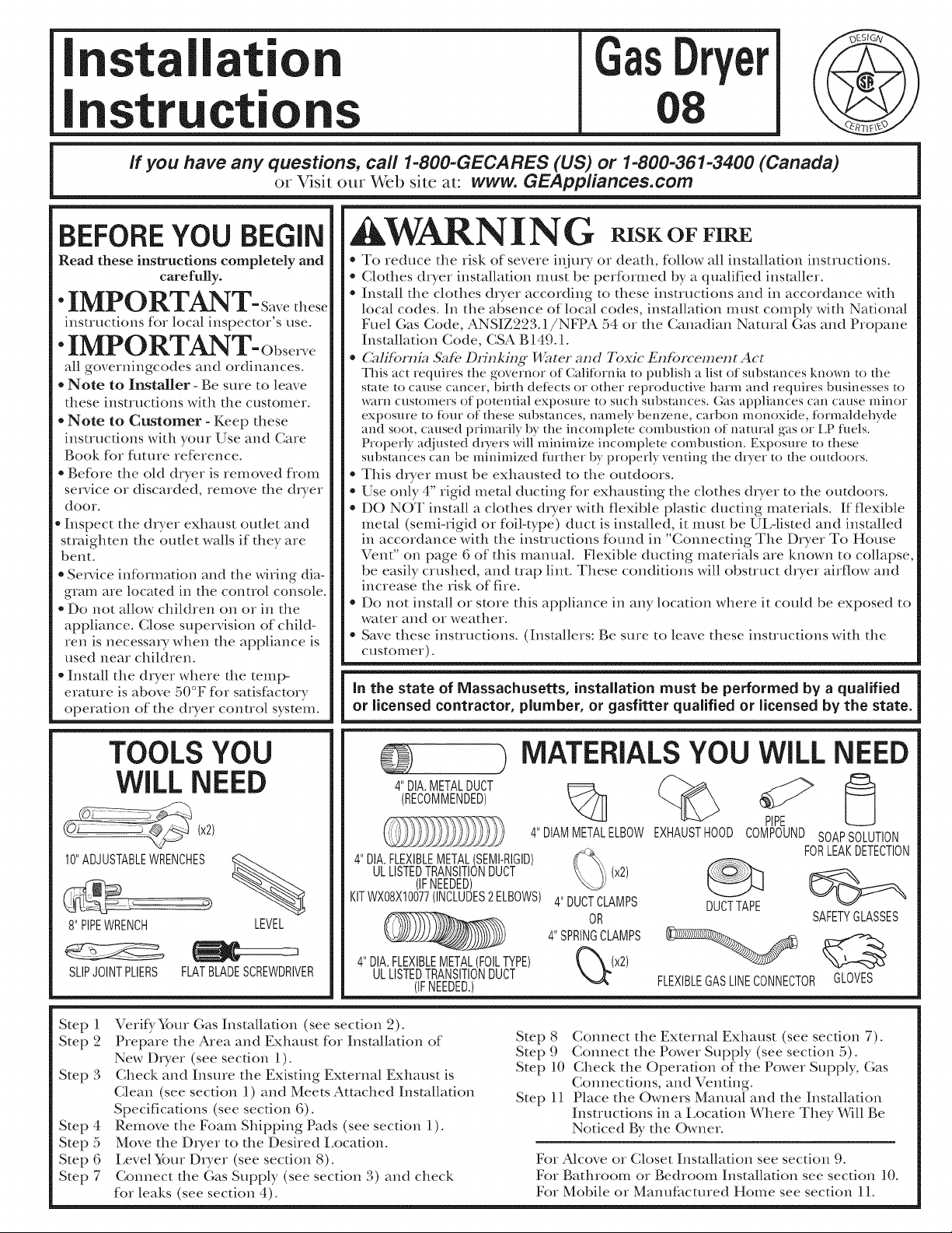
TOOLS YOU
WILL NEED
(x2)
10"ADJUSTABLEWRENCHES
8"PIPEWRENCH LEVEL
SLIPJOINTPLIERS FLATBLADESCREWDRIVER
Step 1
Step 2
Step 3
Step 4
Step 5
Step 6
Step 7
Verify, Yore Gas Installation (see section 2).
Prepare tlle Area and Exhaust for Installation of
New Dryer (see section 1).
Check and Insure tlle Existing External Exhaust is
Clean (see section 1) and Meets Attached Installation
Specifications (see section 6).
Remove the Foam Shipping Pads (see section 1).
Move the Dryer to tlle Desired Location.
Level Your Dryer (see section 8).
Connect the (;as Supply (see section 3) and check
for leaks (see section 4).
MATERIALSYOU WiLL NEED
4"DIA.METALDUCT e====_
(RECOMMENDED)
4"DIAMMETALELBOW
4"DIA.FLEXIBLEMETALSEMI-RIGID)
ULLSTEDTRANSTONDUCT
KITWX08X10077(INCLUDES2ELBOWS)
4"DIA.FLEXIBLEMETAL(FOILTYPE)
(IFNEEDED)
ULLISTEDTRANSITIONDUCT
(IFNEEDED.)
Step 8
Step 9
Step 10
Step 11
For Alcove or Closet Installation see section 9.
For Bathroom or Bedroom Installation see section 10.
For Mobile or Manufhctured Home see section 11.
PIPE [_
EXHAUSTHOOD COMPOUNDSOAPSOLUTION
(x2)
4"DUCTCLAMPS
OR
4"SPRINGCLAMPS _ _
Q_(x2) FLEXIBLEGASLINECONNECTORGLOVES
Connect tlle External Exhaust (see section 7).
Connect tile Power Supply (see section 5).
Check tlle Operation of tile Power Supply, Gas
Connections, and Venting.
Place tlle Owners Manual and the Installation
Instructions in a Location Where They Will Be
Noticed By tile Owner.
DUCTTAPE
FORLEAKDETECTION
SAFETYGLASSES
Page 2
Installation instructions
Minimum Clearance Other Than Alcove or Closet Installation
Minimum clearance m combustible surfhces and for air opening are: 0 in. clearance bofl_ sides and 1 in. rear. Consideration
must be given m provide adequate clearance for proper operation and service.
FT]PREPARING FOR iNSTALLATiON
OF NEW DRYER
TIP: Install your dryer before installing your washer,
This will allow better access when installing dryer exhaust,
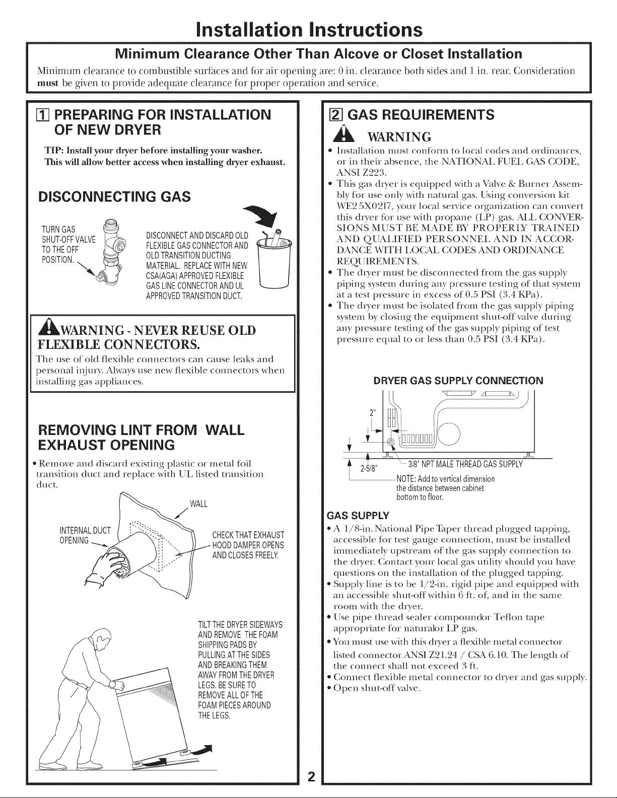
DiSCONNECTiNG GAS
TURNGAS
SHUT-OFFVALVE Id_
TOTHEOFF LL_._:q:v
a'k
_WARNING - NEVER REUSE OLD
FLEXIBLE CONNECTORS.
The use of okt flexible connectors can cause leaks and
personal ii_iury. Always use new flexible connectors when
installing gas appliances.
DISCONNECTANDDISCARDOLD_/__
FLEXIBLEGASCONNECTORAND
OLDTRANSITIONDUCTING
MATERIAL.REPLACEWITHNEW
CSA(AGA)APPROVEDFLEXIBLE
GASLINECONNECTORANDUL
APPROVEDTRANSITIONDUCT.
_q GAS REQUIREMENTS
WARNING
* Installation IIIUSE conf()l'IIl tO local codes and ordinances,
or in their absence, the NATIONAL FUEL (;AS CODE,
ANSI Z223.
* This gas dryer is equipped with a Valve & Burner Assem-
bly for use only with natural gas. Using conversion kit
WE2 5X0217, your local smwice organization can convert
this dwer for use with propane (LP) gas. ALL CONWER-
SIONS MUST BE MADE BY PROPERLY TRAINED
AND QUALIFIED PERSONNEL AND IN ACCOR-
DANCE WITH LOCAL CODES AND ORDINANCE
REQUIREMENTS.
* The dxyer must be disconnected flom the gas supply
piping system during any pressure testing of that system
at a test pressure in excess of 0.5 PSI (3.4 KPa).
* The dryer must be isolated flom the gas supply piping
system by closing the equipment shut-offvalve during
any pressure testing of the gas supply piping of test
pressme equal to or less than 0.5 PSI (3.4 KPa).
DRYER GAS SUPPLY CONNECTION
REMOVING LiNT FROM WALL
EXHAUST OPENING
* Remove and discard existing plastic or metal foil
transition duct and replace with UL listed transition
duct.
WALL
/
INTERNALDUCT CHECKTHATEXHAUST
OPENING HOODDAMPEROPENS
ANDCLOSESFREELY.
TILTTHEDRYERSIDEWAYS
ANDREMOVETHEFOAM
SHIPPINGPADSBY
PULLINGATTHESIDES
ANDBREAKINGTHEM
AWAYFROMTHEDRYER
LEGS.BESURETO
REMOVEALLOFTHE
FOAMPIECESAROUND
THELEGS.
" 3/8"NPTMALETHREADGASSUPPLY
l 2-5/8"
NOTE:Addtoverticaldimension
thedistancebetweencabinet
bottomto floor.
GAS SUPPLY
* A 1/8-in. National Pipe Taper thread plugged rapping,
accessible for test gauge connection, must be installed
immediately upstream of the gas supply connection to
the dryer. Contact your local gas utility should you have
questions on the installation of the plugged tapping.
* Supply line is to be 1/2-in. rigid pipe and equipped with
an accessible shut-off within 6 fL oL and in the same
room with the dwer.
* Use pipe thread sealer compoundor Teflon rope
appropriate for naturabr LP gas.
* You must use with this dryer a flexible metal connector
listed connector ANSI Z21.24 / CSA 6.10. The length of
the connect shall not exceed 3 fL
* Connect flexible metal connector to dryer and gas supply.
* Open shut-off valve.
2
Page 3
Installation
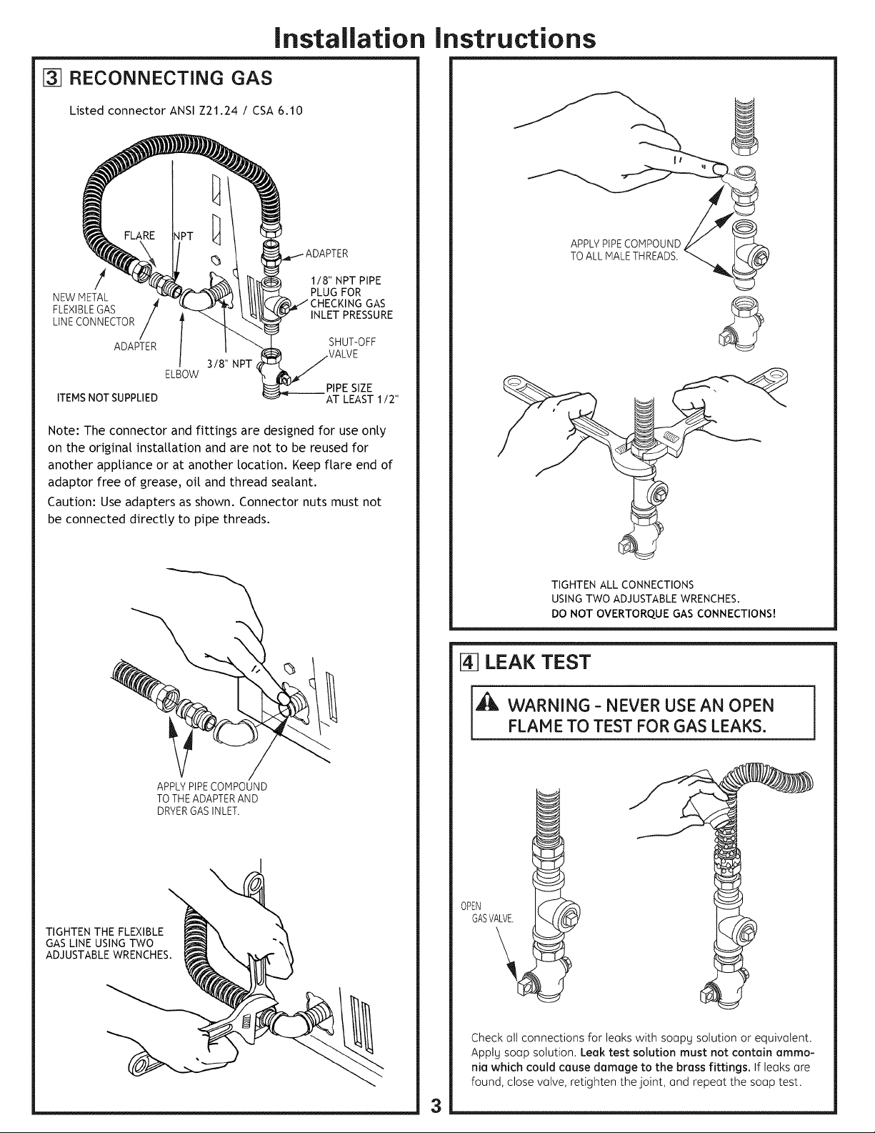
[] RECONNECTING GAS
Listed connector ANSI Z21.24 / CSA 6.10
118" NPT PIPE
NEWMETAL PLUG FOR
FLEXIBLEGAS INLET PRESSURE
LINECONNECTOR
ADAPTER
3/8" NPT
ELBOW
ITEMSNOT SUPPLIED AT LEAST 1/2"
Note: The connector and fittings are designed for use onty
on the original insta[tation and are not to be reused for
another appliance or at another location. Keep flare end of
adaptor free of ]rease, oi[ and thread sealant.
Caution: Use adapters as shown. Connector nuts must not
be connected directly to pipe threads.
GAS
SHUT-OFF
PIPE SIZE
Instructions
APPLYPiPECOMPOUND
TOALL MALETHREADS.
APPLYPIPECOMPOUND
TOTHEADAPTERAND
DRYERGASINLET.
TIGHTEN THE FLEXIBLE
GASLINE USING TWO
ADJUSTABLEWRENCHES.
TIGHTEN ALL CONNECTIONS
USINGTWO ADJUSTABLEWRENCHES.
DO NOT OVERTORQUE GAS CONNECTIONS!
LEAK TEST
[,_ WARNING - NEVER USE AN OPEN
FLAME TO TEST FOR GAS LEAKS.
OPEN
GASVALVE.
Check alt connections for leaks with soapg solution or equivalent.
Apply soap solution. Leak test solution must not contain ammo-
nia which could cause damage to the brass fittings. If leaks are
found, close valve, retighten the joint, and repeat the soap test.
3
Page 4

Installation
instructions
[] ELECTRICAL CONNECTION
iNFORMATiON
WARNING- TO REDUCE THE RISK OF
FIRE, ELECTRICAL S HOCK, AND PERSONAL
INJURY:
* DO NOT USE AN EXTENSION CORD CRAM
ADAPTER PLUG WITH THIS APPLIANCE.
D1yer must be electrically grounded in accordance with
local codes and ordinances, or in tile absence of local
codes, in accordance with tile NATIONAL ELECTRI-
CAL CODE, ANSI/NFPA NO. 70.
ELECTRICAL REQUIREMENTS
Tiffs appliance must be supplied with 120V, 60Hz, and com_ected
to a properly grounded branch circuit, protected by a 15- or 20-
amp circuit breaker or time-delay fi_se. If electrical supply provid-
ed does not meet the abo_e specifications, it is recommended that
a licensed electrician install an approved outlet.
_WARNING - THIS DRYER IS EQUIPPED
A THREE-PRONG (GROUNDING) PLUG FOR
YOUR PROTECTION AGAINST SHOCK
HAZARD AND SHOULD BE PLUGGED
DIRECTLY INTO A PROPERLY GROUNDED
THREE-PRONG RECEPTACLE. DO NOT CUT
OR REMOVE THE GROUNDING PRONG
FROM THIS PLUG.
F6-]EXHAUST iNFORMATiON
_WARNING- IN CANADA AND IN THE UNITED
STATES, THE REQUIRED EXHAUST DUCT DIAMETER
IS 4 IN (102ram). DO NOT USE DUCT LONGER
THAN SPECIFIED IN THE EXHAUST LENGTH TABLE.
l_ sing exhaust longer than specified length wilh
- Increase the chying times and the energ F cost.
- Reduce the cho_er life.
The correct exhaust installation is YOUR RESPONSIBILITY,
Problems due to incorrect installation are not covered
by the warranty.
Remove and discard existing plastic or metal foil transition
duct and replace with I_L listed transition duct.
The MAXIMI_ M ALLOWABLE duct length and number of
bends of the exhaust system depends upon the type of duct,
number of turns, the type of exhaust hood (wall cap), and all
conditions noted below. The maximum duct length for rigid
metal duct is shown in the table below.
- Accumulate lint, creating a potential fire hazard.
EXHAUST LENGTH
RECOMMENDED MAXIMUM LENGTH
Exhaust Hood Types
No. of 90-o
Elbows
0
1
2
3
4
5
Recommended Use only for short
Rigid
Metal
150 Feet
135 Feet
125 Feet
115 Feet
105 Feet
95 Feet
run installations
4" DIA.
......_ 1"_ 2-I/2"
Rigid
Metal
125 Feet
115 Feet
105 Feet
95 Feet
85 Feet
75 Feet
ENSURE PROPER GROUND EXISTS BEFORE USE.
IFLOCALCODESPERMIT,
ANEXTERNALGROUNDWIRE
(NOTPROVIDED),WHICHMEETS
LOCALCODES,MAYBEADDED
BYATTACHINGTOTHEGREEN
GROUNDSCREWONTHEREAR
OFTHEDRYER,ANDTOAGROUNDED
METALCOLDWATERPIPEOROTHER
ESTABLISHEDGROUND.
EXHAUST SYSTEM CHECK LiST
HOOD OR WALL (AP
• Terminate in a manner to prevent back drafts or entry of birds or
other wildlife.
• Termination should present minimal resistance to the exhaust air flow
and should require little or no maintenance to prevent clogging.
• Never install a screen in or over the exhaust duct.This could cause lint build up.
• Wall caps must be installed at least 12 in. above ground level or any other
obstruction with the opening pointed down.
SEPARATION OF TURNS
For best perfermance, separate all turns by at least 4 ft. of straight duct,
including distance between last ttlrn and exhaust hood.
TURNS OTHER THAN 90 °
• One turn of 45 ° or less may be ignored.
• Two45 ° tt/rns should be treated as one 90° tt/rn.
• Each tt/rn over 45° should be treated as one 90° tt/rn.
SEALING OF JOINTS
* _Mljoints should be tight te avoid leaks. The male end of each section of
duct must point away flom the dryer.
* Do not assemble the ductwork with fasteners that extend into the duct.
They will serve as a collection point fer lint.
Duct joints can be made air and moisture-tight by wrapping the
overlapped joints with dt_ct rope.
Horizontal runs should slope down toward the outdoors _½inch per feot
iNSULATION
Duct work that runs through an unheated area or is near air conditioning
should be insulated to reduce condensation and lint build-t_p.
4
Page 5

Installation instructions
[_ EXHAUST CONNECTION
_ WARNING - TO REDUCE THE RISK
OF FIRE OR PERSONAL INJURY:
* This clothes dIyer must be exhausted to the outdoors.
, Use only 4" rigid metal ducting for the home exhaust
duct.
e Use only 4" rigid metal or Ui,-listed flexible metal
(semi-rigid or foil-type) duct to connect the d_yer to the
home exhaust duct. It must be installed in accordance
with the instructions found in "Connecting The D_Ter
To House Vent" on page 6 of this manual.
* Do not terminate exhaust in a chimney, a wall, a
ceiling, gas vent, crawl space, attic, under an enclosed
floor, or in any other concealed space of a building.
The accumulated lint could create a fire hazard.
* Never terminate the exhaust into a common duct with
a kitchen exhaust system. A combination of grease and
lint creates a potential fire hazard.
* Do not use duct longer than specified in the exhaust
length ruble. Longer ducts can accumulate lint,
creating a potential fire hazard.
* Never install a screen in or over the exhaust duct. This
will cause lint to accumulate, creating a potential fire
hazard.
* Do not assemble ducta,vork with any fasteners that
extend into the duct. These fasteners can accumulate
lint, creating a potential fire hazard.
* Do not obstruct incoming or exhausted air.
* Provide an access for inspection and cleaning of the
exhaust system, especially at turns and joints. Exhaust
system shall be inspected and cleaned at least once a year.
THiS DRYER COMES READY FOR REAR
EXHAUSTING. iF SPACE iS LiMiTED, USE
THE iNSTRUCTiONS iN SECTION 9 TO
EXHAUST DIRECTLY FROM THE SIDES OR
BOTTOM OF THE CABINET.
STANDARD REAR EXHAUST
{Vented above floor level)
ELBOWHIGHLY
RECOMMENDED
RECOMMENDED
CONFIGURATION
TOMINIMIZE
EXHAUST
BLOCKAGE.
ELBOWHIGHLY
RECOMMENDED-
NOTE: ELBOWS WiLL PREVENT DUCT
KiNKiNG AND COLLAPSING.
FS-]LEVELING DRYER
LEVEL
FRON_TO-BACK.
-_ LEVEL
SIDE-TO-SIDE.
STANDARD REAR EXHAUST
{Vented at floor level)
FORSTRAIGHTLINEINSTALLATION,CONNECTTHEDRYEREXHAUSTTO
THEEXTERNALEXHAUSTHOODUSINGDUCTTAPEORCLAMP.
CSA(AGA)APPROVED
NEWFLEXIBLEGAS
LINECONNECTOR
EXTERNAL
DUCT
OPENING
DUCTTAPEOR
DUCTCLAMP
NOTE:WESTRONGLYRECOMMENDSOLIDMETALEXHAUSTDUCTING.
HOWEVER,IFFLEXIBLEDUCTINGISUSEDITMUSTBEUL-LISTEDMETAL
NOTPLASTIC.
GAS
INLET
4"METALDUCT
(CUTTOPROPER
LENGTH)
DUCTTAPEOR
DUCTCLAMP
4LEVELINGLEGS
2ANTI-TIPLEGS
STANDTHEDRYERUPRIGHTNEARTHE
FINALLOCATIONANDADJUSTTHE4LEVELING
LEGSTOMATCHTHEHEIGHTOFYOURWASHER.
ADJUSTTHE2ANTI-TIPLEGSTOCONTACT
THEFLOOR.
5
Page 6

Installation instructions
CONNECTING THE DRYER
TO HOUSE VENT
RIGID METALTRANSITIONDUCT
* For best d,Ting perff_rmance, a rigid metal transition
duct is recommended.
* Rigid metal transitions ducts reduce the risk of crush-
ing and kinking.
UL-LISTEDFLEXIBLEMETAL(SEMI-RIGID) TRANSITION DUCT
e If rigid metal duct cannot be used, then UiAisted
flexible metal (semi-rigid) ducting can be used (Kit
WX08X10077).
*Never install flexible metal duct in walls, ceilings, floors
or other enclosed spaces.
*Total length of flexible metal duct should not exceed 8
feet (2.4m).
*For many applicanons, installing elbows at both the
dwer and the wall is highly recommended (see illustra-
tions below). Elbows allow the dwer to sit close to the
wall without kinMng and or crushing the transition
duct, maximizing dxTing performance.
*Avoid resnng the duct on sharp objects.
UL-LISTED FLEXIBLE METAL (FOIL-TYPE) TRANSITION DUCT
* In special installations, it may be necessai T to connect
the dwer to the house vent using a flexible metal (foil-
type) duct. A UL-listed flexible metal (fbil-type)duct
may be used ONLY in installations where rigid metal or
flexible metal (semi-rigid) ducting cannot be used AND
where a 4" diameter can be maintained throughout the
ennre length of the transinon duct.
* In Canada and the United States, only the flexible
metal(fbil-type) ducts that comply with the "Outline for
Clothes Dwer Transition Duct Subject 2158A" shall be
used.
* Never install flexible metal duct in walls, ceilings, floors
or other enclosed spaces.
* Total length of flexible metal duct should not exceed 8
feet (2.4m).
* Avoid resting the duct on sharp objects.
* For best dwing performance:
]. Slide one end of the duct over the clothes dwer
outlet pipe.
9. Secure the duct with a clamp.
3. With the dr}wr in its permanent position, extend the
duct to its fldl length. Allow 9" of duct to overlap the
exhaust pipe. Cut offand remove excess duct. Kee I)
the duct as straight as possible tot maximum airflow.
4. Secure the duct to the exhaust pipe with the other
clam p.
RECOMMENDED
SHIGHLY _>_i_":: _.__"
- RECOMMENDED_ ''_ \ ....
Do
EXCESSIVE
ALCOVE OR CLOSET INSTALLATION
* If your dwer is approved for installation in an alcove or closet,
it will be stated on a label on ti_e &Ter back.
* The diyer MUST be vented to the outdoors. See the
EXHAUST INFORMATION section.
* Minimum clearance be/ween dryer cabinet and adjacent ,_vdls
or other surf:does is:
0 in. either side
3 in. flont and rear
* Minimum vertical space flom floor to overhead cabinets,
ceiling, etc. is 52 in.
* Closet doors must be louvcred or o/herwise vcntilamd and must
contain a minimum of 60 sq. in. of open area equally distribumd.
If the closet contains bo/h a washer and a dr_vr, doors must
contain a minimum of 120 sq.in, of open area equally distribumd.
* The closet should be vented to the outdoors to prevent
gas pocketing in case of a gas leak in the supply line.
* No other tirol-burning appliance shall be installed in the
same closet wi/h the dwer.
If0-] BATHROOM OR BEDROOM
INSTALLATION
e The dryer MUST be vented to the outdoors. See
EXHAUST INFORMATION section 6.
* The installation must conform with local codes or, in
the absence of local codes, with the NATIONAL FUEL
GAS CODE, ANSI Z223.
MOBILE OR MANUFACTURED
HOME INSTALLATION
e Installa/ion must confbrm to the MANUFACTURED HOME
CONSTRUCTION & SAFETY STANDARD, TITLE 24, PART
32-80 or, when such standard is not applicable, with AMERICAN
NATIONAL STANDARD FOR MOBILE HOME, NO. 501B.
* The dryer MUST be vented to the outdoors with the termina-
tion securely fastened to the mobile home structure. (See
EXHAUST INFORMATION section 6.)
* The vent MUST NOT be terminated benea/h a mobile or
manuf:dcnned home.
* The vent duct material MUST BE METAl,.
* FdT 14-D346-33 MUST be used to attach the dwer securely
to the struc/ure.
* The vent MUST NOT be connected to any other duct, vent,
or chimney.
* Do not use sheet metal screws or other refastening devices
which extend into the interior of ti_e exhaust vent.
* Provide an opening with a flee area of at least 2:5 sq. in.or
introduction of outside air into the dwer room.
6
Page 7

Installation Instructions
I_ DRYER EXHAUST TO LEFT OR
BOTTOM CABINET
WARNING- BEFORE PERFORMING
THIS EXHAUST INSTALLATION, BE SURE
TO DISCONNECT THE DRYER FROM ITS
ELECTRICAL SUPPLY. PROTECT YOUR
HANDS AND ARMS FROM SHARP EDGES
WHEN WORKING INSIDE THE CABINET.
BE SURE TO WEAR GLOVES
REMOVE
SCREW
ANDSAVE.
O_ REMOVE
DESIRED
KNOCKOUT
(ONEONLY).
Detach and remove the bottom or left side knockout as
desired. Remove the screw inside the dwer exhaust duct
and save. Pull the duct out of the duet.
FIXINGHOLE
ADDING NEW DUCT
FIXING
HOLE
PORTION"A"
LEFTSIDE
EXHAUST
Reconnect dm cut portion (A) of the duct to the blower
housing. Make sure that the shortened duct is aligned with
the tab in the base. Use the screw saved previously to secure
the duct in place through the tab on the appliance base.
ADDING ELBOW AND DUCT FOR
EXHAUST TO LEFT SIDE OF CABINET
• Preassemble 4" elbow with 4" duct. Wrap duct tape
around joint.
• Insert duct assembly, elbow first, through the side opening
and connect the elbow to the dwer internal duct.
CAUTION: Be sure not to pull or damage the
electrical wires inside the dryer
when inserting the duct,
B A
9"
Cut the duct as shown and kee I) portion A.
TAB LOCATION
BENDTAB
UP450
Through the real" opening, locate the tab in the middle of
the appliance base. Lift the tab to about 45° using a fiat
blade screwdriver.
J_
// TAPE
• Apply duct tape as shown on the joint between the diTer
internal duct and the elbow.
DUCT
TAPE
CAUTION:
Internal duct joints must be
they may separate and cause
__ secured with tape, otherwise
7
a safety hazard.
DUCT
Page 8

Installation
Instructions
ADDING ELBOW FOR EXHAUST
THROUGH BOTTOM OF CABINET
. Insert die elbow dn'ough the rear opening and connect
it to tile dlyer internal duct.
. Apply duct tape oil the joint between tile dryer internal
duct and elbow, as shown on page 7.
CAUTION:
Internal duct joints must be secured with tape,
otherwise they may separate and cause a
safety hazard.
ADDING COVER PLATE TO REAR
OF CABINET
[_ CHANGING DIRECTION OF
DOOR OPENING
REMOVE4HOLEPLUGSAND
REMOVE4
HINGESCREWS.
PLACETHEMINTHEHOLES
ONTHEOPPOSITESIDE.
PLATE
(KIT WE1M454)
Comlect standard metal elbows and ducts to complete rile
exhaust system. Cover back opening with a plate (Kit
WE1M454) available Kom your local service provider.
Place dryer in final iocauon.
,_ WARNING- NEVER LEAVE THE
BACK OPENING WITHOUT THE PLATE.
ROTATEDOOR1800
ANDREINSTALL.
[_ SERVICING
_k WARNING- LABEL ALL WIRES
PRIOR TO DISCONNECTION WHEN
SERVICING CONTROLS. WIRING
ERRORS CAN CAUSE IMPROPER AND
DANGEROUS OPERATION AFTER
SERVICING/INST ALLATION.
For Questions on Installadon, Call: 1-800-626-2000 (US) or
500A436POO8 1-800-561-3344 (Canada). Pub. # 31-16227 8
For replacement parts and other infornmtion, refer to
Owner's Mammi for servicing phone mmfl)ers.
 Loading...