

GE DISR473TWW Technician Service Manual

g
________________________________________________________
GE Appliances Service Training
TECHNICIAN
SERVICE MANUAL
Dryer
MODEL:
DISR473TWW
CIWE1001E
FEBRUARY 2000

CAUTION !
DISCONNECT POWER CORD
BEFORE SERVICING THIS APPLIANCE!
RECONNECT ALL GROUNDING DEVICES
IMPORTANT SAFETY NOTICE !
This service information is intended for use by
individuals possessing adequate backgrounds of
electrical, electronic and mechanical experience.
Any attempt to repair this major appliance may
result in personal injury and property damage. The
manufacturer or seller cannot be responsible for
the interpretation of this information nor can it
assume any liability in connection with its use.
THE MANUAL COVERS THE
FOLLOWING MODELS
MODEL# COUNTRY
DISR473TWW AUSTRALIA
N/A BANGLADESH
N/A CHINA
N/A HONG KONG
N/A INDIA
N/A INDONESIA
N/A JAPAN
N/A KOREA
N/A MALAYSIA
N/A PAKISTAN
N/A PHILIPPINES
N/A SINGAPORE
N/A TAIHITI
N/A TAIWAN
N/A THAILAND
N/A VIETNAM
I. SPECIFICATION
ITEMS SPECIFICATIONS
Colour WW, AA
Dimensions (Inches) (W x H x D) 27 x 42 x 28¼
Total # of Cycles 7
Electrical 240 VAC, 50 Hz, 20 amps
Timed Dry (Min) 80
Capacity (kg) 8
Heat Selection 4
Page 4

II. THEORY OF OPERATION
2.1 How a Dryer Works
All dryers, whether gas or electric, operate
according to the same principle they remove
moisture from damp clothes by bringing the
clothes in contact with a flow of heated air.
Mechanically the clothes must tumble to expose
all of their surfaces to heat, and the heated air
must be circulated within the dryer and then
vented.
Switches, timers and thermostats regulate the
air temperature and duration of the drying cycle.
When the start button is activated with the dryer
door closed, the motor is activated. The motor is
connected to the drum by a drive belt. This
drive belt rotates the drum through a pulley
system attached to the motor shaft. The drum
itself is supported by a bearing and slides at the
front.
2.2 Axial Air Flow
Air is pulled into the cabinet from the rear, and
drawn up across the heaters located behind the
drum. This hot air is pulled through the drum
rear, across the clothes load, through the lint
filter and down the trap direct into the blower.
From the blower the air is pushed out the
exhaust system.
In electric dryers, the heat source is not
energized until the drive motor start turning.
Both the timer and thermostats energize coiled
resistance heaters. The temperature selector
switched control the number of heaters
energized.
Page 5
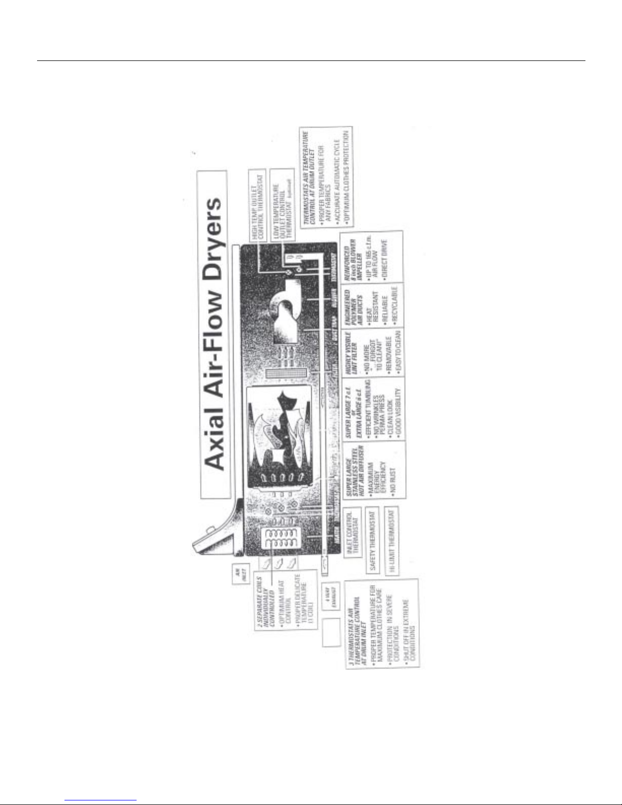
2.2 Axial Air-Flow Dryers
II. THEORY OF OPERATION
Page 6

2.2 Air Flow Diagram
II. THEORY OF OPERATION
Page 7
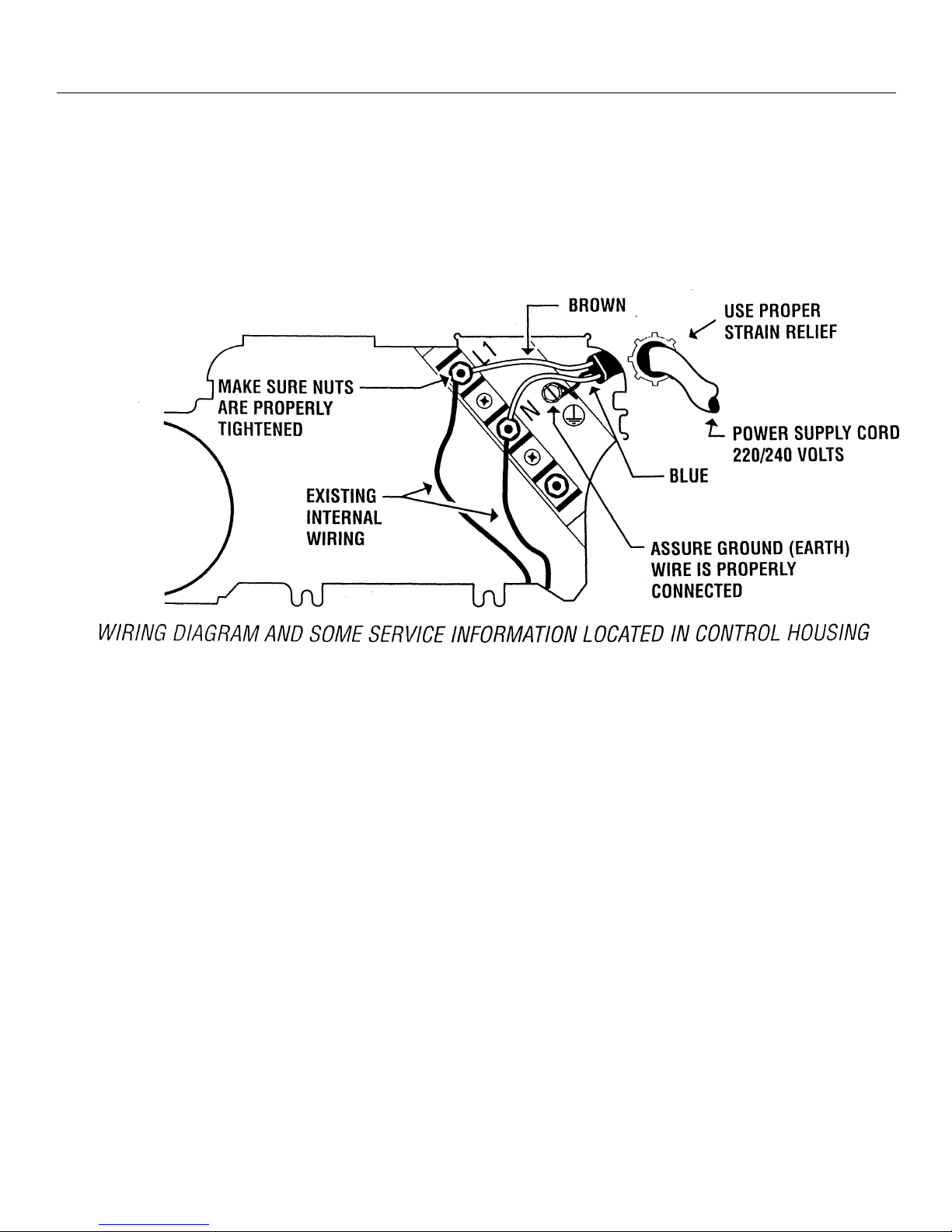
III. GROUNDING EQUIPMENT
IF THE DRYER IS SUPPLIED WITH A FLEXIBLE POWER CORD
Plug the cordset into its own separate grounded out. Do Not, UNDER ANY CIRCUMSTANCES, CUT OR REMOVE
THE GROUND PRONG FROM THE POWER CORD.
Page 8
IV. DRYER CONSTRUCTION AND SERVICE
Control Panel : Provide access to timer & switches.
Service : Remote four #15 Torx screws from top. Switches & timer are tab interlock. The timer is
not technical serviceable.
Cabinet : 4 x Parts
2 - Side painted panels with knowckouts for side exhaust
L - Shape galvanized steel chassis : Back - Base Front
BACK with louvers for air entry and Service access panel
BASE with leveling legs and knockout for buttom exhaust
Service : All cabinet parts are hold together by screws.
Top : Upswept, galvanized steel, power painted
Service : Remove two screws in door opening and lift it up
Door : Embedded in front cabinet
Two parts : Front door and inner door hold by screws
Plugs 2 hinges and a latch strike
Service : Just loose hinge screws in key holes
Front : One-piece construction
Outside : Filter snapped in
Inside : Latch
Front seal and felt
Drum slide
Trap duct
Service : Front - Remove the top
Remove screws on the inside right and left of cabinet
Lift it up from the two supports it rest on at the bottom
Note : The drum must be supported by one hand while removing the front.
Disconnect wires from door switch
Front Seal - Clip on trap duct
Front Felt - Clip on door opening flange
Trap Duct - Clip on door opening flange
Drum Slides - The teflon slides are removable
There are two color slides (grey & white) - do not mix
Do not lubricate the slides
Page 9

IV. DRYER CONSTRUCTION AND SERVICE
Drum : 7 x Parts
Belt
One-piece drum (front Wrapper Rear)
3 baffles
Diffuser
Shaft
Bearing
Service : Drum Removal Remove belt from idler pulley
Release idler arm (belt tension system)
Lift up the drum or through port at right
Reach under the drum behind the motor
Pull idler arm at the pulley end down
Hook the idler end on the motor mount bracket
The bracket has a hook that will hold idelr arm and allow to easily place or remove the belt
over the idelr pulley and motor pulley.
Slide the drum out
Baffles Hold with 3 screws
Diffuser Secure with 4 x Torx # 15 screws
Shaft bracket Same screw as the diffuser. Be careful when re-installing the drum that
the bearing and washers are in place.
Motor / Blower : Motor
Motor mount bracket
Blower housing
Blower
Idler spring
Service : Motor, blower, idler swith are all mounted on motor bracket.
Unscrew the two long screws (9 cm) securing the motor bracket to the blower housing and
two 3/8 hex. Screws through the base.
Heater : Heater assembly
Hi limit thermostat at 2:00 oclock
Safety control thermostat
Control thermos
Service : Heater - The heater is not reastringale and must be replaced as a complete part.
Thermostat - Secure with screw and tab.
Its mounted with 4 screws.
Page 10
 Loading...