

GE DGP Series, DGP ABA-0005, DGP AAA-0101, DGP AAA-0102 Instruction Manual
g
GEPowerManagement
DGP
Digital Generator Protection Relay™
Instruction Manual
DGP Revisions:V210.12000P
V210.10000F
V211.32000J
V210.22000D
Manual P/N: GEK-100666D
Copyright © 2000 GE Power Management
All relays must be powered up at least once per year
to avoid deterioration of electrolytic capacitors and
NOTE
GE Power Management
215 Anderson Avenue, Markham, Ontario
Canada L6E 1B3
Tel: (905) 294-6222 Fax: (905) 294-8512
Internet: http://www.GEindustrial.com/pm
subsequent relay failure.
Manufactured under an
ISO9002 Registered system.


These instructions do not purport to co ve r all de tails o r variat ions in e quipment
g
g
g
nor provide for every possible contin
installation, operation, or maintenance. Should further information be desired
or should particular problems arise which are not covered sufficiently for the
purchaser’s purpose, the matter should be refe rred to the General Electric
Company.
To the extent required the products described herein meet applicable ANSI,
ency to be met in connection with
IEEE, and NEMA standards; but no such assurance is
local codes and ordinances because they vary
reatly.
iven with respect to


TABLE OF CONTENTS
1. PRODUCT DESCRIPTION
1.1 GETTING STARTED
1.1.1 UNPACKING THE RELAY.........................................................................1-1
1.1.2 ORDER CODES & SELECTION GUIDE................................................... 1-2
1.1.3 SPECIAL MODELS....................................................................................1-3
DGP***AAA-0101 and DGP***AAA-0102....................................................... 1-3
DGP***ABA-0005 ...................................................................... .... .... .. .... .. .....1-3
1.1.4 DEC 1000 CONTACT EXPANSION UNIT.................................................1-3
1.2 INTRODUCTION
1.2.1 GENERAL..................................................................................................1-4
1.2.2 APPLICATION...........................................................................................1-4
1.3 PROTECTION FEATURES
1.3.1 DESCRIPTION.......................................................................................... 1-6
1.3.2 STATOR DIFFERENTIAL (87G)................................................................1-7
1.3.3 CURRENT UNBALANCE (46T)................ .................................................1-7
1.3.4 LOSS OF EXCITATION (40) ..................................................................... 1-7
1.3.5 ANTI-MOTORING (32)..............................................................................1-8
1.3.6 TIME OVERCURRENT WITH VOLTAGE RESTRAINT 51V.....................1-8
1.3.7 STATOR GROUND (64G/27TN)............................................................... 1-8
1.3.8 GROUND OVERCURRENT (51GN) ........................... ..............................1-9
1.3.9 OVEREXCITATION (24)............. .................................................. ............. 1-9
1.3.10 OVERVOLTAGE (59)..............................................................................1-10
1.3.11 UNDERVOLTAGE (27)......................... ...................................................1-10
1.3.12 OVER AND UNDERFREQUENCY (81)... ...............................................1- 1 0
1.3.13 VOLTAGE TRANSFORMER FUSE FAILURE (VTFF)............................ 1-10
1.3.14 ACCIDENTAL ENERGIZATION (AE)...................................................... 1-11
1.4 OTHER FEATURES
1.4.1 INPUTS....................................................................................................1-17
1.4.2 OUTPUT RELAYS.................................. ................................................. 1-17
1.4.3 START-UP SELF-TESTS ........................................................................1-18
1.4.4 RUN-TIME SELF-TESTS................ ........................................ ................. 1-18
1.4.5 ADAPTIVE SAMPLING FREQUENCY....................................................1-19
1.4.6 TRIP CIRCUIT MONITOR.................................................... ...................1-19
1.4.7 SEQUENCE OF EVENTS....................................... ......................... ....... 1-19
1.4.8 TIME SYNCHRONIZATION..................................................................... 1-20
1.4.9 FAULT REPORT & OSCILLOGRAPHY DATA........................................1-21
1.4.10 LOCAL MAN -MACHINE IN TERFACE............ .............. ............. .. ............ 1-21
1.4.11 LOCAL PRINTER ........................ .. .............. . .............. .. ............. .. ............ 1-21
1.4.12 REMOTE COMMUNICATIONS.......... .....................................................1-22
1.4.13 REMOTE CONTROL............................................................................... 1-22
1.4.14 PASSWORD PROTECTION........................... ......................... ............... 1-22
1.4.15 REMOTE COMMUNICATIONS – MODBUS PROTOCOL...................... 1-22
1.5 ELEMENTARY DIAGRAMS
2. CALCULATION OF
SETTINGS
2.1 GENERAL
2.1.1 DESCRIPTION.......................................................................................... 2-1
2.2 CONFIGURATION SETTINGS
2.2.1 DESCRIPTION........................................................................................ 2-10
101: UNITID – UNIT ID NUMBER ................................................................2-10
102: SYSFREQ – SYSTEM FREQUENCY .................................................. 2-10
103: SEL TVM – SELECT TRIP VOLTAGE MONITORING......................... 2-10
104: SEL TCM – SELECT TRIP CURRENT MONITORING........................ 2-10
105: SELPRIM – SELECT PRIMARY/SECONDARY UNITS .......................2-10
106: CT RATIO – CURRENT TRANSFORMER RATIO.............. .. ...............2-10
GE Power Management DGP Digital Generator Protection System
i

TABLE OF CONTENTS
107: VT RATIO – VOLTAGE TRANSFORMER RATIO................................ 2-10
108: COMMPORT – COMMUNICATIONS PORT........................................ 2-11
109: PHASE – PHASE DESIGNATION........................................................ 2-11
110: TIMESYNC – TIME SYNCHRONIZATION SOURCE........................ ... 2-11
111: NUM FLTS – NUMBER OF FAULT EVENTS....................................... 2-11
112: PREFLT – PREFAULT CYCLES.......................................................... 2-12
113: OSC TRIG – EXTERNAL OSCILLOGRAPHY TRIGGER ....................2-12
114: NOM VOLT – NOMINAL VOLTAGE..................................................... 2-12
115: RATEDCUR – RATED CURRENT.......................................................2-12
116: VT CONN – VOLTAGE TRANSFORMER CONNECTION................... 2-12
117: NCTRATIO – NEUTRAL CURRENT TRANSFORMER RATIO ........... 2-12
2.2.2 EXAMPLE CONFIGURATION SETTINGS ..............................................2-12
2.3 PROTECTION FUNCTION SETTINGS
2.3.1 TRIP AND ALARM OUTPUT RELAYS .................................................... 2-13
2.3.2 STATOR DIFFERENTIAL 87G................................................................2-13
2.3.3 CURRENT UNBALANCE ALARM 46A....................................................2-18
2.3.4 CURRENT UNBALANCE TRIP 46T... ................... ............................... ... 2-18
2.3.5 LOSS OF EXCITATION 40, 40-1, 40-2 ...................................................2-20
2.3.6 ANTI-MOTORING (REVERSE POWER).................................................2-21
2.3.7 OVERCURRENT WITH VOLTAGE RESTRAINT (51V)..........................2-22
2.3.8 STATOR GROUND FAULT 64G-1.......................................................... 2-28
2.3.9 STATOR GROUND FAULT 64G-2.......................................................... 2-28
2.3.10 STATOR GROUND FAULT 27TN...........................................................2-28
2.3.11 OVEREXCITATION ALARM (VOLTS/HERTZ: 24A) ............................... 2-29
2.3.12 OVEREXCITATION TRIP (VOLTS/HERTZ: 24T).................................... 2-29
2.3.13 OVERVOLTAGE 59.................................................................................2-34
2.3.14 UNDERVOLTAGE CUTOFF OF 81......................................................... 2-36
2.3.15 UNDERFREQUENCY 81-U.....................................................................2-36
2.3.16 OVERFREQ U EN CY 81-O ......................... .. ........................................ .. .. 2-36
2.3.17 DIGITAL INPUT DI...................................................................................2-36
2.3.18 VOLTAGE TRANSFORMER FUSE FAILURE VTFF.............................. 2-37
2.3.19 ACCIDENTAL ENERGIZATION AE ........................................................ 2-37
2.3.20 GROUND OVERCURRENT 51GN................... ............................ ........... 2-38
2.3.21 UNDERVOLTAGE 27..............................................................................2-38
2.4 COMMISSIONING
2.4.1 DGP***AAA SETTINGS TABLE.............................................................. 2-41
2.4.2 DGP***ABA SETTINGS TABLE ..............................................................2-46
2.4.3 DGP***ACA SETTINGS TABLE ..............................................................2-51
3. HARDWARE
DESCRIPTION
ii
3.1 CASE ASSEMBLY
3.1.1 WARNING.................................................................................................. 3-1
3.1.2 CONSTRUCTION......................................................................................3-1
3.1.3 ELECTRICAL CONNECTIONS & INTERNAL WIRING............................ .3-1
3.1.4 IDENTIFICATION ......................................................................................3-1
3.2 CIRCUIT BOARD MODULES
3.2.1 WARNING.................................................................................................. 3-4
3.2.2 BASIC CONSTRUCTION.......................................................................... 3-4
3.2.3 IDENTIFICATION ...................................................... ................................3-4
3.3 XTM TEST PLUGS
3.3.1 DESCRIPTION .......................................................................................... 3-6
3.3.2 TERMINAL DESIGNATION........... .......................... ......................... ......... 3-6
3.3.3 XTM TEST-CIRCUIT CONNECTIONS....................................... ............... 3-6
3.3.4 T EST PL U G INSERTION ........... .. ........................................ .. ................... 3-6
DGP Digital Generator Protection System
GE Power Management

TABLE OF CONTENTS
3.4 INSTALLATION
3.4.1 RECEIVING, HANDLING, & STORAGE.................................................... 3-7
3.4.2 ENVIRONMENT........................................................................................ 3-7
3.4.3 MOUNTING ............................................................................................... 3-7
3.4.4 EXTERNAL CONNECTIONS..... ......................... ......................... ............. 3-7
3.4.5 EXTERNAL CONNECTIONS TEST..........................................................3-7
3.4.6 SURGE GROUND CONNECTIONS.................... ........................... ........... 3-7
4. ACCEPTANCE TESTS
4.1 INTRODUCTION
4.1.1 WARNING..................................................................................................4-1
4.1.2 GENERAL..................................................................................................4-1
a GENERAL TESTS.....................................................................................4-1
b PROTECTION TESTS................ ......................... ......................... ............. 4-1
4.2 TEST PREPARATION
4.2.1 TEST EQUIPMENT...................................................................................4-2
4.2.2 DRAWINGS & REFERENCES..................................................................4-2
a DRAWINGS............................................................................................... 4-2
b REFERENCES..........................................................................................4-2
4.2.3 EQUIPMENT GROUNDING......................................................................4-2
4.2.4 REQUIRED SETTINGS......... .......................... ......................... ................. 4-2
4.3 GENERAL INSTRUCTIONS
4.3.1 PROCEDURE............................................................................................4-3
4.3.2 SETTING CHANGES................................................................................. 4-3
4.3.3 ENTERING THE TEST MODE.................................................................. 4-4
4.3.4 EXITING THE TEST MODE......................................................................4-4
4.4 USING GE-LINK
4.4.1 DESCRIPTION.......................................................................................... 4-5
4.4.2 HARDWARE SETUP................................................................................. 4-5
4.4.3 SO FTWARE SETU P........... .. ............. .. .. ............. .. ............. .. .. .................... 4-5
a LOAD & START GE-LINK..........................................................................4-5
b SET UP A NEW TEST UNIT......................................................................4-5
4.4.4 RELAY SETUP.......................................................................................... 4-6
4.4.5 LOGGING INTO THE RELAY....................................................................4-6
4.4.6 SETTING CHANGES................................................................................. 4-7
4.4.7 ENTERING THE TEST MODE.................................................................. 4-7
4.4.8 EXITING THE TEST MODE......................................................................4-7
4.5 INITIAL TEST SETUP
4.5.1 DESCRIPTION.......................................................................................... 4-8
4.6 GENERAL RELAY TESTS
4.6.1 NOTE......................................................................................................... 4-9
4.6.2 T1: MMI STATUS AND DISPLAY TESTING.............................................4-9
a STATUS CHECK ....................................................................................... 4-9
b WARNING STATUS .................................................................................. 4-9
c DISPLAY TEST........................................................................................ 4-10
4.6.3 T2: DIGITAL OUTPUT TESTS ................................................................4-11
4.6.4 T3: DIGITAL INPUT TESTS ....................................................................4-13
4.6.5 T4: AC SYSTEM INPUT TEST ................................................................ 4-15
4.7 PROTECTION TESTS
4.7.1 DESCRIPTION........................................................................................ 4-17
4.7.2 T5: GENERATOR DIFFERENTIAL TEST 87G.......................................4-18
4.7.3 T6: CURRENT UNBALANCE ALARM 46A ............................................. 4-20
4.7.4 T7: CURRENT UNBALANCE TRIP 46T.................................................. 4-20
4.7.5 T8: LOSS OF FIELD PROTECTION ZONE 1 40-1.................................4-22
4.7.6 T9: LOSS OF FIELD PROTECTION ZONE 2, 40-2................................4-23
GE Power Management DGP Digital Generator Protection System
iii

TABLE OF CONTENTS
4.7.7 T10: ANTI-MOTORING & SEQUENTIAL TRIP SUPERVISION 32-1 ..... 4-23
4.7.8 T11: ANTI-MOTORING 32-2 ................................................................... 4-24
4.7.9 T12: TIME OVERCURRENT WITH VOLTAGE RESTRAINT 51V ..........4-24
4.7.10 T13: ACCIDENTAL ENERGIZA TION AE ................................................ 4-25
4.7.11 T14: STATOR GROUND ZONE 1 64G1 ................................................. 4-27
4.7.12 T15: STATOR GROUND ZONE 2 64G2 ................................................. 4-28
4.7.13 T16: VOLTS/HERTZ OVEREXCITATION ALARM 24A..........................4-30
TEST RESULTS:..........................................................................................4-30
4.7.14 T17: VOLTS/HERTZ OVEREXCITATION TRIP 24T...............................4-31
4.7.15 T18: POSITIVE-SEQUENCE OVERVOLTAGE 59..................................4-32
TEST RESULTS...........................................................................................4-32
4.7.16 T19: UNDERFREQUENCY UNIT #1 81-1U ............................................4-33
4.7.17 T20: UNDERFREQUENCY UNIT #2 81-2U ............................................4-33
4.7.18 T21: UNDERFREQUENCY UNIT #3 81-3U ............................................4-34
4.7.19 T22: UNDERFREQUENCY UNIT #4 81-4U ............................................4-34
4.7.20 T23: OVERFREQUENCY UNIT #1 81-1O ...............................................4-35
4.7.21 T24: OVERFREQUENCY UNIT #2 81-2O ...............................................4-35
4.7.22 T25: OVERFREQUENCY UNIT #3 81-3O ...............................................4-36
4.7.23 T26: OVERFREQUENCY UNIT #4 81-4O ...............................................4-36
4.7.24 T27: VOLTAGE TRANSFORMER FUSE FAILURE VTFF ...................... 4-37
4.7.25 T28: TOC GROUND OVERCURRENT 51GN.........................................4-37
4.7.26 T29: UNDERVOLTAGE 27......................................................................4-38
4.7.27 T30: THIRD HARMONIC NEUTRAL UNDERVOLTAGE 27TN...............4-38
4.8 END OF ACCEPTANCE TESTING
4.8.1 DESCRIPTION ........................................................................................ 4-40
5. PERIODIC TESTS
5.1 INTRODUCTION
5.1.1 DESCRIPTION .......................................................................................... 5-1
5.1.2 GENERAL TESTS.....................................................................................5-1
5.1.3 PROTECTION FUNCTION TESTS.... ...................................................... .5-1
5.1.4 GENERAL INSTRUCTIONS......................................................................5-1
5.2 RELAY TESTS
5.2.1 T1: RELAY STATUS & MMI ......................................................................5-2
a STATUS CHECK......................... ................................................... ........... 5-2
b DISPLAY TEST..........................................................................................5-2
5.2.2 T2: DIGITAL OUTPUT TEST.....................................................................5-3
5.2.3 T3: DIGITAL INPUT TEST......................................................................... 5-4
5.2.4 T4: AC SYSTEM INPUT TEST ..................................................................5-5
5.3 MEASURING UNIT TESTS
5.3.1 DESCRIPTION .......................................................................................... 5-6
5.3.2 T5: GENERATOR DIFFERENTIAL TEST 87G ......................................... 5-6
5.3.3 T6: CURRENT UNBALANCE ALARM 46A ...............................................5-6
5.3.4 T7: CURRENT UNBALANCE TRIP 46T....................................................5-7
5.3.5 T8: LOSS OF EXCITATION 40-1 ..............................................................5-8
5.3.6 T9 ANTI-MOTORING TEST 32-1............................................ ..................5-9
5.3.7 T10: TIME OVERCURRENT WITH VOLTAGE RESTRAINT 51V ..........5-10
5.3.8 T11: STATOR GROUND ZONE 1 64G1 ................................................. 5-11
5.3.9 T12: STATOR GROUND ZONE 2 64G2 ................................................. 5-11
5.3.10 T13: VOLTS/HERTZ OVEREXCITATION ALARM 24A..........................5-12
5.3.11 T14: VOLTS/HERTZ EXCITATION TRIP 24T......................................... 5-13
5.3.12 T15: POSITIVE-SEQUENCE OVERVOLTAGE 59..................................5-14
5.3.13 T16: UNDERFREQUENCY UNIT #1 81-1U ............................................5-14
5.3.14 T17: OVERFREQUENCY UNIT #1 81-1O ...............................................5-15
5.3.15 T18: VOLTAGE TRANSFORMER FUSE FAILURE VTFF ...................... 5-15
5.3.16 T19: TOC GROUND OVERCURRENT 51GN.........................................5-16
iv
DGP Digital Generator Protection System
GE Power Management

TABLE OF CONTENTS
5.3.17 T20: POSITIVE-SEQUENCE UNDERVOLTAGE 27...............................5-17
5.4 END OF PERIODIC TESTING
5.4.1 ENDING PERIODIC TESTS.................................................................... 5-18
6. SERVICING
7. SPECIFICATIONS
8. INTERFACE
6.1 SPARES
6.1.1 DESCRIPTION.......................................................................................... 6-1
6.2 RELAY SELF-TESTS
6.2.1 DESCRIPTION.......................................................................................... 6-2
6.3 TROUBLESHOOTING
6.3.1 DESCRIPTION.......................................................................................... 6-4
6.3.2 USING THE INFORMATION STATUS COMMAND.................................. 6-4
6.3.3 SERVICING A CRITICAL FAILURE FAIL.................................................. 6-5
6.3.4 SERVICING A NON-CRITICAL FAILURE WARN.....................................6-5
6.3.5 SERVICING SYSTEM STATUS FAILURES ..............................................6-6
6.4 ERROR CODES
6.4.1 ERROR MESSAGES AT STARTUP .........................................................6-7
6.4.2 ERROR MESSAGES AT RUNTIME.......................................................... 6-9
7.1 DGP SPECIFICATIONS
7.1.1 DESCRIPTION.......................................................................................... 7-1
7.1.2 PROTECTION FUNCTIONS AND SETTING RANGES............................ 7-2
8.1 DISPLAY
8.1.1 DESCRIPTION.......................................................................................... 8-1
8.2 TARGET LEDs & TARGET RESET KEY
8.2.1 TARGET LEDs...........................................................................................8-2
8.2.2 TARGET RESET KEY...............................................................................8-2
8.3 KEYPAD
8.3.1 DESCRIPTION.......................................................................................... 8-3
8.3.2 CLEAR KEY [CLR]..................................................................................... 8-3
8.3.3 PRINT KEY [PRT]...................................................................................... 8-4
8.3.4 ARROW KEYS...........................................................................................8-4
8.3.5 ENTER KEY [ENT]........................... .........................................................8-4
8.3.6 DATA ENTRY KEYS........................................ ..........................................8-4
8.3.7 END KEY [END].........................................................................................8-5
8.3.8 SETTINGS KEY [SET]...............................................................................8-5
8.3.9 ACTIONS KEY [ACT]................................................................................. 8-7
1. DISABLE OUTPUTS.................................................................................. 8-7
2. ENABLE OUTPUTS................................................................................... 8-7
3. TRIP............................................................................................................ 8-8
4. RESET........................................................................................................ 8-8
5. DATE/TIME.................. .. ............. .............. .. ............. ............. .. .............. ...... 8-8
6. RELAY TEST..............................................................................................8-9
7. MMI TEST...................................................................................................8-9
8. FIX UP SETTINGS CRC ............................................................................ 8-9
9. ENTER PASSWORD................................................................................ 8-10
10. CHANGE PASSWORD..........................................................................8-10
11. DIGITAL OUTPUT TEST........................................................................8-10
...................................................................................................................... 8-11
GE Power Management DGP Digital Generator Protection System
v

TABLE OF CONTENTS
8.3.10 INFORMATION KEY [INF].. .. ........................... .. ...................................... 8-12
1. REQUEST DGP STATUS.........................................................................8-12
2. REQUEST FAULT INFORMATION..........................................................8-12
3. REQUEST PRESENT VALUES ...............................................................8-13
4. REQUEST EVENTS.................................................................................8-13
5. VIEW PASSWORD................................................................................... 8-13
6. REQUEST DGP MODEL/VERSION.........................................................8-13
7. STATION ID..............................................................................................8-13
8. GENERATOR ID.......................................................................................8-13
8.4 ERROR MESSAGES
8.4.1 DESCRIPTION ........................................................................................ 8-15
8.5 PASSWORDS
8.5.1 DESCRIPTION ........................................................................................ 8-16
8.5.2 ENCRYPTED PASSWORD CONVERSION TABLE...............................8-17
9. COMMUNICATIONS
9.1 INTRODUCTION
9.1.1 HARDWARE JUMPERS............................................ ................................ 9-1
9.1.2 MODEM CONNECTIONS & SETTINGS...................................................9-1
9.1.3 PC MODEM............................................................................................... 9-1
9.1.4 DGP MODEM ............................................................................................ 9-2
9.1.5 NULL MODEM CONNECTIONS ...............................................................9-2
9.1.6 RS485 COMMUNICATIONS ....... .......................... .................................... 9-4
9.2 MODBUS COMMUNICATIONS
9.2.1 INTRODUCTION ....................................................................................... 9-5
9.2.2 DATA FRAME FORMAT & DATA RATE...................................................9-5
9.2.3 DATA PACKET FORMAT..................................................... .....................9-5
a SLAVE ADDRESS.....................................................................................9-5
b FUNCTION CODE.....................................................................................9-6
c DATA ......................................................................................................... 9-6
d CRC HI & CRC LO.....................................................................................9-6
9.2.4 ERROR CHECKING..................................................................................9-6
9.2.5 DATA FRAMING.................... ............................................................. ....... 9-6
9.3 MODBUS FUNCTIONS
9.3.1 FUNCTION CODE 03/04: READING HOLDING/INPUT REGISTERS......9-7
a DESCRIPTION .......................................................................................... 9-7
b QUERY...................................................................................................... 9-7
c RESPONSE............................................................................................... 9-7
9.3.2 FUNCTION CODE 05: FORCE SINGLE COIL........................................ .. 9-8
a DESCRIPTION .......................................................................................... 9-8
b QUERY...................................................................................................... 9-8
c RESPONSE............................................................................................... 9-8
9.3.3 FUNCTION CODE 06: STORE SINGLE SETPOINT................................9-9
a DESCRIPTION .......................................................................................... 9-9
b QUERY...................................................................................................... 9-9
c RESPONSE............................................................................................... 9-9
9.3.4 FUNCTION CODE 16: PRESET MULTIPLE SETPOINTS......................9-10
a DESCRIPTION ........................................................................................ 9-10
b QUERY.................................................................................................... 9-10
c RESPONSE............................................................................................. 9-10
9.3.5 FUNCTION CODE 56: RETRANSMIT LAST PACKET...........................9-10
a DESCRIPTION ........................................................................................ 9-10
b QUERY.................................................................................................... 9-10
c RESPONSE............................................................................................. 9-10
9.4 MODBUS ERRORS
9.4.1 ER ROR RESPONS ES...... .............. . .. .............. .. .. ............. .. ............. .. .. .... 9-11
vi
DGP Digital Generator Protection System
GE Power Management

TABLE OF CONTENTS
9.5 MODBUS MEMORY MAPPING
9.5.1 DATA TYPES.................................. .........................................................9-12
9.5.2 MEMORY MAP ORGANIZATION............................................................9-1 3
9.5.3 FIXED VALUE INPUT REGISTERS........................................................9-13
9.5.4 PRESENT VALUE REPORT REGISTER MA P.......................................9 - 13
9.5.5 EVENT REPORT MEMORY MAP........................................................... 9-14
9.5.6 FAULT STATUS MEMORY MAP ............................................................ 9-14
9.5.7 FAULT REPORT REGISTER MAP .........................................................9-14
9.5.8 OSCILLOGRAPHY REPORT MEMORY M AP ........................................ 9-15
a CONTROL REGISTERS................................ ......................... ................. 9-15
b OSCILLOGRAPHY HEADER..................................................................9-15
c OSCILLOGRAPHY SETTINGS............................................................... 9-15
d OSCILLOGRAPHY DATA........................................................................ 9-16
e COMMUNICATION EXAMPLE................................................................ 9-16
9.5.9 EVENT CODES & STATUS REGISTERS...............................................9-17
a EVENT CODES.......................................................................................9-17
b SP (STATUS) REGISTERS..................................... ................................ 9-20
c OSC SETTINGS......................................................................................9-23
9.5.10 MMI PASSWORDS.................................................................................. 9-24
9.5.11 SETTINGS ............................................................................................... 9-24
9.5.12 STATION & GENERATOR ID REGISTER MAP .....................................9-24
9.5.13 DATE & TIME............................. .............................................................9-24
9.5.14 MEMORY MAP..................................... ................................................... 9-25
9.6 COIL COMMANDS
9.6.1 DESCRIPTION........................................................................................ 9-49
9.7 FACTORY SETTINGS (GE FACTORY TESTS ONLY)
9.7.1 DESCRIPTION........................................................................................ 9-50
10. GE-LINK SOFTWARE
10.1 INTRODUCTION
10.1.1 OVERVIEW.............................................................................................. 10-1
10.1.2 SYSTEM REQUIREMENTS................. ......................... ..........................10-1
a HARDWARE..................................... ......................... ......................... ..... 10-1
b SOFTWARE.................................. ......................... ......................... ......... 10-1
10.1.3 INSTALLATION... ......................... ......................... ......................... ......... 10-1
10.2 GENERAL OPERATION
10.2.1 PROTECTION JUMPERS.................. ......................... ......................... ...10-2
10.2.2 GE-LINK USER INTERFACE.................................................................. 10-2
10.2.3 ADDING/MODIFYING A SITE (LOCATION) ........................................... 10-2
10.2.4 DELETING A SITE (LOCATION)............................................................. 10-3
10.3 IED CONNECTION
10.3.1 SERIAL CONNNECTION.... ................................................... ................. 10-4
10.3.2 MODEM CONNECTION ..........................................................................10-4
10.3.3 IED MODES................... ......................... ......................... ........................10-5
10.3.4 ADDING/M O D Y F YING AN IED ............. ............. ........................... .......... 10-5
a ADDING AN IED................... .. ............. .. ............. .. ............. .. .............. ...... 10-5
b MODIFYING IED PROPERTIES.............................................................10-6
c DELETING AN IED..................................................................................10-6
10.3.5 RETREIVING INFORMATION.................................................................10-6
10.4 MANIPULATING SETTINGS
10.4.1 EDIT MODE............................................................... ......................... ..... 10-8
10.4.2 SETTINGS MODE................................................................................... 10-8
10.5 PERFORMING OPERATIONS
10.5.1 DESCRIPTION........................................................................................ 10-9
10.5.2 CHANGE PASSWORD........ .......................... .......................................... 10-9
GE Power Management DGP Digital Generator Protection System
vii

TABLE OF CONTENTS
10.5.3 MANUAL TRIP........................................................... .............................. 10-9
10.5.4 ENABLE OUTPUTS.......................................................................... ....... 10-9
10.5.5 DISABLE OUTPUTS................................................................................10-9
10.5.6 CHANGE DATE & TIME........................................................................ 10-10
10.5.7 CHANGE GENERATOR/STATION ID................................. ..................10-10
10.5.8 RELAY TEST.........................................................................................10-10
10.5.9 DIGITAL OUTPUT TEST....................................................................... 10-10
10.5.10 DIGITAL RESET.................................................................................... 10-10
10.6 GETTING INFORMATION
10.6.1 DESCRIPTION ......................................................................................10-11
10.6.2 PRESENT VALUES...............................................................................10-11
10.6.3 FAULT REPORT IDENTIFICATION ...................................................... 10-11
10.6.4 FAULT REPORT.................................................................................... 10-11
10.6.5 EVENTS LOG........................................................................................10-11
10.6.6 OSCILLOGRAPHY DATA......................................................................10-12
10.6.7 DGP STATUS........................................................................................ 10-12
10.6.8 DGP MODEL .........................................................................................10-12
10.6.9 STATION/GENERATOR ID...................................................................10-12
10.6.10 MMI PASSWORD..................................................................................10-12
A. TABLES AND FIGURES
B. REVISIONS
C. DGP FAQ
D. WARRANTY
A.1 TABLES AND FIGURES
A.1.1 LIST OF TABLES.......................................................................................A-1
A.1.2 LIST OF FIGURES ........ ......................... ......................... ......................... .A-1
B.1 CHANGE NOTES
B.1.1 REVISION HISTORY.................................................................................B-1
B.1.2 ADDITIONS TO DGP MANUAL..................................... ......................... ...B-1
B.1.3 CHANGES TO DGP MANUAL..................................................................B-3
C.1 DGP FAQ
C.1.1 FREQUENTLY ASKED QUESTIONS .......................................................C-1
C.1.2 NOT-SO-FREQUENTLY ASKED QUESTIONS ........................................C-4
D.1 DGP WARRANTY
viii
DGP Digital Generator Protection System
GE Power Management

1 PRODUCT DESCRIPTION 1.1 GETTING STARTED
1 PRODUCT DESCRIPTION 1.1 GETTING STARTED 1.1.1 UNPACKING THE RELAY
The following procedure describes how to unpack and setup the DGP.
1. Unpack and examine the DGP Digita l Generator Protection relay. Ensure each module is properly s eated
in the relay prior to applying power.
2. Apply rated DC power to the relay at the power supply input terminals. Refer to the appropriate elementary
diagram in Section 1 .5: ELE MENTARY DIAGRAMS on page 1–23 for th e loca tion of these t ermin als. Th e
rated DC value (Vps) fo r the relay is found on the na meplate located inside the fr ont cover on the right
side.
3. The DGP settings and control functions are protected by passwords on both MMI and remote access. The
relay is shipped with the factory default passwords that mus t be changed before any setting change or
control command can be executed (GE Modem Version only). The default passwords are listed below:
MODE PAS SWORD
MMI - SETTING 1234.
MMI - MASTER 5678.
REMOTE LINK - VIEW VIEW!
REMOTE LINK - SETTING SETT!
REMOTE LINK - CONTROL CTRL!
Note that the characters "." and "!" are part of the default passwords.
1
4. Instructions on how to use the key pa d to ch ang e s etti ng s a nd p ut t he r elay i nto t es t mo de c an be foun d i n
Section 4.3.2: SETTING CHANGES on page 4–3. Complete instructions on how to operate the keypad are
found in Section 8.3: KEYPAD on page 8–3.
5. To communicate with the relay from a PC, connect the relay to a serial port of an IBM compatible computer
with a DGP null-mode m cable. Connectio n can be made either to the 25 pin D- connector on the b ack of
the relay (PL-1) or the 9 pin D-connector on the front (COM).
6. Refer to Figure 9–1: DGP COMMUNICATIONS WIRING on page 9–3 for the internal wiring of the cable.
7. GE-Link, the communicatio ns software required to access the relay from a PC, is included on the GE
Power Management Pr oduct s CD or avail able f rom the G E P ower Man agement web s ite at www.ge.com/
indsys/pm. Follow instructions in 10.1.3: INSTALLATION on page 10–1 to load GE-Link onto the PC.
8. To log into the relay, follow the instructions in Section 4.4: USING GE-LINK on page 4–5.
9. This instruction book describes functions available in DGP models with standard function groups A, B, and
C. Refer to the Nomenclature Sel ection Guide sh own below to determine func tions included in a specific
model.
GE Power Management DGP Digital Generator Protection System 1-
1
1.1 GETTING STARTED 1 PRODUCT DESCRIPTION
g
g
1
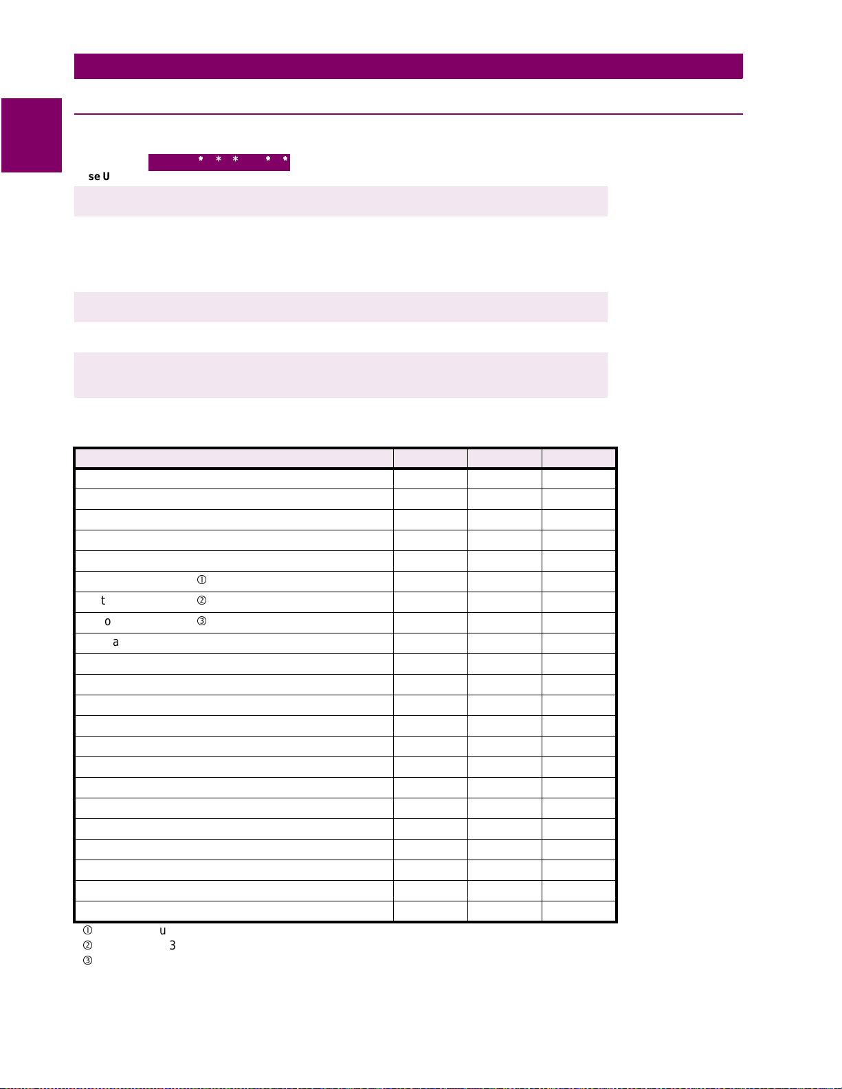
Table 1–1: ORDER CODES
Base Unit
Current Rating
Power Supply
Test Blocks
Protocol
Functions and
Features
Revision
DGP
DGP
* * *
||||||
1
5
0
1
2
3
4
Table 1–2: DGP SELECTION GUIDE
FUNCTIONS & FEATURES A B C
Stator Differential 87G
Current Unbalance 46
Loss of Exc itation 40-1, 40-2
Anti-motorin
Overcurrent Volta
Stator Ground 64G1
Stator Ground 64G2
Stator Ground 27TN
Neutral Overcurrent 51GN Overexcitation 24 (Volts/Hz)
Overvoltage 59
Undervoltage 27 Underfrequency 81-U 424
Overfrequency 81-O 422
Accidental Engergization Logic
Sequential Trip Logic
Voltage Transformer Fuse Failure VTFF
Oscillography Data Capture
RS232 Communications Ports 222
Printer Output
IRIG-B Input
DEC1000 compatible --
c
64G1 is Fundamental Frequency Overvoltage, also known as 59GN
d
64G2 uses 3rd harmonic comparator algorithm for enhanced security
e
27TN is 3rd Harmonic Undervoltage supervised by an adjustable window of forward power.
32
e Restraint 51V
c
d
e
| | | | |
| | | | |
||||
||||
||||
||||
||||
| | |
A
| | |
B
||
A
||
B
A
B
C
1.1.2 ORDER CODES & SELECTION GUIDE
Base Unit
1 Ampere Rated Current
5 Ampere Rated Current
One Power Supply, 48 V DC
One Power Supply, 110 to 125 V DC
One Power Supply, 220 to 250 V DC
Two Power Supplies, 4 8 V DC
Two Power Supplies, 110 to 125 V DC
With T est Blocks
Without Te st Blocks
GE Modem Protocol
Modbus RTU Protcol (DGP***BCA only)
Functions and Features – see DGP selection guide below.
|
|
|
DGP Revision A Firmware
A
✔✔✔
✔✔✔
✔✔✔
212
✔✔✔
✔✔✔
✔
-
✔✔✔
✔✔✔
✔✔✔
✔✔✔
✔✔✔
✔✔✔
✔
✔✔✔
-
✔
✔✔
✔✔
✔✔
-
✔
✔
1-
2
DGP Digital Generator Protection System GE Power Management

1 PRODUCT DESCRIPTION 1.1 GETTING STARTED
1.1.3 SPECIAL MODELS
In addition to the stan dard D GP model descri bed by the order codes a bove, s everal specia l mo dels ar e available. Some of these are shown below with a brief description.
DGP***AAA-0101 and DGP***AAA-0102
This model is similar to the standard DGP***AAA except for the following major changes:
• All digital inputs are rated for nominal voltage of 110 to 125 V DC instead of the standard 48 to 250 V DC
• The logic for function 51V is modified to remove fault detector supervision
• Seperate terminals are provided for the optional second power supply input
Refer to instruction book GEK-105552 for additional detail.
DGP***ABA-0005
This model is similar to the standard DGP***ABA except for the following major changes:
• Includes the Stator Ground 27TN function
• Includes oscillography data capture and IRIG-B input capabilities
• Suitable for application with 208 V AC nominal input
Refer to instruction book GEK-105587 for additional detail.
1.1.4 DEC 1000 CONTACT EXPANSION UNIT
1
The DEC 1000 is a relay expan sion unit for the DGP consisti ng of five form C relays and six form A relays.
These contacts can be used for signalling or alarm purposes. Any protection function available in the companion DGP relay can be sele cted for DEC output relay assignment. T he DEC 1000 is connected via the DGP
printer port PL2.
The DEC 1000 expansion unit is only compatible with the DGP
NOTE
kkkkk
C units.
GE Power Management DGP Digital Generator Protection System 1-
3

1.2 INTRODUCTION 1 PRODUCT DESCRIPTION
1.2 INTRODUCTION 1.2.1 GENERAL
1
The DGP Digital Generator Protection™ System is a microprocessor-based digital relay system that uses
waveform sampling of curren t and voltage inputs to provide protecti on, control and monitoring of gener ators.
These samples are used to compute current and vol tage phasors that are used for the protection-function
algorithms. The DGP™ system uses a man-machine interface (MMI) and GE-Link software for local and
remote communication respectively.
This instruction book describes all the functions available in the various standard DGP models. Refer
to the SELECTION GUIDE in the previous section to determine functions included in a specific model.
1.2.2 APPLICATION
The DGP system is designed to be used on hydroelectric, gas, and steam generating units. Any size of generator can be protected with this digital system.
More detailed appl ication cons ider ations are contai ned b elow i n the rem aining head ings of this sec tion and i n
Chapter 2: CALCULATION OF SETTINGS.
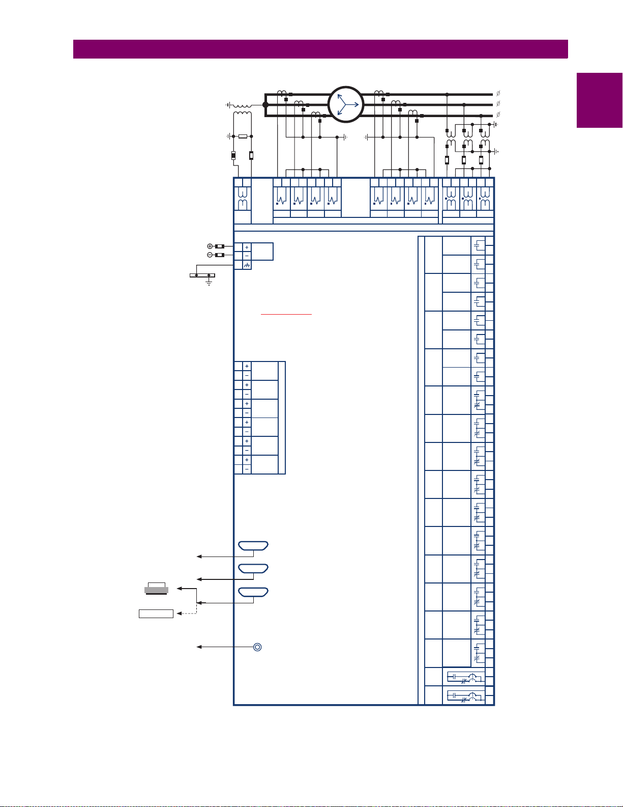
A typical wiring diagram for the DGP relay is shown on the following page.
1-
4
DGP Digital Generator Protection System GE Power Management
1 PRODUCT DESCRIPTION 1.2 INTRODUCTION
PRINTER
or
DEC1000
Contact Expansion
Unit
GROUND
BUS
RS-232
RS-232
PRINTER
IRIG-B
CONTROL
POWER
g
AH
AH
AH
AH
1
2
3
4
IBR IBS
IAR
GE Power Management
AG1
AG2
AH
12
VOLT
BH
14
GND
AH
11
DGP
Digital Generator Protection
BG
8
GENERATOR
BG
OFF LINE
7
BG
TURBINE
6
INLET VALVE
BG
LIMIT SWITCH
5
BG
EXTERNAL
4
TRIP 1
BG
3
BG
2
BG
1
BE
4
BE
3
BE
2
BE
1
OSCILLOGRAPH
Disable Prot.
DB9
DB25
DB25
EXTERNAL
TRIP 2
TRIGGER
EXT. VTFF/
(REAR)
(FRONT)
(REAR)
(REAR)
PL3
TS
PU
IN
PL1
PL2
A
C(B)
B(C)
BH
BH
BH
AH
AH
AH
AH
5
6
7
8
ICR ICS
INR INS
CURRENT
INPUTS
BH
1
2
3
4
IAS
A
B
C
BH
BH
BH
BH
BH
BH
BH
8
5
6
7
94G
94G1
94G2
94G3
74A
74B
74C
S
T
U
P
T
U
O
74D
74FF
DOR 12
DOR 13
DOR 9
74 NC
74 CR
POWER
SUPPLY
ALARM 1
POWER
SUPPLY
ALARM 2
9
10
VA
VOLTAGE
TRIP A
(DRY)
TRIP A
TRIP B
(DRY)
TRIP B
TRIP C
(DRY)
TRIP C
TRIP D
(DRY)
TRIP D
ALARM A
ALARM B
ALARM C
ALARM D
VT FUSE FAIL
TEST PICKUP
TEST TRIP
SPARE
SELF TEST
NON
CRITICAL
SELF-TEST
CRITICAL
BH
AH
11
12
9
VB
704753A7.CDR
AH
10
VC
BE
10
BF
10
BE
(+)
14
BF
(-)
14
BE
9
BF
9
BE
(+)
13
BF
(-)
13
BE
8
BF
8
BE
(+)
12
BF
(-)
12
BE
7
BF
7
BE
(+)
11
BF
(-)
11
AG
14
AF
14
AE
14
AG
13
AF
13
AE
13
AG
12
AF
12
AE
12
AG
11
AF
11
AE
11
AG
10
AF
10
AE
10
AG
6
AF
6
AE
6
AG
5
AF
5
AE
5
AG
9
AF
9
AE
9
AG
8
AF
8
AE
8
AG
7
AF
7
AE
7
BF
5
BE
5
BF
BF
6
6
BE
BF
6
6
1
Figure 1–1: TYPICAL WIRING DIAGRAM
GE Power Management DGP Digital Generator Protection System 1-
5
1.3 PROTECTION FEATURES 1 PRODUCT DESCRIPTION
1.3 PROTECTION FEATURES 1.3.1 DESCRIPTION
1
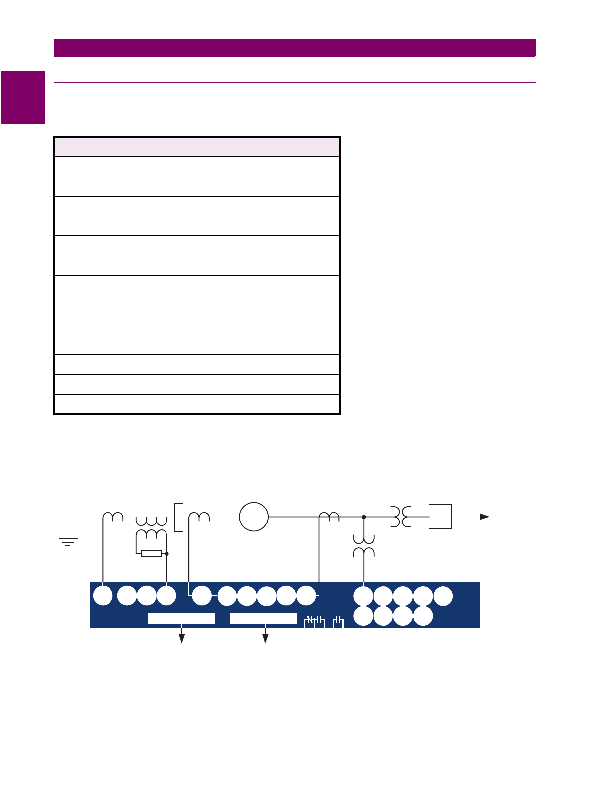
The following protection functions are included with the DGP system.
Table 1–3: DGP PROTECTION FUNCTIONS
PROTECTION FUNCTION ANSI CODE(S)
Stator Differential 87G
Current Unbalance 46
Loss of Excitation 40
Anti-Motoring 32
Time Overcurrent with Voltage Restraint 51V
Stator Ground 64G1, 64G2, 27TN
Ground Overcurrent 51GN
Over-excitation 24
Overvoltage 59
Undervoltage 27
Over and Underfrequency 81
Voltage Transformer Fuse Failure VTFF
Accidental Energization AE
A single-line diagram for the DGP is shown below.
GEN.
51GN
27NT
64G2
64G1
RS232
87G
VTFF
51V
32
RS232
40
46
24
VTFF
64G2
51V
GSU
Transf.
32
40
27
59
52G
81
TO
POWER
SYSTEM
DGP
1-
To
MODEM
To
ALARM
LAPTOP
PC
TRIP
Figure 1–2: SINGLE LINE DIAGRAM
6
DGP Digital Generator Protection System GE Power Management

1 PRODUCT DESCRIPTION 1.3 PROTECTION FEATURES
1.3.2 STATOR DIFFERENTIAL (87G)
This function provides high -speed pr otection of the genera tor stat or during inter nal pha se-to- phase an d threephase faults. It uses a product-restraint algorithm with dual-slope characteristic described in Section 2.3.2:
STATOR DIFFER ENTIAL 87G on page 2–13. R efer to Figure 1–3: S IMPLE LOGIC DIAG RAM – 87G, 32 , 27 ,
59, AND AE on page 1–12 for the logic diagram of this function.
Function 87G will not operate for turn-to-turn faults in the machine windings.
It will also not operate for single-phase-to-ground faults if the system is ungrounded or high-impedance
grounded. Phase-to-ground protection by this function requires that the neutral of the machine (or another
machine operating i n parallel) be grounded. A small portio n of the windi ng next to th e neutral will no t be protected, the amount being determined by the voltage necessary to cause minimum pickup current to flow
through the neutral-to-g round impedance. Current-limiting devices in the neutral-ground c ircuit increase this
impedance and will decrease the ground-fault-protection coverage of this function.
1.3.3 CURRENT UNBALANCE (46T)
There are several cause s of generator unba lance . Som e of th ese i nclude unbala nced loads , unbal ance d sy s-
I
tem faults, and/or op en circuits. Th e negative-seque nce component (
) of stator current is directly r elated to
2
this unbalance and sets up a co unter-rota tin g flux fie ld in the mach ine . This in turn ca uses local he ating in the
rotor iron. The c apability of machines to withstand heating caused by unbalance current s is typically experessed in terms of an constant, and is supplied by the manufacturer of the machine.
The current unbalance tri p function (46T) of the DGP provides operating-tim e characteristics expressed as
2
I
T
= K, as shown in Fig ure 2 –6: TIME CURRENT CHARACTE RIS TIC O F 4 6T FUNC TI ON on pa ge 2–1 9. A
2
2
I
T
2
linear reset characteristic is incorporated to approximate the machine cooling following an intermittent currentunbalance condition. In addition to 46T, the DGP s ystem also includes a current-unba lance alarm function,
46A, which is operated by the nega tive-sequence component (I2) with an adj ustable pickup and time delay.
See Figure 1–4: SIMPLE LOGIC DIAGRAM – 46, 40, AND 51V on page 1–13 for the logic diagram.
1
1.3.4 LOSS OF EXCITATION (40)
This function is used to detect loss of excitation on synchronous machines. It includes two mho characteristics
looking into the machine, each with adjustable reach, offset, and time delay. Logic is provided to block this
function by presence of a negative-sequence voltage (indic ating a voltage trans former fuse failure VTFF condi tion) and/or an external VTFF Digital Input DI6 (see Figure 1–4: SIMPLE LOGIC DIAGRAM – 46, 40, AND 51V
on page 1–13).
Excitation can be los t due to ina dverten t trippi ng of the fi eld brea ker, open or short circui t on the fie ld wind ing,
regulator failure, or loss of the sour ce to the fie ld win ding. Loss of exci tation can b e dama ging to the m achin e
and/or detrimental to t he operation o f the sys tem. When a sy nchronous generator l oses exci tation, it will tend
to act as an induction generator: it will run above normal speed, operate at reduced power and receive its excitation (VARS) from the system. The impedance seen by a relay looking in to a generator will depend on the
machine characteristics, the load flow prior to the loss of excitation, and the type of excitation failure.
Studies indicates that first zone mho function (40-1) can be set to detect severe cases of excitation failure with
a shorter time d elay, whereas the second zone (40-2) c an be set to det ect all the excitation failure cases. A
longer time delay s etting is required for t he 4 0- 2 fu nc tio n fo r se cu ri ty duri ng sta ble power system swin g c ond itions. Figure 2–7: MHO CHARACTERISTICS FOR 40-1 & 40-2 FUNCTIONS on page 2–21 shows the characteristics of this function.
GE Power Management DGP Digital Generator Protection System 1-
7

1.3 PROTECTION FEATURES 1 PRODUCT DESCRIPTION
1.3.5 ANTI-MOTORING (32)
1
On a total or partial loss of prime mover, if the power generated is less than no-load losses of the machine, real
power will start flowing into the generator. Typical motoring power of different kinds of prime movers are shown
in the table below. For a specific application, the minimum motoring power of the generator should be obtained
from the supplier of the unit.
The DGP system includes a reverse power function with adjustable time-delay. Either one or two (32-1 & 32-2)
independent setpoints are incorporated depending on the model number.
Table 1–4: TYPICAL MOTORING POWER
TYPE OF PRIME
MOVERS
Gas Turbine 10 to 100
Diesel 15 to 25
Hydraulic Turbine 2 to 100
Steam Turbine 0.5 to 4
The 32-1 can be configured as a part of sequential tripping logic as shown in Figure 1–3: SIMPLE LOGIC DIAGRAM – 87G, 32, 27, 59, AND AE on page 1–12. If the sequential trip logic is used, 32-1 is enabled when closing of turbine inlet v alves is indicated by digital in put DI2 following a turbine trip . The trip sequence is then
continued when timer TL1 times out. The 32-2, if included, is not dependent on the DI2 and is primarily
intended to provide bac k up t o th e s equ ent ial trip . If the sequential trip is no t en abl ed, the 32-1 can be used as
anti-motoring similar to 32-2.
A system must be protected against prolonged generator contribution to a fault. The DGP incorporates a timeovercurrent functio n with vo ltage re straint (51V ) to provi de part of the syst em backu p protecti on. As s hown in
Figure 1–4: SIMPLE LOGIC DIAGRAM – 46, 40, AND 51V on page 1–13, this function is supervised by a fault
detector and VTFF. The VTFF supervision can be by an internal an d/or external (DI6) VTFF fun ction. See Section 2.3.7: OVERCURRENT WITH VOLTAGE RESTRAINT (51V) on page 2–22 for the characteristic curves of
the 51V . Note that a separate algorithm is processed for each phase, with the restraint provided by corresponding phase voltage. The restraint is proportional to the magnitude of the voltage and is independent of the phase
angle. A linear reset characteristic is incorporated for this function.
MOTORING POWER IN %
OF UNIT RATING
1.3.6 TIME OVERCURRENT WITH VOLTAGE RESTRAINT 51V
1.3.7 ST ATOR GROUND (64G/27TN)
This function consists of two overlapping zones (64G1 and 64G2/27TN) to detect stator ground faults in a highimpedance-grounded generator system. The 64G1 is standard in all DGP models; however, the 64G2/27TN
function is provided in some models only. Together, the two zones cover 100% of the stator windings. See Figure 1–5: SIMPLE LOGIC DIAGRAM – 64G1, 64G2, 51GN, AND 24 on page 1–14.
Normally the generator-stato r neutral has a potential cl ose to ground. With the occurren ce of a stator ground
fault, a potential increase will occur on the neutral for all faults except those near the neutral. 64G1 uses a fundamental-frequency neutral overvoltage to cover about 95% of th e stator winding, depending on the pic kup
voltage setting. Alternately, 64G1 can be used as a generator-bus ground detector in a high-impedance
grounded or an ungrounded system. For this application, the VN input must be a zero-sequence voltage
derived from the generator bus, and functions 64G2/27TN must be disabled.
1-
8
DGP Digital Generator Protection System GE Power Management

1 PRODUCT DESCRIPTION 1.3 PROTECTION FEATURES
64G2 is based on the perc entage of third-harmonic vo ltage at the generator neutral (VN 3) compared to the
total third-harmonic vol tage gener ated. This func tion is design ed to cover 15 % of the neutral end o f the stator
windings, and is supervised by fundamental and third-harmonic voltage thresholds. These thresholds are fixed
at 30 and 0.5 volts respectively. The third-harmonic comparator method eliminates the need to know the generator harmonic characteristic to use or set this function.
proper operation of 64G2
27TN is the third- harmonic neutral u ndervoltage functio n with a forward power supervision and can be used
with either wye or delta connected VTs. The percentage of stator windings covered by this function depends on
its threshold setting as well as the VN3 generated b y the machine at the time of th e fault. The magnitude of
VN3 under normal condi tions is a function of several factors, su ch as type of generator, load current, load
power factor, system status, etc. It can be very small (nearly zero) under some conditions. T o enhance security
during low VN3 vo lta ge conditions, this f unc tio n can b e i nhi bi ted by a se tt able window of forward power. However, it should be noted that other condi tions influenci ng the VN3 vol tage may make 2 7TN insecu re. In these
cases, function 64G 2 (available in some models; see the DGP nomenclature guide) or some other means
should be considered.
Digital input DI1 can be co nfigured to bloc k 64G2/27T N when the gener ator is off-line. Thi s provision is made
to enhance security of the functions under conditions such as static start of a gas turbine generator. Temporary
ungrounding of generator neutral during the static start can look like a ground fault near the neutral.
.
Note that wye-connected VTs are required for
1.3.8 GROUND OVERCURRENT (51GN)
1
51GN is an inverse overcurrent function available in some models. It can be used to detect stator ground faults
in a high or low resist ance grounded generator sy stem. See Fig ure 1–5: SIM PLE LOGIC DIA GRAM – 64G1,
64G2, 51GN, AND 24 on pa ge 1–14 for simplified logic diagram and Figure 2 –16: 51GN TIME-CURRENT
CHARACTERISTICS on page 2–39 for the inverse time-current characteristics.
This function uses current INR which can be derived by residual connection or by using a generator neutral CT
as noted in F igures 1–9: ELEMENTARY DIAGRAM WITH TE ST BLOCKS, WYE VTs and 1–12: ELEMENTARY DIAGRAM WITHOUT TEST BLOCKS, DELTA VTs.
Since this function is independen t of the phase current inputs , it can alterna tely be connect ed to a CT in the
neutral of the generator step-up transformer.
1.3.9 OVEREXCITATION (24)
Overexcitation can b e caus ed by reg ulator failure , load r eject ion, or an exce ssiv e excit ation wh en the ge nerator is off-line. It can also resul t from decr easing spee d while the regulator o r an operator a ttempts to m aintain
rated stator voltage. The Volts/Hertz quantity is proportional to magnetic flux in the generator and step-up
transformer cores, and is use d to detect the overexcitation condition. Se e Figure 1–5: SIMPLE LOGIC DIAGRAM – 64G1, 64G2, 51GN, AND 24 for details.
The overexcitation protection includes trip (24T) and alarm (24A) functions. 24T consists of an inverse function
and an instantaneous fu nction with time-delay characteris tics. The combination of these two char acteristics
allows the 24T setting to cl osely follow the generator and/or ste p-up transformer V/Hz limit curve. Bo th 24A
and 24T are computed for each of the three phase voltages (see Table 2–3: 24A VOLTAGES on page 2–30).
Function 24T can be c onfigu red to operate d ifferent ou tput re lays for gene rator on -lin e and o ff-line condi tions.
This function incorpora tes a user-settable li near reset character istic to mimic machi ne cooling. The figu res in
Section 2.3.12: OVEREXCITATION TRIP (VOLTS/HERTZ: 24T) show the characteristics of this function.
GE Power Management DGP Digital Generator Protection System 1-
9

1.3 PROTECTION FEATURES 1 PRODUCT DESCRIPTION
1.3.10 OVERVOLTAGE (59)
1
This function consists of a positive-sequence overvoltage with an user selectable inverse or definite time characteristic. See Figure 1–3: S IMPLE LOGIC DIAGRAM – 87G, 32, 27, 59, AND AE on page 1–12 fo r the logic
diagram and Figure 2–15: 59 TIME-VOLTAGE CHARACTERISTICS on page 2–35 for the inverse time-voltage
characteristics. A l inear reset charact eristic is incorp orated for this function. The overvoltage functi on can be
considered as a backup to the Volts/Hz function. Some possible causes of this cond ition are a system dis turbance or regulator failure.
1.3.11 UNDERVOLTAGE (27)
This function consists of a positive-sequence undervoltage with an user selectable inverse or definite time
characteristic. See Figur e 1–3: SIMPLE LOGIC DIAG RAM – 87G, 32, 27, 59, AND AE on p age 1–12 for the
logic diagram and Figu re 2–17: 27 TIME -VOLTAGE CHARACTER ISTICS on pa ge 2–40 for the inv erse timevoltage characteristics. A linear reset characteristic is incorporated for this function.
1.3.12 OVER AND UNDERFREQUENCY (81)
This function provides over and underfrequency protection, each with an adj ustable time delay. Two or four
over and underfrequency ste ps are provided dep ending on the model. Al l frequency functi ons are supervise d
by an adjustable positive-sequence voltage level. This undervoltage cut-off level and/or digital input DI1 can be
used to block the freq uency functions during sta rt-up. Fr equency dis turbance c an occur due to a system fault
or islanding of the unit or an unconnected unit can operate at abnormal frequency due to malfunction of speed
control. Figure 1 –6: SIMPLE LOGIC DIA GRAM – 81-O A ND 81-U on page 1 –15 show s the l ogic diag ram for
this function.
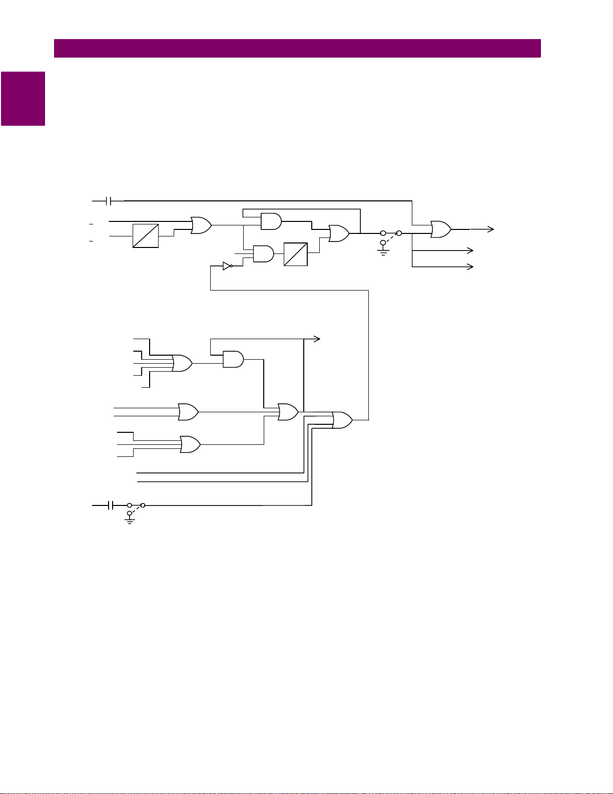
1.3.13 VOLTAGE TRANSFORMER FUSE FAILURE (VTFF)
Functions 40 and 51V may operate for a full or partial loss of AC potential caused by one or more blown fuses.
The DGP makes provisions to block tripping by these functions when a fuse failure is detected; all other protection functions are a llowe d to t rip. Fig ure 1–7: SIMP LE L OGIC DIA GRAM – VT F USE FAILURE on pag e 1–1 6
shows the logic diagram for the VTFF function.
If AC potential is lost on one or more phas es, the negative-seque nce voltage (V2) rise s and/or the positivesequence voltage ( V1) drops. Either V2 > 15V or V1 < 50V provides a basic ind ication o f the VTFF c ondition .
This signal is supervi sed by a Distur bance Dete ctor (DD) and gene rator posit ive-se quence cu rrent (I1) dete ctor (see three-inp ut AND gate on the log ic diagram). Supervision by the DD and I1 signa ls provide security
against false ope ration du ring fault a nd genera tor out of service conditio ns respec tively. Security is enhance d
by use of the A/0 and B/0 timers shown in the logic diagram.
Signal DD is derived from a combination of sequence current levels, change in levels, and pickup flags of various protection functions as shown in the logic diagram.
The VTFF logic allows integration of an external VTFF contact. Either of the two fuse-failure signals or both
signals can be configured to block tripping of functions 40 and 51V.
Detection of VTFF energizes the 74FF (Fuse Failure alarm) relay, de-energizes the 74CR (critical alarm) relay,
and turns the status LED red, even though all protection functions except 40 and 51V are unaffected.
1-
10
DGP Digital Generator Protection System GE Power Management

1 PRODUCT DESCRIPTION 1.3 PROTECTION FEATURES
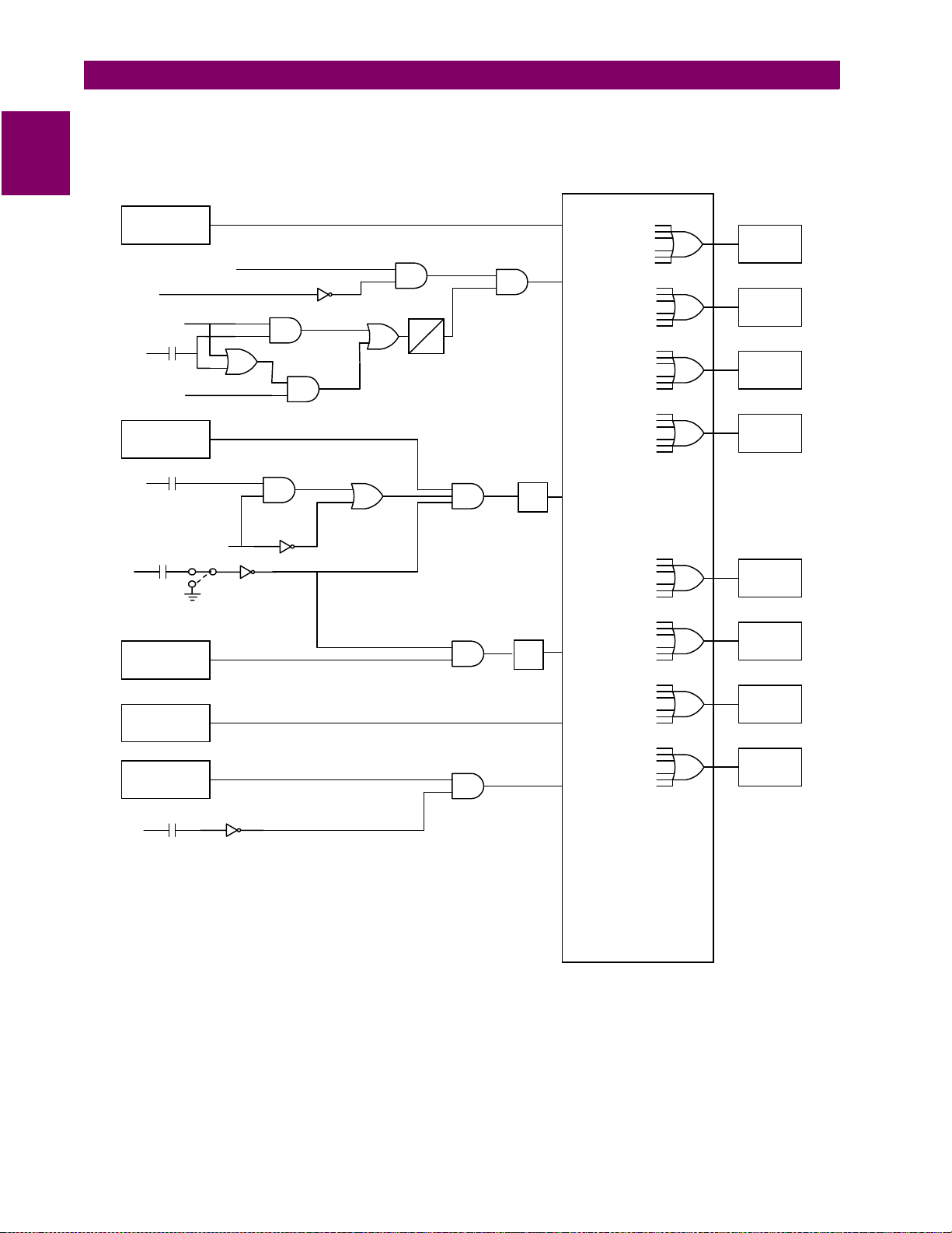
1.3.14 ACCIDENTAL ENERGIZATION (AE)
The DGP includes logic to detect accidental energization of the gener ator (see Figure 1–3: SIMPLE LOGIC
DIAGRAM – 87G, 3 2, 27, 59, AND AE on page 1–12). When a generator is energized while at standstill or
reduced speed, it behaves and acc elerates as an induction mot or. The machine terminal voltage and current
during such an event will be a function of generator, transformer, and system impedances.
An instantaneous over cu rren t si gna l (50) is used to det ect t he acci de ntal ener g izati on. T his s ig nal is arm ed by
a logic signal de rived from positive- sequence voltage and GEN O FF LINE input DI1. These two "arming " signals can be confi gured in AND or O R mode by Se tting 2703:
after the generator is taken out of service. The logic automatically disarms itself during a normal start-up
sequence when the voltage detector picks up and/or the generator is on-line.
For the AE logic to perform, special precautions must be taken to ensure that the DGP system and associated
trip circuits remain in service when the generator is out of service. Additionally, the generator off-line input, DI1,
must be reliable. It should also be noted that the pickup flag of function 51V is used as signal 50; therefore this
logic will automatically be disabled if function 51V is disabled.
AE ARM
. The 50 function is armed 5 seconds
1
GE Power Management DGP Digital Generator Protection System 1-
11
1
1.3 PROTECTION FEATURES 1 PRODUCT DESCRIPTION
Stator
Differential
50 (51V Pickup Flag)
VTFF
V1 < 30V
DI1
(+)
Gen. Off-line
OR
AE ARM
Reverse Pwr.
No. 1
(+)
DI2
Turbine Inlet Valve
Closed
Seq. Trip Enabled
DI1
(+)
Gen.
Off-Line
SELBKDI1
Reverse Pwr.
No. 2 (1)
AND
AND
AND
AND
PU
OR
PU=5 sec
DO=0.25 sec
DO
ANDOR
AND
AND
AND
TL1
TL2
87G
87G
AE
AE
32-1
32-2
OR
OR
OR
OR
OR
OR
TRIP A
94G
TRIP B
94G1
TRIP C
94G2
TRIP D
94G3
ALARM
74A
ALARM
74B
Overvoltage
59
Undervoltage
(+)
(1)
DI1
Gen.
Off-Line
AND
27
NOTES:
(1) Indicates an optional function (includes associated logic). Refer to
CONFIGURABLE
DGP nomenclature selection guide for available functions in a
specific model.
(2) Each of the available protection functions can be configured to
operate any combination of the 8 output relays (4-Trip and 4-Alarm).
Figure 1–3: SIMPLE LOGIC DIAGRAM – 87G, 32, 27, 59, AND AE
LOGIC (2)
OR
OR
ALARM
74C
ALARM
74D
1-
12
DGP Digital Generator Protection System GE Power Management
1 PRODUCT DESCRIPTION 1.3 PROTECTION FEATURES
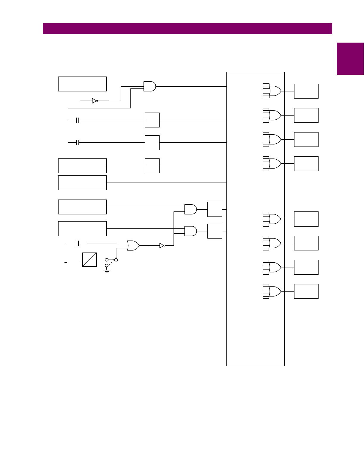
1
Overcurrent
(voltage restraint)
VTFF + DI6
FD
(+)
(+)
DI3
External Trip - 1
DI4
External Trip - 2
Current Unbalance
(Alarm)
Current Unbalance
(Trip)
Loss of Excitation
Zone 1
Loss of Excitation
Zone 2
DI6
(+)
V
2
Ext. VTFF
>
PU
15V
PU=3 Samples
DO=5 Samples
DO
ENA
SELV2SUP
DIS
OR
AND
TL21
(1)
TL22
(1)
TL14
87G
51V
OR
TRIP A
94G
AE
TRIP B
94G1
TRIP C
94G2
TRIP D
94G3
DI3
DI4
46A
OR
OR
OR
46T
TL12AND
TL13AND
40-1
40-2
OR
OR
OR
ALARM
74A
ALARM
74B
ALARM
74C
OR
ALARM
74D
NOTE:
(1) Timers TL21 and TL22 are available in models DGP***ACA only.
(2) Each of the available protection functions can be configured to
operate any combination of the 8 output relays (4-Trip and 4-Alarm).
CONFIGURABLE
LOGIC (2)
DSPLGC2.VSD
Figure 1–4: SIMPLE LOGIC DIAGRAM – 46, 40, AND 51V
GE Power Management DGP Digital Generator Protection System 1-
13
1
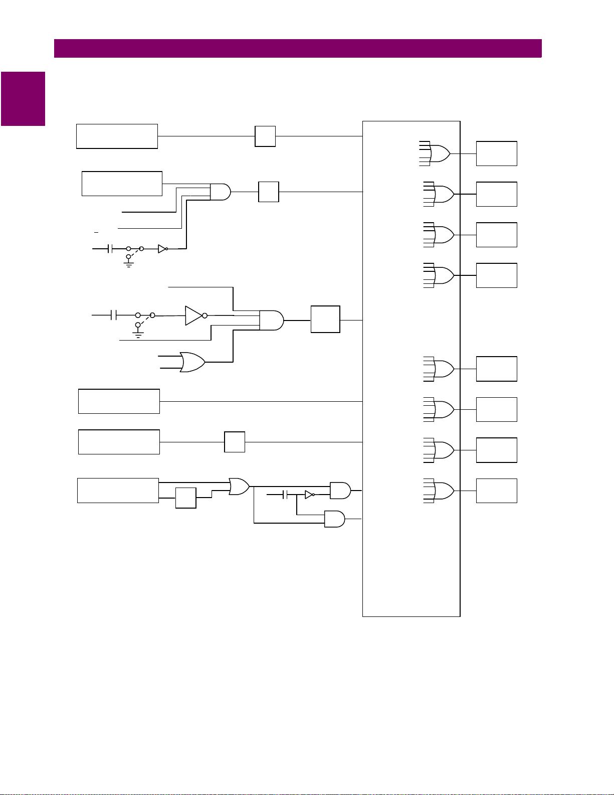
1.3 PROTECTION FEATURES 1 PRODUCT DESCRIPTION
Stator Ground
Zone 1
Stator Ground
Zone 2 (1)
VP3 > 0.5V
V1
30V
>
DI1
(+)
Gen.
Off-Line
V
≤
N3
GEN. OFF-LINE
(+)
DI1
V
25V
≥
1
SELBKDI1
27TN PICKUP
SELBKDI1
POWER < FORPWR-L
POWER > FORPWR-H
Neutral Overcurrent
(1)
OR
AND
TL4
TL5
AND
TL20
64G1
64G2
27TN
(1)
51GN
OR
OR
OR
OR
OR
OR
TRIP A
94G
TRIP B
94G1
TRIP C
94G2
TRIP D
94G3
ALARM
74A
ALARM
74B
Overexcitation
(Alarm)
Overexcitation
(Trip)
Time
Inst
TL7
TL6
OR
(+)
DI1
Gen.
Off-Line
AND
AND
24A
24T
(On-Line)
24T
(Off-Line)
NOTES:
(1) Indicates an optinal function (includes associated logic). Refer to
DGP nomenclature selection guide for available functions in a
specific model.
CONFIGURABLE
(2) Each of the available protection functions can be configured to
operate any combination of the 8 output relays (4-Trip and 4-Alarm).
Figure 1–5: SIMPLE LOGIC DIAGRAM – 64G1, 64G2, 51GN, AND 24
LOGIC (2)
OR
OR
ALARM
74C
ALARM
74D
1-
14
DGP Digital Generator Protection System GE Power Management

1 PRODUCT DESCRIPTION 1.3 PROTECTION FEATURES
1
Under Frequency
Set Point - 1
Under Frequency
Set Point - 2
Under Frequency
Set Point - 3 (1)
Under Frequency
Set Point - 4 (1)
DI1
(+)
Gen.
Off-Line
SELBKDI1
V1 > UVCUTOFF
Over Frequency
Set Point - 1
AND
AND
AND
AND
AND
TL8
TL9
TL10
TL11
TL15
81-1U
AE
81-2U
81-3U
81-4U
81-1O
OR
OR
OR
OR
OR
OR
TRIP A
94G
TRIP B
94G1
TRIP C
94G2
TRIP D
94G3
ALARM
74A
ALARM
74B
Over Frequency
Set Point - 2
AND
TL16
81-2O
Over Frequency
Set Point - 3 (1)
AND
TL17
81-3O
Over Frequency
Set Point - 4 (1)
AND
TL18
81-4O
NOTES:
(1) Indicates an optional function (includes associated logic). Refer to
DGP nomenclature selection guide for available functions in a
specific model.
(2) Each of the available protection functions can be configured to
operate any combination of the 8 output relays (4-Trip and 4-Alarm).
CONFIGURABLE
Figure 1–6: SIMPLE LOGIC DIAGRAM – 81-O AND 81-U
OR
OR
LOGIC (2)
ALARM
74C
ALARM
74D
GE Power Management DGP Digital Generator Protection System 1-
15
1
1.3 PROTECTION FEATURES 1 PRODUCT DESCRIPTION
DI6
(+)
External VTFF
V2
15V
>
50V
V1
<
51V Pickup Flag
40 Pickup Flag
87G Pickup Flag
51GN Pickup Flag
21 Pickup Flag (Fut.)
I0 ≥ 0.6 / *
∆
∆
I2 ≥ 0.6 / *
∆
I0| ≥ 0.2 / *
|
I1| ≥ 0.2 / *
|
∆
|∆I2| ≥ 0.2 / *
64G1 Pickup Flag
64G2 Pickup Flag
DI1
(+)
Gen.
Off-Line
PU
PU=9000 samples
DO=0
SELBKDI1
DO
OR
I1 > 0.1/*
OR
OR OR
OR
AND
AND
AND
PU
DO
PU = 36 samples
DO = 0
FD
OR
Supervise
51V,
21(Future)
OR
DD
ENA
DIS
VTFF
VTFF + DI6
OR
Supervise
51V,
21(Future)
VTFF Alarm
Critical Alarm
1-
NOTE:
* = 1 FOR 5 AMP RATED DGPs.
* = 5 FOR 1 AMP RATED DGPs.
Figure 1–7: SIMPLE LOGIC DIAGRAM – VT FUSE FAILURE
16
DGP_VTFF.VSD
DGP Digital Generator Protection System GE Power Management

1 PRODUCT DESCRIPTION 1.4 OTHER FEATURES
1.4 OTHER FEATURES 1.4.1 INPUTS
The DGP system takes eight current and four voltage inputs (refer to Section 1.5: ELEMENTARY DIAGRAMS).
The input currents in terminals BH1, BH3, and BH5 (I
, IBS, and ICS) are used to process functions 46, 40, 32,
AS
and 51V. As noted in the elementary diagrams, these currents can be derived from system side or neutral side
CTs as de sired. Either the sy stem or n eutral s ide CTs can be used fo r these functi ons if the Stator D ifferential
(87G) function is enabled.
The current input s I
and INR are derived from th e resid ual connec tions of t he respe ctive phas e CTs and do
NS
not require dedicated neutral CTs. Zero-sequence current at system and/or neutral side of the generator stator
windings is calculated and then compared with the measured I
and/or INR values by the DGP as a part of the
NS
background self-test.
The I
icated neutral CT can be used for the input I
The DGP phase volta ge i npu ts c an be wye or delta and are derived f ro m the gen er ato r term in al v ol tag e. V
current is used to process the 51GN function (not available on DGP***AAA models). If desired, a ded-
NR
NR
.
is
N
derived from the generator neutral grounding transformer.
A time synchronizin g signal can be connected to the DGP for syn chronization to within 1 ms of a referenc e
clock. Either IRIG-B or GE's G-NET system signal can be used. This signal is required only if it is necessary to
synchronize the DGP to an external reference clock.
Six digital inputs can be connected to the DGP. Two of these inputs (DI3 and DI4) are a ssigned for possi ble
routing of external trip/alarm signals to take advantage of the output configuration or sequence-of-events capability. Generator off-line (DI1), turbine inlet-valve-close indication (DI2), and external VTFF (DI6) inputs are
used for various relay logic functions. A contact input, (DI5), can also be used to trigger the optional oscillography feature. In some models, the DI6 input can be configured as external VTFF or DISABLE ALL PROTECTION (refer to Section 1.5: ELEMENTARY DIAGRAMS for details).
1
The digital input circuits are universally rated for nominal control voltages of 48 to 250 V DC.
1.4.2 OUTPUT RELAYS
The DGP system includes ei ght user-configur able output relays. Four of these relays (94G, 94G1, 94G2 and
94G3) are high speed (4 ms) trip-duty rated with two form A contacts each. The remaining four (74A, 74B, 74C
and 74D) are standard speed (8 ms) with one form C contact each, intended for alarms. Each of the protection
functions can be configured to operate any number of these output relays. The trip outputs are intended for, but
not limited to, the following purposes:
• 94G: trip a lockout relay to shut down the machine
• 94G1: trip field breaker
• 94G2: trip main generator breaker or breakers
• 94G3: operate a lockout relay to trip turbine.
In addition to the configu rable output relays, fi ve pre-defined alarm duty relays with one form C c ontact each
are included. These alar m relays inc lude critical and non-cri tical self- test alarms ( 74CR and 74NC) , the VTFF
alarm (74FF), and loss of power-supply alarms (PS1 and PS2). The form C contact of each of the alarm relays,
except PS1 and PS2, are wired out to the terminal block. A hard wire jumper is used to select either the form A
or the form B conta ct of each of the PS1 and P S2 relays, as shown in Figure 3–3: DGP POWER S UPPLY
MODULE on page 3–4.
All alarm relays, wi th the exc eption of 74CR, PS1 a nd PS2, are e nergized wh en the appr opriate al arm conditions exist. Relays 74CR, PS1 and PS2, however, are energized under no rmal conditions and will dro p out
when the alarm conditions exist.
GE Power Management DGP Digital Generator Protection System 1-
17

1.4 OTHER FEATURES 1 PRODUCT DESCRIPTION
Also included are two additional relays (TEST PICKUP and TEST TRIP) that can be configured to operate by a
selected protectio n function pi ckup flag an d trip output. T hese two outpu ts are inten ded to facilitate testing of
1
the selected protection function.
A Contact Expansi on Unit is al so av ailable whic h can be u sed with DGP* **ACA models . The Gene ral El ectric
DEC1000 Contact Expa nsion Unit provides eleven a dditional output relays that can be factory config ured to
user specifications. Refer to the GE Power Mana gement Product Ca talog, the GE Pow er Management Products CD, or instruction book GEK-105561 for additional details on the DEC1000.
1.4.3 START-UP SELF-TESTS
The most comprehens ive testing of the DGP is perform ed during powe r-up. Since the DG P is not perform ing
any protection activities at that time, tests (such as RA M tests) that would norm ally be disruptive to ru n-time
processing are per formed during the start-up. Al l processors p articipate in th e start-up sel f-test process. T he
processors commun ic ate th eir results to each other so that any failures foun d c an be r epo rt ed to t he us er an d
to ensure each processor successfully completes its assigned self-tests before the DGP system begins protection activity.
During power-up, the micr oprocessors perfor m start-up self-test s on their associated ha rdware (PROM, local
RAM, shared RAM, interrup t controller, timer chip, serial and parallel I/O ports, non-volatile memory, analog
and digital I/O circuitry, MMI hardware, etc.). In addition, the DGP system verifies that the PROM version numbers in all processor boards are compatible. The components tested at start-up are listed in Table 6–1: ST ARTUP SELF-TESTS on page 6–2.
In most cases, if any critical self-test failure is detected, the DGP will not continue its start-up but will not cause
a reset. An attempt will be made to store the sy stem status, to initi alize the MMI and remote communications
hardware/software for communication status, and to print a diagnostic message. The critical alarm relay will be
de-energized.
If no failures are detected, the DGP completes initialization of its hardware and software. Next, each processor
board (DAP and S SP) will enable the outputs. As a f inal step, the DG P checks the res ults of all the te sts to
determine whether to turn the front panel status LED to green.
The start-up procedure takes approximately one minute. As soon as the SSP successfully completes its
PROM test and in itializ es the disp lay h ardwa re, th e mes sage
system initialization is completed, the display is blanked and the relay begins acquiring and processing data.
Each of the processors has "idle time" when the system is in a quies cent state; that is, when the DGP is not
performing fault or po st-fa ult proc essi ng. During this i dle tim e, each proce ssor pe rforms backg round self-tes ts
that are non-disruptive to the foreground proc essing. If any back ground self-tes t fails, the test is repeat ed. To
declare a component FAILED , the test must fail three consec utive times. In the case of criti cal failures, the
DGP forces a self reset to resume operation again after an intermittent failure. The reset activities are identical
to the start-up activities except that not all start-up self-tests are performed.
A reset is not reported to the user by the DGP system. If the reset is successful, no message is printed, no failure status is recorded, an d the critical alarm is not generated. However, during the reset proc edure, the red
LED on the MMI panel will light and a failure code ma y appear on the MM I displa y. If the reset is not successful, the processor boar d will be shut down, leaving the MMI panel displaying the error information. Ref er to
Section 6.4: ERROR CO DES on page 6–7 fo r error codes. To prevent continual resets in the ca se of a solid
failure, both hardware and software will permit only four resets in a one hour period. On the fifth reset, the DGP
will not perform initialization, but will attempt to initialize MMI, communications, and the critical alarm output, as
in the case of a start-up with a critical self-test failure.
INITIALIZING
will be displayed. When the DGP
1.4.4 RUN-TIME SELF-TESTS
1-
18
DGP Digital Generator Protection System GE Power Management
 Loading...